

Bosch DS940P, DS940PT Installation Instructions Manual
DS940P/DS940PT
Passive Infrared Detector
With Pet Immunity
Installation Instructions
1.0 Description
The DS940P is a high performance Passive Infrared (PIR) Motion Sensor which uses advanced signal processing to provide outstanding
catch performance and unsurpassed false alarm immunity. It is designed to detect movement in the interior of a structure by sensing the
Infrared energy emitted from the human body as it moves across the sensor’s field of view. When motion is detected the unit sends an alarm
signal to the Control Panel. With Bosch Security Systems Pet Friendly® pet immunity, the DS940P will not detect a dog up to 30 pounds (13
kilos), two cats, or numerous rodents. This pet immunity feature has not been tested by Underwriters Laboratories.
2.0 Specifications
• Input Power: 9-15 volts DC
• Current Draw: 17 mA @ 12 VDC (standby and maximum)
• Standby Power: No internal standby battery. For UL Listed Prod-
uct Installations, 4 hours (68 mAh) standby power must be provided.
• Relay Form “A” Normally Closed (NC) contact set rated
for 125 mA@ 28 volts maximum DC, 18 volts
maximum AC for resistive loads.
• Tamper: (DS940PT only) Normally Closed (with cover on).
Contacts rated at 28 VDC, 125mA max. Connect
tamper circuit to a 24hr. protection circuit.
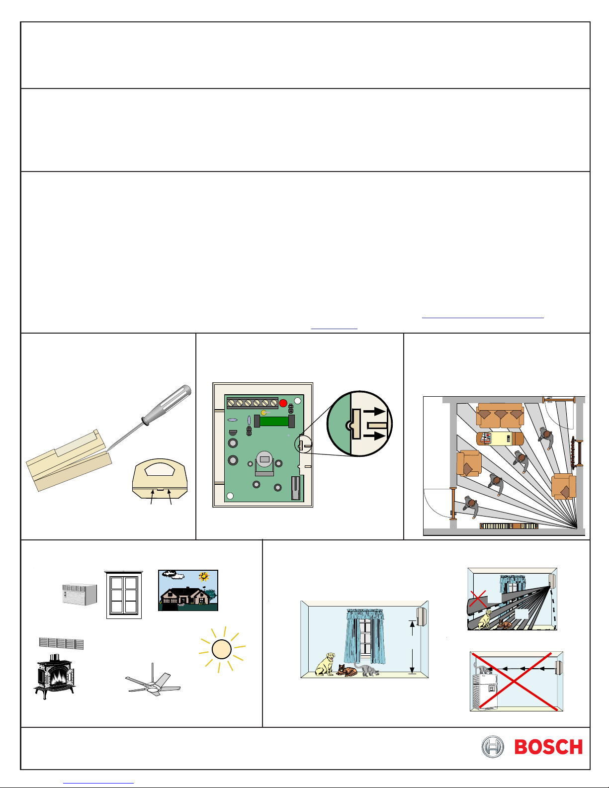
3.0 Installation
3.1 Remove the cover using
a small flat-blade
screwdriver.
Bottom of Detector
3.2 Press the vertical adjust tab
toward the side of the case and
lift out the board.
LED
7.5-9ft
• Temperature: -20° to +120°F (-29° to +49°C). For UL Listed
Product Installations, the temperature range is
+32° to +120°F (0° to +49°C).
• Humidity: 0 - 85% non-condensing.
• Dimensions: 3 in. H x 2.25 in. W x 1.5 in. D
(7.6 cm x 5.7 cm x 3.8 cm)
• Options: B335 Swivel Mounting Bracket. Use of this bracket
may decrease the PIR range and increase dead
zones.
•
Reading Bosch Security Systems, Inc. Product Date Codes
For Product Date Code information, refer to the Bosch Security
Systems, Inc. Web site at: http://www.boschsecurity.com/
datecodes/
3.3 Select a mounting location.
Mount the sensor where an
intruder will most likely cross
through the coverage pattern.
ON
Insert screwdriver here or here
3.4 Avoid.
Direct Hot or
Cold
Drafts
Air
Conditioning
Outlets
Windows
Uninsulated
Heat
Sources
and
Walls
Moving Object s
Direct Sunlight
Mounting
Outdoors
3.5 Observe the pet immunity mounting recommendations.
Note: The upper areas are not
pet immune.
NO
OK
7.5 - 9 ft.
(2.25 - 2.7 m)
Don't point where pets ca n cl im b
Mount the detec tor 7.5 - 9 feet
(2.25 - 2.7 meters) above the floor
NO
Pet
Immune
Area
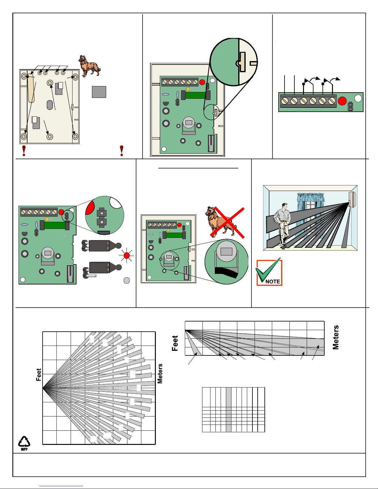
3.6 Mount the detector .
Note:To avoid possible circuit board damage,
use only the mounting hardware
provided in the appropriate punch-out
mounting holes.
Thinwall knockouts
for wiring
Corner Mount
=
Remove
7.5 - 9 Ft
(2.25 - 2.7 m)
3.7 Snap the board into the clip so that
the notch aligns with the tab on the
clip.
7.5-9ft
LED
ON
3.8 Wire the Detector .
(DS940PT
only)
9-15
VDC
-
Alarm
Contacts
+
Tamper
Contacts
Areas
if using the
Surface
Mount
Don't overtighten the mounting screws
Cover may not attach correctly
B335 Bracket
Do not use
the B335
Bracket in
pet
applications
3.9 Select LED Operation
LED
ON
7.5-9ft
ON
OFF
ON
3.10
In non-pet applications only ,
if look-down is desired, peel
away the look-down masks. Do
not remove the clear plastic
lens.
LED
ON
7.5-9ft
7.5-9ft
Peel away
the mask
LED
ON
Normally Closed (NC) contacts
4.0 Walk T est. Perform the W alk T est
at the time of installation and
annually thereafter.
This detector contains an environmental sta-
bilization circuit which requires
approximately 2 minutes after
initial power-up to warm up.
During this time the detector will
not respond to any movement.
Please wait 2 minutes after initial power-
up to perform any walk tests.
5.0 Coverage Patterns
Meters
0
20
1
2
3
10
4
0
10
8
9
10
20
Feet
0
© 2011 Bosch Security Systems, Inc.
130 Perinton Parkway, Fairport, New York 14450
www.boschsecurity.com
10
11
20
30
Meters
0
12
20
7.5
6
0
20
0
Feet
Look
5
6
0
Down
1234567891011
67-7756-
66
4555
2010
3444
7
12 22
23 33
34 44
45 55
56 66
67 77
DS940P Lens
(inside view)
40
6
30
23-
12-221-
33
Although generally not required, if
masking is desired, the lens diagram
shows the appropriate areas to be
masked (see shaded area on the
DS940P lens diagram). Use an
opaque material (such as, electrical
tape) to mask the desired areas.
DS940P/DS940PT Installation Instructions
P/N: F01U035202-07 Page 2
12
6
0
6
40
11
2/11
 Loading...