

Installation Instructions
for the
DS7432 Eight Input Remote Module
1.0 Description
The DS7432 is an Eight Input Remote Module that provides a means
of addressing up to eight input loops of conventional contacts to the
multiplex bus of the control.
2.0 Specifications
• Control Panel Requirements: The DS7432 is designed to work
with the following control panels:
• A DS7400, DS7400X, DS7400Xi, DS7400Xi Rev. 3 or
DS7400Xi Rev . 4.
• Up to 7 DS7432s can be used per DS7400 system.
• Up to 15 DS7432 modules are allowed on DS7400X, Xi and
Xi Rev. 3.
• The DS7400Xi Rev. 4 control panel can support up to 30
DS7432 modules.
• One DS7430, DS7436 or DS9431 Multiplex Expansion Module
is required in the system to use the DS7432 Remote Module.
• Current Draw: 10 mA Standby , 10 mA Alarm
• Minimum Bus Volt age For Operation: 8 VDC peak
• Wiring: Refer to the reference guide for the panel’s multiplex
expansion module for multiplex wiring requirements. The length of
the wire connected to the loop inputs on the DS7432 must be less
than 250 ft. (76 m) per loop.
• The recommended wiring to the control is standard #18 (1.22 mm)
or #22 (0.74 mm) A WG , quad (4-wire) cable. Do not use shielded
or twisted pair cable.
• For fire applications, #18 A WG (1.2 mm) wire is required.
If using separate powered detectors (other than
smoke detectors) with a DS7400 Series Control/
Communicator, the DS7432 can be powered from the
control panel auxiliary power (terminals 7 and 8). The
detector can be connected to the DS7432 (see Figure
4). This eliminates the need for home-run power
wiring from each detector to the control when the
DS7432 is mounted outside of the enclosure.
Be sure all wiring is unpowered before routing.
If the wiring is to enter through the rear of the enclosure, open the
DS7432's rear wire entrance. If the wiring is to run along the surface of
the enclosure, open the DS7432's surface wire entrance. See Figure 2.
4.0 Programming
4.1 System Programming
Refer to the System Programming section in your panel’s reference guide
for Zone programming information.
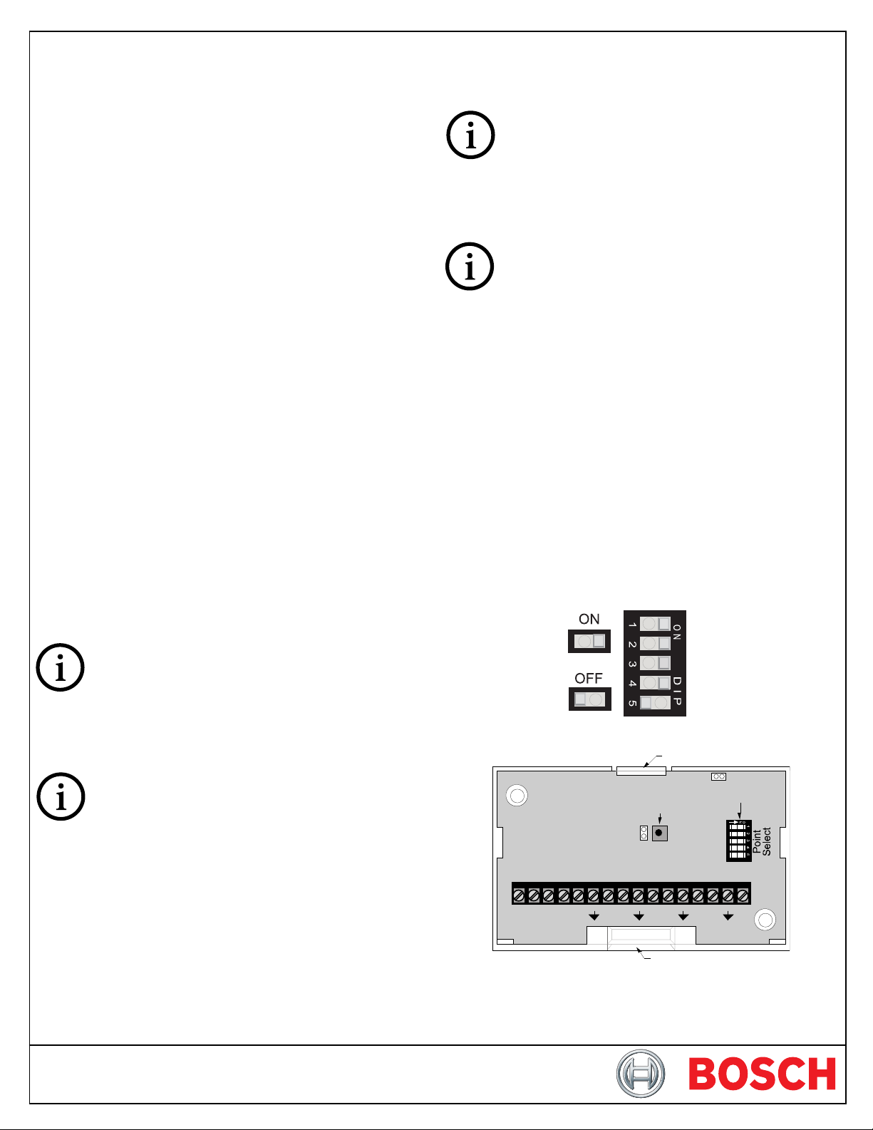
4.1 DIP Switch Settings
The DIP switches select which zones will be activated by the loop inputs.
Set the DIP switches as shown in Table 1 (Page 2).
• No two DS7432s should be set the same.
• The DS7432 occupies eight zones when connected to the control
panel. The input loops of the DS7432 correspond to the zones of
the control as shown in Table 2.
3.0 Installation
P3 of the DS7432 is for European application only. Do
not put a jumper here.
P2 of the DS7432 allows the tamper switch to be bypassed with a jumper
when testing or servicing.
Remove jumper P2 when testing or servicing has
been completed.
Use the mounting holes (upper left and lower right corners) to mount. It
can be mounted inside or outside of the control enclosure.
Route wiring as necessary from the DS7430, DS7436 or DS9431 in the
control enclosure and from the remote devices to the DS7432.
Connect wiring as shown in Figure 3.
Figure 1: DIP Switch Orientation
+–+–12345678
POWER BUS
Figure 2: DS7432 Front View Without Cover
Rear Wire Entrance
Locking tab
Tamper Switch
P2
Surface Wire Entrance
P3
DIP switch

sehctiwSPID
senoZ 1 2 3 4 5
61-9ffOffOffOffOnO
42-71ffOffOffOnOffO
23-52ffOffOffOnOnO
04-33ffOffOnOffOffO
84-14ffOffOnOffOnO
rebmuNenoZ
tupnI2347SD
pooL
61-9senoZ901112131415161
42-71senoZ7181910212223242
23-52senoZ5262728292031323
04-33senoZ3343536373839304
84-14senoZ1424344454647484
65-94senoZ94051
1 2 3 4 5 6 7 8
52535455565
65-94ffOffOnOnOffO
46-75ffOffOnOnOnO
27-56ffOnOf
fOffOffO
08-37ffOnOffOffOnO
88-18ffOnOffOnOffO
69-98ffOnOffOnOnO
401-79ffOnOnOffOffO
211-501ffOnOnOffOnO
021-311ffOnOnOnOffO
821-121ffOnOnOnOnO
63
1-921nOffOffOffOffO
441-731nOffOffOffOnO
251-541nOffOffOnOffO
061-351nOffOffOnOnO
861-161nOffOnOffOffO
671-961nOffOnOffOnO
481-771nOffOnOnOffO
291-581nOffOnOnOnO
002-391nOnOffOffOffO
46-75senoZ7585950616263646
27-56senoZ5666768696071727
08-37senoZ3747576777879708
88-18senoZ1828384858687888
69-98senoZ9809192939495969
9senoZ798999001101201301401
401-7
211-501senoZ501601701801901011111211
021-311senoZ311411511611711811911021
821-121senoZ1212213214215216217218
631-921senoZ921031131231331431531631
441-731senoZ731831931041141241341441
251-541senoZ541641741841941051151251
061-351senoZ35145
861-161senoZ161261361461561661761861
671-961senoZ961071171271371471571671
481-771senoZ771871971081181281381481
581senoZ581681781881981091191291
291002-391senoZ391491591691791891991002
802-102senoZ102202302402502602702802
612-902senoZ90201211221231
422-712senoZ712812912022122222322422
232-522senoZ522622722822922032132232
1551651751851951061
2412512612
21
802-102nOnOffOffOnO
612-902nOnOffOnOffO
oZ142242342442542642742842
042-332senoZ332432532632732832932042
842-142sen
652-942senoZ942052152252352452552652
422-712nOnOffOnOnO
232-522nOnOnOffOffO
Table 2: Loop/Zone Number Relationship
042-332nOnOnOffOnO
842-1
42nOnOnOnOffO
652-942nOnOnOnOnO
Table 1: DIP Switch Settings
Points 249 - 256 are not
available for DS9400 use.
Page 2 © 2011 Bosch Security Systems, Inc. DS7432 Installation Instructions
 Loading...