

Bosch DIP-6043-4HD User Manual
DIVAR IP 6000 1U
DIP-6040-00N, DIP-6042-4HD
en Installation manual


DIVAR IP 6000 1U Table of Contents | en 3
Table of contents
1
1.1 General safety precautions 5
1.2 Electrical safety precautions 6
1.3 ESD precautions 7
1.4 Operating precautions 7
1.5 Important notices 8
1.6 FCC and ICES compliance 8
2
2.1 Chassis features 9
2.2 Chassis components 9
2.2.1 Chassis 9
2.2.2 Backplane 10
2.2.3 Fans 10
2.2.4 Mounting rails 10
2.2.5 Power supply 10
2.2.6 Air shroud 10
2.3 System interface 10
2.3.1 Control panel buttons 11
2.3.2 Control panel LEDs 11
2.3.3 Drive carrier LEDs 12
2.3.4 Power supply LEDs and overheat indicators 12
2.3.5 Overheating 13
3
3.1 Removing the chassis cover 14
3.2 Installing hard drives 14
3.2.1 Removing hard drive trays 14
3.2.2 Installing a hard drive 15
3.3 Installing a DVD-ROM or floppy drive 17
3.4 Replacing the internal transcoder device 17
3.5 Installing the motherboard 18
3.6 Installing the air shroud 18
3.7 System fans 19
3.8 Power supply 20
3.8.1 Power supply failure 20
4
4.1 Unpacking the system 22
4.2 Preparing for setup 22
4.2.1 Choosing a setup location 22
4.2.2 Rack precautions 22
4.2.3 General system precautions 23
4.2.4 Rack mounting considerations 23
4.3 Rack mounting instructions 23
4.3.1 Identifying the sections of the rack rails 24
4.3.2 Installing the inner rails 24
4.3.3 Assembling the outer rails 25
4.3.4 Installing the outer rails to the rack 25
4.3.5 Installing the chassis into the rack 26
Safety precaution 5
System overview 9
Chassis setup and maintenance 14
Rack installation 22
Bosch Sicherheitssysteme GmbH Installation manual 2013.05 | V1 | DOC

4 en | Table of Contents DIVAR IP 6000 1U
4.3.6 Installing the chassis into a Telco rack 27
4.4 Turning on the system 27
5
Appendix 28
5.1 Motherboard 28
5.1.1 Motherboard layout 28
5.1.2 Motherboard component overview 29
5.1.3 Motherboard features 31
5.1.4 Block diagram 33
5.2 Chipset overview 33
5.3 PC health monitoring 34
5.4 Power configuration settings 34
5.5 Power supply 35
5.6 Super I/O 35
5.7 iSCSI support 35
5.8 Overview of the Nuvoton BMC controller 36
5.9 RAID disaster recovery 36
5.9.1 Multiple disks failed - theory 37
5.9.2 Multiple disks failed - practice 42
5.9.3 Foreign configuration disk appears in the Windows GUI after booting 45
5.9.4 MegaCLI Commandline Utility 46
2013.05 | V1 | DOC Installation manual Bosch Sicherheitssysteme GmbH
!
!
!
DIVAR IP 6000 1U Safety precaution | en 5
1
1.1
Safety precaution
Observe the safety precautions in this chapter.
General safety precautions
Follow these rules to ensure general safety:
– Keep the area around the system clean and free of clutter.
– Place the chassis top cover and any system components that have been removed away
from the system or on a table so that they won't accidentally be stepped on.
– While working on the system, do not wear loose clothing such as neckties and
unbuttoned shirt sleeves, which can come into contact with electrical circuits or be
pulled into a cooling fan.
– Remove any jewelry or metal objects from your body, which are excellent metal
conductors that can create short circuits and harm you if they come into contact with
printed circuit boards or areas where power is present.
– After accessing the inside of the system, close the system back up and secure it to the
rack unit after ensuring that all connections have been made.
– The system weighs approximately 38.5 lbs. (17.5 kg) when fully loaded. When lifting the
system, two people at either end should lift slowly with their feet spread out to distribute
the weight. Always keep your back straight and lift with your legs.
Warning!
Interruption of mains supply:
Voltage is applied as soon as the mains plug is inserted into the mains socket.
However, for devices with a mains switch, the device is only ready for operation when the
mains switch (ON/OFF) is in the ON position. When the mains plug is pulled out of the
socket, the supply of power to the device is completely interrupted.
Warning!
Removing the housing:
To avoid electric shock, the housing must only be removed by qualified service personnel.
Before removing the housing, the plug must always be removed from the mains socket and
remain disconnected while the housing is removed. Servicing must only be carried out by
qualified service personnel. The user must not carry out any repairs.
Warning!
Power cable and AC adapter:
When installing the product, use the provided or designated connection cables, power cables
and AC adaptors. Using any other cables and adaptors could cause a malfunction or a fire.
Electrical Appliance and Material Safety Law prohibits the use of UL or CSA-certified cables
(that have UL/CSA shown on the code) for any other electrical devices.
Bosch Sicherheitssysteme GmbH Installation manual 2013.05 | V1 | DOC
!
!
6 en | Safety precaution DIVAR IP 6000 1U
Warning!
Lithium battery:
Batteries that have been inserted wrongly can cause an explosion. Always replace empty
batteries with batteries of the same type or a similar type recommended by the manufacturer.
Handle used batteries carefully. Do not damage the battery in any way. A damaged battery
may release hazardous materials into the environment.
Dispose of empty batteries according to the manufacturer's instructions.
Warning!
Handling of lead solder materials used in this product may expose you to lead, a chemical
known to the State of California to cause birth defects and other reproductive harm.
Notice!
Electrostatically sensitive device:
To avoid electrostatic discharges, the CMOS/MOSFET protection measures must be carried
out correctly.
When handling electrostatically sensitive printed circuits, grounded anti-static wrist bands
must be worn and the ESD safety precautions observed.
1.2
Notice!
Installation should only be carried out by qualified customer service personnel in accordance
with the applicable electrical regulations.
Disposal
Your Bosch product has been developed and manufactured using highquality materials and components that can be reused.
This symbol means that electronic and electrical devices that have reached
the end of their working life must be disposed of separately from
household waste.
In the EU, separate collecting systems are already in place for used
electrical and electronic products. Please dispose of these devices at your
local communal waste collection point or at a recycling center.
Electrical safety precautions
Basic electrical safety precautions should be followed to protect you from harm and the
system from damage:
– Be aware of the locations of the power on/off switch on the chassis as well as the room's
emergency power-off switch, disconnection switch or electrical outlet. If an electrical
accident occurs, you can then quickly remove power from the system.
– Do not work alone when working with high voltage components.
– Power should always be disconnected from the system when removing or installing main
system components, such as the motherboard or memory modules. When disconnecting
power, you should first turn off the system and then unplug the power cords from all the
power supply modules in the system.
– When working around exposed electrical circuits, another person who is familiar with the
power-off controls should be nearby to switch off the power if necessary.
2013.05 | V1 | DOC Installation manual Bosch Sicherheitssysteme GmbH
!
!
DIVAR IP 6000 1U Safety precaution | en 7
– Use only one hand when working with powered-on electrical equipment. This is to avoid
making a complete circuit, which will cause electrical shock. Use extreme caution when
using metal tools, which can easily damage any electrical components or circuit boards
they come into contact with.
– The power supply power cords must include a grounding plug and must be plugged into
grounded electrical outlets. The unit has more than one power supply cord. Disconnect
both power supply cords before servicing to avoid electrical shock.
– Mainboard replaceable soldered-in fuses: Self-resetting PTC (Positive Temperature
Coefficient) fuses on the mainboard must be replaced by trained service technicians only.
The new fuse must be the same or equivalent as the one replaced. Contact technical
support for details and support.
Caution!
Mainboard Battery: There is a danger of explosion if the onboard battery is installed upside
down, which will reverse its polarities. This battery must be replaced only with the same or
an equivalent type recommended by the manufacturer (CR2032). Dispose of used batteries
according to the manufacturer's instructions.
Caution!
DVD-ROM Laser: This system comes without a DVD-ROM drive but if added: To prevent direct
exposure to the laser beam and hazardous radiation exposure, do not open the enclosure or
use the unit in any unconventional way.
1.3
ESD precautions
Electrostatic Discharge (ESD) is generated by two objects with different electrical charges
coming into contact with each other. An electrical discharge is created to neutralize this
difference, which can damage electronic components and printed circuit boards. The
following measures are generally sufficient to neutralize this difference before contact is made
to protect your equipment from ESD:
– Do not use mats designed to decrease electrostatic discharge as protection from
electrical shock. Instead, use rubber mats that have been specifically designed as
electrical insulators.
– Use a grounded wrist strap designed to prevent static discharge.
– Keep all components and printed circuit boards (PCBs) in their antistatic bags until ready
for use.
– Touch a grounded metal object before removing the board from the antistatic bag.
– Do not let components or printed circuit boards come into contact with your clothing,
which may retain a charge even if you are wearing a wrist strap.
– Handle a board by its edges only. Do not touch its components, peripheral chips, memory
modules or contacts.
– When handling chips or modules, avoid touching their pins.
– Put the mainboard and peripherals back into their antistatic bags when not in use.
– For grounding purposes, make sure your computer chassis provides excellent
conductivity between the power supply, the case, the mounting fasteners and the
mainboard.
1.4
Bosch Sicherheitssysteme GmbH Installation manual 2013.05 | V1 | DOC
Operating precautions
The chassis cover must be in place when the system is operating to assure proper cooling. Out
of warranty damage to the system can occur if this practice is not strictly followed.
8 en | Safety precaution DIVAR IP 6000 1U
Note:
Please handle used batteries carefully. Do not damage the battery in any way. A damaged
battery may release hazardous materials into the environment. Do not discard a used battery
in the garbage or a public landfill. Please comply with the regulations set up by your local
hazardous waste management agency to dispose of your used battery properly.
1.5
1.6
Important notices
Accessories - Do not place this unit on an unstable stand, tripod, bracket,
or mount. The unit may fall, causing serious injury and/or serious damage to
the unit. Use only with the cart, stand, tripod, bracket, or table specified by
the manufacturer. When a cart is used, use caution and care when moving
the cart/apparatus combination to avoid injury from tip-over. Quick stops,
excessive force, or uneven surfaces may cause the cart/unit combination to
overturn. Mount the unit per the manufacturer's instructions.
FCC and ICES compliance
(only for U.S.A. and Canada)
This equipment has been tested and found to comply with the limits for a Class A digital
device pursuant to Part 15 of the FCC Rules. These limits are designed to provide reasonable
protection against harmful interference when the equipment is operated in a commercial
environment. This equipment generates, uses, and can radiate radio frequency energy and, if
not installed and used in accordance with the manufacturer’s instruction manual, may cause
harmful interference with radio communications. Operation of this equipment in a residential
area is likely to cause harmful interference, in which case you will be required to correct the
interference at your own expense.
2013.05 | V1 | DOC Installation manual Bosch Sicherheitssysteme GmbH

DIVAR IP 6000 1U System overview | en 9
2
System overview
DIVAR IP 6000 is an affordable, simple and reliable all-in-one recording management solution
for network surveillance systems of up to 64 cameras. Powered by VRM (Video Recording
Manager) software, the system is an intelligent IP storage device that eliminates the need for
separate NVR (Network Video Recorder) server and storage hardware.
The 1U rack mount unit combines advanced recording management and state-of-the-art iSCSI
storage into a single cost-effective, plug and play IP recording appliance for IT-minded
customers seeking for a state-of-the-art “second generation” NVR recording solution.
The DIVAR IP 6000 1U chassis features a unique and highly-optimized design. The chassis is
equipped with high efficiency power supply.
High performance fans provide ample optimized cooling for memory modules. Hot-swap drive
bays offer maximum storage capacity in a 1U form factor.
DIVAR IP 6000 features:
– Instant real time access to video
View high quality HD video despite low or limited bandwidth connections. Dynamic
Transcoding technology ensures that you can view your video immediately — anytime,
anywhere.
– Remote viewing
DIVAR IP 6000 comes with our advanced Video Client for remote viewing. Video Client is a
Windows PC application for live viewing and playback including Configuration Manager.
Configuration Manager allows the settings of the DIVAR IP 6000 be configured. A stand-
alone archive player will allow archive playback and authentication without any other
workstation software.
For information on supported hardware, see the datasheet for DIVAR IP 6000 in the Bosch
Online Product Catalog.
2.1
2.2
2.2.1
Chassis features
The DIVAR IP 6000 1U high performance chassis includes the following features:
– CPU
The chassis supports a Dual-core Xeon processor.
– Hard Drives
The chassis features 4 slots for SATA drives. These drives are hot swappable. Once setup
correctly, these drives can be removed without turning off the unit. In addition, these
drives support SES2 (SAS/SATA).
– Other Features
Other onboard features are included to promote system health. These include various
4 cooling fans, a convenient power switch, reset button, and 5 LED indicators.
Chassis components
This chapter describes the most common components included with your chassis. For more
information, see the installation instructions detailed later in this manual.
Chassis
The chassis includes 1 slim CD-ROM bay and 4 hard drive bays. The chassis accepts a 1U
backplane, 4 fans and 2 power supplies.
Bosch Sicherheitssysteme GmbH Installation manual 2013.05 | V1 | DOC
!
10 en | System overview DIVAR IP 6000 1U
2.2.2
2.2.3
2.2.4
2.2.5
Backplane
Each chassis comes with a 1U backplane. The backplane accepts SAS/SATA or SCSI hard
drives.
Warning!
Use caution when servicing and working around the backplane. Hazardous voltage or energy
is present on the backplane when the system is operating. Do not touch the backplane with
any metal objects and make sure no ribbon cables touch the backplane.
Fans
The chassis supports 4 system fans that are powered from the motherboard. These fans are
1U high and are powered by 3-pin connectors.
Mounting rails
The unit can be placed in a rack for secure storage and use. To setup your rack, follow the
step-by-step instructions included in this manual.
Power supply
Each chassis model includes 2 high-efficiency power supplies (redundant). In the unlikely
event your power supply fails, replacement is simple and can be accomplished without tools.
2.2.6
2.3
Air shroud
Air shrouds are shields, usually plastic, which conduct the airflow directly to where it is
needed. Always use the air shroud included with your chassis.
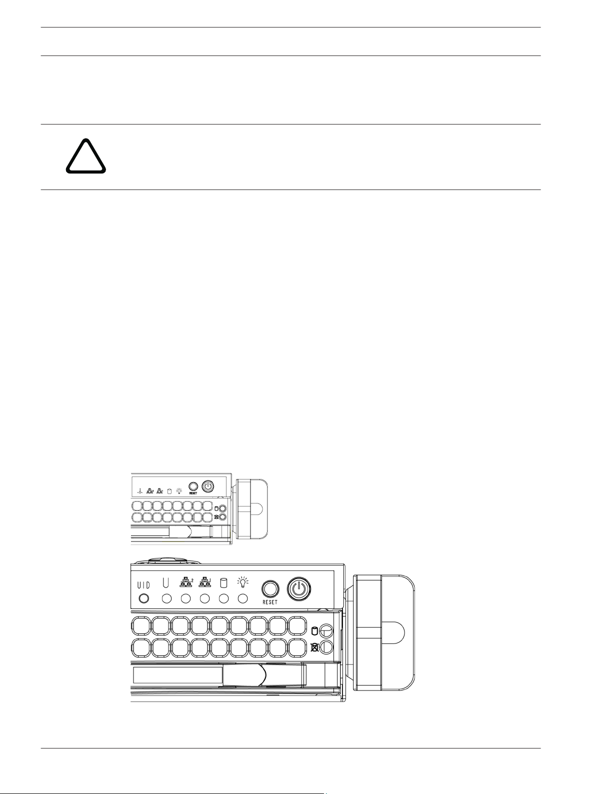
System interface
There are several LEDs on the front and rear of the chassis. The LEDs show the over-all status
of the system and the activity and health of specific components.
2013.05 | V1 | DOC Installation manual Bosch Sicherheitssysteme GmbH
DIVAR IP 6000 1U System overview | en 11
2.3.1
2.3.2
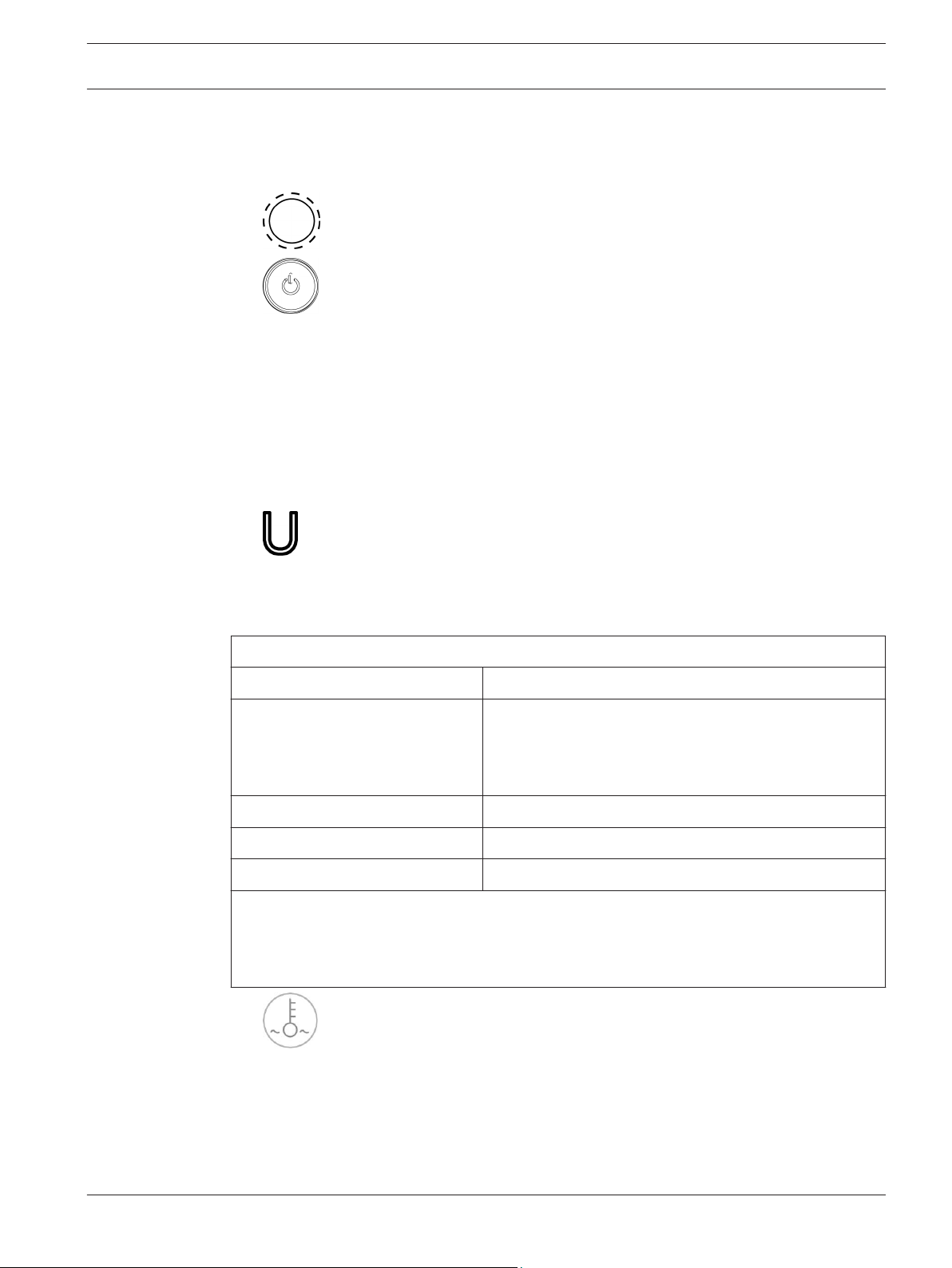
Control panel buttons
The chassis includes two or three push-buttons located on the front panel: a reset button, a
power on/off button, and a UID button.
–
–
supply to the server system. Turning off system power with this button removes the main
power but keeps standby power supplied to the system. Therefore, you must unplug
system before servicing.
Reset: The reset button is used to reboot the system.
Power: The main power switch is used to apply or remove power from the power
Control panel LEDs
The control panel located on the front of the chassis has up to 5 LEDs. These LEDs provide
critical information related to different parts of the system. This section explains what each
LED indicates when illuminated and any action that may be required.
–
Universal Information LED: The Universal Information LED is used to indicate fan
failure, power failure, overheat condition, or to identify the unit within a large rack
installation. The feature requires a motherboard that supports the Universal Information
LED.
Universal Information LED States
Fast blinking red (1x/sec) Fan failure
Solid red CPU overheat
Note: Can be caused by cables obstructing the airflow in
the system or the ambient room temperature being too
warm.
Slow blinking red (1x/4 sec) Power failure
Solid blue Local UID button depressed
Blinking blue IPMI-activated UID
Note:
Deactivating the UID LED must be performed in the same way it was activated. If the UID
LED was activated via IPMI, you can only turn the LED off via IPMI and not with the UID
button.
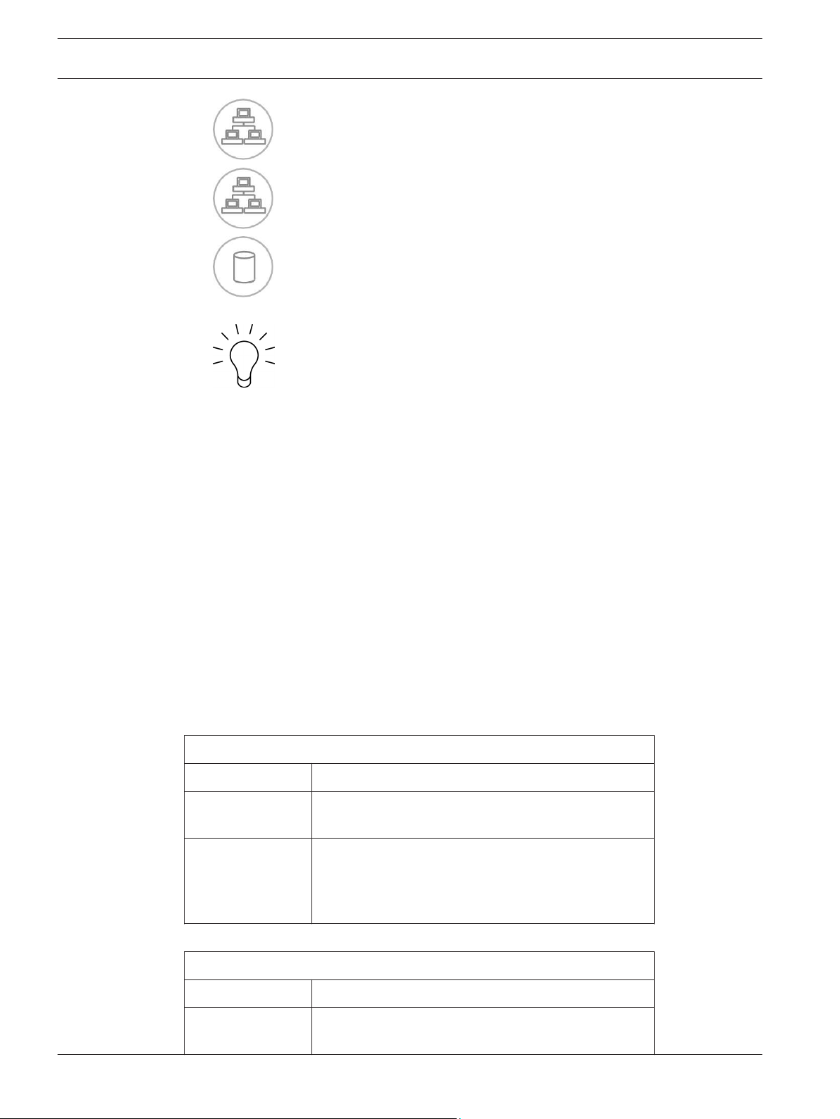
– Overheat/fan fail: A flashing LED indicates a fan failure.
When continuously on (not flashing) the LED indicates an overheat condition, which may
be caused by cables obstructing the airflow in the system or the ambient room
temperature being too warm. Check the routing of the cables and make sure all fans are
present and operating normally. You should also check to make sure that the chassis
covers are installed. Finally, verify that the heat sinks are installed properly.
This LED will remain flashing or on as long as the fan failure/overheat condition exists.
Bosch Sicherheitssysteme GmbH Installation manual 2013.05 | V1 | DOC
12 en | System overview DIVAR IP 6000 1U
– NiC2: A flashing LED indicates network activity on GLAN2.
2.3.3
–
– HDD: A flashing LED indicates IDE channel activity in the SAS/SATA drive, SCSI
drive, and/or DVD-ROM drive activity.
– Power: Indicates power is being supplied to the system's power supply units.
This LED should normally be illuminated when the system is operating.
NIC1: A flashing LED indicates network activity on GLAN1.
Drive carrier LEDs
Your chassis uses SAS/SATA.
SAS/SATA drives
Each SAS/SATA drive carrier has two LEDs.
– Green: Each Serial ATA drive carrier has a green LED. When illuminated, this green LED
(on the front of the SATA drive carrier) indicates drive activity. A connection to the SATA
backplane enables this LED to blink on and off when that particular drive is being
accessed.
– Red: The red LED indicates a SAS/SATA drive failure. If one of the SAS/SATA drives fail,
you should be notified by your system management software.
2.3.4
Power supply LEDs and overheat indicators
This chassis provides several options which may include hot-swappable, cold-swappable, and
redundant power supplies. Some power supplies include an LED in the rear with the following
definitions:
450 W and 650 W power supplies
450 W and 650 W power supply LEDs
Solid green Power supply is on.
Solid amber The power supply is plugged in and turned off, or the
system is off but in an abnormal state.
Blinking amber Power supply temperature has reached to 63” C. The
system automatically turns off when the power supply
temperature reaches 70” C and restarts when the
power supply temperature is below 60” C.
All other power supplies
All other power supply LEDs
Solid green Power supply is on.
Solid amber The power supply is plugged in and turned off, or the
system is off but in an abnormal state.
2013.05 | V1 | DOC Installation manual Bosch Sicherheitssysteme GmbH

DIVAR IP 6000 1U System overview | en 13
2.3.5
Overheating
The section lists actions that should be taken in the unlikely event the server overheats.
Overheat temperature setting
Some backplanes allow the overheat temperature to be set at 45, 50, or 55 by changing a
jumper setting.
If the server overheats, do the following:
1. Use the LEDs to determine the nature of the overheating condition.
2. Confirm that the chassis covers are installed properly.
3. Check the routing of the cables and make sure all fans are present and operating
normally.
4. Verify that the heatsinks are installed properly.
Bosch Sicherheitssysteme GmbH Installation manual 2013.05 | V1 | DOC
!
14 en | Chassis setup and maintenance DIVAR IP 6000 1U
3
3.1
Chassis setup and maintenance
This chapter covers the steps required to install components and perform maintenance on the
chassis.
Caution!
Review the warnings and precautions listed in the manual before setting up or servicing this
chassis.
Removing the chassis cover
3.2
3.2.1
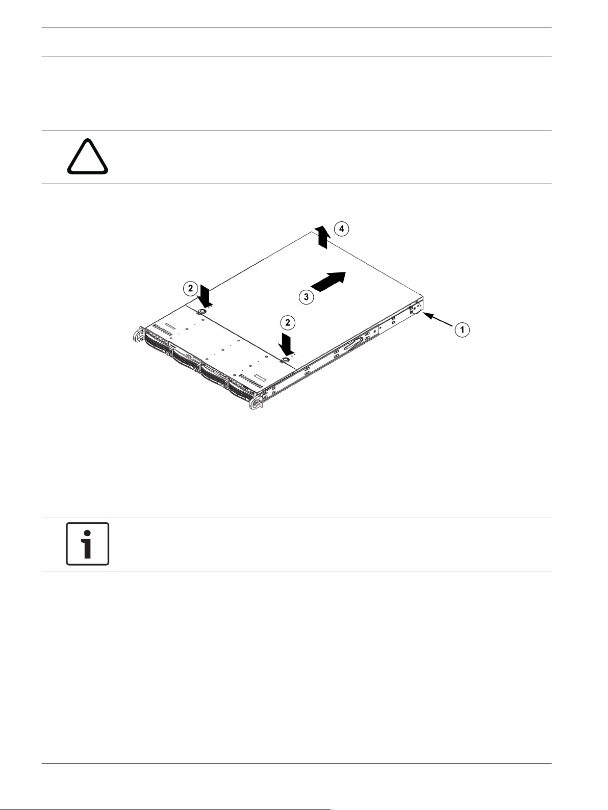
To remove the chassis cover:
1. Remove the two screws on each side of the cover, which secure the cover to the chassis.
2. Press the release tabs to remove the cover from the locked position. Press both tabs at
the same time.
3. Once the top cover is released from the locked position, slide the cover toward the rear
of the chassis.
4. Lift the cover off the chassis.
Notice!
Except for short periods of time, do NOT operate the server without the cover in place. The
chassis cover must be in place to allow proper airflow and prevent overheating.
Installing hard drives
This chapter describes the removing and installing of hard drives.
Removing hard drive trays
The drives are mounted in drive carriers to simplify their installation and removal from the
chassis. These carriers also help promote proper airflow for the drive bays.
2013.05 | V1 | DOC Installation manual Bosch Sicherheitssysteme GmbH
DIVAR IP 6000 1U Chassis setup and maintenance | en 15
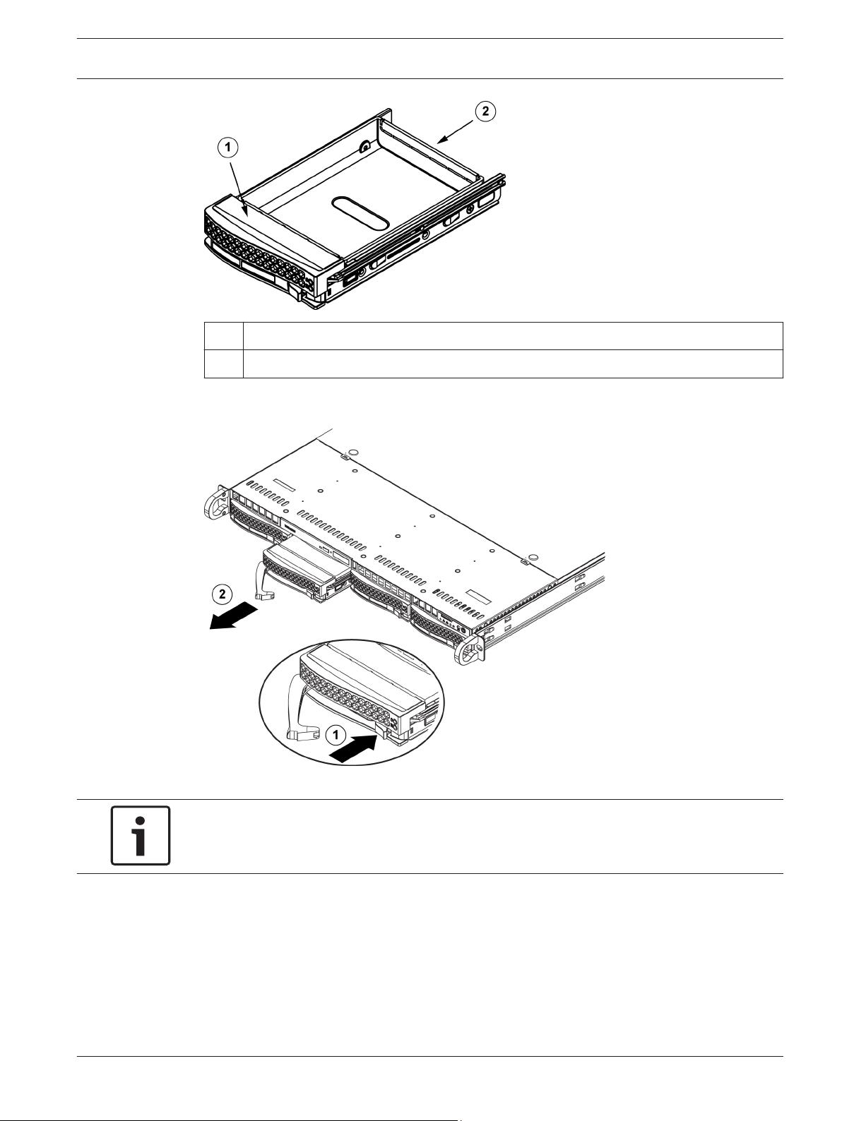
1 Drive carrier
2 Dummy drive
To remove hard drive trays from the chassis:
1. Press the release button on the drive carrier. This extends the drive carrier handle.
2. Use the handle to pull the drive out of the chassis.
Notice!
Except for short periods of time (swapping hard drives), do not operate the unit with the
hard drives removed from the bays.
3.2.2
Bosch Sicherheitssysteme GmbH Installation manual 2013.05 | V1 | DOC
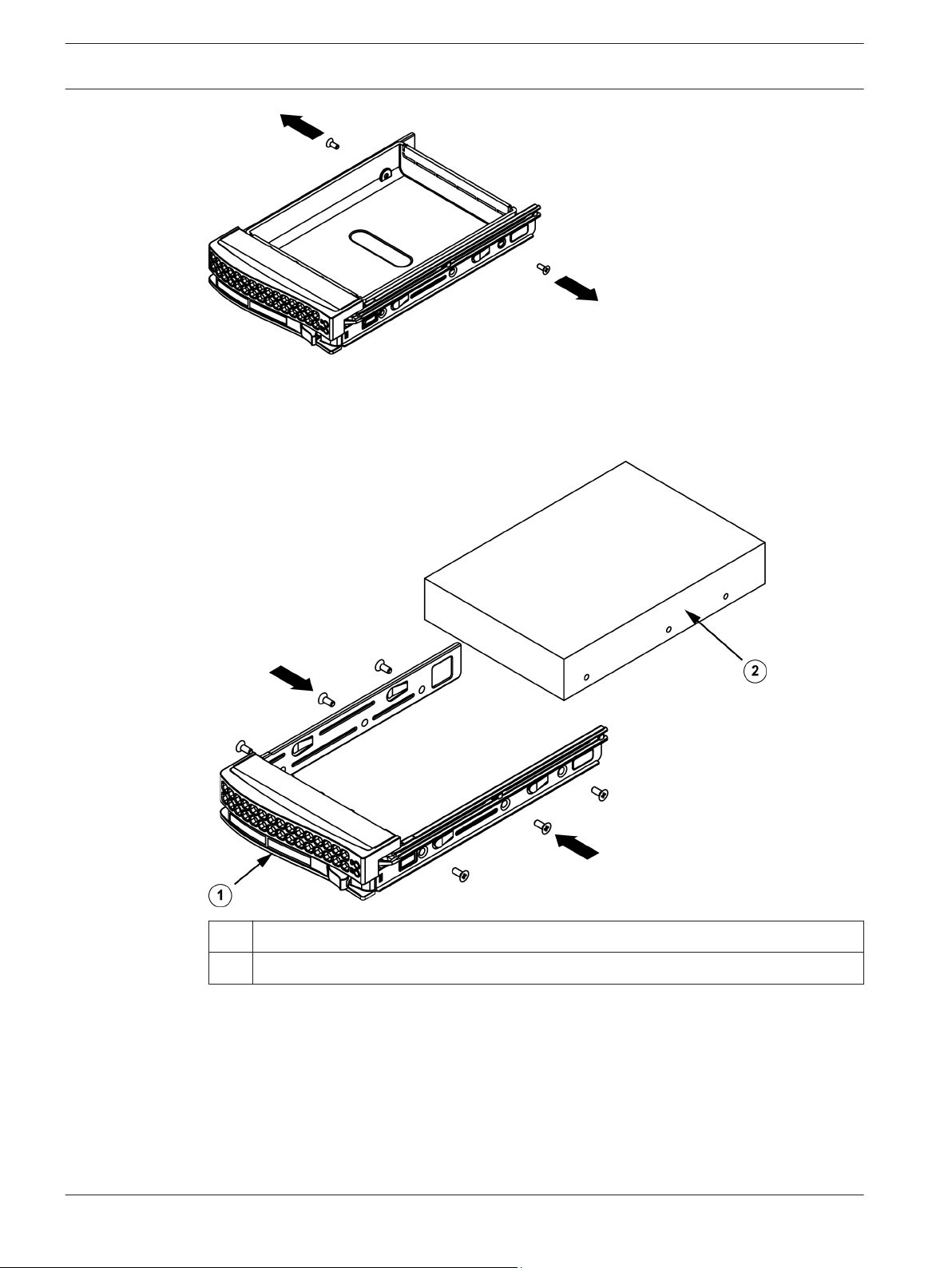
Installing a hard drive
The drives are mounted in drive carriers.
To install a hard drive to the hard drive carrier:
1. Remove the screws securing the dummy drive to the carrier.
en | Chassis setup and maintenance DIVAR IP 6000 1U
16
2. Remove the dummy drive from the carrier.
3. Install a new drive into the carrier with the printed circuit board side facing down so that
the mounting holes align with those in the carrier.
4. Secure the hard drive by tightening all 6 screws.
1
Drive carrier
2 SAS/SATA hard drive
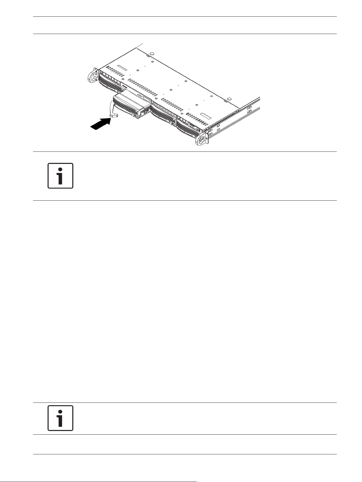
5. Replace the drive carrier into the chassis bay. Make sure that the drive carrier handle is
completely closed.
2013.05 | V1 | DOC Installation manual Bosch Sicherheitssysteme GmbH
DIVAR IP 6000 1U Chassis setup and maintenance | en 17
Notice!
We recommend using the respective Bosch hard disk drives. The hard disk drives as one of
the critical component are carefully selected by Bosch based on available failure rates. HDD –
not delivered from Bosch – are not supported. Information on supported HDDs can be found
in the datasheet in the Bosch Online Product Catalog.
3.3
3.4
Installing a DVD-ROM or floppy drive
The Bosch models come without a DVD-ROM. Due to the Bosch specific setup a DVD-ROM
drive is not needed for operations and / or maintenance.
To install or replace a DVD-ROM or floppy drive:
1. Turn off the system and if necessary, remove the unit from the rack and the front bezel
from the chassis.
2. Remove the chassis cover.
3. Unplug the drives power and data cables from the motherboard and/or backplane.
4. If you are adding a new drive:
Remove the mini-bezel (grate) from the drive bay. The bezel can be removed by pulling
out the hard drive beneath the DVD-ROM or floppy drive bay, then pulling the mini-bezel
forward.
If you are replacing a drive:
Locate the locking tab at the rear (left hand side when viewed from the front) of the DVDROM or floppy drive. Push the tab toward the drive and push the drive unit out the front
of the chassis.
5. Insert the new drive unit in the slot until the tab locks in place.
6. Reconnect the data and power cables.
7. Replace the chassis cover. replace the unit in the rack, if necessary, then turn on the
system.
Replacing the internal transcoder device
The chassis model includes an internal USB transcoder device.
Notice!
To replace or install the transcoder device, please apply to one of the Bosch RMA helpdesks.
Bosch Sicherheitssysteme GmbH Installation manual 2013.05 | V1 | DOC
 Loading...