

Bosch Diniop IP Installation Manual
Dinion IP - NWC-0455
Installation Manual
IP Camera
EN

Bosch Security Systems | 2006-05
Dinion IP | Installation Manual
ii
Copyright
This user guide is the intellectual property of Bosch Security Systems and is protected
by copyright. All rights reserved. No part of this document may be reproduced or
transmitted for any purpose, by whatever means, electronic or mechanical, without the
express written permission of Bosch Security Systems.
Release: May 2006 (Software version 2.0)
© Copyright 2006 Bosch Security Systems
Note
This user guide has been compiled with great care and the information it contains has
been thoroughly verified. The text was complete and correct at the time of printing.
The ongoing development of the products may mean that the content of the user guide
can change without notice. Bosch Security Systems accepts no liability for damage
resulting directly or indirectly from faults, incompleteness or discrepancies between the
user guide and the product described.
Trademarks
All hardware and software product names used in this document are likely to be
registered trademarks and must be treated accordingly.

EN | iii
Bosch Security Systems | 2006-05 | V2.0
Dinion IP | Installation Manual
Contents
Important Safeguards ............................................................................................vii
FCC Information .............................................................................................viii
1. INTRODUCTION .................................................................................11
Type number overview .........................................................................................12
Unpacking ...............................................................................................................12
System requirements ............................................................................................12
Overview of functions ...........................................................................................13
Wide dynamic range ......................................................................................14
Power-over-Ethernet ......................................................................................14
Receiver ............................................................................................................14
Video encoding ...............................................................................................14
Tri Streaming ...................................................................................................14
Recording .........................................................................................................14
Multicast ...........................................................................................................14
Configuration ...................................................................................................15
Tampering recognition and motion detectors ..........................................15
Snapshots ........................................................................................................15
Backup ..............................................................................................................15
2. CONNECTIONS ..................................................................................16
Power .......................................................................................................................16
Network (and power) ............................................................................................16
Video service monitor ...........................................................................................17
Alarm connector ....................................................................................................17
Lens mounting ........................................................................................................17
Mounting the camera ............................................................................................18
3. QUICK SET-UP ...................................................................................20
Back focus adjustment ........................................................................................20
Accessing and navigating quick set-up menu ................................................21
How to use the navigation keys ..................................................................21
Install menu .............................................................................................................22
Install lens wizard submenu .........................................................................22
Install IP address submenu ..........................................................................23
Defaults .............................................................................................................24

EN | iv
Bosch Security Systems | 2006-05 | V2.0
Dinion IP | Installation Manual
4. NETWORK CONNECTION ................................................................25
System requirements (see page 12 for more detailed requirements) 25
Establishing the connection .........................................................................25
5. OPERATION VIA THE BROWSER .................................................27
Livepage ..................................................................................................................27
Image selection ...............................................................................................27
Digital I/O .........................................................................................................28
System log / Event log ..................................................................................28
Saving snapshots ...........................................................................................28
Recording video sequences ........................................................................28
Running recording program .........................................................................29
Recordings page ...................................................................................................29
Selecting recordings .....................................................................................30
Controlling playback ......................................................................................31
6. CONFIGURATION VIA THE BROWSER .......................................33
Settings ...................................................................................................................33
General Settings ...................................................................................................35
Camera identification .....................................................................................35
Password protection ......................................................................................36
Language selection ........................................................................................37
Date and time ..................................................................................................37
Time server .......................................................................................................38
Display Settings ....................................................................................................38
Display stamping ............................................................................................38
Encoder Settings ..................................................................................................39
Selecting an encoder profile ........................................................................40
Changing profiles ...........................................................................................41
JPEG posting ..................................................................................................44
Camera settings ....................................................................................................45
ALC ....................................................................................................................46
Enhance ............................................................................................................47
Color ..................................................................................................................47
Installer options ...............................................................................................48
Recording ................................................................................................................49
Type ...................................................................................................................49
Storage information ........................................................................................49

EN | v
Bosch Security Systems | 2006-05 | V2.0
Dinion IP | Installation Manual
iSCSI settings ........................................................................................................50
Scan iSCSI IP address .................................................................................51
iSCSI LUN map ..............................................................................................51
Target IP address ...........................................................................................51
Target name .....................................................................................................51
Target LUN .......................................................................................................52
Target password .............................................................................................52
Initiator name ...................................................................................................52
Initiator extension ............................................................................................52
Decoupling the drive used ...........................................................................52
Storage information ........................................................................................52
Partitioning ..............................................................................................................53
Creating a partition ........................................................................................53
Saving changes ..............................................................................................55
Editing a partition ............................................................................................55
Deleting partitions ..........................................................................................56
Recording scheduler ............................................................................................57
Activating a partition for recording .............................................................57
Continuous recording ....................................................................................58
Recording status ............................................................................................58
Alarm recording ..............................................................................................59
Properties .........................................................................................................60
Alarm Settings .......................................................................................................63
Alarm in .............................................................................................................63
Alarm connections ..........................................................................................63
Video content analysis .........................................................................................65
Analysis .............................................................................................................65
Analysis type ....................................................................................................66
Motion detector ...............................................................................................66
Sensitivity .........................................................................................................66
Tamper detection ...........................................................................................67
Alarm e-mail ............................................................................................................70
Send alarm e-mail ...........................................................................................70
Mail server IP address ...................................................................................70
Layout ................................................................................................................70
Attach JPEG from camera ............................................................................71
Destination address .......................................................................................71
Sender name ...................................................................................................71

EN | vi
Bosch Security Systems | 2006-05 | V2.0
Dinion IP | Installation Manual
Send e-mail for testing ..................................................................................71
Relay Settings ........................................................................................................71
Alarm out ..........................................................................................................72
Service Settings ....................................................................................................72
Network ............................................................................................................73
Multicasting ......................................................................................................74
Version information ........................................................................................76
Livepage configuration ..................................................................................76
Licenses ..................................................................................................................79
Firmware and configuration upload ............................................................79
Function test ...........................................................................................................81
7. CONNECTIONS BETWEEN VIDEO SERVERS ............................82
Installation ........................................................................................................82
Establishing the connection .........................................................................82
Connect on alarm ...........................................................................................82
Connecting with a Web browser ...............................................................83
Closing the connection .................................................................................83
8. OPERATION WITH DECODER SOFTWARE ................................84
9. MAINTENANCE ..................................................................................85
Testing the network connection .........................................................................85
Repairs .....................................................................................................................85
Transfer and disposal ....................................................................................85
10. TROUBLESHOOTING ........................................................................86
11. SPECIFICATIONS ..............................................................................88
Dimensions ......................................................................................................89
12. ACCESSORIES ...................................................................................90
Recommended lenses ...................................................................................90
Power transformers ........................................................................................90
13. GLOSSARY ..........................................................................................91
EN | vii
Bosch Security Systems | 2006-05 | V2.0
Dinion IP | Installation Manual
SAFETY PRECAUTIONS
Important Safeguards
1. Read these instructions.
2. Keep these instructions.
3. Comply with all warnings.
4. Follow all instructions.
5. Do not use this equipment near water.
6. Clean only with dry cloth.
7. Do not block any ventilation openings. Install in accordance with the
manufacturer’s instructions.
8. Do not install near any heat sources such as radiators, heat registers, stoves,
or other equipment (including amplifiers) that produce heat.
9. Do not defeat the safety purpose of the polarized or grounding-type plug. A
polarized plug has two blades with one wider than the other. A grounding
type plug has two blades and a third grounding prong. Both the wide blade
and the third prong are provided for your safety. If the supplied plug does not
fit into your outlet, consult an electrician for advice.
10. Protect the power cord from being walked on or pinched particularly at
plugs, convenience receptacles, and the point where they exit from the
equipment.
11. Only use attachments/accessories specified by the manufacturer.
Danger
The lightning flash with arrowhead symbol, within an equilateral triangle, is
intended to alert the user to the presence of uninsulated “dangerous
voltage” within the product's enclosure that may be of sufficient magnitude
to constitute a risk to persons.
Warning
The exclamation mark within an equilateral triangle is intended to alert the
user to the presence of important operating and maintenance (servicing)
instructions in the literature accompanying the appliance.
EN | viii
Bosch Security Systems | 2006-05 | V2.0
Dinion IP | Installation Manual
12. Unplug this equipment during lightning storms or when unused for long
periods of time.
13. Refer all servicing to qualified service personnel. Servicing is required when
the equipment has been damaged in any way, such as when power supply
cord or plug is damaged, liquid has been spilled or objects have fallen into
the equipment, the equipment has been exposed to rain or moisture, does not
operate normally, or has been dropped.
14. An all-pole mains switch with a contact separation of at least 3mm in each
pole shall be incorporated in the electrical installation of the building.
FCC Information
This equipment has been tested and found to comply with the limits for a Class B
digital device, pursuant to part 15 of the FCC Rules. These limits are designed to
provide reasonable protection against harmful interference in a residential
installation. This equipment generates, uses and can radiate radio frequency
energy and, if not installed and used in accordance with the instructions, may
cause harmful interference to radio communications. However, there is no
guarantee that interference will not occur in a particular installation. If this
equipment does cause harmful interference to radio or television reception,
which can be determined by turning the equipment off and on, the user is
encouraged to try to correct the interference by one or more of the following
measures:
• Reorient or relocate the receiving antenna.
• Increase the separation between the equipment and receiver.
Warning
To reduce the risk of electric shock, do not remove covers. No userserviceable parts inside. Refer servicing to qualified service personnel.
Warning
To reduce the risk of fire or electric shock, this apparatus should not be
exposed to rain or moisture and objects filled with liquids, such as vases,
should not be placed on this apparatus.
EN | ix
Bosch Security Systems | 2006-05 | V2.0
Dinion IP | Installation Manual
• Connect the equipment into an outlet on a circuit different from that to which
the receiver is connected.
• Consult the dealer or an experienced radio/ TV technician for help.
Note
Any change or modification of the equipment not expressly approved by
Bosch could void the user's authority to operate the equipment.
For additional information or to speak to a representative, please contact the
Bosch Security Systems location nearest to you or visit our web site at
www.boschsecuritysystems.com
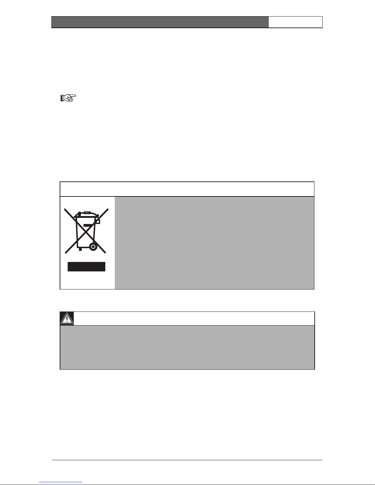
Only for EU countries
Do not dispose of electric tools together with household
waste material!
In observance of European Directive 2002/96/EC on waste
electrical and electronic equipment and its implementation in
accordance with national law, electric tools that have reached
the end of their life must be collected separately and returned
to an environmentally compatible recycling facility.
Caution
The power supply unit must comply with EN/UL 60950 or equivalent
safety standard. The power supply unit must be a SELV (Safety Extra Low
Voltage) source with single fault protection. IEEE802.3af compliant power
sources are SELV devices by default.

EN | x
Bosch Security Systems | 2006-05 | V2.0
Dinion IP | Installation Manual

EN | 11
Bosch Security Systems | 2006-05 | V2.0
Dinion IP | Installation Manual
Introduction 1
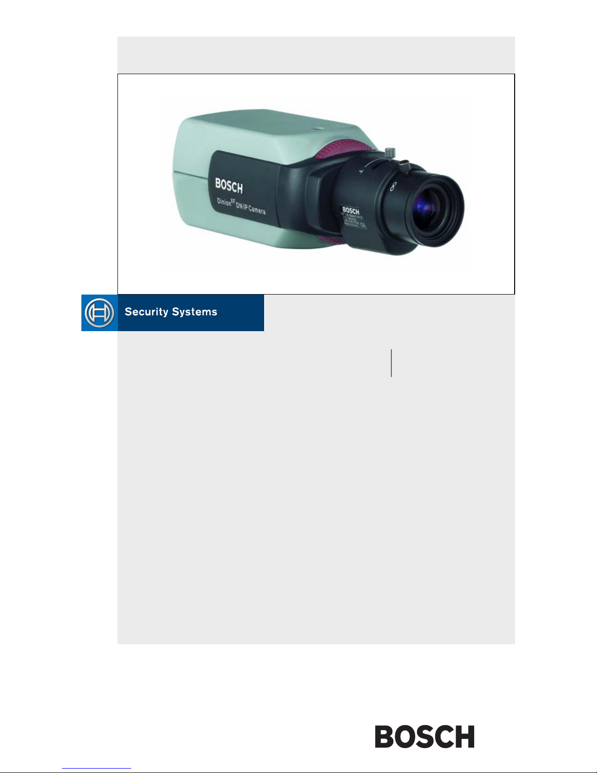
The Dinion IP camera is a high-performance smart surveillance color camera. It
incorporates advanced digital signal processing for outstanding picture
performance. The camera operates as a network video server and transmits video
and control signals over data networks such as Ethernet LANs and the Internet.
The Dinion IP camera is easy to install and ready to use, and offers the best
solution for demanding scene conditions. Features include:
• NightSense™ extends the low-light performance of the camera
• Enhanced video motion detection
• Video and data transmission over IP data networks
• Tri Streaming function for simultaneous encoding with three individually
definable profiles
• Multicast function for simultaneous picture transmission to multiple receivers
• One analog composite video output CVBS (PAL/NTSC)
• Video encoding using international MPEG-4 standard
• Integrated Ethernet interface (10/100 Base-T)
• Remote control of all built-in functions via TCP/IP
• Password protection to prevent unauthorized connection or configuration
changes
• Relay input for external sensor (such as door contacts)
• Event-driven, automatic connection (for example at switch-on and for alarms)
• Fast, convenient configuration using the integrated Web server and a browser
• Firmware update through flash memory
• Convenient upload and download of configuration data

EN | 12
Bosch Security Systems | 2006-05 | V2.0
Dinion IP | Installation Manual
Type number overview
Unpacking
Unpack carefully and handle the equipment with care. The packaging contains:
•Dinion
XF
IP camera
• CS to C lens mount adapter
• CCD protection cap
• Spare lens connector (male)
•CD ROM
– Quick Installation Guide
–Manual
– Configuration Manager
– MPEG ActiveX control
–MPEG viewer
– Adobe Acrobat Reader
• Quick install instructions
Note
If equipment appears to have been damaged during shipment, repack it in
the original packaging and notify the shipping agent or supplier.
System requirements
• Computer with Windows 2000/XP operating system, network access and
Microsoft Internet Explorer web browser version 6.0 or later
or
Typ e n um be r NWC-0455-10P NWC-0455-20P
Standard 50 Hz 60 Hz
Supply voltage 24 VAC or 12 VDC (use class 2 power supply) or
PoE (IEEE 802.3af)
CCD type 1/3"

EN | 13
Bosch Security Systems | 2006-05 | V2.0
Dinion IP | Installation Manual
• Computer with Windows 2000/XP operating system, network access and
reception software, for example VIDOS or DIBOS 8.0
or
• MPEG-4 compatible hardware decoder from Bosch Security Systems (such as
VIP XD) as a receiver and a connected video monitor
The minimum PC requirements are:
• Operating platform: A PC running Windows 2000 or Windows XP with IE6.0
• Processor: 1.8 GHz Pentium IV
• RAM memory: 256 MB
• Video system: 128 MB video memory, 1024x768 display with 24-bit color
• Network interface: 100-BaseT
• DirectX: 9.0b
Note
Make sure the graphics card is set to 16-bit or 32-bit color depth and that
Microsoft Virtual Machine or Java Virtual Machine is installed on your
PC. To play back live video images, an appropriate MPEG ActiveX must
be installed on the computer. If necessary, install the required software and
controls from the product CD provided. If you need further assistance,
contact your PC system administrator.
Overview of functions
The camera incorporates a network video server. Its primary function is to
encode video and control data for transmission over an IP network. With its
MPEG-4 encoding it is ideally suited for IP communication and for remote
access to digital video recorders and multiplexers. The use of existing networks
means that integration with CCTV systems or local networks can be achieved
quickly and easily. Video images from a single camera can be simultaneously
received on several receivers.

EN | 14
Bosch Security Systems | 2006-05 | V2.0
Dinion IP | Installation Manual
Wide dynamic range
The digital signal is automatically processed in the camera to optimally capture
the detail in both the high and low light areas of the scene simultaneously,
maximizing the information visible in the picture.
Power-over-Ethernet
Power for the camera can be supplied via a Power-over-Ethernet (IEEE 802.3af)
compliant network cable connection. With this configuration, only a single cable
connection is required to view, power and control the camera.
Receiver
MPEG-4 compatible hardware decoders (for example VIP XD) can be used as a
receiver. Computers with decoding software such as VIDOS or computers with
the Microsoft Internet Explorer web browser installed can also be used as
receivers.
Video encoding
The camera uses the MPEG-4 compression standard. Thanks to efficient
encoding, the data rate remains low even with high image quality and can also be
adapted to local conditions within wide limits.
Tri Streaming
Tri Streaming allows the incoming data stream to be encoded simultaneously
according to three different, individually customized profiles. This creates two
MPEG4 streams per camera that can serve different purposes, for example one
for local recording and one optimized for transmission over the LAN, and an
additional JPEG stream for use with a PDA for example.
Recording
The NWC-0495 can be used with an iSCSI server connected via the network to
store long-term recordings.
Multicast
In suitably configured networks, the multicast function enables simultaneous, real
time transmission to multiple receivers. The prerequisite for this is that the UDP
and IGMP V2 protocols are implemented on the network.

EN | 15
Bosch Security Systems | 2006-05 | V2.0
Dinion IP | Installation Manual
Configuration
The camera can be configured using a browser on the local network (Intranet) or
from the Internet. Similarly, firmware updates and rapid loading of device
configurations are also possible. Configuration settings can be stored as files on a
computer and copied from one camera to another.
Tampering recognition and motion detectors
The NWC-0495 offers a wide range of configuration options for alarm signaling
in the event of tampering with the camera. An algorithm for detecting movement
in the video image is also part of the scope of delivery and can optionally be
extended to include special video analysis algorithms.
Snapshots
Individual video frames (snapshots) can be called up as JPEG images, stored on
the hard drive or displayed in a separate browser window.
Backup
The browser application Livepage has an icon for saving the video images
provided by the unit as a file on your computer's hard drive. Clicking this icon
stores the video sequences and they can be replayed with the MPEG viewer from
Bosch Security Systems included with the package.
EN | 16
Bosch Security Systems | 2006-05 | V2.0
Dinion IP | Installation Manual
Connections 2
Power
Caution
Ensure that your power supply matches the rated voltage of your camera
before installing.
Caution
Never supply power via the power connector when power is supplied via
the Ethernet connection (PoE).
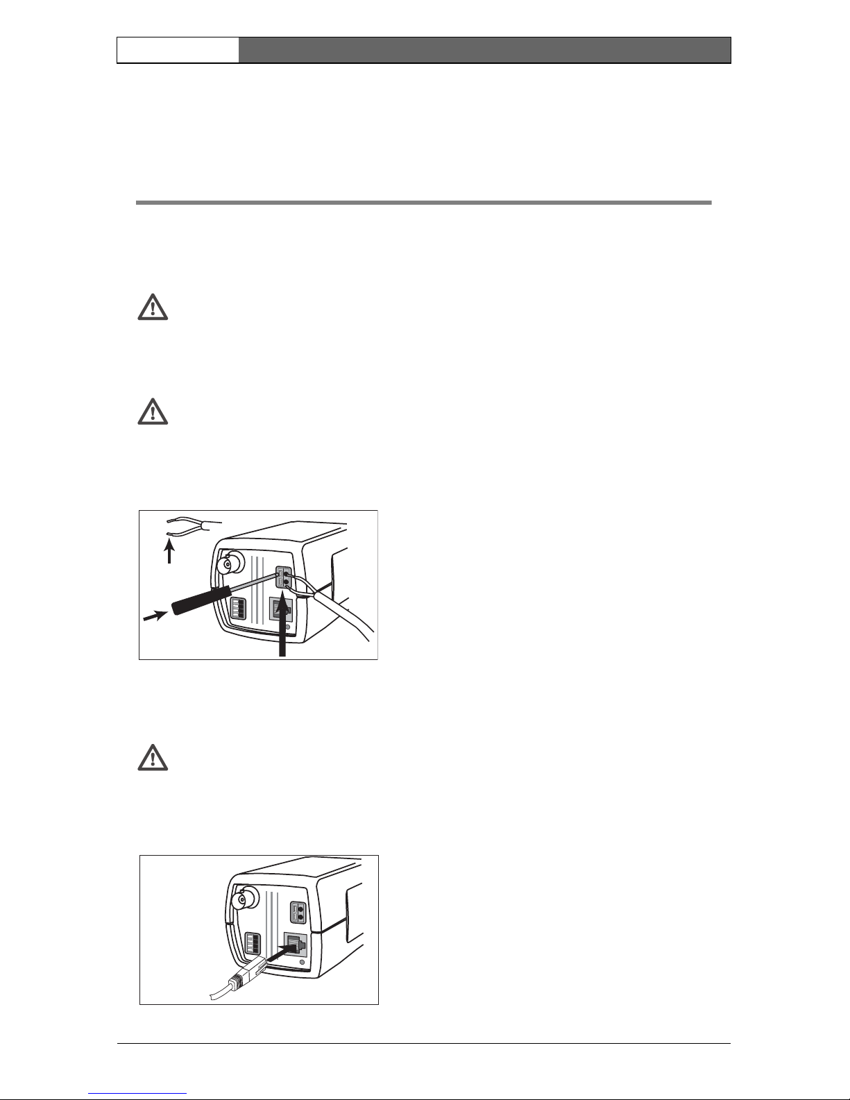
Network (and power)
Caution
Never supply power via the Ethernet connection (PoE) when power is
supplied via the power connector.
VIDEO
D
C
12V
AC
24V
ALARM
ETH
10mm
• use a class 2 power supply
• 24 VAC or 12 VDC
• push in the tabs to open the quick-connectors
(these connections are not polarity sensitive).
• use AWG16 to 22 stranded wire or AWG16 to
26 solid wire; cut back 10mm (0.4") of
insulation.
VIDEO
DC
1
2
V
AC
2
4
V
ALARM
ETH
UTP Cat 5 RJ45
• connect the camera to a 10/100 Base-T
network.
• use a shielded UTP Category 5 cable with
RJ45 connectors.
• Power can be supplied to the camera via the
Ethernet cable compliant with the Power-overEthernet (IEEE 802.3af) standard.
EN | 17
Bosch Security Systems | 2006-05 | V2.0
Dinion IP | Installation Manual
Note
The multicolored LED under the Ethernet connection indicates Power
(red), IP connection (green) and IP traffic (green flashing). It can be
disabled in the Settings/Camera Settings/Installer options
menu.
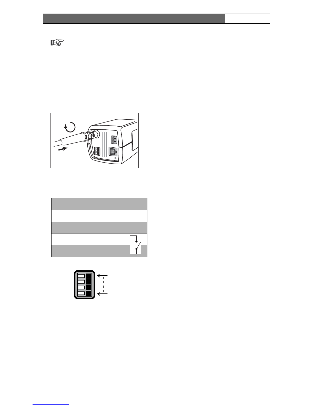
Video service monitor
Alarm connector
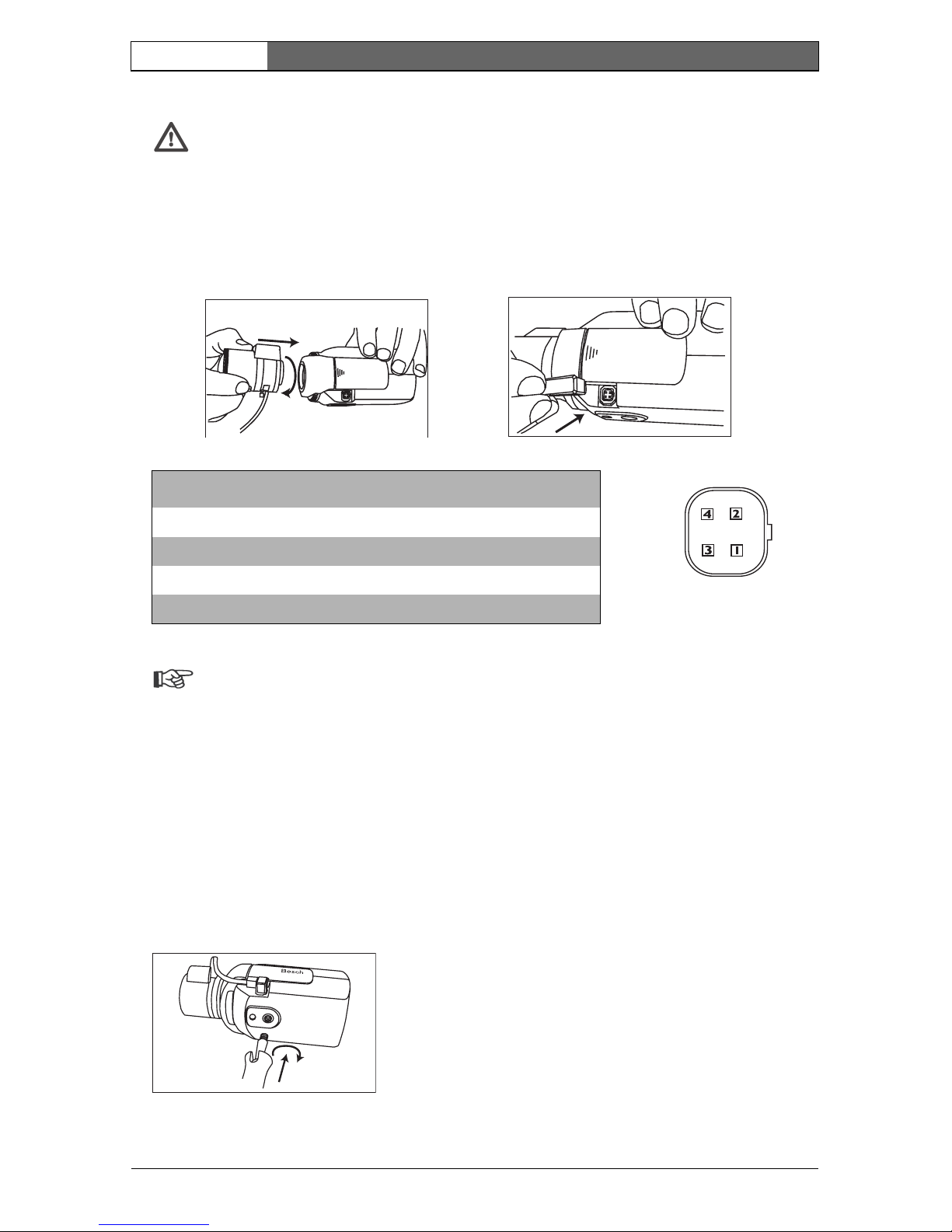
Lens mounting
The camera accepts CS-mount lenses with a lens protrusion of up to 5mm.
C-mount lenses can be mounted using the lens adapter ring. DC-iris lenses are
recommended for the best picture performance. The camera automatically
detects the type of lens used and optimizes performance accordingly. A spare
male lens connector is provided.
VIDEO
DC 12V
AC 24V
ALAR
M
ETH
• connect a service monitor to the composite
video BNC connector to aid installation.
• a monitor connected close to the camera via
this connection can also be used in parallel with
remote PC viewing.
Alarm
Pin 1
Pin 4
Pin Alarm socket
1Ground
2 Alarm in
3 Relay out contact 1
4 Relay out contact 2
• Max. wire diameter AWG 22-28
for both stranded and solid.
• Default relay position n.o. (normally
open), no alarm.
• Alarm output relay switching
capability: Max voltage 30VAC or
+40VDC. Max 0.5 A continuous,
10VA .
• Alarm in: TTL logic, +5V nominal,
+40VDC max, DC coupled with
22kOhm pull-up to +3.3V.
• Alarm in: configurable as active
low or active high.
• Max. 42V allowed between camera
ground and each of the relay pins.
EN | 18
Bosch Security Systems | 2006-05 | V2.0
Dinion IP | Installation Manual
Caution
To avoid damaging the CCD sensor when using a C-mount lens, make
sure the supplied lens adapter ring is mounted onto the camera before
mounting the lens.
Lenses weighing more than 0.5 kg (1.1lbs) must be separately supported.
Note
If a short circuit is detected on the lens connector, the on-screen display
(OSD) failure message LENS SHORT CIRCUIT is shown. The lens circuit
is automatically disabled to avoid internal damage. Remove the lens
connector and check the pin connections.
Mounting the camera
The camera can be mounted from the top or bottom. The bottom mounting is
isolated from ground. With outdoor scenes, a DC-iris lens is recommended.
Bosch
Bosch
Pin Video iris lens DC iris lens
1 Supply (11.5V ±0.5, 50mA max.) Damp -
2 Not used Damp +
3 Video signal 1Vpp 1kOhm Drive +
4 Ground Drive -

EN | 19
Bosch Security Systems | 2006-05 | V2.0
Dinion IP | Installation Manual
Caution
Do not point the camera/lens into direct sunlight.
Do not obstruct the free flow of air around the camera.
Note
The camera becomes quite warm when operating; this is normal.
However, you should take this into account when touching the camera.
EN | 20
Bosch Security Systems | 2006-05 | V2.0
Dinion IP | Installation Manual
Quick set-up 3
The Dinion IP camera normally provides an optimal picture without the need for
further adjustments. Configuration of the camera is carried out remotely via the
network using a web browser. However, the camera also has an Installer menu in
which basic installation settings (lens wizard, IP address) can be accessed. To
view this menu connect a monitor to the composite video output of the camera.
Back focus adjustment
To optimize picture sharpness in both bright and low-level lighting, adjust the
back focus. Use the camera's unique Lens Wizard. This ensures that the object of
interest always remains in focus even when focusing at the maximum lens
opening.
– When back focusing vari-focus lenses, adjust to obtain a sharp picture in both
wide-angle and tele positions for both far and near focus.
– When back focusing zoom lenses, ensure the object of interest remains in
focus throughout the entire zoom range of the lens.
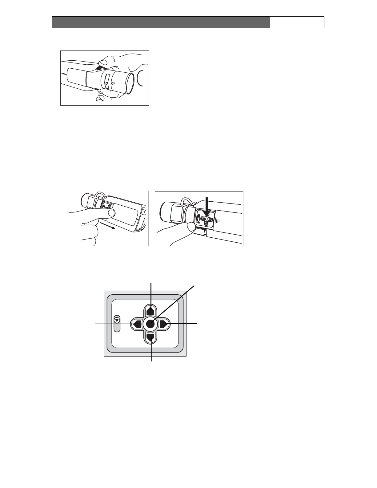
To adjust back focus:
1. Open the slide door at the side of the camera
2. Unlock the back focus locking button.
3. Turn the back focus adjustment as required.
Bosch
Bosch
EN | 21
Bosch Security Systems | 2006-05 | V2.0
Dinion IP | Installation Manual
4. Lock the back focus locking button.
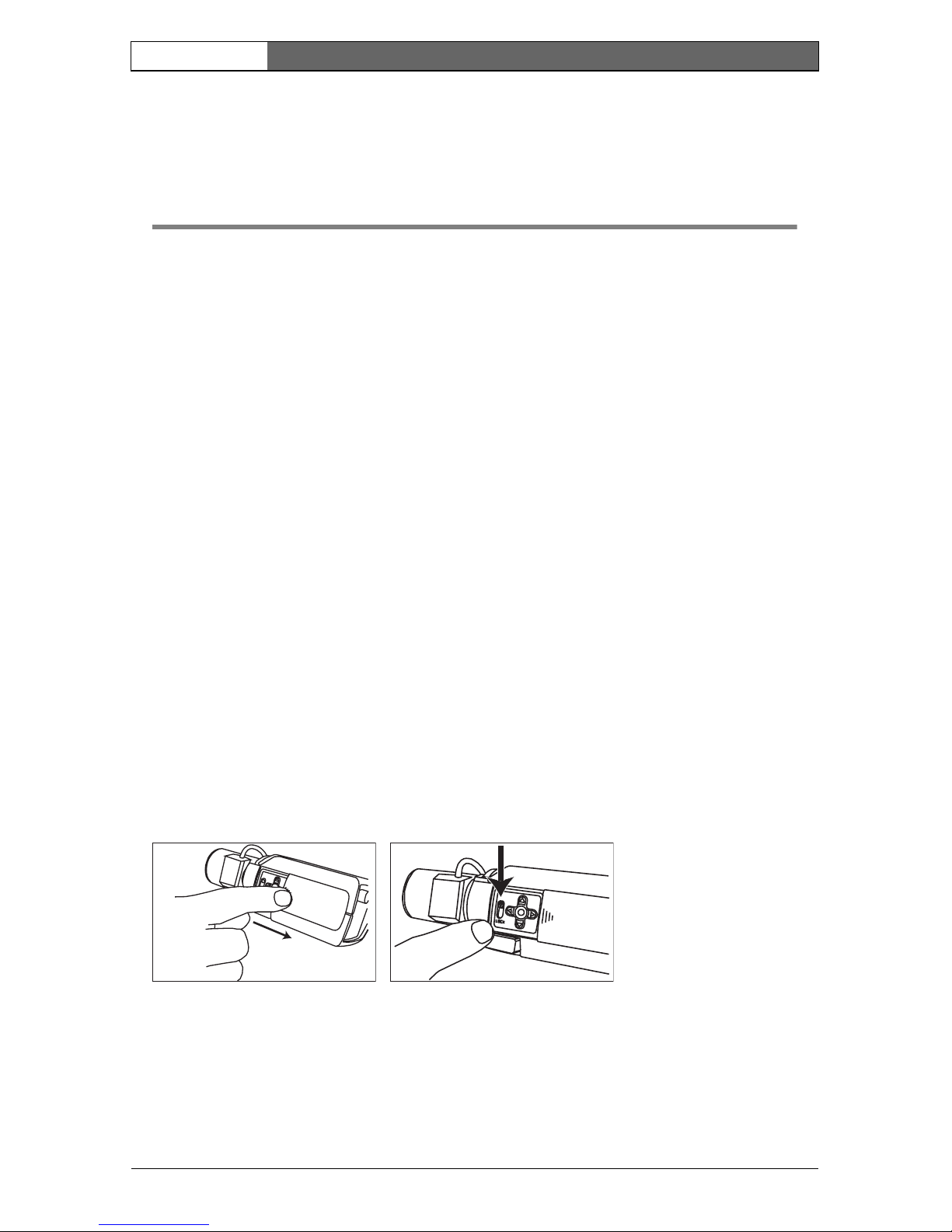
Accessing and navigating quick set-up menu
Five keys, located behind the side panel, are used for navigating through the
quick set-up menu. To access the set-up menus, press the menu/select key
(center). The main menu appears on the monitor.
How to use the navigation keys
• Press the menu/select key to access the menus or to move to the next or
previous menu.
• Press the menu/select key for approximately 1.5 seconds to open the Installer
menu.
• Use the up or down keys to scroll up or down through a menu.
Bosch
Bosch
Bosch
Lock
Menu/select
Right key
Down key
Up key
Left key

EN | 22
Bosch Security Systems | 2006-05 | V2.0
Dinion IP | Installation Manual
• Use the left or right keys to move through options or to set parameters.
• When in a menu, quickly pressing the menu/select key twice restores the
selected item to its factory default.
• To close all menus at once from any menu, select the Exit item and hold down
the menu/select key until the menu display disappears.
Install menu
Install lens wizard submenu
Adjustment procedure DC-iris Lens
1. Unlock the back focus locking button.
2. Access the Lens Wizard menu.
3. Set Back Focus Now is highlighted in the menu.
4. Turn the back focus adjustment as required.
5. Lock the back focus locking button.
6. Exit the menu.
Function Selection Description
Lens Wizard Select submenu Select to optimize camera lens combination
Network Select submenu Select to set the network IP address for the camera
(d efa ul t ad dre ss i s 19 2.168. 0.1)
Exit Exit the menu
Function Selection Description
Lens Type AUTO, MANUAL,
DCIRIS, VIDEO
In AUTO mode the camera auto detects the type of
lens used or force the camera into a mode.
Detected If the LENS TYPE detection is in AUTO, the
detected lens type is shown.
Set Back
Focus Now
Select to force lens to its maximum opening. After
focusing the lens the object of interest remains in
focus in bright and low light conditions.
Set LVL (Video iris lenses only). The level detector indicator
must be set to the center by adjusting the level
potentiometer on the lens, to obtain the best picture
performance.
Exit Return to the INSTALL menu

EN | 23
Bosch Security Systems | 2006-05 | V2.0
Dinion IP | Installation Manual
Adjustment procedure Manual-iris Lens
1. Unlock the back focus locking button.
2. Adjust the lens to the maximum lens opening.
3. Turn the back focus adjustment as required.
4. Lock the back focus locking button.
Adjustment procedure Video-iris Lens
1. Unlock the back focus locking button.
2. Access the Lens Wizard menu.
3. Set Back Focus Now is highlighted in the menu.
4. Turn the back focus adjustment as required.
5. Lock the back focus locking button.
6. Select Set LVL in the menu; the Level bar appears.
7. Point the camera at the scene it will be mostly viewing.
8. Adjust the level potentiometer located on the lens until the Level bar is in
the central position.
9. Exit the menu.
Note
The best performance with video iris lenses is obtained when the peak/
average potentiometer of the lens matches the peak/average balance
configuration setting.
Install IP address submenu
To operate the camera in your network, a network-valid IP address must be
assigned. The factory default IP address is 192.168.0.1
Function Selection Description
IP Address Enter an IP address for the camera. Use LEFT/
RIGHT to change position in the address, use UP/
DOWN to select the digit. Use SELECT to exit the
address edit screen.
Subnet Mask Enter the Subnet mask (default 255.255.255.0)
Gateway Enter a Gateway address.
Exit Return to the Install menu

EN | 24
Bosch Security Systems | 2006-05 | V2.0
Dinion IP | Installation Manual
Note
The new IP address, subnet mask and gateway address are set after you
leave the menu. The camera reboots internally and the new values are set
after a few seconds.
Defaults
To restore all parameters (including IP address) to the factory defaults, press and
hold the Up navigation key for at least 10 seconds and then confirm. Allow a few
seconds for the camera to optimize the picture after a mode reset.
Note
Restoring the factory defaults may result in the loss of the IP connection.
If this occurs, change the IP address of your browser to the factory default
value. Only restore the factory defaults when it is absolutely necessary.

EN | 25
Bosch Security Systems | 2006-05 | V2.0
Dinion IP | Installation Manual
Network connection 4
A computer with Microsoft Internet Explorer can be used to receive live images
from the camera, control cameras and replay sequences stored on the local hard
drive. The camera is configured over the network using the browser or via the
Configuration Manager (supplied with the product). The configuration options
using the menu system of the camera itself are limited to setting up the lens and
network.
Note
The camera can also be connected to DIBOS 8.0, VIDOS and BVMS
video management systems as well as third party video management
systems.
System requirements (see page 12 for more detailed requirements)
• Microsoft Internet Explorer version 6.0 or higher
• Monitor resolution 1024 × 768 pixels
• Intranet or Internet network access
To play back live video images, an appropriate MPEG ActiveX must be installed
on the computer. If necessary, the required software and controls can be installed
from the product CD provided.
– Insert the CD into the CD-ROM drive of the computer. If the CD does not
start automatically, open the root directory of the CD in Windows Explorer
and double click MPEGAx.exe.
– Follow the on-screen instructions.
Establishing the connection
The camera must be assigned a valid IP address to operate on your network. The
default address pre-set at the factory is 192.168.0.1
– Start the Web browser.
– Enter the IP address of the camera as the URL.
EN | 26
Bosch Security Systems | 2006-05 | V2.0
Dinion IP | Installation Manual
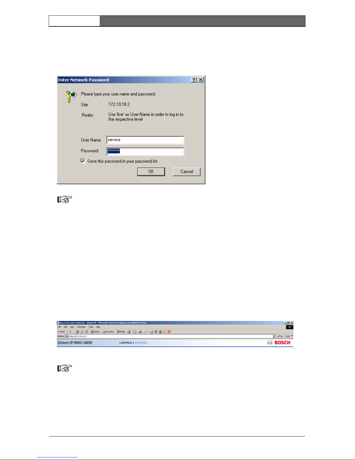
Password protection in camera
If the camera is password-protected, a message to enter the password appears.
Note
A camera offers you the option of limiting access across various
authorization levels.
– Enter the user name and the associated password in the appropriate fields.
– Click OK. If the password is correct, the desired page is displayed.
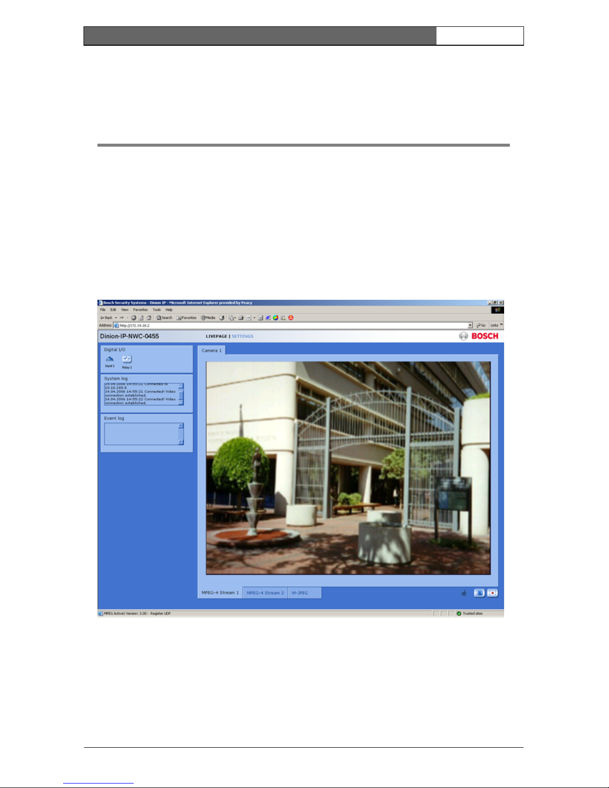
After a short time when the connection is established, the Livepage with the
video image appears. In the application title bar the Livepage selection is used to
operate the camera; the Settings selection is used to configure the camera and
the application interface.
Note
If the connection is not established, the maximum number of possible
connections may already have been reached. The maximum number of
connections depends on the device and network configuration.
EN | 27
Bosch Security Systems | 2006-05 | V2.0
Dinion IP | Installation Manual
Operation via the browser 5
Livepage
After the connection is established, the Livepage is initially displayed. It shows
the live video image on the right of the browser window. Depending on the
configuration, various text overlays may be visible on the live video image. Other
information may also be shown next to the live video image on the Livepage.
The display depends on the settings on the Livepage configuration page.
Image selection
You can view the image on a full screen.
– Click on one of the MPEG-4 Stream 1, MPEG-4 Stream 2 or M-JPEG tabs
below the video image to switch between the different displays for the camera
image.
EN | 28
Bosch Security Systems | 2006-05 | V2.0
Dinion IP | Installation Manual
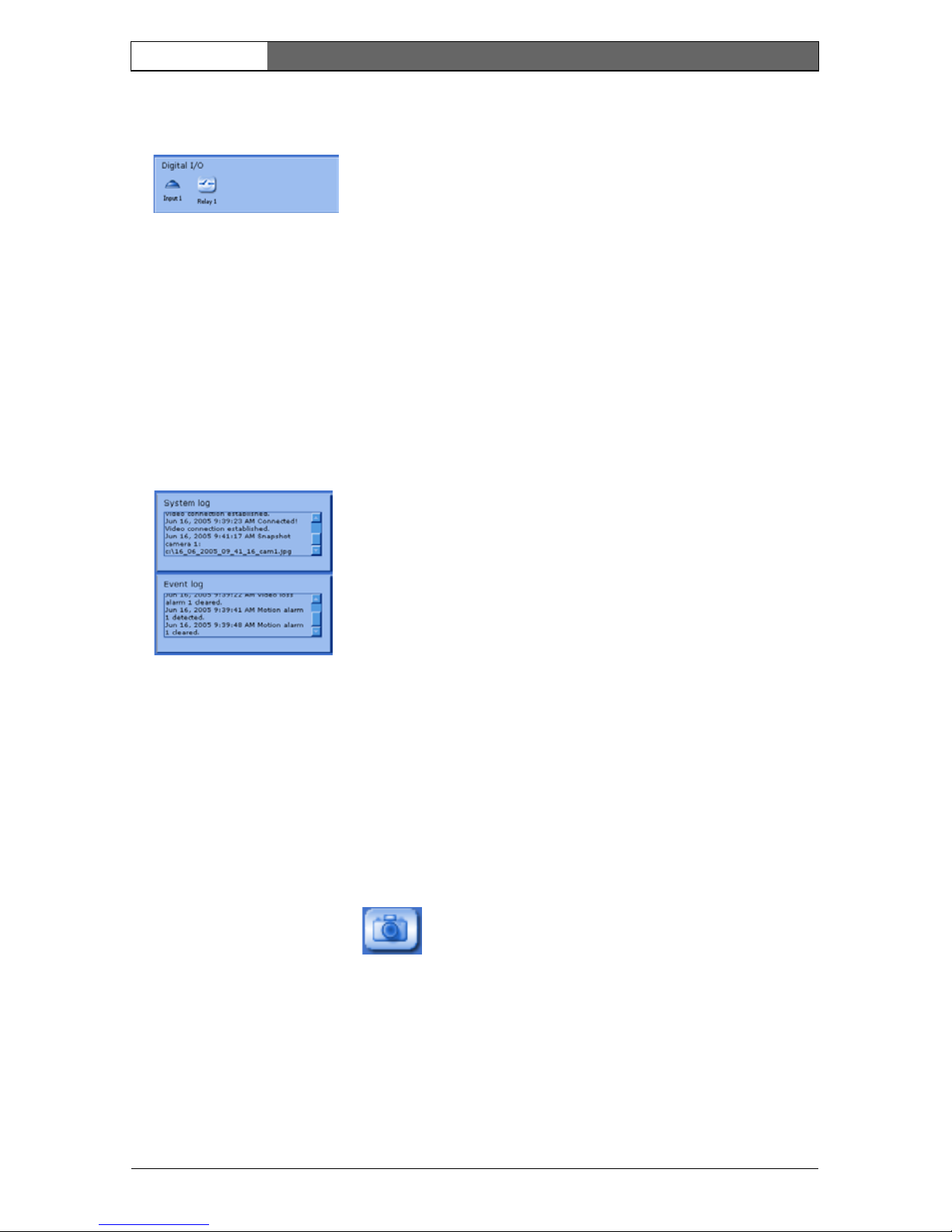
Digital I/O
Depending on the configuration of the unit, the alarm input and the relay output
are displayed next to the camera image. The alarm symbol is for information and
indicates the input status of the alarm input: Active 1 = Symbol is green, Active 0
= Symbol not lit. The relay on the camera allows you to operate a device (for
example a light or a door opener).
– To operate, click the relay symbol next to the video image. The symbol is red
when the relay is activated.
System log / Event log
The System log field contains information about the operating status of the
camera and the connection. These messages can be saved automatically in a file.
Events such as the triggering or end of alarms are shown in the Event log field.
These messages can be saved automatically in a file.
Saving snapshots
Individual images from the video sequence that is currently being shown on the
Livepage can be saved in JPEG format on the computer's hard drive.
– Click the camera icon to save single images.
– The image is saved at a resolution of 704 × 576/480 pixels (4CIF). The
storage location depends on the configuration of the camera.
Recording video sequences
Sections of the video sequence that is currently being shown on the Livepage can
be saved on the computer's hard drive. The sequences are recorded at the

EN | 29
Bosch Security Systems | 2006-05 | V2.0
Dinion IP | Installation Manual
resolution specified in the encoder configuration. The storage location depends
on the configuration of the camera.
– Click the recording icon to record video sequences.
– Saving begins immediately. The red dot on the icon flashes to indicate that a
recording is in progress.
– Click the symbol for recording video sequences again. Saving is terminated.
Installing MPEG viewer
You can play back saved video sequences using the MPEG viewer from
Bosch Security Systems, which can be found on the software CD supplied.
Note
A corresponding MPEG ActiveX (located on the CD provided with the
product) must be installed on the computer in order to play back saved
video sequences using the MPEG viewer.
– Insert the CD into the CD-ROM drive of the computer. If the CD does not
start automatically, open the CD in the Windows Explorer.
– Open the MPEG Viewer directory and copy the file MPEGViewer.exe to
your computer's hard drive.
– If necessary, you can also start the MPEG viewer by double-clicking the file
MPEGViewer.exe.
Running recording program
The hard drive icon below the camera images on the Livepage changes during an
automatic recording to the RAM memory of a NWC-0495 or to an iSCSI storage
device.
The icon lights up and displays a moving graphic to indicate a running
recording. If no recording is taking place, a gray icon is displayed.
Recordings page
You can access the Recordings page for playing back recorded video sequences
from the Livepage as well as from the Settings menu.
 Loading...