

Bosch DB18C3100R2, DiBos, DiBos Micro Installation Manual

DiBos/DiBos Micro
en Installation Guide


DiBos/DiBos Micro Table of Contents | en 3
Bosch Sicherheitssysteme GmbH Installation Guide F.01U.033.308 | V7 | 2009.09
Table of Contents
1Safety Notes 7
2Introduction 11
2.1 System Description 11
2.2 Unpacking 11
2.3 Power 11
2.4 Environmental 11
2.5 Recommended Virus Scanners/Firewall 12
2.5.1 Virus Scanners 12
2.5.2 Firewall 12
2.6 System Overview/Technical Specifications 14
2.6.1 DiBos 14
2.6.2 DiBos micro 18
3 Device Connections 21
3.1 DiBos 21
3.1.1 DiBos Front View 21
3.1.2 DiBos Rear View 22
3.1.3 Grabber Card for DiBos 23
3.1.4 I/O Card for DiBos 24
3.2 DiBos micro 25
3.2.1 DiBos micro Front View 25
3.2.2 DiBos micro Rear View 26
3.2.3 Grabber Card for DiBos micro 27
3.2.4 I/O Card (for DiBos micro) 28
4 Quick Installation 30
5 Quick Configuration 31
5.1 General Settings 31
5.2 Creating a User 33
5.3 Setting up the Network 34
5.4 Specifying Cameras 36
5.5 Assigning Time Profiles 37
5.6 Setting Up Recording 38
6 Default Configuration 40
6.1 Configuring Drives 40
6.2 Configuring Video and Audio Connections 42
6.2.1 General Camera Settings 44
6.2.2 Setting up Dome Cameras and Pan/Tilt Cameras 46
6.2.3 Specifying Monitoring Zone for Motion Cameras 49
6.2.4 Configuring Tamper Detection 50
6.2.5 Configuring Video Monitors 52
6.2.6 Configuring camera sequence 53

4 en | Table of Contents DiBos/DiBos Micro
F.01U.033.308 | V7 | 2009.09 Installation Guide Bosch Sicherheitssysteme GmbH
6.2.7 Editing Audio Settings 54
6.2.8 Configuring JPEG IP Cameras 55
6.2.9 Configuring MPEG4 IP Cameras 58
6.3 Configuring Recording Settings 60
6.3.1 Configuring Recording Settings for Analog Cameras 60
6.3.2 Configuring Recording Settings of JPEG IP Cameras 67
6.3.3 Configuring Recording Settings of MPEG4 IP Cameras 69
6.4 Configuring Time Periods 71
6.5 Configuring Inputs and Outputs 73
6.5.1 Configuring Alarm Inputs 73
6.5.2 Configuring Relay Outputs 74
6.5.3 Configuring Alarm Simulation 75
6.5.4 Configuring Virtual Inputs 76
6.5.5 Configuring Automatic Teller Machines 77
6.5.6 Configuring Foyer Card Readers 79
6.5.7 Configuring AP Inputs 82
6.5.8 Configuring POS Inputs 86
6.5.9 Configuring ATM/POS Inputs 88
6.6 Configuring Alarm Processing 90
6.7 Configuring Remote Stations 94
6.8 Configuring Alarm Transmission 97
6.9 Configuring the Export Video Scheduler 100
6.10 Creating Authorization Levels 102
6.11 Configuring Users 107
6.12 Configuring Error Forwarding 109
6.13 Configuring Options 111
6.13.1 MIB List for SNMP 114
6.13.2 Notification via SNMP 115
6.13.3 Configuring Automatic Alarm Recording 116
6.14 Configuring Browser Access and Network Settings 117
6.15 Administration and Dongle 119
6.15.1 Activating a License 122
7 Remote configuration 123
8XP Administration 124
8.1 Logging On as a Windows® XP User 124
8.2 Logging On as a Windows® XP Administrator 124
8.3 Changing the Administrator Password 124
9 Connections 125
9.1 Network Connection via DSL 125
9.2 Connecting the ISDN Controller 128
9.3 Connecting VSCom 200 H (Interface Expansion) 129
9.4 Connecting External Hard Disks 129
9.5 Connecting a Malfunction Relay 129
9.6 Connecting an ATM (Serial) 130
9.7 Connecting the MINITER RS 485 Foyer Card Reader 134
9.8 Connecting the DCF 77 Radio Clock 137

DiBos/DiBos Micro Table of Contents | en 5
Bosch Sicherheitssysteme GmbH Installation Guide F.01U.033.308 | V7 | 2009.09
9.9 Connecting a Modem/ISDN Card (for Incoming Connections) 139
9.10 Connecting to AutoDome/SAE Dome 141
9.10.1 Connecting to Bosch Dome Cameras (Directly) 141
9.10.2 Connecting to Bosch Dome Cameras via Matrix Switch 141
9.10.3 Connecting to SAE Dome Cameras (Directly) 142
9.10.4 Connecting to SAE Dome Cameras with V3032 Biphase Interface 142
9.11 Connecting an AP 143
9.11.1 General 143
9.11.2 Connecting to NZ 500 (20 mA) Video System NZ 500 145
9.11.3 Connecting to BZ 500 (20 mA) 145
9.11.4 Connecting to AZ 1010/NZ 1008 146
9.11.5 Connecting to NZ 1012 147
9.11.6 Connecting to NZ 1060 148
9.11.7 Connecting to UEZ 1000 (20 mA) 149
9.11.8 Connecting to UEZ 2000 (20 mA) 149
9.11.9 Connecting to UGM 2020 150
10 Troubleshooting and Checks 151
10.1 Troubleshooting 151
10.2 Checking the Optional Network Connection 152
10.3 Checking the Optional ATM Connection 153
10.4 Checking the Optional Web Connection 154
11 Notes on Service and Maintenance 155
11.1 Maintenance Work to be Carried Out 155
11.2 Software Update 156
11.3 Troubleshooting 156

6 en | Table of Contents DiBos/DiBos Micro
F.01U.033.308 | V7 | 2009.09 Installation Guide Bosch Sicherheitssysteme GmbH

DiBos/DiBos Micro Safety Notes | en 7
Bosch Sicherheitssysteme GmbH Installation Guide F.01U.033.308 | V7 | 2009.09
1Safety Notes
The following safety notes must be observed:
1. Read, follow and retain instructions
All safety and operating instructions must be read and followed before installing the
device. Retain instructions for future reference.
2. Observe warnings
Observe all warnings on the device and in the operating manual.
3. Add-on devices
Do not use add-on devices that are not recommended by the product manufacturer as
these may cause hazards.
4. Installation notes
Do not place the device on an unstable mounting, tripod or similar. The device may fall to
the ground and seriously injure the user or be damaged itself. Only use accessories that
have been recommended by the manufacturer or are delivered with the device. Fit the
device according to the manufacturer's instructions. Exercise extreme caution when
transporting the device on a trolley. Abrupt stopping, extreme force effects and uneven
surfaces may cause the device and the trolley to tip over.
5. Cleaning
Unplug the device from the mains power supply before cleaning. Follow all instructions
for the device. Normally, cleaning can be carried out with a damp cloth. Do not use liquid
cleaners or cleaners in spray cans.
6. Service
Do not attempt to service the device yourself. You may be exposed to high electrical
voltages or other hazards if you open or remove covers. Servicing must be carried out by
qualified maintenance personnel.
7. Damage requiring service.
Unplug the device from the mains power supply and arrange for the device to be serviced
by qualified personnel if:
– The mains cable or mains plug is damaged.
– Liquids or foreign bodies are present in the device.
– The device has come into contact with water and/or has been exposed to extreme
environmental conditions (e.g. rain, snow etc.).
– If the device does not work properly in spite of following the operating instructions,
make changes only to those operating elements that are described in the operating
instructions. Incorrect changes to other operating elements may cause damage
requiring extensive repair work to be carried out by qualified service personnel.
– The device has fallen to the ground or the housing has been damaged.
– A noticeable change in the performance of the device has occurred. In this case, the
device must be serviced.
8. Spare parts
If spare parts are required, service personnel must use spare parts that are
recommended by the manufacturer or correspond to the original parts. Using the wrong
spare parts may result in fire, electric shock or other hazards.
9. Safety test
When servicing or repair is complete, ask service personnel to carry out a safety test to
ensure that the device is working correctly.

8 en | Safety Notes DiBos/DiBos Micro
F.01U.033.308 | V7 | 2009.09 Installation Guide Bosch Sicherheitssysteme GmbH
10. Power source
The device must only be operated with the power source indicated on the label. If you are
not sure whether you can operate the device with a specific power source, ask the dealer
from whom you bought the device or your electricity provider.
You will find more information on devices that can be operated with batteries in the
operating manual.
For devices that are operated using external power units, only recommended and tested
power units should be used.
For devices that are operated using power units with limited power, the power unit must
conform to the EN 60950 standard. Other replacement power units may damage the
device and lead to fire or electric shock.
For devices that are operated using 24 V AC, the normal input voltage is 24 V AC. The
input voltage to the device should not exceed 30 V AC. The wiring provided by the
customer for connecting the power source to the device (24 V AC) must conform to
electrical codes (Class 2 power stages). The power source (24 V AC) must not be
grounded at the connectors or the power supply connections on the device.
11. Coax grounding
If a cable system is connected to the device for outside use, ensure that the cable system
is grounded. Only for models available in the USA: Section 810 of the National Electrical
Code, ANSI/ NFPA No.70-1981, contains information on the correct grounding of the
mounting, coax grounding at a discharge device, the size of the ground conductors, the
location of the discharge device, connection to discharge electrodes and requirements
regarding the discharge electrodes.
12. Grounding or polarizing
This device may have a polarized AC plug (a plug with one pin broader than the other).
With this protection system, the plug can only be inserted into a socket in one way. If you
are unable to insert the plug fully into the socket, rotate it and try again. If you are still
unable to insert the plug, ask an electrician to replace the socket with a later model. Do
not attempt to bypass the polarized plug.
Alternatively, the device may have a 3-phase ground plug with a third (grounding) pin.
With this protection system, the plug can only be inserted into a grounded socket. If you
are unable to insert the plug into the socket, ask an electrician to replace the socket with
a later model. Do not attempt to bypass the grounded plug.
13. Lightning
For added protection of the device during a storm, or when it is not used for a lengthy
period of time, unplug the device from the mains and disconnect the cable system. This
prevents the device being damaged by lightning or a power surge.
14. The installation location should be quiet and have only limited access.
DiBos/DiBos Micro Safety Notes | en 9
Bosch Sicherheitssysteme GmbH Installation Guide F.01U.033.308 | V7 | 2009.09
Devices for inside use
Water and damp — Do not use this device in the vicinity of water (e.g. in a damp cellar) or in
humid locations.
Entry of foreign bodies and liquids — Do not insert foreign bodies into the device openings
as you may touch parts that are at high-voltage or cause a short circuit, which may result in
fire or electric shock. Do not spill liquids on the device.
Mains cable and mains cable protectors — For devices that operate at 230 V AC, 50 Hz, the
input and output mains cables must conform to IEC publication 227 or IEC publication 245.
Mains cables should be laid in such a way that no one can step on them and no other objects
can be placed on top of them or leant against them. Particularly protect cables, plugs and
sockets as well as device entry points.
Overloading — Do not overload sockets and extension cables as this may result in fire or
electric shock.
Rack-mounting devices
Ventilation — This device should not be installed anywhere where correct ventilation cannot
be ensured or the manufacturer's instructions cannot be followed. The maximum operating
temperature for this device must not be exceeded.
Mechanical load — When installing the device in a rack, beware of hazards that may arise due
to unequal mechanical load.
WARNING!
Interruption of mains supply:
Voltage is applied as soon as the mains plug is inserted into the mains socket.
However, for devices with a mains switch, the device is only ready for operation when the
mains switch (ON/OFF) is in the ON position. When the mains plug is pulled out of the socket,
the supply of power to the device is completely interrupted.
WARNING!
Removing the housing:
To avoid electric shock, the housing must only be removed by qualified service personnel.
Before removing the housing, the plug must always be removed from the mains socket and
remain disconnected while the housing is removed. Servicing must only be carried out by
qualified service personnel. The user must not carry out any repairs.
WARNING!
Lithium battery:
Batteries that have been inserted wrongly can cause an explosion. Always replace empty
batteries with batteries of the same type or a similar type recommended by the manufacturer.
Dispose of empty batteries according to the manufacturer's instructions.
CAUTION!
Electrostatically sensitive device:
To avoid electrostatic discharges, the CMOS/MOSFET protection measures must be carried
out correctly.
When handling electrostatically sensitive printed circuits, grounded anti-static wrist bands
must be worn and the ESD safety precautions observed.

10 en | Safety Notes DiBos/DiBos Micro
F.01U.033.308 | V7 | 2009.09 Installation Guide Bosch Sicherheitssysteme GmbH
NOTICE!
Installation should only be carried out by qualified customer service personnel in accordance
with the applicable electrical regulations.
Disposal
Your Bosch product has been developed and manufactured using high-quality materials and
components that can be reused.
This symbol means that electronic and electrical devices that have reached the end of their
working life must be disposed of separately from household waste.
In the EU, separate collecting systems are already in place for used electrical and electronic
products. Please dispose of these devices at your local communal waste collection point or at
a recycling center.

DiBos/DiBos Micro Introduction | en 11
Bosch Sicherheitssysteme GmbH Installation Guide F.01U.033.308 | V7 | 2009.09
2 Introduction
2.1 System Description
The video system is a digital monitoring system that allows video images to be stored locally
and transmitted and evaluated at any place determined by you independently of distance and
location. The image data delivered by the video system provides additional information on the
magnitude of the danger and the developments before and after the event.
2.2 Unpacking
Check the packaging for visible damage. If anything is damaged during transport, please
inform the freight agency.
Unpack the device carefully. This is an electronic device and it must be handled carefully to
avoid damage. Do not attempt to put the unit into operation if components are damaged. If
parts are missing, inform your customer service representative or a Bosch Security Systems
salesperson.
The shipping box is the safest transport container for the device. Retain the box and the
packaging material for future use. If the device has to be returned, use the original packaging.
2.3 Power
Ensure that the power supply at the chosen location is stable and is within the values
specified for the device.
As this is an electronic device, the video system is sensitive to sudden voltage peaks, dropoff
and dropout.
To avoid damage to the electronic components and/or loss of data and ensure trouble-free
operation, we recommend installing an uninterruptible power supply (UPS).
Depending on the stability of the mains network, the following uninterruptible power supplies
are recommended:
– Mains networks with voltage peaks and voltage dropout:
Use of an offline UPS is sufficient (e.g. Pulsar ellipse 1000 for DiBos and Pulsar ellipse
600 for DiBos Micro).
– Mains networks with voltage peaks, voltage dropout and voltage dropoff:
Use of an online UPS is recommended.
For 1 video system, a UPS with at least 300 VA is required. If add-on devices (e.g. monitors,
sub-systems) are also to be protected, the capacity of the UPS must be raised accordingly.
2.4 Environmental
When choosing an installation location for the device, take the ambient temperature and
humidity into account.
12 en | Introduction DiBos/DiBos Micro
F.01U.033.308 | V7 | 2009.09 Installation Guide Bosch Sicherheitssysteme GmbH
2.5 Recommended Virus Scanners/Firewall
The DiBos operating system is Windows® XP Embedded.
DiBos is not supplied with a virus scanner or firewall. It is therefore the customer's
responsibility to purchase, install and update a virus scanner and firewall.
2.5.1 Virus Scanners
The following virus scanners are released. The virus scanners are listed in order of suitability.
1. Norton AntiVirus 2008
The software includes a firewall.
2. Trend Micro AntiVirus 2008
The software does not include a firewall; this must be purchased separately.
3. McAfee VirusScan 2008
The software includes a firewall.
2.5.2 Firewall
On DiBos with Windows XP Embedded and Service Pack 2 (SP2), the Windows firewall is
deactivated by default. The Windows firewall can be activated as required.
If the firewall is activated, you must add and select the following exceptions in the firewall
settings:
NOTICE!
We recommend that you install a virus scanner and firewall to protect against computer
viruses, computer worms and Trojans.
NOTICE!
– The virus scanner can affect the performance of the system.
– The real-time virus scanner must be activated to ensure sufficient protection against
viruses.
– If possible, all partitions on the hard disk that contain saved images should be excluded
from the scanning process.
– If possible, the C drive should be scanned at scheduled times. We recommend you carry
out a scan on a weekly basis. When the C drive is scanned, the performance of the system
falls significantly, along with the image refresh and storage rates.
Individual images may be lost.
– Removable drives, e. g. USB memory sticks, USB drives, CD/DVD drives and diskette
drives, must be manually checked when inserted to ensure sufficient protection.
– Always use the most up-to-date virus scanner.
Firewall settings DiBos 8
Exceptions ConnectionServer.exe
DVR ServiceShimWrapper.exe
DBServer.exe
DCOM (TCP) Port 135
DCOM (UDP) Port 135
DiBosExplorer.exe
DomeCameraUnit.exe
JobServer.exe
VCSModule.exe

DiBos/DiBos Micro Introduction | en 13
Bosch Sicherheitssysteme GmbH Installation Guide F.01U.033.308 | V7 | 2009.09
The DiBos processes must also be activated in the firewall of the virus scanner software.
The necessary ports to disable the firewall can be set in the configuration (see also
Section 6.14 Configuring Browser Access and Network Settings).
NOTICE!
Always use the newest version of the firewall.

14 en | Introduction DiBos/DiBos Micro
F.01U.033.308 | V7 | 2009.09 Installation Guide Bosch Sicherheitssysteme GmbH
2.6 System Overview/Technical Specifications
2.6.1 DiBos
Electrical data
Compression technique MPEG4
Camera inputs (analog) 6 BNC connections (DB 06 C1), 12 BNC connections (DB
12 C2), 18 BNC connections (DB 18 C3), 24 BNC
connections (DB 24 C4), 30 BNC connections (DB 30 C5)
Camera inputs (IP) 16 video/audio MPEG4 data streams from Bosch/VCS
network devices or JPEG devices (DB 06 C1, DB 12 C2, DB
18 C3)
32 video/audio MPEG4 data streams from Bosch/VCS
network devices or JPEG devices (DB 24 C4, DB 30 C5)
Composite video signal 1 Vpp +/-3 dB (min. 0.7 Vpp, max. 1.4 Vpp), 75 Ohm
Video looping out Via connecting cable
Recording resolution (analog
inputs)
PAL:
704 x 576 (4CIF), 704 x 288 pixels (2CIF), 352 x 288 pixels
(CIF)
NTSC:
704 x 480 (4CIF), 704 x 240 pixels (2CIF), 352 x 240 pixels
(CIF)
Recording resolution (IP
inputs/Bosch IP devices)
PAL:
704 x 576 (4CIF/D1), 704 x 288 (2CIF), 464 x 576 (2/3
D1), 352 x 576 (1/2 D1), 352 x 288 (CIF), 176 x 144 (QCIF)
NTSC:
704 x 480 (4CIF/D1), 704 x 240 (2CIF), 464 x 480 (2/3
D1), 352 x 480 (1/2 D1), 352 x 240 (CIF), 176 x 120 (QCIF)
Recording rate (analog) for
DiBos models
IPS CIF
(PAL)
IPS CIF
(NTSC)
IPS 2CIF
(PAL)
IPS 2CIF
(NTSC)
IPS 4CIF
PAL
IPS 4CIF
NTSC
DB 06 C1 xxx R2 75 90 50 60 25 30
DB 12 C2 xxx R2 150 180 100 120 50 60
DB 18 C3 xxx R2 225 270 150 180 75 90
DB 24 C4 xxx R2 300 360 200 240 100 120
DB 30 C5 xxx R2 375 450 250 300 125 150
Recording rate per channel
(analog video inputs)
PAL:
0.5; 1; 2; 3; 4; 5; 6; 8; 12.5; 25 images per second
NTSC:
0.5; 1; 2; 3; 5; 6; 7.5; 10; 15; 30 images per second
Image size (analog video
inputs)
Configurable from approx. 1.5 kB to 30 kB (depending on
the changes in the image)
Maximum recording rate
(analog and IP)
50 Mbit per second

DiBos/DiBos Micro Introduction | en 15
Bosch Sicherheitssysteme GmbH Installation Guide F.01U.033.308 | V7 | 2009.09
Recording rate per channel
(IP video inputs)
PAL:
0.5; 1; 2; 3; 4; 5; 6; 8; 12.5; 25 images per second
NTSC:
0.5; 1; 2; 3; 5; 6; 7.5; 10; 15; 30 images per second
Image size (IP video inputs) Configurable up to 3 Mbit per camera
Supported single-channel
encoder (Bosch VideoJet
series and Bosch VIP series)
VideoJet 10S, VideoJet 1000
VideoJet X10
VIP X1, VIP 10
Supported multi-channel
encoder (Bosch VideoJet
series and Bosch VIP series)
VideoJet 8004, VideoJet 8004A,
VideoJet 8008, VideoJet 8008A,
VideoJet X20, VideoJet X40,
VIP X2, VIP X2A, VIP X1600
Supported IP cameras from
Bosch
Dinion IP, AutoDome IP, FlexiDome IP, Megapixel IP
JPEG protocol JPEG image query via HTTP
Supported JPEG IP cameras
from other manufacturers
IP cameras from Axis, Sony and Mobotix.
For detailed information, please contact your local Bosch
Security Systems sales office.
Audio inputs 2, 4, 6, 8, 10, cinch sockets (depending on model), line in
signal, 16 kHz sampling rate
Audio outputs 1, line out signal, 1/8 inch phone jack (3.5 mm)
Alarm inputs (NO/NC) 32
Switching voltage (high): >2 VDC
Switching voltage (low): <0.5 VDC
Input voltage: max. 40 VDC
Impedance: 22 kOhm pull up (+5 V)
Malfunction relay output
(MAL)
1
Voltage range: 30 VAC - 40 VDC
Switching current: max. 500 mA AC or DC
Breaking capacity: max. 10 VA
Relay outputs (NO/NC) 16
Voltage range: 30 VAC - 40 VDC
Switching current: max. 500 mA AC or DC
Breaking capacity: max. 10 VA
Video monitor outputs 2, FBAS outputs for single image or sequence displays
from connected analog cameras
Bilinx control For AutoDome control and configuration of Dinion cameras
via coax cable
PTZ control Bilinx: via coax cable for up to 30 AutoDome devices.
Biphase: up to 16 AutoDome devices.
RS 232: via the console port of any Allegiant matrix switch.
Internal memory capacity 250 GB, 500 GB, 750 GB, 1000 GB, 2000 GB (the
operating system and the DiBos software require 8 GB of
hard disk memory space)
Video output 1x VGA
Ethernet 10/100/1000 Base-T, settable bandwidth limit

16 en | Introduction DiBos/DiBos Micro
F.01U.033.308 | V7 | 2009.09 Installation Guide Bosch Sicherheitssysteme GmbH
RS 232 2 (for connecting Bosch security systems and Allegiant
matrix switches)
USB 2.0 5
DVD burner Internal.
Media supported: CD-R, CD-RW, DVD-R
Power 100 / 240 VAC, 50 / 60 Hz (automatic switchover)
Power consumption (typical) Approx. 150 W
Power consumption Max. 210 W
Operating system Microsoft Windows XP® Embedded
Web browser Microsoft Internet Explorer 6 or higher, under Windows
2000, Windows® XP or Windows® Vista
Export of video/audio data DiBos or ASF format onto CD-R, CD-RW, DVD-R, USB
device or network drive
Image printer Via USB (with Windows XP drivers)
External memory capacity Max. 16 TB
Mechanical data
Dimensions (H x W x D) 17.5 cm x 48.0 cm x 54.5 cm
(7 x 19 x 21.5 inch)
Weight 16–20.4 kg (25–55 lb), depending on the model
Environmental
Operating temperature 5 °C to 40°C (41°F to 104°F)
Storage temperature -10 °C to 60 °C (-14 °F to 140 °F)
Relative humidity during
operation
15% to 80%, non-condensing
Relative humidity when
stored
8% to 80%, non-condensing
Electromagnetic compatibility (EMC)
– USA FCC Part 15, Class A
– EU EMC Directive 89/336/EEC
Interference immunity: Conformance with EN 50130-4
requires an external UPS. The product is tested in
accordance with EN 50130-4, with the exception of voltage
interruption as per EN 50130-4 A2: 2003 Chapter 8.3.4.
To comply with EN 50130-4, an external UPS is required.
The UPS is not included in the product and must be
ordered separately. For information on how to connect a
UPS to DiBos, please refer to the DiBos UPS installation
handbook.
Interference emission: EN 55022 A2, Class B
Mains power fluctuations: EN 61000-3-2
Voltage fluctuations: EN 61000-3-3

DiBos/DiBos Micro Introduction | en 17
Bosch Sicherheitssysteme GmbH Installation Guide F.01U.033.308 | V7 | 2009.09
Safety
– USA UL60950-1, 1st issue (2003)
CAN/CSA 22.2 No.60950-1-03, 1st issue (2003)
– EU EN 60950-1: 2003
Warranty 3 years
Released antivirus software Norton AntiVirus
McAfee VirusScan
Trend Micro
Order information
The current order information is contained in the datasheet.
Please see: www.bosch-securitysystems.com.

18 en | Introduction DiBos/DiBos Micro
F.01U.033.308 | V7 | 2009.09 Installation Guide Bosch Sicherheitssysteme GmbH
2.6.2 DiBos micro
Electrical data
Compression technique MPEG4
Camera inputs (analog) 1 connecting cable with 6 BNC connectors (DB 06) or
2 connecting cables, each with 6 BNC connectors (DB 12)
Camera inputs (IP) 8 video/audio MPEG4 data streams from Bosch/VCS
network or JPEG units.
Composite video signal 1 Vpp +/-3 dB (min. 0.7 Vpp, max. 1.4 Vpp), 75 Ohm
Recording resolution (analog
inputs)
PAL:
704 x 576 (4CIF), 704 x 288 pixels (2CIF), 352 x 288 pixels
(CIF)
NTSC:
704 x 480 (4CIF), 704 x 240 pixels (2CIF), 352 x 240 pixels
(CIF)
Recording resolution (IP
inputs/Bosch IP devices)
PAL:
704 x 576 (4CIF/D1), 704 x 288 (2CIF), 464 x 576 (2/3
D1), 352 x 576 (1/2 D1), 352 x 288 (CIF), 176 x 144 (QCIF)
NTSC:
704 x 480 (4CIF/D1), 704 x 240 (2CIF), 464 x 480 (2/3
D1), 352 x 480 (1/2 D1), 352 x 240 (CIF), 176 x 120 (QCIF)
Recording rate (analog) for
DiBos micro models
IPS CIF
(PAL)
IPS CIF
(NTSC)
IPS 2CIF
(PAL)
IPS 2CIF
(NTSC)
IPS 4CIF
(PAL)
IPS 4CIF
(NTSC)
DB 06 C1 xxx Dx 75 90 50 60 25 30
DB 12 C2 xxx Dx 150 180 100 120 50 60
Recording rate per channel
(analog video inputs)
PAL:
0.5; 1; 2; 3; 4; 5; 6; 8; 12.5; 25 images per second
NTSC:
0.5; 1; 2; 3; 5; 6; 7.5; 10; 15; 30 images per second
Image size (analog video
inputs)
Configurable from approx. 1.5 kB to 30 kB (depending on
the changes in the image)
Maximum data storage rate
(analog and IP)
50 Mbit per second
Recording rate per channel
(IP video inputs)
PAL:
0.5; 1; 2; 3; 4; 5; 6; 8; 12.5; 25 images per second
NTSC:
0.5; 1; 2; 3; 5; 6; 7.5; 10; 15; 30 images per second
Image size (IP video inputs) Configurable up to 3 Mbit per camera
Supported single-channel
encoder (Bosch VideoJet
series and Bosch VIP series)
VideoJet 10S, VideoJet 1000
VIP X1, VIP 10, VideoJet X10
Supported multi-channel
encoder (Bosch VideoJet
series and Bosch VIP series)
VideoJet 8004, VideoJet 8004A, VideoJet 8008, VideoJet
8008A
VIP X2, VIP X2A, VIP X1600, VideoJet X20, VideoJet X40
Supported IP cameras from
Bosch
NWC-0455, NWC-0495, NWC-0700, NWC-0800, NWC-0900,
AutoDome IP, Flexidome IP

DiBos/DiBos Micro Introduction | en 19
Bosch Sicherheitssysteme GmbH Installation Guide F.01U.033.308 | V7 | 2009.09
Supported JPEG IP cameras
from other manufacturers
For detailed information, please contact your local Bosch
Security Systems sales office.
Audio inputs 2 (DB06) or 4 (DB12), cinch connection, line in signal,
16 kHz sampling rate
Audio outputs 1, line out signal, 1/8 inch phone jack (3.5 mm)
Alarm inputs (NO/NC) 12
Switching voltage (high): >2 VDC
Switching voltage (low): <0.5 VDC
Input voltage: max. 40 VDC
Impedance: 22 kOhm pull up (+5 V)
Malfunction relay output
(MAL)
1
Voltage range: 30 VAC - 40 VDC
Switching current: max. 500 mA AC or DC
Breaking capacity: max. 10 VA
Relay outputs (NO/NC) 12
Voltage range: 30 VAC - 40 VDC
Switching current: max. 500 mA AC or DC
Breaking capacity: max. 10 VA
Video monitor outputs 2, FBAS outputs for single image or sequence displays
from connected analog cameras
Bilinx control For AutoDome control and configuration of Dinion cameras
via coax cable
PTZ control Bilinx: via coax cable for up to 12 AutoDome devices.
Biphase: up to 12 AutoDome devices.
RS 232: via the console port of any Allegiant matrix switch.
Internal memory capacity 250 GB, 500 GB (the operating system and the DiBos
micro software require 8 GB hard disk memory space.)
Video output 1x VGA
Ethernet 10/100/1000 Base-T, settable bandwidth limit
RS 232 1
USB 2.0 6
DVD burner Internal.
Media supported: CD-R, CD-RW, DVD-R
Power 100 / 240 VAC, 50 / 60 Hz (automatic switchover)
Power consumption (typical) Approx. 120 W
Power consumption 140 W
Operating system Microsoft Windows XP® Embedded
Web browser Microsoft Internet Explorer 6 or higher, under Windows
2000, Windows® XP or Windows® Vista
Export of video/audio data DiBos or ASF format onto CD-R, CD-RW, DVD-R, USB
device or network drive
Image printer Via USB (with Windows XP drivers)
External memory capacity Max. 16 TB

20 en | Introduction DiBos/DiBos Micro
F.01U.033.308 | V7 | 2009.09 Installation Guide Bosch Sicherheitssysteme GmbH
Mechanical data
Dimensions (H x W x D) 11.5 x 48.0 x 43 cm (4.5 x 19 x 16.9 inches), also 19" rack
installation
Weight Approx. 11.5 kg (approx. 25 lb), depending on the model
Environmental
Operating temperature 5 °C to 40°C (41°F to 104°F)
Storage temperature -10 °C to 60 °C (-14 °F to 140 °F)
Relative humidity during
operation
15% to 80%, non-condensing
Relative humidity when
stored
8% to 80%, non-condensing
Electromagnetic compatibility (EMC)
– USA FCC Part 15, Class B
– EU EMC Directive 89/336/EEC
Interference immunity: Conformance with EN 50130-4
requires an external UPS. The product is tested in
accordance with EN 50130-4, with the exception of voltage
interruption as per EN 50130-4 A2: 2003 Chapter 8.3.4.
To comply with EN 50130-4, an external UPS is required.
The UPS is not included in the product and must be
ordered separately. For information on how to connect a
UPS to DiBos, please refer to the DiBos UPS installation
handbook.
Interference emission: EN 55022 A2, Class B
Mains power fluctuations: EN 61000-3-2
Voltage fluctuations: EN 61000-3-3
Safety
– USA UL60950-1, 1st issue (2003)
CAN/CSA 22.2 No.60950-1-03, 1st issue (2003)
– EU EN 60950-1: 2003
Warranty 3 years
Released antivirus software Norton AntiVirus
McAfee VirusScan
Trend Micro
Order information
The current order information is contained in the datasheet.
Please see: www.bosch-securitysystems.com.
DiBos/DiBos Micro Device Connections | en 21
Bosch Sicherheitssysteme GmbH Installation Guide F.01U.033.308 | V7 | 2009.09
3 Device Connections
The video system is available as DiBos and as DiBos micro.
3.1 DiBos
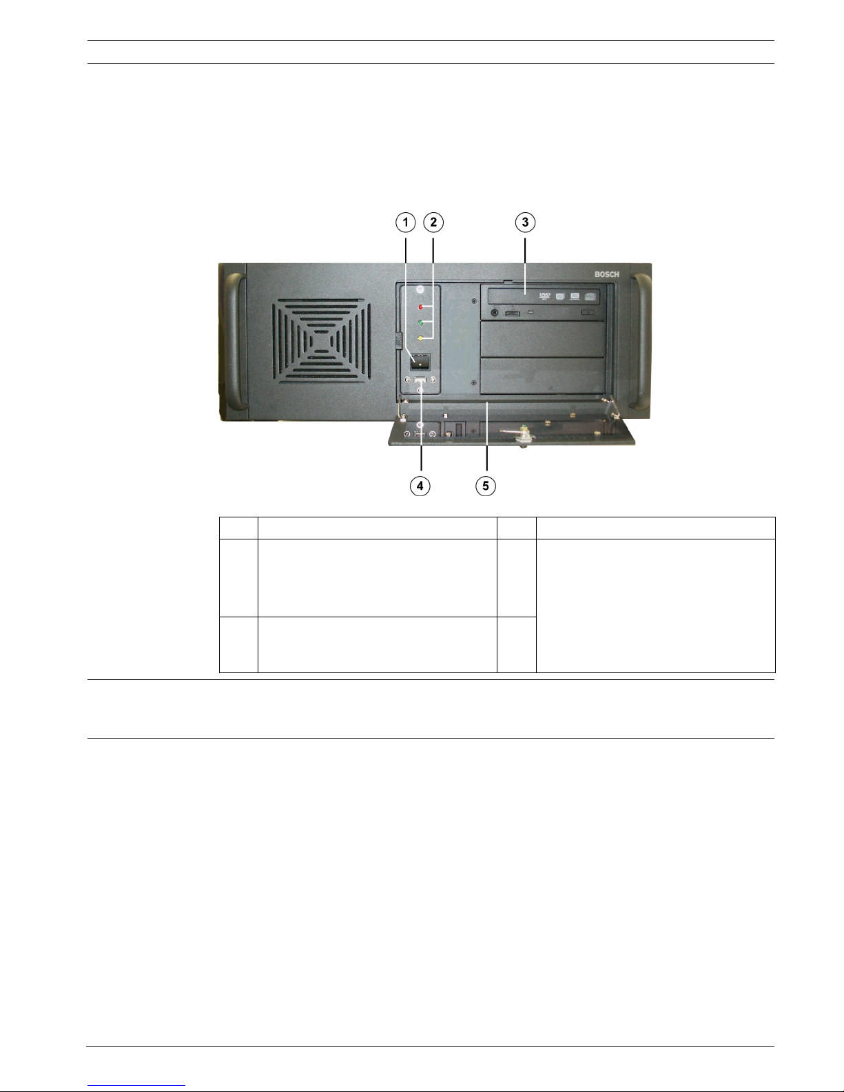
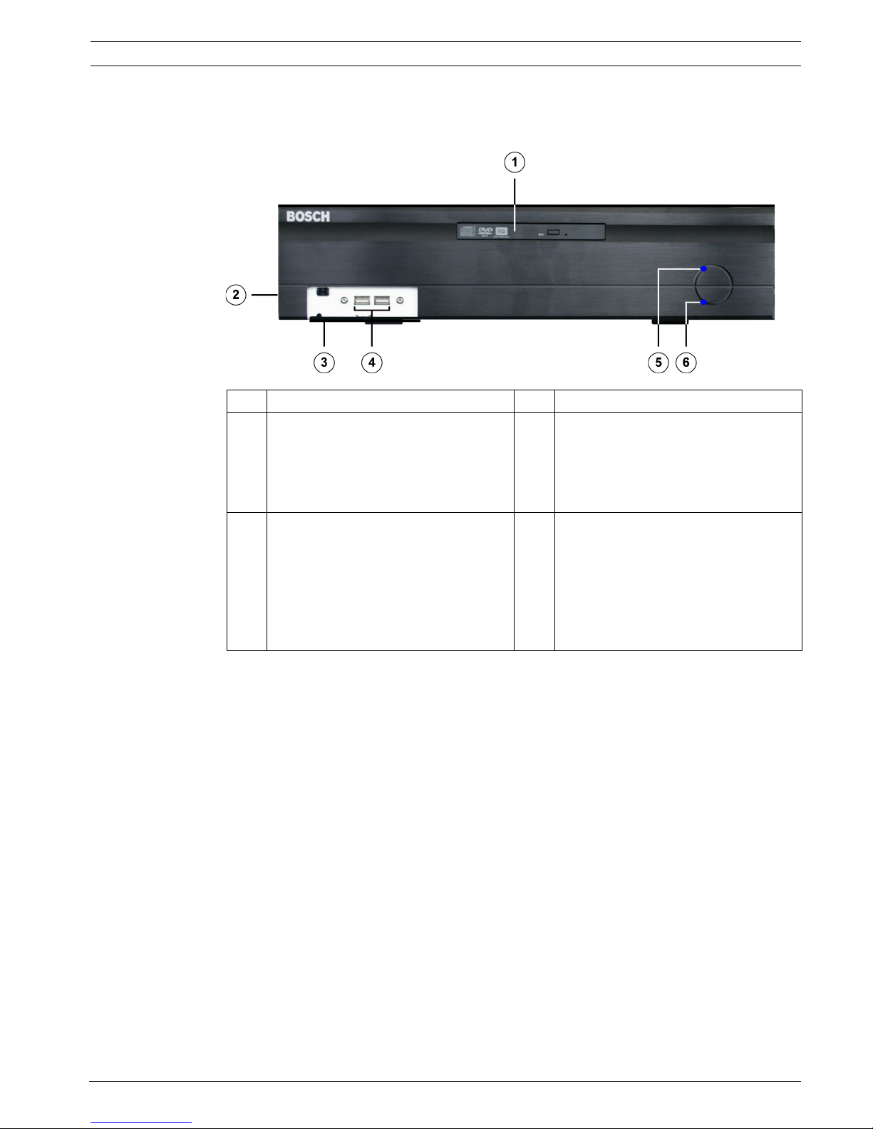
3.1.1 DiBos Front View
1On/Off switch 4USB 2.0
2 Status LEDs:
Red = hard disk access
Green = system is switched on
Yellow = unused
5 The following are located on the
device:
– Windows XP Embedded license
sticker
– DiBos rating plate
–DiBos license sticker and
activation key
3DVD-RW
CAUTION!
An air filter must not be installed in the device. Installing an air filter affects the cooling of the
device and can damage the device.
22 en | Device Connections DiBos/DiBos Micro
F.01U.033.308 | V7 | 2009.09 Installation Guide Bosch Sicherheitssysteme GmbH
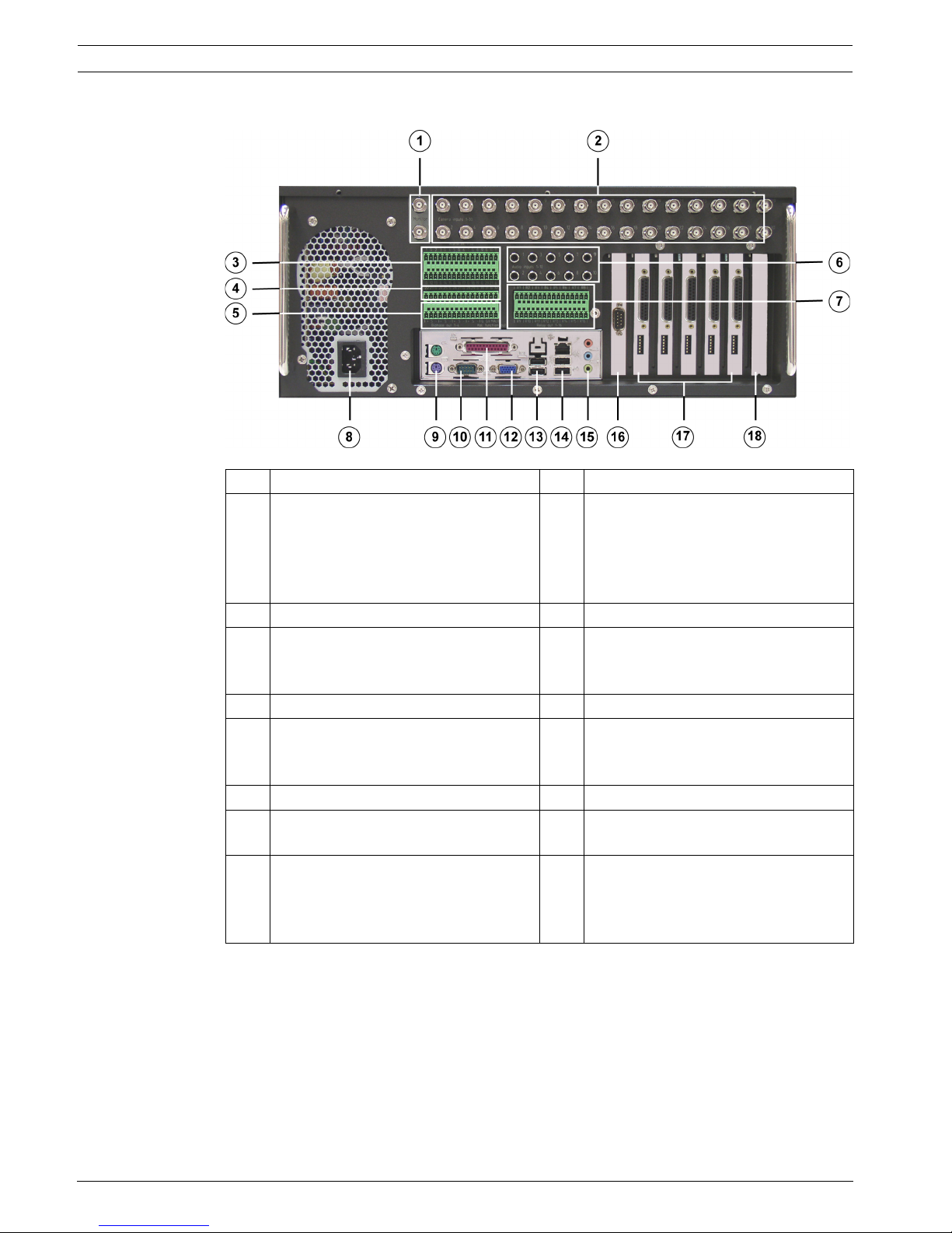
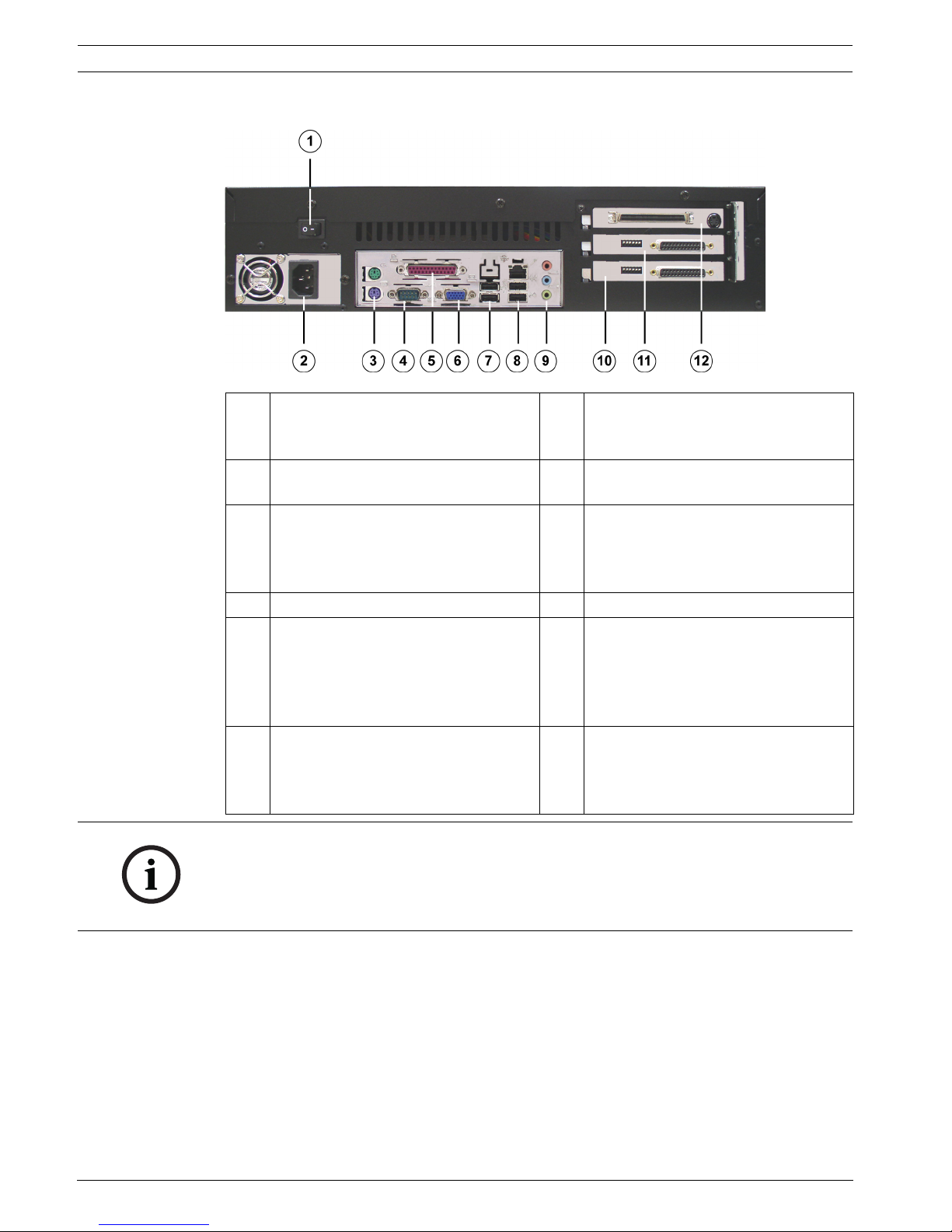
3.1.2 DiBos Rear View
1 Video monitor A/Video monitor B 10 Serial interface COM1
2 Video inputs 1 - 30 11 Parallel interface.
Note:
The HW dongle must be connected if
handling a device that has been
supplied with a HW dongle.
3 Alarm inputs 1 - 21 12 VGA monitor
4 Alarm inputs 22 - 32 13 2x USB 2.0
(e.g. for mouse and keyboard with
USB connection)
5 Biphase 1 - 4, malfunction outputs 1 14 1x Ethernet (RJ45) - 2x USB 2.0
6 Audio inputs 1 - 10 15 Line in (blue)
Speaker out (green)
Microphone in (red), mono
7 Relay outputs 1 - 16 16 Second serial interface (COM2)
8 Mains connection 100/240 VAC, 50/
60 Hz (automatic switchover)
17 Grabbers 1 - 5
9 Mouse (green) - Keyboard (purple).
These connections should be used if
the mouse and keyboard are not
connected via USB.
18 Free for optional PCI plug-in cards
DiBos/DiBos Micro Device Connections | en 23
Bosch Sicherheitssysteme GmbH Installation Guide F.01U.033.308 | V7 | 2009.09
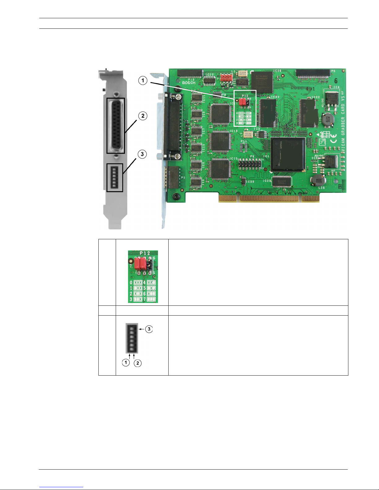
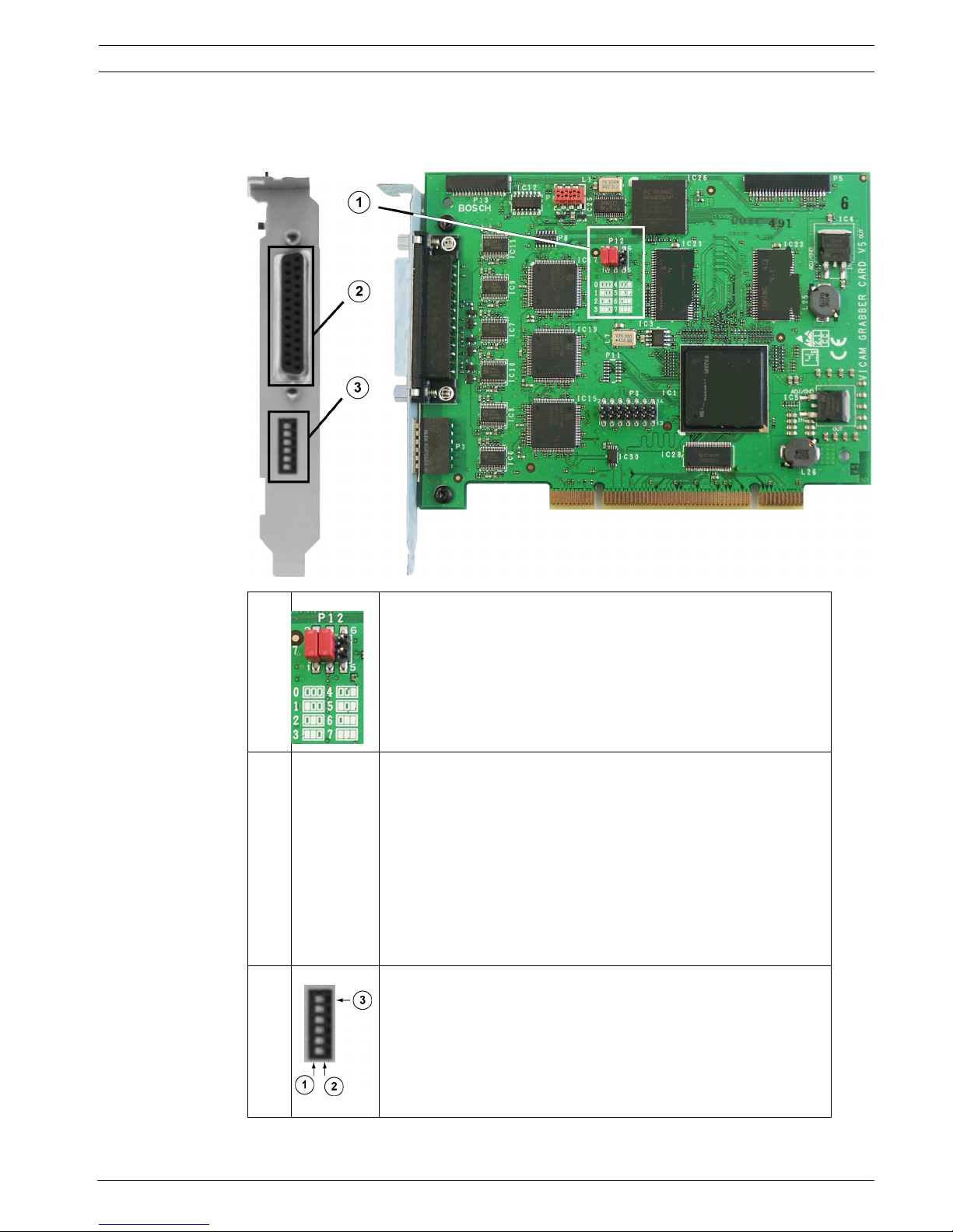
3.1.3 Grabber Card for DiBos
Looped through inputs may not be terminated. When a grabber card is retrofitted, the grabber
identification (grabber 1, grabber 2 etc.) must be set.
1 Grabber identification:
The setting for grabbers 1 - 5 is printed on the PCB.
0 = Grabber 1
1 = Grabber 2
2 = Grabber 3
3 = Grabber 4
4 = Grabber 5
2 Loopthrough cable plug
3 Termination when loopthrough cable is used:
1 = Switch position left: input terminated (position when
delivered)
2 = Switch position right: open, not terminated
3 = Topmost switch: for camera input 1 etc.
Note:
The positions relate to the illustration above.
24 en | Device Connections DiBos/DiBos Micro
F.01U.033.308 | V7 | 2009.09 Installation Guide Bosch Sicherheitssysteme GmbH
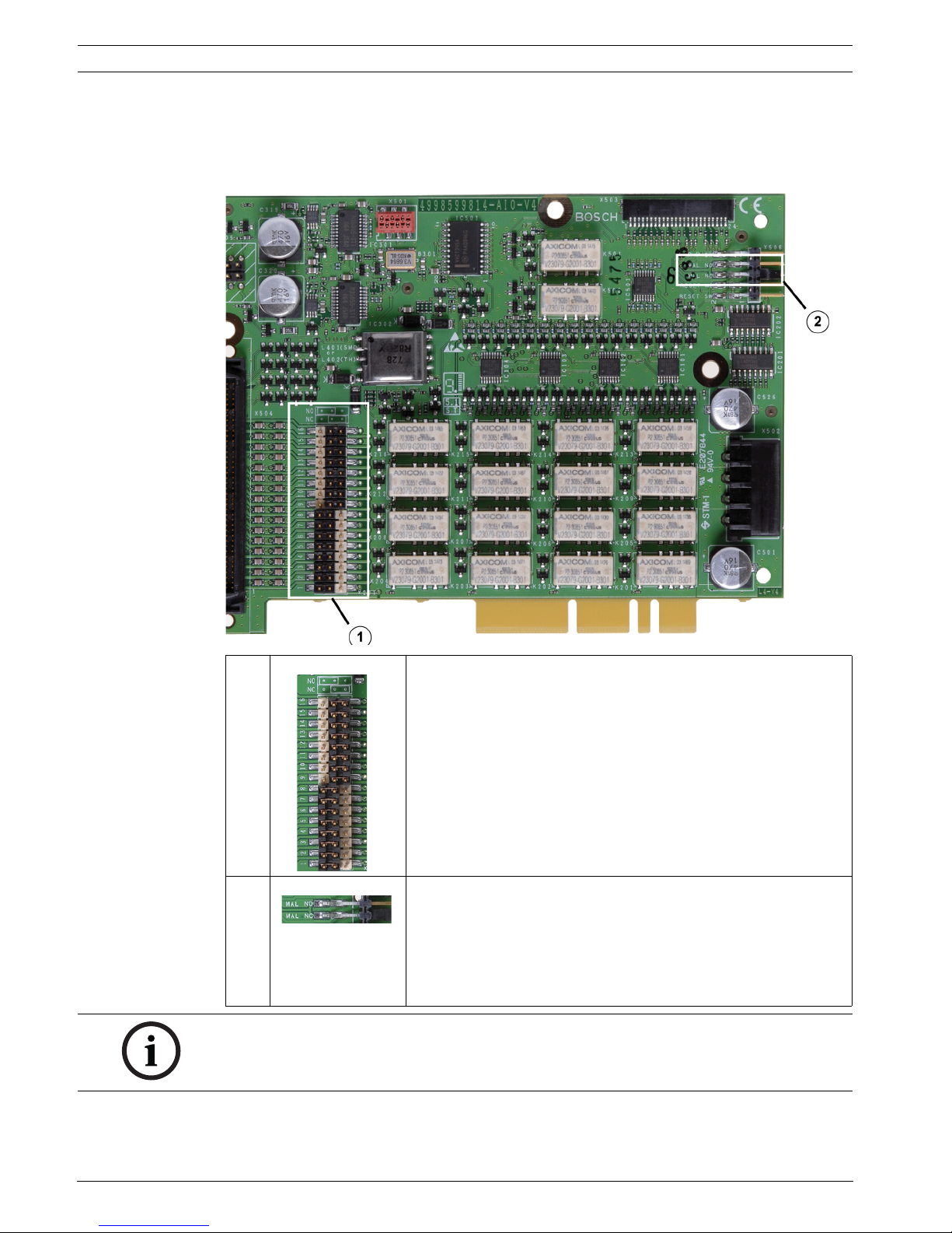
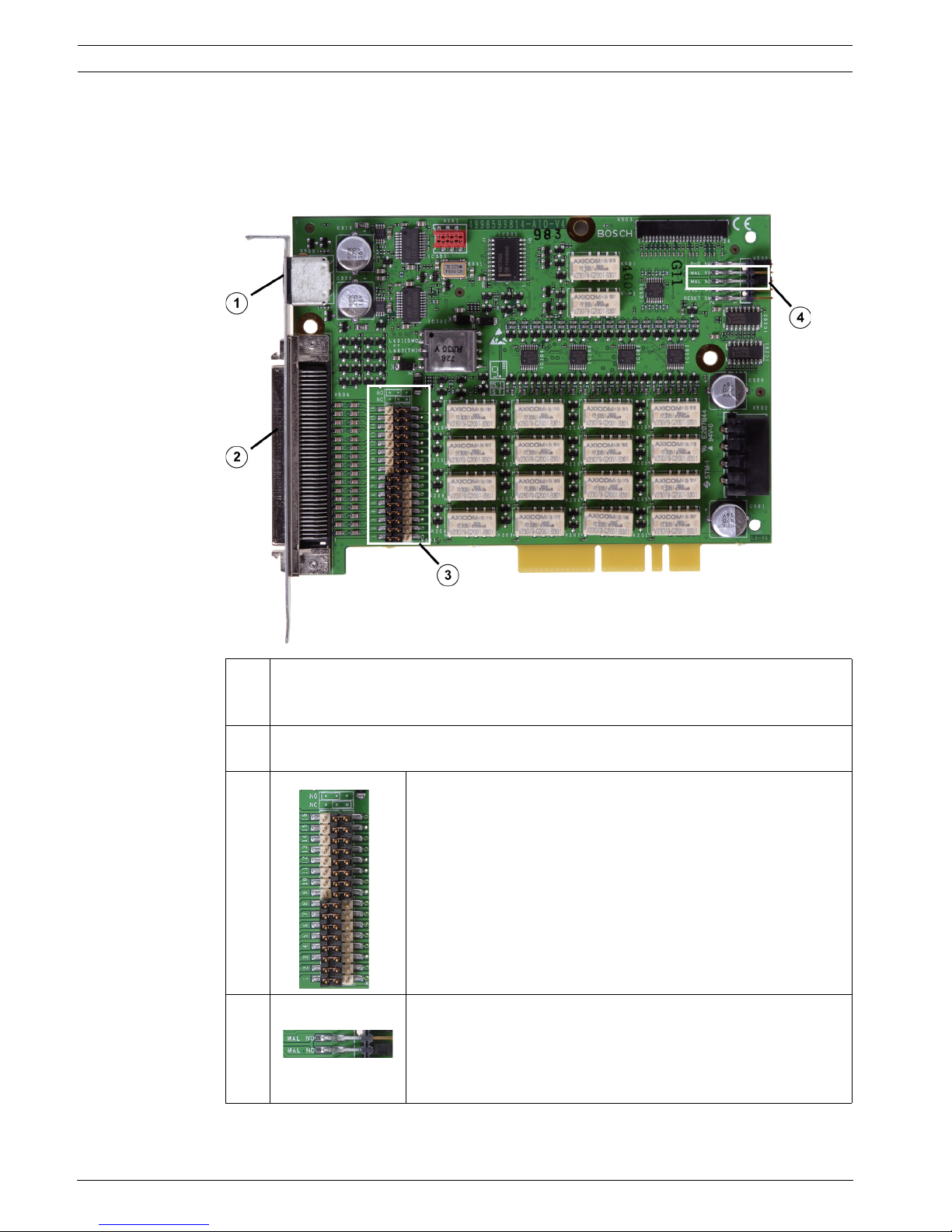
3.1.4 I/O Card for DiBos
The following can be set for the I/O card:
– the relay outputs (NO = normally open, NC = normally closed)
– the malfunction outputs (NO = normally open, NC = normally closed)
1 Relay outputs:
The setting is printed on the PCB.
Relay outputs 1–8: open (NO = normally open)
Relay outputs 9–16: closed (NC = normally closed)
2 Malfunction output:
The setting is printed on the PCB.
Bridge position up:
Open (MAL NO = malfunction normally open)
Bridge position down:
Closed (MAL NC = malfunction normally closed)
NOTICE!
The I/O card must be removed to change the bridge settings.
DiBos/DiBos Micro Device Connections | en 25
Bosch Sicherheitssysteme GmbH Installation Guide F.01U.033.308 | V7 | 2009.09
3.2 DiBos micro
3.2.1 DiBos micro Front View
1 DVD-RW 4 2x USB 2.0
2 The following are located on the side
panel:
– DiBos rating plate
– DiBos license sticker and
activation key
5 Status LED: System is switched on
3Front cover
Opened by pressing once on the
cover.
Note:
The Windows XP Embedded license
sticker is located on the inside of the
front cover.
6 Status LED: hard disk access
26 en | Device Connections DiBos/DiBos Micro
F.01U.033.308 | V7 | 2009.09 Installation Guide Bosch Sicherheitssysteme GmbH
3.2.2 DiBos micro Rear View
1 On/Off switch 7 2x USB 2.0
(e.g. for mouse and keyboard with
USB connection)
2 Mains connection 100 / 240 VAC, 50 /
60 Hz (automatic switchover)
8 1x Ethernet (RJ45) - 2x USB 2.0
3 Mouse (green) - Keyboard (purple).
These connections should be used if
the mouse and keyboard are not
connected via USB.
9 Line in (blue)
Speaker out (green)
Microphone in (red), mono
4 Serial interface COM1 10 Grabber 2 (camera 7 - 12)
5 Parallel interface.
Note:
The HW dongle must be connected if
handling a device that has been
supplied with a HW dongle.
11 Grabber 1 (camera 1 - 6)
6 VGA monitor 12 I/O card with plug for connecting the
alarm inputs and relay outputs and
socket for video monitor A and video
monitor B
NOTICE!
Ferrites must be fitted to the following cables:
– Network cable (2 ferrites directly next to each other)
–Keyboard (1 ferrite)
The ferrites must to be fitted to the cable directly next to the connections.
DiBos/DiBos Micro Device Connections | en 27
Bosch Sicherheitssysteme GmbH Installation Guide F.01U.033.308 | V7 | 2009.09
3.2.3 Grabber Card for DiBos micro
When a grabber card is retrofitted, the grabber identification (grabber 1, grabber 2 etc.) must
be set.
1 Grabber identification:
The setting for grabber card 1 and grabber card 2 is printed on
the PCB.
0 = Grabber 1
1 = Grabber 2
2 Plug for connecting cable with 6 video and 2 audio inputs (the
cables are numbered).
BNC cable number 1 (brown) = Video input 1
BNC cable number 2 (yellow) = Video input 2
BNC cable number 3 (green) = Video input 3
BNC cable number 4 (black) = Video input 4
BNC cable number 5 (white) = Video input 5
BNC cable number 6 (blue) = Video input 6
Audio cable number 1 (gray) = Audio input 1
Audio cable number 2 (red) = Audio input 2
3 Terminating video inputs:
1 = Switch position left: input terminated (position when
delivered)
2 = Switch position right: open, not terminated
3 = Topmost switch: for camera input 1 etc.
Note:
The positions relate to the illustration above.
28 en | Device Connections DiBos/DiBos Micro
F.01U.033.308 | V7 | 2009.09 Installation Guide Bosch Sicherheitssysteme GmbH
3.2.4 I/O Card (for DiBos micro)
The following can be set for the I/O card:
– the relay outputs (NO = normally open, NC = normally closed)
– the malfunction outputs (NO = normally open, NC = normally closed)
The I/O card must be removed to change the bridge settings.
1 Cable for monitor output A and monitor output B (the cables are numbered).
Cable number 1 = Monitor A
Cable number 2 = Monitor B
2 Connecting cable for 12 alarm inputs, 12 relay outputs, 3 biphase and 1 malfunction
output (for assignment, see table below)
3 16 relay outputs:
The setting is printed on the PCB.
Relay outputs 1–8: open (NO = normally open)
Relay outputs 9–16: closed (NC = normally closed)
4 Malfunction output: The setting is printed on the PCB.
Top bridge position: Open (MAL NO = malfunction normally
open)
Bottom bridge position (position when delivered): Closed (MAL
NC = malfunction normally closed)

DiBos/DiBos Micro Device Connections | en 29
Bosch Sicherheitssysteme GmbH Installation Guide F.01U.033.308 | V7 | 2009.09
I/O card pin assignment
Connector Color Name Connector Color Name
1 White/tan Relay 1 41 Tan/white Alarm input 1
2 White/brown Relay 1 42 Brown/white Alarm input 2
3 White/pink Relay 2 43 Pink/white Alarm input 3
4 White/orange Relay 2 44 Orange/white Alarm input 4
5 White/yellow Relay 3 45 Yellow/white Alarm input 5
6 White/green Relay 3 46 Green/white Alarm input 6
7 White/blue Relay 4 47 Blue/white Alarm input 7
8 White/purple Relay 4 48 Purple/white Alarm input 8
9 White/gray Ground 49 Gray/white Ground
10 Tan/brown Relay 5 50 Brown/tan Alarm input 9
11 Tan/pink Relay 5 51 Pink/tan Alarm input 10
12 Tan/orange Relay 6 52 Orange/tan Alarm input 11
13 Tan/yellow Relay 6 53 Yellow/tan Alarm input 12
14 Tan/green Relay 7 54 Unused
15 Green/tan Relay 7 55 Unused
16 Tan/blue Relay 8 56 Unused
17 Blue/tan Relay 8 57 Unused
18 Tan/purple Relay 9 58 Unused
19 Purple/tan Relay 9 59 Unused
20 Tan/gray Relay 10 60 Unused
21 Gray/tan Relay 10 61 Unused
22 Brown/pink Relay 11 62 Unused
23 Pink/brown Relay 11 63 Unused
24 Brown/orange Relay 12 64 Unused
25 Orange/brown Relay 12 65 Unused
26 Brown/yellow Ground 66 Yellow/brown Ground
27 Unused 67 Unused
28 Unused 68 Unused
29 Unused 69 Unused
30 Unused 70 Unused
31 Unused 71 Unused
32 Unused 72 Unused
33 Unused 73 Unused
34 Unused 74 Unused
35 Brown/green Malfunction
output
75 Green/brown Malfunction
output
36 Brown/blue Biphase 1- 76 Blue/brown Biphase 1+
37 Brown/purple Biphase 2- 77 Purple/brown Biphase 2+
38 Brown/gray Ground 78 Gray/brown Ground
39 Pink/orange Biphase 3- 79 Orange/pink Biphase 3+
40 Unused 80 Unused

30 en | Quick Installation DiBos/DiBos Micro
F.01U.033.308 | V7 | 2009.09 Installation Guide Bosch Sicherheitssysteme GmbH
4 Quick Installation
This chapter describes how to put the device into operation quickly and easily.
Main connections
1. Connect the cameras to the video inputs.
2. Make sure that the HW dongle is connected to the parallel interface (if you are handling a
device that has been supplied with a HW dongle).
3. Connect the VGA monitor.
4. Connect the mouse and keyboard.
Optional connections
The optional connections can be added after the system is configured.
1. Connect monitor A and monitor B to connections A and B.
2. Connect up to 32 alarm inputs (for DiBos micro: 12).
3. Connect up to 16 relay outputs (for DiBos micro: 12).
4. Connect your network via the Ethernet port.
5. Connect customer-operated ATMs, foyer card reader, radio clock and alarm panel.
Switching on
1. Switch on all connected devices.
2. Plug the power cable into the video system.
3. Switch on the video system (On/Off switch on the front). The computer boots up.
First-time use
Once the boot routine is complete, 1 image/second is stored for every camera connected.
The user interface is automatically displayed. This shows images from all connected cameras
in a multi-image view. If no images are displayed for a camera, check the camera connection.
You are not yet logged on as a user. You can, however, start the Configuration wizard.
Quick configuration with the help of the Configuration wizard
1. Start the Configuration wizard in the System menu > Configuration wizard.
2. Carry out a quick configuration in the Configuration wizard or load an existing
configuration onto the system.
 Loading...