

Page 1

Intrusion Alarm Systems
Databook EMEA 12/
2008
Page 2

Page 3

Control Panels, Control Centers, and Keypads 1
Accessories for Control Panels and Keypads 2
Software 3
Arming Devices 4
Detectors and Accessories 5
LSN Peripherals 6
Conettix - Information Transport Solutions 7
Wireless Local Security Network (wLSN) 8
DSRF Premises Wireless 9
Signaling Devices 10
www.boschsecurity.com Bosch Security Systems B.V.
Page 4

Bosch Security Systems B.V. www.boschsecurity.com
Page 5

Table of Contents | i
Control Panels, Control Centers,
and Keypads 1
Easy Series 2
Easy Series Intrusion Control Panel 2
IUI‑EZ1 Oval Control Center 9
ICP‑EZM2‑EU Intrusion Control Panel 10
ICP‑EZM2‑UK Intrusion Control Panel 10
ICP‑EZM2‑LC Intrusion Control Panel 11
ITS-300GSM Communicator 12
ICP‑EZPS‑FRA AFNOR Power Supply 14
ICP‑EZPS Wire‑in Power Supply 15
ICP‑EZPK Programming Key 15
Easy Series Voice Modules 16
Solution Series 20
CC408 Solution 880 Control Panel 20
CC488 Solution Ultima 880 Control Panel 22
CC880 Solution 16 Control Panel 24
VR8 Desktop Alarm System 27
CP500ALW Area Addressable LCD Codepad 29
CP500AW Area Addressable LED Codepad 30
CP500PW Partitionable LED Codepad 31
CP508W LED Codepad 32
CP516LW LCD Codepad 33
CP516W LED Codepad 34
DS7080i 35
DS7080iP32 Eight-zone Control Panels 35
7000 Line 38
DS7220V2 Control Panel 38
DS7240V2 Control Panel 42
DS7400Xi Series Addressable Control Panels 46
DS7446KP Series LCD Keypads 49
DS7447V2 Series LCD Keypads 51
DS7447E Series LCD Keypads 53
DS7445V2 Series LED Keypads 55
DS7445i Series LED Keypads 57
UEZ 2000 59
UEZ 2000/1 LSN, UEZ 2000 LSN, Intrusion Control
Centers 59
NZ 300 63
NZ 300 LSN Hold-up and Intrusion Control Panel 63
BE 300 LSN remote operating unit 66
Accessories for Control Panels and
Keypads 67
Interface Modules 82
Conettix DX4020 Ethernet Network Interface
Module 82
Conettix C900V2 Dialer Capture Ethernet Module 84
DX4010i RS‑232 Serial Interface Module 87
DS7420i Dual Phoneline/Bell Supervision Module 89
Door Access Control Modules 91
Door Access Control Module (DACM) 91
IUI‑CARD/DACM Proximity Cards 93
IUI‑FOB/DACM Proximity Key Fobs 94
IUI‑CABLE/DACM Cable 94
IUI‑CNTRL/DACM Controller 95
IUI‑DTU/DACM Data Transfer Unit (DTU) 95
IUI‑READER/DACM Proximity Reader 96
IUI‑READKP/DACM Proximity Reader with Keypad 96
IUI‑SWCD/DACM PC Software 97
Enclosures 98
AE1 Standard Enclosure (Gray) 98
AE3 Large Enclosure (Gray) 98
AE20 Universal Plastic Enclosure 99
D203 Enclosure 99
Power Supplies and Batteries 100
Battery 12 V / 10 Ah 100
Battery 12 V / 17 Ah 101
Battery 12 V / 24 Ah 102
Battery 12 V / 65 Ah 103
D1222 Battery (12 V, 2.2 Ah) 104
D1250 Battery (12 V, 5 Ah) 105
D126 Standby Battery (12 V, 7 Ah) 106
ICP‑EZPS Wire‑in Power Supply 107
ICP‑EZPS‑FRA AFNOR Power Supply 107
NEV 300 LSN power supply 108
Cables, Switches, and Programmers 110
ICP‑EZPK Programming Key 110
CC808 Direct Link Cable 110
Control Center and Keypad Accessories 111
IUI‑EZT‑5 Easy Series Token Package 111
Software 113
Programming Software 114
Remote Programming Software International 114
WDSRP Remote Programming
Software for Windows 116
Expansion Modules 68
DX2010 Series Input Expander 68
DX3010 Series Octo‑output Expander 69
DS7430 Multiplex Expansion Module 70
DS7432 Series Eight‑input Remote Modules 71
DS7433 Series Eight‑input Modules 73
DS7436 Multiplex Expansion Module 74
DS7457i Series Single Zone Input Modules 75
DS7457iE Single Zone Input Module 77
DS7460i Dual‑zone Input Module 78
DS7465i Input‑Output Module 80
www.boschsecurity.com Bosch Security Systems B.V.
Arming Devices 119
Conventional 120
SE 50 GLT SmartKey Blocking Unit 120
SE 100 GLT SmartKey Arming Device 122
LSN 124
SE 60 LSNi SmartKey Blocking Unit 124
SE 120 LSNi SmartKey Arming Device 126
SE 220 LSNi SmartKey Arming Device 128
SE 320 LSNi SmartKey Arming Device 131
Page 6

ii | Table of Contents
Detectors and Accessories 135
Motion PIR 136
ISC‑PPR1‑W16 Professional Series PIR Detector 136
ISC‑PPR1‑WA16x Professional Series PIR
Detectors with Anti‑mask 139
ISM‑BLP1 Blue Line PIR Detector 142
ISM‑BLP1‑P Blue Line Pet‑Friendly PIR Detector 145
ISM‑BLQ1 Blue Line Quad PIR Detector 148
DS306E PIR Detector 151
DS308EA Quad PIR Detector with Anti-mask 153
MX775i Multiplex PIR Intrusion Detector 156
MX934i Multiplex PIR Intrusion Detector 159
DS304 PIR Detector with Replaceable Mirrors 162
Motion PIR/Microwave 164
ISC‑PDL1‑W18x Professional Series TriTech
Detectors 164
ISC‑PDL1‑WA18x Professional Series TriTech+
Detectors with Anti‑mask 168
ISM‑BLD1 Blue Line TriTech Detectors 172
ISM‑BLD1‑P Blue Line Pet Friendly TriTech
Detectors 174
DS825 and DS840 Series TriTech PIR Detectors 177
DS860 Series TriTech PIR/Microwave Detector 180
Motion Outdoor 183
OD850 Series Outdoor TriTech Detectors 183
Motion Ceiling Mount 186
DS936 Low Profile Panoramic PIR Detector 186
DS937 Panoramic Detector 188
DS938Z and ZX938Z Series Panoramic
PIR Detectors 190
DS939 Panoramic Detector 192
DS9360 Panoramic TriTech Detector 194
DS9370 Series Panoramic TriTech Detector 196
DS9371 Panoramic TriTech Detector 198
MX938i Multiplex Intrusion Detector 200
Motion Long Range 202
DS720i Long Range TriTech PIR Detector
(10.525 GHz) 202
DS778 Long Range PIR Detector 205
DS794Z and ZX794Z Series Long Range PIR
Detectors 207
MX794i Long Range Multiplex PIR Detector 209
Request-to-Exit 211
DS150i Series Request-to-exit Detectors 211
DS160 Series High Performance Request‑to‑exit
Detectors 213
Glass Break 216
DS1100i Series Glassbreak Detectors 216
DS1109i Glassbreak Detector 218
Seismic 220
ISN-SM Seismic Detectors 220
Photoelectric Beam 223
DS415i and DS435i Single Beam Photoelectric
Detectors 223
DS422i and DS426i Dual‑Beam Photoelectric
Detectors 225
DS453Q and DS455Q Quad Beam Photoelectric
Detectors 226
DS484Q and DS486Q Quad‑Beam Photoelectric
Detectors 228
Holdup 230
ND 100 GLT Panic Button 230
Smoke 231
F220 Photoelectric Smoke Detectors 231
F220 Heat Detectors 234
F220‑B6 Series Conventional Detector Bases 236
F220‑B6RS 24 VDC Four‑wire Detector Base with
Sounder 238
Magnetic Contacts Recessed Mount 240
ISN‑CSTB‑10 Compact Contacts (9.5 mm) 240
ISN‑CSTB‑10DM Contacts with Thin Magnet
(9.5 mm) 241
ISN‑CSTB‑TC Terminal Connection Contacts
(16 mm) 242
ISN‑CTC75 Terminal Connection Contacts
(19 mm) 244
ISN‑CTAP‑10 Contacts (9.5 mm) 245
ISN‑CTAP‑15 Contacts (6.35 mm) 247
ISN‑CRFM‑25 Oval Flange Contacts (6.35 mm) 248
ISN‑CMINI‑10 Miniature Contacts (9.5 mm) 249
ISN‑CMINI‑10D Miniature Contacts with Thin
Magnet (9.5 mm) 250
ISN‑CMINI‑15 Miniature Contacts (6.35 mm) 251
ISN‑C22 Compact Ball Reed Contacts 252
ISN‑CPB52 Reed Plunger Contacts 253
ISN‑CAS Adjustable Screw Head Contacts 255
ISN‑CRB32 Roller Ball Contacts 256
ISN‑CSD70 and ISN‑CSD80 Compact Contacts 257
EMK 46 S Z Flush-Mount Magnetic Contact 259
EMK 46 Z Built-in magnetic contact 261
MS-LZ Flush-Mount Magnetic Contact 262
MS-LZS Flush-Mount Magnetic Contact 263
ADM 2000 Spring-loaded mechanism 264
ADB Spring-loaded bolts for wooden windows 265
Magnetic Contacts Surface Mount 266
ISN‑CMICRO Ultra Miniature Contacts 266
ISN‑C50 Terminal Connection Contacts
with Cover 267
ISN‑C60 Slim Terminal Connection Contacts 268
ISN‑CSM35 Standard and Wide Gap Contacts 269
ISN‑CSM20‑WG Commercial Contacts 270
ISN‑CSS‑40 Super Stick Contacts with Side Leads 271
ISN‑C45 Miniature Super Stick
Contacts with Side Leads 272
ISN‑CFM‑102 Flange Mount Contacts with Side
Leads 273
ISN‑CFM‑106 Flange Mount Contacts with Center
Leads 274
ISN‑CMET‑4418 Overhead Door Contact 275
ISN‑CMET‑200AR Commercial Metal Contact 276
ISN‑C66 Track Mounted Overhead Door Contact 277
EMK 46 AT Z Surface-Mount Magnetic Contact 278
MK 48 SZ surface-mount magnetic contact 280
MSA-LZ Surface-Mount Magnetic Contact 282
MSA-LZS Surface-Mount Magnetic Contact 283
AMK 4 Z Overhead door contact 284
AMK 4 S Z Shutter Door Contact 285
Accessories 286
ISM‑BLA1‑CC Blue Line Color Camera Modules 286
ISM‑BLA1‑LM Blue Line Nightlight Module 288
Bosch Security Systems B.V. www.boschsecurity.com
Page 7

Table of Contents | iii
ISM‑BLA1‑SM Blue Line Sounder Module 290
B328 Gimbal‑mount Bracket 291
Swiveling B335-3 low-profile mount 292
B800 Ceiling‑mount Bracket 292
DS1110i Glassbreak Tester 293
MP1 Metal Pole, 1 m (3 ft) 293
MP2 Metal Pole, 1.2 m (4 ft) 294
MP3 L‑Curved Metal Pole 294
OA120‑2 Mirror 295
OLR92‑3 Long‑range Lens 295
OMB77‑3 Barrier Mirror 296
OMLR77‑3 Long‑range Mirror 296
OMLR93‑3 Long‑range Mirror 297
PC1A Weather Enclosure 297
PEH‑2 Heater 298
TP160 Trim Plate 299
TP161 Trim Plate 299
LSN Peripherals 301
LSN Motion PIR/Microwave 302
ISP‑PPR1‑WA16x Professional Series LSN PIR
Detectors with Anti‑mask 302
ISP‑PDL1‑WA18x Professional Series LSN TriTech
+ Detectors with Anti‑mask 306
DS 935 LSN Infrared Motion Detector 310
DS840LSN TriTech PIR/MW Dual Motion Detector 312
IR 200 LSN Infrared Motion Detector 314
IR 270 T LSNi Infrared Motion Detector, Antimask 317
UP 370 T LSN Matchtec Detector, Antimask 320
LSN Seismic 322
GM 570 LSN Seismic Detector 322
LSN Glassbreak 325
GBS 2036 LSN Passive Glass Break Detector 325
LSN Smoke 327
MAGIC.SENS Automatic LSN Fire Detectors 327
MAGIC.SENS Detector Base Sounders 331
FAP‑520 Automatic Fire Detectors LSN improved
version 334
FAP‑420/FAH‑420 Automatic Fire Detectors LSN
improved version 339
LSN Magnetic Contacts 343
EMK 36 LSN Built-in Magnetic Contact 343
EMK 36 AT LSN Surface-Mount Magnetic Contact 345
EMK 36 S LSN Built-In Magnetic Contact 347
MK 36 S LSN Surface-Mount Magnetic Contact 349
MSE-LSN B Built-In Magnetic Contact 351
MSA-LSN B Surface-Mount Magnetic Contact 353
MSE-LSN C Built-In Magnetic Contact 355
MSA-LSN C Surface-Mount Magnetic Contact 357
AMK 4 LSN Shutter Door Contact 359
AMK 4 S LSN Shutter Door Contact 361
SKA 100 LSN Bolt Contact 363
SKI 100 LSN Bolt Contact 365
LSN Holdup 366
ND 200 LSN Panic Button 366
LSN Expansion Modules 367
IPB-IF100 LSN 16 Zone Expander Module 367
NAK 100 LSN Branch Interface 369
NNK 110 LSN Emergency Call Coupler 371
NVK 100 LSN Coupler 374
IC 400 LSN Universal Expander 377
KD 55/1 LSN 2 Zone Expander Modules 379
LSN Display Panels 381
BAT 100 LSN Display Panel 381
LSN Power Supplies 383
NEV 300 LSN power supply 383
Conettix - Information Transport
Solutions 385
Conettix - Receiver/Gateway 386
Conettix D6600 Communications Receiver/
Gateway 386
Conettix D6100 Communications Receiver/
Gateway 391
Conettix D6100i Communications Receiver/
Gateway 395
Conettix - Receiver/Gateway Accessories 399
D6600 CD ROM 399
Conettix D6200CD CD‑ROM 399
Conettix D6641 Telephone Line Card 400
Conettix D6645 Telephone Line Terminator Card 400
Conettix D6672 Com 1 Expansion Kit 401
Conettix D6680 Ethernet Network Adapter 402
Conettix D6610 CPU Line Card 403
Conettix D6615 CPU Terminator Card 404
P6601 Battery Cable 404
P6602 Input and Output Cable 405
P6603 Acknowledgement Button 405
Conettix D6100 Rack Mount Kit 406
Conettix GSM 407
ITS-300GSM Communicator 407
Conettix IP 409
Conettix D6680 Ethernet Network Adapter 409
Conettix D6201 Series IP Security Keys 411
Conettix C900V2 Dialer Capture Ethernet Module 412
Conettix DX4020 Ethernet Network Interface
Module 415
Conettix - AT2000/ATE 417
AT 2000 Analog Transmission System 417
AT 2000 ISDN Transmission System 419
AT 2000 TSN ISDN Transmission System 421
AT 2000 IP ISDN Transmission System 424
ATE TSN ISDN Alarm Receiver 427
Wireless Local Security Network
(wLSN) 429
wLSN Peripherie 430
wLSN Hub 430
wLSN Relay Module 432
wLSN Siren (Indoor) 434
wLSN Door‑Window Contact 436
wLSN Smoke Detector for Europe 438
wLSN Glassbreak Detector 440
wLSN Inertia Sensor 442
wLSN Dual Motion Detectors 444
www.boschsecurity.com Bosch Security Systems B.V.
Page 8

iv | Table of Contents
wLSN PIR Motion Detector 447
wLSN Key Fob 450
wLSN Mini Door‑Window Contact 452
wLSN Recessed Door‑Window Contact 454
wLSN Water Sensor/Low‑temperature Sensor 456
wLSN Accessories 458
wLSN Installation Tool 458
DSRF Premises Wireless 461
Bosch DSRF Receivers 462
RF3212 Series RF Receivers 462
RF3222E RF Receiver (433.42 MHz) 464
RF3227E RF Receiver (433.42 MHz) 466
Bosch DSRF Transmitters 468
RF280THS Series Wireless Photoelectric
Smoke Detectors 468
RF835 Series Wireless TriTech Detectors 470
RF940E Wireless PIR Detector 473
RF1100E Glassbreak Transmitter 475
RF3332 Series Key Fobs 477
RF3334 Series Key Fobs 479
RF3401 Series RF Point Transmitters 481
RF3405E Wireless (RF) Inertia Transmitter 483
RF3501LE Panic Transmitter (433.42 MHz) 485
RF3503E Panic‑Medical Fob 487
Signaling Devices 489
Signaling Devices 490
BES External Signaling Device, Audio/Visual 490
BL 200 Strobes 492
Bosch Security Systems B.V. www.boschsecurity.com
Page 9

Control Panels, Control
Centers, and Keypads
1
Easy Series 2
Solution Series 20
DS7080i 35
7000 Line 38
UEZ 2000 59
NZ 300 63
www.boschsecurity.com Bosch Security Systems B.V.
Page 10
2 | Control Panels, Control Centers, and Keypads | Easy Series
1
Easy Series Intrusion Control Panel
Features
Supports up to 32 total input points (hard-wired,
▶
wireless, or combination)
Advanced false alarm reduction
▶
Integrated proximity reader
▶
Speaks language of choice
▶
wireless Local SecurityNetwork (wLSN) support
▶
Remote Programming Software (RPS) support
▶
Simple icon-based control center
▶
Integrated digital dialer, voice dialer, text messaging,
▶
and two-way audio verification
Designed for residential and small commercial applications,
the Easy Series Intrusion Control Panel requires minimal
training and support and is easy to install, configure, and
test. The control center speaks while showing animated
icons, so that the user quickly understands the information
and tasks.
Optional wireless Local SecurityNetwork (wLSN) support is
available in Europe. wLSN provides two-way wireless
communication using the 868 MHz security band, easy
installation, automatic configuration, and a variety of
wireless devices.
Note wLSN support is available only in Easy Series
Intrusion Control Panels, Release 2
(ICP‑EZM2) or later.
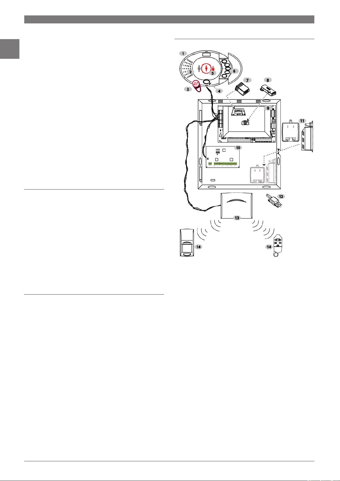
System Overview
1. Control Center
2. Sensor and Audio Components
3. Radio Frequency Identification (RFID) Reader and Token
4. Information Button
5. Icon Indicators
6. Function Buttons
7. Voice Module
8. Programming Key
9. Easy Series Intrusion Control Panel
10. DX2010 Input Expander Module
11. Power Supplies
The Easy Series Intrusion Control Panel can use a wired-in power supply or transformer, according to regional primary voltage input requirements.
12. Optional Dual Tamper Switch
13. Optional wireless Local SecurityNetwork (wLSN) Hub
14. Optional wLSN Devices
Terminal Blocks
Easy Series terminal blocks are color-coded to clearly show
where to connect the power supply, telephone line, control
center, and assorted devices such as smoke detectors or
motion detectors. Each input and output has a dedicated
pair of terminals, making installing and wiring the system
easier to understand and execute.
Bosch Security Systems B.V. www.boschsecurity.com
Page 11

Control Panels, Control Centers, and Keypads | Easy Series | 3
Functions
Advanced False Alarm Reduction
The Easy Series Intrusion Control Panel system guards
against user-generated false alarms through design features
such as Graduated Annunciation and Intelligent Threat
Assessment. Easy Series uses enhanced false alarm
verification methods that exceed industry false alarm
reduction standards.
Graduated Annunciation
The system gradually increases the control center volume,
changes the animation of the control center display, and
incrementally pulses the warning devices. The control
center notifies users when the system is preparing to send
an alarm and provides options to cancel reports, reducing
false alarms.
Alarm Verification
The following alarm verification methods reduce false
alarms without compromising usability or reliability.
1. Two-way Audio Verification: Provides remote customers
the ability to listen to and speak with users at the
protected premises.
2. Sequential Verification: When two or more input
sensors activate within a specified time period, an
intrusion alarm is considered verified. For example, if a
door sensor and a motion detector both sense alarms,
the system sends a verified alarm report.
3. Intelligent Threat Assessment: The Easy Series Intrusion
Control Panel uses protection levels, input types, input
conditions, and system event timing to assess a
potential threat. If the threat reaches a specific
threshold, the system sends a verified alarm report.
Easy Series Intrusion Control Panel Configuration
Users can configure the Easy Series Intrusion Control Panel
with the necessary regional parameters for a specific
country without changing hardware. Installers can
configure the system using their language of choice and
then set the system to the appropriate language for the
user. Installers can remotely program the system using a
telephone or Remote Programming Software (RPS). A voice
prompted installer mode reduces service and installation
costs while ensuring accurate programming.
Remote Programming Software (RPS)
RPS is a separate software package that allows computers
equipped with the Microsoft Windows operating system
and a modem to act as a remote programming, record
storage, remote control, and troubleshooting tool for
specific control panels.
Certifications and Approvals
1
Region Certification
Europe CE 1999/5/EC, 2006/95/EC, 2004/108/
EC; EN 55022:2006 + A1:2007, Class B;
EN 50130-4 w/A1:1998 + A2:2003;
EN61000-3-2:2006;
EN61000-3-3:1995; EN 60950-1:2001;
TBR21:1998
Belgium INCERT B-509-0044/b
USA UL AMCX: Central Station Alarm Units
(UL1610, UL1635), AMCX7: Central
Station Alarm Units Certified for Canada
(cULus), AMTB: Control Panels, SIA False
Alarm Reduction, AOTX: Local Alarm Units
(UL464, UL609), AOTX7: Local Alarm
Units Certified for Canada (cULus), APAW:
Police Station Alarm Units (UL365,
UL464), APAW7: Police Station Alarm
Units Certified for Canada (cULus), APOU:
Proprietary Alarm Units (UL1076),
APOU7: Proprietary Alarm Units Certified
for Canada (cULus), NBSX: Household
Burglar Alarm System Units (UL1023),
NBSX7: Household Burglar Alarm System
Units Certified for Canada (cULus), UTOU:
Control Units and Accessories - Household
System Type (UL985), UTOU7: Control
Units and Accessories - Household System
Type Certified for Canada (cULus)
CSFM 7167-1615: 223 July 2008
Canada IC 1249A-EZM1
Sweden INTYG Nr08-423 Centralapparat
Nr08-424 Centralapparat-trådlös
Compliance with specific standards, such as SIA CP-01 and DD243, reduces
false alarms and is required in many locations. In addition to the certifications
and approvals listed above, the Easy Series Intrusion Control Panel is designed to comply with the following certifications, approvals, and standards:
EN50131-1 Grade 2
DD243
PD6662
CCC
FCC
A-Tick
C-Tick
TBR21 for PSTN
Japan Approvals Institute for Telecommunications Equipment (JATE)
www.boschsecurity.com Bosch Security Systems B.V.
Page 12

4 | Control Panels, Control Centers, and Keypads | Easy Series
1
Installation/Configuration Notes
Compatibility Information
PSTN Communicator
(Integrated)
IP Communicator
GSM Communica-
1, 3
tor
Radio Communicators (SAFECOM)
Magnetic Contacts
Intrusion Detectors
Two-wire and
Four‑wire Smoke De-
1,3
tectors
Hardwire Expansion
Module
Interface Module
wireless Local SecurityNetwork (wLSN)
1
Devices
1
Assorted literature is available. Refer to the appropriate data sheet, bro-
chure, installation guide, or user guide for additional details.
2
Only sold in specific countries. Does not comply with CE.
3
Availability varies according to sales regions.
Formats: BSIA Fast Format, Contact ID, SIA,
(Voice Dialer)
Personal Messaging: SMS Text and Voice
1, 3
Conettix IP C900V2 Dialer Capture Module
Conettix ITS-300GSM Communicator
SC2104 Series Slave Communicators
1, 2
SC3100 Series Data Transfer Radio Communicators
SC4000 Series Full Data Transfer Radio Communicator
1
All Bosch magnetic contacts, including recessed,
terminal connection, miniature, overhead door,
and surface mount.
1
All conventional Bosch intrusion detectors, including Blue Line, seismic, PIR, TriTech, photoelectric,
and TriTech PIR Microwave.
Conventional Bosch 12 V smoke, heat, and photoelectric smoke detectors.
DX2010 Input Expander
1, 2
D132A Smoke Detector Reversing Relay
All Bosch wLSN devices, including the wLSN Hub
(wireless expansion module), wLSN PIR and dual
technology motion detectors, wLSN glass break
detectors, wLSN key fobs, wLSN inertia sensors,
wLSN door and window contacts, wLSN relay outputs, and wLSN sirens.
Input Points
Maximum Number of Input
Points:
Hardwire, Wireless, or
Combination Input Points:
Hardwire Expansion Input
Points:
Wireless Expansion Input
Points:
Outputs
On-board: Four
Wireless: Four
Number of…
Control Centers: Four
DX2010 Expansion Modules:
wLSN Hubs: One on the Option Bus
Users: Up to 20 (20 passcodes, 20 tokens, and 20
Events: 500 history events, stamped with time and date
Power Requirements
32
Eight on-board
Hard-wire single, zone-doubling, dual
•
end-of-line (EOL) tamper, or wireless.
Input 1 also supports two-wire smoke
•
detectors, all input points support fourwire detectors.
Enclosure tamper input (does not reduce
•
input point capacity).
Up to 24 with three DX2010 Input Expander
Modules (32 total).
Each DX2010 provides eight additional input
points. The Easy Series Intrusion Control Panel
supports up to three modules.
Up to 32 with the wLSN Hub
Configurable solid state
•
Internal siren driver option for speakers
•
(output 4 only)
Audible voice prompts included
•
Accepts passcodes, token, or the wLSN
•
key fob for user arming and disarming
Three on the Option Bus
wLSN key fobs)
Technical Specifications
Dimensions
Control Center: 12 cm x 17.7 cm x 2.5 cm
(4.7 in. x 7 in. x 1 in.)
AE1 Enclosure: 37 cm x 31.75 cm x 8.5 cm
(14.5 in. x 12.5 in. x 3.4 in.)
Environmental Considerations
Relative Humidity: 93% ±5% at 32°C ±2°C (+90°F ±2°F)
Temperature (Operat-
ing):
Temperature (Storage): -10°C to +55°C
Environmental Class II
-10°C to +49°C
(+14°F to +120°F)
(+14°F to +130°F)
Primary Voltage Source: 110 V, +10% or -15% (47 Hz to 62 Hz)
230 V, +10% or -15% (47 Hz to 62 Hz)
Primary Voltage Input
(AC):
Primary Voltage Input
(DC):
Secondary Voltage Input
(DC):
Total Power: 1.4 A
Auxiliary Power: 1.0 A
Easy Series Kit Ordering Information
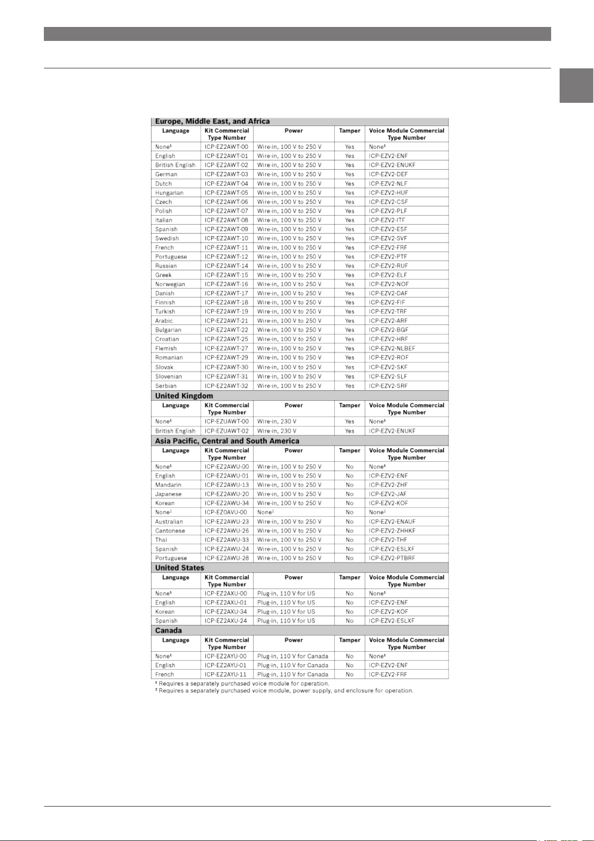
Europe, Middle East, and Africa
Kits include one control panel, enclosure, tamper switch, oval control center, wire‑in power supply (100 V to 250 V), and two RFID tokens unless
noted otherwise.
Language Commercial Type Numbers
1
None
1
None
English ICP‑EZ2AWT‑01 ICP‑EZV2‑ENF
18 V (47 Hz to 62 Hz)
18 V non-polarized
12 VDC, 7 Ah or 18 Ah sealed lead acid rechargeable battery
Kit Voice Module
ICP‑EZUAWT‑00
ICP‑EZ2AWT‑00
2
None
None
1
1
Bosch Security Systems B.V. www.boschsecurity.com
Page 13

Control Panels, Control Centers, and Keypads | Easy Series | 5
Easy Series Kit Ordering Information
Europe, Middle East, and Africa
British English ICP‑EZ2AWT‑02 ICP‑EZV2‑ENUKF
German ICP‑EZ2AWT‑03 ICP‑EZV2‑DEF
Dutch ICP‑EZ2AWT‑04 ICP‑EZV2‑NLF
Hungarian ICP‑EZ2AWT‑05 ICP‑EZV2‑HUF
Czech ICP‑EZ2AWT‑06 ICP‑EZV2‑CSF
Polish ICP‑EZ2AWT‑07 ICP‑EZV2‑PLF
Italian ICP‑EZ2AWT‑08 ICP‑EZV2‑ITF
Spanish ICP‑EZ2AWT‑09 ICP‑EZV2‑ESF
Swedish ICP‑EZ2AWT‑10 ICP‑EZV2‑SVF
French ICP‑EZ2AWT‑11 ICP‑EZV2‑FRF
Portuguese ICP‑EZ2AWT‑12 ICP‑EZV2‑PTF
Russian ICP‑EZ2AWT‑14 ICP‑EZV2‑RUF
Greek ICP‑EZ2AWT‑15 ICP‑EZV2‑ELF
Norwegian ICP‑EZ2AWT‑16 ICP‑EZV2‑NOF
Danish ICP‑EZ2AWT‑17 ICP‑EZV2‑DAF
Finnish ICP‑EZ2AWT‑18 ICP‑EZV2‑FIF
Turkish ICP‑EZ2AWT‑19 ICP‑EZV2‑TRF
Arabic ICP‑EZ2AWT‑21 ICP‑EZV2‑ARF
Bulgarian ICP‑EZ2AWT‑22 ICP‑EZV2‑BGF
Croatian ICP‑EZ2AWT‑25 ICP‑EZV2‑HRF
Flemish ICP‑EZ2AWT‑27 ICP‑EZV2‑NLBEF
Romanian ICP‑EZ2AWT‑29 ICP‑EZV2‑ROF
Slovak ICP‑EZ2AWT‑30 ICP‑EZV2‑SKF
Slovenian ICP‑EZ2AWT‑31 ICP‑EZV2‑SLF
Serbian ICP‑EZ2AWT‑32 ICP‑EZV2‑SRF
1
Requires a separately purchased voice module for
operation.
2
This kit is suitable for use in the UK and includes a wire-in
power supply (230 V).
wLSN Kit 1 Ordering Information
Europe, Middle East, and Africa
wLSN kits include the indicated Easy Series Kit plus one wLSN Hub, one
wLSN PIR Motion Detector, one wLSN Mini Door/Window Contact, and one
wLSN Keyfob.
Language Commercial Type Numbers
wLSN Kit 1 Easy Series Kit
English ICP‑EW1AWT‑01 ICP‑EZ2AWT‑01
British English ICP‑EW1AWT‑02 ICP‑EZ2AWT‑02
Dutch ICP‑EW1AWT‑04 ICP‑EZ2AWT‑04
Hungarian ICP‑EW1AWT‑05 ICP‑EZ2AWT‑05
Polish ICP‑EW1AWT‑07 ICP‑EZ2AWT‑07
Italian ICP‑EW1AWT‑08 ICP‑EZ2AWT‑08
Spanish ICP‑EW1AWT‑09 ICP‑EZ2AWT‑09
Swedish ICP‑EW1AWT‑10 ICP‑EZ2AWT‑10
Portuguese ICP‑EW1AWT‑12 ICP‑EZ2AWT‑12
Russian ICP‑EW1AWT‑14 ICP‑EZ2AWT‑14
Greek ICP‑EW1AWT‑15 ICP‑EZ2AWT‑15
Danish ICP‑EW1AWT‑17 ICP‑EZ2AWT‑17
wLSN Kit 1 Ordering Information
Europe, Middle East, and Africa
Turkish ICP‑EW1AWT‑19 ICP‑EZ2AWT‑19
Arabic ICP‑EW1AWT‑21 ICP‑EZ2AWT‑21
Romanian ICP‑EW1AWT‑29 ICP‑EZ2AWT‑29
wLSN Kit 2 Ordering Information
Europe, Middle East, and Africa
wLSN kits include the indicated Easy Series Kit plus one wLSN Hub, one
wLSN Dual Motion Detector, one wLSN Mini Door/Window Contact, and one
wLSN Keyfob.
Language Commercial Type Numbers
wLSN Kit 2 Easy Series Kit
Dutch ICP‑EW2AWT‑04 ICP‑EZ2AWT‑04
Greek ICP‑EW2AWT‑15 ICP‑EZ2AWT‑15
wLSN Kit 3 Ordering Information
Europe, Middle East, and Africa
wLSN kits include the indicated Easy Series Kit plus one wLSN Hub, one
wLSN PIR Motion Detector, one wLSN Smoke Detector, one wLSN Mini
Door/Window Contact, and one wLSN Keyfob.
Language Commercial Type Numbers
wLSN Kit 3 Easy Series Kit
German ICP‑ EW3AWT ‑03 ICP‑EZ2AWT‑03
Finnish ICP‑ EW3AWT ‑18 ICP‑EZ2AWT‑18
wLSN Kit 4 Ordering Information
Europe, Middle East, and Africa
wLSN kits include the indicated Easy Series Kit plus one wLSN Hub, two
wLSN PIR Motion Detectors, one wLSN Mini Door/Window Contact, and one
wLSN Keyfob.
Language Commercial Type Numbers
wLSN Kit 4 Easy Series Kit
French ICP‑ EW4AWT ‑11 ICP‑EZ2AWT‑11
Easy Series Kit Ordering Information
Asia Pacific, Central and South America
Kits include one control panel, enclosure, oval control center, wire‑in power
supply (100 V to 250 V), and two RFID tokens unless noted otherwise.
Language Commercial Type Numbers
Kit Voice Module
None
None
1
2
ICP‑EZ2AWU‑00
ICP‑EZ0AVU‑00
None
None
1
2
English ICP‑EZ2AWU‑01 ICP‑EZV2‑ENF
Mandarin ICP‑EZ2AWU‑13 ICP‑EZV2‑ZHF
Japanese ICP‑EZ2AWU‑20 ICP‑EZV2‑JAF
Australian ICP‑EZ2AWU‑23 ICP‑EZV2‑ENAUF
Spanish ICP‑EZ2AWU‑24 ICP‑EZV2‑ESLXF
Cantonese ICP‑EZ2AWU‑26 ICP‑EZV2‑ZHHKF
Portuguese ICP‑EZ2AWU‑28 ICP‑EZV2‑PTBRF
Thai ICP‑EZ2AWU‑33 ICP‑EZV2‑THF
Korean ICP‑EZ2AWU‑34 ICP‑EZV2‑KOF
1
Requires a separately purchased voice module for
operation.
1
www.boschsecurity.com Bosch Security Systems B.V.
Page 14

1
6 | Control Panels, Control Centers, and Keypads | Easy Series
2
Requires a separately purchased voice module, power
supply, and enclosure for operation.
Easy Series Kit Ordering Information
United States
Kits include one control panel, enclosure, oval control center, plug‑in power
supply (110 V for US), and two RFID tokens unless noted otherwise.
Language Commercial Type Numbers
Kit Voice Module
None
1
ICP‑EZ2AXU‑00
None
1
English ICP‑EZ2AXU‑01 ICP‑EZV2‑ENF
Spanish ICP‑EZ2AXU‑24 ICP‑EZV2‑ESLXF
Korean ICP‑EZ2AXU‑34 ICP‑EZV2‑KOF
1
Requires a separately purchased voice module for
operation.
Easy Series Kit Ordering Information
Canada
Kits include one control panel, enclosure, oval control center, plug‑in power
supply (110 V for Canada), and two RFID tokens unless noted otherwise.
Language Commercial Type Numbers
Kit Voice Module
None
1
ICP‑EZ2AYU‑00
None
1
English ICP‑EZ2AYU‑01 ICP‑EZV2‑ENF
French ICP‑EZ2AYU‑11 ICP‑EZV2‑FRF
1
Requires a separately purchased voice module for
operation.
Ordering Information
ICP-EZ2AWT-01
English Easy Series Kit with Tamper Switch
Appropriate for use in Europe, the Middle East,
and Africa.
One control panel with English female voice
module, tamper switch, wire-in power supply,
enclosure, oval control center, and two tokens.
ICP-EZ2AWT-02
British Easy Series Kit with Tamper Switch
Appropriate for use in Europe, the Middle East,
and Africa.
One control panel with British English female
voice module, tamper switch, wire-in power
supply, enclosure, oval control center, and two
tokens.
ICP-EZ2AWT-03
German Easy Series Kit with Tamper Switch
Appropriate for use in Europe, the Middle East,
and Africa.
One control panel with German female voice
module, tamper switch, wire-in power supply,
enclosure, oval control center, and two tokens.
ICP-EZ2AWT-04
Dutch Easy Series Kit with Tamper Switch
Appropriate for use in Europe, the Middle East,
and Africa.
One control panel with Dutch female voice
module, tamper switch, wire-in power supply,
enclosure, oval control center, and two tokens.
ICP-EZ2AWT-05
Hungarian Easy Series Kit with Tamper Swi
tch
Appropriate for use in Europe, the Middle East,
and Africa.
One control panel with Hungarian female voice
module, tamper switch, wire-in power supply,
enclosure, oval control center, and two tokens.
ICP-EZ2AWT-06
Czech Easy Series Kit with Tamper Switch
Appropriate for use in Europe, the Middle East,
and Africa.
One control panel with Czechoslovakian female voice module, tamper switch, wire-in
power supply, enclosure, oval control center,
and two tokens.
ICP-EZ2AWT-07
Polish Easy Series Kit with Tamper Switch
Appropriate for use in Europe, the Middle East,
and Africa.
One control panel with Polish female voice
module, tamper switch, wire-in power supply,
enclosure, oval control center, and two tokens.
ICP-EZ2AWT-08
Italian Easy Series Kit with Tamper Switch
Appropriate for use in Europe, the Middle East,
and Africa.
One control panel with Italian female voice
module, tamper switch, wire-in power supply,
enclosure, oval control center, and two tokens.
ICP-EZ2AWT-01
ICP-EZ2AWT-02
ICP-EZ2AWT-03
ICP-EZ2AWT-04
ICP-EZ2AWT-05
ICP-EZ2AWT-06
ICP-EZ2AWT-07
ICP-EZ2AWT-08
Bosch Security Systems B.V. www.boschsecurity.com
Page 15

Control Panels, Control Centers, and Keypads | Easy Series | 7
Ordering Information
ICP-EZ2AWT-09
Spanish [European] Easy Series Kit with Ta
mper Switch
Appropriate for use in Europe, the Middle East,
and Africa.
One control panel with Spanish [European] female voice module, tamper switch, wire-in
power supply, enclosure, oval control center,
and two tokens.
ICP-EZ2AWT-10
Swedish Easy Series Kit with Tamper Switch
Appropriate for use in Europe, the Middle East,
and Africa.
One control panel with Swedish female voice
module, tamper switch, wire-in power supply,
enclosure, oval control center, and two tokens.
ICP-EZ2AWT-11
French Easy Series Kit with Tamper Switch
Appropriate for use in Europe, the Middle East,
and Africa.
One control panel with French female voice
module, tamper switch, wire-in power supply,
enclosure, oval control center, and two tokens.
ICP-EZ2AWT-12
Portuguese [European] Easy Series Kit wit
h Tamper Switch
Appropriate for use in Europe, the Middle East,
and Africa.
One control panel with Portuguese [European]
female voice module, tamper switch, wire-in
power supply, enclosure, oval control center,
and two tokens.
ICP-EZ2AWT-14
Russian Easy Series Kit with Tamper Switch
Appropriate for use in Europe, the Middle East,
and Africa.
One control panel with Russian female voice
module, tamper switch, wire-in power supply,
enclosure, oval control center, and two tokens.
ICP-EZ2AWT-15
Greek Easy Series Kit with Tamper Switch
Appropriate for use in Europe, the Middle East,
and Africa.
One control panel with Greek female voice
module, tamper switch, wire-in power supply,
enclosure, oval control center, and two tokens.
ICP-EZ2AWT-16
Norwegian Easy Series Kit with Tamper Sw
itch
Appropriate for use in Europe, the Middle East,
and Africa.
One control panel with Norwegian female voice
module, tamper switch, wire-in power supply,
enclosure, oval control center, and two tokens.
ICP-EZ2AWT-17
Danish Easy Series Kit with Tamper Switch
Appropriate for use in Europe, the Middle East,
and Africa.
One control panel with Danish female voice
module, tamper switch, wire-in power supply,
enclosure, oval control center, and two tokens.
ICP-EZ2AWT-09
ICP-EZ2AWT-10
ICP-EZ2AWT-11
ICP-EZ2AWT-12
ICP-EZ2AWT-14
ICP-EZ2AWT-15
ICP-EZ2AWT-16
ICP-EZ2AWT-17
Ordering Information
ICP-EZ2AWT-18
Finnish Easy Series Kit with Tamper Switch
Appropriate for use in Europe, the Middle East,
and Africa.
One control panel with Finnish female voice
module, tamper switch, wire-in power supply,
enclosure, oval control center, and two tokens.
ICP-EZ2AWT-19
Turkish Easy Series Kit with Tamper Switch
Appropriate for use in Europe, the Middle East,
and Africa.
One control panel with Turkish female voice
module, tamper switch, wire-in power supply,
enclosure, oval control center, and two tokens.
ICP-EZ2AWT-21
Arabic Easy Series Kit with Tamper Switch
Appropriate for use in Europe, the Middle East,
and Africa.
One control panel with Arabic female voice
module, tamper switch, wire-in power supply,
enclosure, oval control center, and two tokens.
ICP-EZ2AWT-22
Bulgarian Easy Series Kit with Tamper Swit
ch
Appropriate for use in Europe, the Middle East,
and Africa.
One control panel with Bulgarian female voice
module, tamper switch, wire-in power supply,
enclosure, oval control center, and two tokens.
ICP-EZ2AWT-25
Croatian Easy Series Kit with Tamper Switch
Appropriate for use in Europe, the Middle East,
and Africa.
One control panel with Croatian female voice
module, tamper switch, wire-in power supply,
enclosure, oval control center, and two tokens.
ICP-EZ2AWT-27
Flemish Easy Series Kit with Tamper Switch
Appropriate for use in Europe, the Middle East,
and Africa.
One control panel with Flemish female voice
module, tamper switch, wire-in power supply,
enclosure, oval control center, and two tokens.
ICP-EZ2AWT-29
Romanian Easy Series Kit with Tamper Swit
ch
Appropriate for use in Europe, the Middle East,
and Africa.
One control panel with Romanian female voice
module, tamper switch, wire-in power supply,
enclosure, oval control center, and two tokens.
ICP-EZ2AWT-30
Slovak Easy Series Kit with Tamper Switch
Appropriate for use in Europe, the Middle East,
and Africa.
One control panel with Slovak female voice
module, tamper switch, wire-in power supply,
enclosure, oval control center, and two tokens.
ICP-EZ2AWT-18
ICP-EZ2AWT-19
ICP-EZ2AWT-21
ICP-EZ2AWT-22
ICP-EZ2AWT-25
ICP-EZ2AWT-27
ICP-EZ2AWT-29
ICP-EZ2AWT-30
1
www.boschsecurity.com Bosch Security Systems B.V.
Page 16

8 | Control Panels, Control Centers, and Keypads | Easy Series
1
Ordering Information
ICP-EZ2AWT-31
Slovenian Easy Series Kit with Tamper Swit
ch
Appropriate for use in Europe, the Middle East,
and Africa.
One control panel with Slovenian female voice
module, tamper switch, wire-in power supply,
enclosure, oval control center, and two tokens.
ICP-EZ2AWT-32
Serbian Easy Series Kit with Tamper Switch
Appropriate for use in Europe, the Middle East,
and Africa.
One control panel with Serbian female voice
module, tamper switch, wire-in power supply,
enclosure, oval control center, and two tokens.
ICP-EZUAWT-00
Easy Series Kit with Tamper Switch for UK
Appropriate for use in the United Kingdom.
One control panel with tamper switch, wire-in
power supply, ICP-EZM2-UK enclosure, oval
control center, and two tokens. Requires a
separately purchased voice module for operation.
Accessories
ICP‑EZPK Programming Key
Blue key for transferring information to and
from Easy Series Intrusion Control Panels.
ICP‑EZPS Wire‑in Power Supply
For use in Europe, the Middle East, Asia Pacific,
Central and South America. 100 VAC to 240
VAC primary voltage input (AC).
ICP‑EZPS‑FRA AFNOR Power Supply
For use in France. Provides 14 VDC and isolated auxiliary power outputs.
IUI‑EZT‑5 Easy Series Token Package
Five Easy Series proximity tokens.
DX2010 Input Expander
Provides hard-wired expansion for an additional eight input points. Includes the DX2010
board.
wLSN Hub (Czech)
Serves as the link between the wireless Local
SecurityNetwork (wLSN) devices and the control panel
wLSN Hub (German)
Serves as the link between the wireless Local
SecurityNetwork (wLSN) devices and the control panel
wLSN Hub (Danish)
Serves as the link between the wireless Local
SecurityNetwork (wLSN) devices and the control panel
wLSN Hub (English)
Serves as the link between the wireless Local
SecurityNetwork (wLSN) devices and the control panel
wLSN Hub (Spanish)
Serves as the link between the wireless Local
SecurityNetwork (wLSN) devices and the control panel
ICP-EZ2AWT-31
ICP-EZ2AWT-32
ICP-EZUAWT-00
ICP-EZPK
ICP-EZPS
ICP-EZPS-FRA
IUI-EZT-5
DX2010
ISW-BHB1-WXCS
ISW-BHB1-WXDE
ISW-BHB1-WXDA
ISW-BHB1-WXEN
ISW-BHB1-WXES
Ordering Information
wLSN Hub (Finnish)
Serves as the link between the wireless Local
SecurityNetwork (wLSN) devices and the control panel
wLSN Hub (French)
Serves as the link between the wireless Local
SecurityNetwork (wLSN) devices and the control panel
wLSN Hub (Greek)
Serves as the link between the wireless Local
SecurityNetwork (wLSN) devices and the control panel
wLSN Hub (Hungarian)
Serves as the link between the wireless Local
SecurityNetwork (wLSN) devices and the control panel
wLSN Hub (Italian)
Serves as the link between the wireless Local
SecurityNetwork (wLSN) devices and the control panel
wLSN Hub (Dutch)
Serves as the link between the wireless Local
SecurityNetwork (wLSN) devices and the control panel
wLSN Hub (Norwegian)
Serves as the link between the wireless Local
SecurityNetwork (wLSN) devices and the control panel
wLSN Hub (Polish)
Serves as the link between the wireless Local
SecurityNetwork (wLSN) devices and the control panel
wLSN Hub (Portuguese)
Serves as the link between the wireless Local
SecurityNetwork (wLSN) devices and the control panel
wLSN Hub (Russian)
Serves as the link between the wireless Local
SecurityNetwork (wLSN) devices and the control panel
wLSN Hub (Swedish)
Serves as the link between the wireless Local
SecurityNetwork (wLSN) devices and the control panel
ISW-BHB1-WXFI
ISW-BHB1-WXFR
ISW-BHB1-WXEL
ISW-BHB1-WXHU
ISW-BHB1-WXIT
ISW-BHB1-WXNL
ISW-BHB1-WXNO
ISW-BHB1-WXPL
ISW-BHB1-WXPT
ISW-BHB1-WXRU
ISW-BHB1-WXSV
Bosch Security Systems B.V. www.boschsecurity.com
Page 17

Control Panels, Control Centers, and Keypads | Easy Series | 9
IUI‑EZ1 Oval Control Center
The user interface for the Easy Series Intrusion Control
Panel. It speaks in your local language while showing
animated, color-coded icons on the screen to reinforce the
spoken words. It includes a speaker and a microphone; the
speaker projects tones and speaks instructions, you use the
microphone to speak with monitoring facility personnel. For
core functions (protection level, silence, reset), you can
either use a proximity token or use keys to type in a PIN.
Use the function buttons to control volume; control chime
mode; add, delete, or change users; and sends alarms for
fire, police, or medical personnel.
Includes a bubble level tool to help you quickly and
accurately position the control center during installation.
Region Certification
USA UL AMCX: Central Station Alarm Units
(UL1610, UL1635), AMCX7: Central
Station Alarm Units Certified for Canada
(cULus), AMTB: Control Panels, SIA False
Alarm Reduction, AOTX: Local Alarm Units
(UL464, UL609), AOTX7: Local Alarm
Units Certified for Canada (cULus), APAW:
Police Station Alarm Units (UL365,
UL464), APAW7: Police Station Alarm
Units Certified for Canada (cULus), APOU:
Proprietary Alarm Units (UL1076),
APOU7: Proprietary Alarm Units Certified
for Canada (cULus), NBSX: Household
Burglar Alarm System Units (UL1023),
NBSX7: Household Burglar Alarm System
Units Certified for Canada (cULus), UTOU:
Control Units and Accessories - Household
System Type (UL985), UTOU7: Control
Units and Accessories - Household System
Type Certified for Canada (cULus)
CSFM 7167-1615: 223
Ordering Information
IUI‑EZ1 Oval Control Center
Oval control center that includes a speaker,
microphone, function buttons, and a bubble
level.
Accessories
IUI‑EZ1-FM Flush Mount Kit
Flush mount kit for IUI-EZ1 Control Center.
IUI-EZ1
IUI-EZ1-FM
1
Certifications and Approvals
Region Certification
Europe CE 1999/5/EC, 2006/95/EC, 2004/108/
EC; EN 55022:2006 + A1:2007, Class B;
EN 50130-4 w/A1:1998 + A2:2003;
EN61000-3-2:2006;
EN61000-3-3:1995; EN 60950-1:2001;
TBR21:1998
Russia GOST 12997-84, 60065-2002, 50009-2000,
51317.3.2-99, and 51317.3.3-99
www.boschsecurity.com Bosch Security Systems B.V.
Page 18

10 | Control Panels, Control Centers, and Keypads | Easy Series
1
ICP‑EZM2‑EU Intrusion Control Panel
Certifications and Approvals
Region Certification
Europe CE 1999/5/EC, 2006/95/EC, 2004/108/
EC; EN 55022:2006 + A1:2007, Class B;
EN 50130-4 w/A1:1998 + A2:2003;
EN61000-3-2:2006;
EN61000-3-3:1995; EN 60950-1:2001;
TBR21:1998
Sweden INTYG Centralapparat - trådlös: Nr08-424
Centralapparat: Nr08-423
Ordering Information
ICP‑EZM2‑EU Intrusion Control Panel
One control panel with AE1 Standard Enclosure, assorted hardware, and two tokens.
ICP-EZM2-EU
ICP‑EZM2‑UK Intrusion Control Panel
Certifications and Approvals
Region Certification
Europe CE 1999/5/EC, 2006/95/EC, 2004/108/
EC; EN 55022:2006 + A1:2007, Class B;
EN 50130-4 w/A1:1998 + A2:2003;
EN61000-3-2:2006;
EN61000-3-3:1995; EN 60950-1:2001;
TBR21:1998
Ordering Information
ICP‑EZM2‑UK Intrusion Control Panel
One control panel with UK Enclosure, transformer, assorted hardware, and two tokens.
ICP-EZM2-UK
Bosch Security Systems B.V. www.boschsecurity.com
Page 19

Control Panels, Control Centers, and Keypads | Easy Series | 11
ICP‑EZM2‑LC Intrusion Control Panel
Certifications and Approvals
Region Certification
Europe CE 1999/5/EC, 2006/95/EC, 2004/108/
EC; EN 55022:2006 + A1:2007, Class B;
EN 50130-4 w/A1:1998 + A2:2003;
EN61000-3-2:2006;
EN61000-3-3:1995; EN 60950-1:2001;
TBR21:1998
1
Ordering Information
ICP‑EZM2‑LC Intrusion Control Panel
One control panel printed circuit board without
an enclosure.
ICP-EZM2-LC
www.boschsecurity.com Bosch Security Systems B.V.
Page 20

12 | Control Panels, Control Centers, and Keypads | Easy Series
1
ITS-300GSM Communicator
Features
Monitoring of the telephone line statically and
▶
dynamically
Backup path transmission via the GSM network in the
▶
event of a fault in the telephone line
Calls from house phone via the GSM network are
▶
possible
Transmission of own events via the GSM network
▶
Local programming and remote programming
▶
The ITS-300GSM is used to automatically transmit control
panel reports via the analog telephone network with backup
transmission via the GSM network.
It is compatible with control panels from various
manufacturers with integrated communicator for the analog
telephone network.
System Overview
(1) House phone
(2) Control panel
(3) ITS-300GSM
(4) Analog telephone network
(5) GSM mobile network
(6) Telephone network receiver
(7) SMS receiver
(8) Cell phone
(A) Outgoing calls and reports
(A1) Transparent transmission
(A2) SMS transmission
(B) ITS-300GSM messages
(C) Remote programming
Functions
Outgoing calls and reports are transmitted via the analog
telephone network as standard. The ITS-300GSM monitors
the telephone line statically and dynamically and switches
to GSM transmission under certain conditions.
Static monitoring
The voltage of the telephone line is checked regularly. If the
voltage is too low, the ITS-300GSM switches to GSM
transmission and activates the fault relay. This allows the
control panel to transmit the fault message via the GSM
network, if necessary.
Dynamic monitoring
Dynamic monitoring is activated during report
transmission. The switch to GSM transmission occurs if
manipulation of the telephone line is detected or after three
unsuccessful redial attempts from the control panel. After
successful transmission, the ITS-300GSM reverts to the
telephone line.
Backup path transmission
Backup path transmission via the GSM network is carried
out either transparently or as an SMS message. In the event
of transparent transmission, sent tones are transmitted
transparently in the voice channel to the phone number
dialed by the control panel. For SMS transmission, the
contact ID report is sent to an SMS receiver in the form of
an SMS message.
Calls from house phone
If the analog telephone network fails, calls from the house
phone can be allowed or disallowed via the GSM network
in accordance with the programming.
Bosch Security Systems B.V. www.boschsecurity.com
Page 21

Control Panels, Control Centers, and Keypads | Easy Series | 13
Transmission of own events
If necessary, the device can transmit test calls and fault/
restoration of telephone line as an SMS message.
Programming
Programming is carried out with a cell phone via entries on
the SIM card. In transparent transmission, no programming
is necessary for standard applications. Remote
programming is possible with a cell phone via SMS
messages.
Display
The device has an LED display for device status, GSM field
strength and active GSM transmission.
Certifications and Approvals
Region Certification
Europe CE
Country Approval ITS-300GSM Communicator
Installation/Configuration Notes
There must be sufficient GSM field strength at the antenna
location. The ITS-300GSM supports SIM cards with a
deactivated or default PIN.
Voltage range 10 to 14 V DC
Dimensions 12.5 x 7 cm
Ordering Information
ITS-300GSM Communicator
For backup transmission from a control panel's
telephone dialer over the GSM network, if telephone line transmission is not working. Transmits reports and voice. Compatible with control panels from different manufacturers.
1
ITS-300GSM
Transparent transmission
SIM card required Voice card Data card (SMS)
Formats
supported
Alarm receiver Standard receiver for
Audio, transmission formats of the control panel
(contact ID or DTMFbased formats recommended)
telephone network (e.g.
D6600)
SMS transmission
Contact ID
Special SMS receiver
Parts Included
Type Number Component
ITS-300GSM 1 ITS-300GSM module with mounting
frame, antenna, pre-assembled cable
Technical Specifications
Telephone line fault output Normally closed
Telephone line fault limit value 3.5 V
Telephone network connection RJ-11 socket or screw terminal
Supported GSM networks 800/900/1800 MHz
Power supply Connection to control panel battery
Power intake Standby: 30 mA; GSM transmission
350 mA
www.boschsecurity.com Bosch Security Systems B.V.
Page 22

14 | Control Panels, Control Centers, and Keypads | Easy Series
1
ICP‑EZPS‑FRA AFNOR Power Supply
Technical Specifications
Primary Voltage Input
(AC):
Ordering Information
ICP‑EZPS‑FRA AFNOR Power Supply
For use in France. Provides 14 VDC and isolated auxiliary power outputs.
110 V +10/-15% (60 Hz)
230 V +10/-15% (50 Hz)
ICP-EZPS-FRA
Bosch Security Systems B.V. www.boschsecurity.com
Page 23

Control Panels, Control Centers, and Keypads | Easy Series | 15
ICP‑EZPS Wire‑in Power Supply
For use in Europe, the Middle East, Asia Pacific, Central and
South America. 100 VAC to 240 VAC primary voltage input
(AC).
Certifications and Approvals
Region Certification
Europe CE 1999/5/EC, 2006/95/EC, 2004/108/
EC; EN 55022:2006 + A1:2007, Class B;
EN 50130-4 w/A1:1998 + A2:2003;
EN61000-3-2:2006;
EN61000-3-3:1995; EN 60950-1:2001;
TBR21:1998
Technical Specifications
Primary Voltage Input
(AC):
110 V +10/-15% (60 Hz)
230 V +10/-15% (50 Hz)
ICP‑EZPK Programming Key
Transfers program information to and from the control
panel. Use the programming key to quickly program a group
of Easy Series Intrusion Control Panels with the same
characteristics. The programming key is color-coded blue.
Certifications and Approvals
Region Certification
Europe CE 1999/5/EC, 2006/95/EC, 2004/108/
EC; EN 55022:2006 + A1:2007, Class B;
EN 50130-4 w/A1:1998 + A2:2003;
EN61000-3-2:2006;
EN61000-3-3:1995; EN 60950-1:2001;
TBR21:1998
1
Ordering Information
ICP‑EZPS Wire‑in Power Supply
For use in Europe, the Middle East, Asia Pacific,
Central and South America. 100 VAC to 240
VAC primary voltage input (AC).
www.boschsecurity.com Bosch Security Systems B.V.
ICP-EZPS
Ordering Information
ICP‑EZPK Programming Key
Blue key for transferring information to and
from Easy Series Intrusion Control Panels.
ICP-EZPK
Page 24

16 | Control Panels, Control Centers, and Keypads | Easy Series
1
Easy Series Voice Modules
Easy Series voice modules allow the IUI-EZ1 Oval Control
Center to provide spoken instructions and information.
Bosch offers voice modules in 34 languages. Each voice
module uses a female voice.
For ultimate flexibility, specific Easy Series kits do not
include voice modules. The voice module in a preferred
language can be ordered separately and used in the system.
Bosch Security Systems B.V. www.boschsecurity.com
Page 25
System Overview
Control Panels, Control Centers, and Keypads | Easy Series | 17
1
www.boschsecurity.com Bosch Security Systems B.V.
Page 26

18 | Control Panels, Control Centers, and Keypads | Easy Series
1
Ordering Information
Arabic Voice Module
Arabic language module programmed with a
female voice. Works as part of the Easy Series
Intrusion Control Panel system to provide spoken instructions and information.
British Voice Module
British English language module programmed
with a female voice. Works as part of the Easy
Series Intrusion Control Panel system to provide spoken instructions and information.
Bulgarian Voice Module
Bulgarian language module programmed with
a female voice. Works as part of the Easy Series
Intrusion Control Panel system to provide spoken instructions and information.
Croatian Voice Module
Croatian language module programmed with a
female voice. Works as part of the Easy Series
Intrusion Control Panel system to provide spoken instructions and information.
Czech Voice Module
Czechoslovakian language module programmed with a female voice. Works as part of the
Easy Series Intrusion Control Panel system to
provide spoken instructions and information.
Danish Voice Module
Danish language module programmed with a
female voice. Works as part of the Easy Series
Intrusion Control Panel system to provide spoken instructions and information.
Dutch Voice Module
Dutch language module programmed with a female voice. Works as part of the Easy Series
Intrusion Control Panel system to provide spoken instructions and information.
English Voice Module
English language module programmed with a
female voice. Works as part of the Easy Series
Intrusion Control Panel system to provide spoken instructions and information.
Finnish Voice Module
Finnish language module programmed with a
female voice. Works as part of the Easy Series
Intrusion Control Panel system to provide spoken instructions and information.
Flemish Voice Module
Flemish language module programmed with a
female voice. Works as part of the Easy Series
Intrusion Control Panel system to provide spoken instructions and information.
French Voice Module
French language module programmed with a
female voice. Works as part of the Easy Series
Intrusion Control Panel system to provide spoken instructions and information.
German Voice Module
German language module programmed with a
female voice. Works as part of the Easy Series
Intrusion Control Panel system to provide spoken instructions and information.
ICP-EZV2-ARF
ICP-EZV2-ENUKF
ICP-EZV2-BGF
ICP-EZV2-HRF
ICP-EZV2-CSF
ICP-EZV2-DAF
ICP-EZV2-NLF
ICP-EZV2-ENF
ICP-EZV2-FIF
ICP-EZV2-NLBEF
ICP-EZV2-FRF
ICP-EZV2-DEF
Ordering Information
Greek Voice Module
Greek language module programmed with a female voice. Works as part of the Easy Series
Intrusion Control Panel system to provide spoken instructions and information.
Hungarian Voice Module
Hungarian language module programmed with
a female voice. Works as part of the Easy Series
Intrusion Control Panel system to provide spoken instructions and information.
Italian Voice Module
Italian language module programmed with a
female voice. Works as part of the Easy Series
Intrusion Control Panel system to provide spoken instructions and information.
Norwegian Voice Module
Norwegian language module programmed with
a female voice. Works as part of the Easy Series
Intrusion Control Panel system to provide spoken instructions and information.
Polish Voice Module
Polish language module programmed with a
female voice. Works as part of the Easy Series
Intrusion Control Panel system to provide spoken instructions and information.
Portuguese [European] Voice Module
Portuguese language module programmed
with a female voice. Works as part of the Easy
Series Intrusion Control Panel system to provide spoken instructions and information.
Romanian Voice Module
Romanian language module programmed with
a female voice. Works as part of the Easy Series
Intrusion Control Panel system to provide spoken instructions and information.
Russian Voice Module
Russian language module programmed with a
female voice. Works as part of the Easy Series
Intrusion Control Panel system to provide spoken instructions and information.
Serbian Voice Module
Serbian language module programmed with a
female voice. Works as part of the Easy Series
Intrusion Control Panel system to provide spoken instructions and information.
Slovak Voice Module
Slovak language module programmed with a
female voice. Works as part of the Easy Series
Intrusion Control Panel system to provide spoken instructions and information.
Slovenian Voice Module
Slovenian language module programmed with
a female voice. Works as part of the Easy Series
Intrusion Control Panel system to provide spoken instructions and information.
Spanish [European] Voice Module
Spanish language module programmed with a
female voice. Works as part of the Easy Series
Intrusion Control Panel system to provide spoken instructions and information.
ICP-EZV2-ELF
ICP-EZV2-HUF
ICP-EZV2-ITF
ICP-EZV2-NOF
ICP-EZV2-PLF
ICP-EZV2-PTF
ICP-EZV2-ROF
ICP-EZV2-RUF
ICP-EZV2-SRF
ICP-EZV2-SKF
ICP-EZV2-SLF
ICP-EZV2-ESF
Bosch Security Systems B.V. www.boschsecurity.com
Page 27

Ordering Information
Swedish Voice Module
Swedish language module programmed with a
female voice. Works as part of the Easy Series
Intrusion Control Panel system to provide spoken instructions and information.
Turkish Voice Module
Turkish language module programmed with a
female voice. Works as part of the Easy Series
Intrusion Control Panel system to provide spoken instructions and information.
ICP-EZV2-SVF
ICP-EZV2-TRF
Control Panels, Control Centers, and Keypads | Easy Series | 19
1
www.boschsecurity.com Bosch Security Systems B.V.
Page 28

20 | Control Panels, Control Centers, and Keypads | Solution Series
1
CC408 Solution 880 Control Panel
Features
Eight programmable user codes and eight radio remote
▶
user codes
Two areas
▶
DTMF telephone remote arming
▶
Three arming modes
▶
Day alarm, duress alarm, and codepad tamper alarm
▶
Built-in telephone line fault monitor
▶
Zone lockout
▶
Automatic battery testing
▶
Event memory recall
▶
Programmable ring burst time
▶
The CC408 Solution 880 Control Panel provides eight
programmable zones.
Functions
Functions for All Models
Eight Programmable User Codes and Eight Radio Remote
User Codes
Users can program up to eight user codes and eight radio
user codes. Only the Master Code holder can add or change
other system user codes.
Two Areas
The control panel is partitioned into two areas. Users can
operate both areas from one master codepad or from
multiple separate area addressable codepads.
Three Arming Modes
Users can arm the system using one of three modes:
AWAY Mode: Arms the entire system.
STAY Mode 1: Arms most zones. Does not arm zones
programmed as isolated (installer).
STAY Mode 2: Arms most zones. Does not arm zones
programmed as isolated (Master Code holder).
Dual-tone Multi-frequency (DTMF) Telephone Remote
Arming
Users can arm the system from any remote location using a
DTMF telephone. Once a communication link is established
between a DTMF telephone and the system, users can
operate the system using the telephone in the same way as
a codepad.
Day Alarm
Day alarm monitors a group of zones when the system is
disarmed. For example, the front door of a shop has a
pressure mat or electronic beam that customers turn on as
they enter or exit. The codepad beeps each time the mat or
beam turns on.
Duress Alarm
A codepad duress alarm can work as a silent hold-up alarm
and is useful when the system reports to a monitoring
station or pocket pager.
Codepad Tamper Alarm
Codepad tamper limits the number of times that someone
can try to enter the wrong user code. When someone
exceeds the limit, the system starts an alarm and sends a
report to a security monitoring station.
End-Of-Line (EOL) Resistor Value Choice
Users can choose different EOL resistor values when
programming the control panel. The selected value applies
to all zones at once. Users can add the control panel into an
existing system without changing the EOL resistors.
Built-in Telephone Line Fault Monitor
When the system detects a telephone line failure, it creates
a telephone line fault. Users can program the system to
sound an alarm if the telephone line is cut while the control
panel is armed.
Zone Lockout
The first zone to send an alarm condition is locked and a
siren runs for a specified time. All other zones that send
alarm conditions are reset when the sirens reset, but
continue to report if another alarm condition occurs. This
prevents an intruder from setting off the alarms in all zones,
waiting for the sirens to stop, and then entering the site.
Automatic Battery Testing
The system performs a battery test each time a user arms
the system, and automatically every four hours. When the
system detects a low capacity back-up battery, it creates a
low battery fault.
Event Memory Recall
Event Memory Recall plays the last 40 system events,
including all alarms, system arming, and system disarming.
If the control panel is partitioned, Event Memory Recall
plays the last 10 system events.
Bosch Security Systems B.V. www.boschsecurity.com
Page 29

Control Panels, Control Centers, and Keypads | Solution Series | 21
Programmable Ring Burst Time
Telephone ring times might be longer or shorter depending
on the technology in a system. Different timing can cause
control panels to answer calls that should be answered by
an answering machine, fax, or a person. Users can program
the control panel for the correct ring burst time. Adjust the
ring time by 5 ms up to a total of 75 ms, or by 80 ms up to
a total of 1200 ms.
Functions for CC408 Models
Call Forwarding
The telecommunications provider must offer a call forward
option. Users can program call forwarding modes to
operate when the system is armed in the AWAY Mode.
Call Forward Modes
Immediate On: Redirects all incoming calls to another
•
number, including mobile phone, pagers, and
answering services. The telephone called first does not
ring.
No Answer: Redirects all incoming calls to another
•
number when the telephone that was called first is not
answered within 20 seconds. Outgoing calls can still be
made from the first telephone.
Certifications and Approvals
Region Certification
Europe CE
China CCC
A-Tick Supplier Code N663
New Zealand Telepermit PTC 211/98/083
Installation/Configuration Notes
Compatibility Information
RF Receivers RE005E RF Receiver with Outputs
WE800E RF Receiver
RF Transmitters RE012E Two-channel Hand-held Transmitter
RE013E Four-channel Hand-held Transmitter
Codepads
Modules MO144 Universal Timer Module
CP105A Night Arm Station
•
CP500AW LED Area Addressable
•
CP500ALW LCD Area Addressable
•
CP500PW LED Partitionable
•
CP516LW LCD
•
CP516W LED
•
Technical Specifications
Specifications for All Models
Environmental Considerations
Relative Humidity: 10% to 95% non-condensing
Temperature (Operating): 0°C to +45°C (+32°F to +113°F)
Power Requirements
Current Draw (Standby): 65 mA
Current Draw (Alarm): 115 mA
Current Draw (with Codepad): 105 mA
Primary: 240 VAC, 18 VAC at 1.3 A from a TF008
Plug Pack
Secondary: 12 VDC, 6 Ah from a rechargeable sealed
lead acid battery
Specifications for CC408 Solution 880 Control Panel
Enclosure
Dimensions: 30.6 cm x 26.2 cm x 8.4 cm
(12 in x 10.3 in x 3.3 in)
Packed in carton
Weight: 2.5 kg (5.5 lb)
Ordering Information
CC408P Solution 880 Control Panel
Includes assembled printed circuit board
(PCB), power connector, EOL resistors, terminals, and battery leads.
CC408PSP Solution 880 Control Panel
Includes assembled printed circuit board
(PCB), power connector, EOL resistors, terminals, battery leads, and literature in Spanish.
Accessories
CC808 Direct Link Cable
Cable to connect CC816 Alarm Link Software
(A‑Link) to Solution 862, Solution 880 Ultima,
and Solution 16 Control Panels.
CC811S Modem Module
Modem module for Solution 862, 880, and Ultima Control Panels for SMS reporting.
CC891 Programming Key
Uploads and downloads program settings for
Solution 16, Solution 862, Solution 880, and
Ultima Control Panels.
CC408P
CC408PSP
CC808
CC811S
CC891
1
www.boschsecurity.com Bosch Security Systems B.V.
Page 30

22 | Control Panels, Control Centers, and Keypads | Solution Series
1
CC488 Solution Ultima 880 Control Panel
Features
Eight programmable user codes and eight radio remote
▶
user codes
Two areas
▶
DTMF telephone remote arming
▶
Remote programming
▶
Three arming modes
▶
Day alarm, duress alarm, and codepad tamper alarm
▶
Built-in telephone line fault monitor
▶
Zone lockout
▶
Automatic battery testing
▶
Event memory recall
▶
The CC488 Solution Ultima 880 Control Panel provides
eight programmable hard-wired or wireless burglary zones.
Remote programming provides added convenience and
adaptability.
Functions
Eight Programmable User Codes and Eight Radio Remote
User Codes
Users can program up to eight user codes and eight radio
user codes. Only the Master Code holder can add or change
other system user codes.
Two Areas
The control panel is partitioned into two areas. Operate
both areas from one master codepad or from multiple
separate area addressable codepads.
Remote Programming
Users can program the zones remotely with CC816 Alarm
Link (A-Link) software on a PC with MS-DOS® and a modem.
Users can run diagnostics, arm systems, and bypass zones
with an off-site computer. This reduces service visits to a
site and provides quick customer service, saving time and
money. Remote programming is useful for country locations
where a control panel might be located hundreds of
kilometers (miles) from an office.
Three Arming Modes
Users can arm the system using one of three modes:
AWAY Mode: Arms the entire system.
STAY Mode 1: Arms most zones. Does not arm zones
programmed as isolated (installer).
STAY Mode 2: Arms most zones. Does not arm zones
programmed as isolated (Master Code holder).
Dual-tone Multi-frequency (DTMF) Telephone Remote
Arming
Users can arm the system from any remote location using a
DTMF telephone. Once a communication link is established
between a DTMF telephone and the system, users can
operate the system using the telephone in the same way as
a codepad.
Day Alarm
Day alarm monitors a group of zones when the system is
disarmed. For example, the front door of a shop has a
pressure mat or electronic beam that customers turn on as
they enter or exit. The codepad beeps each time the mat or
beam turns on.
Duress Alarm
A codepad duress alarm can work as a silent hold-up alarm
and is useful when the system reports to a monitoring
station or pocket pager.
Codepad Tamper Alarm
Codepad tamper limits the number of times that someone
can try to enter the wrong user code. When someone
exceeds the limit, the system starts an alarm and sends a
report to a security monitoring station.
Choice of End-Of-Line (EOL) Resistor Value
Users can choose different EOL resistor values when
programming the control panel. The selected value applies
to all zones at once. Users can add the control panel into an
existing system without changing the EOL resistors.
Built-in Telephone Line Fault Monitor
When the system detects a telephone line failure, it creates
a telephone line fault. Users can program the system to
sound an alarm if the telephone line is cut while the control
panel is armed.
Zone Lockout
The first zone to send an alarm condition is locked and a
siren runs for a specified time. All other zones that send
alarm conditions are reset when the sirens reset, but
continue to report if another alarm condition occurs. This
prevents an intruder from setting off the alarms in all zones,
waiting for the sirens to stop, and then entering the site.
Bosch Security Systems B.V. www.boschsecurity.com
Page 31

Control Panels, Control Centers, and Keypads | Solution Series | 23
Automatic Battery Testing
The system performs a battery test each time a user arms
the sys-tem, and automatically every four hours. When the
system detects a low capacity back-up battery, it creates a
low battery fault.
Event Memory Recall
Event Memory Recall plays the last 40 system events,
including all alarms, system arming, and system disarming.
If the control panel is partitioned, Event Memory Recall
plays the last 10 system events.
Programmable Ring Burst Time
Telephone ring times might be longer or shorter depending
on the technology in a system. Different timing can cause
control panels to answer calls that should be answered by
an answering machine, fax, or a person. Users can program
the control panel for the correct ring burst time. Adjust the
ring time from 0 ms to 1200 ms in 5 ms increments.
Call Forwarding
The telecommunications provider must offer a call
forwarding option. Users can program call forwarding
modes to operate when the system is armed in the AWAY
Mode.
Call Forward Modes
Immediate On: Redirects all incoming calls to another
•
number, including mobile phones, pagers, and
answering services. The telephone called first does not
ring.
No Answer: Redirects all incoming calls to another
•
number when the telephone that was called first is not
answered within 20 seconds. Outgoing calls can still be
made from the first telephone.
Certifications and Approvals
Region Certification
Europe CE
A-Tick Supplier Code N663
New Zealand Telepermit PTC 211/98/083
Installation/Configuration Notes
Compatibility Information
RF Receivers RE005E RF Receiver with Outputs
RF Transmitters RE012E Two-channel Hand-held Transmitter
RE013E Four-channel Hand-held Transmitter
Codepads
Modules MO144 Universal Timer Module
CP105A Night Arm Station
•
CP500AW LED Area Addressable
•
CP500ALW LCD Area Addressable
•
CP500PW LED Partitionable
•
CP516LW LCD
•
CP516W LED
•
Technical Specifications
Enclosure
Dimensions: 30.6 cm x 26.2 cm x 8.4 cm
(12 in x 10.3 in x 3.3 in)
Packed in carton
Weight: 2.5 kg (5.5 lb)
Environmental Considerations
Relative Humidity: 10% to 95% non-condensing
Temperature (Operating): 0°C to +45°C (+32°F to +113°F)
Power Requirements
Current Draw (Standby): 65 mA
Current Draw (Alarm): 115 mA
Current Draw (with Codepad): 105 mA
Primary: 240 VAC, 18 VAC at 1.3 A from a TF008
Plug Pack
Secondary: 12 VDC, 6 Ah from a rechargeable sealed
lead/acid battery
Trademarks
MS-DOS® is a registered trademark of Microsoft Corporation in the United
States and/or other countries.
Ordering Information
CC488P Solution Ultima 880 Control Panel
Includes assembled printed circuit board
(PCB), power connector, EOL resistors, terminals, and battery leads.
Accessories
CC808 Direct Link Cable
Cable to connect CC816 Alarm Link Software
(A‑Link) to Solution 862, Solution 880 Ultima,
and Solution 16 Control Panels.
CC811S Modem Module
Modem module for Solution 862, 880, and Ultima Control Panels for SMS reporting.
CC891 Programming Key
Uploads and downloads program settings for
Solution 16, Solution 862, Solution 880, and
Ultima Control Panels.
Enclosure with Transformer (220 VAC)
Metal enclosure with 220 VAC transformer,
fuse and terminal block, front and rear tamper
switch, and key lock on door.
CC488P
CC808
CC811S
CC891
EDM-ENCL-KIT
1
www.boschsecurity.com Bosch Security Systems B.V.
Page 32

24 | Control Panels, Control Centers, and Keypads | Solution Series
1
CC880 Solution 16 Control Panel
Features
16 zones
▶
32 programmable codes
▶
Four areas
▶
Remote programming
▶
DTMF telephone remote arming (optional)
▶
Three arming modes
▶
Day alarm, duress alarm, and codepad tamper alarm
▶
Telephone line fault monitor (optional)
▶
Automatic battery testing
▶
Event memory recall
▶
The CC880 Solution 16 Control Panel is part of an electronic
surveillance system suitable for home or business needs.
The control panel supports 16 zones. Eight zones use
programmable end-of-line (EOL) resistor values. Add an
eight-zone expansion board or use zone doubling to achieve
16 zones.
Functions
Functions for All Models
32 Programmable User Codes
The control panel system supports 32 personal
identification number (PIN) user codes. Each PIN can have
up to seven digits. Any number of users can be assigned a
master PIN. Master PIN users can program other PINs and
perform general system configuring. All other user PINS are
assigned to one of five authority levels.
Four Areas
The control panel is partitioned into four areas. One master
codepad or multiple separate area addressable codepads
can operate each area.
Remote Programming
Users can program the zones remotely with CC816 Alarm
Link (A-Link) software on a PC with MS-DOS® and a modem.
Users can run diagnostics, arm systems, and bypass zones
with an off-site computer. This reduces service visits to a
site and provides quick customer service, saving time and
money. Remote programming is invaluable for country
locations where a control panel might be located hundreds
of kilometers (miles) from an office.
Dual-tone Multi-frequency (DTMF) Telephone Remote
Arming
The optional CC886 Telephone DTMF Command Module
allows a DTMF telephone to arm the system from any
remote location. Once a communication link is established
between a DTMF telephone and the system, users can
operate the system using the telephone in the same way as
a codepad.
Three Arming Modes
Users arm the system in one of three modes:
AWAY Mode: Arms the entire system.
STAY Mode 1: Arms most zones. Does not arm zones
programmed as isolated (Installer).
STAY Mode 2: Arms most zones. Does not arm zones
programmed as isolated (Master Code holder).
Day Alarm
Day alarm monitors a group of zones when the system is
disarmed. For example, the front door of a shop has a
pressure mat or electronic beam that customers turn on as
they enter or exit. The codepad beeps each time the mat or
beam turns on.
Duress Alarm
A codepad duress alarm can work as a silent hold-up alarm
and is useful when the system reports to a monitoring
station or pocket pager.
Codepad Tamper Alarm
Codepad tamper limits the number of times that someone
can try to enter the wrong user code. When someone
exceeds the limit, the system starts an alarm and sends a
report to a security monitoring station.
Telephone Line Fault Monitor Option
The optional CC887 Telephone Line Fault Module creates a
telephone line fault when a telephone line fails. Users can
program the system to sound an alarm if the telephone line
is cut while the control panel is armed.
Automatic Battery Testing
The system performs a battery test each time a user arms
the system, and automatically every four hours. When the
system detects a low capacity back-up battery, it creates a
low battery fault.
Bosch Security Systems B.V. www.boschsecurity.com
Page 33

Control Panels, Control Centers, and Keypads | Solution Series | 25
Event Memory Recall
Event Memory Recall plays the last 40 system events,
including all alarms, system arming, and system disarming.
If the control panel is partitioned, Event Memory Recall
plays the last 10 system events.
End-Of-Line (EOL) Resistor Value Choice
Users can choose from different EOL resistor values when
programming the control panel. The selected value applies
to all eight programmable zones at once. Users can add a
control panel into an existing system without changing the
EOL resistors.
For 16 zones, use zone doubling or add an eight zone
expansion board. With zone doubling, zones one to eight
are 3 K3, and zones nine to 16 are 6 K8. The CC883 Eight
Zone Expansion Board supports adjustable EOL resistor
values.
Functions for CC880 Models
Call Forwarding
The telecommunications provider must offer a call
forwarding option. Users can program call forwarding
modes to operate when the system is armed in the AWAY
Mode.
Call Forward Modes
Immediate On: Redirects all incoming calls to another
•
number, including mobile phones, pagers, and
answering services. The telephone called first does not
ring.
No Answer: Redirects all incoming calls to another
•
number when the telephone that was called first is not
answered within 20 seconds. Outgoing calls can still be
made from the first telephone.
Functions for CC880PSP Models
Programmable Ring Burst Time
Telephone ring times might be longer or shorter depending
on the technology in a system. Different timing can cause
control panels to answer calls that should answered by an
answering machine, fax, or a person. Users can program the
control panel for the correct ring burst time. Adjust the ring
time from 0 ms to 1200 ms in 5 ms increments.
Installation/Configuration Notes
Compatibility Information
RF Receivers RE005E RF Receiver with Outputs
RF Transmitters RE012E Two-channel Hand-held Transmitter
RE013E Four-channel Hand-held Transmitter
Codepads
Modules MO144 Universal Timer Module
CP105A Night Arm Station
•
CP500AW LED Area Addressable
•
CP500ALW LCD Area Addressable
•
CP500PW LED Partitionable
•
CP516LW LCD
•
CP516W LED
•
Technical Specifications
Enclosure
Dimensions (case, packed in carton):
Weight: 2.5 kg (5.5 lb)
Environmental Considerations
Relative Humidity: 10% to 95% non-condensing
Temperature Range: 0°C to +45°C (+32°F to +113°F)
Power Requirements
Current Draw (Stand-By): 65 mA
Current Draw (Alarm): 115 mA
Current Draw (with Codepad): 105 mA
Primary: 240 VAC to 18 VAC at 1.3 A from a
Secondary: 12 VDC, 7 Ah from a rechargeable
Trademarks
®
MS-DOS
States and/or other countries.
is a registered trademark of Microsoft Corporation in the United
30.6 cm x 26.2 cm x 8.4 cm
(12 in. x 10.3 in. x 3.3 in.)
TF008 Plug Pack
sealed lead acid battery
1
Certifications and Approvals
Region Certification
Europe CE
A-Tick Supplier Code N663
New Zealand Telepermit PTC 211/95/246
www.boschsecurity.com Bosch Security Systems B.V.
Page 34

1
26 | Control Panels, Control Centers, and Keypads | Solution Series
Ordering Information
CC880P Solution 16 Control Panel
Includes assembled printed circuit board
(PCB), power connector, EOL resistors, terminals, battery leads, and spare fuses.
CC880PSP Solution 16 Control Panel
Includes assembled printed circuit board
(PCB), power connector, EOL resistors, terminals, battery leads, and spare fuses. Has a
programmable ring burst time option.
Accessories
CC808 Direct Link Cable
Cable to connect CC816 Alarm Link Software
(A‑Link) to Solution 862, Solution 880 Ultima,
and Solution 16 Control Panels.
CC811S Modem Module
Modem module for Solution 862, 880, and Ultima Control Panels for SMS reporting.
CC883 Eight‑zone Expansion Board
Works with Solution 16 Control Panels. Has
adjustable EOL resistor values. Plugs on the
control panel, providing space for wiring.
CC886 Telephone DTMF Command Module
Works with Solution 16 Control Panels. Allows
a touch‑tone telephone to arm and disarm.
CC887 Telephone Line Fault Module
Works with Solution 16 Control Panels. Monitors the telephone line connection and activates an alarm if the line fails or disconnects.
CC888 Programmable Voice Control
Module
Works with the Solution 16 Control Panel.
Plays a 16 second recording as an alarm message.
CC891 Programming Key
Uploads and downloads program settings for
Solution 16, Solution 862, Solution 880, and
Ultima Control Panels.
D126 Standby Battery (12 V, 7 Ah)
Sealed lead‑acid standby and auxiliary rechargeable power supply.
CC880P
CC880PSP
CC808
CC811S
CC883
CC886
CC887
CC888
CC891
D126
Bosch Security Systems B.V. www.boschsecurity.com
Page 35

Control Panels, Control Centers, and Keypads | Solution Series | 27
VR8 Desktop Alarm System
Features
Eight zones
▶
16 supervised wireless sensors
▶
Built-in RF receiver, LCD keypad, analog dialer, and
▶
acoustic sounder
16 user codes including eight keyfob users
▶
Background memory for 40 events
▶
Remote programming
▶
The VR8 Intruder Alarm System includes a control panel and
assorted detectors such as magnetic, motion, and smoke.
Operate the system using the keypad or keyfob.
Functions
Built-in Receiver
The system has a built-in receiver that connects up to 16
radio frequency (RF) devices such as PIR, door contacts,
and smoke detectors.
Built-in Acoustic Sounder
Internal piezo siren provides at least 90 dBA/100 cm sound
pressure level (SPL) to sound an alarm.
Built-in Tamper Switch
The built-in tamper notifies the control panel when
someone removes the enclosure cover or lifts the unit from
the desktop.
Arming and Disarming
Users can arm the VR8 using the keypad, a keyfob, or the
telephone. Users can disarm the VR8 using the keypad or a
keyfob. Programmable exit and entry time delay values
determine the amount of time a user has to arm or disarm
before the alarm sounds.
Programming
Program the VR8 System using the integrated keypad, a
laptop, a plug-in programming key for standard programs,
or compatible programming software.
Zone Types
Users can configure three zone types for the system.
Zone Type Description
Burglary Sounds an alarm when a fault is detected and the VR8 is
armed.
24-Hour Sounds an alarm when a fault is detected, such as a tam-
per switch. The VR8 can be armed or disarmed.
Fire Sounds an alarm when a fault is detected by a smoke
detector. The VR8 can be armed or disarmed.
Certifications and Approvals
Region Certification
Europe CE
X
A-Tick
Installation/Configuration Notes
Compatibility Information
Keyfobs RF3332E and RF3334E
Smoke Detectors RF280ETHS
PIR Detectors RF940E
TriTech Detectors RF835E
RF Point Transmitters (Reed Switch)
Programming Software
Wiring Considerations
Base includes cable routing channels for AC power and
telephone cord.
Power Considerations
Requires locally approved, limited power Class I AC adaptor
with 18 VAC, 1.3 A output and protective earth connection.
RF3401E
CC816 Alarm Link Software (A-Link)
Parts Included
Each standard system includes:
Quantity Component
1 VR8 including built-in keypad, LCD display, and siren
1
www.boschsecurity.com Bosch Security Systems B.V.
Page 36

1
28 | Control Panels, Control Centers, and Keypads | Solution Series
Technical Specifications
Data Bus Internal ports for auxiliary and program-
ming modules
Enclosure Design
Color: White
Indicators: Eight zone LCD display
Material: ABS
Dimensions: 20.8 cm x 25.5 cm x 8.4 cm
(8 in. x 10 in. x 3 in.)
Weight without Battery and AC
Adaptor:
Environmental Considerations
Relative Humidity: 10% to 95% non-condensing
Temperature (Operating): 0°C to 45°C
Keypads
Number Supported: One built-in keypad
Outputs
Alarm Relay: One Form C contact rated at 1 A, 30 VDC
Solid-State: Three open collector
Power Requirements
Current Draw: 65 mA from battery when idle and with AC
Primary Voltage Input: Varies according to local adaptor
Secondary Voltage Input: 18 VAC, 1.3 A
Telephone Interface Terminal block and 6p4c FCC68 Modules
Zone Characteristics
EOL Resistors: Programmable for wired zones
1 kg (2 lb)
(32°F to 113°F)
fail
(if used)
Ordering Information
VR8 Desktop Alarm System
Includes a control panel and assorted detectors. Operate the system using the keypad or
keyfob.
VR8488EU
Bosch Security Systems B.V. www.boschsecurity.com
Page 37

Control Panels, Control Centers, and Keypads | Solution Series | 29
CP500ALW Area Addressable LCD Codepad
Method #2: Hold down the AWAY button for two
•
seconds. The AWAY indicator will display.
For further details on codepad operation please see the
Solution panels listed in the Install and Configuration
Notes, and then refer to the appropriate Operator Guide for
the panel.
To disarm the system in AWAY mode, enter the user code
followed by the AWAY button.
Installation/Configuration Notes
Compatibility Information
Control Panels Solution 16 partitioned
Solution 880 partitioned
Solution Ultima 880 partitioned
Mounting Considerations
The CP500ALW can be surface mounted indoors through
two to four screws.
1
Features
Single button arming of alarm system
▶
Fire, medical and panic alarms
▶
Stylish and modern design
▶
Clear and easy to use
▶
Backlit buttons for illuminated operation during day or
▶
night
The CP500ALW is an eight zone LCD codepad with
protective door that is compatible with the Solution 16
Control Panel when partitioned. The display is designed
with a combination of numbers and ICONS to display the
alarm systems condition and creates an easy interface for
users.
The codepad will notify you when a zone is unsealed, when
there has been an alarm and in which zone the alarm has
occurred.
Also included as a standard feature are a number of single
button functions that will allow a user to perform various
system operations by simply holding down a button for two
seconds. For example, holding the AWAY button will arm the
system, holding the 1 button will test the sirens and holding
the 3 button will test the strobe lights.
Technical Specifications
Enclosure Design
Dimensions: 7.2 cm x 12.7 cm x 2.3 cm
(2.8 in. x 5 in. x 1 in.)
Environmental Considerations
Storage Temperature: +0°C to +50°C (+32°F to 122°F)
Relative Humidity: 20% to 90% (non-condensing)
Power Requirements
Operating Voltage: 11 VDC to 14VDC
Current Draw: 50 mA (maximum)
Radio Frequency
Interference (RFI) Immunity:
Ordering Information
CP500ALW Area Addressable LCD Codepad
Shows 8 zones, provides LCD, and provides a
protective door. Compatible with Solution 16
Control Panels when partitioned.
Complies with AS/NZS3548
CP500ALW
System Overview
If programmed to do so Fire, Panic and Medical alarms can
be easily triggered from any codepad by pressing the
outside buttons of a row at the same time.
Arming Methods
Method #1: Enter the User code followed by the AWAY
•
button. The AWAY indicator will display.
www.boschsecurity.com Bosch Security Systems B.V.
Page 38

1
30 | Control Panels, Control Centers, and Keypads | Solution Series
Method #2: Hold down the AWAY button for two
CP500AW Area Addressable LED Codepad
•
seconds. The AWAY indicator will display.
For further details on codepad operation please see the
Solution panels listed in the Install and Configuration
Notes, and then refer to the appropriate Operator Guide for
the panel.
To disarm the system in AWAY mode, enter the user code
followed by the AWAY button.
Installation/Configuration Notes
Compatibility Information
Control Panels Solution 16 partitioned
Mounting Considerations
The CP500AW can be surface mounted indoors through two
to four screws.
Solution 880 partitioned
Solution Ultima 880 partitioned
Features
Single button arming of alarm system
▶
Fire, medical and panic alarms
▶
Stylish and modern design
▶
Clear and easy to use
▶
Backlit buttons for illuminated operation during day or
▶
night
The CP500AW is an eight zone LCD codepad with protective
door that is compatible with the Solution 16 Control Panel
when partitioned. The display is designed with a
combination of numbers and words to display the alarm
systems condition and creates an easy interface for users.
The codepad will notify you when a zone is unsealed, when
there has been an alarm and in which zone the alarm has
occurred.
Also included as a standard feature are a number of single
button functions that will allow a user to perform various
system operations by simply holding down a button for two
seconds. For example, holding the AWAY button will arm the
system, holding the 1 button will test the sirens and holding
the 3 button will test the strobe lights.
Technical Specifications
Enclosure Design
Dimensions: 7.2 cm x 12.7 cm x 2.3 cm
(2.8 in. x 5 in. x 1 in.)
Environmental Considerations
Storage Temperature: +0°C to +50°C (+32°F to 122°F)
Relative Humidity: 20% to 90% (non-condensing)
Power Requirements
Operating Voltage: 11 VDC to 14VDC
Current Draw: 50 mA (maximum)
Radio Frequency
Interference (RFI) Immunity:
Ordering Information
CP500AW Area Addressable LED Codepad
Shows 8 zones, provides LCD, and provides a
protective door. Compatible with the Solution
16 Control Panel when partitioned.
Complies with AS/NZS3548
CP500AW
System Overview
If programmed to do so Fire, Panic and Medical alarms can
be easily triggered from any codepad by pressing the
outside buttons of a row at the same time.
Arming Methods
Method #1: Enter the User code followed by the AWAY
•
button. The AWAY indicator will display.
Bosch Security Systems B.V. www.boschsecurity.com
Page 39

Control Panels, Control Centers, and Keypads | Solution Series | 31
CP500PW Partitionable LED Codepad
Features
Single button arming of alarm system
▶
Fire, medical and panic alarms
▶
Stylish and modern design
▶
Clear and easy to use
▶
Backlit buttons for illuminated operation during day or
▶
night
The back DIP switches can be set to select the codepad
area. For further details on codepad operation please see
the Solution panels listed in the Install and Configuration
Notes, and then refer to the appropriate Operator Guide for
the panel.
To disarm the system in AWAY mode, enter the user code
followed by the AWAY button.
Installation/Configuration Notes
Compatibility Information
Control Panels Solution 16 partitioned
Solution 880 partitioned
Solution Ultima 880 partitioned
Mounting Considerations
The CP500PW can be surface mounted indoors through two
to four screws.
Technical Specifications
Enclosure Design
Dimensions: 7.2 cm x 12.7 cm x 2.3 cm
(2.8 in. x 5 in. x 1 in.)
Environmental Considerations
Storage Temperature: +0°C to +50°C (+32°F to 122°F)
Relative Humidity: 20% to 90% (non-condensing)
Power Requirements
1
The CP500PW is a master partitioned codepad for use with
the Solution 16 Control Panel when partitioned into areas.
Comes with protective codepad lid.
The Master Partitioned codepad has eight zone indicators
to notify you when a zone is unsealed, or when there has
been an alarm, and in which zone the alarm has occurred.
At a touch of the # key, you can also select which area the
eight zone information corresponds to. The area On/Off
LED's tell you which areas are armed at a glance.
System Overview
If programmed to do so Fire, Panic and Medical alarms can
be easily triggered from any codepad by pressing the
outside buttons at the same time.
Arming Methods
Method #1: Enter the User code followed by the AWAY
•
button. The AWAY indicator will display.
Method #2: Hold down the AWAY button for two
•
seconds. The AWAY indicator will display.
Operating Voltage: 11 VDC to 14VDC
Current Draw: 50 mA (maximum)
Radio Frequency
Interference (RFI) Immunity:
Ordering Information
CP500PW Partitionable LED Codepad
Master codepad for viewing status of all areas
of partitioned systems.
Complies with AS/NZS3548
CP500PW
www.boschsecurity.com Bosch Security Systems B.V.
Page 40

32 | Control Panels, Control Centers, and Keypads | Solution Series
1
CP508W LED Codepad
Features
Single button arming of alarm system
▶
Fire, medical and panic alarms
▶
Stylish and modern design
▶
Clear and easy to use
▶
Backlit buttons for illuminated operation during day or
▶
night
The AWAY indicator will display.
For further details on codepad operation please see the
Solution panels listed in the Install and Configuration
Notes, and then refer to the appropriate Operator Guide for
the panel.
To Disarm the system in AWAY mode:
Enter the user code followed by the AWAY button.
•
Installation/Configuration Notes
Compatibility Information
Control Panels Solution 4 + 4(Older Panel), Solution 6, Solu-
tion 6 + 6, Solution 8, Solution 862, Solution
880, Solution Ultima 880, Solution Ultima
862, Solution 16
Mounting Considerations
The CP508W can be surface mounted indoors through two
to four screws.
Technical Specifications
Enclosure Design
Dimensions: 7.2 cm x 12.7 cm x 2.3 cm
(2.8 in. x 5 in. x 1 in.)
Environmental Considerations
The CP508W is an eight zone LED codepad,with protective
door, which is compatible with the Solution range of alarm
panels. The display is designed with a combination of
numbers and words to display the alarm systems condition
and creates an easy interface for users.
The codepad will notify you when a zone is unsealed, when
there has been an alarm and in which zone the alarm has
occurred.
Also included as a standard feature are a number of single
button functions that will allow a user to perform various
system operations by simply holding down a button for two
seconds. For example, holding the AWAY button will arm the
system, holding the 1 button will test the sirens and holding
the 3 button will test the strobe lights.
System Overview
If programmed to do so Fire, Panic and Medical alarms can
be easily triggered from any codepad by pressing the
outside buttons at the same time.
To arm the system in AWAY Mode:
Method #1: Enter the User code followed by the AWAY
•
button.
The AWAY indicator will display:
Method #2: Hold down the AWAY button for two
•
seconds.
Storage Temperature: +0°C to +50°C (+32°F to 122°F)
Relative Humidity: 20% to 90% (non-condensing)
Power Requirements
Operating Voltage: 11 VDC to 14VDC
Current Draw: 50 mA (maximum)
Radio Frequency
Interference (RFI) Immunity:
Complies with AS/NZS3548
Ordering Information
CP508W LED Codepad
Shows 8 zones and provides a protective door.
Compatible with Solution Alarm Panels.
CP508W
Bosch Security Systems B.V. www.boschsecurity.com
Page 41

Control Panels, Control Centers, and Keypads | Solution Series | 33
CP516LW LCD Codepad
Features
Single button arming of alarm system
▶
Fire, medical and panic alarms
▶
Stylish and modern design
▶
Clear and easy to use
▶
Backlit buttons for illuminated operation during day or
▶
night
The AWAY indicator will display.
For further details on codepad operation please see the
Solution panels listed in the Install and Configuration
Notes, and then refer to the appropriate Operator Guide for
the panel.
To Disarm the system in AWAY mode:
Enter the user code followed by the AWAY button.
•
Installation/Configuration Notes
Compatibility Information
Control Panels Solution 16
Mounting Considerations
The CP516LW can be surface mounted indoors through two
to four screws.
Technical Specifications
Enclosure Design
Dimensions: 7.2 cm x 12.7 cm x 2.3 cm
(2.8 in. x 5 in. x 1 in.)
Environmental Considerations
Storage Temperature: +0°C to +50°C (+32°F to 122°F)
Relative Humidity: 20% to 90% (non-condensing)
Power Requirements
1
The CP516LW is a 16 zone LCD codepad with protective
door that is compatible with the Solution 16 alarm panel.
The display is designed with a combination of numbers and
ICONS to display the alarm systems condition and creates
an easy interface for users.
The codepad will notify you when a zone is unsealed, when
there has been an alarm and in which zone the alarm has
occurred.
Also included as a standard feature are a number of single
button functions that will allow a user to perform various
system operations by simply holding down a button for two
seconds. For example, holding the AWAY button will arm the
system, holding the 1 button will test the sirens and holding
the 3 button will test the strobe lights.
System Overview
If programmed to do so Fire, Panic and Medical alarms can
be easily triggered from any codepad by pressing the
outside buttons at the same time.
To arm the system in AWAY Mode:
Method #1: Enter the User code followed by the AWAY
•
button.
The AWAY indicator will display:
Method #2: Hold down the AWAY button for two
•
seconds.
Operating Voltage: 11 VDC to 14VDC
Current Draw: 50 mA (maximum)
Radio Frequency
Interference (RFI) Immunity:
Complies with AS/NZS3548
Ordering Information
CP516LW LCD Codepad
Shows 16 zones, provides LCD, provides a
protective door, and is compatible with Solution 16 Alarm Panels.
CP516LW
www.boschsecurity.com Bosch Security Systems B.V.
Page 42

34 | Control Panels, Control Centers, and Keypads | Solution Series
1
CP516W LED Codepad
Features
Single button arming of alarm system
▶
Fire, medical and panic alarms
▶
Stylish and modern design
▶
Clear and easy to use
▶
Backlit buttons for illuminated operation during day or
▶
night
For further details on codepad operation please see the
Solution panels listed in the Install and Configuration
Notes, and then refer to the appropriate Operator Guide for
the panel.
To disarm the system in AWAY mode, enter the user code
followed by the AWAY button.
Installation/Configuration Notes
Compatibility Information
Control Panels Solution 16
Mounting Considerations
The CP516W can be surface mounted indoors through two
to four screws.
Technical Specifications
Enclosure Design
Dimensions: 7.2 cm x 12.7 cm x 2.3 cm
(2.8 in. x 5 in. x 1 in.)
Environmental Considerations
Storage Temperature: +0°C to +50°C (+32°F to 122°F)
Relative Humidity: 20% to 90% (non-condensing)
Power Requirements
The CP516W is a 16 zone LED codepad, with protective
door, that is compatible with the Solution 16 alarm panel.
The CP516W has a user-friendly design. It uses a
combination of numbers and words to display the alarm
system condition and creates easy operation for users.
The codepad will notify you when a zone is unsealed, when
there has been an alarm and in which zone the alarm has
occurred.
Also included as a standard feature are a number of single
button functions that will allow a user to perform various
system operations by simply holding down a button for two
seconds. For example, holding the AWAY button will arm the
system, holding the 1 button will test the sirens and holding
the 3 button will test the strobe lights.
System Overview
If programmed to do so Fire, Panic and Medical alarms can
be easily triggered from any codepad by pressing the
outside buttons at the same time.
Arming Methods
Method #1: Enter the User code followed by the AWAY
•
button. The AWAY indicator will display.
Method #2: Hold down the AWAY button for two
•
seconds. The AWAY indicator will display.
Operating Voltage: 11 VDC to 14VDC
Current Draw: 50 mA (maximum)
Radio Frequency
Interference (RFI) Immunity:
Complies with AS/NZS3548
Ordering Information
CP516W LED Codepad
Shows 16 zones and provides a protective
door. Compatible with the Solution 16 Alarm
Panel.
CP516W
Bosch Security Systems B.V. www.boschsecurity.com
Page 43

Control Panels, Control Centers, and Keypads | DS7080i | 35
DS7080iP32 Eight-zone Control Panels
Features
Keypad programmable
▶
Remotely programmable
▶
Custom-programmable alpha display
▶
Two partitions
▶
History buffer
▶
Auto arming
▶
24 PINs
▶
The DS7080iP-32 Eight-zone Control Panels can be
partitioned, and expanded to 32 zones. They accept up to
24 Personal ID numbers (PINs), are keypad or remotely
programmable, support multiple languages, and have a
wide range of features.
Functions
Keypad Programmable
Uses the DS7447E or DS7447V2 liquid-crystal display (LCD)
keypads. There is no need for expensive hand-held
programmers.
Remotely Programmable
Uses a standard Hayes modem and WDSRP2 software for
Windows®, and a computer running Windows to program
remotely. Using an off-site computer to run diagnostics, arm
systems, and bypass zones reduces service visits.
Two Partitions
The DS7080iP-32 can be split into two partitions. Assign
users to one or both partitions. Program common zones to
allow users access to areas (foyers and entrance ways).
Partitions and common zones can be accessed by assigned
users from all keypads.
24 PINs
Supports 24 PINs in any combination of four or six digits.
Designate PINs as master PINs that can be used to
reprogram PINs. PINs can be programmed with seven levels
of authority and restricted from bypassing, testing, and
disarming the system.
100-event History Buffer
A 100-event history buffer, that can be read at the DS7447E
or DS7447V2 keypads or uploaded to the WDSRP2 Remote
Programming Software, tracks Open and Close, Alarm, and
Trouble events by time and date. The installer can program
which events are stored.
Eight Zones, Expandable to 32 Zones
The DS7080iP-32 accepts up to eight input zones. The
zones are flexible, and can be programmed to provide
different functions. Add up to 24 additional zones using EX8
expansion modules.
Answering Machine Override
This function is built into the DS7080iP-32 Control Panels.
No external hardware is required.
Anti-takeover Protection
All or part of the programming can be locked so the program
cannot be changed if someone attempts to takeover the
account.
Automatic Arming or Delayed Arming
Program an automatic arming time for each partition daily,
override automatic arm time, or specify a time for the panel
to arm.
Cross-zoning Control
Program zones to cause an alarm only when specific zone
pairs activate to reduce false alarms. Program cross-zoning
to cause an alarm when zones activate in sequence for
detecting the direction in which an intruder moved.
Custom Arming Configurations
Use different arming configurations to automatically bypass
a group of zones.
Easy Function-Key User Interface
Six labeled function keys eliminate the need for multi-
•
button commands. Enter a PIN followed by the function
key to perform functions such as arming, disarming, and
resetting smoke detectors.
The interface has easy to follow procedures. The
•
interface does not use cumbersome menu driven
formats, so expert users can quickly access the items
they need.
A programmable Quick Arm feature allows users to turn
•
the system on without a PIN; however, a PIN is needed
to turn off the system, silence alarms, or perform
system tests. Residential Mode requires a PIN to disarm
the system, silence alarms, and reset the system.
1
www.boschsecurity.com Bosch Security Systems B.V.
Page 44

36 | Control Panels, Control Centers, and Keypads | DS7080i
1
Program Memory
The control panel retains all program memory and the armdisarm state during a power failure. When power restores,
alarms are delayed to prevent false alarms from detectors
that can take several minutes to become operational. None
of the system programming or user codes are lost.
Flexible Digital Communication
The communicator works with most alarm receivers used
today. It supports 3/1, 4/1, 4/2, SIA, Contact ID, High Speed
4/9, BFSK digital communicator formats, and a pager
format. The pager format allows the control panel to dial a
digital pager service and leave a numeric message
representing the account number and event code.
Keypad Support
The DS7443S LED Keypad has one LED per zone (LEDs
•
1 to 6 for main board zones) and four system status
LEDs that indicate conditions such as armed, fire alarm,
and trouble.
The DS7445i or DS7445V2 Light-emitting Diode (LED)
•
Keypads have one LED per zone (LEDs 1 to 8 for main
board zones and LEDs 9 to 16 for expansion zones) and
eight system status LEDs that indicate conditions such
as armed, fire alarm, and trouble.
The DS7447E or DS7447V2 Alphanumeric Keypads have
•
two lines of custom-programmable display. You can
program 16 characters of custom text for zone and
partition descriptions. The user can adjust the sounder
volume and backlight intensity using easy two-button
commands. The DS7447E or DS7447V2 Keypad is
required for system programming.
Note LED and LCD keypads can be mixed in the
same system. Up to four keypads can be used,
but no more than two keypads on any 300 m
run.
Optional Eight-relay Output Module
The DS7488 module has eight Form C relays with fixed
functions such as alarm output, system ready, and panic.
Optional Solid-state Output Module
The DS7489 module has eight current-sink outputs, with
fixed functions, to operate devices such as LEDs and
sounders. Total current sink is 750 mA for all eight outputs.
Smoke Detector Alarm Verification
Program the DS7080iP-32 Control Panels to perform an
automatic reset on the smoke detectors if an alarm occurs.
If a second alarm occurs within the verification window, an
immediate fire alarm results. Fast response to a fire is
maintained while potential false alarms are reduced.
Three Telephone Numbers
The system supports two 20-digit telephone numbers with
a three- or four-digit account code. Configure each of the
two phone number's communication format and choice of
pulse or tone dialing. The third phone number is reserved
for remote programming.
Two Independent Entry Delays
Program zones to select one of two entry delay times. You
can select a longer entry delay time for zones that are
located a long distance from the keypad.
Certifications and Approvals
Region Certification
Europe CE 1999/5/EC, EN60950 Dec. 1992 (2nd
edition) +A1 (1992) +A2 (1993),
EN50081-1 (1992), EN50081-2 (1992)/
61000-4 series
Belgium INCERT B-509-0003/a Jan 2004
USA UL AMCX: Central Station Alarm Units
(UL1610, UL1635), AOTX: Local Alarm
Units (UL464, UL609), APAW: Police
Station Alarm Units (UL365, UL464),
APOU: Proprietary Alarm Units (UL1076),
NBSX: Household Burglar Alarm System
Units (UL1023)
USA FCC
Installation/Configuration Notes
Compatible Products
The following products are compatible with the
DS7080iP-32 Control Panels:
Keypads and Annunciators
Modules C900 Dialer Capture Module
DS7443S LED Keypad
DS7445i LED Keypad
DS7445V2 LED Keypad
DS7447E LCD Keypad
DS7447V2 LCD Keypad
C900TTL-E Dialer Capture Module
DS7480 Bell Supervision Module
DS7481 Single Phone Line Monitor
DS7488 Octal Relay Module
DS7489 Solid-state Output Module
Technical Specifications
Communicator
Phone Numbers: 2 phone numbers are available for report-
ing. A third number is available for remote
programming.
Report Formats: Full single, double and backup reporting
Communication Formats: SIA, 3/1 Ext, 4/1, 4/2, Contact ID, High
Speed 4/9, BFSK, and pager format
Ringer Equivalence: 0.1 B
Enclosure
Material: 1.0 mm, cold-rolled steel
Dimensions: 32 cm x 37 cm x 7.6 cm
Environmental Considerations
Relative Humidity: 5% to 85% at +30°C non-condensing
Temperature (Operating): 0°C to +49°C
Bosch Security Systems B.V. www.boschsecurity.com
Page 45

Control Panels, Control Centers, and Keypads | DS7080i | 37
Fire Signal Initiating Circuit (Two-Wire Mode)
Circuit Type: Class B, latching
Supervisory Current: 5 mA
Circuit Voltage: 8.5 VDC to 14.1 VDC
Circuit Resistance: 60 Ω maximum
Current for Alarm: 12 mA minimum
Impedance for Alarm: 1000 Ω maximum
Short Circuit Current: 22 mA maximum
Detector Standby Current: 2.5 mA total
Detectors per Zone: 20 detectors (two-wire) maximum
Inputs
Burglar/Fire Zone: 8 circuits on-board, 24 off-board zones can
be added.
End-of-line resistor: 2.21 kΩ (P/N: 19809)
System Trouble: A separate terminal can be used to monitor
multiple external devices such as phone line
monitors, without using 1 of the 8 zones. A
dry contact output from such a device causes a system trouble.
Keypads
Keypads: 4 maximum
Outputs
Ordering Information
DS7080IP32‑BEL Control Panel
For use in Belgium. Includes one control panel
for 220 VAC operation, one enclosure, one lock
set, one transformer, one resistor, and one
hardware pack.
DS7080IP32‑FRA Control Panel
For use in France. Includes one control panel
for 220 VAC operation, one enclosure, one lock
set, one transformer, one resistor, and one
hardware pack.
Accessories
AE1 Standard Enclosure (Gray)
Standard gray enclosure with keyed lock.
Measures 35.6 cm x 31.8 cm x 7.6 cm (14 in.
x 12.5 in. x 3 in.).
AE3 Large Enclosure (Gray)
Large gray enclosure with keyed lock. Measures 52.7 cm x 38.1 cm x 10.8 cm (20.7 in. x
15 in. x 4.25 in.).
DS7080iP32-BEL
DS7080IP32-FRA
AE1
AE3
1
Alarm Output: Normally-open, 1.0 A contact connected to
auxiliary power. Can be programmed for
steady or pulsed output.
Programmable Output 1: Solid-state current sink (500 mA maxi-
mum) can be used for alarm, arming state,
or access control. This output is generally
programmable.
Programmable Output 2: Solid-state voltage source (500 mA maxi-
mum). This is the smoke power reset for
Zone 1 when it is used as a fire zone for twowire smoke detectors. Can be used for
alarm, arming state, or access control.
Power Requirements
Input Power: 18 VAC, 50 VA, 50 Hz
Output Power: 1.5 A maximum
Auxiliary Power: 10.2 VDC to 14.1 VDC
Auxiliary Current: Total current for all auxiliary devices, in-
cluding keypads and smoke detectors, is
1.0 A standby and 1.5 A alarm.
Panel Standby Current: 115 mA
www.boschsecurity.com Bosch Security Systems B.V.
Page 46

38 | Control Panels, Control Centers, and Keypads | 7000 Line
1
DS7220V2 Control Panel
Features
Eight on-board zones
▶
Eight programmable Skeds
▶
RF compatibility
▶
Up to 32 users with optional keyfob operation available
▶
Four programmable authority levels
▶
Two communications routing destinations
▶
254 event log
▶
Remote-programmable with RPS-INTL
▶
Optional Door Access Control Module (DACM)
▶
Network communication option (LAN/WAN)
▶
The DS7220V2 has eight zones expandable to 24, four
outputs expandable to 12, and two areas. It is suitable for
commercial burglary and residential fire/burglary
applications.
System Overview
1. DS7445i LED Keypad
2. DS7445V2 LED Keypad
3. Door Access Control Module (DACM)
4. DS7447E LCD Keypad
5. DS7447V2 LCD Keypad
6. RF3227E RF Receiver
7. DS7220V2 Control Panel
8. DX3010 Octo-output Expander
9. DX2010 Input Expander
10. DX3020 X-10 Interface Module
11. DX4020 Network Interface Module
12. DX4010i RS-232 Serial Interface Module
13. DX4010i RS-232 Serial Interface Module
14. DS7447E LCD Keypad
15. DS7447V2 LCD Keypad
Functions
Alarm Verification Option
Central station personnel can verify alarms with a two-way
voice session with the premises, or visually through an onpremises camera connected to the optional rvm4c Remote
Video Module.
Bosch Security Systems B.V. www.boschsecurity.com
Page 47

Control Panels, Control Centers, and Keypads | 7000 Line | 39
Eight On-board Zones
The DS7220V2 Control Panel has eight on-board zones. It
can have hard-wired expanded zones and wireless zones.
Program any of these zones to follow one of 15 zone
functions.
The DS7220V2 Control Panel also allows configuration
using two resistors for each sensor loop. The control panel
monitors two zones for each sensor loop, making 16 onboard zones available. Zone doubling is also available on
hard-wired expanded zones.
When programming zones for entry or exit delay times, you
can choose a longer delay time for zones located a longer
distance from the keypad.
Authority Levels and PINs
The system supports 32 Personal Identification Numbers
(PIN). The PIN default is four digits, but can range between
three and seven digits. Designate an unlimited number of
master PINs. Use the master PINs to reprogram existing
PINs. Program PINs using up to four different authority
levels, which can restrict the PIN from bypassing, testing,
and disarming the system.
Locally or Remotely Programmable
The system is completely keypad programmable (DS7447E
or DS7447V2 Keypad required). An Installer's Keypad
feature is also available that allows quick access to the
programming menu.
Remote Programming Software (RPS) is a Windows®-based
account management and panel programming and
diagnostic utility. It is designed to remotely (or locally using
the DX4010i Aux Data pins) set up and program the
DS7220V2 Control Panels.
LED and LCD Keypad Support
Keypad Description
DS7445i LED Keypad
DS7445V2 LED Keypad
DS7446KP LCD Keypad
DS7447E LCD Keypad
DS7447V2 LCD Keypad
LED and LCD keypads can be used in the same DS7220V2
Control Panel system.
PK32
The DS7220V2 Control Panel has an optional PK32
Programming Key that can copy one control panel's
programming to another control panel. This can be used as
an installer’s template. The installer could store a
residential template in one PK32 and a commercial
template in another PK32. The on-board LED illuminates
when information is sent to or from the key, and blinks
when functional diagnostics are performed on the key.
Provide 16 operating LEDs, and eight system
status LEDs that indicate conditions such as
armed, fire alarm, and trouble.
Two-line displays allow custom zone and area
descriptions up to 16 characters. The end
user can adjust the sounder volume and backlight intensity using easy button commands.
Flexible Digital Communications
The DS7220V2 Control Panel works with most alarm
receivers that support Contact ID and SIA 300 digital
communicator formats and pager format. The pager format
allows control panels to dial a digital pager service and
leave a numeric message representing the account number,
event number, area number, and zone or user number.
Network Communication Option
Adding a DX4020 Network Interface Module provides bidirectional communications over an Ethernet network. The
network can also be used for both remote programming
sessions with RPS and central station (ARC) reporting.
Event History Log
A 254-event history log keeps a record of open and close
events, alarms, and troubles organized by time and date.
View the log information using the DS7447E and DS7447V2
LCD Keypads or RPS. The log also tracks the area, zone
(device), user, and communication information relevant to
each event. All 254 events are in non-volatile memory.
Scheduled Events (Skeds)
Skeds are programmed events that occur at a specific time
of day and day of week. These events include Auto On, Auto
Perimeter Only On, Auto Partial On, Auto Off and Sked
Output Function. Users can use the Extend Auto On Time
function to add an additional hour to the setting for Auto
On, Auto Perimeter Only On and Auto Partial On. Depending
on the assigned authority level, users can change a sked.
Eight skeds are available.
Fire Alarm Verification
The DS7220V2 Control Panel can automatically reset smoke
detectors after an initial alarm. If a second alarm occurs
within the verification window, an immediate fire alarm
results. This reduces potential false alarms, while still
providing fast response to an alarm.
Door Access Control Modules (DACMs)
A DACM grants or restricts access through a door using a
keypad, credential reader, Request-to-Exit (REX) input, or a
door contact. Each DACM replaces one system keypad and
supervises one door. The DACM can also function as a
stand-alone device.
Zones
The DS7220V2 Control Panel accepts up to 24 zones in any
combination of the available on-board zones, hard-wired
expanded zones, or wireless zones.
Areas
The DS7220V2 Control Panel can be divided into two
independently-configurable areas. Each area can have
separate keypads and a separate reporting ID.
Outputs
The DS7220V2 Control Panel has four on-board
programmable outputs that can be expanded up to 12.
PO 1: terminals can be configured as an alarm power
output. The default configuration for PO 1 makes it a dry
contact, Normally-Open (NO) relay.
1
www.boschsecurity.com Bosch Security Systems B.V.
Page 48

40 | Control Panels, Control Centers, and Keypads | 7000 Line
1
PO 2: can be used with Alarm + as a supervised siren driver.
Connect an approved 4 Ω or 8 Ω speaker. Alternatively, PO 2
can sink up to 500 mA, 12 VDC.
PO 3 and PO 4: can be configured for Alarm Output. These
outputs can sink 500 mA, 12 VDC each.
Certifications and Approvals
Region Certification
Europe CE 1999/5/EC, 2006/95/EC, 2004/108/
EC; EN 55022:2006 + A1:2007, Class B;
EN 50130-4 w/A1:1998 + A2:2003;
EN61000-3-2:2006;
EN61000-3-3:1995; EN 60950-1:2001;
TBR21:1998
Russia GOST GOST 12997-84, GOST R MEK
60065-2002, GOST R 50009-2000,
GOST R 51317.3.2-99, GOST R
51317.3.3-99
France AFNOR NF, A2P (122077-00)
China CCC 2005031902000137
Sweden INTYG Nr05-303
Brazil ANATEL 1240-05-1855
The DS7220V2 Control Panel is designed to comply with the following certifications, approvals, and standards.
EN50131-1 grade 2
Batteries D126 12 V, 7 Ah Standby Battery
RF3227E RF Receiver
RF3332E Two-button Keyfob
RF3334E Four-button Keyfob
RF3401E RF Transmitter
RF3405E RF Inertia Transmitter
RF3501E RF Panic Pendant
RF3503E RF Panic Button
Modules DACM Door Access Control Module
DX2010 Eight-input Expander
DX2011 Eight-input Expander - D203 Metal Enclosure
DX2012 Eight-input Expander - AE20 Plastic Enclosure
DX3010 Octo-output Expander
DX3020 X-10 Control Module
DX4010 RS-232 Serial Interface Module
DX4010i RS-232 Serial Interface Module
DX4020 Network Interface Module
rvm4c Remote Video Module
Wiring Considerations
Up to 305 m (1,000 ft) allowed between panel/external
•
power supply and keypad or DACM when using 0.8 mm
wire.
Up to 610 m (2,000 ft) allowed between panel/external
•
power supply and keypad or DACM when using 1.2 mm
wire.
No more than two keypads/DACMs (0.8 mm) or three
•
keypads/DACMs (1.2 mm) are recommended on any
305 m (1,000 ft) run when powered from the panel.
Installation/Configuration Notes
Compatibility Information
Batteries D126 12 V, 7 Ah Standby Battery
D1218 12 V, 18 Ah Standby Battery
D1240 12 V, 4 Ah Standby Battery
Keypads DS7445i LED Keypad
DS7445V2 LED Keypad
DS7446KP LCD Keypad
DS7447E LCD Keypad
DS7447V2 LCD Keypad
Fire Detectors D132A Smoke Detector Reversing Relay
DS250 Photoelectric Smoke Detector
DS250TH Photoelectric Smoke Detector with
heat-sensing thermistor
DS284 Photoelectric Smoke Detector
DS284TH Photoelectric Smoke Detector with
heat-sensing thermistor
DS284THS Photoelectric Smoke Detector with heat-
sensing thermistor and sounder
Wireless Products
RF280ETHS Wireless Photoelectric Smoke Detector
with heat-sensing thermistor and sounder
RF835E Wireless TriTech® Detector
RF940E Wireless PIR Detector
RF1100E RF Glass Break Detector
Parts Included
Each standard system includes:
Quantity Component
1 DS7220V2 control board
1 Universal enclosure
1 Transformer (18 VAC, 50 VA)
1 Hardware/resistor pack
Technical Specifications
Data Bus
Data Bus: 12 VDC nominal
Enclosure
Material: 1.0 mm, cold-rolled steel
Dimensions: 36.8 cm x 31.8 cm x 7.6 cm
(14.5 in. x 12.5 in. x 3 in.)
Environmental Considerations
Relative Humidity: 5% to 85% at +30°C (+86°F) non-condens-
ing
Temperature (Operating): 0°C to +49°C (+32°F to +120°F)
Bosch Security Systems B.V. www.boschsecurity.com
Page 49

Control Panels, Control Centers, and Keypads | 7000 Line | 41
Keypads and Door Access Control Module (DACM)
Number supported: 8 maximum in any combination of keypads
or DACMs
Power Outputs
Continuous Power: 1.2 A maximum
Alarm Power: 1.85 A maximum at 11.5 VDC to 12.4 VDC
Power Requirements
Primary Voltage Input: 18 VAC, 50 VA transformer
Secondary Voltage Input: Two 12 VDC, 7 Ah or 12 VDC, 18 Ah sealed
lead-acid rechargeable batteries
Current Requirements: 100 mA
Telephone Interface
Telephone Interface: Terminal block
Trademarks
Windows® is either a registered trademark or trademark of
Microsoft Corporation in the United States and/or other countries.
1
Ordering Information
DS7220V2‑BEL Control Panel
Dutch language version for Belgium.
DS7220V2‑EXP Control Panel
Export version.
DS7220V2‑FRA Control Panel
French language version.
DS7220V2‑SPA Control Panel
Spanish language version.
DS7220V2‑UK Control Panel
British English language version.
DS7220V2‑SWE Control Panel
Swedish language version.
DS7220V2‑DE Control Panel
German language version.
DS7220V2‑IT Control Panel
Italian language version.
DS7220V2-BEL
DS7220V2-EXP
DS7220V2-FRA
DS7220V2-SPA
DS7220V2-UK
DS7220V2-SWE
DS7220V2-DE
DS7220V2-IT
www.boschsecurity.com Bosch Security Systems B.V.
Page 50

42 | Control Panels, Control Centers, and Keypads | 7000 Line
1
DS7240V2 Control Panel
Features
Eight on-board zones
▶
Eight programmable Skeds
▶
RF compatibility
▶
Up to 32 users with optional key fob operation available
▶
Four programmable authority levels
▶
Two communications routing destinations
▶
254 event log
▶
Remote-programmable with RPS
▶
Optional Door Access Control Module (DACM)
▶
Network communication option (LAN/WAN)
▶
The DS7240V2 Control Panel has eight zones expandable to
40, four outputs expandable to 20, and four areas. It is
suitable for commercial burglary and residential fire/
burglary applications.
System Overview
1. DS7445i LED Keypad
2. DS7445V2 LED Keypad
3. Door Access Control Module (DACM)
4. DS7447E LCD Keypad
5. DS7447V2 LCD Keypad
6. RF3227E RF Receiver
7. DS7220V2 Control Panel
8. DX3010 Octo-output Expander
9. DX2010 Input Expander
10. DX3020 X-10 Interface Module
11. DX4020 Network Interface Module
12. DX4010i RS-232 Serial Interface Module
13. DX4010i RS-232 Serial Interface Module
14. DS7447E LCD Keypad
15. DS7447V2 LCD Keypad
Functions
Alarm Verification Option
Central station personnel are able to verify alarms with a
two-way voice session with the premises and/or visually
through an on-premises camera connected to the optional
rvm4c Remote Video Module.
Bosch Security Systems B.V. www.boschsecurity.com
Page 51

Control Panels, Control Centers, and Keypads | 7000 Line | 43
Eight On-board Zones
The DS7240V2 Control Panel has eight on-board zones. It
can have hard-wired expanded zones and wireless zones.
Program any of these zones to follow one of 15 zone
functions.
The DS7240V2 Control Panel also allows configuration
using two resistors for each sensor loop. The control panel
monitors two zones for each sensor loop, making 16 onboard zones available. Zone doubling is also available on
hard-wired expanded zones.
When programming zones for entry or exit delay times, you
can choose a longer delay time for zones located a longer
distance from the keypad.
Authority Levels and PINs
The system supports 32 Personal Identification Numbers
(PIN). The PIN default is four digits, but can range between
three and seven digits. Designate an unlimited number of
master PINs. Use the master PINs to reprogram existing
PINs. Program PINs using up to four different authority
levels, which can restrict the PIN from bypassing, testing,
and disarming the system.
Locally or Remotely Programmable
The system is completely keypad programmable (DS7447E
or DS7447V2 Keypad required). An Installer's Keypad
feature is also available that allows quick access to the
programming menu.
Remote Programming Software (RPS) is a Windows®-based
account management and panel programming and
diagnostic utility. It is designed to remotely (or locally using
the DX4010i Aux Data pins) set up and program the
DS7240V2 Control Panels.
LED and LCD Keypad Support
Keypad Description
DS7445i LED Keypad
DS7445V2 LED Keypad
DS7446KP LCD Keypad
DS7447E LCD Keypad
DS7447V2 LCD Keypad
LED and LCD keypads can be used in the same DS7240V2
Control Panel system.
PK32
The DS7240V2 Control Panel has an optional PK32
Programming Key that can copy one control panel's
programming to another control panel. This can be used as
an installer’s template. The installer could store a
residential template in one PK32 and a commercial
template in another PK32. The on-board LED illuminates
when information is sent to or from the key, and blinks
when functional diagnostics are performed on the key.
Provide 16 operating LEDs, and eight system
status LEDs that indicate conditions such as
armed, fire alarm, and trouble.
Two-line displays allow custom zone and area
descriptions up to 16 characters. The end
user can adjust the sounder volume and backlight intensity using easy button commands.
Flexible Digital Communications
The DS7240V2 Control Panel works with most alarm
receivers that support Contact ID and SIA 300 digital
communicator formats and pager format. The pager format
allows control panels to dial a digital pager service and
leave a numeric message representing the account number,
event number, area number, and zone or user number.
Network Communication Option
Adding a DX4020 Network Interface Module provides bidirectional communications over an Ethernet network. The
network can also be used for both remote programming
sessions with RPS and central station (ARC) reporting.
Event History Log
A 254-event history log keeps a record of open and close
events, alarms, and troubles organized by time and date.
View the log information using the DS7447E and DS7447V2
LCD Keypads or RPS. The log also tracks the area, zone
(device), user, and communication information relevant to
each event. All 254 events are in non-volatile memory.
Scheduled Events (Skeds)
Skeds are programmed events that occur at a specific time
of day and day of week. These events include Auto On, Auto
Perimeter Only On, Auto Partial On, Auto Off and Sked
Output Function. Users can use the Extend Auto On Time
function to add an additional hour to the setting for Auto
On, Auto Perimeter Only On and Auto Partial On. Depending
on the assigned authority level, users can change a sked.
Eight skeds are available.
Fire Alarm Verification
The DS7240V2 Control Panel can automatically reset smoke
detectors after an initial alarm. If a second alarm occurs
within the verification window, an immediate fire alarm
results. This reduces potential false alarms, while still
providing fast response to an alarm.
Door Access Control Modules (DACMs)
A DACM grants or restricts access through a door using a
keypad, credential reader, Request-to-Exit (REX) input, or a
door contact. Each DACM replaces one system keypad and
supervises one door. The DACM can also function as a
stand-alone device.
Zones
The DS7240V2 accepts up to 40 zones in any combination
of the available on-board zones, hard-wired expanded
zones, or wireless zones.
Areas
The DS7240V2 can be divided into four independentlyconfigurable areas. Each area can have separate keypads
and a separate reporting ID.
Area 1 can be programmed as a common area that follows
the arming state of all the other areas. The common area
arms only when all areas are armed. This allows for
protection of shared areas such as foyers and entryways,
while still maintaining separate areas.
1
www.boschsecurity.com Bosch Security Systems B.V.
Page 52

44 | Control Panels, Control Centers, and Keypads | 7000 Line
1
Outputs
The DS7240V2 has four on-board programmable outputs
that may be expanded up to 20.
PO 1: terminals can be configured as an alarm power
output. The default configuration for PO 1 makes it a dry
contact, Normally-Open (NO) relay.
PO 2: can be used with Alarm + as a supervised siren driver.
Connect an approved 4 Ω or 8 Ω speakers. Alternatively,
PO 2 can sink up to 500 mA, 12 VDC.
PO 3 and PO 4: can be configured for Alarm Output. These
outputs can sink 500 mA, 12 VDC each.
Certifications and Approvals
Region Certification
Europe CE 1999/5/EC, 2006/95/EC, 2004/108/
EC; EN 55022:2006 + A1:2007, Class B;
EN 50130-4 w/A1:1998 + A2:2003;
EN61000-3-2:2006;
EN61000-3-3:1995; EN 60950-1:2001;
TBR21:1998
EN501-31 Compliance
Russia GOST GOST 12997-84, GOST R MEK
60065-2002, GOST R 50009-2000,
GOST R 51317.3.2-99, GOST R
51317.3.3-99
France AFNOR NF, A2P (122076-00)
China CCC 2005031902000137
Sweden INTYG Nr05-14
Brazil ANATEL 1240-05-1855
The DS7240V2 Control Panel complies with the following certifications,
approvals, and standards.
Country Certification/Listing Number
Europe EN50131-1 grade 2
Sweden SSF 1014
DS250TH Photoelectric Smoke Detector with
heat-sensing thermistor
DS284 Photoelectric Smoke Detector
DS284TH Photoelectric Smoke Detector with
heat-sensing thermistor
DS284THS Photoelectric Smoke Detector with heat-sensing
thermistor and sounder
Wireless
Products
Modules DACM Door Access Control Module
Wiring Considerations
•
•
•
RF280ETHS Wireless Photoelectric Smoke Detector with
heat-sensing thermistor and sounder
RF835E Wireless TriTech® Detector
RF940E Wireless PIR Detector
RF1100E RF Glass Break Detector
RF3227E RF Receiver
RF3332E Two-button Key Fob
RF3334E Four-button Key Fob
RF3401E RF Transmitter
RF3405E RF Inertia Transmitter
RF3501E RF Panic Pendant
RF3503E RF Panic Button
DX2010 Eight-input Expander
DX3010 Octo-output Expander
DX3011 Octo-output Expander Package
DX3012 Octo-output Expander Package
DX4010 RS-232 Serial Interface Module
DX4010i RS-232 Serial Interface Module
DX4020 Network Interface Module
RVM4C Remote Video Module
Up to 305 m (1,000 ft) allowed between control panel
external power supply and keypad or DACM when using
0.8 mm wire.
Up to 610 m (2,000 ft) allowed between panel/external
power supply and keypad or DACM when using 1.2 mm
wire.
No more than two keypads or DACMs (0.8 mm) or three
keypads/DACMs (1.2 mm) are recommended on any
305 m (1,000 ft) run when powered from the panel.
Installation/Configuration Notes
Compatibility Information
Batteries D126 12 V, 7 Ah Standby Battery
D1218 12 V, 18 Ah Standby Battery
D1240 12 V, 4 Ah Standby Battery
Keypads DS7445i LED Keypad
DS7445V2 LED Keypad
DS7446KP LCD Keypad
DS7447E LCD Keypad
DS7447i Alpha Numeric Keypad
DS7447V2 LCD Keypad
Fire
Detectors
D132A Smoke Detector Reversing Relay
DS250 Photoelectric Smoke Detector
Parts Included
Each standard system includes:
Quantity Component
1 DS7240V2 control board
1 Universal enclosure
1 Transformer (18 VAC, 50 VA)
1 Hardware/resistor pack
Technical Specifications
Data Bus
Data Bus: 12 VDC nominal
Bosch Security Systems B.V. www.boschsecurity.com
Page 53

Control Panels, Control Centers, and Keypads | 7000 Line | 45
Enclosure
Material: 1.0 mm, cold-rolled steel
Dimensions: 36.8 cm x 31.8 cm x 7.6 cm
(14.5 in. x 12.5 in. x 3 in.)
Environmental Considerations
Relative Humidity: 5% to 85% at +30°C (+86°F) non-condens-
ing
Temperature (Operating): 0°C to +49°C (+32°F to +120°F)
Keypads and Door Access Control Module (DACM)
Number supported: 8 maximum in any combination of keypads
or DACMs
Power Outputs
Continuous Power: 1.2 A maximum
Alarm Power: 1.85 A maximum at 11.5 VDC to 12.4 VDC
Power Requirements
Primary Voltage Input: 18 VAC, 50 VA transformer
Secondary Voltage Input: Two 12 VDC, 7 Ah or 12 VDC, 18 Ah sealed
lead-acid rechargeable batteries
Current Requirements: 100 mA
Telephone Interface
1
Telephone Interface: Terminal block
Trademarks
®
Windows
Microsoft Corporation in the United States and/or other countries.
is either a registered trademark or trademark of
Ordering Information
DS7240V2‑BEL Control Panel
Dutch language version for Belgium.
DS7240V2‑BEF Control Panel
French language version for Belgium.
DS7240V2‑EXP Control Panel
Export version.
DS7240V2‑FRA Control Panel
French language version.
DS7240V2‑DE Control Panel
German language version.
DS7240V2‑IT Control Panel
Italian language version.
DS7240V2‑NL Control Panel
Dutch language version.
DS7240V2‑SPA Control Panel
Spanish language version.
DS7240V2‑SWE Control Panel
Swedish language version.
DS7240V2‑UK Control Panel
British English language version.
DS7240V2-BEL
DS7240V2-BEF
DS7240V2‑EXP
DS7240V2-FRA
DS7240V2-DE
DS7240V2-IT
DS7240V2-NL
DS7240V2-SPA
DS7240V2-SWE
DS7240V2-UK
www.boschsecurity.com Bosch Security Systems B.V.
Page 54

46 | Control Panels, Control Centers, and Keypads | 7000 Line
1
DS7400Xi Series Addressable Control Panels
Features
Up to 248 zones in up to eight areas
▶
400-event history buffer
▶
Up to 200 personal ID numbers (PINs)
▶
Up to 112 wireless devices
▶
Up to 15 keypads and/or door access control modules
▶
(DACMs)
Up to 240 addressable points including up to 60
▶
outputs
Ethernet network connectivity
▶
Remote programming over serial interface, Ethernet
▶
network, or phoneline
The DS7400Xi Series Addressable Control Panels can be
programmed for up to eight areas, are keypad or remotely
programmable, and have a wide range of features.
Functions
Answering Machine Override
Each control panel model has a built-in answering machine
override function. No external hardware is required.
Automatic Arming and Delayed Arming
Program an automatic arming time for each area daily. Use
delayed arming to override automatic arm time or to specify
a time for the panel to arm.
Common Area Arming
Program one area to follow the arming state of some or all
of the other areas. The common area arms only when all
areas linked to it are armed, protecting shared areas such
as foyers and entry-ways while maintaining separate areas.
Custom Arming Configurations
Program the system to arm in different configurations to
automatically bypass a group of zones.
Easy Function Key User Interface
Six labeled function keys eliminate the need for multi-
•
button commands. Enter a PIN followed by the function
key to perform functions such as arming, disarming, and
resetting smoke detectors.
The interface provides new users with easy to follow
•
procedures. Expert users can quickly access items.
A programmable Quick Arm feature allows users to turn
•
the system on without a PIN. The system requires a PIN
to turn off the system, silence alarms, or perform
system tests.
EEPROM Technology
The control panel uses electronically erasable
programmable read-only memory (EEPROM). The EEPROM
retains program memory, system programming, user codes,
and the arm/disarm state through a power failure. There is
a delay on power restore that prevents false alarms from
space sensors that might take several minutes to become
operational.
Eight Areas
Divide the control panel into eight separate system areas,
each area with its own keypads and reporting ID. Keypads
can be programmed as master keypads, allowing access to
all areas.
Flexible Digital Communication
The communicator works with most alarm receivers, and
supports 3/1, 4/1, 4/2, Contact ID, SIA, BFSK digital
communicator formats and pager format. The pager format
allows the control to dial a digital pager service and leave a
numeric message representing the account number and
event code.
Input and Output Cross Matrix
Input and output cross matrix allows output functions to
follow the status of specific input zones. Outputs can be
programmed to follow any combination of one or two zones,
open or closed, with the system armed or disarmed.
LED and Alphanumeric Keypad Support
DS7445V2 LED Keypad: Provides an LED per zone
•
(LEDs 1-8 for main board zones and LEDs 9-16 for
expansion zones), and eight system status LEDs that
show conditions such as armed, fire alarm, and trouble.
DS7445i LED Keypad: Provides an LED per zone (for
•
main board zones 1-8 only), and eight system status
LEDs that show conditions such as armed, fire alarm,
and trouble.
DS7447V2 Alphanumeric Keypad: Two line, freely
•
programmable display allows 16 characters of custom
text to be programmed for zone and area descriptions.
The user can adjust the sounder volume and backlight
intensity using easy two-button commands. The
DS7447V2 is required for system programming.
Note: LED and LCD keypads may be mixed in the same
system.
Bosch Security Systems B.V. www.boschsecurity.com
Page 55

Control Panels, Control Centers, and Keypads | 7000 Line | 47
Octal Relay Modules
The DS7400Xi Series Control Panels support up to two
DX3010 Octo-Output Expander Modules. Each module
supplies eight relay or solid state outputs to follow system
events or to follow programmed Output Functions from the
control panel.
Output Functions
Program the output functions to follow system events or to
follow one or two specific zones in a cross matrix (see Input
and Output Cross Matrix). Output functions can control
octal relay outputs or addressable bus outputs.
Programmable from Keypad or Remotely
The system is completely keypad programmable. No
•
need for expensive handheld programmers.
RPS-INTL provides remotely programming through an
•
IBM® PC (or IBM compatible) running a Microsoft
Windows® operating system and communicating
through a standard Hayes modem. Using an off-site
computer to run diagnostics, arm systems, and bypass
zones reduces service visits to a premise and provides
quick customer assistance.
Smoke Detector Alarm Verification
The DS7400Xi Series Control Panels can automatically reset
the smoke detectors following an alarm. If a second alarm
occurs within the verification window, an immediate fire
alarm occurs, reducing potential false alarms while
providing fast response to an alarm.
Two Independent Entry Delays
Program zones to select from one of the two entry delay
times. Users can select a longer entry delay time for zones
located a long distance from the keypad.
®
Certifications and Approvals
Region Certification
Europe CE 1999/5/EC, EN60950 Dec 1992 (2nd
edition) +A1: 1992 +A2: 1993,
EN50081-1: 1992, EN50082-1: 1992
Belgium INCERT B-509-0003/a Jan 2004
Sweden INTYG DS7400Xi16 only: Nr04-755
Nr04-630
Category Product
DS7420i Dual Phone Line/Bell Supervision Module
DS7430 Multiplex Bus Driver Module
DS7432/E Eight-Input Remote Module
DS7433/E Eight-Input Direct Module
DS7436 Addressable Expansion Module
DS7457i/iF Single-Zone Input Module
DS7457iE Single-Zone Input Module
DS7460i Double-Input Module
DS7461i Single-Input Module
DS7465i Input/Output Module
DS7480 Bell Supervision Module
DS7481 Single Phone Line Monitor
DS7489 Solid State Output Module
DX3010 Octo-output Expander
DX4010i RS-232 Serial Interface Module
Multiplex Detectors
Intrusion Detectors
Two-wire and Fourwire Smoke Detec-
1
tors
1
Availability varies according to sales regions.
Wiring
Use four-conductor 1.2 mm to 0.8 mm (18 AWG to 22 AWG)
cable. The maximum wire length of each sensor loop is
305 m (1000 ft). The maximum multiplex bus wire length
per system is 610 m (2000 ft) if using 0.8 mm (#22 AWG)
wire or 1525 m (5000 ft) if using 1.0 mm (#18 AWG) wire.
Keypads
No more than two keypads per 305 m (1000 ft) run with a
total of no more than 15 keypads in the system.
D7050/TH Multiplex Photoelectric Smoke Detector
MX250/TH Multiplex Photoelectric Smoke Detector
MX775i Multiplex PIR Intrusion Detector
MX794i Long-Range Multiplex PIR Detector
MX934i Multiplex PIR Intrusion Detector
MX938i Multiplex Intrusion Ceiling Mount Detector
All conventional Bosch intrusion detectors, including
Blue Line, seismic, PIR, TriTech, photoelectric, and TriTech PIR Microwave.
Conventional Bosch 12 V smoke, heat, and photoelectric smoke detectors.
1
Technical Specifications
Installation/Configuration Notes
Compatible Products
Category Product
Keypads DS7445Vi LED Keypad
DS7445V2 LED Keypad
DS7447E LCD Keypad
DS7447V2 LCD Keypad
Modules Conettix IP C900V2 Dialer Capture Module
C900TTL-E Dialer Capture Module
Conettix IP DX4020 Network Interface Module
Door Access Control Module (DACM)
Burglar and Fire Zone Inputs
Number of Circuits: 8 circuits on board
End of Line Resistor: 2.2 + 1.5 kΩ
Environmental Considerations
Operating Temperature: 0°C to +49°C
(+32°F to +120°F)
www.boschsecurity.com Bosch Security Systems B.V.
Page 56

48 | Control Panels, Control Centers, and Keypads | 7000 Line
1
Fire Signal Initiating Circuit
Fire circuits will work with two-wire or four-wire detectors and have optional
alarm verification.
Number of Circuits: 8 circuits on board, expandable to 16
Type of Circuit: Class B, latching
End of Line Resistor: 2.21 kΩ
Supervisory Current: 5 mA
Minimum Current for Alarm: 12 mA
Maximum Short Circuit Current: 22 mA
Maximum Circuit Resistance: 60 Ω
Circuit Voltage Range: 8.5 VDC to 14.1 VDC
Maximum Impedance for Alarm: 1000 Ω
Maximum Detectors per Zone: 20 detectors (two-wire)
Total Detector Standby Current: 2.5 mA
Lightning Suppression
MOVs and spark gaps provide suppression of lightning surges and static
discharges.
Outputs
The system provides three programmable outputs that can be controlled by
alarms, access control, ground start, smoke detector reset, or the control’s
arming state.
Alarm Output: Normally Open, 1.75 A contact con-
nected to auxiliary power.
Programmable Output 1: Solid state current sink (1 A maxi-
mum). Can be used for alarm, arming
state, or access control.
Programmable Output 2: Solid state voltage source (500 mA
maximum). Can be used for alarm,
arming state, or access control.
Power Requirements
Ordering Information
DS7400XI-FI Control Panel
For use in Finland.
DS7400XI-FRA Control Panel
For use in France.
DS7400XI-HU Control Panel
For use in Hungary. Includes an enclosure.
DS7400XI‑ITA Control Panel
For use in Italy.
DS7400XI‑NOR Control Panel
For use in Norway. Includes an enclosure.
DS7400XI‑SPA Control Panel
For use in Spain.
DS7400XI‑SWE Control Panel
For use in Sweden. Includes an enclosure.
DS7400XI‑BEL Control Panel
Provides 16 zones. For use in Belgium.
DS7400XI16‑SWE Control Panel
Provides 16 zones. For use in Sweden.
Accessories
AE1 Standard Enclosure (Gray)
Standard gray enclosure with keyed lock.
Measures 35.6 cm x 31.8 cm x 7.6 cm (14 in.
x 12.5 in. x 3 in.).
AE3 Large Enclosure (Gray)
Large gray enclosure with keyed lock. Measures 52.7 cm x 38.1 cm x 10.8 cm (20.7 in. x
15 in. x 4.25 in.).
DS7400XI-FI
DS7400XI-FRA
DS7400XI-HU
DS7400XI-ITA
DS7400XI-NOR
DS7400XI-SPA
DS7400XI-SWE
DS7400XI16-BEL
DS7400XI16-SWE
AE1
AE3
Input: 18 VAC, 50 VA, 50 Hz or 60 Hz
Total Power Output: 12 VDC, 2.5 A
Keypad Regulated Power: 12 VDC, 1.0 A
UL Listed Auxiliary Power: 12 VDC, 1.0 A
UL Listed Alarm Power Output: 1.75 A
Trademarks
®
is a registered trademark of IBM in the United States. Microsoft® and
IBM
Windows® are either registered trademarks or trademarks of Microsoft Cor-
poration in the United States and other countries.
Ordering Information
DS7400XI-EXP Control Panel
For export. Includes a transformer and enclosure.
DS7400XI-BEL Control Panel
For use in Belgium. Includes a large enclosure.
Always has 128 points enabled.
DS7400XI-DK Control Panel
For use in Denmark.
DS7400XI-GR Control Panel
For use in Greece. Includes an enclosure.
DS7400XI-EXP
DS7400XI-BEL
DS7400XI-DK
DS7400XI-GR
Bosch Security Systems B.V. www.boschsecurity.com
Page 57

Control Panels, Control Centers, and Keypads | 7000 Line | 49
DS7446KP Series LCD Keypads
Features
Contemporary vertical design
▶
Flip door that covers or uncovers the illuminated keys
▶
Area indicator
▶
Adjustable volume
▶
Programmable emergency keys
▶
Programmable Keys
Each DS7446KP Keypad model has 19 illuminated keys for
specific functions. Your installing company can program the
[A], [B], and [C] keys with functions such as Emergency,
Fire, or Panic. When pressed, each key emits a muted beep.
Adjustable Volume
You can adjust the keypad volume. When the sounder is
active, pressing any key on the keypad momentarily silences
the sounder.
Certifications and Approvals
X
Built to comply with EN50131 Grades 1, 2, and 3
Installation/Configuration Notes
Compatibility Information
The DS7446KP Keypad works with the DS7200 Series
Control Panels.
Wiring Considerations
Wire Type Keypad Distance from Control Panel
Unshielded, 0.8 mm (#22 AWG) Up to 305 m (1000 ft)
Unshielded, 1.2 mm (#18 AWG) Up to 610 m (2000 ft)
Parts Included
1
The DS7446KP is a four-wire alphanumeric liquid crystal
display (LCD) keypad that works with DS7200 Series
Control Panels. It supports all system functions. The keypad
is required for programming the control panel locally.
Functions
Contemporary Design
The compact vertical design uses less wall space and blends
well into surroundings. Close the flip door to protect the
keys from dirt and damage, and to conceal the illumination.
Area Indicator
The keypad display can show area icons. The state of the
icon (on, fast flash, slow flash, or off) indicates information
about an area such as: the area is armed, the area is in
alarm, the area has a zone trouble condition, or the area is
disarmed. The keypad display can also show the area it is
currently assigned to if the keypad is outside its home area.
Indicators and Tones
The keypad display has four light emitting diodes (LEDs)
across the faceplate to indicate the status for perimeter,
power, arming, and command. The keypad can emit eight
tones to indicate a situation such as an alarm, trouble, error,
or entry delay.
Quantity Component
1 Keypad
1 Wall tamper spring
Technical Specifications
Environmental Considerations
Relative Humidity 80% at 40°C (100°F), non-condens-
ing
Temperature (Operating: +5°C to +40°C (40°F to 100°F)
Temperature (Storage): -10°C to +55°C (14°F to 130°F)
Power Requirements
Current (Standby): 35 mA
Current (Alarm): 100 mA
Voltage (Operating): 10.2 VDC
Product Characteristics
Dimensions: 13.7 cm x 7.6 cm x 2.4 cm
(5 in. x 3 in. x 1 in.)
Weight: 0.168 kg (0.37 lb)
www.boschsecurity.com Bosch Security Systems B.V.
Page 58

1
50 | Control Panels, Control Centers, and Keypads | 7000 Line
Ordering Information
DS7446KP‑EX LCD Keypad
For export. Provides volume controls and three
programmable emergency keys.
DS7446KP‑SE LCD Keypad
For use in Sweden. Provides volume controls
and three programmable emergency keys.
DS7446KP‑FR LCD Keypad
For use in France. Provides volume controls
and three programmable emergency keys.
DS7446KP‑NL LCD Keypad
For use in the Netherlands. Provides volume
controls and three programmable emergency
keys.
DS7446KP‑DE LCD Keypad
For use in Germany. Provides volume controls
and three programmable emergency keys.
DS7446KP‑ES LCD Keypad
For use in Spain. Provides volume controls and
three programmable emergency keys.
DS7446KP-EX
DS7446KP-SE
DS7446KP-FR
DS7446KP-NL
DS7446KP-DE
DS7446KP-ES
Bosch Security Systems B.V. www.boschsecurity.com
Page 59

Control Panels, Control Centers, and Keypads | 7000 Line | 51
DS7447V2 Series LCD Keypads
Features
Adjustable volume, display brightness, and display
▶
contrast
Accessible instruction label
▶
Programmable emergency keys
▶
The DS7447V2 is a four-wire alphanumeric liquid crystal
display (LCD) keypad that works with the DS7060,
DS7080iP-32, DS7200 Series, and DS7400Xi Series Control
Panels. It supports all system functions. The keypad is
required for programming the control panel locally.
Functions
Adjustable Volume and Display
Adjust the non-alarm volume, display brightness, and
display contrast at the keypad.
Accessible Instruction Label
Basic user instructions are on a pull-out slide that you can
install to pull from either the left or the right.
Programmable Emergency Keys
The three unmarked keys across the bottom row of the
keypad are programmable as a fire emergency key, a special
emergency key, and a panic key. Adhesive labels are
provided.
Certifications and Approvals
Region Certification
Europe CE 1999/5/EC, 2006/95/EC, 2004/108/
EC; EN 55022:2006 + A1:2007, Class B;
EN 50130-4 w/A1:1998 + A2:2003;
EN61000-3-2:2006;
EN61000-3-3:1995; EN 60950-1:2001;
TBR21:1998
89/336/EEC, EN55022: 1998,
EN50130-4: 1995, EN60950: 2000,
EN61000-3-2, EN61000-3-3,
EN61000-4-2, EN61000-4-3,
EN61000-4-4, EN61000-4-5,
EN61000-4-6, EN61000-4-11
Belgium INCERT B-509-0004/b
All DS7447V2 Keypad Models:
DS7447V2-FRA Keypad: NF A2P Type 2 Certification number:
X
EN50131-1 Grades 1, 2, and 3
122000076-01
Installation/Configuration Notes
Compatibility Information
Control Panels DS7060, DS7080iP-32, DS7400Xi Series, DS7200
Series
Wiring and Mounting Considerations
The wire length between the keypad and the control panel
cannot exceed 305 m (1000 ft). Do not mount the keypad
outdoors.
Number of Keypads Wire Type Keypad Distance from
Control Panel
Up to two Unshielded, four-wire,
0.8 mm (#22 AWG)
Up to three Unshielded, four-wire,
1.2 mm (#18 AWG)
Up to 305 m (1000 ft)
Up to 305 m (1000 ft)
Parts Included
Quant. Component
1 Keypad assembly
1 Info card slide
2 Info cards
1 Ferrite bead with installation instructions
1 Literature – Installation manual
1
Technical Specifications
Environmental Considerations
Relative Humidity: 5% to 93% at +32°C (+90°F), non-condens-
ing
Temperature (Operating): 0°C to +50°C (+32°F to +122°F)
www.boschsecurity.com Bosch Security Systems B.V.
Page 60

52 | Control Panels, Control Centers, and Keypads | 7000 Line
1
Power Requirements
Current Draw: 95 mA idle; 200 mA max (with speaker vol-
ume and backlight brightness on)
Voltage (Operating): 12 VDC
Product Characteristics
Dimensions: 12 cm x 21 cm x 2 cm
(4.6 in. x 8.2 in. x 0.8 in.)
Weight: 439 g (15.5 oz)
Ordering Information
DS7447V2‑EXP LCD Keypad
For export. Provides volume controls, display
brightness controls, display contrast controls,
and three programmable emergency keys.
DS7447V2‑BEL LCD Keypad
For use in Belgium. For export. Provides volume controls, display brightness controls, display contrast controls, and three programmable emergency keys.
DS7447V2‑DK LCD Keypad
For use in Denmark. Provides volume controls,
display brightness controls, display contrast
controls, and three programmable emergency
keys.
DS7447V2‑FI LCD Keypad
For use in Finland. Provides volume controls,
display brightness controls, display contrast
controls, and three programmable emergency
keys.
DS7447V2‑FRA LCD Keypad
For use in France. Provides volume controls,
display brightness controls, display contrast
controls, and three programmable emergency
keys. NF A2P Type 2 Certification number:
122000076-01.
DS7447V2‑DE LCD Keypad
For use in Germany. Provides volume controls,
display brightness controls, display contrast
controls, and three programmable emergency
keys.
DS7447V2‑GR LCD Keypad
For use in Greece. Provides volume controls,
display brightness controls, display contrast
controls, and three programmable emergency
keys.
DS7447V2‑HU LCD Keypad
For use in Hungary. Provides volume controls,
display brightness controls, display contrast
controls, and three programmable emergency
keys.
DS7447V2‑IT LCD Keypad
For use in Italy. Provides volume controls, display brightness controls, display contrast controls, and three programmable emergency
keys.
DS7447V2‑NL LCD Keypad
For use in the Netherlands. Provides volume
controls, display brightness controls, display
contrast controls, and three programmable
emergency keys.
DS7447V2-EXP
DS7447V2-BEL
DS7447V2-DK
DS7447V2-FI
DS7447V2-FRA
DS7447V2-DE
DS7447V2-GR
DS7447V2-HU
DS7447V2-IT
DS7447V2-NL
Ordering Information
DS7447V2‑NOR LCD Keypad
For use in Norway. Provides volume controls,
display brightness controls, display contrast
controls, and three programmable emergency
keys.
DS7447V2‑SPA LCD Keypad
For use in Spain. Provides volume controls,
display brightness controls, display contrast
controls, and three programmable emergency
keys.
DS7447V2‑SWE LCD Keypad
For use in Sweden. Provides volume controls,
display brightness controls, display contrast
controls, and three programmable emergency
keys.
DS7447V2-NOR
DS7447V2-SPA
DS7447V2-SWE
Bosch Security Systems B.V. www.boschsecurity.com
Page 61

Control Panels, Control Centers, and Keypads | 7000 Line | 53
DS7447E Series LCD Keypads
Features
Controls for volume, display brightness, and display
▶
contrast
Easily-accessible instruction label
▶
Three programmable emergency keys
▶
Certifications and Approvals
1
Region Certification
Europe CE 1999/5/EC, 2006/95/EC, 2004/108/
EC; EN 55022:2006 + A1:2007, Class B;
EN 50130-4 w/A1:1998 + A2:2003;
EN61000-3-2:2006;
EN61000-3-3:1995; EN 60950-1:2001;
TBR21:1998
DS7447E: 89/336/EEC, EN55022:
1998, EN50130-4: 1995, EN60950:
2000, EN61000-3-2, EN61000-3-3,
EN61000-4-2, EN61000-4-3,
EN61000-4-4, EN61000-4-5,
EN61000-4-6, EN61000-4-11
USA UL DS7447E: AMCX: Central Station Alarm
Units (UL1610, UL1635), AOTX: Local
Alarm Units (UL464, UL609), APAW:
Police Station Alarm Units (UL365,
UL464), APOU: Proprietary Alarm Units
(UL1076), NBSX: Household Burglar
Alarm System Units (UL1023), UOXX:
Control Unit Accessories, System (UL864,
9th edition), UTOU: Control Units and
Accessories - Household System Type
(UL985)
Installation/Configuration Notes
Compatibility Information
The DS7447E is a four-wire alphanumeric LCD keypad that
can be used with the DS7060, DS7080iP-32, DS7200
Series, and DS7400Xi Series Control Panels. It supports all
system functions. The keypad is required for local
programming of the control panel. The keypad can be
mounted on a surface or on standard single- or double-gang
boxes, or four-inch square boxes.
Functions
Controls for Volume and Display
The non-alarm volume, display brightness, and display
contrast are easily adjusted at the keypad.
Easily-accessible Instruction Label
Basic user instructions are located in a pull-out slide that
can be installed to pull from either the left or the right.
Three Programmable Emergency Keys
The three unmarked keys across the bottom row of the
keypad are programmable as a fire emergency key, a special
emergency key, and a panic key. Adhesive labels are
provided for use if the keys are programmed.
Control Panels DS7060, DS7080iP-32, DS7400Xi Series,
DS7240V2 and DS7220V2 Series
Wiring
The wire length between the keypad and the control panel
must be no more than 305 m (1000 ft). Up to two keypads
can be placed along any single 305 m (1000 ft) run of
0.8 mm (22 AWG) non-shielded, quad (four-wire) cable.
Three keypads can be used on any single 305 m (1000 ft)
run of 1.2 mm (18 AWG) non-shielded, quad (four-wire)
cable.
Note Do not mount outdoors.
Commercial Fire Applications
The DS7447E can be used in commercial fire applications
with the DS7400Xi Control Panels as follows:
Single Keypad Use in Commercial Fire Systems: The
•
keypad must be used on the keypad bus and must be
assigned as keypad address 1. It can be mounted on the
front of the control enclosure. If it is not mounted on
the front of the control enclosure, you must mount it in
the same room as and within 6 m (20 ft) of the control
equipment, and run the wire in conduit or provide
equivalent protection against mechanical damage).
www.boschsecurity.com Bosch Security Systems B.V.
Page 62

1
54 | Control Panels, Control Centers, and Keypads | 7000 Line
Multiple Keypad Use in Commercial Fire Systems: One
•
keypad must be used on the keypad bus and must be
assigned as keypad address 1. It can be mounted on the
front of the control enclosure. If it is not mounted on
the front of the control enclosure, you must mount it in
the same room as and within 6 m (20 ft) of the control
equipment, and run the wire in conduit or provide
equivalent protection against mechanical damage.
Connect keypads 2 through 10 to the keypad bus and
place as needed within the wiring limits.
Use only one keypad on the option bus and assign it as
keypad address 11, 12, 13, or 14.
Note Keypad 15 is not available on commercial fire
systems because Option Bus Address 15 is
used for the DS7420i Dual Phone Line/Bell
Supervision Module.
Note On the DS7400Xi Control Panels, up to 11
keypads can be used in commercial fire mode.
Install one keypad on the option bus and up to
ten keypads on the keypad bus.
Note When using multiple keypads in a commercial
fire application, a UL Listed auxiliary power
supply might be required.
Ordering Information
DS7447E LCD Keypad
Provides volume controls, display brightness
controls, display contrast controls, and three
programmable emergency keys.
DS7447E‑EXP LCD Keypad
For export. Provides volume controls, display
brightness controls, display contrast controls,
and three programmable emergency keys.
DS7447E‑BEL LCD Keypad
For use in Belgium. Provides volume controls,
display brightness controls, display contrast
controls, and three programmable emergency
keys.
DS7447E‑ITA LCD Keypad
For use in Italy. Provides volume controls, display brightness controls, display contrast controls, and three programmable emergency
keys.
DS7447E‑SWE LCD Keypad
For use in Sweden. Provides volume controls,
display brightness controls, display contrast
controls, and three programmable emergency
keys.
DS7447E
DS7447E-EXP
DS7447E-BEL
DS7447E-ITA
DS7447E-SWE
Technical Specifications
Environmental Considerations
Relative Humidity: 5% to 93% at +32°C (+90°F), non-condens-
ing
Temperature (Operating): 0°C to +50°C (+32°F to +122°F)
Power Requirements
Current Draw: 95 mA idle; 200 mA max (with speaker vol-
ume and backlight brightness at maximum)
Voltage (Operating): 12 VDC
Product Characteristics
Dimensions: 12 cm x 21 cm x 2 cm
(4.6 in. x 8.2 in. x 0.8 in.)
Weight: 439 g (15.5 oz)
Bosch Security Systems B.V. www.boschsecurity.com
Page 63

Control Panels, Control Centers, and Keypads | 7000 Line | 55
DS7445V2 Series LED Keypads
Features
Adjustable volume
▶
Accessible instruction label
▶
Programmable emergency keys
▶
The DS7445V2 is a four-wire light emitting diode (LED)
keypad that works with the DS7060, DS7080iP-32, DS7200
Series, and DS7400Xi Series Control Panels.
The DS7445V2 has 16 LEDs representing the first 16
detector groups in the keypad area. Different control panels
can operate a different number of the LEDs.
Functions
Adjustable Volume
Adjust the non-alarm volume at the keypad.
Accessible Instruction Label
Basic user instructions are on a pull-out slide that you can
install to pull from either the left or the right.
Programmable Emergency Keys
The three unmarked keys across the bottom row of the
keypad are programmable as a fire emergency key, a special
emergency key, and a panic key. Adhesive labels are
included.
Certifications and Approvals
Region Certification
Europe CE 89/336/EEC, EN55022: 1998,
EN50130-4: 1995, EN60950: 2000,
EN61000-3-2, EN61000-3-3,
EN61000-4-2, EN61000-4-3,
EN61000-4-4, EN61000-4-5,
EN61000-4-6, EN61000-4-11
1999/5/EC, 2006/95/EC, 2004/108/
EC; EN 55022:2006 + A1:2007, Class B;
EN 50130-4 w/A1:1998 + A2:2003;
EN61000-3-2:2006;
EN61000-3-3:1995; EN 60950-1:2001;
TBR21:1998
Belgium INCERT DS7445V2: B-509-004/b
Russia GOST DS7445V2-RU: GOST 12997-84, GOST R
MEK 60065-2002, GOST R 50009-2000,
GOST R 51317.3.2-99, GOST P
51317.3.3-99
Europe Conforms to EN50131 Grade 1
Installation/Configuration Notes
Compatibility Information
Control Panel Number of Operating LEDs on
DS7445V2 Keypad
DS7080iP-32 and DS7400Xi Series
Control Panels
DS7060 Control Panel 6
DS7220V2 and DS7240V2 Series
Control Panels
Wiring and Mounting Considerations
Number of Keypads Wire Type Keypad Distance from
Up to two Unshielded, four-wire,
0.8 mm (#22 AWG)
Up to three Unshielded, four-wire,
1.2 mm (#18 AWG)
The wire length between the keypad and the control panel
cannot exceed 305 m (1000 ft). Do not mount the keypad
outdoors.
8
16
Control Panel
Up to 305 m (1000 ft)
Up to 305 m (1000 ft)
Parts Included
Quant. Component
1 Keypad assembly
1 Info card slide
2 Info cards
1 Ferrite bead with installation instructions
1 Literature – Installation manual
1
www.boschsecurity.com Bosch Security Systems B.V.
Page 64

1
56 | Control Panels, Control Centers, and Keypads | 7000 Line
Technical Specifications
Environmental Considerations
Relative Humidity: 5% to 93% at +32°C (+90°F), non-condens-
ing
Temperature (Operating): 0°C to +50°C (+32°F to +122°F)
Power Requirements
Current Draw: 95 mA idle; 200 mA max (with speaker vol-
ume and backlight brightness on)
Voltage (Operating): 12 VDC
Product Characteristics
Dimensions: 12 cm x 21 cm x 2 cm
(4.6 in. x 8.2 in. x 0.8 in.)
Weight: 439 g (15.5 oz)
Ordering Information
DS7445V2‑EXP LED Keypad
For export. Provides has 16 LEDs representing
the first 16 detector groups in the keypad area.
DS7445V2‑BEL LED Keypad
For use in Belgium. Provides has 16 LEDs representing the first 16 detector groups in the
keypad area.
DS7445V2‑FRA LED Keypad
For use in France. Provides has 16 LEDs representing the first 16 detector groups in the
keypad area.
DS7445V2‑DE LED Keypad
For use in Germany. Provides has 16 LEDs
representing the first 16 detector groups in the
keypad area.
DS7445V2‑IT LED Keypad
For use in Italy. Provides has 16 LEDs representing the first 16 detector groups in the keypad area.
DS7445V2‑NL LED Keypad
For use in the Netherlands. Provides has 16
LEDs representing the first 16 detector groups
in the keypad area.
DS7445V2‑NOR LED Keypad
For use in Norway. Provides has 16 LEDs representing the first 16 detector groups in the
keypad area.
DS7445V2‑RU LED Keypad
For use in Russia. Provides has 16 LEDs representing the first 16 detector groups in the
keypad area.
DS7445V2‑SPA LED Keypad
For use in Spain. Provides has 16 LEDs representing the first 16 detector groups in the keypad area.
DS7445V2‑SWE LED Keypad
For use in Sweden. Provides has 16 LEDs representing the first 16 detector groups in the
keypad area.
DS7445V2-EXP
DS7445V2-BEL
DS7445V2-FRA
DS7445V2-DE
DS7445V2-IT
DS7445V2-NL
DS7445V2-NOR
DS7445V2-RU
DS7445V2-SPA
DS7445V2-SWE
Bosch Security Systems B.V. www.boschsecurity.com
Page 65

Control Panels, Control Centers, and Keypads | 7000 Line | 57
DS7445i Series LED Keypads
Features
Easily-accessible instruction label
▶
Three programmable emergency keys
▶
The DS7445i is a four-wire LED keypad that can be used
with the DS7060, DS7080iP-32, DS7200 Series, and
DS7400Xi Series Control Panels. The keypad can be
mounted on a surface or on standard single- or double-gang
boxes, or four-inch square boxes.
The DS7445i has 16 LEDs representing up to eight hardwired zones and eight expansion zones. The eight hardwired zones on the DS7080iP-32 Control Panel are
represented by the first eight LEDs (the next eight LEDs do
not operate). When using the DS7060 6-Zone Control Panel,
only the first six LEDs operate.
Functions
Easily-accessible Instruction Label
Basic user instructions are located in a pull-out slide that
can be installed to pull from either the left or the right.
Three Programmable Emergency Keys
The three unmarked keys across the bottom row of the
keypad are programmable as a fire emergency key, a special
emergency key, and a panic key. Adhesive labels are
provided for use if the keys are programmed.
Certifications and Approvals
Region Certification
Europe CE 1999/5/EC, 2006/95/EC, 2004/108/
EC; EN 55022:2006 + A1:2007, Class B;
EN 50130-4 w/A1:1998 + A2:2003;
EN61000-3-2:2006;
EN61000-3-3:1995; EN 60950-1:2001;
TBR21:1998
Belgium INCERT DS7445i: B-509-004/b
Installation/Configuration Notes
Compatibility Information
Control Panel Number of Operating LEDs on
DS7445V2 Keypad
DS7080iP-32 and DS7400Xi Series
Control Panels
DS7060 Control Panel 6
DS7220V2 and DS7240V2 Series
Control Panels
Wiring
The wire length between the keypad and the control panel
must be no more than 1000 ft (305 m). Up to two keypads
can be placed along any single 1000 ft (305 m) run of
22 AWG (0.8 mm) non‑shielded, quad (four‑wire) cable.
Three keypads can be used on any single 1000 ft (305 m)
run of 18 AWG (1.2 mm) non‑shielded, quad (four‑wire)
cable.
Note Do not mount outdoors.
Commercial Fire Applications
The DS7445i can be used in commercial fire applications
with the DS7400Xi Series Control Panels as follows:
Single Keypad Use in Commercial Fire Systems: The
•
keypad must be used on the keypad bus and must be
assigned as keypad address 1. It can be mounted on the
front of the control enclosure. If it is not mounted on
the front of the control enclosure, you must mount it in
the same room as and within 20 ft (6 m) of the control
equipment, and run the wire in conduit or provide
equivalent protection against mechanical damage.
Multiple Keypad Use in Commercial Fire Systems: One
•
keypad must be used on the keypad bus and must be
assigned as keypad address 1. It can be mounted on the
front of the control enclosure. If it is not mounted on
the front of the control enclosure, you must mount it in
the same room as and within 20 ft (6 m) of the control
equipment, and run the wire in conduit or provide
equivalent protection against mechanical damage.
Connect keypads 2 through 10 to the keypad bus and
place as needed within the wiring limits.
Use only one keypad on the option bus and assign it as
keypad address 11, 12, 13, or 14.
Note Keypad 15 is not available on commercial fire
systems because Option Bus Address 15 is
8
16
1
www.boschsecurity.com Bosch Security Systems B.V.
Page 66

1
58 | Control Panels, Control Centers, and Keypads | 7000 Line
used for the DS7420i Dual Phone Line/Bell
Supervision Module.
Note On the DS7400Xi Control Panels, up to 11
keypads can be used in commercial fire mode.
Install one keypad on the option bus and up to
ten keypads on the keypad bus.
Note When using multiple keypads in a commercial
fire application, a UL Listed auxiliary power
supply might be required.
Technical Specifications
Environmental Considerations
Relative Humidity: 5% to 93% at +90°F (+32°C), non-condens-
ing
Temperature (Operating): +32°F to +122°F (0°C to +50°C)
Power Requirements
Current Draw: 95 mA idle; 200 mA max (with speaker vol-
ume and backlight brightness at maximum)
Voltage (Operating): 12 VDC
Product Characteristics
Dimensions: 12 cm x 21 cm x 2 cm
(4.6 in. x 8.2 in. x 0.8 in.)
Weight: 15.5 oz. (439 g)
Ordering Information
DS7445i‑EXP LED Keypad
For export. Provides 16 LEDs representing up
to eight hard-wired zones and eight expansion
zones.
DS7445i‑BEL LED Keypad
For use in Belgium. Provides 16 LEDs representing up to eight hard-wired zones and eight
expansion zones.
DS7445i‑FRA LED Keypad
For use in France. Provides 16 LEDs representing up to eight hard-wired zones and eight
expansion zones.
DS7445i‑ITA LED Keypad
For use in Italy. Provides 16 LEDs representing
up to eight hard-wired zones and eight expansion zones.
DS7445i‑SWE LED Keypad
For use in Sweden. Provides 16 LEDs representing up to eight hard-wired zones and eight
expansion zones.
DS7445i-EXP
DS7445i-BEL
DS7445i-FRA
DS7445i-ITA
DS7445i-SWE
Bosch Security Systems B.V. www.boschsecurity.com
Page 67

Control Panels, Control Centers, and Keypads | UEZ 2000 | 59
UEZ 2000/1 LSN, UEZ 2000 LSN, Intrusion Control Centers
Features
Up to 6 UEZ LSNs can be networked with system loop
▶
technology (SRT)
Fire alarm peripheral elements can be connected in the
▶
LSN loop
4 loop or 8 stub lines with UEZ 2000/1 LSN
▶
Max. 254 LSN elements with UEZ 2000/1 LSN
▶
8 loop or 16 stub lines with UEZ 2000 LSN
▶
Max. 508 LSN elements with UEZ 2000 LSN
▶
TeleService capability
▶
System Overview
1
1 External signaling devices
2 ATBL activation panel
3 IUI-UEZ-BE1000s keypad
4 Priority Bosch control center
5 Transmission unit (ÜE)
6 Programmable PC
7 Receiver / communicator
8 LSN elements
The UEZ LSNs are intrusion control centers designed for
monitoring medium-sized properties (monitoring area 6000
to 12,000 m² depending on specification).
The emergency call peripheral elements are connected via
the LSN (Local Security Network).
Both systems are equipped with an LVM 100.
The UEZ 2000/1 LSN cannot be extended with an
•
additional LVM 100.
The UEZ 2000 LSN can be extended with an additional
•
LVM 100.
Functions
A combined operation of fire and emergency call is possible
within the framework of the control unit. In addition, a
combination of various LSN elements on an LSN line is
possible.
False alarm protection is provided by an internal program:
Alarm delay and/or dual detector/cross zoning (only with
smoke detectors).
Full functionality is maintained on the loop in the event of
short-circuit or interruption.
Encrypted data transmission is possible for the priority
Bosch control panel or in the SRT loop.
Message processing
In the LVM 100 line processing module, the information
from all LSN elements is scanned cyclically, and processed
and digitized by the line processors on the LVM. Information
prepared in this way is transmitted via interfaces from the
line processing units to the ZVM 100 central processing
module; at that point it is analyzed and generated as a
message, for example to a display/operating panel,
recording device, priority Bosch control panel, etc.
www.boschsecurity.com Bosch Security Systems B.V.
Page 68

60 | Control Panels, Control Centers, and Keypads | UEZ 2000
1
Message display and operation
The integrated operating unit (ADT) or a remote operating
panel can be used to process incoming messages and
operate the system.
Saving messages
A log printer can be integrated to record messages. Up to
1000 events can be stored in an event database.
System loop technology (SRT)
Up to 6 control panels in one SRT loop (UEZ 2000 and/
•
or UEZ 2000)
Central or decentralized assignment as required
•
Cost-effective networking using standard cabling (4-
•
wire) up to 1000 m
Greater coverage via modem or fiber optic cable
•
High level of operating reliability through fault-tolerant
•
operation in the event of a line short-circuit or
interruption
Malfunction message reported to all systems to aid in
•
malfunction localization
One or more transmitters can be integrated into the
•
cluster as required
All information is available at each control panel
•
Complete simultaneous operation is possible and
•
permitted on all control panels
Up to 508 detector zones
•
Up to 2032 LSN elements
•
Built-in operating panel and printer (optional) per
•
control panel
Up to 4 remote BE 1000 operating panels per control
•
panel
Encrypted data transmission in the SRT loop
•
Up to 48 LSN loops or 96 stubs or a combination of both
•
with the UEZ 2000 LSN SRT
Additional function with the UEZ 2000 LSN
The UEZ 2000 LSN can also be equipped with an additional
LVM 100. This increases the connection potential to 8 loop
or 16 stub lines and/or a max. of 508 connectable LSN
elements.
Certifications and Approvals
Region Certification
Europe CE UEZ 2000 LSN
UEZ 2000 LSN A2
Germany VdS-S S 184507, B NMZ 300 H
S 196602, B NMZ 1000 B
S 196001, C NMZ 1000 C
S 17370, C NMZ 300
VdS G 197009, C UEZ 2000 N
Installation/Configuration Notes
One-man test
•
Automatic service request in the event of detector
•
contamination
127 detector zones
•
99 detectors per detector zone (not VdS)
•
32 detector area
•
5 fixed and 19 variable control panel C points
•
Internal and external expansion options
Components Number Short description
Internal extension
SEMO1 1 Module with 2 serial interfaces and SEZU
(encrypted data transmission)
AT 2000 1 Dial-up modem for transmitting informa-
tion via the telephone network to a monitoring station and/or TeleService
DIP 1 Switching an internal program on or off
from multiple independent points
NRK-N 2 For 230 V switching outputs; C point ac-
tivation
TRSP 1 Integration of up to 5 x TRN
SIV 1 For additional monitored protection of
users connected to the UEZ 2000 LSN
LSA+ 1 Additional connection strip
ASE 1 For connecting 2 x 2 BES in parallel, can
be plugged into AVM 100
TRN 6 For zero-potential outputs of control pan-
el functions; can be plugged into AVM 100
RTP 6 For zero-potential outputs of 4 control
panel functions each; can be plugged into
AVM 100
SM 20 5 Interface module for 20 mA interface; for
connecting a printer, UGM 2020, RUBIN
2020NT or BoVis NT
SM24 3 Interface module for V.24 interface; for
connecting UGM 2020, RUBIN 2020NT,
Bovis NT or SRT
SM 485 1 Interface module for RS-485 interface,
for connecting 4 x BE 1000
Printer 1 Message logging
ATE 100 LSN 1 Parallel display of 32 detector zones (can
be installed in operating panel)
Key switch 8
or 1
and 6
12 V/10 Ah battery 2 Uninterrupted power supply (UPS) to the
External extension
External signaling
device
ATBL 8 For connecting remote display panels,
Transmission equipment (VdS)
SD 1 Connection is made at the AVM 100
UEV 1000 1 For additional energy requirements; con-
8 Up to 8 independently activated BESs can
1 For transmitting emergency call alarms to
With 2 activation settings
With 3 switch setting options (1-0-2) in
the operating panel
With 2 switch settings
system
be connected via ASE and NSB 100
each with 64 outputs
a receiving center
tains one 12 V/5.4 A power supply unit
and 2 12 V/40 Ah batteries
Bosch Security Systems B.V. www.boschsecurity.com
Page 69

Control Panels, Control Centers, and Keypads | UEZ 2000 | 61
SRT system parameters
Signaling devices 32 per system, max. 99 in the cluster
Transmission equipment 48 in the cluster
Auto dialer 1 per system
Printer 1 per system
Timer channels 9 per system
BE 1000 operating unit 4 per system
Priority control panel 2 per system
Alarm counter 2 per system
Event database 1 per system
Internal programs 14 in cluster
User ID Up to 255 in cluster
Monitoring texts Up to 20 in cluster
Alarm texts Up to 40 in cluster
System short texts Up to 300 in cluster
Detector short texts (location) 2032 in cluster
Hold-up camera 6 per system
Partitions 32 in cluster
Creating loop and stub lines
Basic version with 1 x LVM 100
(4 loops or 8 stubs or any preferred combination of the two)
Maximum number of detector zones
Number of
systems
Module quantity structure in UEZ 2000 LSN emergency
call SRT
Loops
4 1
8 1 1
12 2 1 2 4 4
16 2 2 2 4 4
20 3 2 3 6 6
24 3 3 3 6 6
28 4 3 4 8 8
32 4 4 4 8 8
36 5 4 5 10 10
40 5 5 5 10 10
44 6 5 6 12 12
48 6 6 6 12 12
1 2 3 4 5 6
127 256 381 508 508 508
Quantity structure
Optocou-
pler
UEZ 2000 LVM 100 SEMO SM20* SM24*
Fiber op-
tics or mo-
dem
1
Extension with second LVM 100 (only with UEZ 2000 LSN)
(Additional 4 loops or 8 stubs or any preferred combination
of the two)
1 Loop connection
2 Stub connection
3 LSN elements
NVU parameters: 2 loops or 4 stubs, up to 1000 m in cable
length, up to 100 mA current consumption, up to 127 LSN
elements
Quantity structure for the SRT system cluster with UEZ
2000 LSN
Maximum number of detectors
* Either a modem or a fiber optics converter is required in addition
to the SM 24
Note The limit values for each NVU or LVM 100 must
be observed.
Note For mixed configurations, the number of SM20
and SM24 modules required changes
(increases or decreases).
Number of
systems
1 2 3 4 5 6
508 1016 1524 2032 2032 2032
www.boschsecurity.com Bosch Security Systems B.V.
Page 70

62 | Control Panels, Control Centers, and Keypads | UEZ 2000
1
Parts Included
Qty. UEZ 2000/1 LSN UEZ 2000 LSN
1 AVM 010
Connection of the lines and internal connection board of ZVM
100, LVM 100, SEMO1, ASE,
RTP, TRN, SM 20 and SM 485
modules
Housing cover
Metal, secured with a lock and a tamper contact including document bag
Wall frame
Metal, basic version
ZVM 100
Analysis of the LVM 100 and SEMO1 modules, processing of the
operating panel, surveillance and control of the peripherals
LVM 100
Line processor for connecting 4 loop or 8 stub lines
ADT
Display keyboard with 8-line graphic display
Key switch
With 3 programmable switch settings (1-0-2)
Power supply unit
12 V/5.4 A
AVM 100
Connection board for connecting
all detector and peripheral elements and internally linking the
ZVM 100, LVM 100. SEMO1, ASE;
RTP or TRN, SM 20 or SM 485
modules
External signaling devices
Principle
•
Line voltage
•
Control voltage
•
Terminal resistance
•
Activation
•
Acoustics/optics
System interfaces
Serial signaling interface
V.24 range
•
Range
•
20 mA interface
Modem range
•
Interface for remote operating panels
RS-485 interface
Range
•
LSN technology
Line voltage
•
Line current per NVU
•
Subscribers per NVU
•
Loop network with 2 LVMs
•
Pole reversal
Approx. 2.8 V to 3.6 V
12/24 V
12.1 kOhm
1 - 180 s/continuous
Max. 25 m
Max. 1000 m
20 km with attenuation < 20 dB
Max. 500 m
Approx. 30 V
Max. 100 mA
Up to 127 (depending on current con-
sumption)
Max. of 8 loops or 16 stubs up to
4000 m
Technical Specifications
Housing
Dimensions (H x W x D)
•
Color
•
Color of front parts
•
Weight incl. power pack
•
without battery
Environmental conditions
Operating temperature
•
Storage temperature
•
Housing protection type
•
Power supply
Power supply unit
•
Line voltage
•
Operating voltage
•
Battery capacity
•
Backup time
•
Current consumption
•
2-4 loop version
(2000 m cable length)
4-8 loop version
(4000 m cable length)
Transmission equipment
Principle Zero-potential contact with standby
763 x 523 x 300.5 mm
•
Light gray
NCS1502 R (pale gray)
23 kg
-5 °C to +45 °C
-20 °C to +60 °C
IP 40
12 V/5.4 A
230 V/50 Hz
11 V to 15 V
2 x 38 Ah
Max. 60 hours
To calculate the power requirement,
please use the applicable version of
UEZ Pro
1.1 A
1.85 A
state ON
Ordering Information
UEZ 2000/1 LSN Intrusion Control Center
For monitoring medium-sized properties, high
security through LSN technology features with
LVM 100 for connecting 4 loop or 8 stub lines
UEZ 2000 LSN Intrusion Control Center
For monitoring medium-sized properties, high
security through LSN technology features with
LVM 100 for connecting 4 loop or 8 stub lines,
can be extended by an additional LVM 100 for
connecting a further 4 loop or 8 stub lines
Accessories
LVM 100 Line Extension
For extending the UEZ 2000 LSN for connecting an additional 4 loops or 8 stub lines
Code EPROM for SEMO1
For use of SEMO1 interfaces outside VS zone
SM 20 Interface Module
For connecting DR 500 T/AV, BE 500,
UGM 2020 or RUBIN
Enclosure for UEZ
With dimensions 1200 x 800 x 400 mm (incl.
base H = 100 mm)
AT mounting kit in UEZ 2000/BZ 500
For installation of an AT 2000 installation module in UEZ 2000 LSN or BZ 500 LSN
DIP module
For dynamic switching of the internal program
RTP Panel Relay Module
four relays, each relay with a double-throw
contact for potential -free outputs
4998116570
3002120270
3902120280
3002185970
SM 20
2799381000
3902130725
3002104150
RTP
Bosch Security Systems B.V. www.boschsecurity.com
Page 71

Control Panels, Control Centers, and Keypads | NZ 300 | 63
NZ 300 LSN Hold-up and Intrusion Control Panel
Features
8 detection areas
▶
8 keypads
▶
4 inter programs
▶
1 LSN loop or 2 LSN stubs with 127 LSN elements and
▶
up to 140 detector addresses
Identification of individual detectors
▶
All connected switch outputs freely programmable
▶
Simple programming with NzPara
▶
Integrated AWUG (dialing modem)
▶
TeleService-compliant
▶
40 users
▶
The NZ 300 LSN emergency call control panel and the
BE 300 LSN keypad ensure a high level of flexibility and
reliability.
This is achieved through use of the local security network
LSN. A characteristic feature of the local security network
LSN is that the detectors and control elements of a security
system are all connected to the control panel with a single
transmission unit, making efficient use of cables and
ensuring compliance with regulations.
The BE 300 LSN remote keypad is deployed for operation,
for signaling alarms and for displaying the status.
The NZ 300 LSN is TeleService-compliant.
System Overview
1 Telephone network
2 Transmission unit
3 External signaling device
4 Configuration PC
E LSN element
Functions
The BE 300 LSN keypad acts as a remote display/control
•
panel for the NZ 300 LSN. The BE 300 LSN is built into
an LSN loop or LSN stub. Up to eight BE 300 LSN units
can be connected.
Assistance providers can be informed alternatively via:
•
•
•
•
Transmission units (ÜE)
-
Integrated dialing modems (AWUG)
-
Integrated dialers or communicators such as AT
-
2000 (built-in or housing-on-housing)
2 x acoustic and 1 x optical external warning devices
-
(local alarm signaling).
The following switch outputs are available:
Switch output for faults (1 x fault relay)
-
Switch output for alarms (1 x ÜE relay)
-
Freely programmable switch output (1 x relay)
-
Freely programmable control panel points (2 x open
-
collector outputs)
Up to 8 detection areas can be programmed with the
NZ 300 LSN. Only detection area 1 can be the main area
or control panel area. The areas are defined when
programming the NZ 300 LSN.
Four internal detection areas (4 inter-programs) can be
formed by allocating detectors (freely programmable).
Each area can be "internally activated" on an individual
basis.
1
www.boschsecurity.com Bosch Security Systems B.V.
Page 72

1
64 | Control Panels, Control Centers, and Keypads | NZ 300
The NZ 300 LSN is equipped with an event database for
•
the last 1024 events. All alarms, malfunctions,
deactivations and control panel resets are stored. The
events, which are saved together with the date and
time, can be shown on the display of the BE 300 LSN or
using a PC. In addition, a print-out can be produced via
a PC.
Certifications and Approvals
Region Certification
Europe CE NZ 300 LSN
Germany VdS-S S 188709, A NMZ 300 A
S 184507, B NMZ 300 H
S 196602, B NMZ 1000 B
S 196001, C NMZ 1000 C
VdS G 100070, C NZ 300 LSN
G 101806, A AWUG-NZ 300
G 105079, C Zentralenumschrank
NZ300/NZ500
Installation/Configuration Notes
Energy balance
The energy balance is determined according to VDE 0833
and created using the "uezpro" planning and current
calculation program. The limits of the NZ 300 LSN are
automatically calculated and displayed.
The integrated power supply can be used to charge
batteries with a capacity of up to 34 Ah. The max. power
supply unit current (battery current + standby current) is
2.4 A. The bridging time is max. 60 hours.
For additional remote power supply, the NEV 300 LSN
power supply can also be used.
LSN planning
Applications/requirements NZ 300 LSN
Allocation of loops and stub lines. 1 x loop or max. 2 x stubs possible.
Using loop lines is recommended because loop lines provide greater security than stub lines.
Combining LSN expansion modules
and LSN detectors.
Combining automatic and non-automatic
LSN detectors.
Connecting
conventional detectors.
It is possible to combine LSN expansion modules and LSN detectors on a
loop or stub line.
Combining automatic and non-automatic LSN detectors is possible.
To connect conventional emergency
call detectors, use the NNK 100 LSN
expansion module and 4 DC primary
lines, or the KD 55-1 LSN with 2 primary lines.
Power supply +V/0 V When calculating the cable length +V/
0 V of the NNK 100 LSN and
NVK 100 LSN expansion modules, it
is important to note that LSN expansion modules require a minimum power supply of 9 V.
Connecting
LSN elements (E)
Input addresses
Output addresses
Permissible current Max. 100 mA LSN line voltage
Length of line Max. 1000 m for loops
1. LSN elements (E) are LSN expansion modules, LSN
detectors etc.
2. Input addresses for detectors, expansion modules,
activation
units etc.
3. Output addresses of e.g. LEDs.
Arming devices
The following arming devices can be deployed in
conjunction with the NZ 300 LSN: SmartKey, block-type
lock, key switch (only contact key switches), BE 300 LSN
(user code).
The block-type lock must be connected using the
NVK 100 LSN expansion module. The key switch can be
connected at any expansion module input. The key switch
should be positioned in the vicinity of a BE 300 LSN, in order
to ensure that the activation/deactivation process can be
monitored.
The SmartKey key administration is performed at the
control panel via NzPara with max. 40 SmartKey keys.
1.
2.
3.
Max. 127 LSN elements
(depending on current requirement).
Max. 140
Max. 64
Max. 1000 m for stubs in total
Parts Included
Type Qty. Component
NZ 300 LSN 1 Case and connection circuit board with in-
tegrated dialing modem (AWUG) and power
supply unit
Technical Specifications
Approval for telecommunications device
Housing
Dimensions (H x W x D)
•
Color
•
Weight (excl. batteries)
•
Weight (incl. batteries)
•
CE 0682
460 x 380 x 97 mm
Light gray/RAL 7035
2 kg
15 kg
Bosch Security Systems B.V. www.boschsecurity.com
Page 73

Control Panels, Control Centers, and Keypads | NZ 300 | 65
Environmental conditions
Ambient temperature
•
(in operation)
Storage and
•
transport temperature
Environmental class
•
Housing protection category
•
Electromagnetic compatibility (EMC)
Interference immunity
•
Interference emissions
•
Power supply
Protection class
•
Mains voltage
•
Mains frequency
•
Power supply unit
•
Output voltage
•
Battery capacity
•
Backup time
•
Current consumption
•
The max. power supply unit current (battery charge current + standby current) is 2.4 A.
LSN technology
Line voltage
•
LSN line current
•
(loop or, if stubs are used, in total)
Cable network
•
Transmission unit
Principle
•
Contact load
•
Activation time
•
External signaling devices
Principle
•
Line voltage
•
Terminal resistance
•
Activation time
•
Transmission protocol AWUG
Telephone network
•
Procedure/protocol
•
Telephone/ID numbers
•
Serial interface
V.24 range
•
Transmission speed
•
Transmission protocol
•
Switch outputs central panel points
Principle
•
Max. voltage
•
Maximum current
•
-5 °C to +45 °C
-20 °C to +60 °C
II (VdS 2110)
IP 40
DIN EN 50130-4
DIN EN 50081-1
I (DIN VDE 0106 Part 1)
230 V
50 Hz
12 V/2.4 A
13.2 V at 50 °C to 14.5 V at 0 °C
12 V/2 x 17 Ah
Min. 60 hrs
180 mA
Approx. 30 V
Max. 100 mA
1 loop with max. 1000 m
or 2 stubs with max.
1000 m in total
Zero potential operating contact
30 W/1 A
3–180 sec, continuous
Pole reversal
Approx. 6 V
12.1 kilohm
3–180 sec, continuous
Analog
Telim
max. 4
Max. 25 m
9600 bit/sec
VdS 2465
Open collector
(short-circuit resistant)
11 V to 15 V
100 mA
Switch output fault relay
Principle
•
Contact load
•
Activation time
•
Switch output free relay
Principle
•
Contact load
•
Activation time
•
Ordering Information
NZ 300 LSN Hold-up and Intrusion Control
Panel
For monitoring small objects, high security
through LSN technology features, housing and
connector board with integrated dialing modem (AWUG) and power supply unit
Accessories
Cabinet for NZ 500/NZ 300
For installing the control panel in a protected
area, 760 x 600 x 210 mm
Mounting kit AT 2000 in NZ 300 LSN
For installing an AT 2000 installation module
in NZ 300 LSN
28 V voltage converter
For installation in NZ 300 LSN, from 12 V to
28 V, max. output current 2 x 0.3 A at 28 V
BE 300 LSN remote operating unit
For displaying and executing operating states
and functions of the NZ 300 LSN
NEV 300 LSN power supply
For additional power supply to LSN control
panels, housing incl. 12 V/4.0 A power supply
unit, a maximum of two 12 V/17 Ah batteries
can be used
Zero potential
operating contact
30 W/1 A
3–180 sec, continuous
Standby contact
30 W/1 A
3–180 sec, continuous
1
4998031142
4998014116
4998068041
4998108857
4998031457
4998111983
www.boschsecurity.com Bosch Security Systems B.V.
Page 74

66 | Control Panels, Control Centers, and Keypads | NZ 300
1
BE 300 LSN remote operating unit
The BE 300 LSN keypad acts as a remote display/control
panel for the NZ 300 LSN. The BE 300 LSN is integrated into
an LSN loop or LSN stub.
Up to eight BE 300 LSN units can be connected.
The display/control panel consists of: buzzer to signal
alarm, general displays (LEDs) for alarms, faults and
operation. Clear text display with 2 lines each of 16
alphanumerical characters (illuminated in event of
dialogue) to show all current reports and information.
Keyboard operation.
Housing
Material
•
Color
•
Dimensions (H x W x D) 112 x 162 x 29 mm
Weight 0.25 kg
Ordering Information
BE 300 LSN remote operating unit
For displaying and executing operating states
and functions of the NZ 300 LSN
ABS
RAL 9010
4998031457
Certifications and Approvals
Region Certification
Europe CE BE 300 LSN
Germany VdS G 100070, C NZ 300 LSN
Technical Specifications
Operating voltage
LSN part
•
Control center
•
Current consumption
LSN part
•
Control center
•
Tamper surveillance Tamper contact
Environmental conditions
Operating temperature
•
Storage temperature
•
Housing protection category
•
+15 V to +31 V
+9.6 V to +30 V
2.9 mA
20 mA standby/50 mA with illumi-
nation
-5 °C to +45 °C
-20 °C to +60 °C
IP 40
Bosch Security Systems B.V. www.boschsecurity.com
Page 75

Accessories for Control
Panels and Keypads
2
Expansion Modules 68
Interface Modules 82
Door Access Control Modules 91
Enclosures 98
Power Supplies and Batteries 100
Cables, Switches, and Programmers 110
Control Center and Keypad Accessories 111
www.boschsecurity.com Bosch Security Systems B.V.
Page 76

68 | Accessories for Control Panels and Keypads | Expansion Modules
2
DX2010 Series Input Expander
Features
Up to eight sensor input loops
▶
Directly connects to the control panel data bus
▶
The DX2010 Input Expander connects directly to the data
bus of a compatible control panel. Each expander adds
eight input loops. Install up to five expanders in a control
panel's enclosure (three on the interior sidewalls and two
on the back wall of the enclosure).
Certifications and Approvals
Installation/Configuration Notes
Compatibility Information
Control Panels Easy Series (ICP‑EZM2‑NA, ICP‑EZM2‑UK,
ICP‑EZM2‑LC), D4412, D6412, DS7220V2, and
DS7240V2
Technical Specifications
Outputs
Outputs: 100 mA, 12 VDC supervised output for acces-
sories
Environmental Considerations
Operating Temperature: 0°C to +50°C (+32°F to +122°F)
Relative Humidity: 5% to 85% at +30°C (+86°F), non‑condensing
Loop
Inputs: Up to eight inputs
Input contacts may be normally‑open (NO) or
normally‑closed (NC) with appropriate end-of-
line resistor(s) for supervision.
Resistance: 60Ω maximum
Terminal Wire Size: 1.8 mm (14 AWG) to 0.8 mm (22 AWG)
Power Requirements
Current (Maximum): 35 mA standby
35 mA maximum with connected accessories
Voltage (Operating): 8 VDC to 14 VDC
Region Certification
Europe CE DX2010: 1999/5/EC, 2006/95/EC,
2004/108/EC; EN 55022:2006 +
A1:2007, Class B; EN 50130-4 w/
A1:1998 + A2:2003;
EN61000-3-2:2006;
EN61000-3-3:1995; EN 60950-1:2001;
TBR21:1998
Belgium INCERT DX2010 and DX2012 only
USA UL DX2010: AMCX: Central Station Alarm
Units (UL1610, UL1635), AMTB: Control
Panels, SIA False Alarm Reduction, AOTX:
Local Alarm Units (UL464, UL609), APAW:
Police Station Alarm Units (UL365,
UL464), APOU: Proprietary Alarm Units
(UL1076), NBSX: Household Burglar
Alarm System Units (UL1023), UTOU:
Control Units and Accessories - Household
System Type (UL985)
CSFM DX2010: 7167-1615: 183 and
7167-1615: 223 July 2008
France AFNOR NF, A2P Type 2 (122000076-03)
Ordering Information
DX2010 Input Expander
Provides hard-wired expansion for an additional eight input points. Includes the DX2010
board.
DX2011 Package
Includes a DX2010 Input Expander with a
D203 Metal Enclosure.
DX2012 Package
Includes a DX2010 Input Expander with an
AE20 Plastic Enclosure.
Accessories
AE20 Universal Plastic Enclosure
Mounts to a single gang/double gang box, a
9 cm (3.5 in.) octagonal box, or a 10 cm (4 in.)
square box. The dimensions are 12 cm x 16 cm
x 4 cm (4.7 in. x 6.2 in. x 1.5 in.). Accommodates wall tamper switches on the modules.
D203 Enclosure D203
DX2010
DX2011
DX2012
AE20
Bosch Security Systems B.V. www.boschsecurity.com
Page 77

Accessories for Control Panels and Keypads | Expansion Modules | 69
DX3010 Series Octo‑output Expander
Features
Up to eight fully programmable and individual
▶
operating outputs
Remotely mount in a D203 enclosure
▶
Installation/Configuration Notes
Compatibility Information
Control Panels D4412, D6412, and CC7240-A
2
Technical Specifications
Outputs
Outputs: Dry contacts, rated 5.0 A at 28 VDC (maxi-
mum for resistive loads)
Environmental Considerations
Operating Temperature: 0°C to +50°C (+32°F to +122°F)
Relative Humidity: 5% to 85% at +30°C (+86°F), non‑condens-
ing
Loop
Terminal Wire Size: 1.8 mm (14 AWG) to 0.8 mm (22 AWG)
Power Requirements
Current (Maximum): 10 mA, + 40 mA for each energized relay
Voltage (Operating): 8 VDC to 14 VDC
The DX3010 Octo-output Expander connects directly to the
data bus of a compatible control panel. Each expander adds
eight fully programmable Form C relay outputs. Each output
operates individually from the other seven outputs for
complete flexibility. Install up to three expanders in a
control panel enclosure.
Certifications and Approvals
Region Certification
Europe CE DX3010: 1999/5/EC, 2006/95/EC,
2004/108/EC; EN 55022:2006 +
A1:2007, Class B; EN 50130-4 w/
A1:1998 + A2:2003;
EN61000-3-2:2006;
EN61000-3-3:1995; EN 60950-1:2001;
TBR21:1998
Belgium INCERT DX3010 only
USA UL DX3010: AMCX: Central Station Alarm
Units (UL1610, UL1635), AMTB: Control
Panels, SIA False Alarm Reduction, AOTX:
Local Alarm Units (UL464, UL609), APAW:
Police Station Alarm Units (UL365,
UL464), APOU: Proprietary Alarm Units
(UL1076), NBSX: Household Burglar
Alarm System Units (UL1023), UTOU:
Control Units and Accessories - Household
System Type (UL985)
CSFM DX3010: 7167-1615: 183 July 2008
Ordering Information
DX3010 Octo‑output Expander
Package includes only the DX3010 board.
DX3011 Package
Includes a DX3010 Octo-output Expander with
a D203 Metal Enclosure.
DX3012 Package
Includes a DX3010 Octo-output Expander with
an AE20 Plastic Enclosure.
Accessories
AE20 Universal Plastic Enclosure
Mounts to a single gang/double gang box, a
9 cm (3.5 in.) octagonal box, or a 10 cm (4 in.)
square box. The dimensions are 12 cm x 16 cm
x 4 cm (4.7 in. x 6.2 in. x 1.5 in.). Accommodates wall tamper switches on the modules.
D203 Enclosure D203
DX3010
DX3011
DX3012
AE20
France AFNOR NF, A2P Type 2 (122000076-04)
www.boschsecurity.com Bosch Security Systems B.V.
Page 78

70 | Accessories for Control Panels and Keypads | Expansion Modules
2
DS7430 Multiplex Expansion Module
The DS7430 is a Multiplex Expansion Module for use with
the DS7400Xi Series control panels. It connects directly to
the control panel and provides a two-wire multiplex bus for
the connection of up to 120 multiplex sensors and interface
modules.
Installation/Configuration Notes
Compatibility Information
Control Panels DS7400Xi Series
Powering Modules and Detectors
The Bus Power output is for connection of separately
powered multiplex devices, such as the DS7432 Eight-input
Remote Module. If using separate powered detectors, they
should be powered from the auxiliary power terminals of
the control panel.
Wiring
Up to 610 m (2000 ft) of 0.8 mm (22 AWG) or 1525 m (5000
ft) of 1.2 mm (18 AWG) wire may be used for the multiplex
loop. Do not use shielded cable. Do not share cable with the
keypad lines.
Technical Specifications
Outputs
Current (DC Bus): 200 mA
Current (MUX Bus): 75 mA
Power Requirements
Current Required: 65 mAh Standby or Alarm
Certifications and Approvals
Region Certification
Europe CE 89/336/EEC, EN55022: 1998,
EN50130-4: 1995, EN60950: 2000,
EN61000-3-2, EN61000-3-3,
EN61000-4-2, EN61000-4-3,
EN61000-4-4, EN61000-4-5,
EN61000-4-6, EN61000-4-11
1999/5/EC, EN60950 Dec 1992 (2nd
edition) +A1: 1992 +A2: 1993,
EN50081-1: 1992, EN50082-1: 1992
Belgium INCERT
USA UL AMCX: Central Station Alarm Units
(UL1610, UL1635), AOTX: Local Alarm
Units (UL464, UL609), APAW: Police
Station Alarm Units (UL365, UL464),
NBSX: Household Burglar Alarm System
Units (UL1023), UTOU: Control Units and
Accessories - Household System Type
(UL985)
NYC-MEA 274-93-E, Vol. III 274-93-E, Vol. III
274-93-E, Vol. IV 274-93-E, Vol. IV
Ordering Information
DS7430 Multiplex Expansion Module
Provides a two-wire multiplex bus for connecting up to 120 multiplex sensors and interface
modules to the DS7400Xi Series Control Panels.
DS7430
Bosch Security Systems B.V. www.boschsecurity.com
Page 79

Accessories for Control Panels and Keypads | Expansion Modules | 71
DS7432 Series Eight‑input Remote Modules
Features
Address up to eight input loops
▶
Serial dual end-of-line (EOL) wiring with tamper status
▶
(DS7432E)
The DS7432 Series Eight-input Remote Modules include the
DS7432 and the DS7432E. Both modules address up to
eight input loops of conventional contacts to the multiplex
bus of the control panel. The DS7432E has an additional
serial dual end-of-line (EOL) wiring configuration. The
DS7432E addresses up to sixteen input contacts (alarm and
tamper for each loop).The DS7432 uses one 47 kΩ resistor
per input. The DS7432E uses 22 kΩ + 47 kΩ per input.
Installation/Configuration Notes
Compatibility Information
The DS7432 Series modules can only connect to the
following control panels with an attached multiplex
expansion module.
Control Panels D9412GV2 Control Panel
D7412GV2 Control Panel
D9412G Control Panel
D7412G Control Panel
DS7400XiV4 Control Panel
DS7400Xi Control Panel
Multiplex Modules D8125MUX Multiplex Bus Interface
DS7430 Multiplex Expansion Module
DS7436 Multiplex Expansion Module
Note The DS7432E is compatible with the
D9412GV2, D9412G, D7412GV2, and D7412G
when the PCB jumper is set to DS7432 mode.
Number of Modules
The number of DS7432 Series Modules connected to a
system depends on the control panel.
Control Panel Number of Multiplex Expansion
Modules
DS7400Xi
DS7400XiV4
D9412GV2, D9412G
D7412GV2, D7412G
Wiring
Refer to the multiplex expansion module’s reference guide
for multiplex wiring requirements.
Up to 15
Up to 30
Up to 30
Up to 8
2
Certifications and Approvals
Region Certification
Europe CE DS7432
DS7432E
Belgium INCERT
USA UL DS7432: AMCX: Central Station Alarm
Units (UL1610, UL1635), AOTX: Local
Alarm Units (UL464, UL609), APAW:
Police Station Alarm Units (UL365,
UL464), NBSX: Household Burglar Alarm
System Units (UL1023), UOXX: Control
Unit Accessories, System (UL864, 9th
edition), UTOU: Control Units and
Accessories - Household System Type
(UL985)
CSFM DS7432: 7165-1615: 113, 7165-1615:
119, 7170-1615: 144, and 7170-1615:
145
NYC-MEA DS7432: 274-94-E, Vol. IV
DS7432: 274-94-E, Vol. III
Maximum Impedance: 4.05 Ω at +20°C (+68°F) nominal
Distance (approximate) Size
76 m 0.65 mm
193 m 1.02 mm
250 ft 22 AWG
600 ft 18 AWG
The recommended wiring to the control panel is quad (fourwire) cable. Do not use shielded or twisted pair cable.
Note If used in fire applications, 18 AWG wire is
required.
Parts Included
Quantity Component
1 Eight-input remote module
1 Literature pack
www.boschsecurity.com Bosch Security Systems B.V.
Page 80

2
72 | Accessories for Control Panels and Keypads | Expansion Modules
Technical Specifications
Circuit Parameters
Initiating Device Type: Class B, Style A
Signaling Line Circuit Type: Class B, Style 4
Environmental Considerations
Temperature (operating): 0°C to +50°C (+32°F to +122°F)
Power Requirements
Current Draw: 10 mA maximum
DS7432 EOL Resistor: 47 kΩ
DS7432E EOL Resistor: 22 kΩ+47 kΩ per input
Voltage: 12 VDC nominal
Ordering Information
DS7432E Eight‑Input Remote Module
Includes serial dual end-of-line (EOL) wiring
configuration. Addresses up to sixteen input
contacts (alarm and tamper for each loop).
DS7432E
Bosch Security Systems B.V. www.boschsecurity.com
Page 81

Accessories for Control Panels and Keypads | Expansion Modules | 73
DS7433 Series Eight‑input Modules
Features
Expand up to 16 hard-wired control panel points
▶
Compatible with DS7400Xi Series Control Panels
▶
Region Certification
USA UL DS7433: AMCX: Central Station Alarm
Units (UL1610, UL1635), AOTX: Local
Alarm Units (UL464, UL609), APAW:
Police Station Alarm Units (UL365,
UL464), NBSX: Household Burglar Alarm
System Units (UL1023), UTOU: Control
Units and Accessories - Household System
Type (UL985)
NYC-MEA DS7433: 274-93-E, Vol. III 274-93-E, Vol.
III
DS7433: 274-93-E, Vol. IV 274-93-E, Vol.
IV
Installation/Configuration Notes
Compatibility Information
Compatible Panels DS7400Xi Series
Technical Specifications
Power Requirements
2
The DS7433 Series Eight-input Modules include the DS7433
and the DS7433E. The modules connect to DS7400Xi Series
Control Panels and expand them to supervise sixteen hardwired points. Use expansion points nine to 16 to connect
normally-open (N/O) or normally-closed (N/C) alarm
contacts. The expansion points can also be used with
compatible two-wire smoke detectors. Use one module per
DS7400Xi system.
Functions
Selectable End-of-Line (EOL) Resistor Mode for DS7433E
A jumper located on the printed circuit board (PCB) selects
single or serial dual EOL resistor mode for the DS7433E.
Certifications and Approvals
Region Certification
Europe CE DS7433: 1999/5/EC, EN60950 Dec
1992 (2nd edition) +A1: 1992 +A2: 1993,
EN50081-1: 1992, EN50082-1: 1992
DS7433E: 89/336/EEC, EN55022: 1994
+A1: 1995 +A2: 1997 Class A,
EN50130-4: 1995 +A1: 1998 +A2: 2003,
EN60950-1: 2001, EN61000-3-2: 2000,
EN61000-3-3: 1995 +A1: 2001
Belgium INCERT
Current Draw:
DS7433 EOL Resistor: 2.21 kΩ
DS7433E EOL Resistor:
Loop Impedance: 60 Ω maximum
Voltage (Operating): 12 VDC nominal
Ordering Information
DS7433E Eight-Input Module
Expands DS7400Xi Series Control Panels to
supervise sixteen hard-wired points. Use one
module per DS7400Xi system. Provides selectable end-of-line (EOL) resistor mode.
65 mA standby
•
80 mA with one point in alarm
•
Add 15 mA for each additional point in
•
alarm
2.2 kΩ
•
2.2 kΩ +1.5 kΩ
•
DS7433E
www.boschsecurity.com Bosch Security Systems B.V.
Page 82

74 | Accessories for Control Panels and Keypads | Expansion Modules
2
DS7436 Multiplex Expansion Module
The DS7436 is a two-loop Multiplex Expansion Module for
use with the DS7400Xi Series Control Panels. It connects
directly to the DS7400Xi board and provides a two-wire
multiplex bus for the connection of up to 120 remote points.
Each bus is isolated to so that failure in one bus will not
cause failure in the other.
Certifications and Approvals
Powering Modules and Detectors
The Bus Power output is for connection of separately
powered multiplex devices, such as the DS7432 Eight-input
Remote Module. If using separate powered detectors, they
should be powered from the auxiliary power terminals of
the control panel.
Wiring
Up to 610 m (2000 ft) of 0.8 mm (22 AWG) or 1525 m (5000
ft) of 1.2 mm (18 AWG) wire may be used for the multiplex
loop. Do not use shielded cable. Do not share cable with the
keypad lines.
Technical Specifications
Outputs
Current (DC Bus): 200 mA per bus
Current (MUX Bus): 75 mA per bus
Power Requirements
Current Required: 130 mAh Standby or Alarm
Ordering Information
DS7436 Multiplex Expansion Module
Connects directly to the DS7400Xi Control
Panel and provides a two-wire multiplex bus for
connecting up to 120 remote points.
DS7436
Region Certification
Europe CE 89/336/EEC, EN55022: 1998,
EN50130-4: 1995, EN60950: 2000,
EN61000-3-2, EN61000-3-3,
EN61000-4-2, EN61000-4-3,
EN61000-4-4, EN61000-4-5,
EN61000-4-6, EN61000-4-11
Belgium INCERT
USA UL AMCX: Central Station Alarm Units
(UL1610, UL1635), AOTX: Local Alarm
Units (UL464, UL609), APAW: Police
Station Alarm Units (UL365, UL464),
NBSX: Household Burglar Alarm System
Units (UL1023), UTOU: Control Units and
Accessories - Household System Type
(UL985)
Installation/Configuration Notes
Compatibility Information
Control Panels DS7400Xi Series
Bosch Security Systems B.V. www.boschsecurity.com
Page 83

Accessories for Control Panels and Keypads | Expansion Modules | 75
DS7457i Series Single Zone Input Modules
Features
Power-limited and supervised input zones
▶
Compact enough to fit within most back boxes and
▶
enclosures
Address settings through DIP switches
▶
Certifications and Approvals
Region Certification
Europe CE DS7457iF: 89/336/EEC, EN55022:
1998, EN50130-4: 1995, EN60950:
2000, EN61000-3-2, EN61000-3-3,
EN61000-4-2, EN61000-4-3,
EN61000-4-4, EN61000-4-5,
EN61000-4-6, EN61000-4-11
USA UL Both models: AMCX: Central Station Alarm
Units (UL1610, UL1635), AOTX: Local
Alarm Units (UL464, UL609), APAW:
Police Station Alarm Units (UL365,
UL464)
DS7457iF only: NBSX: Household Burglar
Alarm System Units (UL1023), UOXX:
Control Unit Accessories, System (UL864,
9th edition), UTOU: Control Units and
Accessories - Household System Type
(UL985)
CSFM DS7457iF only: 7165-1615: 113,
7165-1615: 199, 7170-1615: 144, and
7170-1615: 145 July 2008
Installation/Configuration Notes
Compatibility Information
2
The DS7457i Series Single Zone Input Modules includes the
DS7457i and the DS7457iF. Each model has a supervised
input zone for connecting normally-open (NO) or normallyclosed (NC) contacts. The DS7457i Series supervises the
contacts using 47 kΩ end-of-line(EOL) resistors. Each
model operates with compatible multiplex expansion
modules and occupies one multiplex zone address on the
system. The DS7457i is designed for intrusion applications
while the DS7457iF is designed for fire applications.
Control Panels D9412GV2, D7412GV2, and D7212GV2 Con-
trol Panel
D9412G , D7412G, and D7212G Control Panels
D9412, D7412, and D7212 Control Panels
DS7400Xi Control Panel
Multiplex Modules D8125MUX Multiplex Bus Interface
DS7430 Multiplex Expansion Module
DS7436 Multiplex Expansion Module
The DS7457i Series Modules require a multiplex expansion
module to connect to the control panels.
Wiring Considerations
Maximum Impedance: 4.05 Ω at +20°C (+68°F) nominal
Distance (approximate) Size
76 m 0.65 mm
193 m 1.02 mm
250 ft 22 AWG
600 ft 18 AWG
Refer to the intended control panel’s installation guide for
multiplex wiring requirements.
The recommended wiring to the control panel is quad (fourwire) cable. Do not use shielded or twisted pair cable.
Note If used in fire applications, 18 AWG wire is
required.
www.boschsecurity.com Bosch Security Systems B.V.
Page 84

2
76 | Accessories for Control Panels and Keypads | Expansion Modules
Parts Included
Quantity Component
1 Single-zone input module
1 Literature pack
Technical Specifications
Circuit Parameters
Initiating Circuit Type (DS7457iF): Class B (Style A)
Signaling Line Circuit Type: Class B (Style 4)
Environmental Considerations
Temperature (Operating): 0°C to +49°C (+32°F to +120°F)
Power Requirements
Current Draw: 0.5 mA maximum
Voltage (Operating): 8 VDC peak (minimum)
Ordering Information
DS7457i Single Zone Input Module
Connects normally-open (NO) or normallyclosed (NC) contacts, and supervises the contacts using 47 kΩ end-of-line(EOL) resistors.
Designed for intrusion applications.
DS7457iF Single Zone Input Module
Connects normally-open (NO) or normallyclosed (NC) contacts, and supervises the contacts using 47 kΩ end-of-line(EOL) resistors.
Designed for fire applications.
DS7457i
DS7457iF
Bosch Security Systems B.V. www.boschsecurity.com
Page 85

Accessories for Control Panels and Keypads | Expansion Modules | 77
DS7457iE Single Zone Input Module
Features
Power-limited and supervised input zones
▶
Compact enough to fit within most backboxes and
▶
enclosures
Address settings through DIP switches
▶
Wiring Considerations
Refer to the intended control panel’s installation guide for
multiplex wiring requirements. The recommended wiring to
the control panel is four-wire 0.8 mm cable. Do not use
shielded or twisted pair cable.
Note The length of the wiring connected to the
protection loop (and tamper loop) must be
less than 76 m.
Technical Specifications
Environmental Considerations
Temperature (Operating): 0°C to +49°C
Power Requirements
Current Draw: 0.5 mA Standby and alarm
Voltage (Operating): 8 VDC peak (minimum)
Circuit Parameters
Zone Response Time: 400 ms
Ordering Information
DS7457iE Single Zone Input Module
Designed for intrusion applications. Includes a
dual-resistor supervised input zone for connecting normally-open (NO) or normallyclosed (NC) contacts.
DS7457iE
2
The DS7457iE is a Single Zone Input Module designed for
intrusion applications. It has a dual-resistor supervised
input zone for connecting normally-open (NO) or normallyclosed (NC) contacts. The DS7457iE controls the contacts
using 22kΩ+47kΩ resistors for serial dual end-of-line (EOL)
wiring. Each DS7457iE operates with compatible multiplex
expansion modules and occupies one multiplex zone
address on the system.
Certifications and Approvals
Region Certification
Europe CE 89/336/EEC, EN55022: 1998,
EN50130-4: 1995, EN60950: 2000,
EN61000-3-2, EN61000-3-3,
EN61000-4-2, EN61000-4-3,
EN61000-4-4, EN61000-4-5,
EN61000-4-6, EN61000-4-11
Installation/Configuration Notes
Compatibility Information
Control Panels DS7400Xi Control Panel
Multiplex Modules DS7430 Multiplex Expansion Module
DS7436 Multiplex Expansion Module
www.boschsecurity.com Bosch Security Systems B.V.
Page 86

78 | Accessories for Control Panels and Keypads | Expansion Modules
2
DS7460i Dual‑zone Input Module
Features
Supervises two protection loops
▶
Can be used in UL Listed fire and security applications
▶
DIP switch programmable
▶
The DS7460i Dual-zone Input Module works with
compatible multiplex systems, uses two multiplex zone
addresses, and monitors up to two separate zones. It is DIP
switch programmable and provides two supervised input
zones to connect conventional normally-open (NO) or
normally-closed (NC) contacts.
Certifications and Approvals
Region Certification
Europe CE 89/336/EEC, EN55022: 1998,
EN50130-4: 1995, EN60950: 2000,
EN61000-3-2, EN61000-3-3,
EN61000-4-2, EN61000-4-3,
EN61000-4-4, EN61000-4-5,
EN61000-4-6, EN61000-4-11
USA UL NBSX: Household Burglar Alarm System
Units (UL1023), UOXX: Control Unit
Accessories, System (UL864, 9th edition),
UTOU: Control Units and Accessories Household System Type (UL985)
CSFM 7165-1615: 113, 7165-1615: 119,
7170-1615: 144, and 7170-1615:
145 July 2008
Installation/Configuration Notes
Compatibility Information
Control Panels D9412GV2, D7412GV2, and D7212GV2 Control
Panel
D9412G, D7412G, and D7212G Control Panel
D9124 Fire Alarm Control Panel
DS7400Xi Control Panel
Multiplex Modules D8125MUX Multiplex Bus Interface
DS7430 Multiplex Expansion Module
DS7436 Multiplex Expansion Module
The DS7460i Module requires a multiplex expansion module
to connect to the control panels.
Functions
Supervises Two Protection Loops
The two protection zones are designed to monitor NO or NC
dry contacts. They are supervised using 47 kΩ end-of-line
(EOL) resistors.
Zone 1 may be used as a magnetic contact by mounting a
magnet in conjunction with the reed switch and removing
the EOL resistor for Zone 1. Zone 1 may not be used as a
magnetic contact and used to monitor other contacts at the
same time.
Fire Applications
For UL Listed fire installations, normally-open (NO)
contacts must be used. For fire installations, order
Multiplex Fire Zone EOL Resistors (P/N: 28010) in the
quantity needed.
Wiring
Maximum Impedance: 4.05 Ω at +20°C (+68°F) nominal
Distance (approximate) Size
76 m 0.65 mm
193 m 1.02 mm
250 ft 22 AWG
600 ft 18 AWG
Refer to the multiplex expansion module’s reference guide for
multiplex wiring requirements. The recommended wiring to
the control panel is quad (four-wire) cable. Do not use
shielded or twisted pair cable.
Note If used in fire applications, 18 AWG wire is
required.
Bosch Security Systems B.V. www.boschsecurity.com
Page 87

Parts Included
Quantity Component
1 Dual-zone input module
2 Multiplex-zone EOL resistor (P/N: 26069)
1 Hardware pack
1 Literature pack
Technical Specifications
Circuit Parameters
Initiating Device Circuit Type: Class B (Style A)
Signaling Line Circuit Type: Class B (Style 4)
Zone Requirements: Two multiplex addresses
Environmental Considerations
Temperature (Operating): 0°C to +50°C (32°F to +122°F)
Power Requirements
Accessories for Control Panels and Keypads | Expansion Modules | 79
2
Current Draw: 1 mA maximum
Ordering Information
DS7460i Dual‑zone Input Module
Provides two supervised input zones to connect conventional normally-open (NO) or normally-closed (NC) contacts. It is DIP switch
programmable.
DS7460i
www.boschsecurity.com Bosch Security Systems B.V.
Page 88

80 | Accessories for Control Panels and Keypads | Expansion Modules
2
DS7465i Input‑Output Module
Features
Supervises one power-limited input zone
▶
Provides one output relay
▶
Can be used in UL Listed fire and security applications
▶
DIP switch programmable
▶
The DS7465i Input-Output Module works with compatible
multiplex systems and uses two multiplex zone addresses.
It supplies a DIP switch programmable Form C relay (output
zone) that activates on several different system events. The
DS7465i Module provides an input zone for monitoring
conventional normally-open (NO) or normally-closed (NC)
contacts. The module reports the contact status as a
multiplex address to the control panel. Use up to sixty
DS7465i Modules with compatible control panels or
multiplex expansion modules.
Functions
Supervised Input Zone
The power-limited input zone is designed to monitor NO or
NC dry contacts. It is supervised using 47 kΩ end-of-line
(EOL) resistors.
Output Relay
Use the output relay only on power-limited circuits. The
relay contacts are rated 1 A at 30 VDC for resistive loads.
Do not use the output relay with inductive or capacitive
loads.
Certifications and Approvals
Region Certification
Europe CE 89/336/EEC, EN55022: 1998,
EN50130-4: 1995, EN60950: 2000,
EN61000-3-2, EN61000-3-3,
EN61000-4-2, EN61000-4-3,
EN61000-4-4, EN61000-4-5,
EN61000-4-6, EN61000-4-11
USA UL NBSX: Household Burglar Alarm System
Units (UL1023), UOXX: Control Unit
Accessories, System (UL864, 9th edition),
UTOU: Control Units and Accessories Household System Type (UL985)
CSFM 7165-1615: 113, 7165-1615: 119,
7170-1615: 144, and 7170-1615:
145 July 2008
Installation/Configuration Notes
Compatibility Information
Control Panels D9412GV2, D7412GV2, and D7212GV2 Control
Panel
D9412G, D7412G, and D7212G Control Panel
D9124 Fire Alarm Control Panel
DS7400Xi Control Panel
Multiplex Modules D8125MUX Multiplex Bus Interface
DS7430 Multiplex Expansion Module
DS7436 Multiplex Expansion Module
The DS7465i Series Modules require a multiplex expansion
module to connect to the control panels.
Fire Applications
For UL Listed fire installations, normally-open (NO)
contacts must be used. For fire installations, order
Multiplex-zone Fire EOL resistors (P/N: 28010) in the
quantity needed.
Wiring
Maximum Impedance: 4.05 Ω at +20°C (+68°F) nominal
Distance (approximate) Size
76 m 0.65 mm
193 m 1.02 mm
250 ft 22 AWG
600 ft 18 AWG
Refer to the multiplex expansion module’s reference guide for
multiplex wiring requirements.
The recommended wiring to the control panel is quad (fourwire) cable. Do not use shielded or twisted pair cable.
Note If used in fire applications, 18 AWG wire is
required.
Bosch Security Systems B.V. www.boschsecurity.com
Page 89

Parts Included
Quantity Component
1 Input-output module
1 Multiplex-zone EOL resistor (P/N: 26069)
1 Hardware pack
1 Literature pack
Technical Specifications
Circuit Parameters
Initiating Device Circuit Type: Class B (Style A)
Signaling Line Circuit Type: Class B (Style 4)
Zone Requirements: One multiplex address
Environmental Considerations
Temperature (Operating): 0°C to +50°C (32°F to +122°F)
Outputs
Accessories for Control Panels and Keypads | Expansion Modules | 81
2
Relay Contact Rating: 1 A at 30 VDC
Power Requirements
Current Draw: 1 mA maximum
Ordering Information
DS7465i Input‑Output Module
Supervises one power-limited input zone and
provides one output relay. DIP switch programmable. Designed for fire and security applications.
DS7465i
www.boschsecurity.com Bosch Security Systems B.V.
Page 90
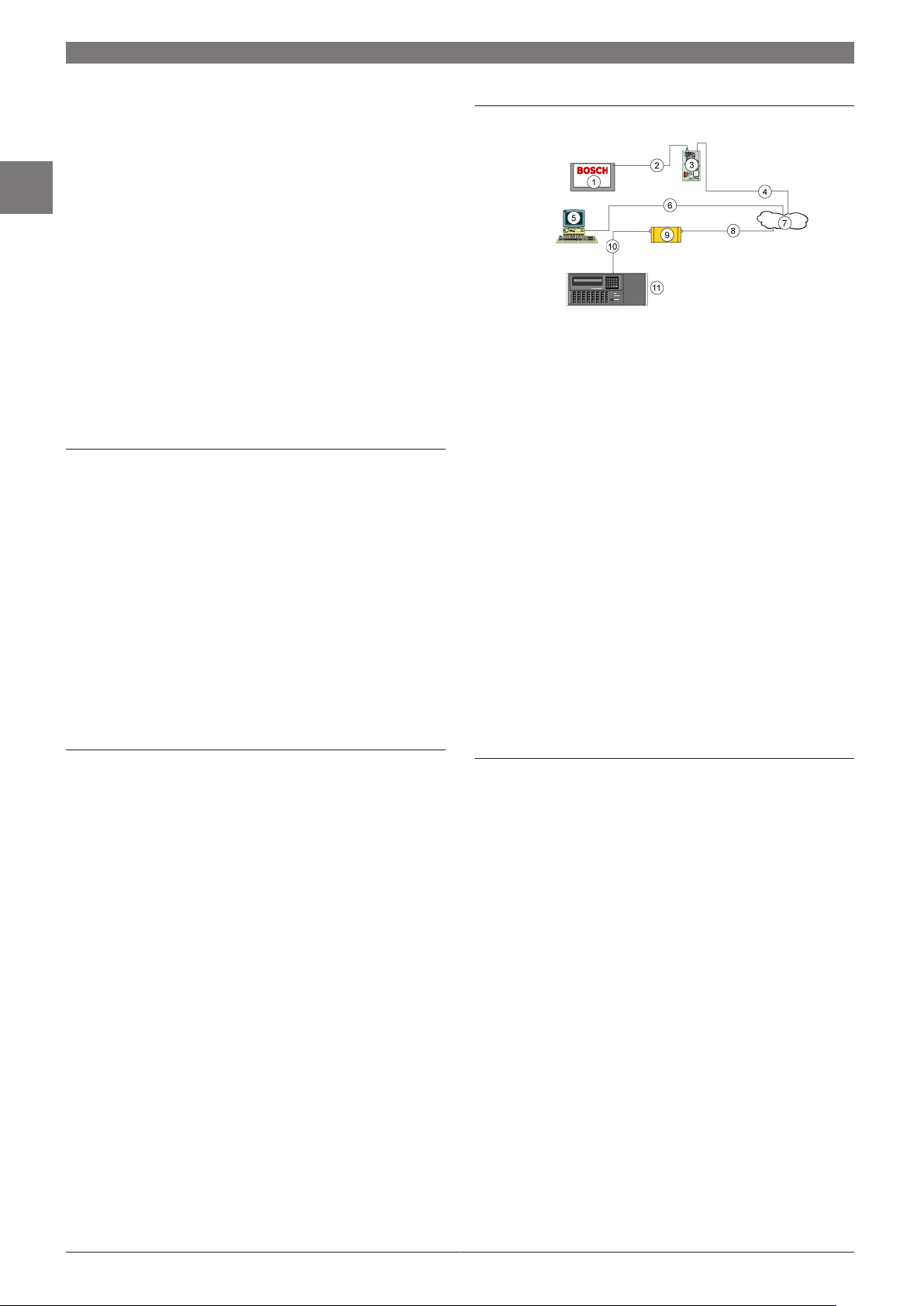
82 | Accessories for Control Panels and Keypads | Interface Modules
2
Conettix DX4020 Ethernet Network Interface Module
Features
Built-in IP-based alarm transport, programming, and
▶
control
10BASE‑T or 100BASE‑T network connection
▶
Full‑duplex and half‑duplex support
▶
Three-hole mounting pattern
▶
Support for dynamic or static IP addresses
▶
DIP switches for option bus or SDI bus address
▶
programming
Light emitting diodes (LEDs) provide control panel
▶
status
Supports 128-bit AES Rijndael encryption
▶
System Overview
1. Compatible Control Panel
2. Compatible Control Panel Option Bus or SDI Bus Connection
3. Conettix DX4020 Ethernet Network Interface Module
4. Ethernet Network Connection to DX4020
5. Host PC running Conettix D6200 Programming/Administration Software
6. Ethernet Network Connection to Host PC Ethernet Network Interface
Card (NIC)
7. Ethernet Network, Local Area Network (LAN), Metropolitan Area Network (MAN), Wide Area Network (WAN), or Internet
8. Ethernet Network Connection to Conettix D6680 Ethernet Network
Adapter
9. Conettix D6680 Ethernet Network Adapter
10. Conettix D6680 Ethernet Network Adapter Connection to Conettix
D6600 Communications Receiver/Gateway COM4 Port
11. Conettix D6600 Communications Receiver/Gateway
The system overview diagram shows a system using a
compatible control panel, Conettix DX4020 Ethernet Network
Interface Module, Conettix D6600 Communications Receiver/
Gateway, and a Conettix D6680 Ethernet Network Adapter.
The Conettix DX4020 Ethernet Network Interface Module
creates two‑way communications over Ethernet networks
for compatible control panels. Typical uses include:
Reporting to the Conettix D6600 Communications
•
Receiver/Gateway
Remote administration with Remote Programming
•
Software (RPS) or RPS‑Lite
Connecting to a PC for programming with PC9000
•
Software or Building Integration System (BIS) Security
Engine
Functions
LEDs
Red LEDs Function
BUS‑RCV Data bus receives data from control panel
BUS‑XMIT Data bus transmits data to control panel
Green LEDs Function
SER‑RX RS‑232 receives data from serial device
SER‑TX RS‑232 transmits data to serial device
Four LEDs provide information about the transmission and
receipt of data. There are also two network diagnostic LEDs
that provide information about the network connection. Refer
to the DX4020 Installation Guide (P/N 49522) for details
about the network diagnostic LED functions.
DIP Switches
Use the DIP switches to easily assign a bus address to the
DX4020.
Programmable IP Address
Use ARP and Telnet commands from any PC to program the
DX4020 IP address. The IP address can be dynamic using
DHCP or the IP address can be static.
Bosch Security Systems B.V. www.boschsecurity.com
Page 91

Accessories for Control Panels and Keypads | Interface Modules | 83
Certifications and Approvals
Region Certification
Europe CE 89/336/EEC, EN55022: 1997 +A2:
2002, EN50130-4: 1995 +A1: 1998 +A2:
2003, EN60950: 2000, EN61000-3-2:
2001, EN61000-3-3A1: 2001,
EN61000-4-2: 1995 +A1: 1998 +A2:
2001, EN61000-4-3: 1996 +A1: 1998
+A2: 2000, EN61000-4-4: 1995 +A1:
2001 +A2: 2001, EN61000-4-5: 1995
+A1: 2001, EN61000-4-6: 1996 +A1:
2000, EN61000-4-11: 1994 +A1: 2001
USA UL AMCX: Central Station Alarm Units
(UL1610, UL1635), AMCX7: Central
Station Alarm Units Certified for Canada
(cULus), APAW: Police Station Alarm Units
(UL365, UL464), APAW7: Police Station
Alarm Units Certified for Canada (cULus),
APOU: Proprietary Alarm Units (UL1076),
APOU7: Proprietary Alarm Units Certified
for Canada (cULus), NBSX7: Household
Burglar Alarm System Units Certified for
Canada (cULus), UTOU7: Control Units and
Accessories - Household System Type
Certified for Canada (cULus)
UL864, 9th edition
FM
CSFM 7167-1615: 100, 7165-1615: 119,
7170-1615: 145, and 7300-1615:
180 July 2008
NYC-MEA 12-92-E, Vol. XIII and 12-92-E, Vol. 15
France AFNOR NF, A2P Type 2 (122000076-05)
Note FM Approval applies when the DX4020 is used
with the Conettix D6600 Communications
Receiver/Gateway.
Installation/Configuration Notes
Compatibility information
Option Bus Control Panels
DS7400Xi (version 4.10 or higher)
•
CC7420‑A
•
DS7220 and DS7240 (version 2.10 or higher)
•
FPD‑7024
•
Connection Considerations
The DX4020 uses a standard Category 3 or Category 5 cable
with an RJ‑45 plug to connect to the network, a two-wire
connection from the control panel bus, and two wires that
connect to the control panel or a power supply for DC
power. For 10BASE‑T, use Category 3 or better. For
100BASE‑T, use Category 5 or better.
Mounting Considerations
The DX4020 mounts to the standard three-hole patterns in
supported control panel enclosures. With the D137
mounting bracket, the DX4020 mounts to other enclosures.
Parts Included
Quant. Component
1 Ethernet network interface module
1 Cable assembly, quick connect
1 Hardware pack
1 Literature - Installation Guide
Technical Specifications
Environmental Considerations
Dimensions: 7.6 cm x 12.7 cm (3 in. x 5 in.)
Operating Temperature: 0°C to +50°C (+32°F to +122°F)
Relative Humidity: 5% to 85% at 30°C (86°F) non‑condensing
Power Requirements
Current: 10Base‑T: 110 mA maximum
100Base‑T: 135 mA maximum
Voltage (Operating): 12 VDC nominal
2
Applications
RPS: Supported on all compatible control panels.
PC9000: Supported on the following control panels:
D9412G, D7412G, D7212G, D9112, D7412,
and D7212.
Building Integration
System (BIS) Security
Engine:
CMS 7000: Supported on DS7400Xi‑CHI Control Panels (op-
SDI Bus Control Panels (version 6.0 or higher)
D9412GV2, D7412GV2, and D7212GV2
•
D9412G, D7412G, and D7212G
•
D9412, D7412, and D7212
•
D9112
•
Supported on the following SDI bus control panels
(version 6.3 and higher): D9412GV2,
D7412GV2, D7212GV2, D9412G, D7412G, and
D7212G.
tion bus) set at Mode 18 (version 4.10 or higher).
Ordering Information
Conettix DX4020 Ethernet Network
Interface Module
Creates two‑way communications over Ethernet networks for compatible control panels.
Accessories
AE1 Standard Enclosure (Gray)
Standard gray enclosure with keyed lock.
Measures 35.6 cm x 31.8 cm x 7.6 cm (14 in.
x 12.5 in. x 3 in.).
DX4020
AE1
www.boschsecurity.com Bosch Security Systems B.V.
Page 92
84 | Accessories for Control Panels and Keypads | Interface Modules
2
Conettix C900V2 Dialer Capture Ethernet Module
Features
Captures alarm and event data from dialer-based
▶
control panels using CONTACT ID, SIA, Modem II,
Modem IIe, Modem IIIa2, Pulse, and other formats
Performs full data transmissions without changing the
▶
data
12 VDC to 24 VDC voltage range
▶
Re-routes signals using UDP/IP-based data networks
▶
Convenient connection (RJ-45 Jack) to Ethernet
▶
networks
Integrated 10/100 Network Interface Module (NIM)
▶
Provides acknowledgement from the receiver to the
▶
control panel
Supports 128-bit AES Rijndael encryption
▶
System Overview
When the dialer has a message to report, the C900V2
simulates dial tone and line voltages, causing the dialer to
behave as though it is connected to a monitoring center
digital receiver through the PSTN. The C900V2 decodes and
converts the transmitted dialer message to data for
transport over any UDP/IP network.
After the Conettix D6600 Communications Receiver/
Gateway receives a message or event, it sends an
acknowledgement message to the C900V2. The C900V2
returns an appropriate response to the dialer, maintaining
end-to-end acknowledgment.
The C900V2 operates in Intercept Mode, connecting the
dialer to the network under normal circumstances. If the
C900V2 loses contact with the Conettix D6600
Communications Receiver/Gateway, the unit goes into
Fallback Mode, connecting the dialer to the PSTN telephone
line.
The Conettix C900V2 Dialer Capture Ethernet Module
works with most control panels using a standard digital
dialer format and provides end-to-end security. The module
links the digital dialer to the Public Switched Telephone
Network (PSTN), the digital dialer’s telephone interface,
and an Ethernet network. With the Ethernet link, the
C900V2 can:
Communicate with the control panel dialer
•
Decode and deliver signals to a Conettix D6600
•
Communications Receiver/Gateway
Relay a confirmation message back to the control panel
•
dialer
Whether a control panel dials through a telephone line or
through the C900V2, the data remains the same. The
C900V2 empowers digital dialer control panels to work over
an IP network such as a Local Area Network (LAN), a Wide
Area Network (WAN), or the Internet.
Bosch Security Systems B.V. www.boschsecurity.com
1. Control Panel
2. Dialer Connection
2.1 Dialer Output to RJ-31x Jack and PSTN
3. Conettix C900V2 Dialer Capture Ethernet Module
4. Ethernet or LAN Connection
5. LAN, WAN, or the Internet
6. Connection To Ethernet Network Interface Card (NIC)
7. Host PC with Conettix D6200 Programming/Administration Software
8. Conettix D6680 Ethernet Network Adapter
9. Com 1 (Optional)
10. Com 4
11. Conettix D6600 Communications Receiver/Gateway
Page 93

Accessories for Control Panels and Keypads | Interface Modules | 85
Functions
Communication Formats
ADT-SIA
BFSK (2300Hz ACK Tone or 1400Hz ACK Tone)
DTMF (Contact ID, High Speed and 4/2 Express)
FBI Superfast DTMF (1400 Hz ACK Tone or 2300 Hz ACK Tone)
Pulse 3/1, 3/1 Checksum, 4/2 (1400 Hz ACK Tone or 2300 Hz ACK Tone)
Radionics Modem II, Radionics Modem IIe , and Modem IIIa
Seriee FSK and DTMF
SIA V.21, 110/300 baud
SIA Bell 103, 110/300 baud
Robofon
Telim
Inputs
Input Description
1 Used as an end-of-line (EOL) supervised loop. Detects open, short,
and normal states. Terminate this input with a 10 kΩ EOL resistor.
2 Used for intercept inhibit to force the C900V2 into Fallback mode
for at least two minutes.
3 Used for intercept override, allowing users to switch between in-
tercept and fallback modes.
Outputs
2
Polling and Supervision
Conettix C900V2 polling helps the Conettix D6600
Communications Receiver/Gateway to perform
supervision.
Web Programming Tool
The web programming tool makes the C900V2 configuration
process simple and convenient, similar to browsing a web site.
After obtaining an Application ID, installers can go to
www.c900v2.com from a computer with internet access and
configure the C900V2 for the preferred central station.
2
Out-
Description
put
1 Provides local annunciation if the power to the C900V2 is lost or
the CPU fails.
2 Provides local annunciation if the connection to the monitoring
center is lost.
3 Provides local annunciation whenever the C900V2 is in intercept
mode.
4 Controllable from the monitoring center and the Conettix D6200
Programming/Administration Software (default is open).
Intercept and Fallback Modes
Intercept Mode: The C900V2 connects the dialer to the
•
network. Intercept mode remains on as long as the
C900V2 remains in continuous contact with the
Conettix D6600 Communications Receiver/Gateway.
Fallback Mode: The C900V2 connects the dialer to the
•
telephone line, removing itself from the telephone
circuit. Fallback mode occurs if the C900V2 loses
contact with the Conettix D6600 Communications
Receiver/Gateway, loses power, or stops operating
correctly.
LED Indicators
The C900V2 has two dual-colored LEDs that indicate the
module's status (the SYSTEM LED and the DIALER LED).
Modular Jacks
The C900V2 module has three modular jacks.
Panel Jack: Connects to a dialer through a modular
•
telephone cord (D162).
TELCO Jack: Connects to a PSTN line through a
•
modular telephone cord (D162).
Ethernet Jack: Connects to the Ethernet data network
•
through an Ethernet cable. For 10BASE-T, the cable
must be Category 3 or better. For 100BASE-T, the cable
must be Category 5 or better.
Certifications and Approvals
Region Certification
Europe CE 1999/5/EC, EN55022: 1998,
EN50130-4: 1996 +A1: 1998 +A2: 2003,
EN60950-1: 2001, EN61000-3-2,
EN61000-3-3, EN61000-4-2: 1995 +A1:
1998, EN61000-4-3: 1995 +A1: 1998,
EN61000-4-4: 1995, EN61000-4-5:
1995, EN61000-4-6: 1996,
EN61000-4-11: 1994, TBR21: 1998
Belgium INCERT B-509-0040/a
USA UL AMCX: Central Station Alarm Units
(UL1610, UL1635), AMCX7: Central
Station Alarm Units Certified for Canada
(cULus), APAW: Police Station Alarm Units
(UL365, UL464), APAW7: Police Station
Alarm Units Certified for Canada (cULus),
APOU: Proprietary Alarm Units (UL1076),
APOU7: Proprietary Alarm Units Certified
for Canada (cULus), NBSX: Household
Burglar Alarm System Units (UL1023),
NBSX7: Household Burglar Alarm System
Units Certified for Canada (cULus), UTOU:
Control Units and Accessories - Household
System Type (UL985), UTOU7: Control
Units and Accessories - Household System
Type Certified for Canada (cULus)
UL864, 9th edition
FM
CSFM 7300-1615: 180 and 7167-1615:
223 July 2008
www.boschsecurity.com Bosch Security Systems B.V.
Page 94

86 | Accessories for Control Panels and Keypads | Interface Modules
2
Australia A-Tick
Canada IC
USA FCC Part 15 Radiated/Conducted Emissions
Note FM approval applies when the C900V2 is used
with the Conettix D6600 Communications
Receiver/Gateway.
Installation/Configuration Notes
Compatibility Information
Numerous UL Listed Fire Alarm Control Panels (FACPs)
have proven compatible with the C900V2. For a complete
list, refer to the Network Dialer Capture Module C900V2
Compatibility List (F01U010036).
Technical Specifications
Connectors
Control Panel: RJ-45 Modular Jack
Telco: RJ-45 Modular Jack
LAN/WAN: RJ-45 Modular Jack
Ethernet Cable: Unshielded twisted pair 100 m (328 ft)
For 10BASE-T, use Category 3 or better.
For 100BASE-T, use Category 5 or better.
Environmental Considerations
Ordering Information
Conettix C900V2 Dialer Capture Ethernet
Module
Compatible with control panels using a standard digital dialer format. Provides end-to-end
security. Allows digital dialer control panels to
work over an IP network (such as LAN, WAN,
or the Internet).
Accessories
AE1 Standard Enclosure (Gray)
Standard gray enclosure with keyed lock.
Measures 35.6 cm x 31.8 cm x 7.6 cm (14 in.
x 12.5 in. x 3 in.).
C900V2
AE1
Temperature (Operating): 0°C to +49°C (+32°F to +120°F)
Indicators
Module Status LEDs: 2 dual-colored
Module
Dimensions: 17.8 cm x 11.4 cm
(7 in. x 4.5 in.)
Interface: IEEE 802.3
Power Requirements
Current (Maximum): 280 mA
Voltage Range: 12 VDC to 24 VDC nominal
Alarm Outputs: Normally-open (NO) dry contacts
Protocols
Output To LAN or WAN: UDP/IP packets
Bosch Security Systems B.V. www.boschsecurity.com
Page 95

Accessories for Control Panels and Keypads | Interface Modules | 87
DX4010i RS‑232 Serial Interface Module
Features
Transparent enclosure
▶
Diagnostic light emitting diodes (LEDs)
▶
RJ-16 data bus connector
▶
DIP switches for address and bus programming
▶
Enhanced direct connection for Remote Programming
▶
Software (RPS)
DB9 DTE RS-232 connector
▶
The DX4010i RS-232 Serial Interface Module creates a local
connection between compatible control panels and
approved applications or other RS-232 devices. The module
connects to the control panel’s data bus which provides
power and data.
System Overview
2
The DX4010i RS-232 Serial Interface Module connects to:
1. A control panel’s option or serial device interface (SDI)
bus through the data bus connector.
2. A PC for RPS, BIS, or other third party applications
through the RS-232 connector.
3. A serial printer or parallel printer with a converter cable
box (not shown) through the RS-232 connector with a
compatible control panel. Refer to Compatibility
Information for details.
Functions
DIP Switches
Use the external DIP switches to easily assign an address to
the DX4010i RS-232 Serial Interface Module.
RJ-16 Data Bus Connector and DB9 DTE RS-232
Connector
Use the RJ-16 data bus connector for a remote
programming connection. Use the DB9 DTE RS-232
connector to connect to approved RS-232 devices.
Transparent enclosure
The diagnostic LEDs show through the transparent
enclosure, making troubleshooting easy and convenient.
Diagnostic LEDs
There are four diagnostic LEDs that provide information
about the transmission and receipt of data.
www.boschsecurity.com Bosch Security Systems B.V.
Page 96

88 | Accessories for Control Panels and Keypads | Interface Modules
2
Two Red LEDs Function
BUS RX Data bus receives data from control
panel
BUS TX Data bus transmits data to control
panel
Two Green LEDs Function
SER RX RS-232 receives data from serial de-
vice
SER TX RS-232 transmits data to serial device
Certifications and Approvals
Region Certification
Europe CE 89/336/EEC, EN55022: 1994 +A1: 1995
+A2: 1997 Class A, EN50130-4: 1995
+A1: 1998 +A2: 2003, EN60950-1:
2001, EN61000-3-2: 2000,
EN61000-3-3: 1995 +A1: 2001
Australia C-Tick
Installation/Configuration Notes
Compatibility Information
United States D9133 Serial In-
terface Module
D9133DC Serial
Interface Module
D9533 RS-232
Serial Interface
Module
Europe, United States, and
China
*CMS 7000 is available in China only.
DX4010 RS-232
Serial Interface
Module
For use with BIS, PC9000, or other
third party applications on SDI bus control panels.
For use with RPS or other third party
applications on SDI bus control panels.
For use with RPS, CMS 7000*, or printers on option bus control panels
For use with RPS, CMS 7000*, or printers on option bus control panels.
Technical Specifications
Environmental Considerations
Operating Temperature: 0°C to +50°C
(+32°F to +122°F)
Relative Humidity: 5% to 85% at +30°C (+86°F) non-condensing
Power Requirements
Current (Maximum): 50 mA nominal, 55 mA with LED
Voltage (Operating): 8 VDC to 14 VDC
Applications and RS-232 Devices
United
States
China CMS 7000: Supported on DS7400Xi Control Panels (op-
All Printers: Supported on option bus control panels.
SDI Bus Control Panels (version 6.0 or higher)
United
States
Option Bus Control Panels
Europe
Australia
United
States
The DX4010i RS-232 Serial Interface Module replaces the
following modules:
RPS: Supported on all compatible control panels.
PC9000: Supported on all the following control panels:
D9412G, D7412G, D7212G, D9112,
D7412, and D7212.
Building Integration Software
(BIS):
D7212G, D7412G, and D9412G
•
D7212, D7412, and D9412
•
D9112
•
DS7400Xi (version 2.02 or higher)
•
DS7220 and DS7240
•
CC7420-A
•
D4412 and D6412
•
Supported on the following SDI bus control
panels (version 6.3 and higher): D9412G,
D7412G, and D7212G.
tion bus) set at Mode 18 (version 3.09 or
higher).
Ordering Information
DX4010i RS‑232 Serial Interface Module
Locally connects compatible control panels
and approved applications or other RS-232
devices.
DX4010i
Bosch Security Systems B.V. www.boschsecurity.com
Page 97

Accessories for Control Panels and Keypads | Interface Modules | 89
DS7420i Dual Phoneline/ Bell Supervision Module
Features
One Class A input zone
▶
Two supervised 12 VDC signaling outputs
▶
Certifications and Approvals
Region Certification
Europe CE 89/336/EEC, EN55022: 1994 +A1: 1995
+A2: 1997 Class A, EN50130-4: 1995
+A1: 1998 +A2: 2003, EN60950-1:
2001, EN61000-3-2: 2000,
EN61000-3-3: 1995 +A1: 2001
1999/5/EC, EN60950 Dec 1992 (2nd
edition) +A1: 1992 +A2: 1993,
EN50081-1: 1992, EN50082-1: 1992
USA UL AMCX: Central Station Alarm Units
(UL1610, UL1635), AOTX: Local Alarm
Units (UL464, UL609), APAW: Police
Station Alarm Units (UL365, UL464),
UTOU: Control Units and Accessories Household System Type (UL985)
NYC-MEA 274-93-E, Vol. IV
USA FCC Rules, Part 15 - Class B digital device and
Part 68
Canada IC Canadian Interference‑Causing Equip-
ment Regulations - Class A digital apparatus
2
The DS7420i is an accessory board designed for use with
the DS7400Xi control panel. It allows the control to be used
in NFPA 72 installations. The DS7420i provides two
supervised 12 VDC signaling outputs, one Class A (Style D)
input zone, and dual phone line transmission and
supervision.
Functions
One Class A Input zone
The Initiating Device Circuit (Terminals 13-16) is a
Class A (Style D) loop intended for connection of normallyopen (N/O) dry contact initiating devices such as waterflow
switches.
Note The Class A loop will not support loop powered
devices such as two-wire smoke detectors.
Two Supervised 12 VDC Signaling Outputs
There are two supervised outputs:
Auxiliary Output Circuit: A 12 VDC, special application
•
supervised output that latches on alarm and resets
upon system reset. It is intended for strobes/indicating
appliances and supplies up to 1.0 A.
Indicating Appliance Circuit (Bell Output): A 12 VDC,
•
special application supervised output that supplies up
to 1.75 A for vibrating bells.
Installation/Configuration Notes
Commercial Fire Applications
For Commercial Fire applications, the TR1850 transformer
must be enclosed in the AE-TR16 Transformer Enclosure.
The wiring from the AE-TR16 to the control and the wiring
to the outlet box in conduit must also be enclosed in the AETR16 Enclosure.
Wiring
The DS7400Xi control panel must be installed in
accordance with NFPA 72 guidelines. The system is power
limited except for battery terminals. All wiring entering the
system enclosure must be power limited.
Technical Specifications
Auxiliary Power Requirements
Current (Alarm): 140 mA
Current (Supervisory): 20 mA
Voltage: 12 VDC nominal
Environmental Considerations
Temperature (Operating): 0°C to +49°C (+32° to +120°F)
Inputs Initiating Device Circuit
Max. Loop Resistance: 150 Ω total
Output (Auxiliary Output Circuit)
Current Supplied: up to 1.0 A
www.boschsecurity.com Bosch Security Systems B.V.
Page 98

2
90 | Accessories for Control Panels and Keypads | Interface Modules
Output (Indicating Appliance Circuit Bell Output)
Current Supplied: up to 1.75 A
Reference Numbers
DOC number: 1249 5895 A
FCC Registration number: ESVUSA-20294-KX-N
Load Number: 2
REN: 0.1B
Ordering Information
DS7420i Dual Phoneline/Bell Supervision
Module
Provides two supervised 12 VDC signaling outputs, one Class A (Style D) input zone, and dual
telephone line transmission.
DS7420i
Bosch Security Systems B.V. www.boschsecurity.com
Page 99

Accessories for Control Panels and Keypads | Door Access Control Modules | 91
Door Access Control Module (DACM)
2
Features
Supports up to 500 users without PC software and up
▶
to 2,000 users with PC software
Operates as an integrated security system component
▶
or as a stand-alone door controller
Works with a variety of reader types and credential
▶
formats
Users can administer the DACM from the reader
▶
keypad, security system keypad, or PC software
You can use the DACM as a stand-alone single door
controller, or integrate the DACM into a building’s security
system. Use an integrated DACM to arm and disarm the
security system. You can use credentials (cards and key
fobs), personal identification numbers (PINs), or both.
System Overview
The DACM supports the following devices separately or
combined: a proximity reader with keypad, a request-to-exit
(REX) input, a door contact.
In a system with a DACM and an integrated control panel, you
can use a credential to arm an area (partition), disarm an area
(partition), or silence an alarm.
Certifications and Approvals
Country Listings, Certifications, and Approvals
Europe, Middle East, Africa, and others
X
EN50133-1
Alarm Systems – Access Control Systems for use
in Security Applications
1. DACM Controller
2. Optional electric door strike
3. Proximity reader with keypad
4. Control panel
5. Proximity card and key fob
6. Optional door contact
7. Optional REX input
8. Desktop or laptop PC
9. Optional data transfer unit (DTU)
10. 12 VDC power supply for stand-alone systems
www.boschsecurity.com Bosch Security Systems B.V.
Page 100

92 | Accessories for Control Panels and Keypads | Door Access Control Modules
2
Installation/Configuration Notes
Compatibility Information
Control Panels
Credential Formats
Reader Types Compatibility is subject to interface and card format.
DS7240V2 and DS7220V2 Control Panels
•
DS7400Xi V4+ Control Panel firmware revision
•
4.10 or greater
Compatibility is subject to encryption type, encoding,
and format type.
Proximity ISO 50 bit
•
Wiegand 8 to 50 bit
•
Magstripe AXM
•
Proximity
•
125 KHz
•
13.56 MHz
•
Smart cards
•
Key fobs
•
HID
•
Myfare
•
Idesco
•
Indala
•
CASI-RUSCO
•
Paxton
•
Mr Access
•
Integrated Engineering
•
•
•
•
Bioscrypt
Banquetech
Deister
®
Technical Specifications
DACM
Input Power: 12 VDC
Current Draw: 65 mA
Lock Relay Rating: 5 A maximum at 12 VDC; 3 A maximum at 24 VDC
Dimensions: 87 mm x 106 mm x 30 mm
Proximity Reader with Keypad
Input Power: 12 VDC
Current Draw: 45 mA
Dimensions: 119 mm x 40 mm x 17 mm
PC Software
Processor Speed: 400 MHz minimum
Memory: 128 MB RAM minimum
Hard Drive: 100 MB free space minimum
Hardware: CD-ROM drive and serial COM port
Operating System:
Screen Resolution: 800 x 600 or 1024 x 768
Video Memory: At least 8 MB
Trademarks
Windows® 98SE, 2000, Me, XP, and Windows
®
NT
Parts Included
Components Kit 1 Kit 2 Kit 3 Kit 4 Kit 5
DACM controller X X X X X
Proximity reader with keypad X X X X
Package of 10 proximity cards X X
Package of 10 proximity key
fobs
Program card X X X X
DACM hardware pack X X X X X
Proximity reader with keypad
hardware pack
PC serial communication cable X X X
Installation guide X X X X X
PC software CD X X X X X
Kit 5 is for use with third party readers (not supplied). The
DACM supports Wiegand interfaces between 8 bit to 50 bit
(subject to format type) such as 26 bit open standard. If you
use a third party proximity reader, you can only program the
DACM from the PC and some of the enhanced LED functions
for alarm indication become unavailable.
The standard supplied proximity reader is based on 125 KHz
and supports third party cards such as EM Marin, Sokymat,
and Temic.
X X X X
X X
®
Bioscrypt
Windows® 98SE, Windows® 2000, Windows® Me, and Windows® XP are
registered trademarks of Microsoft Corporation in the United States and/or
other countries.
Windows NT® is a registered trademark of Microsoft Corporation in the United States and/or other countries.
Ordering Information
Accessories
is a registered trademark of Bioscrypt, Inc.
IUI-DACM/K1‑EX Kit 1
Standalone or PC programmable. Includes one
package of 10 proximity cards.
IUI‑DACM/K2‑EX Kit 2
Standalone only. Includes one package of 10
proximity cards.
IUI‑DACM/K3‑EX Kit 3
Standalone or PC programmable. Includes one
package of 10 proximity key fobs.
IUI‑DACM/K4‑EX Kit 4
Standalone only. Includes one package of 10
proximity key fobs.
IUI‑DACM/K5‑EX Kit 5
PC programmable only. Excludes readers and
cards.
IUI‑CNTRL/DACM Controller
For use with all DACM kits.
IUI‑DTU/DACM Data Transfer Unit (DTU)
Transfers programming information from the
computer to the controller without a direct
computer connection.
IUI‑CABLE/DACM Cable
Provides PC serial communication.
IUI-DACM/K1-EX
IUI-DACM/K2-EX
IUI-DACM/K3-EX
IUI-DACM/K4-EX
IUI-DACM/K5-EX
IUI-CNTRL/DACM
IUI-DTU/DACM
IUI-CABLE/DACM
Bosch Security Systems B.V. www.boschsecurity.com
 Loading...