

Page 1
RGB ELEKTRONIKA AGACIAK CIACIEK
SPÓŁKA JAWNA
Jana Dlugosza 2-6 Street
51-162 Wrocław
Poland
biuro@rgbelektronika.pl
+48 71 325 15 05
www.rgbautomatyka.pl
www.rgbelektronika.pl
DATASHEET
www.rgbautomatyka.pl
www.rgbelektronika.pl
OTHER SYMBOLS:
CL400
BOSCH REXROTH
Page 2
YOUR
PARTNER IN
MAINTENANCE
At our premises in Wrocław, we have a fully equipped servicing facility. Here we perform all the repair
works and test each later sold unit. Our trained employees, equipped with a wide variety of tools and
having several testing stands at their disposal, are a guarantee of the highest quality service.
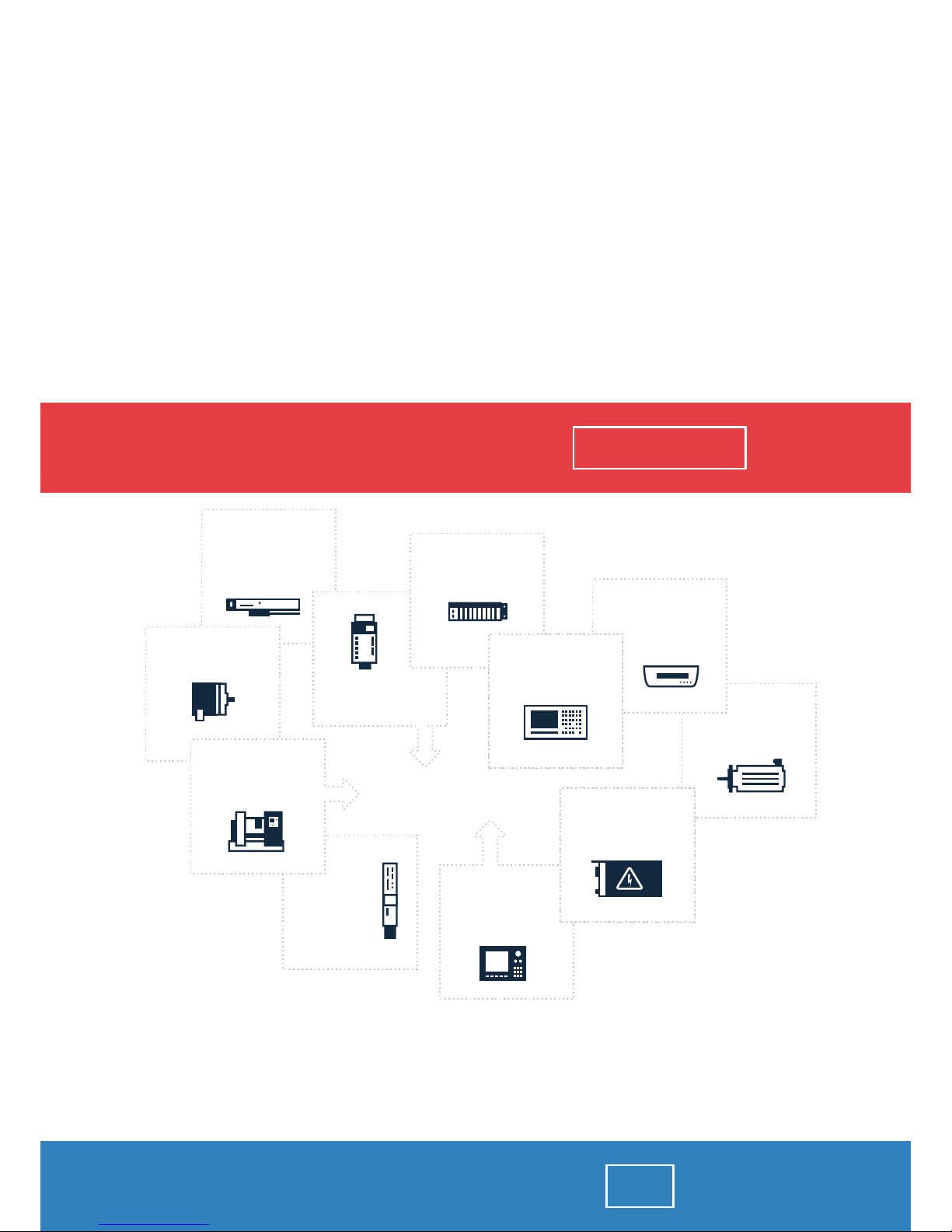
OUR SERVICES
ENCODERS
SERVO
DRIVERS
LINEAR
ENCODERS
SERVO AMPLIFIERS
CNC
MACHINES
MOTORS
POWER
SUPPLIERS
OPERATOR
PANELS
CNC
CONTROLS
INDUSTRIAL
COMPUTERS
PLC
SYSTEMS
Repair this product with RGB ELEKTRONIKA
ORDER A DIAGNOSIS
∠
Buy this product at RGB AUTOMATYKA
BUY
∠
Page 3
Automationstechnik
Antriebs- und Steuerungstechnik
CL400
Manual
CL400
101
Version
Page 4
CL400
CL400
Manual
1070 072 143-101 (95.04) GB
E 1995
by Robert Bosch GmbH,
All rights reserved, including applications for protective rights.
Reproduction or handing over to third parties are subject to our written permission.
Discretionary charge 20.– DM
Page 5
Safety instructions and reading help
V
1070 072 143-101
Safety instructions and reading help
Read this instruction manual before you use the CL400. Keep this manual in
a place where it is always accessible to all users.
Standard operation
This instruction manual contains all of the information required for standard
operation of the described products.
The products described were developed, manufactured, tested and do
cumented in accordance with the relevant safety standards. There should
be no risk of danger to personnel or property if the specifications and safety
instructions relating to the project phase and installation and correct oper
ation of the product are followed.
Qualified personnel
This instruction manual is designed for specially trained PLC personnel.
The relevant requirements are based on the job specifications as described
by the ZVEI, see:
Anforderungsprofile für SPSFachkräfte
I + K SPEKTRUM 19
Hrsg.: ZVEI
Stresemannallee 19
60596 Frankfurt
Federal Republic of Germany
ISSN 0932-5018
This instruction manual is designed for PLC engineer.
Interventions in the hardware and software of our products which are not
described in this instruction manual may only be performed by our skilled
personnel.
Unqualified interventions in the hardware or software or noncompliance
with the warnings listed in this instruction manual or indicated on the prod
uct may result in serious personal injury or damage to property.
Page 6
Safety instructions and reading help
VI
1070 072 143-101
Qualified personnel are persons who
D as planning personnel, are familiar with the safety guidelines used
in electrical engineering and automation technology.
D as operating personnel, are familiar with the equipment used in the
field of automation technology and are thus familiar with the operat
ing instructions in this manual.
D as commissioning personnel, are authorized to commission,
ground and classify electric circuits and devices/systems in accord
ance with the relevant safety standards.
Safety instructions on the control components
The following warnings and notices may be indicated on the control com
ponents themselves and have the following meaning:
Danger: High voltage!
Danger: Battery acid!
Electrostaticallysensitive components!
Disconnect at mains before opening!
Pin for connecting PE conductor only!
For screened conductor only!
Page 7
Safety instructions and reading help
VII
1070 072 143-101
Safety instructions in this manual
!
.
These symbols are used throughout this manual subject to the following
conditions.
DANGER
This symbol is used to warn of the presence of dangerous electrical cur
rent. Insufficient or lacking compliance with these instructions can result in
personal injury.
Safety instructions accompanied by this symbol are serially numbered, for
example 0.1. The appendix provides translations of the safety notes shown
here in all the official EC languages.
DANGER
This symbol is used wherever an insufficient or lacking compliance with in
structions can result in personal injury.
Safety instructions accompanied by this symbol are serially numbered, for
example 0.1. The appendix provides translations of the safety notes shown
here in all the official EC languages.
CAUTION
This symbol is used wherever an insufficient or lacking compliance with in
structions can result in damage to equipment or files.
Safety instructions accompanied by this symbol are serially numbered, for
example 0.1. The appendix provides translations of the safety notes shown
here in all the official EC languages.
.
This symbol is used to inform the user of special features.
!
Page 8
Safety instructions and reading help
VIII
1070 072 143-101
Symbols used
L
This sign shows that the manual is describing an activity which you have to
perform, e.g.:
L Insert disk 1 into the floppy disk drive.
. We would greatly appreciate any contributions to improve this manual.
If you have any suggestions, please fill out the page provided at the
end of this manual.
Page 9
Safety instructions and reading help
IX
1070 072 143-101
Safety instructions
DANGER 0.1
Danger to persons and equipment!
Test every new program before operating the system!
CAUTION 0.2
Danger to the module!
Do not insert or remove the module when the control is switched on!
This can destroy the module. Switch off or remove the power supply
module of the control, external power supply and signal voltage before
inserting or removing the module!
CAUTION 0.3
Danger to the module!
All ESD protection measures must be observed when using the mo
dule! Avoid electrostatic discharges!
Observe the following protective measures for electrostatically endan
gered modules! (EEM)!
D The employees responsible for the storage, transport and handling
must be trained in ESD protection.
D EEMs must be stored and transported in the protective packaging
specified.
D EEMs may basically only be handled at special ESD work places set
up specifically for this purpose.
D Employees, work surfaces and all devices and tools, which could
come into contact with EEMs must be same potential (e.g. earthed).
D Wear an approved earthing strap around your wrist. The grounding
bracelet must be connected via a cable with integrated 1 M7resis
tance with the work surface.
D EEMs may on no account come into contact with chargeable ob
jects, these include most plastics.
D When inserting EEMs into devices and removing them, the power
source of the device must be switched off.
. These operating instructions apply to the following versions:
ZS400:
Firmware: 101
Hardware: Daughter board version: 0
Basic PCB version: 0
!
Page 10

Safety instructions and reading help
X
1070 072 143-101
Page 11
Contents
XI1070 072 143-101
Contents
Page
1 System introduction CL400
1.1 General 1-1. . . . . . . . . . . . . . . . . . . . . . . . . . . . . . . . . . . . . . .
1.2 Configuration 1-3. . . . . . . . . . . . . . . . . . . . . . . . . . . . . . . . . .
1.3 Programming 1-5. . . . . . . . . . . . . . . . . . . . . . . . . . . . . . . . . .
1.4 General specifications 1-6. . . . . . . . . . . . . . . . . . . . . . . . . .
1.5 Slots 1-9. . . . . . . . . . . . . . . . . . . . . . . . . . . . . . . . . . . . . . . . .
2 Subracks
2.1 Subracks GG2 and GG2/K 2-1. . . . . . . . . . . . . . . . . . . . . .
2.2 Basic unit 2-4. . . . . . . . . . . . . . . . . . . . . . . . . . . . . . . . . . . . .
2.3 Subracks EG2 and EG2/K 2-6. . . . . . . . . . . . . . . . . . . . . .
2.4 Expansion unit 2-7. . . . . . . . . . . . . . . . . . . . . . . . . . . . . . . . .
2.5 Expansion configuration 2-9. . . . . . . . . . . . . . . . . . . . . . . .
2.6 Fan unit 2-12. . . . . . . . . . . . . . . . . . . . . . . . . . . . . . . . . . . . . . .
2.6.1 Installation into subracks and electrical connection 2-15.
2.6.2 Replacing the filter mats 2-19. . . . . . . . . . . . . . . . . . . . . . . .
2.7 Modules 2-21. . . . . . . . . . . . . . . . . . . . . . . . . . . . . . . . . . . . . .
3 Power supply modules 3-1. . . . . . . . . . . .
3.1 Selecting the power supply module 3-2. . . . . . . . . . . . . .
3.2 Tasks and functions 3-5. . . . . . . . . . . . . . . . . . . . . . . . . . . .
3.3 NT1 and NT2 3-9. . . . . . . . . . . . . . . . . . . . . . . . . . . . . . . . . .
3.4 NT3 and NT24 3-14. . . . . . . . . . . . . . . . . . . . . . . . . . . . . . . . .
Page 12
Contents
XII 1070 072 143-101
Page
4 Central processing unit ZS400 4-1. . . . .
4.1 Display and control elements 4-5. . . . . . . . . . . . . . . . . . . .
4.1.1 Status and rolling 4-6. . . . . . . . . . . . . . . . . . . . . . . . . . . . . .
4.1.2 Reset key, Fix LED 4-12. . . . . . . . . . . . . . . . . . . . . . . . . . . . .
4.1.3 Retention switch 4-13. . . . . . . . . . . . . . . . . . . . . . . . . . . . . . .
4.1.4 Lock output states switch 4-14. . . . . . . . . . . . . . . . . . . . . . .
4.2 Interface X31 4-15. . . . . . . . . . . . . . . . . . . . . . . . . . . . . . . . . .
4.3 Memory card 4-18. . . . . . . . . . . . . . . . . . . . . . . . . . . . . . . . . .
4.4 Operating states 4-19. . . . . . . . . . . . . . . . . . . . . . . . . . . . . . .
4.4.1 Stop 4-19. . . . . . . . . . . . . . . . . . . . . . . . . . . . . . . . . . . . . . . . . .
4.4.2 Run 4-20. . . . . . . . . . . . . . . . . . . . . . . . . . . . . . . . . . . . . . . . . .
4.4.3 Lock output states 4-20. . . . . . . . . . . . . . . . . . . . . . . . . . . . .
4.4.4 Firmware update 4-21. . . . . . . . . . . . . . . . . . . . . . . . . . . . . . .
4.4.5 Loading the PLC program from a memory card 4-22. . . .
4.4.6 Storing the PLC program on a memory card 4-24. . . . . .
4.5 Operating modes 4-26. . . . . . . . . . . . . . . . . . . . . . . . . . . . . .
4.5.1 Operation with buffer battery 4-28. . . . . . . . . . . . . . . . . . . .
4.5.2 Operation without buffer battery, with memory card 4-29
4.6 ZS400 startup 4-30. . . . . . . . . . . . . . . . . . . . . . . . . . . . . . . . .
4.7 ZS400 program execution 4-32. . . . . . . . . . . . . . . . . . . . . . .
4.8 ZS400 monitor functions 4-33. . . . . . . . . . . . . . . . . . . . . . . .
5 System modules 5-1. . . . . . . . . . . . . . . . . .
5.1 ZAT1/2, ZAT1/10, ZAT2/2 and ZAT2/10 5-3. . . . . . . . . . .
5.2 Computer interface module R500 5-4. . . . . . . . . . . . . . . .
5.3 Computer Interface Module R500P 5-5. . . . . . . . . . . . . . .
5.4 Diagnostic Module DB500 5-6. . . . . . . . . . . . . . . . . . . . . .
Page 13
Contents
XIII1070 072 143-101
Page
6 Installation
6.1 Fan unit and assembly of the subracks 6-1. . . . . . . . . . .
6.2 Electrical installation 6-4. . . . . . . . . . . . . . . . . . . . . . . . . . . .
6.3 24 V load power supplies 6-5. . . . . . . . . . . . . . . . . . . . . . .
6.4 Power input from 24 V power supply 6-6. . . . . . . . . . . . .
A Appendix
A.1 Abbreviations A-1. . . . . . . . . . . . . . . . . . . . . . . . . . . . . . . . . .
A.2 Index A-2. . . . . . . . . . . . . . . . . . . . . . . . . . . . . . . . . . . . . . . . .
A.3 Safety instructions A-8. . . . . . . . . . . . . . . . . . . . . . . . . . . . .
A.3.1 Dansk A-8. . . . . . . . . . . . . . . . . . . . . . . . . . . . . . . . . . . . . . . .
A.3.2 Deutsch A-10. . . . . . . . . . . . . . . . . . . . . . . . . . . . . . . . . . . . . .
A.3.3 %LLHNIK¼ A-12. . . . . . . . . . . . . . . . . . . . . . . . . . . . . . . . . . . . . .
A.3.4 Español A-14. . . . . . . . . . . . . . . . . . . . . . . . . . . . . . . . . . . . . . .
A.3.5 Français A-16. . . . . . . . . . . . . . . . . . . . . . . . . . . . . . . . . . . . . .
A.3.6 Italiano A-18. . . . . . . . . . . . . . . . . . . . . . . . . . . . . . . . . . . . . . .
A.3.7 Nederlands A-20. . . . . . . . . . . . . . . . . . . . . . . . . . . . . . . . . . .
A.3.8 Português A-22. . . . . . . . . . . . . . . . . . . . . . . . . . . . . . . . . . . . .
A.3.9 Suomi A-24. . . . . . . . . . . . . . . . . . . . . . . . . . . . . . . . . . . . . . . .
A.3.10 Svenska A-26. . . . . . . . . . . . . . . . . . . . . . . . . . . . . . . . . . . . . .
Page 14

Contents
XIV 1070 072 143-101
Page 15
Illustrations
I1070 072 143-101
List of illustrations
Fig. Page
1-1 CL400 1-1. . . . . . . . . . . . . . . . . . . . . . . . . . . . . . . . . . . . . . . .
1-2 CL400, basic unit 1-3. . . . . . . . . . . . . . . . . . . . . . . . . . . . . .
1-3 CL400, expansion 1-4. . . . . . . . . . . . . . . . . . . . . . . . . . . . . .
1-4 CL400, specifications 1-8. . . . . . . . . . . . . . . . . . . . . . . . . . .
1-5 Slots, system modules 1-9. . . . . . . . . . . . . . . . . . . . . . . . . .
1-6 Slots, peripheral modules 1-9. . . . . . . . . . . . . . . . . . . . . . .
2-1 GG2, dimensions 2-2. . . . . . . . . . . . . . . . . . . . . . . . . . . . . .
2-2 GG2/K, dimensions 2-3. . . . . . . . . . . . . . . . . . . . . . . . . . . .
2-3 CL400, basic unit 2-4. . . . . . . . . . . . . . . . . . . . . . . . . . . . . .
2-4 Basic unit, ordering information 2-5. . . . . . . . . . . . . . . . . .
2-5 AG/ZS, specifications 2-8. . . . . . . . . . . . . . . . . . . . . . . . . .
2-6 AG/ZS, slots 2-8. . . . . . . . . . . . . . . . . . . . . . . . . . . . . . . . . .
2-7 Expansion unit, ordering information 2-8. . . . . . . . . . . . .
2-8 Expansion Module AG/PS, ordering information 2-9. . .
2-9 CL400, expansion 2-10. . . . . . . . . . . . . . . . . . . . . . . . . . . . . .
2-10 Expansion configuration, example 2-11. . . . . . . . . . . . . . .
2-11 Fan units, specifications 2-13. . . . . . . . . . . . . . . . . . . . . . . .
2-12 Fan units, ordering information 2-14. . . . . . . . . . . . . . . . . .
2-13 Subracks, fan unit 2-15. . . . . . . . . . . . . . . . . . . . . . . . . . . . . .
2-14 Fan unit with 3 fans 2-16. . . . . . . . . . . . . . . . . . . . . . . . . . . .
2-15 Fan unit with 2 fans 2-16. . . . . . . . . . . . . . . . . . . . . . . . . . . .
2-16 Fan unit with 1 fan 2-17. . . . . . . . . . . . . . . . . . . . . . . . . . . . .
2-17 Fan unit, terminal 2-17. . . . . . . . . . . . . . . . . . . . . . . . . . . . . .
2-18 Fan unit, installation 2-18. . . . . . . . . . . . . . . . . . . . . . . . . . . .
2-19 Filter mats, ordering information 2-19. . . . . . . . . . . . . . . . .
2-20 Replacing filter mat 2-19. . . . . . . . . . . . . . . . . . . . . . . . . . . . .
2-21 Components of fan unit with two fans 2-20. . . . . . . . . . . . .
Page 16
Illustrations
II 1070 072 143-101
Fig. Page
3-1 Power supply modules NT1, NT2, NT3 and NT24 3-1. .
3-2 Current supply of the power supply modules 3-2. . . . . .
3-3 Power input internal 3-4. . . . . . . . . . . . . . . . . . . . . . . . . . . .
3-4 Buffer battery, power input of the modules 3-5. . . . . . . .
3-5 Power supply modules, specifications 3-7. . . . . . . . . . . .
3-6 Power supply modules, slots 3-8. . . . . . . . . . . . . . . . . . . .
3-7 Power supply modules, ordering information 3-8. . . . . .
3-8 NT1 and NT2, front panel 3-9. . . . . . . . . . . . . . . . . . . . . . .
3-9 NT1 and NT2, jumper setting 3-11. . . . . . . . . . . . . . . . . . . .
3-10 NT1 and NT2, buffer battery 3-12. . . . . . . . . . . . . . . . . . . . .
3-11 NT3 and NT24, front panel 3-14. . . . . . . . . . . . . . . . . . . . . .
3-12 NT3 and NT24, jumper setting 3-16. . . . . . . . . . . . . . . . . . .
3-13 NT3 and NT24, buffer battery 3-17. . . . . . . . . . . . . . . . . . . .
4-1 ZS400 4-1. . . . . . . . . . . . . . . . . . . . . . . . . . . . . . . . . . . . . . . .
4-2 ZS400, Specifications 4-3. . . . . . . . . . . . . . . . . . . . . . . . . .
4-3 ZS400, slots 4-4. . . . . . . . . . . . . . . . . . . . . . . . . . . . . . . . . . .
4-4 ZS400, ordering information 4-4. . . . . . . . . . . . . . . . . . . . .
4-5 ZS400, front panel 4-5. . . . . . . . . . . . . . . . . . . . . . . . . . . . .
4-6 Status and rolling 4-6. . . . . . . . . . . . . . . . . . . . . . . . . . . . . .
4-7 2figure 7segment status display,
operational messages 4-10. . . . . . . . . . . . . . . . . . . . . . . . . .
4-8 Reset key, Fix LED 4-12. . . . . . . . . . . . . . . . . . . . . . . . . . . . .
4-9 Retention switch 4-13. . . . . . . . . . . . . . . . . . . . . . . . . . . . . . .
4-10 Lock output states switch 4-14. . . . . . . . . . . . . . . . . . . . . . .
4-11 Interface X31 4-15. . . . . . . . . . . . . . . . . . . . . . . . . . . . . . . . . .
4-12 Connection cable K16, ordering information 4-15. . . . . . .
4-13 Dip switch S1 for X31 4-16. . . . . . . . . . . . . . . . . . . . . . . . . . .
4-14 X31, transmission format 4-17. . . . . . . . . . . . . . . . . . . . . . . .
4-15 X31, baud rate/lead length 4-17. . . . . . . . . . . . . . . . . . . . . .
4-16 X31, baud rate 4-17. . . . . . . . . . . . . . . . . . . . . . . . . . . . . . . . .
4-17 X31, control signals 4-17. . . . . . . . . . . . . . . . . . . . . . . . . . . .
Page 17
Illustrations
III1070 072 143-101
Fig. Page
4-18 Memory card 4-18. . . . . . . . . . . . . . . . . . . . . . . . . . . . . . . . . .
4-19 Error messages when loading 4-23. . . . . . . . . . . . . . . . . . .
4-20 Error messages when storing 4-25. . . . . . . . . . . . . . . . . . .
4-21 Operating modes 4-26. . . . . . . . . . . . . . . . . . . . . . . . . . . . . .
4-22 ZS400, Startup 4-30. . . . . . . . . . . . . . . . . . . . . . . . . . . . . . . .
5-1 Version 5-2. . . . . . . . . . . . . . . . . . . . . . . . . . . . . . . . . . . . . . .
5-2 System modules, slots 5-2. . . . . . . . . . . . . . . . . . . . . . . . . .
5-3 ZAT, ordering information 5-3. . . . . . . . . . . . . . . . . . . . . . .
5-4 R500, ordering information 5-4. . . . . . . . . . . . . . . . . . . . . .
5-5 R500P, ordering information 5-5. . . . . . . . . . . . . . . . . . . . .
5-6 DB500, ordering information 5-6. . . . . . . . . . . . . . . . . . . . .
6-1 Basic unit 6-1. . . . . . . . . . . . . . . . . . . . . . . . . . . . . . . . . . . . .
6-2 Possible configuration of the subracks 6-2. . . . . . . . . . . .
6-3 Subracks and fan units, examples 6-3. . . . . . . . . . . . . . .
6-4 PE terminal 6-4. . . . . . . . . . . . . . . . . . . . . . . . . . . . . . . . . . . .
6-5 24 V load power supplies, specifications 6-5. . . . . . . . . .
6-6 24 V load power supplies, ordering information 6-5. . . .
6-7 Power input from 24 V power supply 6-6. . . . . . . . . . . . .
Page 18

Illustrations
IV 1070 072 143-101
Page 19
Flexible Automation
System introduction CL400
1-1
1070 072 143-101
1 System introduction CL400
1.1 General
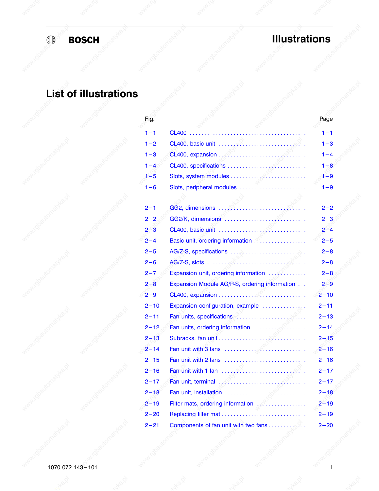
Fig. 1-1 CL400
The Bosch CL400 Programmable Logic Controller is a PLC for all control
tasks in the mid to upper power range. The CL400 is a compact monopro
cessor control unit of modular construction. With regard to peripherals and
software, it is fully compatible with the reliable CL500 multiprocessor con
trol unit. The system modules of the CL500 can also be fitted in the CL400.
Similarly, the Bosch input, output, expansion and peripheral modules are
compatible with the CL400.
Page 20
Flexible Automation
System introduction CL400
1-2
1070 072 143-101
Furthermore, the CL400 with COMNETDP represents an innovative sol
ution to the problem of decentralised installation.
COMNETDP combines the advantages of the DESI system with the bene
fits of networking via PROFIBUS. The Bosch COMNETDP is the realisation
of PROFIBUSDP and is based on DIN 19 245 part 3.
The CL400 operations set is compatible with CL500.
Memory card
The CL400 offers for the first time the possibly of operation with a memory
card in addition to operation with RAM memory and buffer battery.
Expansion capability
Possible expansions:
D central and parallel expansion units
D COMNETDP
Possible functional expansions:
D System modules
D Peripheral modules
Communication capability, interface capability
The standard interfaces
D R500
D R500P (PROFIBUSFMS)
make the CL400 capable of communicating and interfacing with
D other control systems
D computers
D standard peripheral devices
Additional functionalities
D PC modules ZAT1 and ZAT2
D Diagnostic module DB500
D Process visualisation software PV2
Peripheral modules
D Power source module SQ16
D Temperature controller module RT6
D Counter module EZ50
D Peripheral Bus Interface Module PBK
D Positioning module CC10
D Robot control system rho3.0
D Cycle time analysis module TZA
Page 21

Flexible Automation
System introduction CL400
1-3
1070 072 143-101
1.2 Configuration
Basic unit
The CL400 always consists of a basic unit first and foremost. Two subracks
are available for the basic unit,
D Subrack GG2 with 14 slots and
D Subrack GG2/K with 8 slots.
The basic unit contains
D the power supply module and
D the ZS400 central processing unit.
The remaining slots can be fitted with additional system or peripheral mod
ules.
Fig. 1-2 CL400, basic unit
If the maximum 14 basic unit slots are insufficient for control unit configur
ation, then additional peripheral modules can be fitted in expansion units.
Page 22
Flexible Automation
System introduction CL400
1-4
1070 072 143-101
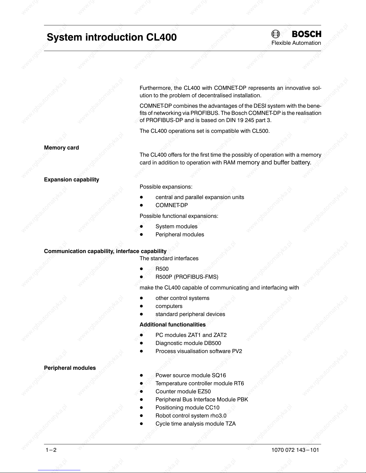
Expansion unit
Two subracks are available for the expansion unit,
D Subrack EG2 with 14 slots and
D Subrack EG2/K with 8 slots.
The expansion unit contains
D the expansion module AG/ZS and
D a maximum of 13 or 7 definable peripheral modules.
Expansion unit EG2
Basic unit GG2
NT
Fig. 1-3 CL400, expansion
. See also section 2.4 Expansion unit.
Page 23
Flexible Automation
System introduction CL400
1-5
1070 072 143-101
1.3 Programming
Programming the CL400 is carried out with Bosch programming units, an
AT compatible PC or a ZAT module.
The PLC program can be generated with the programming unit alone and
without the control unit. The PLC program is stored in a buffered RAM mem
ory in the CL400. In addition, the CL400 offers for the first time the possibility
of storing the PLC program on a memory card.
The programming language is based on DIN 19 239.
Program structure
The PLC program is divided into clear, technologically assigned program
modules.
Programming
The PLC program is created with the Bosch PLC service program. If
COMNETDP is used, the COMNETDP service program will also be re
quired.
PLC program generation can be carried out as
D IL instruction list,
D LD ladder diagram or
D SFC sequential function chart
with symbolic or absolute operands as desired.
PLC program documentation
A clear and easily comprehensible PLC program documentation with
crossreference lists support the user in fast commissioning or system fault
remedy, as well as when adapting to new applications.
The PLC program documentation on the programming unit screen and as a
printout permits a large amount of commentary.
Page 24
Flexible Automation
System introduction CL400
1-6
1070 072 143-101
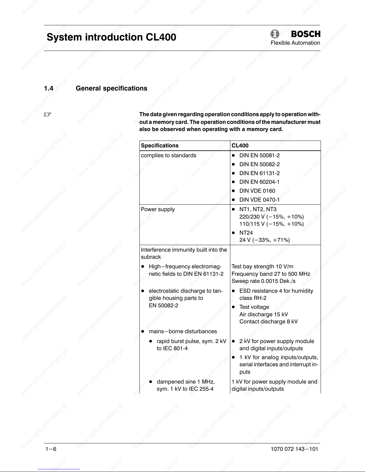
1.4 General specifications
. The data given regarding operation conditions apply to operation with
out a memory card. The operation conditions of the manufacturer must
also be observed when operating with a memory card.
Specifications
CL400
complies to standards D DIN EN 500812
D DIN EN 500822
D DIN EN 611312
D DIN EN 602041
D DIN VDE 0160
D DIN VDE 04701
Power supply D NT1, NT2, NT3
220/230 V (-15%, +10%)
110/115 V (-15%, +10%)
D NT24
24 V (-33%, +71%)
Interference immunity built into the
subrack
D High-frequency electromag
netic fields to DIN EN 611312
Test bay strength 10 V/m
Frequency band 27 to 500 MHz
Sweep rate 0.0015 Dek./s
D electrostatic discharge to tan
gible housing parts to
EN 500822
D ESD resistance 4 for humidity
class RH2
D Test voltage
Air discharge 15 kV
Contact discharge 8 kV
D mains-borne disturbances
D rapid burst pulse, sym. 2 kV
to IEC 8014
D 2 kV for power supply module
and digital inputs/outputs
D 1 kV for analog inputs/outputs,
serial interfaces and interrupt in
puts
D dampened sine 1 MHz,
sym. 1 kV to IEC 2554
1 kV for power supply module and
digital inputs/outputs
Page 25
Flexible Automation
System introduction CL400
1-7
1070 072 143-101
Specifications CL400
Interference emission
D hard emission none
D radio interference suppression
housing to DIN EN 500812
Class A
D Frequency 30 to 230 MHz limit
value 30 dB (MV/m) in 30 m
D Frequency 230 to 1000 MHz
limit value 37 dB (MV/m) in
30 m
D ZZF number no ZZF number required
Insulation test voltage
D NT1, NT2 and NT3 D for UE = 115 V
1060 V
1500 V-
D for U
E
= 230 V
1780 V
2500 V-
D all other modules 350 V
500 V-
Mechanical strength
D sinusoidal oscillations in all 3
axes to DIN EN 611312
D 10 Hz to 57 Hz
D 0.0375 mm amplitude con
stant
D 0.075 mm amplitude occa
sional
D 57 Hz to 150 Hz
D 0.5 g constant
D 1 g occasional
D impacts in all 3 axes to
DIN EN 611312
11 ms semisinusoidal 15 g
Corrosion, chemical resistance The surrounding air must be free
from high levels of acid, lye, corros
ive materials, salts, metal vapours,
or other conductive impurities.
Level of contamination to
VDE 0110 part 1
2
The immediate environment must
be free from dust. Housing and in
stallation compartments (in which
the subrack is housed) must meet
protection standard IP 54.
Page 26
Flexible Automation
System introduction CL400
1-8
1070 072 143-101
Specifications CL400
Protection standard to
DIN VDE 04701
IP 20
Protection class to VDE 0106 T1
or VDE 0160 (IEC 536)
Class Ι
Humidity class to DIN EN 611312 RH2, 5 to 95%, condensation not
permitted
Operating temperature range to
DIN EN 611312
5 to +55ºC
Storage temperature range to
DIN EN 611312
-25 to +70ºC, without battery
and memory card
Air pressure to DIN EN 61131 2 Operational to 2000 m above sea
level
Transportation stability to
DIN EN 611312
Height of fall with packaging 0.5 m
Weight
D Subrack GG2 Empty weight approx. 9 kg
Basic unit with full assembly ap
prox. 20 kg
D Subrack GG2/K Empty weight approx. 6 kg
Basic unit with full assembly ap
prox. 16 kg
D Subrack EG2 Empty weight approx. 8 kg
D Subrack EG2/K Empty weight approx. 6 kg
Dimensions in mm (W x H x D)
D Subracks GG2, EG2 19" with 14 slots
483 x 355 x 200
D Subracks GG2/K, EG2/K 11.8" with 8 slots
300 x 355 x 200
Fig. 1-4 CL400, specifications
Page 27
Flexible Automation
System introduction CL400
1-9
1070 072 143-101
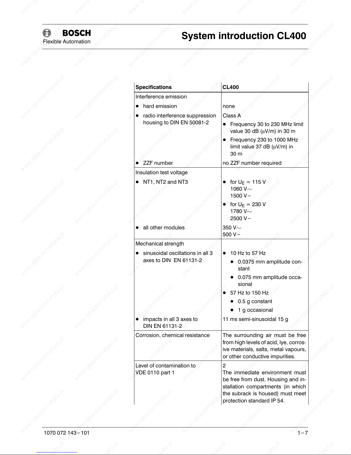
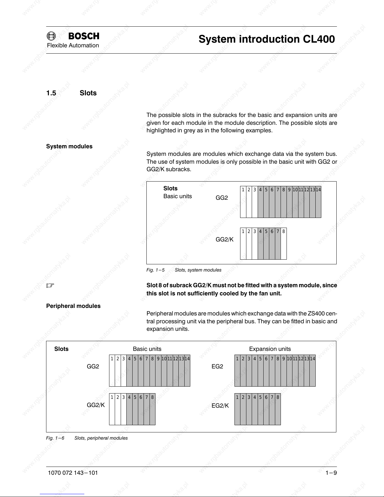
1.5 Slots
The possible slots in the subracks for the basic and expansion units are
given for each module in the module description. The possible slots are
highlighted in grey as in the following examples.
System modules
System modules are modules which exchange data via the system bus.
The use of system modules is only possible in the basic unit with GG2 or
GG2/K subracks.
GG2
1234567891011121314
Slots
Basic units
12345678
GG2/K
Fig. 1-5 Slots, system modules
. Slot 8 of subrack GG2/K must not be fitted with a system module, since
this slot is not sufficiently cooled by the fan unit.
Peripheral modules
Peripheral modules are modules which exchange data with the ZS400 cen
tral processing unit via the peripheral bus. They can be fitted in basic and
expansion units.
EG2GG2
12345678910111213141234567891011121314
Slots
EG2/K
12345678
GG2/K
12345678
Basic units Expansion units
Fig. 1-6 Slots, peripheral modules
Page 28

Flexible Automation
System introduction CL400
1-10
1070 072 143-101
Notes:
Page 29
Flexible Automation
Subracks
2-1
1070 072 143-101
2 Subracks
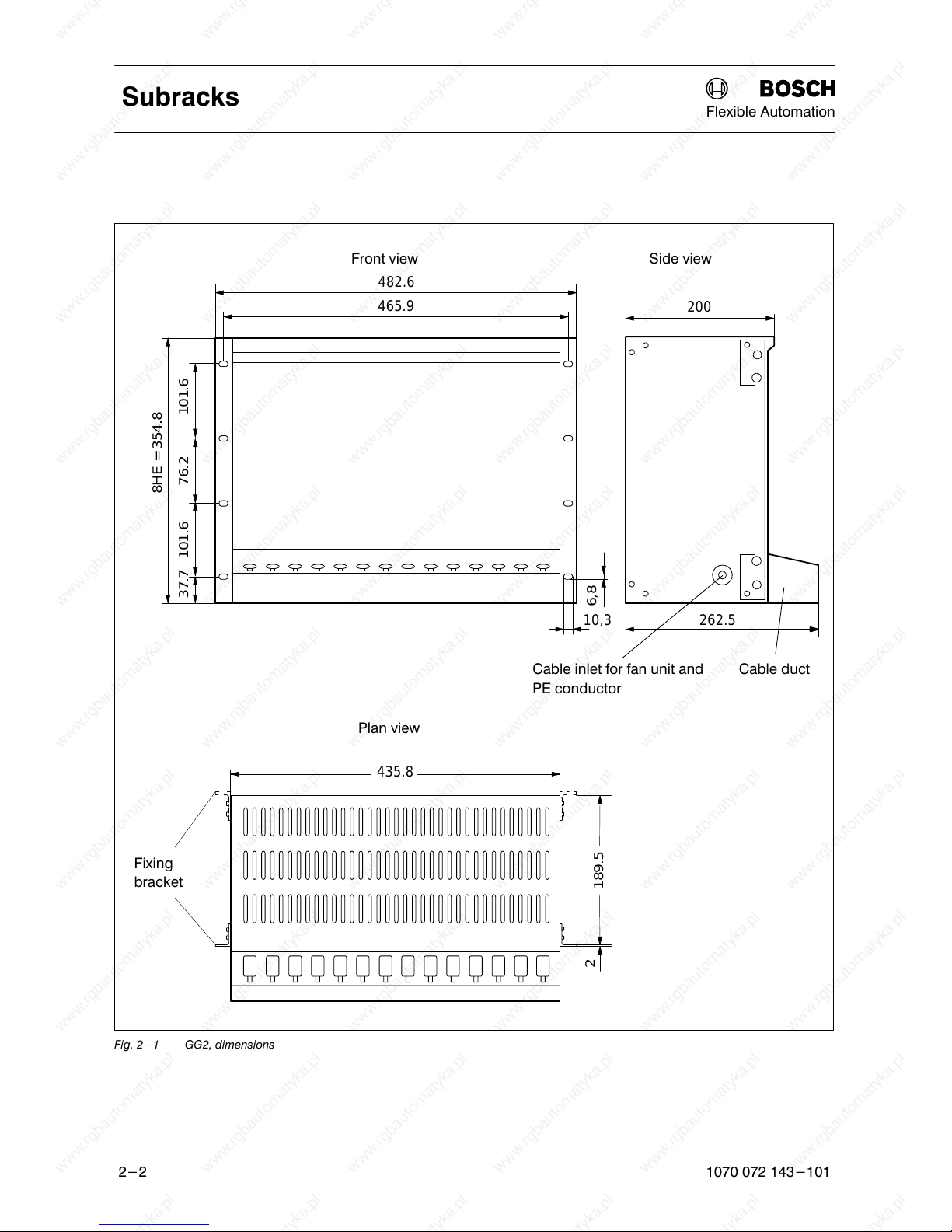
2.1 Subracks GG2 and GG2/K
Subracks GG2 and GG2/K are used for the basic unit. They consist of a 19"
or 11.8" wide metal casing with 14 or 8 slots.
A cable duct can be installed at the lower front side. This opens outwards
and makes possible the identification of the module fitted.
The subracks GG2 and GG2/K for the basic unit have two bus systems
available:
D System bus and
D Peripheral bus
. System modules must always be plugged into the basic unit.
Assembly
The subracks GG2 and GG2/K can be mounted in 19" standard switch
cabinets or fixed to vertical surfaces.
By inverting the sidemounted fixing bracket, the subracks may be
mounted on the rear as well as the front side.
. If a fan unit is used, a clearance of at least 90 mm under the subrack is
required for assembling and replacing the fan unit.
Assembly examples for various configurations of the subracks and for the
fitting of fan units may be found in section 6.1 Fan mounting and assembly
of the subracks.
Page 30
Flexible Automation
Subracks
2-2
1070 072 143-101
482.6
465.9
8HE = 354.8
101.676.2101.637.7
10,3
6,8
262.5
200
435.8
189.5
2
Front view Side view
Cable inlet for fan unit and
PE conductor
Cable duct
Plan view
Fixing
bracket
Fig. 2-1 GG2, dimensions
Page 31

Flexible Automation
Subracks
2-3
1070 072 143-101
299.8
283.1
8HE = 354.8
101.676.2101.637.7
10.3
6.8
262.5
200
253
189.5
2
Front view Side view
Cable inlet for fan unit and
PE conductor
Cable duct
Plan view
Fixing
bracket
Fig. 2-2 GG2/K, dimensions
Page 32

Flexible Automation
Subracks
2-4
1070 072 143-101
2.2 Basic unit
Fig. 2-3 CL400, basic unit
The basic unit consists of at least
D one subrack GG2 or - GG2/K,
D one cable duct,
D one fan unit,
D one power supply module NT1, NT2, NT3 or NT24 and
D one central processing unit ZS400.
. If no system modules are fitted and the power supply module NT1 or
NT24 is fitted, operation without a fan unit is possible.
The remaining 11 or 5 slots can be used if desired for
D system modules:
ZAT1 and ZAT2
R500
R500P
DB500
D peripheral modules:
Input/output modules, bus master DESIDP, temperature controller
module RT6,
D max. 3 expansion modules AG/PS
Page 33

Flexible Automation
Subracks
2-5
1070 072 143-101
PE terminal
The basic unit must be equipped with adequate connection to a PE con
ductor.
. Slot 8 of subrack GG2/K must not be fitted with a system module, since
this slot is not sufficiently cooled by the fan unit.
. Dummy slots in a subrack must be sealed with dummy covers, be
cause otherwise the air circulation will be impaired.
. The following modules must not be plugged into the basic unit:
D Expansion module AG/ZS
D RM4DP
Ordering information
Designation Order no.
Subrack GG2 1070 062 324
Subrack GG2/K 1070 075 751
Fan unit with 3 fans 1070 062 325
Fan unit with 2 fans 1070 052 243
Fan unit K with 1 fan 1070 056 864
Power supply module NT1 1070 071 376
Power supply module NT2 1070 062 687
Power supply module NT3 1070 062 309
Power supply module NT24 1070 068 046
Central processing unit ZS400 1070 070 309
Buffer battery for NT1, NT2, NT3 and NT24 1070 914 447
Cable duct CL 1070 054 152
Dummy cover 1070 046 208
Fig. 2-4 Basic unit, ordering information
Page 34

Flexible Automation
Subracks
2-6
1070 072 143-101
2.3 Subracks EG2 and EG2/K
Subracks EG2 and EG2/K are used for the expansion unit. They consist of a
19" or 11.8" wide metal casing with 14 or 8 slots.
. Information on dimensions and assembly is contained in section 2.1
Subracks GG2 and GG2/K.
Assembly examples for various configurations of the subracks and for the
fitting of fan units may be found in section 6.1 Fan mounting and assembly
of the subracks.
A cable duct can be installed at the lower front side. This opens outwards
and makes possible the identification of the module fitted.
Page 35

Flexible Automation
Subracks
2-7
1070 072 143-101
2.4 Expansion unit
. The expansion unit is used only for the attachment of peripheral mod
ules.
The expansion unit consists of at least
D one subrack EG2 or EG2/K,
D one cable duct,
D one expansion module AG/ZS and
D one connection cable AG/ZS or AG/PS.
The 13 or 7 remaining slots in the expansion unit can be fitted with periph
eral modules.
Power supply
The internal power supply of the expansion units is supplied from the power
supply module of the basic unit; for this reason the current used must be
taken into account, see section 3.1 Selecting the power supply module.
PE terminal
All expansion units must be equipped pointtopoint with adequate con
nection to a PE conductor.
. Dummy slots in a subrack must be sealed with dummy covers, be
cause otherwise the air circulation will be impaired.
. Depending on the fitting and configuration of the control unit, the in
stallation of fan units must be assessed, see section 6.1 Fan mounting
and assembly of the subracks.
Expansion module AG/ZS
The expansion module AG/ZS is used to expand the CL400 and is plugged
into the expansion unit. It supplies the internal supply voltage to the expan
sion units and the peripheral bus.
The connection is established via both socket contacts on the front panel of
the module. The two socket contacts are connected in parallel so that the
connection can be made at the upper or lower socket contact as required.
The connection between two expansion units is always established via ex
pansion module AG/ZS.
. The expansion module AG/ZS must not be plugged into the basic unit
of the CL400.
Page 36

Flexible Automation
Subracks
2-8
1070 072 143-101
Specifications
Specifications AG/ZS
Power input from 12 V internal. 10 mA
max. cable length between
D two AG/ZS
D AG/PS and AG/ZS
0.55 m
1.8 m
Width 1 division
Fig. 2-5 AG/ZS, specifications
EG2
1234567891011121314
Slots
EG2/K
12345678
Expansion units
Fig. 2-6 AG/ZS, slots
Ordering information
Description Order no.
Subrack EG2 1070 052 004
Subrack EG2/K 1070 075 760
Cable duct CL 1070 054 152
Fan unit with 2 fans 1070 052 243
Fan unit K with 1 fan 1070 056 864
Expansion module AG/ZS 1070 064 719
Connection cable AG/Z-S (K13S) 1070 064 754
Dummy cover 1070 046 208
Fig. 2-7 Expansion unit, ordering information
Page 37

Flexible Automation
Subracks
2-9
1070 072 143-101
2.5 Expansion configuration
. The maximum address range of the control unit must always be ac
counted for when carrying out an expansion.
The expansion of a CL400 using the basic unit always begins with an Ex
pansion Module AG/PS in the basic unit.
Expansion Module AG/PS
The Expansion Module AG/PS contains drivers which permit a maximum
connection cable to the Expansion Module AG/ZS of 1.8 m.
A maximum of 3 Expansion Modules AG/PS in may be operated in the
basic unit of the CL400.
. The Expansion Module AG/PS must not be plugged into the expansion
unit.
. More detailed information may be found in the manual:
Parallel Expansion Module AG/P
Module description
Ordering information
Description Order no.
Expansion Module AG/PS 1070 064 905
Connection Cable AG/PS (K14S) 1070 064 753
Parallel Expansion Module AG/P, Module description 1070 072 110
Fig. 2-8 Expansion Module AG/PS, ordering information
Page 38

Flexible Automation
Subracks
2-10
1070 072 143-101
The following are necessary for the connection between the basic unit and
an expansion unit:
D Expansion module AG/PS in the basic unit,
D Connection cable AG/PS (K14S, length 1.8 m) or connection cable
AG/ZS (K13S, length 0.55 m) and
D Expansion module AG/ZS in the expansion unit.
Expansion unit
Basic unit
EG2
NT
GG2
AG/ZS
K13S
AG/PS
Fig. 2-9 CL400, expansion
. The maximum length of the connection cable will be:
D 1.8 m between the expansion module AG/PS in the basic unit
and the module AG/ZS in the expansion unit.
D 0.55 m between two modules AG/ZS in the expansion units.
Page 39

Flexible Automation
Subracks
2-11
1070 072 143-101
The connection between two expansion units is made up of:
D Expansion module AG/ZS in 1st expansion unit.
D Connection cable AG/ZS (K13S, length 0.55 m).
D Expansion module AG/ZS in 2nd expansion unit.
AG/ZS
AG/ZS
K13S
EG2
EG2
EG2
K14S
AG/PS
AG/ZS
NT
GG2
K13-S
Fig. 2-10 Expansion configuration, example
Page 40

Flexible Automation
Subracks
2-12
1070 072 143-101
2.6 Fan unit
To avoid heat accumulation and therefore the failure or destruction of mod
ules, fan units are installed in the subracks. Three fan units are available:
D Fan unit with 3 fans for the basic unit with 14 slots.
D Fan unit with 2 fans for basic or expansion units with 14 slots.
D Fan unit K with 1 fan for basic or expansion units with 8 slots.
. A clearance of at least 90 mm beneath the subrack is necessary for the
assembly and replacement of a fan unit.
. For each module, the special information in the respective module de
scription regarding operating conditions and installation of a fan unit
must be observed.
Basic unit
Basic units may be operated without a fan unit under the following condi
tions:
D Ambient temperature in switch cabinet V45 ºC,
D Power supply module NT1 or NT24,
D No system modules and
D No peripheral modules requiring a fan unit.
The basic unit must be equipped with a fan unit if one of these conditions is
not fulfilled.
Basic units may be operated with fan units with two fans under the following
conditions:
D Ambient temperature in switch cabinet V55 ºC,
D Power supply module NT1, NT2 or NT24,
D No system module at slots 7, 8, 9, 13 and 14.
The fan unit with three fans must be used at the maximum capacity of the
basic unit.
Page 41

Flexible Automation
Subracks
2-13
1070 072 143-101
Expansion unit
In the expansion unit, the use of a fan unit is dependent on the heat dissipa
tion of the modules installed there. Always assess whether a fan unit is re
quired in the expansion unit.
Examples for various configurations of the subracks and for the fitting of fan
units may be found in section 6.1 Fan mounting and assembly of the sub
racks.
Failure contact
The fan unit has a failure contact for purposes of fault recognition, which
can be evaluated on a systemspecific basis. The following faults can be
recognised and signalled via the failure contact:
D Standstill of one or several fans.
D Falling below the 24 V supply voltage.
CAUTION 2.1
Danger to the fan unit!
Observe the maximum switching voltage and capacity for the failure
contact, see fig. 2-11 Fan units, specifications!
. With regard to the degree of contamination of the ambient air, the filter
mat of the fan unit must be regularly inspected and replaced if necess
ary, see subsection 2.6.2 Replacing the filter mats.
Specifications
Specifications
Order no. 1070 ... ...
p
062 325 052 243 056 864
Number of fans 3 2 1
Power supply 24 V- to DIN 19 240
Power input from 24 V external 1.0 A 0.8 A 0.6 A
Reverse polarity protection Fuse
M 0.1 A
via diode
Failure contact
D Switching voltage
D Switching capacity
max. 250 V-
max. 100 W
max. 60 V-, 125 V
max. 30 W, 60 VA
Response time of failure contact
when fault arises
typ. 5 s, max. 8 s
Response time of failure contact
for fault removal
5 s
Fig. 2-11 Fan units, specifications
Page 42

Flexible Automation
Subracks
2-14
1070 072 143-101
Ordering information
Description Order no.
Fan unit with 3 fans 1070 062 325
Fan unit with 2 fans 1070 052 243
Fan unit K with 1 fan 1070 056 864
Fig. 2-12 Fan units, ordering information
Page 43

Flexible Automation
Subracks
2-15
1070 072 143-101
2.6.1 Installation into subracks and electrical connection
The fan unit is installed in the lower part of the subrack.
Cable inlet for fan unit and PE con
ductor
Cable duct
Fan unit
Fig. 2-13 Subracks, fan unit
. A clearance of at least 90 mm under the subrack is required for assem
bling and replacing a fan unit.
The connection cable is fed through a bore hole in the side wall of the sub
rack. The bore hole is fitted with a rubber grommet to protect the connec
tion cable. The cable can be fed from the left or the right.
The following cables are fed through the bore hole:
D PE conductor for subrack.
D PE conductor for fan unit.
D 24 V power supply for fan unit.
D Connecting lead for failure contact.
Page 44

Flexible Automation
Subracks
2-16
1070 072 143-101
Installation and connection
L Feed connection cables through the rubber grommet.
L Connect the PE conductor for the subrack via a cable lug to the designated
pin on the subrack.
L Connect the PE conductor for the fan unit via a cable lug to the designated
pin on the fan unit.
2 4
1 pin for PE terminal
2 Bore holes for connection cable retainers
3 Terminal
4 Retainers for connection cable
31
4
Fig. 2-14 Fan unit with 3 fans
2 4
1 Pin for PE terminal
2 Bore holes for connection cable retainers
3 Terminal
4 Retainers for connection cable
31
Fig. 2-15 Fan unit with 2 fans
Page 45

Flexible Automation
Subracks
2-17
1070 072 143-101
2
1 Pin for PE terminal
2 Retainers for connection cable
3 Terminal
31
Fig. 2-16 Fan unit with 1 fan
L Connect 24 V power supply and connecting lead for failure contact accord
ing to following diagram 2-17.
CAUTION 2.2
Danger to the fan unit!
Observe the maximum switching voltage and capacity for the failure
contact, see fig. 2-11 Fan units, specifications!
1234
0 V
+24 V
Fig. 2-17 Fan unit, terminal
L Install fan unit from the bottom of the subrack with fans facing up and the
filter mat grid facing down. Firstly fit the rear edge of the fan unit to the ap
propriate subrack face.
Page 46

Flexible Automation
Subracks
2-18
1070 072 143-101
Quickrelease lock Quickrelease lock
View from below
rear edge
Fig. 2-18 Fan unit, installation
L Raise the front side of the fan unit and engage the quickrelease locks by
pushing and turning simultaneously.
Page 47

Flexible Automation
Subracks
2-19
1070 072 143-101
2.6.2 Replacing the filter mats
. With regard to the degree of contamination of the ambient air, the filter
mat of the fan unit must be inspected regularly and replaced if necess
ary.
Ordering information
Description
Order no.
Filter mat for fan unit with three fans 129 mm x 396 mm 1070 062 899
Filter mat for fan unit with two fans, 127 mm x 366 mm 1070 052 245
Filter mat for fan unit with one fan, 127 mm x 179 mm 1070 056 916
Fig. 2-19 Filter mats, ordering information
L Loosen quickrelease lock for filter mat by turning and pulling simulta
neously.
Quickrelease lock
View from below
Rear edge
Fig. 2-20 Replacing filter mat
L Fold down grid and replace filter mat.
Page 48

Flexible Automation
Subracks
2-20
1070 072 143-101
Filter mat
Grid
Quickrelease lock
Front view
Fig. 2-21 Components of fan unit with two fans
L Close grid again and engage quickrelease lock by pushing and turning
simultaneously.
. Dispose of the contaminated filter mat in accordance with the waste
disposal law regardless of the degree of contamination by the ambient
air.
Page 49

Flexible Automation
Subracks
2-21
1070 072 143-101
2.7 Modules
CAUTION 2.3
Danger to the module!
Do not insert or remove the module when the control is switched on!
This can destroy the module. Switch off or remove the power supply
module of the control, external power supply and signal voltage before
inserting or removing the module!
CAUTION 2.4
Danger to the module!
All ESD protection measures must be observed when using the mo
dule! Avoid electrostatic discharges!
A module is inserted along the rail in the subrack and fastened in place with
the two knurled screws on the front panel.
A good coupling of the module with the subrack guarantees high mechan
ical resistance and contact stability as well as increased insensitivity to ex
ternal electrical interference.
The knurled screws on the front panels must be fastened with max. 0.5 Nm.
. Dummy slots in a subrack must be covered with dummy covers, since
otherwise the air circulation will be impaired.
Page 50

Flexible Automation
Subracks
2-22
1070 072 143-101
Notes:
Page 51

Flexible Automation
Power supply modules
3-1
1070 072 143-101
3 Power supply modules
Fig. 3-1 Power supply modules NT1, NT2, NT3 and NT24
Page 52

Flexible Automation
Power supply modules
3-2
1070 072 143-101
3.1 Selecting the power supply module
The 4 power supply modules NT1, NT2, NT3 and NT24 are provided for the
internal power supply.
The selection of power supply module is made according to the configur
ation of the control. The power supply module in the basic unit is also re
sponsible for the internal power supply of all modules in the expansion
units.
To select the power supply module, some monitoring of the internal current
consumption of the modules used must be carried out.
The following table gives information on the maximum current values of the
power supply modules.
Supply voltage
Supply voltage [A]
pp y g
NT1 NT2 NT3 NT24
+5 V 4 8 26 11.2
+5 V buffer voltage 0.25 1 contained in 8 4 contained in 26 3 contained in 11.2
+12 V 1.8 3 6 4.4
+12 V ISO +0.5 +1 +4.5 +1.5
-12 V ISO -0.1 -0.5 -1.5 -1.0
Fig. 3-2 Current supply of the power supply modules
NT1
The NT1 power supply module is an inexpensive model and can be used
when no system modules can be used in the control. In this case, the basic
unit can also be operated without a fan unit; see also section 2.6 Fan units
NT2
The NT2 power supply module is an inexpensive model and can be used
when only very few modules can be used in the control.
Page 53

Flexible Automation
Power supply modules
3-3
1070 072 143-101
NT3
The NT3 power supply module is a powerful model for the maximum ca
pacity of the CL400.
The NT3 power supply module provides the 5 V and 12 V supply voltages
with a combined maximum power output of 153 W, i.e. the 5 V and 12 V sup
ply voltages may not both be loaded with their maximum current values of
26 and 6 A respectively.
NT24
The NT24 power supply module is desgined for a supply nominal voltage of
24 V-. It can be supplied via battery or rectifier.
The NT24 power supply module provides the 5 V and 12 V supply voltages
with a combined maximum power output of 99 W, i.e. the 5 V and 12 V sup
ply voltages may not both be loaded with their maximum current values of
11.2 and 4.4 A respectively.
Power input
The maximum power input of the control must be calculated when select
ing the suitable power supply module. The power inputs of the individual
modules must also be added for each supply voltage; see fig. 3-3.
Page 54

Flexible Automation
Power supply modules
3-4
1070 072 143-101
Module
max. power input in mA from
+5 V +5 V buffer volt
age
+12 V +12 V ISO -12 V ISO
ZS400
* +20 mA per active current loop
1400 150 25
70*
-10
ZAT1
* Power input of the supplementary
card
** +20 mA per active interface
2600*
150
450**
-60
ZAT2 2100 150 310 -40
R500
* +20 mA per active current loop
690 7 140* -40
R500P
* +20 mA per active current loop
1200 8 70* -20
DB500
* Colour monitor and V.24 interface
** Colour monitor and 20 mA interface
active, no control signal wiredup
1100 35
190*
250**
-20
digital input modules, per input set 0.5
E analog 150
E 10 ana 130
input module IE 24 V- 30
digital output modules, per output set 2
A analog 80
A 10 ana 100
AG/ZS 10
AG/P S 85
Bus master DESI 650
Bus master DESIDP 650
Counter module EI50 90
Positioning module CC10 120
Temperature controller module RT6 650
Peripheral buscoupling module PBK 150
Channel module MOBY ® I/F 70
Cycle time analysis module TZA 400
Fig. 3-3 Power input internal
Page 55

Flexible Automation
Power supply modules
3-5
1070 072 143-101
3.2 Tasks and functions
The power supply module takes on the following functions:
D Supply of the internal supply voltages +5V, +12V and 12V (insu
lated).
D Monitoring the input voltage for overvoltage and undervoltage.
D Monitoring the +5V and +12V for overvoltage and undervoltage.
D Monitoring the temperature of the power supply module at 60 _C
+10%.
If one of the 3 monitor functions mentioned above gives a response,
the power supply module will be switched off and all outputs will be
set to 0.
D If power failure occurs, the buffered memories of the control are sup
plied centrally from the power supply module via a buffer battery.
D Monitoring the buffer battery.
Buffer battery
The buffer battery serves the central fuse of the remanent areas for markers,
times, counters, data field and data buffer. The buffer battery takes over the
supply of the internal RAM memory of the ZS400 when the supply voltage
cuts out or the power supply module is switched off.
In connection with the Memorycard, the CL400 makes operation without
buffer battery possible.
module
max. Power input in MA at
25 _C 55 _C
NT1, NT2, NT3, NT24 60 60
ZS400 32 220
ZAT1 10 75
ZAT2 10 75
R500 10 75
R500P 15 110
DB500
D Program memory cards RAM
32 and 128 k words
D Program memory cards RAM
64 k words
10
10
20
75
75
150
Fig. 3-4 Buffer battery, power input of the modules
Page 56

Flexible Automation
Power supply modules
3-6
1070 072 143-101
The service life of the buffer battery depends
D on the fitting of the control with system modules; see fig. 3-4.
D on the ambient temperature.
D on the clearing time of the control.
. Change buffer battery after 1 year at the latest.
Monitoring the buffer battery
The monitor detects:
D absent buffer battery.
D undervoltage in the buffer battery.
Battery early warning
after
D switching on the power supply module or
D pressing the reset key on the front panel of the power supply module
a load test of the buffer battery is carried out. If an error is detected, the
special marker SM20.1 is set.
Battery failure
After a fault has been detected in the buffer battery, the ZS400 goes into op
erating status. Stop.
A battery failure is detected
D when the buffer battery monitor is switched on and the buffer battery
is absent.
D when the battery voltage is too low.
D when the ZS400 is absent or has already been withdrawn.
A detected battery failure is in addition reported on the 7segment display
of the ZS400; see fig. 4-7.
After the battery failure has been rectified, this must be acknowledged with
the reset key on the front panel of the power supply module.
Failure contact
The failure contact on the power supply module opens when:
D the internal 5 V supply voltage fails.
D ZS400 has operating status Stop
The failure contact is available to the user for systemspecific evaluation.
Page 57

Flexible Automation
Power supply modules
3-7
1070 072 143-101
Specifications NT1 NT2 NT3 NT24
Input voltage 220/230 V automatic switching 110/115 V,
-15 % to +10%, 47 to 63 Hz
24 V-,
-33% to +71%
Bonding from power inter
ruptions to the power sup
ply module
one full wave, repeat rate W 10 s to DIN EN 611312
class PS2 V10 ms,
repeat rate W 1 s
Input continuous current 1 A 1.9 A 6.9 A
Peak switching current typ. 25 A
max. 50 A
typ. 27 A
max. 50 A
typ. 23 A
max. 50 A
typ. 18 A
max. 30 A
Duration of increased cur
rent
5 ms 10 ms
Fuse M 1.6 A M 6.3 A T 6.3 A T 10 A
Supply voltages
D Buffer battery
D Logic
D Peripheral bus
D insulated for interfaces
3.6 V battery voltage
+5 V
+5 V buffer voltage
+12 V
12 V ISO
Current supply
D +5 V
D +5 V buffer voltage in
operation
D +12 V
D +12 V ISO
D -12 V ISO
4 A
0.25 A
1.8 A
+0.5 A
-0.1 A
8 A
1 A
contained in 8 A
3 A
+1 A
-0.5 A
26 A
4 A,
contained in 26 A
6 A
+4.5 A
-1.5 A
11.2 A
3 A,
contained in 11.2 A
4.4 A
1.5 A
-1 A
Buffer battery
D Capacity
D Battery voltage
D Buffer time
5.2 Ah
3.6 V
6 to 12 months
Failure contact
D Switching voltage
D Switching current
24 V-
V 2 A
Interference immunity to DIN EN 611312, VDE 0109,
VDE 0160, VDE 804, VDE 0871
IEC 8012/3/4,
DIN EN 61131-2,
VDE 0109, VDE 0160,
VDE 0871
IEC 8013/4,
DIN EN 611312,
VDE 0160
Width 2 divisions
Fig. 3-5 Power supply modules, specifications
Page 58

Flexible Automation
Power supply modules
3-8
1070 072 143-101
CAUTION 3.1
Danger to the module!
Do not insert or remove the module when the control is switched on!
This can destroy the module. Switch off or remove the power supply
module of the control, external power supply and signal voltage before
inserting or removing the module!
GG2
1234567891011121314
Slots
Basic units
12345678
GG2/K
Fig. 3-6 Power supply modules, slots
Ordering information
Designation Order no.
Power supply module NT1 1070 071 376
Power supply module NT2 1070 062 687
Power supply module NT3 1070 062 309
Power supply module NT24 1070 068 046
Buffer battery for NT1, NT2, NT3 and NT24 1070 914 447
Fig. 3-7 Power supply modules, ordering information
. The power supply modules in the basic unit do not supply the 24 V sup
ply voltage for the peripheral modules, transducers and actuators.
Power supplies for the 24 V supply voltage can be found in section 6.3
24 V load power supplies.
Page 59

Flexible Automation
Power supply modules
3-9
1070 072 143-101
3.3 NT1 and NT2
NT1
230/115 V
5/12 V
ISO 12 V
L1
N
230 / 115 V
M 1,6 A
Netz
I
O
Batterieausfall
Rücksetzen
Bereit
1 2 3 4 5
6 7 8 9
24V-/2A
LED green 5/12 V present
LED green ISO 12 V present
LED red Battery failure
Reset key, to confirm the battery failure
and for the load test of the buffer battery
Buffer battery
Failure contact
Strainrelief for the failure contact
Mains switch
Mains fuse
Mains connection
Strainrelief for the mains connection
NT2
230/115 V
5/12 V
ISO 12 V
L1
N
230 / 115 V
M6.3 A
Netz
I
O
Batterieausfall
Rücksetzen
Bereit
1 2 3 4 5
6 7 8 9
24V-/2A
Fig. 3-8 NT1 and NT2, front panel
Page 60

Flexible Automation
Power supply modules
3-10
1070 072 143-101
DANGER 3.2
Highly dangerous voltage!
Highly dangerous voltage is present at the input terminals of the power
supply modules NT1, NT2 and NT3!
Switch off the power to the terminals before working on the module!
CAUTION 3.3
Danger to the module!
Do not insert or remove the module when the control is switched on!
This can destroy the module. Switch off or remove the power supply
module of the control, external power supply and signal voltage before
inserting or removing the module!
CAUTION 3.4
Danger to the module!
All ESD protection measures must be observed when using the mo
dule! Avoid electrostatic discharges!
Page 61

Flexible Automation
Power supply modules
3-11
1070 072 143-101
Failure contact
J1
J2
3
2
1
3
2
1
Back NT2
J1
J2
3
2
1
3
2
1
Back NT1
Fig. 3-9 NT1 and NT2, jumper setting
Jumper J1
D Setting 1-2
Failure contact opens due to ZS400 operating status Stop and
power interruption
D Setting 2-3
Failure contact opens only after voltage failure; not due to ZS400 op
erating status Stop
Buffer battery
Jumper J2
D Setting 1-2
No battery operation; monitoring of the buffer battery not active
D Setting 2-3
Battery operation; monitoring of the buffer battery is active
Page 62

Flexible Automation
Power supply modules
3-12
1070 072 143-101
Installation and replacement of the buffer battery
CAUTION 3.5
Data loss!
Removing the buffer battery when the power supply module is
switched off leads to the loss of all remanent data as well as the PLC
program in the RAM memory!
Only replace the buffer battery while the power supply module is
switched on!
L Unscrew the buffer battery seal.
Seal
Buffer battery
Reset key
Fig. 3-10 NT1 and NT2, buffer battery
L Remove old buffer battery.
L Gently knock the new buffer battery on solid undersurface so that the inner
layer of oxide is destroyed.
L Insert new battery, observing the correct polarity.
L Screw in the buffer battery seal again.
A battery failure is indicated by the 7segment display showing a
. The
battery failure must be acknowledged.
Page 63

Flexible Automation
Power supply modules
3-13
1070 072 143-101
L Acknowledge the battery failure with the reset key on the front panel of the
power supply module.
At the same time, a load test of the new battery is carried out. If the 7seg
ment display of the ZS400 then still shows a
, the new battery must be
faulty.
. The old buffer battery (Lithium battery) must be fed to a special waste
disposal unit under the waste key number 35 325. The conditions of
acceptance of the waste disposal depot must be observed.
Page 64

Flexible Automation
Power supply modules
3-14
1070 072 143-101
3.4 NT3 and NT24
230/115 V
NT3
220/115 V
5/12 V
ISO 12 V
L1
N
T 6,3 A
Netz
I
O
Batterieausfall
Rücksetzen
Bereit
Batterie
24 V-/2 A
+
-
107/914447
1 2 3 4 5
6 7 8 9
LED green 5/12 V present
LED green ISO 12 V present
LED red Battery failure
Reset key, for resetting the battery fail
ure and for the load test of the new
buffer battery
Buffer battery
Failure contact
Strainrelief for the failure contact
Mains switch
Mains fuse
Mains connection
Strainrelief for the mains connection
NT24
24 V-
5/12 V
ISO 12 V
24 V
0 V
T 10 A
Netz
I
O
Batterieausfall
Rücksetzen
Bereit
Batterie
24 V-/2 A
+
-
107/914447
1 2 3 4 5
6 7 8 9
Fig. 3-11 NT3 and NT24, front panel
Page 65

Flexible Automation
Power supply modules
3-15
1070 072 143-101
DANGER 3.6
Highly dangerous voltage!
Highly dangerous voltage is present at the input terminals of the power
supply modules NT1, NT2 and NT3!
Switch off the power to the terminals before working on the module!
CAUTION 3.7
Danger to the module!
Do not insert or remove the module when the control is switched on!
This can destroy the module. Switch off or remove the power supply
module of the control, external power supply and signal voltage before
inserting or removing the module!
CAUTION 3.8
Danger to the module!
All ESD protection measures must be observed when using the mo
dule! Avoid electrostatic discharges!
NT3
The NT3 power supply module provides the 5 V and 12 V supply voltages
with a combined maximum power output of 153 W, i.e. the 5 V and 12 V sup
ply voltages may not both be loaded with their maximum current of 26 and
6 A respectively.
NT24
The NT24 power supply module provides the 5 V and 12 V supply voltages
with a combined maximum power output of 99 W, i.e. the 5 V and 12 V sup
ply voltages may not both be loaded with their maximum current of 11.2
and 4.4 A respectively.
Page 66

Flexible Automation
Power supply modules
3-16
1070 072 143-101
Failure contact
J1
J2
1
2
3
1
2
3
Back
Fig. 3-12 NT3 and NT24, jumper setting
Jumper J1
D Setting 1-2
Failure contact opens due to ZS400 operating status Stop and
power interruption
D Setting 2-3
Failure contact opens only after voltage failure; not due to ZS400 op
erating status Stop
Buffer battery
Jumper J2
D Setting 1-2
No battery operation; monitoring of the buffer battery not active
D Setting 2-3
Battery operation; monitoring of the buffer battery is active
Page 67

Flexible Automation
Power supply modules
3-17
1070 072 143-101
Installation and replacement of the buffer battery
CAUTION 3.9
Data loss!
Removing the buffer battery when the power supply module is
switched off leads to the loss of all remanent data as well as the PLC
program in the RAM memory!
Only replace the buffer battery while the power supply module is
switched on!
L Unscrew the fastening screw of the lid
Batterie
+
-
Fastening screw
Fig. 3-13 NT3 and NT24, buffer battery
L Remove lid.
L Remove buffer battery.
L Gently knock the new buffer battery on a solid undersurface so that the
inner layer of oxide is destroyed.
L Insert new battery, observing the correct polarity.
L Put the lid back on and tighten the fastening screw.
Page 68

Flexible Automation
Power supply modules
3-18
1070 072 143-101
A battery failure is indicated by the 7segment display ZS400 showing a
.
The battery failure must be acknowledged.
L Acknowledge the battery failure with the reset key on the front panel of the
power supply module.
At the same time, a load test of the new battery is carried out. If the 7seg
ment display then still shows a
, the new battery must be faulty.
. The old buffer battery (Lithium battery) must be fed to the special
waste disposal unit under the waste key number 35 325. The condi
tions of acceptance of the waste disposal depot must be observed.
Page 69

Flexible Automation
Central processing unit ZS400
4-1
1070 072 143-101
4 Central processing unit ZS400
Task
D Decoding and processing of commands in PLC program.
D Management of memory area for the data in the peripherals.
D Recognition and processing of interrupt signals.
D System monitoring
D Central system clock with calendar and alarm function
For the purposes of storing PLC programs, the central processing unit
ZS400 has an internal 256 kByte RAM memory. The PLC program is always
executed from the internal 256 kByte RAM memory.
Memory card
The central processing unit ZS400 has a plugin fixture for a memory card.
The memory card facilitates ZS400 operation without a buffer battery.
However, the PLC program being run is executed from the 256 kByte RAM
memory even when a memory card is in use and thus facilitates the use of
data modules as write/read memories. This is a major advantage of the
memory card in comparison with EPROM use up to now.
The ZS400 firmware can be loaded from a memory card.
The PLC program can be stored on a memory card or loaded from a mem
ory card.
Features
D Cyclic program execution with organisation module OM1
D Setting of system parameters in organisation module OM2
D Program startup controlled via organisation module OM5 or OM7
D Fault management in organisation module OM9
D 9 organisation modules for timers
D 8 organisation modules for interrupt inputs
D 16 organisation modules for system interrupts
D Definition of inputs/outputs
Fig. 4-1 ZS400
Page 70

Flexible Automation
Central processing unit ZS400
4-2
1070 072 143-101
D PLC program execution with monitor function
D Convenient floating point arithmetic by means of function module
D Block commands for Copy, Search and Compare
D Coordination flags
D Special marker management
D Mail boxes
D Variable cycle time monitoring
D Operations set concerning function and parameterisation compat
ible with ZS501
D Division of PLC program in two section possible, standard and sys
tem program modules
The system parameters of the ZS400 can be adapted to your requirements.
The file OB2.PCO is transferred to the directory INFO together with the PLC
service program. The system parameters can be amended in this file. This
file must be incorporated in the PLC program as organisation module OM2
in order that ZS400 recognises these amendments.
Specifications
Specifications ZS400
Program memory
D internal 256 kByte RAM buffered
D Pluggable 1 MByteMemory card, flash
EPROM or SRAM
Command execution time
D Bit command
D Word command
D Module command
<0.25 Ms
0.25 to 0.7 Ms
0.5 to 1.2 Ms
Register 4 16bit registers
Organisation modules OM 42
Program modules PM 1024
Nesting depth 62 modules
Nesting levels 7
Operand formats Bit, byte, word
Inputs
D with map
D without map
D addressable bit by bit
256 bytes, interface inputs II
256 bytes extended input EI
1024 I
Page 71

Flexible Automation
Central processing unit ZS400
4-3
1070 072 143-101
ZS400Specifications
Outputs
D with map
D without map
D addressable bit by bit
256 bytes, Interface outputs IO
256 bytes extended output EO
512 O
Marker M 2048
Timers T D 128, 10 ms time base
D 1, 1 ms time base
Counters C 128
Special markers SM 256
Data modules DM 512 per 512 bytes
Data buffer DB 512 bytes
Data field DF 24 kbyte
Mail boxes MB 8 within the data field
FIFO memory 4 x 512 byte
User stack AST 512 bytes
System range 512 bytes
Power input from
D buffer battery
D +5 V buffer voltage
D +5 V
D +12 V
D +12 V ISO
D -12 V ISO
32 MA at 25 ºC
220 MA to 55 ºC
max. 150 mA, typ. 130 mA
max. 1.4 A, typ. 0.8 A
max. 25 mA, typ. 15 mA
typ. 70 mA + 20 mA per active
current loop
typ. -10 mA
Interfaces D PCMCIA, version 2.0, type I
slot
D X31, serial V.24/20 mA inter
face, 25pin subD socket
Width 1 division
Fig. 4-2 ZS400, Specifications
Page 72

Flexible Automation
Central processing unit ZS400
4-4
1070 072 143-101
CAUTION 4.1
Danger to the module!
Do not insert or remove the module when the control is switched on!
This can destroy the module. Switch off or remove the power supply
module of the control, external power supply and signal voltage before
inserting or removing the module!
CAUTION 4.2
Danger to the module!
All ESD protection measures must be observed when using the mo
dule! Avoid electrostatic discharges!
GG2
1234567891011121314
Slots
Basic units
12345678
GG2/K
Fig. 4-3 ZS400, slots
Ordering information
Description Order no.
Central processing unit ZS400 1070 070 309
1 MB memory card, flash EPROM 1070 917 668
Fig. 4-4 ZS400, ordering information
Page 73

Flexible Automation
Central processing unit ZS400
4-5
1070 072 143-101
4.1 Display and control elements
Eject lever
LED Stop
Eject lever
Retention switch
Reset key
Lock output states switch
Rolling LED
Rolling key
2figure 7segment
status display
Stop/run switch
Plugin memory card,
PCMCIA interface
Memory card eject key
Fix LED
Interface X31
Fig. 4-5 ZS400, front panel
Page 74

Flexible Automation
Central processing unit ZS400
4-6
1070 072 143-101
4.1.1 Status and rolling
Rolling LED
Rolling key
2figure 7segment
status display
Fig. 4-6 Status and rolling
The 2figure 7segment status display, the rolling key and the rolling LED
form a display and control panel.
The 2figure 7segment status display distinguishes two displays:
D Display for Power On
D Operational messages
Power On
With Power On, the continuing initialisation of the ZS400 is accompanied
with an ascending display from
to on the lower 7segment display. When
initialisation is complete, the display
of the lower 7segment display goes
out to indicate this.
An error of initialisation is indicated by the flashing or static display of a
character between
and .
With error displays
and you may attempt to remedy the fault by starting
the firmware from a memory card. For all other error displays, the ZS400
unit must be returned to out Customer Service department.
Page 75

Flexible Automation
Central processing unit ZS400
4-7
1070 072 143-101
Operational messages
All ZS400 operational messages are 2figure.
Display
Meaning
upper lower
Operational messages of the power supply module
Communication problem between power supply
module and ZS400
Fault remedy:
Replace power supply module
Cause:
D Incorrect setting of jumper J2 at power supply
module
D Failure of buffer battery
Fault remedy:
Replace buffer battery, acknowledge with Reset
key on the front panel of the power supply module
Battery early warning
Fault remedy:
Replace buffer battery, acknowledge with Reset
key on the front panel of the power supply module
ZS400 operational messages
Memory error
Cause:
D Incorrect setting of jumper J2 at power supply
module
D Failure of buffer battery
D Error when loading the memory card
Fault remedy:
Reload PLC program and delete retentive areas
Configuration error
Cause:
Difference between the fitting of the control unit with
system modules and the SK table
Page 76

Flexible Automation
Central processing unit ZS400
4-8
1070 072 143-101
Display Meaning
upper lower
System bus error
Cause:
A system module assigns the system bus for too
long
Fault remedy:
Switch control off and on again; generally the de
fective system module must be replaced
DESI bus master not ready
Cause:
PLC stop time of the DESI bus master not yet
elapsed
Configuration error system data fields/mail boxes
Cause:
The set start addresses and lengths cause overlap
ping
Reference list error
Cause:
The assignment at the ZS400 peripheral bus with
I/O modules does not correspond with the refer
ence list in OM2.
Cycle time error
Programming error
Cause:
D Modulstack overflow,
D User stack overflow
D User stack underflow
D Data module not active
D Abort direct access
D Opcode error
Programming error
Cause:
D Parameter error
D Address error
D Range exceeded
D Module does not exist
Page 77

Flexible Automation
Central processing unit ZS400
4-9
1070 072 143-101
Display Meaning
upper lower
HOLD command
Stop request via System bus
Cause:
System bus command
Stop request via serial interface
Cause:
Programming unitsinterface X31
Stop request via Stop switch on the front panel of
the ZS400
in software version 101:
Battery failure
in software version 101:
Battery early warning
special operational displays of the ZS400
Loading the entire PLC program with data modules
from a memory card
Load RAM 0 to 128 kByte with all organisation mod
ules, the program modules 0 to 511 (system program
modules) and all data modules from a memory card
Load RAM 128 to 256 kByte with program modules
512 to 1023 (standard program modules) from a
memory card
Load the contents of the data modules from a
memory card
Store the entire PLC program with data modules on
a memory card
Store RAM 0 to 128 kByte with all organisation mod
ules, program modules 0 to 511 (system program
modules) and all data modules on a memory card
Store RAM 128 to 256 kByte with program modules
512 to 1023 (standard program modules) on a
memory card
Page 78

Flexible Automation
Central processing unit ZS400
4-10
1070 072 143-101
Display Meaning
upper lower
Store all data modules on a memory card
Version display of ZS400
Firmware version
a0b
Hardware version
a: Version of daughter board
b: Version of basic PCB
Fig. 4-7 2figure 7segment status display, operational messages
Page 79

Flexible Automation
Central processing unit ZS400
4-11
1070 072 143-101
LED rolling
The rolling LED indicates that status messages other than the one currently
displayed can be displayed using the rolling key.
Rolling key
Use the rolling key to display or select other status messages or oper
ational states.
Status messages
The status message with the highest priority is always displayed first. All
other status messages can be called up consecutively using the rolling
key.
Operating states
To display and select other operating states and to display the hard- and
firmware version, the ZS400 must be set to operating state Stop with the
Stop/Run switch, display
.
Using the rolling key, a selection can then be made between:
D
Load the PLC program from a memory card, see subsection
4.4.5
D
Store the PLC program on a memory card, see subsection
4.4.6
D
Display firmware version
D Display hardware version
Page 80

Flexible Automation
Central processing unit ZS400
4-12
1070 072 143-101
4.1.2 Reset key, Fix LED
Reset key Fix LED
Fig. 4-8 Reset key, Fix LED
The ZS400 offers you the chance to fix inputs/outputs for testing the PLC
program. The fixings are set with the PLC service program.
The LED Fix indicates when the fixings are set.
The Reset key can be used to reset all fixings.
Page 81

Flexible Automation
Central processing unit ZS400
4-13
1070 072 143-101
4.1.3 Retention switch
The ZS400 distinguishes the following modes:
D Retention
D No retention
The mode selection is made with the retention switch on the front panel of
the ZS400.
Retention switch
Fig. 4-9 Retention switch
D upper switch setting: Retention
D lower switch setting: No retention
The scope of ranges set to retentive for markers, counters, timers and data
buffers is set with the PLC service program in organisation module OM2.
The limits between retentive and nonretentive ranges set in OM2 can be
amended in the startup blocks OM5 and OM7.
. The setting of the retention switch has no effect on the data field.
Retention
ZS400 startup is performed with the retentive data of markers, counters,
timers, data buffers and fixings.
The ranges defined as nonretentive in OM2 are deleted before ZS400
startup.
. A buffer battery is required in the power supply module for retention
mode.
No retention
When restarting the ZS400 from stop mode or cold starting after switching
on the power supply module, all markers, counters, timers, fixings and data
buffers are deleted.
Page 82

Flexible Automation
Central processing unit ZS400
4-14
1070 072 143-101
4.1.4 Lock output states switch
Lock output states
switch
Fig. 4-10 Lock output states switch
The operating state Lock output states is selected using the Lock output
states switch on the front panel on the ZS400.
Behaviour of control in operating state Lock output states:
D PLC program is executed
D I/O map is executed
D All outputs are set to 0
D Buffering peripheral modules are at basic setting
D Failure contact at the power supply module is closed
. The Lock output states key is also used when storing and loading the
memory card, see subsections 4.4.5 and 4.4.6.
Page 83

Flexible Automation
Central processing unit ZS400
4-15
1070 072 143-101
4.2 Interface X31
Interface X31
Fig. 4-11 Interface X31
The programming unit is connected to the ZS400 at interface X31. The pro
tocol BUEP19E is used for data transmission, see manual:
CL400 / CL500
Übertragungsprotokolle R500
Bausteinbeschreibung
The interface has a 25pin subD socket and can be used as a V.24 or 20 mA
interface as desired by connecting the appropriate cable.
Ordering information
Description
Order no.
Connection cable K16 1070 054 956
Übertragungsprotokolle R500, Bausteinbeschreibung 1070 070 117
Fig. 4-12 Connection cable K16, ordering information
Page 84

Flexible Automation
Central processing unit ZS400
4-16
1070 072 143-101
The setting of the serial interface is carried out with dip switch S1.
CAUTION 4.3
Danger to the module!
Do not insert or remove the module when the control is switched on!
This can destroy the module. Switch off or remove the power supply
module of the control, external power supply and signal voltage before
inserting or removing the module!
CAUTION 4.4
Danger to the module!
All ESD protection measures must be observed when using the mo
dule! Avoid electrostatic discharges!
12345678
ON
OFF
S1
Fig. 4-13 Dip switch S1 for X31
Use the dip switch S1 to set the transmission format (fig. 4-14), the baud
rate (fig. 4-16) and the control signals (fig. 4-17).
Page 85

Flexible Automation
Central processing unit ZS400
4-17
1070 072 143-101
Transmission format
Switch
Function Setting
S1/1 D 1 Stop bit
D 2 stop bits
ON
OFF
S1/2 D 7 Data bits
D 8 data bits
ON
OFF
S1/3 D straight parity
D uneven parity
ON
OFF
S1/4 D parity
D no parity
ON
OFF
Fig. 4-14 X31, transmission format
Baud rate
Interface
Baud rate
[Baud]
max. Lead length
[m]
V.24 to 57600 15
20 mA to 9600
to 19200
300
150
Fig. 4-15 X31, baud rate/lead length
Baud rate
[Baud]
S1/5 S1/6 S1/7
57600 ON OFF OFF
38400 OFF OFF OFF
19200 ON ON ON
9600 OFF ON ON
4800 ON OFF ON
2400 OFF OFF ON
1200 ON ON OFF
600 OFF ON OFF
Fig. 4-16 X31, baud rate
Control signals
Switch
Function Setting
S1/8 D Query control signals
D Do not query control signals
ON
OFF
Fig. 4-17 X31, control signals
Page 86

Flexible Automation
Central processing unit ZS400
4-18
1070 072 143-101
4.3 Memory card
The ZS400 has a PCMCIA interface, version 2.0, type I slot.
The following memory cards, at least 1 MByte capacity, are supported by
the ZS400:
D S RAM card
D Intel flash memory card, series I
D AMD flash memory card, type FLKA and AFLKA
The memory card is plugged into the ZS400 with the socket connector at
the front.
The memory card replaces EPROM operation recognised by other controls
and offers possibilities only previously available with RAM operation.
. The memory card does not expand the internal PLC program memory.
Operation with the memory card is described in the following sections:
D 4.4.4 Firmware update
D 4.4.5 Loading the PLC program from a memory card
D 4.4.6 Storing the PLC program on a memory card
D 4.5 Operating modes
Write protection
switch
Fig. 4-18 Memory card
Page 87

Flexible Automation
Central processing unit ZS400
4-19
1070 072 143-101
4.4 Operating states
The ZS400 distinguishes the following operating states:
D Stop
D Run
D Lock output states
D Firmware update
D Loading a PLC program from a memory card
D Storing a PLC program on a memory card
4.4.1 Stop
Behaviour of control in operating state Stop:
D PLC program is not executed
D All outputs are set to 0
D Buffering peripheral modules are at basic setting
D Failure contact at the power supply module is open
D The STOP LED lights up on the front panel of the ZS400
D 7segment display of the ZS400 reports:
D
Stop request via system bus
D Stop request from programming unit
D Stop request via Stop/Run switch on the front panel of
the ZS400
D xy For messages of a system module with Stop request,
see relevant module description
In retention mode, the operating state Stop is retained even after failure of
the power supply.
. The Stop status can only be reset at the position where it was initiated.
Page 88

Flexible Automation
Central processing unit ZS400
4-20
1070 072 143-101
4.4.2 Run
Behaviour of control in operating state Run:
D PLC program is executed
D I/O map is executed
D Failure contact at the power supply module is closed
Switching between Stop and Run can be done via:
D System bus
D Programming unit
D Switch Stop/Run switch on the front panel of the ZS400
. The Stop status can only be reset at the position where it was initiated.
In retention mode, the operating state Run is retained even after failure of
the power supply.
4.4.3 Lock output states
The operating state Lock output states is selected using the Lock output
states switch on the front panel on the ZS400 or is selected via the pro
gramming unit.
Behaviour of control in operating state Lock output states:
D PLC program is executed
D I/O map is executed
D All outputs are set to 0
D Buffering peripheral modules are at basic setting
D Failure contact at the power supply module is closed
Page 89

Flexible Automation
Central processing unit ZS400
4-21
1070 072 143-101
4.4.4 Firmware update
This operating status is used to transfer a new firmware from a memory
card.
L Switch off control power supply module.
L Insert memory card with the new firmware in the ZS400.
L Switch on control power supply module.
The upper 7segment display of the ZS400 shows a flashing
, the Stop
and Reset Fix LEDs light up.
L Press Reset Fix key on the front panel of the ZS400.
The display at the upper 7segment display stops flashing. The new firm
ware is loaded: this takes approx. 6 to 8 seconds.
The ZS400 remains in Stop status. The lower 7segment display gives one
of the following types of information:
D
no error
D flashing content of memory card is invalid
(the old firmware is still present at the ZS400)
D flashing
ZS400 hardware error
(please consult our Customer Service depart
ment)
D flashing
new firmware not compatible with existing hard
ware
(the old firmware is still present at the ZS400)
L Remove memory card by pressing the eject key.
L Switch off control power supply module.
L Switch on control power supply module.
The ZS400 switches to operating mode No retention.
If a fault, e.g. power failure, occurs during loading, the firmware loaded to
the ZS400 will not be complete. In this case, please consult our Customer
Service department.
Page 90

Flexible Automation
Central processing unit ZS400
4-22
1070 072 143-101
4.4.5 Loading the PLC program from a memory card
Loading the PLC program from a memory card is only possible if there is no
simultaneous access from the programming unit (monitor service pro
gram) or system bus to the PLC program memory of the ZS400. The pro
cedure is then aborted with the message
on the 7segment display.
CAUTION 4.5
Data loss!
The original content of the PLC program memory of the ZS400 will be
deleted when loading the PLC program from a memory card! Check
first whether the PLC program in the ZS400 may really be deleted! If
required, save the PLC program in the ZS400 by backing up the pro
gram on an additional memory card or a programming unit.
L Switch the ZS400 to Stop with the switch on the front panel.
Red Stop LED lights up.
7segment display:
L Insert memory card into ZS400, see fig. 4-18.
L Actuate rolling key until the display
appears.
L Actuate Lock output states switch. The position of the switch is of no
consequence.
If the Lock output states switch is not actuated within 5 s, the ZS400 reverts
to Stop status.
L Actuate rolling key until the desired function is displayed on the lower
7segment display:
D
Load the entire PLC program with data modules from a memory
card.
D
Load RAM 0 to 128 kByte with all organisation modules, program
modules 0 to 511 (system program modules) and all data modules
from a memory card.
D
Load RAM 128 to 256 kByte with program modules 512 to 1023
(standard program modules) from a memory card.
Page 91

Flexible Automation
Central processing unit ZS400
4-23
1070 072 143-101
D
Load the contents of the data modules from a memory card. The
memory card must be of data modules type for this function.
The contents of all data modules are overwritten. The reference list
and the data module headers are unaffected.
D If identical data modules at the memory card and in the inter
nal RAM memory have different data module lengths, loading
will be aborted with the error message
.
D Data modules present at the memory card but not present in
the internal RAM memory are not loaded.
D Data modules not present at the memory card but present in
the internal RAM memory remain unchanged.
L Actuate Lock output states switch. The position of the switch is of no
consequence.
Loading commences.
The ZS400 reverts to Stop status when loading is complete.
Red Stop LED lights up.
7segment display:
L Switch the ZS400 back to Run with the switch on the front panel.
Error messages when loading
Display
Meaning
upper lower
Loading from the memory card could not be per
formed correctly.
The message remains on display, even when the
ZS400 is back in Run status.
The message can be deleted using the rolling key.
Fig. 4-19 Error messages when loading
Page 92

Flexible Automation
Central processing unit ZS400
4-24
1070 072 143-101
4.4.6 Storing the PLC program on a memory card
Storing the PLC program on a memory card is only possible if there is no
simultaneous access from the programming unit (monitor service pro
gram) or system bus to the PLC program memory of the ZS400. The pro
cedure is then aborted with the message
on the 7segment display.
CAUTION 4.6
Data loss!
The original content of the memory card is deleted when storing the
PLC program on a memory card! Check first whether the memory card
may really be deleted!
L Switch the ZS400 to Stop with the switch on the front panel.
Red Stop LED lights up.
7segment display:
L Insert memory card into ZS400, see fig. 4-18.
L Actuate rolling key until the display
appears.
L Actuate Lock output states switch. The position of the switch is of no
consequence.
If the Lock output states switch is not actuated within 5 s, the ZS400 reverts
to Stop status.
L Actuate rolling key until the desired function is displayed on the lower
7segment display:
D
Store the entire PLC program with data modules on a memory card
D
Store RAM 0 to 128 kByte with all organisation modules, program
modules 0 to 511 (system program modules) and all data modules
on a memory card.
D
Store RAM 128 to 256 kByte with program modules 512 to 1023
(standard program modules) on a memory card.
D
Store all data modules on a memory card.
L Actuate Lock output states switch. The position of the switch is of no
consequence.
Page 93

Flexible Automation
Central processing unit ZS400
4-25
1070 072 143-101
Storing commences.
The ZS400 reverts to Stop status when storing is complete.
Red Stop LED lights up.
7segment display:
L Switch the ZS400 back to Run with the switch on the front panel.
Error messages when storing
Display
Meaning
upper lower
Storing to the memory card could not be performed
correctly.
The message remains on display, even when the
ZS400 is back in Run status.
The message can be deleted using the rolling key.
Fig. 4-20 Error messages when storing
Page 94

Flexible Automation
Central processing unit ZS400
4-26
1070 072 143-101
4.5 Operating modes
The ZS400 distinguishes between the following operating modes which
have different effects when cold starting and restarting the control:
S114: Software switch S114 in system range
Buffer battery
Memory card Valid PLC program Retention User data memory
Yes
Buffer battery in the
power supply mod
No Cold start / Restart
Set S114 to 0000H
PLC pro
g
ram of internal
Retention Cold start / Restart
With retentive data, data
field and fixings.
pppy
ule necessary.
Jumper J2 at power
supply module in
position 2-3.
PLC program of internal
RAM memory is valid
No
retention
Cold start / Restart
Deletion of all retentive
data and fixings with ex
ception of data field
Yes
1
Cold start / Restart
Set S114 to 0001H
PLC program of memory
Retention Cold start / Restart
With retentive data, data
field and fixings
PLC program of memory
card is valid
No
retention
Cold start / Restart
Deletion of all retentive
data and fixings with ex
ception of data field
No
No buffer battery
necessary
Jumper J2 at power
supply module in
position 1-2.
Yes
Memory card
must always
be inserted.
First start
PLC program of memory
card is valid
S114 is then set to 0000H
automatically
Restart
Retention First start
Deletion of all retentive
data, data field and fixings
Restart
With retentive data, data
field and fixings
S114 must be set to 0000H
or 0001H according to the
desired restart.
No
retention
First start
Deletion of all retentive
data, data field and fixings
Restart
Deletion of all retentive
data and fixings with ex
ception of data field
1
With firmware version 101, a first start is carried out automatically from the inserted memory card
after battery failure. From firmware version 102 onwards, the battery failure must first be acknowledged using
the Reset key on the front panel of the power supply module.
Fig. 4-21 Operating modes
Page 95

Flexible Automation
Central processing unit ZS400
4-27
1070 072 143-101
First start
First start refers to the startup of the control after switching on the power
supply module, and operation without a buffer battery or after a battery fail
ure. The internal RAM memory does not contain a valid PLC program. If a
memory card is inserted, the PLC program is loaded from the memory card
to the internal RAM memory.
All retentive data, the data field and the fixings are deleted.
The software switch S114 is then set to 0000H automatically.
Cold start
Cold start refers to the startup of the control after switching on the power
supply module or after a power failure.
Restart
Restart refers to the startup of the control after a Stop/Run switchover.
Software switch S114
The software switch S114 in the system range is used to select the valid PLC
program.
D S114 = 0000H PLC program in internal RAM me
mory is valid
D S114 = 0001H PLC program on the memory card
is valid and is loaded from the me
mory card to the internal RAM me
mory
There are two ways to set the software switch S114:
D PLC program instruction, e.g. in organisation module OM1
D Command in PLC service program
This setting is only effective once for the next startup, subsequently the
software switch is automatically set to 0000H.
Retention
See subsection 4.1.3 Retention switch
Page 96

Flexible Automation
Central processing unit ZS400
4-28
1070 072 143-101
4.5.1 Operation with buffer battery
When operating with a buffer battery, a distinction is also made between
D Operation without memory card and
D Operation with memory card.
PLC program memory, retentive data, data field and fixings are buffered via
the buffer battery.
Operation without memory card
With Power On and a battery failure, ZS400 switches to Stop. The PLC pro
gram must be reloaded.
Operation with memory card
. With firmware version 101, a first start is automatically carried out from
the inserted memory card after a battery failure. From firmware version
102 onwards, the battery failure must first be acknowledged using the
Reset key on the front panel of the power supply module.
If the software switch S114 is set to 0001H in the system range and a mem
ory card is inserted, the contents of the memory card is loaded into the RAM
memory of the ZS400 in the event of a cold start and restart of the control.
The extent to which the PLC program is altered in the internal RAM memory
of the ZS400 depends on the contents of the memory card.
D Memory card contains the entire PLC program with data modules:
The entire PLC program in the internal RAM memory of the ZS400 is
overwritten.
D Memory card contains all organisation modules, the program mod
ules 0 to 511 and all data modules:
All organisation modules, the program modules 0 to 511 and all data
modules are overwritten.
D Memory card contains the program modules 512 to 1023:
The program modules 512 to 1023 are overwritten.
D Memory card contains only data modules:
The contents of all data modules are overwritten. The reference list
and the data module headers are unaffected.
D If identical data modules at the memory card and in the inter
nal RAM memory have different data module lengths, loading
will be aborted with the error message
.
Page 97

Flexible Automation
Central processing unit ZS400
4-29
1070 072 143-101
D Data modules present at the memory card but not present in
the internal RAM memory are not loaded.
D Data modules not present at the memory card but present in
the internal RAM memory remain unchanged.
If the contents of the inserted memory card cannot be used for the startup
of the ZS400, the error message
i s displayed.
If no memory card is inserted, the error message
appears. This happens
even if proper buffering is present. The PLC program must be reloaded.
4.5.2 Operation without buffer battery, with memory card
The PLC program of the memory card is loaded into the RAM memory of the
ZS400 in the event of first start.
With earlier control versions, the memory card works as an EPROM pro
gram memory card. Another advantage of the CL400 with its internal
256 kByte RAM memory and memory card is that the PLC program is ex
ecuted from the internal RAM memory when the control is running. In this
way the data modules in the control operation can be used as write/read
memory. The data modules contain the current values even in Stop operat
ing status.
If the contents of the inserted memory card cannot be used for the startup
of the ZS400, the error message
i s displayed.
If no memory card is inserted, the error message
is displayed. This
happens even if proper buffering is present. The PLC program must be re
loaded.
In the case of a first start, the data field and the fixings are also deleted.
Page 98

Flexible Automation
Central processing unit ZS400
4-30
1070 072 143-101
4.6 ZS400 startup
If the startup conditions are not fulfilled after switching on the power supply
module, the ZS400 switches to startup/stop, i.e. after switching to Run a
cold start is performed.
If a battery failure occurs in battery operation, or the ZS400 was unplugged,
no startup can take place; error message
. Startup is performed once
the battery failure is acknowledged and the PLC program is loaded.
Startup is then carried out independently of the setting of the retention
switch as a first start.
Setting Software switch S114:
D 0000H PLC program in internal RAM memory is valid
D 0001H PLC program on the memory card is valid
Yes
No
Power
On
ZS400
Stop
Battery
operation
Battery
failure
Memory card
inserted
Setting
S114
NoYe s No
Ye s
No
Ye s
Stop
Stop
First start,
Run
Startup/
stop
Ye s
No
0001H
0000H
Stop
First
start
No
Ye s
First
start
Startup/
stop
0000H
First
start
0001H
Fig. 4-22 ZS400, Startup
Page 99

Flexible Automation
Central processing unit ZS400
4-31
1070 072 143-101
Switching on the power supply module
After switching on the power supply module:
D Initialisation of the ZS400 and selftest
D Standard configuration of system parameters or adaptation accord
ing to organisation module OM2
D Resetting the peripherals
D Adaptation of the peripheral assignment according to the informa
tion in organisation module OM2
There are then two possibilities:
D With buffer battery:
Cold start
D Nonretention or retention
D With or without memory card
D With startup block OM5
D Without buffer battery:
First start
D Nonretention including data field
D Loading from the memory card
Stop/Run switch
After a Stop/Run switchover:
D Standard configuration of system parameters or adaptation accord
ing to organisation module OM2
D Resetting the peripherals
D Adaptation of the peripheral assignment according to the informa
tion in organisation module OM2
D Restart
D Nonretention or retention
D With or without memory card
D With startup block OM7
Page 100

Flexible Automation
Central processing unit ZS400
4-32
1070 072 143-101
4.7 ZS400 program execution
Execution of the PLC program
The operator can control the execution of the PLC program by employing
organisation modules (OM) as follows:
D Cyclic OM1
D Cold start, First start OM5
D Restart OM7
D In case of program error OM9
D Control via interrupt input OM10 to OM17
D Timecontrolled OM18 to OM25 and OM42
D Control via system interrupt OM26 to OM41
I/O map
Execution of the I/O map is carried out in a loop from address 0 to the end
address according to the following principle:
D Read in input byte
D Write output byte
Only those I/O addresses are called which are defined via the assign list in
OM2.
The counters for the timers are decremented parallel to the execution of the
I/O map. The accuracy of the timers is therefore determined by the cycle
time.
The interrupts are also processed during the I/O map execution.
Communication
The ZS400 operates the serial interface X31 and the system modules paral
lel to the execution of the PLC program.
 Loading...