

Page 1
RGB ELEKTRONIKA AGACIAK CIACIEK
SPÓŁKA JAWNA
Jana Dlugosza 2-6 Street
51-162 Wrocław
Poland
biuro@rgbelektronika.pl
+48 71 325 15 05
www.rgbautomatyka.pl
www.rgbelektronika.pl
DATASHEET
www.rgbautomatyka.pl
www.rgbelektronika.pl
OTHER SYMBOLS:
CL-E2-24V
CLE224V, CLE2 24V, CLE2-24V, CL E224V, CL E2 24V, CL E2-24V, CL-E224V, CL-E2 24V, CL-E2-24V
BOSCH REXROTH
Page 2
YOUR
PARTNER IN
MAINTENANCE
At our premises in Wrocław, we have a fully equipped servicing facility. Here we perform all the repair
works and test each later sold unit. Our trained employees, equipped with a wide variety of tools and
having several testing stands at their disposal, are a guarantee of the highest quality service.
OUR SERVICES
ENCODERS
SERVO
DRIVERS
LINEAR
ENCODERS
SERVO AMPLIFIERS
CNC
MACHINES
MOTORS
POWER
SUPPLIERS
OPERATOR
PANELS
CNC
CONTROLS
INDUSTRIAL
COMPUTERS
PLC
SYSTEMS
Repair this product with RGB ELEKTRONIKA
ORDER A DIAGNOSIS
∠
Buy this product at RGB AUTOMATYKA
BUY
∠
Page 3
Antriebs- und Steuerungstechnik
CL200
Manual
CL200
102
Edition
Page 4
CL200
CL200
Manual
1070 072 145-102 (01.07) GB
E 1995 – 2001
by Robert Bosch GmbH, Erbach / Germany
All rights reserved, including applications for protective rights.
Reproduction or distribution by any means subject to our prior written permission.
Discretionary charge 20.– DM
Page 5
Contents
V
1070 072 145-102 (01.07) GB
Contents
Page
1 Safety Instructions 1–1 . . . . . . . . . . . . . . . . . . . . . . . . . . . .
1.1 Intended use 1–1 . . . . . . . . . . . . . . . . . . . . . . . . . . . . . . . . . . . . . . . . . . .
1.2 Qualified personnel 1–2 . . . . . . . . . . . . . . . . . . . . . . . . . . . . . . . . . . . . .
1.3 Safety markings on components 1–3 . . . . . . . . . . . . . . . . . . . . . . . . . .
1.4 Safety instructions in this manual 1–4 . . . . . . . . . . . . . . . . . . . . . . . . .
1.5 Safety instructions for the described product 1–5 . . . . . . . . . . . . . . . .
1.6 Documentation, software release and trademarks 1–7 . . . . . . . . . . .
2 System Introduction 2–1 . . . . . . . . . . . . . . . . . . . . . . . . . .
2.1 Features and Functions 2–1 . . . . . . . . . . . . . . . . . . . . . . . . . . . . . . . . . .
2.1.1 UL-Certification 2–3 . . . . . . . . . . . . . . . . . . . . . . . . . . . . . . . . . . . . . . . . .
2.2 Programming 2–4 . . . . . . . . . . . . . . . . . . . . . . . . . . . . . . . . . . . . . . . . . .
2.3 CL200 Specifications 2–5 . . . . . . . . . . . . . . . . . . . . . . . . . . . . . . . . . . . .
2.4 Module slots 2–7 . . . . . . . . . . . . . . . . . . . . . . . . . . . . . . . . . . . . . . . . . . .
3 Module Racks 3–1 . . . . . . . . . . . . . . . . . . . . . . . . . . . . . . . .
3.1 Overview 3–1 . . . . . . . . . . . . . . . . . . . . . . . . . . . . . . . . . . . . . . . . . . . . . .
3.2 Assembly 3–2 . . . . . . . . . . . . . . . . . . . . . . . . . . . . . . . . . . . . . . . . . . . . . .
3.3 Basic Unit 3–5 . . . . . . . . . . . . . . . . . . . . . . . . . . . . . . . . . . . . . . . . . . . . .
3.4 Expansion Unit 3–6 . . . . . . . . . . . . . . . . . . . . . . . . . . . . . . . . . . . . . . . . .
3.4.1 Expansion Structure 3–8 . . . . . . . . . . . . . . . . . . . . . . . . . . . . . . . . . . . .
4 NT200 Power Supply Module 4–1 . . . . . . . . . . . . . . . . . .
4.1 Features and Functions 4–1 . . . . . . . . . . . . . . . . . . . . . . . . . . . . . . . . . .
4.2 Display and Control Elements 4–3 . . . . . . . . . . . . . . . . . . . . . . . . . . . .
4.3 Memory Backup Battery 4–5 . . . . . . . . . . . . . . . . . . . . . . . . . . . . . . . . .
4.4 Specifications 4–7 . . . . . . . . . . . . . . . . . . . . . . . . . . . . . . . . . . . . . . . . . .
5 Central Processing Unit 5–1 . . . . . . . . . . . . . . . . . . . . . . .
5.1 Features and Functions 5–1 . . . . . . . . . . . . . . . . . . . . . . . . . . . . . . . . . .
5.2 Display and Control Elements 5–5 . . . . . . . . . . . . . . . . . . . . . . . . . . . .
5.3 MemoryCard 5–9 . . . . . . . . . . . . . . . . . . . . . . . . . . . . . . . . . . . . . . . . . . .
5.4 Interfaces 5–10 . . . . . . . . . . . . . . . . . . . . . . . . . . . . . . . . . . . . . . . . . . . . . .
5.4.1 Interface Connections 5–10 . . . . . . . . . . . . . . . . . . . . . . . . . . . . . . . . . . .
5.4.2 X71 Interrupt and High-speed Counter Inputs 5–11 . . . . . . . . . . . . . . .
5.4.3 X72 Analog Inputs and Outputs 5–15 . . . . . . . . . . . . . . . . . . . . . . . . . . .
5.4.4 X31 Interface for PG Programming Unit 5–19 . . . . . . . . . . . . . . . . . . . .
5.4.5 X32 Second Serial Interface 5–22 . . . . . . . . . . . . . . . . . . . . . . . . . . . . . .
5.4.6 X73 PROFIBUS-DP Interface 5–24 . . . . . . . . . . . . . . . . . . . . . . . . . . . .
5.5 Operating modes 5–27 . . . . . . . . . . . . . . . . . . . . . . . . . . . . . . . . . . . . . . .
5.6 Reloading the Firmware 5–28 . . . . . . . . . . . . . . . . . . . . . . . . . . . . . . . . .
5.7 Specifications 5–29 . . . . . . . . . . . . . . . . . . . . . . . . . . . . . . . . . . . . . . . . . .
6 E 24 V– Digital Input Modules 6–1 . . . . . . . . . . . . . . . . . .
6.1 Features and Functions 6–1 . . . . . . . . . . . . . . . . . . . . . . . . . . . . . . . . . .
6.2 Connection 6–3 . . . . . . . . . . . . . . . . . . . . . . . . . . . . . . . . . . . . . . . . . . . .
6.3 Specifications 6–5 . . . . . . . . . . . . . . . . . . . . . . . . . . . . . . . . . . . . . . . . . .
Page 6
Contents
VI
1070 072 145-102 (01.07) GB
7 Digital Output Modules 7–1 . . . . . . . . . . . . . . . . . . . . . . . .
7.1 Features and Functions 7–1 . . . . . . . . . . . . . . . . . . . . . . . . . . . . . . . . . .
7.2 Connections and Settings 7–2 . . . . . . . . . . . . . . . . . . . . . . . . . . . . . . . .
7.3 A 24 V– Output Module / 0.5 A (16-way and 32-way) 7–5 . . . . . . . . .
7.4 A 24 V– / 2 A Output Module 7–7 . . . . . . . . . . . . . . . . . . . . . . . . . . . . .
7.5 AR/2A Relay Output module 7–7 . . . . . . . . . . . . . . . . . . . . . . . . . . . . . .
7.6 Specifications 7–10 . . . . . . . . . . . . . . . . . . . . . . . . . . . . . . . . . . . . . . . . . .
8 Digital Input/Output Modules 8–1 . . . . . . . . . . . . . . . . . .
8.1 Functions and Features 8–1 . . . . . . . . . . . . . . . . . . . . . . . . . . . . . . . . . .
8.2 Addressing 8–3 . . . . . . . . . . . . . . . . . . . . . . . . . . . . . . . . . . . . . . . . . . . .
8.3 Connection 8–4 . . . . . . . . . . . . . . . . . . . . . . . . . . . . . . . . . . . . . . . . . . . .
8.3.1 X10 Power Terminals 8–4 . . . . . . . . . . . . . . . . . . . . . . . . . . . . . . . . . . . .
8.3.2 X21A, X22A Inputs 8–4 . . . . . . . . . . . . . . . . . . . . . . . . . . . . . . . . . . . . . .
8.3.3 X11B, X12B Outputs 8–6 . . . . . . . . . . . . . . . . . . . . . . . . . . . . . . . . . . . .
8.4 Specifications 8–8 . . . . . . . . . . . . . . . . . . . . . . . . . . . . . . . . . . . . . . . . . .
9 DP-EA4 Peripheral Bus Station Module 9–1 . . . . . . . . .
9.1 Features and Functions 9–1 . . . . . . . . . . . . . . . . . . . . . . . . . . . . . . . . . .
9.2 Display and Control Elements, Connections and Settings 9–3 . . . . .
9.3 Specifications 9–5 . . . . . . . . . . . . . . . . . . . . . . . . . . . . . . . . . . . . . . . . . .
10 AG/S Expansion Module 10–1 . . . . . . . . . . . . . . . . . . . . . . .
10.1 Features and Functions 10–1 . . . . . . . . . . . . . . . . . . . . . . . . . . . . . . . . . .
10.2 Specifications 10–3 . . . . . . . . . . . . . . . . . . . . . . . . . . . . . . . . . . . . . . . . . .
11 R200, R200P, COM2-E Communication Modules 11–1 .
11.1 Functions and Features 11–1 . . . . . . . . . . . . . . . . . . . . . . . . . . . . . . . . . .
1 1.1.1 R200 Communication Module 11–2 . . . . . . . . . . . . . . . . . . . . . . . . . . . .
1 1.1.2 R200P Communication Module 11–3 . . . . . . . . . . . . . . . . . . . . . . . . . . .
1 1.1.3 COM2-E Communication Module 1 1–4 . . . . . . . . . . . . . . . . . . . . . . . . .
11.2 Specifications 11–6 . . . . . . . . . . . . . . . . . . . . . . . . . . . . . . . . . . . . . . . . . .
11.3 Advanced Documentation 11–7 . . . . . . . . . . . . . . . . . . . . . . . . . . . . . . . .
12 Analog Input Modules 12–1 . . . . . . . . . . . . . . . . . . . . . . . . .
12.1 Features and Functions 12–1 . . . . . . . . . . . . . . . . . . . . . . . . . . . . . . . . . .
12.1.1 E ana Analog Input Module 12–2 . . . . . . . . . . . . . . . . . . . . . . . . . . . . . . .
12.1.2 E20 ana Analog Input Module 12–3 . . . . . . . . . . . . . . . . . . . . . . . . . . . .
12.2 Specifications 12–3 . . . . . . . . . . . . . . . . . . . . . . . . . . . . . . . . . . . . . . . . . .
12.3 Advanced Documentation 12–4 . . . . . . . . . . . . . . . . . . . . . . . . . . . . . . . .
13 Analog Output Modules 13–1 . . . . . . . . . . . . . . . . . . . . . . .
13.1 Features and Functions 13–1 . . . . . . . . . . . . . . . . . . . . . . . . . . . . . . . . . .
13.1.1 A ana Analog Output Module 13–2 . . . . . . . . . . . . . . . . . . . . . . . . . . . . .
13.1.2 A10 ana Analog Output Module 13–2 . . . . . . . . . . . . . . . . . . . . . . . . . . .
13.1.3 A20 ana Analog Output Module 13–2 . . . . . . . . . . . . . . . . . . . . . . . . . . .
13.2 Specifications 13–3 . . . . . . . . . . . . . . . . . . . . . . . . . . . . . . . . . . . . . . . . . .
13.3 Advanced Documentation 13–4 . . . . . . . . . . . . . . . . . . . . . . . . . . . . . . . .
Page 7
Contents
VII
1070 072 145-102 (01.07) GB
14 Positioning Modules 14–1 . . . . . . . . . . . . . . . . . . . . . . . . . .
14.1 Features and Function 14–1 . . . . . . . . . . . . . . . . . . . . . . . . . . . . . . . . . . .
14.1.1 POS-SA1 and POS-SA2 counting / positioning modules 14–2 . . . . . .
14.1.2 POS-LR1 and POS-LR2 positioning modules 14–3 . . . . . . . . . . . . . . .
14.2 Specifications 14–4 . . . . . . . . . . . . . . . . . . . . . . . . . . . . . . . . . . . . . . . . . .
14.3 Advanced Documentation 14–4 . . . . . . . . . . . . . . . . . . . . . . . . . . . . . . . .
15 BM2-ASI Bus Master 15–1 . . . . . . . . . . . . . . . . . . . . . . . . . .
15.1 Features and Functions 15–1 . . . . . . . . . . . . . . . . . . . . . . . . . . . . . . . . . .
15.2 Specifications 15–2 . . . . . . . . . . . . . . . . . . . . . . . . . . . . . . . . . . . . . . . . . .
15.3 Advanced Documentation 15–2 . . . . . . . . . . . . . . . . . . . . . . . . . . . . . . . .
16 RM2-DP12 Module 16–1 . . . . . . . . . . . . . . . . . . . . . . . . . . . .
16.1 Features and Functions 16–1 . . . . . . . . . . . . . . . . . . . . . . . . . . . . . . . . . .
16.2 Connecting to PROFIBUS-DP 16–2 . . . . . . . . . . . . . . . . . . . . . . . . . . . .
16.3 Display and Control Elements 16–3 . . . . . . . . . . . . . . . . . . . . . . . . . . . .
16.4 Specifications 16–4 . . . . . . . . . . . . . . . . . . . . . . . . . . . . . . . . . . . . . . . . . .
16.5 Advanced Documentation 16–4 . . . . . . . . . . . . . . . . . . . . . . . . . . . . . . . .
17 Installation 17–1 . . . . . . . . . . . . . . . . . . . . . . . . . . . . . . . . . . .
17.1 External Power Supply 17–1 . . . . . . . . . . . . . . . . . . . . . . . . . . . . . . . . . .
17.2 24 V Power Supply 17–2 . . . . . . . . . . . . . . . . . . . . . . . . . . . . . . . . . . . . . .
17.2.1 Hardware Configuration w/o Electrical Isolation 17–2 . . . . . . . . . . . . .
17.2.2 Hardware Configuration w/ Electrical Isolation 17–3 . . . . . . . . . . . . . .
17.2.3 Reference Conductor Connected to Protective Earth 17–4 . . . . . . . . .
17.2.4 Reference Conductor Not Connected to PE Conductor 17–5 . . . . . . .
17.2.5 Programming Unit and Earthing 17–5 . . . . . . . . . . . . . . . . . . . . . . . . . . .
17.2.6 Capacitive Load in Power Supply Network 17–6 . . . . . . . . . . . . . . . . . .
17.2.7 Dimensioning Power Cables 17–7 . . . . . . . . . . . . . . . . . . . . . . . . . . . . . .
17.2.8 Master Switch 17–7 . . . . . . . . . . . . . . . . . . . . . . . . . . . . . . . . . . . . . . . . . .
17.2.9 Fuses 17–7 . . . . . . . . . . . . . . . . . . . . . . . . . . . . . . . . . . . . . . . . . . . . . . . . .
17.2.10 Earthing 17–9 . . . . . . . . . . . . . . . . . . . . . . . . . . . . . . . . . . . . . . . . . . . . . . .
17.3 Electromagnetic Compatibility (EMC) 17–10 . . . . . . . . . . . . . . . . . . . . . .
17.3.1 Interference 17–10 . . . . . . . . . . . . . . . . . . . . . . . . . . . . . . . . . . . . . . . . . . . .
17.3.2 Signal-to-Noise Ratio 17–10 . . . . . . . . . . . . . . . . . . . . . . . . . . . . . . . . . . . .
17.3.3 EMC Directive and CE Label 17–11 . . . . . . . . . . . . . . . . . . . . . . . . . . . . .
17.3.4 EMC Characteristics of the CL200 17–11 . . . . . . . . . . . . . . . . . . . . . . . .
17.3.5 Installation Procedures Ensuring Interference Resistance 17–13 . . . .
A Appendix A–1 . . . . . . . . . . . . . . . . . . . . . . . . . . . . . . . . . . . . .
A.1 Index A–1 . . . . . . . . . . . . . . . . . . . . . . . . . . . . . . . . . . . . . . . . . . . . . . . . .
Page 8

Contents
VIII
1070 072 145-102 (01.07) GB
Notes:
Page 9
Safety Instructions
1–1
1070 072 145-102 (01.07) GB
1 Safety Instructions
Before you start working with the CL200 Controller, we recommend that you
thoroughly familiarize yourself with the contents of this manual. Keep this
manual in a place where it is always accessible to all users.
1.1 Intended use
This instruction manual presents a comprehensive set of instructions and in-
formation required for the standard operation of the described products.
The products described hereunder
D were developed, manufactured, tested and documented in accordance
with the relevant safety standards. In standard operation, and provided
that the specifications and safety instructions relating to the project
phase, installation and correct operation of the product are followed,
there should arise no risk of danger to personnel or property.
D are certified to be in full compliance with the requirements of
D the EMC Directives (89/336/EEC, 93/68/EEC and 93/44/EEC)
D the Low-Voltage Directive (73/23/EEC)
D the harmonized standards EN 50081-2 and EN 50082-2
D are designed for operation in an industrial environment (Class A emis-
sions). The following restrictions apply:
D No direct connection to the public low-voltage power supply is permit-
ted.
D Connection to the medium and/or high-voltage system must be provi-
ded via transformer .
The following applies for application within a personal residence, in busi-
ness areas, on retail premises or in a small-industry setting:
D Installation in a control cabinet or housing with high shield attenua-
tion.
D Cables that exit the screened area must be provided with filtering or
screening measures.
D The user will be required to obtain a single operating license issued by
the appropriate national authority or approval body.
. This is a Class A device. In a residential area, this device may cause
radio interference. In such case, the user may be required to introduce
suitable countermeasures, and to bear the cost of the same.
Proper transport, handling and storage, placement and installation of the
product are indispensable prerequisites for its subsequent flawless service
and safe operation.
Page 10

Safety Instructions
1–2
1070 072 145-102 (01.07) GB
1.2 Qualified personnel
This instruction manual is designed for specially trained personnel. The rele-
vant requirements are based on the job specifications as outlined by the
ZVEI and VDMA professional associations in Germany. Please refer to the
following German-Language publication:
Weiterbildung in der Automatisierungstechnik
Publishers: ZVEI and VDMA Maschinenbau Verlag
Postfach 71 08 64
60498 Frankfurt/Germany
This instruction manual addresses specially trained personnel possessing
in-depth knowledge of Programmable Logic Controllers.
Interventions in the hardware and software of our products not described in
this instruction manual may only be performed by our skilled personnel.
Unqualified interventions in the hardware or software or non-compliance
with the warnings listed in this instruction manual or indicated on the product
may result in serious personal injury or damage to property .
Installation and maintenance of the products described hereunder is the
exclusive domain of trained electricians as per
IEV 826-09-01 (modified)
who are familiar with the contents of this manual.
Trained electricians are persons of whom the following is true:
D They are capable, due to their professional training, skills and expertise,
and based upon their knowledge of and familiarity with applicable techni-
cal standards, of assessing the work to be carried out, and of recognizing
possible dangers.
D They possess, subsequent to several years’ experience in a comparable
field of endeavour, a level of knowledge and skills that may be deemed
commensurate with that attainable in the course of a formal professional
education.
With regard to the foregoing, please read the information about our compre-
hensive training program. The professional staff at our training centre will be
pleased to provide detailed information. You may contact the centre by tele-
phone at (+49) 6062 78-258.
Page 11
Safety Instructions
1–3
1070 072 145-102 (01.07) GB
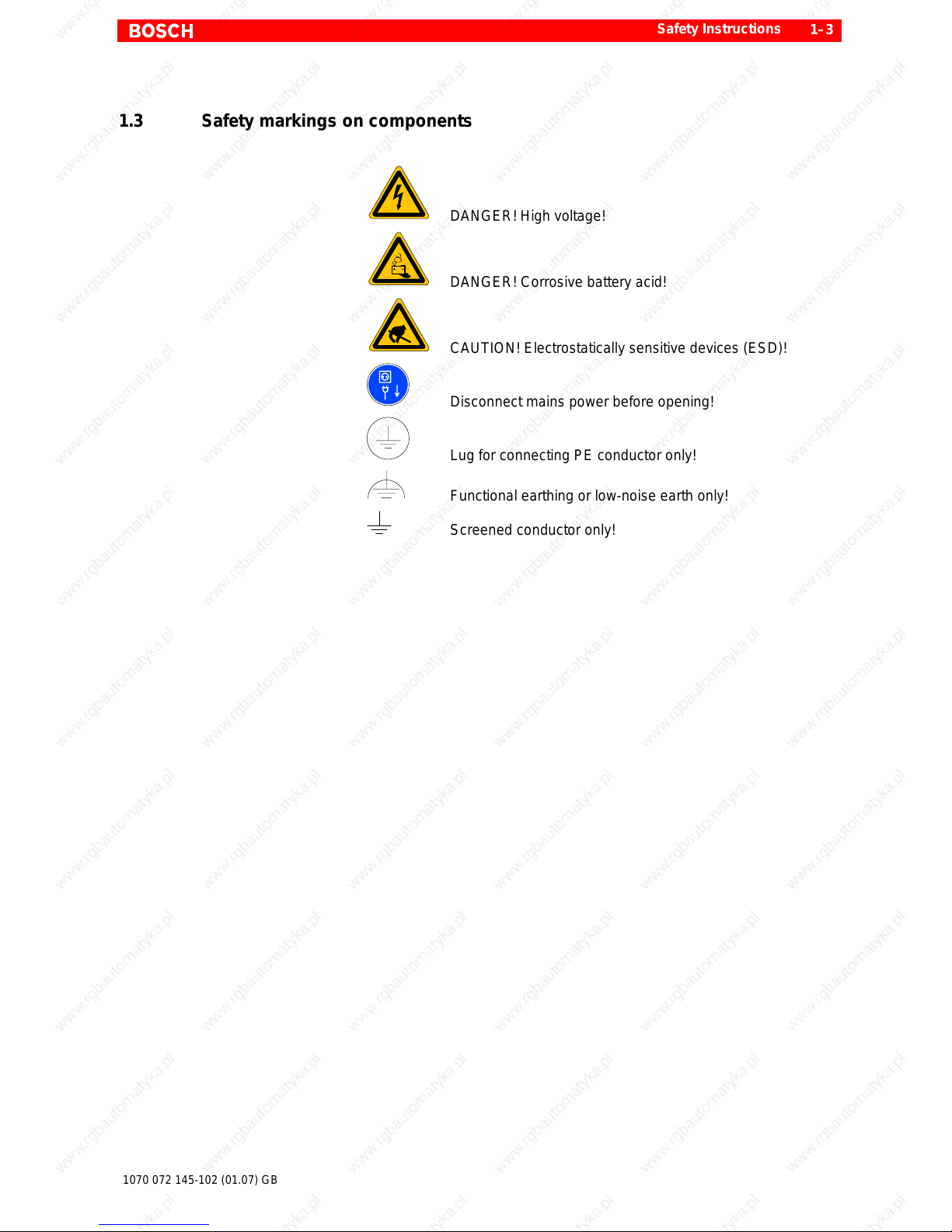
1.3 Safety markings on components
DANGER! High voltage!
DANGER! Corrosive battery acid!
CAUTION! Electrostatically sensitive devices (ESD)!
Disconnect mains power before opening!
Lug for connecting PE conductor only!
Functional earthing or low-noise earth only!
Screened conductor only!
Page 12
Safety Instructions
1–4
1070 072 145-102 (01.07) GB
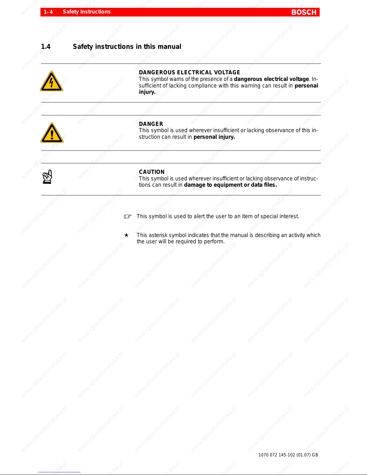
1.4 Safety instructions in this manual
DANGEROUS ELECTRICAL VOLTAGE
This symbol warns of the presence of a dangerous electrical voltage. In-
sufficient of lacking compliance with this warning can result in personal
injury.
DANGER
This symbol is used wherever insufficient or lacking observance of this in-
struction can result in personal injury.
CAUTION
This symbol is used wherever insufficient or lacking observance of instruc-
tions can result in damage to equipment or data files.
. This symbol is used to alert the user to an item of special interest.
L This asterisk symbol indicates that the manual is describing an activity which
the user will be required to perform.
Page 13
Safety Instructions
1–5
1070 072 145-102 (01.07) GB
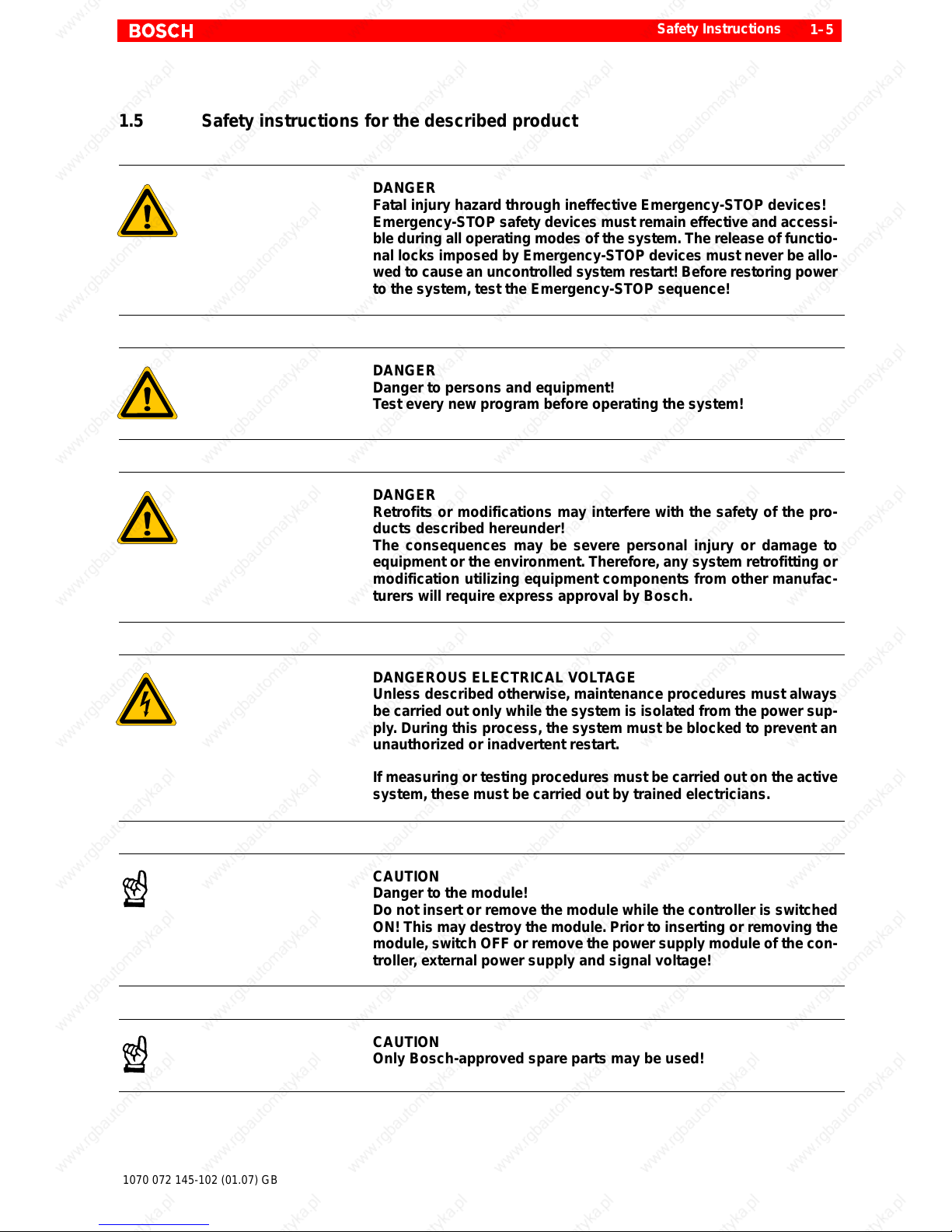
1.5 Safety instructions for the described product
DANGER
Fatal injury hazard through ineffective Emergency-STOP devices!
Emergency-STOP safety devices must remain effective and accessi-
ble during all operating modes of the system. The release of functio-
nal locks imposed by Emergency-STOP devices must never be allo-
wed to cause an uncontrolled system restart! Before restoring power
to the system, test the Emergency-STOP sequence!
DANGER
Danger to persons and equipment!
Test every new program before operating the system!
DANGER
Retrofits or modifications may interfere with the safety of the pro-
ducts described hereunder!
The consequences may be severe personal injury or damage to
equipment or the environment. Therefore, any system retrofitting or
modification utilizing equipment components from other manufac-
turers will require express approval by Bosch.
DANGEROUS ELECTRICAL VOL TAGE
Unless described otherwise, maintenance procedures must always
be carried out only while the system is isolated from the power sup-
ply. During this process, the system must be blocked to prevent an
unauthorized or inadvertent restart.
If measuring or testing procedures must be carried out on the active
system, these must be carried out by trained electricians.
CAUTION
Danger to the module!
Do not insert or remove the module while the controller is switched
ON! This may destroy the module. Prior to inserting or removing the
module, switch OFF or remove the power supply module of the con-
troller, external power supply and signal voltage!
CAUTION
Only Bosch-approved spare parts may be used!
Page 14
Safety Instructions
1–6
1070 072 145-102 (01.07) GB
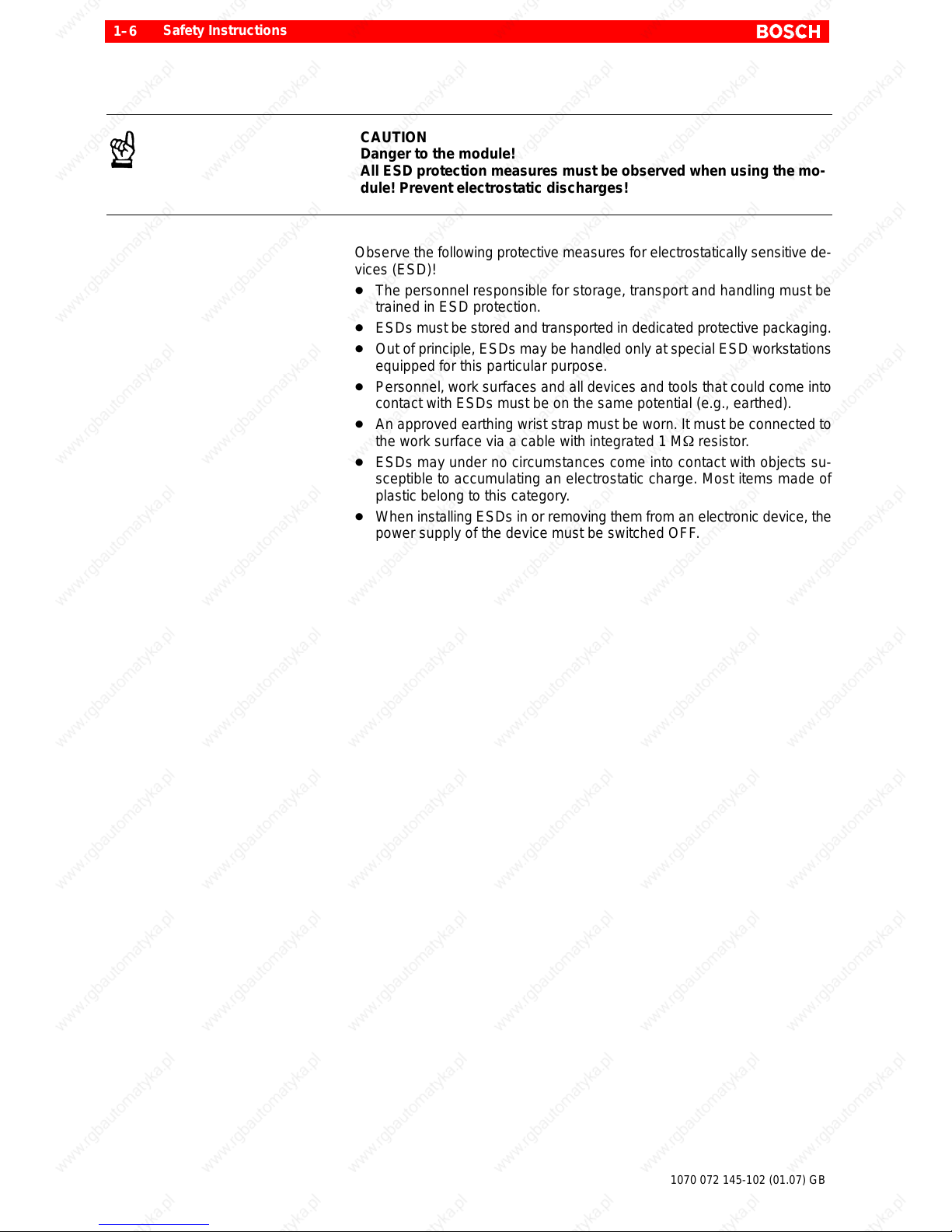
CAUTION
Danger to the module!
All ESD protection measures must be observed when using the mo-
dule! Prevent electrostatic discharges!
Observe the following protective measures for electrostatically sensitive de-
vices (ESD)!
D The personnel responsible for storage, transport and handling must be
trained in ESD protection.
D ESDs must be stored and transported in dedicated protective packaging.
D Out of principle, ESDs may be handled only at special ESD workstations
equipped for this particular purpose.
D Personnel, work surfaces and all devices and tools that could come into
contact with ESDs must be on the same potential (e.g., earthed).
D An approved earthing wrist strap must be worn. It must be connected to
the work surface via a cable with integrated 1 MW resistor.
D ESDs may under no circumstances come into contact with objects su-
sceptible to accumulating an electrostatic charge. Most items made of
plastic belong to this category.
D When installing ESDs in or removing them from an electronic device, the
power supply of the device must be switched OFF.
Page 15
Safety Instructions
1–7
1070 072 145-102 (01.07) GB
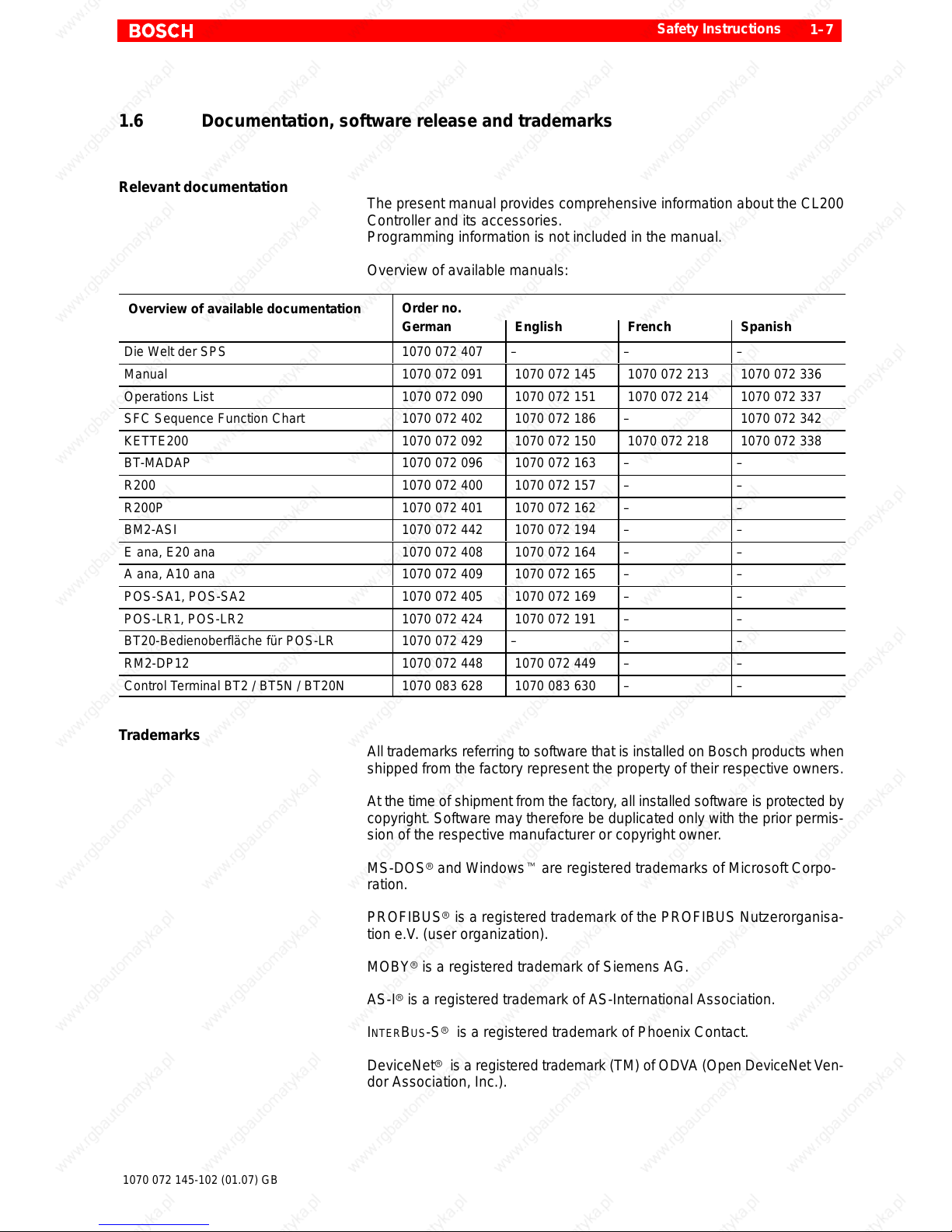
1.6 Documentation, software release and trademarks
Relevant documentation
The present manual provides comprehensive information about the CL200
Controller and its accessories.
Programming information is not included in the manual.
Overview of available manuals:
Overview of available documentation
Order no.
German English French Spanish
Die Welt der SPS 1070 072 407 – – –
Manual 1070 072 091 1070 072 145 1070 072 213 1070 072 336
Operations List 1070 072 090 1070 072 151 1070 072 214 1070 072 337
SFC Sequence Function Chart 1070 072 402 1070 072 186 – 1070 072 342
KETTE200 1070 072 092 1070 072 150 1070 072 218 1070 072 338
BT-MADAP 1070 072 096 1070 072 163 – –
R200 1070 072 400 1070 072 157 – –
R200P 1070 072 401 1070 072 162 – –
BM2-ASI 1070 072 442 1070 072 194 – –
E ana, E20 ana 1070 072 408 1070 072 164 – –
A ana, A10 ana 1070 072 409 1070 072 165 – –
POS-SA1, POS-SA2 1070 072 405 1070 072 169 – –
POS-LR1, POS-LR2 1070 072 424 1070 072 191 – –
BT20-Bedienoberfläche für POS-LR 1070 072 429 – – –
RM2-DP12 1070 072 448 1070 072 449 – –
Control Terminal BT2 / BT5N / BT20N 1070 083 628 1070 083 630 – –
Trademarks
All trademarks referring to software that is installed on Bosch products when
shipped from the factory represent the property of their respective owners.
At the time of shipment from the factory, all installed software is protected by
copyright. Software may therefore be duplicated only with the prior permis-
sion of the respective manufacturer or copyright owner.
MS-DOSr and Windowst are registered trademarks of Microsoft Corpo-
ration.
PROFIBUSr is a registered trademark of the PROFIBUS Nutzerorganisa-
tion e.V. (user organization).
MOBYr is a registered trademark of Siemens AG.
AS-Ir is a registered trademark of AS-International Association.
INTERBUS-Sr is a registered trademark of Phoenix Contact.
DeviceNetr is a registered trademark (TM) of ODVA (Open DeviceNet Ven-
dor Association, Inc.).
Page 16

Safety Instructions
1–8
1070 072 145-102 (01.07) GB
The UL Mark is a registered certification mark of Underwriters Laboratories,
Inc., an independent, not-for-profit product safety testing and certification or-
ganization.
Page 17

System Introduction
2–1
1070 072 145-102 (01.07) GB
2 System Introduction
2.1 Features and Functions
The CL200 is a powerful controller system of compact and modular design.
Application areas
In its minimum configuration, the CL200 facilitates cost efficient deployment
even in the smallest machine compounds. When fully configured with all
available options or deployed as a decentralized controller in a networked
situation, it can handle partial tasks in transfer lines.
Thanks to its networking option and extensive command repertoire, the
CL200 is also capable of assuming controller tasks of the medium perfor-
mance category.
D Packaging machines
D Conveyor technology
D Building automation
D Bottling equipment and racking plants
D Heating, climate control, ventilation and environmental technologies
D Subsections of transfer line construction
D assembly and handling technologies
D Food processing industry
D General applications in mechanical engineering
Page 18
System Introduction
2–2
1070 072 145-102 (01.07) GB
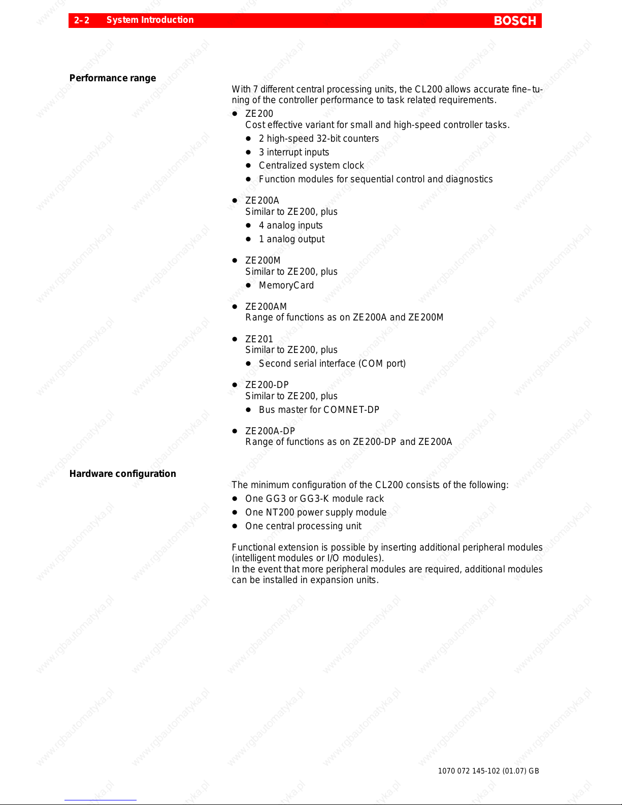
Performance range
With 7 di f ferent central processing units, the CL200 allows accurate fine–tu-
ning of the controller performance to task related requirements.
D ZE200
Cost effective variant for small and high-speed controller tasks.
D 2 high-speed 32-bit counters
D 3 interrupt inputs
D Centralized system clock
D Function modules for sequential control and diagnostics
D ZE200A
Similar to ZE200, plus
D 4 analog inputs
D 1 analog output
D ZE200M
Similar to ZE200, plus
D MemoryCard
D ZE200AM
Range of functions as on ZE200A and ZE200M
D ZE201
Similar to ZE200, plus
D Second serial interface (COM port)
D ZE200-DP
Similar to ZE200, plus
D Bus master for COMNET-DP
D ZE200A-DP
Range of functions as on ZE200-DP and ZE200A
Hardware configuration
The minimum configuration of the CL200 consists of the following:
D One GG3 or GG3-K module rack
D One NT200 power supply module
D One central processing unit
Functional extension is possible by inserting additional peripheral modules
(intelligent modules or I/O modules).
In the event that more peripheral modules are required, additional modules
can be installed in expansion units.
Page 19
System Introduction
2–3
1070 072 145-102 (01.07) GB
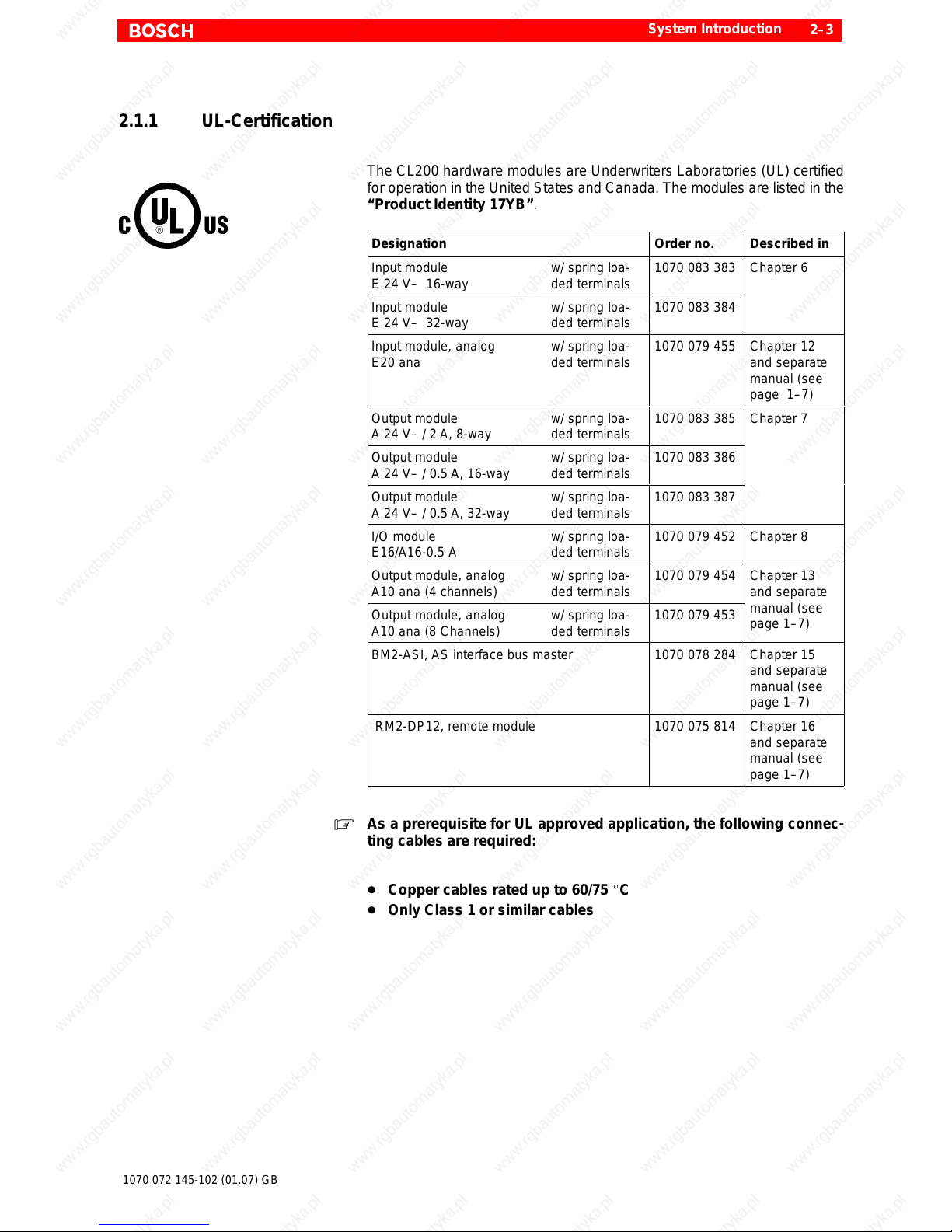
2.1.1 UL-Certification
The CL200 hardware modules are Underwriters Laboratories (UL) certified
for operation in the United States and Canada. The modules are listed in the
“Product Identity 17YB”.
Designation Order no. Described in
Input module
E 24 V– 16-way
w/ spring loa-
ded terminals
1070 083 383
Chapter 6
Input module
E 24 V– 32-way
w/ spring loa-
ded terminals
1070 083 384
Input module, analog
E20 ana
w/ spring loa-
ded terminals
1070 079 455 Chapter 12
and separate
manual (see
page 1–7)
Output module
A 24 V– / 2 A, 8-way
w/ spring loa-
ded terminals
1070 083 385
Chapter 7
Output module
A 24 V– / 0.5 A, 16-way
w/ spring loa-
ded terminals
1070 083 386
Output module
A 24 V– / 0.5 A, 32-way
w/ spring loa-
ded terminals
1070 083 387
I/O module
E16/A16-0.5 A
w/ spring loa-
ded terminals
1070 079 452 Chapter 8
Output module, analog
A10 ana (4 channels)
w/ spring loa-
ded terminals
1070 079 454
Chapter 13
and separate
Output module, analog
A10 ana (8 Channels)
w/ spring loa-
ded terminals
1070 079 453
manual (see
page 1–7)
BM2-ASI, AS interface bus master 1070 078 284 Chapter 15
and separate
manual (see
page 1–7)
RM2-DP12, remote module 1070 075 814 Chapter 16
and separate
manual (see
page 1–7)
. As a prerequisite for UL approved application, the following connec-
ting cables are required:
D Copper cables rated up to 60/75 _C
D Only Class 1 or similar cables
Page 20

System Introduction
2–4
1070 072 145-102 (01.07) GB
2.2 Programming
The CL200 is programmed with the aid of a PC via the serial COM port.
With the use of the PC, the PLC program can also be written without requi-
ring the physical presence of the controller.
The CL200 provides the following options for storing the PLC program:
D Battery backed RAM memory
D Flash EPROM memory
D MemoryCard
Program Structure
The PLC program is subdivided into clearly defined and technologically allo-
cated program modules.
Programming
The PLC program is produced with the use of the Bosch proprietary WinSPS
software application.
The PLC program can be produced in the form of
D IL instruction list
D LD ladder diagram
D FUD function diagram
D SFC sequential function chart
with optional use of symbolic or absolute operands.
The programming language is based on DIN 19239.
PLC program documentation
The clearly structured and easily understood PLC program documentation
providing cross-reference lists supports the user in the case of quick system
startup, system troubleshooting, or when adapting the controller to new ap-
plications.
Both in the form of the screen display of the programming unit and as hard-
copy, the PLC program documentation provides a substantial rate of com-
ments.
Page 21
System Introduction
2–5
1070 072 145-102 (01.07) GB
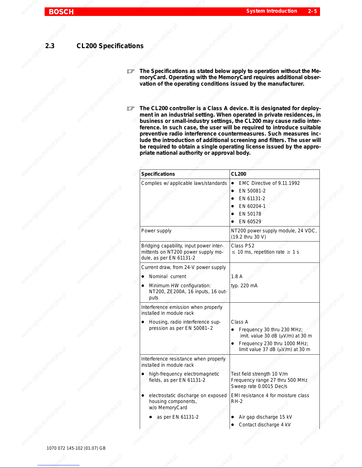
2.3 CL200 Specifications
. The Specifications as stated below apply to operation without the Me-
moryCard. Operating with the MemoryCard requires additional obser-
vation of the operating conditions issued by the manufacturer.
. The CL200 controller is a Class A device. It is designated for deploy-
ment in an industrial setting. When operated in private residences, in
business or small-industry settings, the CL200 may cause radio inter-
ference. In such case, the user will be required to introduce suitable
preventive radio interference countermeasures. Such measures inc-
lude the introduction of additional screening and filters. The user will
be required to obtain a single operating license issued by the appro-
priate national authority or approval body.
Specifications CL200
Complies w/ applicable laws/standards D EMC Directive of 9.11.1992
D EN 50081-2
D EN 61131-2
D EN 60204-1
D EN 50178
D EN 60529
Power supply NT200 power supply module, 24 VDC,
(19.2 thru 30 V)
Bridging capability, input power inter-
mittents on NT200 power supply mo-
dule, as per EN 61131-2
Class PS2
v 10 ms, repetition rate w 1 s
Current draw, from 24-V power supply
D Nominal current 1.8 A
D Minimum HW configuration:
NT200, ZE200A, 16 inputs, 16 out-
puts
typ. 220 mA
Interference emission when properly
installed in module rack
D Housing, radio interference sup-
pression as per EN 50081–2
Class A
D Frequency 30 thru 230 MHz;
imit. value 30 dB (mV/m) at 30 m
D Frequency 230 thru 1000 MHz;
limit value 37 dB (mV/m) at 30 m
Interference resistance when properly
installed in module rack
D high-frequency electromagnetic
fields, as per EN 61131-2
Test field strength 10 V/m
Frequency range 27 thru 500 MHz
Sweep rate 0.0015 Dec/s
D electrostatic discharge on exposed
housing components,
w/o MemoryCard
EMI resistance 4 for moisture class
RH-2
D as per EN 61131-2 D Air gap discharge 15 kV
D Contact discharge 4 kV
Page 22
System Introduction
2–6
1070 072 145-102 (01.07) GB
Specifications CL200
D Line transient interference
D Rapid burst pulses, symm.,
as per EN 61131-2
D 2 kV for power supply module and
digital inputs/outputs
D 1 kV for analog inputs / outputs,
counter and interrupt inputs, serial
interfaces
D Dampened sinewave 1 MHz,
symm., as per EN 61131-2
1 kV for
D NT200 power supply module
D Digital inputs / outputs
D All power supply connections on
modules
Insulation test voltage, as per
EN 61131-2
D 350 V, AC voltage
D 500 V, DC voltage
D 500 V Pulse, 1.2 / 50 ms
Shock and vibration resistance
D Sinewave-shaped oscillations on
X, Y and Z axes, to EN 61131-2
D 10 thru 57 Hz
D 0.0375 mm amplitude, contin.
D 0.075 mm amplitude, occas.
D 57 thru 150 Hz
D 0.5 g, continuous
D 1 g, occasional
D Shock loads on X, Y, and Z axes,
as per EN 61131-2
11 ms semi-sinewave 15 g
Corrosion, chemical resistance
The ambient air must be free of eleva-
ted concentrations of acids, alkali, cor-
rosives, salts, metallic vapours, or
other electrically conductive pollutants.
Pollution level, as per VDE 0110 Part1 2
The ambient air must be dust–free.
Housing and installation environments
accommodating the module rack must
comply with IP 54.
Protection category, as per EN 60529 IP 20
Safety class, as per EN 50178 Class Ι
Humidity rating, as per EN 61131-2 RH-2, 5 through 95 %, condensation
not permitted
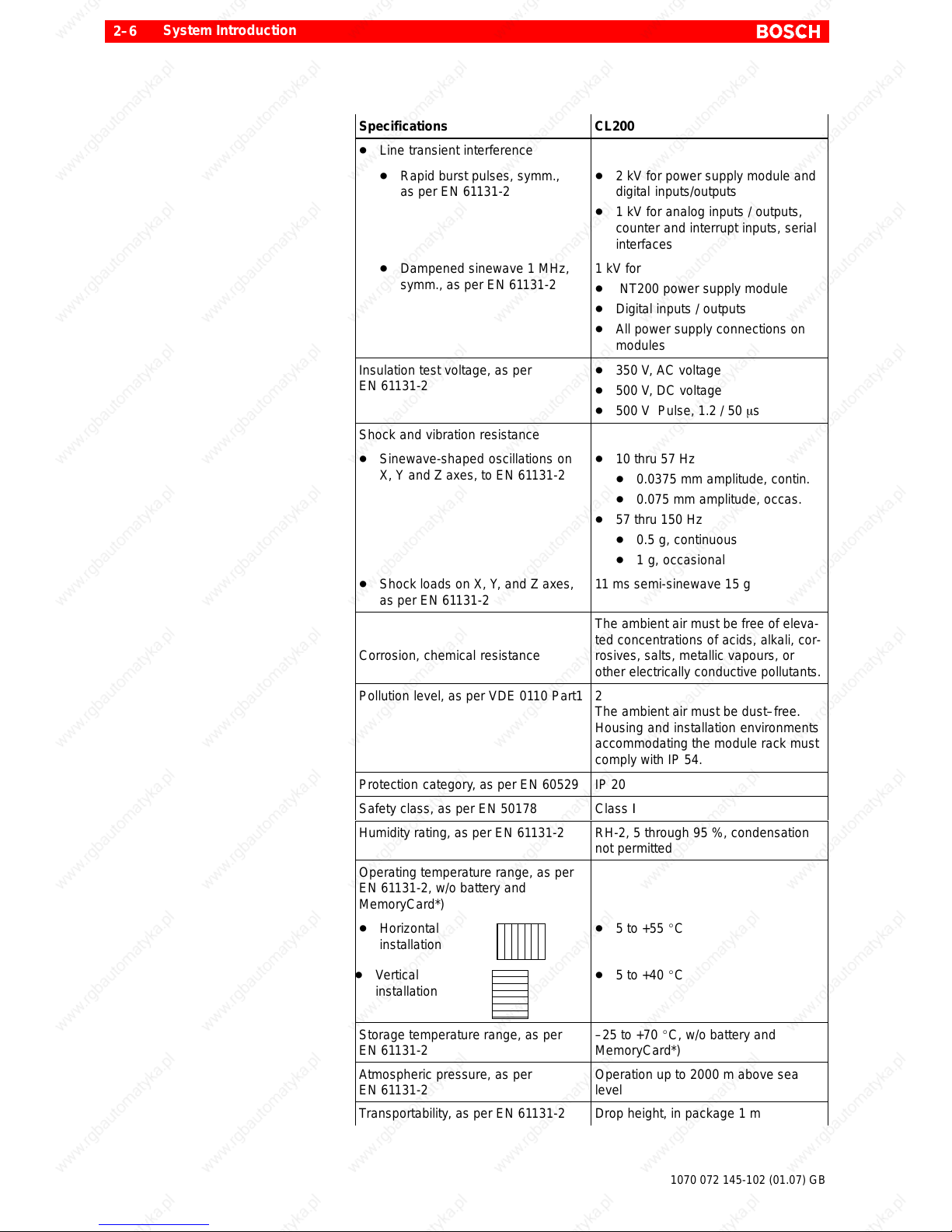
Operating temperature range, as per
EN 61131-2, w/o battery and
MemoryCard*)
D Horizontal
installation
D 5 to +55 _C
D Vertical
installation
D 5 to +40 _C
Storage temperature range, as per
EN 61131-2
–25 to +70 _C, w/o battery and
MemoryCard*)
Atmospheric pressure, as per
EN 61131-2
Operation up to 2000 m above sea
level
Transportability, as per EN 61131-2 Drop height, in package 1 m
Page 23
System Introduction
2–7
1070 072 145-102 (01.07) GB
Specifications CL200
Weight, GG3 module rack D Net weight, 1kg
D Fully populated, approx. 3 kg
Weight, GG3-K module rack D Net weight, 0.58 kg
D Fully populated, approx. 1.8 kg
Dimensions, GG3 , w/ population
in mm (B x H x T)
224 x 184 x 126
Dimensions, GG3-K, w/ population
in mm (B x H x T)
132 x 184 x 126
*) Battery and MemoryCard are subject to the specification of the respective
manufacturer.
. The backplane must always be in a vertical position.
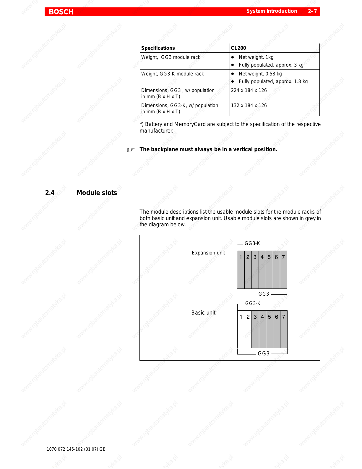
2.4 Module slots
The module descriptions list the usable module slots for the module racks of
both basic unit and expansion unit. Usable module slots are shown in grey in
the diagram below.
1234567
Basic unit
GG3
1234567
Expansion unit
GG3
GG3-K
GG3-K
Page 24

System Introduction
2–8
1070 072 145-102 (01.07) GB
Notes:
Page 25
Module Racks
3–1
1070 072 145-102 (01.07) GB
3 Module Racks
3.1 Overview
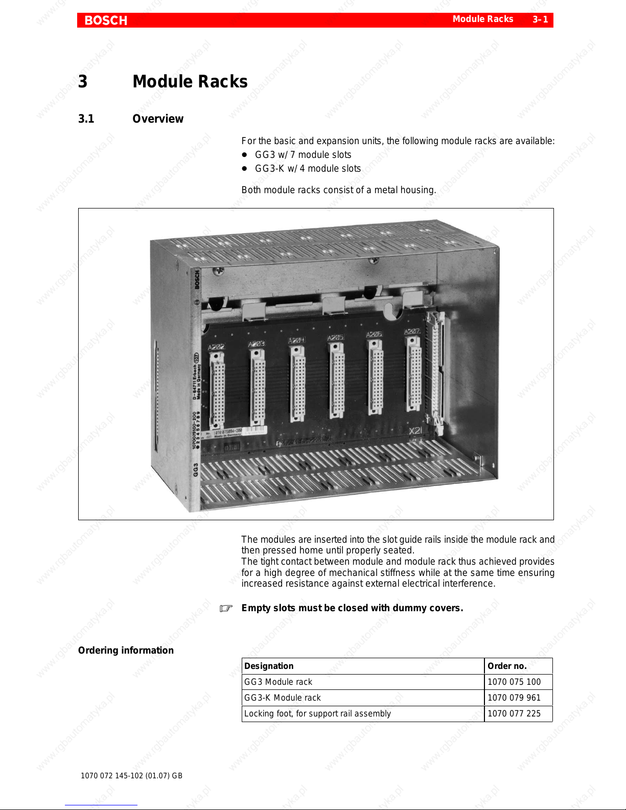
For the basic and expansion units, the following module racks are available:
D GG3 w/ 7 module slots
D GG3-K w/ 4 module slots
Both module racks consist of a metal housing.
The modules are inserted into the slot guide rails inside the module rack and
then pressed home until properly seated.
The tight contact between module and module rack thus achieved provides
for a high degree of mechanical stiffness while at the same time ensuring
increased resistance against external electrical interference.
. Empty slots must be closed with dummy covers.
Ordering information
Designation Order no.
GG3 Module rack 1070 075 100
GG3-K Module rack 1070 079 961
Locking foot, for support rail assembly 1070 077 225
Page 26
Module Racks
3–2
1070 072 145-102 (01.07) GB
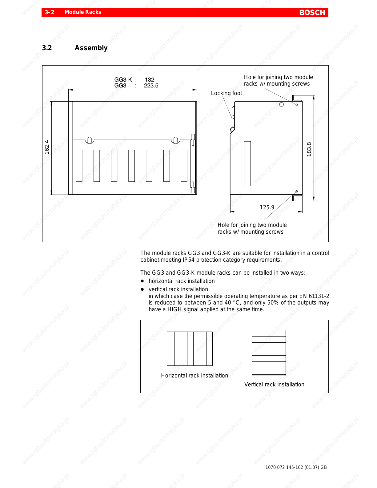
3.2 Assembly
Hole for joining two module
racks w/ mounting screws
Hole for joining two module
racks w/ mounting screws
Locking foot
GG3 : 223.5
GG3K : 132
162.4
183.8
125.9
The module racks GG3 and GG3-K are suitable for installation in a control
cabinet meeting IP54 protection category requirements.
The GG3 and GG3-K module racks can be installed in two ways:
D horizontal rack installation
D vertical rack installation,
in which case the permissible operating temperature as per EN 61 131-2
is reduced to between 5 and 40 _C, and only 50% of the outputs may
have a HIGH signal applied at the same time.
Vertical rack installation
Horizontal rack installation
Page 27
Module Racks
3–3
1070 072 145-102 (01.07) GB
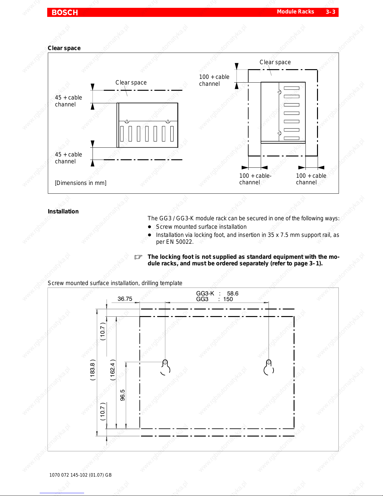
Clear space
Clear space
45 + cable
channel
45 + cable
channel
Clear space
100 + cable
channel
100 + cable-
channel
100 + cable
channel
[Dimensions in mm]
Installation
The GG3 / GG3-K module rack can be secured in one of the following ways:
D Screw mounted surface installation
D Installation via locking foot, and insertion in 35 x 7.5 mm support rail, as
per EN 50022.
. The locking foot is not supplied as standard equipment with the mo-
dule racks, and must be ordered separately (refer to page 3–1).
Screw mounted surface installation, drilling template
GG3K : 58.6
GG3 : 150
36.75
( 183.8 )
( 10.7 )
( 162.4 )
96.5
( 10.7 )
Page 28
Module Racks
3–4
1070 072 145-102 (01.07) GB
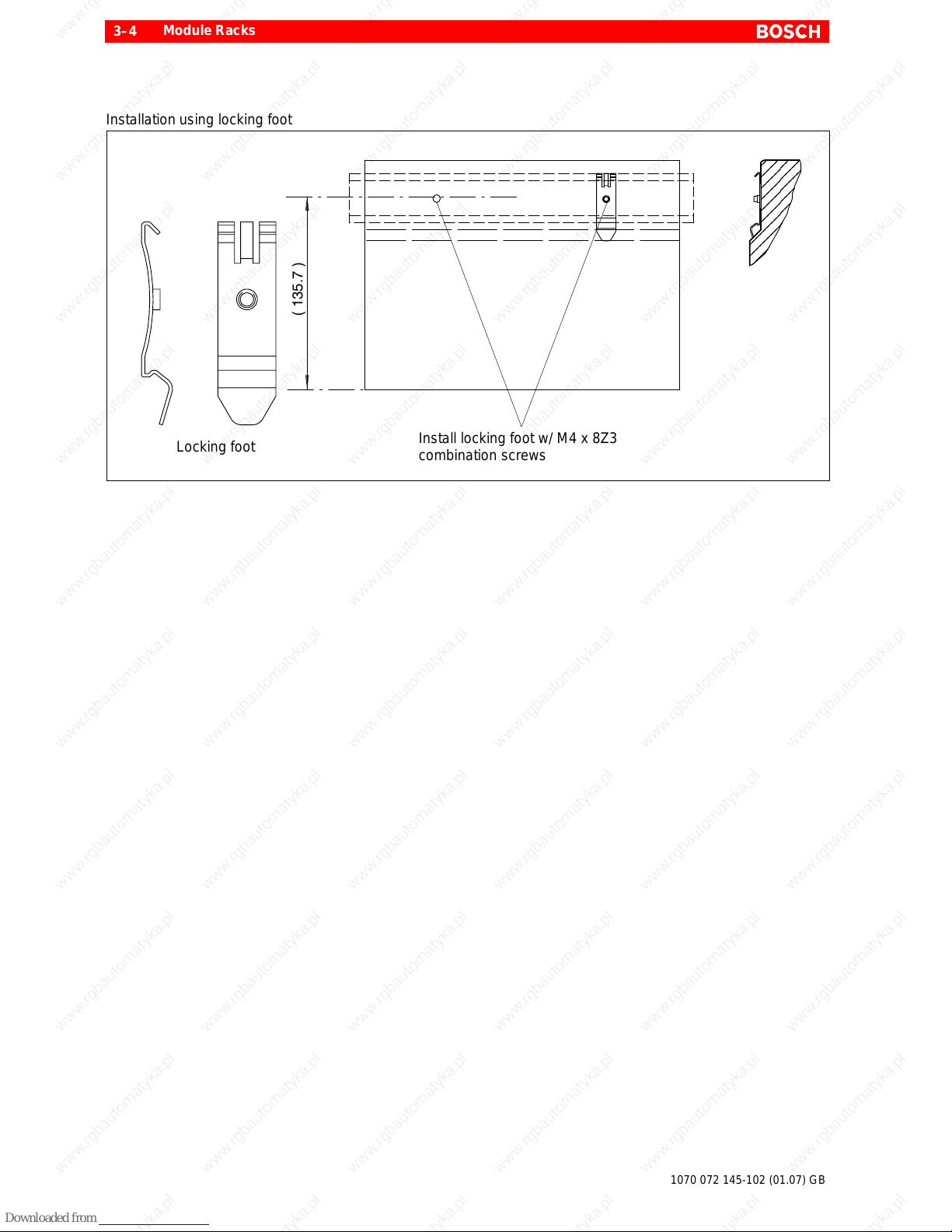
Installation using locking foot
Install locking foot w/ M4 x 8Z3
combination screws
Locking foot
( 135.7 )
Page 29
Module Racks
3–5
1070 072 145-102 (01.07) GB
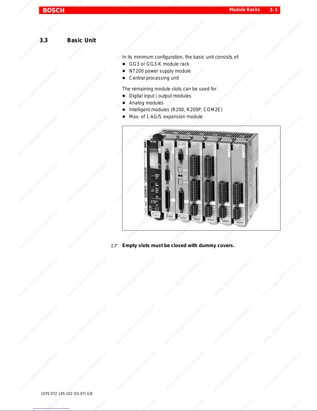
3.3 Basic Unit
In its minimum configuration, the basic unit consists of:
D GG3 or GG3-K module rack
D NT200 power supply module
D Central processing unit
The remaining module slots can be used for
D Digital input / output modules
D Analog modules
D Intelligent modules (R200, R200P, COM2E)
D Max. of 1 AG/S expansion module
. Empty slots must be closed with dummy covers.
Page 30
Module Racks
3–6
1070 072 145-102 (01.07) GB
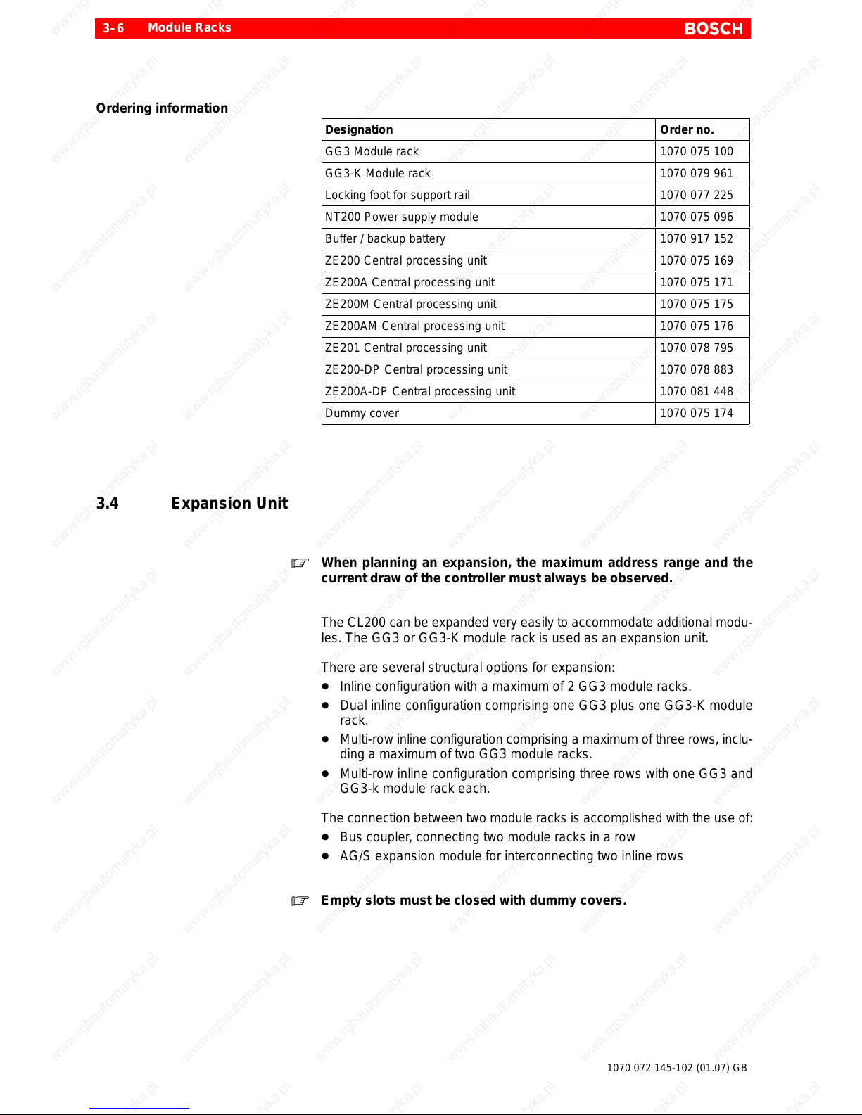
Ordering information
Designation Order no.
GG3 Module rack 1070 075 100
GG3-K Module rack 1070 079 961
Locking foot for support rail 1070 077 225
NT200 Power supply module 1070 075 096
Buffer / backup battery 1070 917 152
ZE200 Central processing unit 1070 075 169
ZE200A Central processing unit 1070 075 171
ZE200M Central processing unit 1070 075 175
ZE200AM Central processing unit 1070 075 176
ZE201 Central processing unit 1070 078 795
ZE200-DP Central processing unit 1070 078 883
ZE200A-DP Central processing unit 1070 081 448
Dummy cover 1070 075 174
3.4 Expansion Unit
. When planning an expansion, the maximum address range and the
current draw of the controller must always be observed.
The CL200 can be expanded very easily to accommodate additional modu-
les. The GG3 or GG3-K module rack is used as an expansion unit.
There are several structural options for expansion:
D Inline configuration with a maximum of 2 GG3 module racks.
D Dual inline configuration comprising one GG3 plus one GG3-K module
rack.
D Multi-row inline configuration comprising a maximum of three rows, inclu-
ding a maximum of two GG3 module racks.
D Multi-row inline configuration comprising three rows with one GG3 and
GG3-k module rack each.
The connection between two module racks is accomplished with the use of:
D Bus coupler, connecting two module racks in a row
D AG/S expansion module for interconnecting two inline rows
. Empty slots must be closed with dummy covers.
Page 31

Module Racks
3–7
1070 072 145-102 (01.07) GB
Ordering information
Designation Order no.
GG3 Module rack 1070 075 100
GG3-K Module rack 1070 079 961
Locking foot for support rail 1070 077 225
Bus coupler 1070 075 110
AG/S Expansion module 1070 075 916
AG/S Connecting cable, 0.3 m 1070 077 162
Dummy cover 1070 075 174
Page 32

Module Racks
3–8
1070 072 145-102 (01.07) GB
3.4.1 Expansion Structure
Horizontal installation, inline
One inline row of modules consists of max. 2 module GG3 or GG3-K module
racks; alternatively, it may comprise one GG3 plus one GG-K module rack.
This expansion unit is mounted directly beside the basic unit (see diagram):
NT200
ZE200
When assembled side-by-side, two GG3 module racks conform to the
19-inch EIA standard.
GG3-K + GG3-K :264
GG3 + GG3-K : 355.50
GG3 + GG3 : 447
GG3-K : 132
GG3 : 223.5
GG3 or GG3-K
Two module racks joined
with mounting screws
162.4
GG3 or GG3-K
GG3-K : 132
GG3 : 223.5
Page 33

Module Racks
3–9
1070 072 145-102 (01.07) GB
L Assembling / installing module racks
D Based on drilling template
or
D On support rail, for multiple-row expansion
GG3K : 58.6
GG3 : 150
36.75 73,5
( 183.8 )
( 10.7 )
( 162.4 )
96.5
GG3K : 58.6
GG3 : 150
L Use bus coupler to establish bus connection between module racks.
Bus coupler
Use mounting screws
to join module racks
L Use M3x5 filister head screw and lock washer to join module racks.
Page 34

Module Racks
3–10
1070 072 145-102 (01.07) GB
Horizontal installation, multi-row inline configuration
In the event that more than two module racks are needed, a multi-row expan-
sion is configured with the use of the AG/S expansion module:
D Maximum possible configuration of 6 module racks
D CPU and power supply module always installed at bottom left
D AG/S must always be inserted in far end right hand module slot.
. The CL200 controller accommodates a maximum of three inline expan-
sion rows.
When using the AG/S, the maximum permissible distance between to mo-
dule racks is 5 meters.
Maximum expansion:
Basic unit plus 5 expansion units
NT200
ZE200
NT200
ZE200
Basic row
Expansion row 1
Expansion row 2
AG/S
AG/S
AG/S
Page 35

Module Racks
3–11
1070 072 145-102 (01.07) GB
Surface mounted installation
Clear space
Clear space
w 250 + Cable channel width
w 250 + Cable channel width
100 + cable channel width
100 + Cable channel width
. The height of the cable channel should not exceed 65 mm.
Page 36

Module Racks
3–12
1070 072 145-102 (01.07) GB
Support rail installation
Clear space
Clear space
w 250 + Cable channel width
w 250 + Cable channel width
100 + Cable channel width
100 + Cable channel width
. The height of the cable channel should not exceed 65 mm.
Page 37

Module Racks
3–13
1070 072 145-102 (01.07) GB
Vertical module rack installation
The vertical arrangement of the CL200 is permissible only in a single-row
configuration. The following restrictions must be observed:
D The maximum permitted configuration is two module racks.
D CPU and power supply module always to occupy bottom slots.
Maximum expansion,
Basic unit plus 1 expansion unit
NT200
ZE200
Clear space
100 + Cable
channel
100 +Cable
channel
100 +Cable
channel
. When using vertical installation, the permissible operating tempera-
ture as per EN 61131-2 is reduced to between 5 and 40 _C, and only 50%
of the outputs may have a HIGH signal applied at the same time.
Page 38

Module Racks
3–14
1070 072 145-102 (01.07) GB
Notes:
Page 39

NT200 Power Supply Module
4–1
1070 072 145-102 (01.07) GB
4 NT200 Power Supply Module
4.1 Features and Functions
The NT200 power supply module performs the following functions:
D Provision of internal operating voltages:
D 5 V for the central processing unit
D 3.4 V memory backup battery voltage
D 7.5 V for peripheral modules
D 12 V ISO for 20 mA interface
D Undervoltage monitoring of 24 V power supply
D Bridging power intermittents in 24 V power supply
D Monitoring internal power supply
D In the event of a failure of the 24 V power supply, the buffered controller
memory is powered by a backup battery.
D Monitoring the backup battery
. The power supply module in the basic unit does not provide 24 V power
for peripheral modules, signal encoders and actuators. These require
a separate 24 V power supply. Refer to information in section 17.1.
Page 40

NT200 Power Supply Module
4–2
1070 072 145-102 (01.07) GB
Module slot
1234567
Basic unit
GG3
1234
GG3-K
or
DANGEROUS ELECTRICAL VOL TAGE
Hazard to personnel!
Operation of the NT200 power supply module generates voltage
peaks which significantly exceed the functional extra low voltage.
The module may be powered up only while inserted in the module
rack.
CAUTION
Do not insert or remove the module while the controller is switched
ON! This may destroy the module. Prior to inserting or removing the
module, switch OFF or remove the power supply module of the con-
troller, external power supply and signal voltage!
CAUTION
Risk of module damage!
Observe all ESD protection measures when handling modules and
components! Prevent electrostatic discharges!
. Observe instructions in Chapter 17, Installation.
Page 41

NT200 Power Supply Module
4–3
1070 072 145-102 (01.07) GB
4.2 Display and Control Elements
Memory backup battery
24 V power supply connector
Low Battery LED
The Low Battery LED indicates battery failure.
Battery Reset button
The Battery Reset button performs two functions:
D RESET and acknowledgement of a battery failure.
D Activation of battery load test.If a fault is detected, the Low Battery war-
ning signal S30.7 in the system area goes HIGH.
Page 42

NT200 Power Supply Module
4–4
1070 072 145-102 (01.07) GB
PG Mode LED
. Refer to Chapter 5, Central Processing Unit, section 5.2, Display and
Control Elements
Copy / Stop / Run switch/button
. Refer to Chapter 5, Central Processing Unit, section 5.2, Display and
Control Elements
Stop LED
. Refer to Chapter 5,Central Processing Unit, section 5.2, Display and
Control Elements
5V / 7.5V LED
When this LED illuminates, the 5 V and /.5 V supply voltages for central pro-
cessing unit and periphery modules are present.
X10 connector
The X10 connector comprises the terminal for the 24 V power (form factor
5.08).
Page 43

NT200 Power Supply Module
4–5
1070 072 145-102 (01.07) GB
4.3 Memory Backup Battery
The memory backup battery assists the central backup of remanent areas
for markers, timers, counters, data field and PLC program. The backup bat-
tery powers the internal RAM onboard the central processing unit in the
event of a failure of the 24 V power supply, and upon switching off the NT200
power supply module.
Module
typ. current draw in mA at
25 _C 55 _C
NT200 18 28
Central processing module 6 28
The service life of the memory backup battery depends on:
D Ambient temperature
D T ime interval for which the controller is switched off
. Replace the memory backup battery after 1!/$ years at the latest.
The CL200 uses lithium backup batteries. They contain less than 0.5 g of
lithium, and are hermetically sealed. They are not considered a hazardous
substance when transported in their original package.
Backup batteries:
D Store in a cool, dry place, at max. 35 _C recommended storage temp.
D Do not short-circuit
D Do not recharge
D Do not deep-discharge
D Do not incinerate
D Do not connect with reverse polarity
D Do not damage or open cells
Low Battery warning
The backup battery is tested on the following occasions:
D Subsequent to powering up the 24 V power supply
D When pressing the Battery Reset button on the front panel of the power
supply module
A missing battery or the detection of low battery voltage causes the S30.7
Low Battery signal in the system area to go HIGH.
The same occurs when the battery voltage drops below 2.6 V while the con-
troller is switched on.
Battery failure
A battery failure is detected subsequent to Power-On in the following cases:
D The backup battery is missing.
D Central processing unit or NT200 power supply module has been remo-
ved prior to Power-On.
Page 44

NT200 Power Supply Module
4–6
1070 072 145-102 (01.07) GB
Battery failure is indicated by the Low Battery LED, and the S27.2 battery
fault bit goes HIGH.
During RAM operation, when a fault has been detected in the backup bat-
tery, the central processing unit remains in STOP mode, and the PLC pro-
gram is deleted.
The battery fault bit can be acknowledged by pressing the Battery Reset but-
ton on the front panel of the NT200 power supply module.
Replacing the battery
CAUTION
Backup battery discharge hazard!
Insert backup battery only while module is inserted in module rack.
Otherwise backup battery may be discharged when the module is re-
sting on an electrically conductive surface.
CAUTION
Loss of data!
Removing the backup battery with the 24 V power supply switched
off will cause the loss of all remanent data and of the PLC program
stored in RAM!
Replace backup battery only while 24 V power supply is switched on!
L Push the battery compartment cover downward and remove.
Battery cover
Page 45

NT200 Power Supply Module
4–7
1070 072 145-102 (01.07) GB
L Remove old backup battery.
This causes a battery warning to be indicated in the system area and on the
programming device.
L Gently tap new backup battery on hard surface to break internal oxide layer .
L Ensuring correct polarity, insert new battery.
L Reinstall battery compartment cover, and push upward.
L To cancel the battery warning, press the Battery Reset button on the front
panel of the NT200 power supply module.
. The old backup battery (lithium battery) must be disposed of as hazar-
dous waste (i.e., in Germany under waste code number 35 325). The ac-
ceptance provisions of the disposal site must be observed.
4.4 Specifications
Specifications NT200
Power supply, as per EN 61131-2 24 VDC, 19.2 through 30 V
Bridging capability, intermittents on power
supply module, as per EN 61131-2
Class PS2 v10 ms,
repetition rate w 1 s
Current draw from 24 V power supply
D Rated current 1.8 A
D Minimum configuration: NT200,
ZE200A, 16 inputs, 16 outputs
typ. 220 mA
Peak inrush current v40 A
Duration of peak inrush current v5 ms
Power supply, voltage rated, for
D Central processing unit
D Memory backup
D Peripheral modules
D 20mA interface
5 V
3.4 V
7.5 V
12 V ISO
Power supply, current rated
D 5 V for central processing unit
and intelligent modules
D 7.5 V for peripheral modules
D 12 V ISO for 20mA interface
max. 2.7 A
1.5 A
max. 150 mA
Memory backup battery
D Type
D Capacity
D Battery voltage
D Effective service life
Lithium battery
AA
w 850 mAh
3.6 V
1 year (minimum)
Width 1 slot
Weight 400 g
Page 46

NT200 Power Supply Module
4–8
1070 072 145-102 (01.07) GB
Ordering information
Designation Order no.
NT200 Power supply module 1070 075 096
Memory backup battery 1070 917 152
Page 47

Central Processing Unit
5–1
1070 072 145-102 (01.07) GB
5 Central Processing Unit
5.1 Features and Functions
ZE200 ZE200A
ZE200M
ZE200AM
ZE201
ZE200-DP
ZE200A-DP
Page 48

Central Processing Unit
5–2
1070 072 145-102 (01.07) GB
Unit functions
D Decoding and processing instructions and commands contained in the
PLC program
D Memory management for data received from peripherals
D Detection and processing of interrupt signals
D System monitoring
PLC program memory
To facilitate PLC program storage, the central processing units feature two
internal memory areas.
D 128 kB of internal RAM
D 128 kB Flash-EPROM memory
With a memory backup battery installed in the NT200 power supply mo-
dule, the PLC program can be processed from within the internal 128 kB
RAM.
When operating without backup battery, the PLC program is processed
from within the 128 kB Flash-EPROM memory.
Also possible is mixed operation using both RAM and Flash-EPROM me-
mory for data storage.
When operating with RAM or Flash-EPROM, the following memory capaci-
ties are available to store the application program:
D 12 kB instructions plus 16 kB data modules, OR
D 18 k instructions without data modules
These values are doubled in mixed operation.
The selection of RAM and Flash-EPROM memory and the definition of
mixed operation is accomplished with the use of the PLC utility program. Re-
fer also to order no. for “CL200 Operations List”, in section 1.6.
Functional features
D Cyclical program processing w/ OM1 organization module
D Setting system parameters in OM2 organization module
D Controlling program processing via organization module OM5 or OM7
D Error management in OM9 organization module
D 2 organization modules for timer controlled functions
D 3 organization modules for interrupt inputs
D Fixation of inputs/outputs and markers
The instruction set used with the CL200 is upward compatible for use with
the CL400 and CL500 controllers.
ZE200, ZE200A, ZE200M, ZE200AM, ZE201, ZE200-DP, ZE200A-DP
Seven variants of the central processing unit are available to ensure optimi-
zed and cost effective adaptation of the CL200 to a variety of tasks:
D ZE200
System clock, high-speed counters, interrupt inputs
D ZE200A
System clock, high-speed counters, interrupt inputs, 4 analog inputs, 1
analog output
Page 49

Central Processing Unit
5–3
1070 072 145-102 (01.07) GB
D ZE200M
System clock, high-speed counters, interrupt inputs, MemoryCard
D ZE200AM
System clock, high-speed counters, interrupt inputs, 4 analog inputs, 1
analog output, MemoryCard
D ZE201
System clock, high-speed counters, interrupt inputs, 2nd serial interface
D ZE200-DP
System clock, high-speed counters, interrupt inputs, PROFIBUS-DP in-
terface. Handles the tasks of a bus master, and supports all DP compati-
ble slave devices.
D ZE200A-DP
System clock, high-speed counters, interrupt inputs, 4 analog inputs, 1
analog output, PROFIBUS-DP interface. Handles the tasks of a bus ma-
ster, and supports all DP compatible slave devices.
System clock
The system clock data is stored centrally in the S128 to S134 system area; it
is refreshed cyclically with every I/O image.
D The date values must be entered correctly.
D If the entry of a day of the week is required, the date must be entered cor-
rectly, and complete with day-of-week information.
High-speed counters
Two mutually independent 32-bit forward and reverse counters are availa-
ble. Each counter has two limit values. One of these counters also supports
position decoding via incremental rotary encoders.
. Refer to section 5.4.2, “X71 Interrupt and High-speed Counter Inputs”.
Interrupt inputs
The central processing units of the CL200 feature three 24 V interrupt inputs.
. Refer to section 5.4.2, “X71 Interrupt and High-speed Counter Inputs”.
Analog inputs and outputs
The analog output can supply a current or voltage rated signal.
. Refer to section 5.4.3, “X72 Analog Inputs and Outputs”.
MemoryCard
Central processing units ZE200M and ZE200AM feature a MemoryCard
slot. The PLCV program can be backed up to or loaded from a MemoryCard.
In addition, all central processing units facilitate program storage also in in-
ternal Flash-EPROM memory.
. See also section 5.3, “MemoryCard”.
Page 50

Central Processing Unit
5–4
1070 072 145-102 (01.07) GB
Second serial interface
The ZE201 provides a second serial interface with additional transmission
protocols.
COMNET -DP interface
The ZE200-DP and ZE200A-DP feature a PROFIBUS-DP interface (mar-
ked “COMNET-DP” on the module) for field bus connection.
Module slot
CAUTION
Do not insert or remove the module while the controller is switched
ON! This may destroy the module. Prior to inserting or removing the
module, switch OFF or remove the power supply module of the con-
troller, external power supply and signal voltage!
CAUTION
Risk of module damage!
Observe all ESD protection measures when handling the module!
Prevent electrostatic discharges!
1234567
Basic unit
GG3
ZE200
ZE200A
1234567
Basic unit
GG3
ZE200M
ZE200AM
1234
GG3-K
ZE201
ZE200DP
1234
GG3-K
ZE200ADP
Page 51

Central Processing Unit
5–5
1070 072 145-102 (01.07) GB
5.2 Display and Control Elements
The display and control elements for the central processing units are located
on the NT200 power supply module. The ZE200-DP features two additional
status LEDs and one Send LED to monitor the operation of the PROFIBUS-
DP interface.
Page 52

Central Processing Unit
5–6
1070 072 145-102 (01.07) GB
PG Mode LED
Stop LED on NT200
The PG Mode and Stop LEDs indicate the following controller operating sta-
tuses:
PG Mode Stop LED display Explanation
f Extinguished Normal operating status
F Illuminated D Outputs disabled
D Inputs / outputs fixed
FF Flashing Copying:
D RAM ³ Flash-EPROM
D RAM ³ MemoryCard
f Extinguished Controller in Run mode
F Illuminated Controller in Stop mode
FF Flashing Copying error:
D Flash-EPROM ³ RAM
D RAM ³ MemoryCard
FF FF Simultaneous flashing, 2 Hz No firmware found
FF FF alternating flashing Internal error, displayed in PLC utility program
FFFF FFFF rapid simultaneous flashing, 8 Hz Defective central processing unit
Copy / Stop / Run switch/button
The switch provides two positions to select the the operating status of the
controller, and one pushbutton position for the Copy function:
D Stop mode
D Run mode
D Copy procedure: – at Power-ON
– during standard operation
. Refer also to order no. for “CL200 Operations List”, in section 1.6,
chapter “Memory Management”.
Page 53

Central Processing Unit
5–7
1070 072 145-102 (01.07) GB
Status 1 LED
Status 2 LED
on ZE200-DP
and ZE200A-DP
The Status 1 and Status 2 LEDs indicate the following operating statuses of
the PROFIBUS-DP interface, and of the ZE200-DP and ZE200A-DP central
processing units.
Status 1 Status 2 LED display Explanation
f f Extinguished Normal operation
F Illuminated Default master set is loaded. Factory shipped state
and/or master parameter set after RESET. DP configu-
ration must be loaded (via WinDP software).
FF Flashing One or more slaves report
D Slave configuration error (SKF)
D Slave not reachable (SNE)
D Slave not ready for cyclical data traffic (SNB).
(The BM-DP is not operated in Auto CLAB mode [Er-
ror_Action_Flag=0])
F F Illuminated When Stop LED on power supply (NT200) also illumi-
nates:
D Startup initialization routine (after Power-ON) is in
progress. Central processing unit is in Stop mode.
DP bus master is attempting to start using availa-
ble master parameter set. As long as this status
remains active, communication with the PG pro-
gramming device will blocked.
When Stop LED on power supply (NT200) does not
illuminate:
D ZE (central processing unit) hold time expired
D DP system has not yet been initialized. One or
more slaves are not reachable (SNE) or report con-
figuration error (SKF).
D The ZE was enabled
D In the event that subsequent DP system initializa-
tion is successful, this display will be reset.
F FF 1 illuminates, 2 flashes Clear Mode
D DP bus master has recognized a CLAB signal
source, and is now being operated in Auto CLAB
mode (Error_Action_Flag =1). CLAB sources are:
SNE (slave not reachable), SKF (slave configura-
tion error), SNB (slave not ready for cyclical data
transfer).
D Bus master is not enabled by the ZE. Possible
cause: ZE is in Stop mode. DP bus master is busy
with cyclical I/O data transfer. 00H is transmitted to
outputs (outputs deleted).
FF FF Simultaneous flashing, 2 Hz Addresses of centrally equipped I/O modules overlap
with decentrally assigned I/O addresses.
FF FF Flashing in alternation Master parameter set is missing or faulty. The DP con-
figuration must be loaded (with the use of WinDP con-
figuration software).
FFFF FFFF Rapid simultaneous flashing, 8 Hz Hardware fault, defective central processing unit
Page 54

Central Processing Unit
5–8
1070 072 145-102 (01.07) GB
Send LED
The Send LED indicates a data transmission in progress.
Reset DP pushbutton
The Reset DP pushbutton can be used to reset the DP bus master in the
cause of an error.
During Power-ON of the supply voltage, pressing the Reset DP pushbutton
and holding it until the LED test has ended causes the PROFIBUS-DP confi-
guration to be deleted.
Page 55

Central Processing Unit
5–9
1070 072 145-102 (01.07) GB
5.3 MemoryCard
The ZE200M and ZE200AM central processing units feature a card slot for
the MemoryCard. The MemoryCard is used to load and back up the PLC pro-
gram.
The ZE200M and ZE200AM are equipped with a PCMCIA (”PC card”) inter-
face, version 2.01, and T ype 1 card slot for access times in excess of 200 ns.
The ZE200M and ZE200AM central processing units support the following
MemoryCards, min. 1 MB capacity:
D Intel Flash Memory card, series 1 compatible
example: SCM FC 001MB-20-200CMB, series 1.
CAUTION
Before touching the MemoryCard, discharge static electricity poten-
tial of your body! Remove or install MemoryCard only while unit is
deenergized!
The MemoryCard is inserted into the card slot on the central processing unit
socket connector first.
. The MemoryCard does not extend the internal PLC program memory .
Write
protection
switch
Page 56

Central Processing Unit
5–10
1070 072 145-102 (01.07) GB
5.4 Interfaces
5.4.1 Interface Connections
All interface interconnections on the CL200 central processing unit are ac-
complished via D-sub plug connectors. Connections must use screened ca-
bles. Almost without exception, interface connectivity entails the
interconnecting of cables inbound from a variety of locations. This is accom-
plished with the use of industry standard adapter elements. Adapter ele-
ments must provide a screening connection for D-sub plug connectors.
Example:
Support rail
Screened “screw terminal to
D-sub plug” adapter element
Low-resistance GND con-
nection of cable screen
conductors.
Screened cables from
and to peripherals
Page 57

Central Processing Unit
5–11
1070 072 145-102 (01.07) GB
5.4.2 X71 Interrupt and High-speed Counter Inputs
. Refer also to “CL200 Operations List”, order no. in section 1.6.
The interrupt inputs and high-speed counters are connected via the female
DB-9 connector of the X71 interface.
Pin assignment:
Pin no. Signal
designation
Signal function Signal
direction
1 II0 Interrupt input 0 ²
2 GND Ground
3 II1 Interrupt input 1 ²
4 GND Ground
5 II2 Interrupt input 2 ²
6 OCI0 Counter input 0 ²
7 OCD0 Counter direction 0 ²
8 OCI1 Counter input 1 ²
9 OCD1 Counter direction 1 ²
Housing Screen
Interrupt and counter inputs are characterized by very short delay intervals.
Inputs are not electrically isolated. They are protected against polarity rever-
sal to a $ max. 30 V potential.
Inputs do not feature visual indicators.
Input signal interpretation occurs dynamically .
Inputs can be connected to an output of the A 24 V– / 0.5 A output module
without a load.
Page 58

Central Processing Unit
5–12
1070 072 145-102 (01.07) GB
U/I - Characteristic curve
30 V
20 V
0 V
10 V
0 mA 5 mA 10 mA 15 mA
HIGH signal
LOW signal
Switchover range
Actual
switchover range
U
I
Interrupt inputs
The CL200 central processing units provide three 24 V interrupt inputs.
Specifications Interrupt inputs
Inputs, as per EN 61131-2 3 digital inputs, Type 1
Rated voltage 24 VDC
Input voltage
D LOW signal
D HIGH signal
–3 to +5 V
13.2 to 30 V
Input current
D LOW signal
D HIGH signal
v 1 mA
2.5 to 7.5 mA
Input delay
D LOW ³ HIGH
D HIGH ³ LOW
typ. 60 ms
typ. 40 ms
Trigger slope Positive slope
Pulse duration w 100 ms
Cable length max. 100 m, screened
Interrupt inputs are processed by means of organization modules OM10
through OM12.
Page 59

Central Processing Unit
5–13
1070 072 145-102 (01.07) GB
High-speed counters
Two mutually independent 32-bit forward and reverse counters are availa-
ble. Each counter has two limit values.
Counter inputs are not electrically isolated.
Specifications High-speed counters
Quantity 2, 32-bit counters
Rated voltage 24 VDC
Input voltage
D LOW signal
D HIGH signal
–3 to +5 V
13.2 to 30 V
Input current
D LOW signal
D HIGH signal
v 1 mA
2.5 to 7.5 mA
Counting frequency max. 10 kHz
Input delay
D LOW ³ HIGH
D HIGH ³ LOW
Typically 60 ms
Typically 40 ms
Pulse duration w 100 ms
Cable length max. 100 m, screened
High-speed counters are programmed in the OM2 organization module.
OM2 also defines which slopes are to be interpreted.
Upon reaching a limit value, a given output assigned in the OM2 automati-
cally goes HIGH.
System area High-speed counters
S58/S59 Counter Control
Counter 0
S34/S35 Actual value, LOW word
S36/S37 Actual value, HIGH word
S38/S39 Setpoint value 1, LOW word
S40/S41 Setpoint value 1, HIGH word
S42/S43 Setpoint value 2, LOW word
S44/S45 Setpoint value 2, HIGH word
Counter 1
S46/S47 Actual value, LOW word
S48/S49 Actual value, HIGH word
S50/S51 Setpoint value 1, LOW word
S52/S53 Setpoint value 1, HIGH word
S54/S55 Setpoint value 2, LOW word
S56/S57 Setpoint value 2, HIGH word
Page 60

Central Processing Unit
5–14
1070 072 145-102 (01.07) GB
High-speed counters (ROD application)
The following peripheral conditions apply to operation with incremental ro-
tary transducers:
D The function is available for counter 1 only.
D The new mode is enabled by setting the MSB in word 20 of the OM2 orga-
nization module to HIGH. This leaves all remaining bits without signifi-
cance.
D The maximum counter frequency is 10 kHz or 10,000 lines per second.
D Counter 0 i s restricted to limited simultaneous use, that is, without exter-
nal change of direction.
D System utilization at 10 kHz in Encoder mode is approx. 20 per cent.
D Encoder mode does not provide for setpoint value overrun.
D The new mode provides the PLC with a doubled-value interpretation, that
is, at 1000 lines per revolution, 2000 pulses are counted.
D Exceeding the permissible 10 kHz frequency will result in faulty counting
returns.
The delay of interrupt input 0 is modifiable. As a result, this high-speed input
can now also be used to recognize the LOW pulse of incremental rotary
transducers (ROD) having a pulse width of 100 ms. In such case the following
specifications apply:
Specifications High-speed counters as ROD
Counting frequency max. 10 kHz (excessive frequency re-
sults in faulty counting results)
Input delay
D LOW ³ HIGH
D HIGH ³ LOW
Typically 20 ms
Typically 20 ms
Pulse duration w 20 ms
Page 61

Central Processing Unit
5–15
1070 072 145-102 (01.07) GB
5.4.3 X72 Analog Inputs and Outputs
. Refer also to “CL200 Operations List”, order no. in section 1.6.
The ZE200A, ZE200AM, and ZE200A-DP central processing units are the
only ones providing 4 analog inputs plus one analog output. They are con-
nected via the X72 female DB-15 connector.
Pin Signal
designation
Signal function Signal direction
1 AI0 Analog input 0 ²
2 AI1 Analog input 1 ²
3 AI2 Analog input 2 ²
4 AI3 Analog input 3 ²
7, 8, 9, 11, 12, 15 GND Ground
5 CFG Analog output,
Oper. mode selection
D Power output, current rated: Open
D Power output, voltage rated: Bridged w/ 14 (AOI)
10 AOU Analog output,
voltage rated
³
14 AOI Analog output,
current rated
³
6, 13 NC Spare
Housing Screen
Analog inputs
The input circuits of the 4 analog inputs are not electrically isolated. Analog
inputs do have overvoltage and reverse polarity protection, however. An a d -
ditional external power supply is not required.
Example of connection diagram:
U
1
2
3
4
5
6
7
8
9
10
11
12
13
14
15
I
RS
I v 20 mA
RS = 513 W
U v 10 V
X72
Overload conditions cause the MIN or MAX digital value to be output.
Page 62

Central Processing Unit
5–16
1070 072 145-102 (01.07) GB
Specifications Analog inputs
Analog inputs,
as per EN 61131-2
4 power inputs
Input voltage range D 0 to 10 V, unipolar
D Selectable between 2 and 10 V
Input resistance 20 kW
Protective circuit RC circuit, Schottky diodes
Max. permissible continuous overload Reverse polarity up to supply voltage
Isolation potential No isolation
Input filter characteristic 1st order
Conversion time Cycle time plus 10 ms
Sampling interval 20 ms
Scanning repeat time 10 ms
Operating mode Time controlled in 10 ms intervals
Conversion mode Gradual approximation
Digital display 16 bit, straight binary
Resolution 10 bit
Value of LSB w/o standardization:
10 V : 2
10
= 9.8 mV
w/ standardization
8 V : 2
10
= 7.8 mV
Temperature coefficient 1%, 5 to 55_C
Max. short–term deviation during
pulse shaped interferences
v2 %
Cable length max. 100 m, screened
The data related to the analog inputs are stored in the system area, S64
through S71. With standardization enabled, the analog inputs are monitored
for cable breaks. Cable breaks are reported in system area S80.
System area Analog inputs
S64 / S65 Channel 0
S66 / S67 Channel 1
S68 / S69 Channel 2
S70 / S71 Channel 3
S80 Cable break messages
Page 63

Central Processing Unit
5–17
1070 072 145-102 (01.07) GB
Analog output
The analog output is a short-circuit protected current or voltage rated power
output. The analog output is not electrically isolated.
An additional external power supply is not required.
Example of connection diagram:
1
2
3
4
5
6
7
8
9
10
11
12
13
14
15
RLV w 1000 W
RLI v 600 W
X72
When switching the controller power supply ON or OFF, the analog output
provides an output value of 0 (zero).
Page 64

Central Processing Unit
5–18
1070 072 145-102 (01.07) GB
Specifications Analog output
Analog output,
as per EN 61131-2
1
Power output, voltage rated
D Voltage range D 0 to 10 V
D Standardizable to
between 2 and 10 V via OM2
D Load resistance w 1 kW
D Short-circuit current 32 mA
Power output, current rated
D Current range D 0 to 20 mA
D Standardizable to
between 4 and 20 mA via OM2
D Load resistance v 600 W
Output impedance within signal range
D Current rated 11.6 kW
D Voltage rated 24.9 kW
Isolation potential No isolation
Settling time, full amplitude < 2 ms
Overshoot No overshoot
Conversion time Cycle time plus 16 ms
Digital display 16 bit, straight binary
Resolution 12 bit
Value of LSB (w/o standardization) D 10 V : 212 = 2.4 mV
D 20 mA : 2
12
= 4.9 mA
Value of LSB (w/ standardization) D 8 V : 212 = 2.0 mV
D 16 mA : 2
12
= 3.9 mA
Temperature coefficient 1 %, 5 to 55 _C
Monoticity Yes
Non-linearity < "1 LSB
Repeat accuracy > 99 %
Output ripple < 100 mV
SS
Short–term deviation during
pulse shaped interference
≤ 2 % (Deviations are below 2 % in a
normal industrial environment. In ex-
treme interference conditions spora-
dic deviations in excess of 2 % may
occur.)
Cable length max. 100 m, screened
The output of analog values always occurs with the next exchange of the I/O
image.
System area Analog output
S82 / S83 Channel 0
Page 65

Central Processing Unit
5–19
1070 072 145-102 (01.07) GB
5.4.4 X31 Interface for PG Programming Unit
The X31 is a combination V.24 / 20 mA interface in accordance with VDI Gui-
deline VDI 2880, Page 2.
The X31 female DB-25 connector accepts the PG programming unit or an-
other peripheral device, such as the BT20 control panel, for example.
X31 PG program-
ming unit interface
The transmission protocol used on this interface is the BUEP19E (PST).
Baud rate
The baud rate for the X31 programming unit interface is selected with the use
of the S1 DIP switch onboard the central processing unit.
S1 DIP switch
4321
OFF
ON
CAUTION
Do not insert or remove the module while the controller is switched
ON! This may destroy the module. Prior to inserting or removing the
module, ensure that module is not energized!
Baud rate [Baud] S1/1 S1/2
57600 ON ON
38400 OFF ON
19200 ON OFF
9600 OFF OFF
Switch segments S1/3 and S1/4 are not being used at this time, and shall
therefore be set to OFF.
Page 66

Central Processing Unit
5–20
1070 072 145-102 (01.07) GB
Transmission protocol
The following transmission protocol is permanently set:
D Even parity
D 1 Stop bit
D 8 Data bits
There are no control lines.
V.24 interface
As the V.24 interface is not electrically isolated from logic circuits and power
supply, this may on rare occasions connectivity problems with devices
whose interface also lacks electrical isolation.
If this is the case, sufficient potential equalization must be established bet-
ween the reference conductors of both interfaces. Only a small potential dif-
ferential may exist between transmitter and receiver, for example:
–2 V < U
diff
< +2 V.
Signal level: logic 1 –5 V
logic 0 +5 V
Pin assignment, female DB-25 connector:
Pin Signal designation Signal function
Housing Screen Screening
2 TxD PLC transmit data
3 RxD PLC receive data
7 GND Reference conductor, Ground
20 mA interface
Line status: logic 1 : 20 mA
logic 0 : no current
Pin assignment, female DB-25 connector (passive):
Pin Signal designation Signal function
Housing Screen Screening
21 12 V GND 12 V reference conductor
22 RXD+ Receive data +
12 RXD– Receive data –
23 TXD+ Transmit data +
13 TXD– Transmit data –
Page 67

Central Processing Unit
5–21
1070 072 145-102 (01.07) GB
Pin assignment, female DB-25 connector (active):
Pin Signal designation Signal function
Housing Screen Screening
10 12 V out 12 V out
9 12 V in 12 V in
21 12 V GND 12 V reference conductor
12 RXD+ Receive data +
24 RXD– Receive data –
13 TXD+ Transmit data +
25 TXD– Transmit data –
Connecting cable
. Do not route data lines parallel to power lines.
A premanufactured connecting cable is available to connect to the X31 inter-
face connector:
Designation Order no.
K16 Connecting cable, 5 m 1070 054 956
The maximum permissible length, even of premanufactured cables, de-
pends on the type of cable used. The cable shall be a screened, twisted-con-
ductor 14 x 0.14 mm
2
cable. The following values may not be exceeded:
D Line resistance 0,135 W/m
D Line capacitance 120 pF/m
Interface Baud rate [Baud] max. Cable length [m]
V.24 up to 57600 15
20 mA
9600 300
19200 150
38400 100
57600 50
Page 68

Central Processing Unit
5–22
1070 072 145-102 (01.07) GB
5.4.5 X32 Second Serial Interface
This V.24 interface on the ZE201 utilizes a female DB-9 connector and is
compatible with the COM port on a PC. For example, in the event that a con-
trol terminal is connected to X31, this second serial interface can be used to
connect the programming unit.
As the V.24 interface is not electrically isolated from logic circuits and power
supply, this may on rare occasions connectivity problems with devices
whose interface also lacks electrical isolation.
If this is the case, sufficient potential equalization must be established bet-
ween the reference conductors of both interfaces. Only a small potential dif-
ferential may exist between transmitter and receiver, for example:
–2 V < U
diff
< +2 V.
Pin assignment of female DB-9 connector:
Pin Signal designation Signal function
2 RxD PLC receive data
3 TxD PLC transmit data
5 GND Reference conductor, Ground
Housing Screen Screening
The maximum cable length is 15 m for all baud rates.
Transmission protocols
The X32 interface supports the following transmission protocols:
D BUEP19E (PST, as for X31)
The BUEP19E protocol of the second interface provides functional com-
patibility with the X31 PG interface. The AST function is not available.
D BUEP03E
As is the case with the intelligent modules, the BUEP03E is handled via
the R2REQ and R2CON function modules. To send requests via the X32,
all that is required is to address the fictitious RSS number “FFH”.
Basic setting
The following basic setting generally applies to the second serial interface
immediately after Power-ON:
D 19200 baud
D 1 Stop bit
D Even parity
D 8 Data bits
D BUEP19E protocol
In the event that a change of transmission protocol and transmission speed
is required, the desired declaration is made in the OM2. The new constella-
tion is set with data word 36. Configuration baud rates are 600, 1200, 2400,
4800, 9600, and 19200 baud.
The second serial interface always uses one stop bit and active parity. Con-
trol signals are not supported.
Page 69

Central Processing Unit
5–23
1070 072 145-102 (01.07) GB
Limitation
With the operation of the second serial interface, a response time on the in-
terrupt inputs that is shorter than 1 ms can no longer be guaranteed.
Connecting cable
. Do not route data lines parallel to power lines.
A premanufactured connecting cable is available to connect to the X32 inter-
face connector:
Designation Order no.
ZS/PG Connecting cable 1070 077 753
Cable length
The maximum permissible length, even of premanufactured cables, de-
pends on the type of cable used. The cable shall be a screened,
twisted-con-
ductor 14 x 0.14 mm
2
cable. The following values may not be exceeded:
D Line resistance 0.138 Ω/m
D Line capacitance 120 pF/m
D Cable length 15 m
Page 70

Central Processing Unit
5–24
1070 072 145-102 (01.07) GB
5.4.6 X73 PROFIBUS-DP Interface
The PROFIBUS-DP interface on the ZE200-DP and ZE200A-DP comprises
an electrically isolated RS-485 interface and conforms to the EN 50170-2
standard. All components are designed for a baud rate of 12 Mbaud.
The X73 connector is a female DB-9. In addition to the bus signals, the inter-
face supplies an isolated 5 V power potential (VP) for feeding an external
device. The maximum permissible load on that device is 100 mA.
Pin assignment of female DB-9 connector:
Pin Signal designation Signal function
Shell Screen Screening
3 RxD/TxD-P Receive / Transmit data P
4 Repeater control signal P (TTL-
Signal)
5 DGND Data reference signal
6 VP Feed power; 100 mA
8 RxD/TxD-N Receive / Transmit data N
9 Repeater control signal N
(DGND)
. The screen must be attached to the connector shell via a low-impe-
dance connection at both cable ends.
Decentralized I/O address range
Inputs I0 ... 23 Max. 24 bytes
Outputs O0 ... 15 Max. 16 bytes
Extended inputs EI0 ... 127 Max. 128 bytes
Extended outputs EO0 ... 127 Max. 128 bytes
Channels 32 channels w/ 58 bytes I and 58 bytes O ea.
Additional characteristic data
Max. number of slaves 64 DP slaves addressable
Max. outputs per slave 244 bytes
Max. inputs per slave 122 bytes
Max. consistency block size 122 bytes
Direct access
Instances of direct access to decentralized I/O are mapped to an internal
image, and will reach the decentralized periphery only during I/O status.
Page 71

Central Processing Unit
5–25
1070 072 145-102 (01.07) GB
PLC cycle time
With regard to PLC cycle time on the ZE200-DP and ZE200A-DP, the follo-
wing shall be observed:
D For each 256 bytes of decentrally assigned I/O, the I/O state shifts by ap-
prox. 1 ms.
D In the case of diagnostic data processing or transmission problems on
the DP bus, a max. 30 % extension of the cycle time may be expected.
Baud rates
The transmission speed is set with the use of the WinDP configuration soft-
ware for the PROFIBUS and then stored in the master parameter set.
Configuration
The configuration of the DP section requires the use of the WinSPS / WinDP
software for Microsoft Windows.
Standard function modules
The following function modules are provided for the operation of the DP sec-
tion:
DP2STAT Operation of DP section with diagnostic transfer.
(If diagnostic functions are not required, decentrali-
zed operation can be carried out without this func-
tion module.)
FIFODM1 Required to handle FIFO modules in decentralized
application.
SPSKANAL Required for communication of all module types via
the channels.
Connecting cable
When operating a PROFIBUS field bus installation, both stations represen-
ting the bus termination must be powered up (active bus termination).
The following components are available for wiring the PROFIBUS:
Designation Order no.
Tow cable, cable type A 1070 917 201
Solid cable, cable type A 1070 917 202
Bus connector, male, w/ inductances 1070 918 538
Bus connector, female, w/ inductances
and male PG connecting plug
1070 918 539
Repeater, 12 Mbaud 1070 918 723
Page 72

Central Processing Unit
5–26
1070 072 145-102 (01.07) GB
The maximum permissible cable length depends on the cable type used, the
transmission rate and installed repeaters:
Baud rate [Baud] Length in m
up to 93.75 12000
187.5 1000
500 400
1500 200
3000 100
6000 100
12000 100
D The above length information presupposes the use of cable type A (as
per EN50170-2) with appropriate bus terminating resistors.
D Up to a speed of 1.5 Mbaud, a spur line length of 6.6 m is permissible (to-
tal of all spur lines in a given segment).
D For speed between 3 Mbaud and 12 Mbaud, a spur line length of 1.6 m is
permissible (total of all spur lines in a given segment). Direct-axis induc-
tances as per EN50170-2 are required in all cabling.
Page 73

Central Processing Unit
5–27
1070 072 145-102 (01.07) GB
5.5 Operating modes
The central processing units of the CL200 feature 2 internal memory sec-
tions for the PLC program.
D RAM
D Flash-EPROM memory
Besides the purely RAM or Flash-EPROM operation of the CL200, mixed
operation is also possible (doubled memory capacity).
All settings affecting the operating mode are made via the PLC utility pro-
gram on the PG programming unit.
. For detailed information, refer to manual “CL200 Operations List”; or-
der no. in section 1.6.
Page 74

Central Processing Unit
5–28
1070 072 145-102 (01.07) GB
5.6 Reloading the Firmware
The firmware onboard the central processing units can be reloaded. The re-
loading / updating procedures are described in the README file supplied
with the software.
Page 75

Central Processing Unit
5–29
1070 072 145-102 (01.07) GB
5.7 Specifications
Specifications ZE200 ZE201 ZE200A ZE200M ZE200AM ZE200-DP ZE200A-DP
Program memory 128 kbytes RAM and 128 kbytes Flash-EPROM
System clock Yes
Analog inputs / outputs No No 4/1 No 4/1 No 4/1
High-speed counters 2 x 32 bit counters or
1 x connection for incremental rotary transducer (ROD; not ZE200-DP and ZE200A-DP)
Interrupt inputs 3
MemoryCard slots No Yes No
Serial interfaces 1 2 1 1
PROFIBUS-DP bus master No Yes
DP slaves max. 64
DP baud rate 9.6 kbaud to 12 Mbaud
Command processing time
D Bit command
D Word command
D Complex commands
0.3 ms
0.3 to 10 ms
up to 40 ms
I/O image 0.3 to 1.0 ms
Cycle time for 1 k commands < 0.5 ms
Interrupt response time < 1.0 ms (on ZE201, ZE200-DP, ZE200A-DP longer on rare occasions)
Registers 4
OM organization modules 19, OB1 through OB19
PB program modules 256, PB0 through PB255
Nesting depth 32 modules
Bracket levels 7
Operand formats Bit, byte, word, double word for constants
I Inputs
D I: Bit, byte, word 192 bits, I0.0 through I23.7
D EI: Byte, word 128 bytes, EI0 through EI127
D Analog – – 4 – 4 – 4
O Outputs
D O: Bit, byte, word 128 bits, O0.0 through O15.7
D EO: Byte, word 128 Byte, EO0 through EO127
D Analog – – 1 – 1 – 1
M Markers 1536 bits, M0.0 through M191.7
T Timers 128, T0 through T127
C Counters 64, C0 through C63
DM Data modules 256, DM0 through DM255
DF Data fields 8 kbytes, DF0 through DF8191
S System area 256 bytes, S0 through S255
Page 76

Central Processing Unit
5–30
1070 072 145-102 (01.07) GB
Specifications ZE200A-DPZE200-DPZE200AMZE200MZE200AZE201ZE200
Current draw from
D 5 V
for central processing unit
Typically 200 mA Typically 250 mA Typ.
650 mA
Typ.
675 mA
D Memory backup battery Typically 6 mA
D 7.5 V
for peripheral modules
Typically 1.5 mA
D 12 V ISO
for 20 mA interface
Max. 150 mA
Interfaces
D Memory PCMCIA, version 2.0,
Type 1 slot
D X31 V.24 / 20 mA interface, PG programming unit interface
D X32 Second
serial
interface
D X71 Interrupt inputs and high-speed counters
D X72 Analog I/O
as per
EN
61131-2
Analog I/O
as per
EN
61131-2
Analog I/O
as per
EN
61131-2
D X73 – PROFIBUS-DP
Weight 200 g 200 g 200 g 375 g 375 g 400 g 400 g
Width 1 Slot 2 Slots
Ordering information
Designation Order no.
ZE200 Central processing unit 1070 075 169
ZE200A Central processing unit 1070 075 171
ZE200M Central processing unit 1070 075 175
ZE200AM Central processing unit 1070 075 176
ZE201 Central processing unit 1070 078 795
ZE200-DP Central processing unit 1070 078 883
ZE200A-DP Central processing unit 1070 081 448
MemoryCard 1070 917 668
Page 77

E 24 V– Digital Input Modules
6–1
1070 072 145-102 (01.07) GB
6 E 24 V– Digital Input Modules
6.1 Features and Functions
E 24 V– (16-way)
E 24 V– (32-way)
The E 24 V– digital input modules for the CL200 provide 16 or 32 digital in-
puts in accordance with Type 1 of the EN 61131-2 standard.
The process signals are electrically isolated from internal logic circuits by
means of optocouplers. Each input is coupled with a separate LED which
indicates signal status:
D LED illuminates: 1
D LED extinguished: 0
Page 78

E 24 V– Digital Input Modules
6–2
1070 072 145-102 (01.07) GB
Modul slots
1234567
Basic unit
GG3
1234567
Expansion unit
GG3
GG3-K
GG3-K
CAUTION
Do not insert or remove the module while the controller is switched
ON! This may destroy the module. Prior to inserting or removing the
module, ensure that module is not energized!
CAUTION
Do not insert or remove the module while there is power applied (to
digital inputs)! This may destroy the module. Prior to inserting or re-
moving the module, ensure that module is not energized!
CAUTION
Risk of module damage!
Observe all ESD protection measures when handling the module!
Prevent electrostatic discharges!
Page 79

E 24 V– Digital Input Modules
6–3
1070 072 145-102 (01.07) GB
6.2 Connection
All of the 16 or 32 inputs have common 24 V and 0 V potential.
An input can be connected to an output of the output modules without addi-
tional load.
Connection via push-lock terminals:
D max. cable cross section : 1.5 mm
2
D max. terminal current 6 A
Any two-wire proximity switch meeting the following requirements can be
connected:
D Closed-circuit current v 1.7 mA
D Voltage drop v 6 V
D Holding current see V/I characteristic curve
Not suitable for connection are:
D 2-wire proximity switches that largely exploit the IEC 947-5-2 standard
D 2-wire proximity switches according to the NAMUR standard
Input circuit diagram
0 V
IN
IN
24 V
Page 80

E 24 V– Digital Input Modules
6–4
1070 072 145-102 (01.07) GB
V / I characteristic curve, as per EN 61131-2
30 V
20 V
0 V
10 V
0 mA 5 mA 10 mA 15 mA
HIGH signal
LOW signal
Switchover range
Actual
switchover range
U
I
Addressing
A start address must be set for each module on the S1 DIP switch (example
below is for an E 24 V–, 32-way):
S1 DIP switch
Start address
Pos. W = Word consistency
Pos. B = Byte consistency
(factory preset position)
Jumper must be in place.
W
B
The DIP switch elements S1 through 8 are used to select between input I and
extended input field EI.
Switch 8 7 6 5 4 3 2 1
Weighting 2
6
2
5
2
4
2
3
2
2
2
1
2
0
Value I = OFF
EI=ON
64 32 16 8 4 2 1
Page 81

E 24 V– Digital Input Modules
6–5
1070 072 145-102 (01.07) GB
6.3 Specifications
Specifications E 24 V– (16-way) E 24 V– (32-way)
Inputs, as per
EN 61131-2
16 digital inputs, Type 1 32 digital inputs, Type 1
Internal current draw
from
D NT200 (7.5 V)
D RM2-DP12 (7.5 V)
25 mA 45 mA
Isolated potential Yes, optocoupler
Isolation test 500 VDC
Reverse polarity protec-
tion of supply voltage
Yes, electronic
Rated voltage 24 VDC
Input voltage
D LOW signal
D HIGH signal
0 through +5 V
13.2 through 30 V
Input current
D LOW signal
D HIGH signal
v 1 mA
2.5 through 7.5 mA
Switching threshold
D LOW ³ HIGH
D HIGH ³LOW
13.2 V
9.1 V
Input delay
D LOW ³ HIGH
D HIGH ³ LOW
3 ms
3 ms
Cable length max. 100 m, unscreened
Width 1 slot
Weight 190 g 210 g
Terminal form factor 5.08 3.5
Ordering information
Designation Order no.
Input module
E 24 V– (16-way)
w/ spring loaded terminals
(UL*)
w/ threaded terminals
1070 083 383
1070 075 101
Input module
E 24 V– (32-way)
w/ spring loaded terminals
(UL*)
w/ threaded terminals
1070 083 384
1070 075 924
*UL = Module w/ Underwriters Laboratories certification
. UL approved application requires the following connecting cables:
D Copper cables up to 60 / 75_C
D Only cables conforming to Class 1 or similar.
Page 82

E 24 V– Digital Input Modules
6–6
1070 072 145-102 (01.07) GB
Notes:
Page 83

Digital Output Modules
7–1
1070 072 145-102 (01.07) GB
7 Digital Output Modules
A24V–/2A
AR/2A
A24V–/0.5A 32–way
A24V–/0.5A 16–way
7.1 Features and Functions
Construction
The digital output modules handle a nominal current of 0.5 A or 2 A.
The output signals are electrically isolated from the process signals via opto-
couplers. Each output module is assigned a light emitting diode for signal
status display:
D LED illuminated: HIGH
D LED extinguished: LOW
When cycling power ON and OFF, and/or in the event of a failure of the cen-
tral processing unit, the digital outputs are switched to logical 0 state (LOW =
secure status).
Page 84

Digital Output Modules
7–2
1070 072 145-102 (01.07) GB
A24V– module slots
1234567
Basic unit
GG3
1234567
Expansion unit
GG3
GG3-K
GG3-K
CAUTION
Do not insert or remove the module while the controller is switched
ON! This may destroy the module. Prior to inserting or removing the
module, ensure that module is not energized!
CAUTION
Do not insert or remove the module while there is power applied (to
digital outputs)! This may destroy the module. Prior to inserting or
removing the module, ensure that module is not energized!
CAUTION
Risk of module damage!
Observe all ESD protection measures when handling the module!
Prevent electrostatic discharges!
7.2 Connections and Settings
Replacing the fuse
With the exception of the AR/2A, the digital output modules feature two fuses
to safeguard the reverse polarity protection of the 24 V power supply .
L Switch OFF power supplies.
L Remove push-lock terminals from front panel of module, and extract module
from module rack.
Page 85

Digital Output Modules
7–3
1070 072 145-102 (01.07) GB
F2
F1
Power circuit A
Power circuit B
L Using a suitable tool, extract fuse F1 or F2 from socket, then insert new 3.0 A
FF fuse. The fuse is supplied complete with fuse holder.
L Insert module in module rack, and push home firmly .
L Reconnect push-lock terminals.
L Switch ON power supply .
Addressing
A start address for each module must be set on the S1 DIP switch:
S1 DIP switch
S1 Start address
Jumper only on A24V– (16-way),
Pos. W = Word consistency
Pos. B = Byte consistency
(Factory setting)
Jumper must be in place
W
B
Page 86

Digital Output Modules
7–4
1070 072 145-102 (01.07) GB
The 8-segment S1 DIP switch is used to select between output (O) and ex-
tended output field (EO).
Switch 8 7 6 5 4 3 2 1
Weighting 2
6
2
5
2
4
2
3
2
2
2
1
2
0
Value O= OFF
EO= ON
64 32 16 8 4 2 1
Connection
D Polarity reversal of the 24 V power supply along with a simultaneous
short-circuit on one of the outputs will destroy the module.
D Polarity reversal of the 24 V power supply along with the connection of
diode-type fuses with rated voltages below 30 V may destroy the module.
Connection via push-lock terminals:
D Max. cable cross-section : 1.5 mm@
D max. terminal current 6 A
The output modules require an external 24 V power supply. Groups of 4, 8, or
16 outputs share a common 24 V and 0 V potential. This makes it possible to
feed power to blocks of outputs from separate power supply modules.
Thanks to the low leakage current of 0.5 A, the output can be connected to a
Type 1 or Type 2 input conforming to EN 61131-2.
Inductive load at output
Inductive loads such as solenoid valves or contactors must be provided with
a damping network directly at the load. Otherwise, any interruption in the line
interconnecting an output with an inductive load will generate a high level of
interference. In disfavourable circumstances this disturbance may lead to
system malfunctions.
A damping network must be present especially in cases where a switch is
connected in series with the inductive load (safety interlock).
. All commercially available damping networks may be utilized.
For more detailed information, consult the following publication
(German-language):
Handbuch zur Entstörung von geschalteten Induktivitäten (Manual:
“Interference suppression in switched inductances”)
Available from:
Friedrich Lütze GmbH & Co
Abteilung Marketing
Bruckwiesenstraße 17 - 19
D-71384 Weinstadt (Großheppach)
Germany
Page 87

Digital Output Modules
7–5
1070 072 145-102 (01.07) GB
7.3 A 24 V– Output Module / 0.5 A (16-way and 32-way)
The general conditions and specifications appearing in section 7.1 apply.
Function
The outputs are short-circuit protected. The electronic short-circuit protec-
tion is triggered by a current of typically 1.2 A. Due to thermal load considera-
tions, output loads must not exceed the rated 0.5 A current.
Multiple overloads have no ef fect because each individual output is overload
protected.
The outputs are electronically protected when switching off inductive loads.
The voltage peaks are limited to the following values:
D On the A 24 V- / 0.5 A (16-way), to typically –18 V.
D On the A 24 V- / 0.5 A (32-way), to typically – 26 V.
The output module designated A 24 V– / 0.5 A (32-way) differs from the com-
panion model A 24 V– / 0.5 A (16-way) in the following:
D Number of digital outputs: 32
D Power supply to the outputs is individual and word-wise.
D Connecting terminals use the 3.5 mm form factor vs. 5.08 mm.
Connection
Output parallelling:
D On the output module A 24 V– / 0.5 A featuring 32 digital outputs, it is pos-
sible to parallel-switch 4 outputs per nibble, with a total current of 2 A.
D On the output module A 24 V– / 0.5 A featuring 16 digital outputs, two out-
puts in each of the areas listed below can be paralleled with a total current
of 1 A:
D X11A0 through X11A3
D X11A4 through X11A7
D X12B0 through X12B3
D X12B4 through X12B7
D At the same time, the respective outputs must also receive a control si-
gnal from the PLC program.
Page 88

Digital Output Modules
7–6
1070 072 145-102 (01.07) GB
There is no electrical connection between the A-outputs and B-outputs on
the module. With the prerequisite of having two separate power supplies,
this facilitates the separate shutdown of the supply voltage for the A-outputs
while the B-outputs remain functional (in an “Emergency–STOP” situation,
for example). The output circuit diagram is shown below.
0 V_A
Out_A
24 V_A
0 V_B
Out_B
24 V_B
Page 89

Digital Output Modules
7–7
1070 072 145-102 (01.07) GB
7.4 A 24 V– / 2 A Output Module
The general conditions and specifications appearing in section 7.1 apply.
Function
The outputs are short-circuit protected. The electronic short-circuit protec-
tion is triggered by a current of typically 2.4 A. Due to thermal load considera-
tions, output loads must not exceed the rated 2 A current.
Connection
Output parallelling is not permitted.
There is no electrical connection between the A-outputs and B-outputs on
the module. With the prerequisite of having two separate power supplies,
this facilitates the separate shutdown of the supply voltage for the A-outputs
while the B-outputs remain functional (in an “Emergency–STOP” situation,
for example). The output circuit diagram is shown below.
0 V_A
Out_A
24 V_A
0 V_B
Out_B
24 V_B
7.5 AR/2A Relay Output module
The general conditions and specifications appearing in section 7.1 apply.
Page 90

Digital Output Modules
7–8
1070 072 145-102 (01.07) GB
Features
The AR/2A output module provides 8 floating contact assemblies for a rated
current of 2 A. The AR/2A meets the requirements of Protective Separation
for overvoltage class (ÜK) II, as per EN 50178. Voltages belonging to over-
voltage class III may be connected on a given 4-conductor terminal only pro-
vided that voltage potentials are effectively separated by a vacant terminal
between connections.
Example:
L1
L2
L3
N
PE
400 V
ÜK III
230 V
ÜK II
24 V
ÜK I
400 V
ÜK III
230 V
ÜK II
24 V
ÜK I
vacant
Example 1
Example 2
AR2/2A
AR2/2A
Page 91

Digital Output Modules
7–9
1070 072 145-102 (01.07) GB
Function
Upon switching off inductive loads, the outputs are not connected electroni-
cally but via varistors. The voltage peaks are limited to typically 300 V.
CAUTION
Relay overloading causes damage to switching contact points which
can be remedied only through relay replacement. The user is called
upon to provide circuit fusing in accordance with rated loads.
Output circuit diagram:
0 V
24 V
+ 12 V
L
N
Page 92

Digital Output Modules
7–10
1070 072 145-102 (01.07) GB
7.6 Specifications
Specifications A 24 V– / 0.5 A
(32-way)
A 24 V– / 0.5 A
(16-way)
A 24 V– / 2 A AR/2 A
Outputs as per EN 61131-2 32 digital outputs,
2 times 16 semi-
conductor outputs
16 digital outputs,
2 times 8 semicon-
ductor outputs
8 digital outputs,
2 times 4 semicon-
ductor outputs
8 floating relay out-
puts
Current draw from
D NT200 (7.5 V)
D RM2-DP12 (7.5 V)
20 mA + 1.5 mA per
enabled output
60 mA 40 mA 38 mA
Current draw from 24 V power
supply
15 mA per word +
2.5 mA per enabled
output
15 mA per byte +
3 mA per enabled
output
7.5 mA per 4 bits +
3 mA per enabled
output
10 mA + 13 mA per
enabled output
Short-circuit protection Electronic No: varistor
Electrical isolation Yes, via optocoupler
Insulation test 500 VDC 2500 VDC
Reverse polarity protection for
24 V power supply
Fuse, 3 A FF Yes
Output voltage
D Rated voltage
24 V–
< 40 mV
24 V–
< 40 mV
24 V–
< 50 mV
D LOW signal
D HIGH signal
Supply voltage
1.5V
Supply voltage
- 1 V
Supply voltage
- 0.5 V
Limitation of
inductive cut-off voltage
Typically - 26 V Typically - 18 V 300 V
Output current
D
Rated current
D LOW signal
0.5 A
max. 0.5 mA
0.5 A
max. 0.5 mA
2 A
max. 0.5 mA
2 A
D HIGH signal
D Total current
2 to 600 mA
2 times 6 A*
2 to 600 mA
2 times 4 A
4 mA to 6 A
2 times 6 A**
Lamp load 5 W, at 8 Hz 10 W, at 8 Hz 5 W, at 8 Hz
Max. contactor size 0 1 8 8
Max. switching frequency
D Resistive load
D Inductive load
100 Hz
2 Hz
20 Hz
0.1 Hz
Output delay interval TQD
D LOW ³ HIGH
D HIGH ³ LOW
60 ms
220 ms
40 ms
250 ms
40 ms
550 ms
Output rise time TQT
D LOW ³ HIGH
D HIGH ³ LOW
50 ms
10 ms
5 ms
3 ms
8 ms
60 ms
Relay contacts
D Rated voltage
D Switching load
not applicable
250 VAC, 120 VDC
140 W, 500 VA
Closing delay not applicable 7 ms
Release delay not applicable 6 ms
Contact bounce not applicable 1 ms
Page 93

Digital Output Modules
7–11
1070 072 145-102 (01.07) GB
Specifications AR/2 AA 24 V– / 2 AA 24 V– / 0.5 A
(16-way)
A 24 V– / 0.5 A
(32-way)
Push-lock terminals
Max. cable cross-section
Max. terminal current
1.5 mm@
8 A
Cable length max. 200 m,
unscreened,
max. 300 m,
screened
max. 100 m, unscreened
Width 1 slot
Weight 280 g 210 g 200 g 290 g
Terminal form factor 3.5 5.08
*) The maximum total output current and/or simultaneity (diversity) factor per
output word at rated operation can be determined with the aid of the derating
table below.
In this context, the following should be considered:
D The intake air temperature is measured approx. 3 cm below the module.
D In the case of a typical, multi-row configuration in a switching cabinet (sta-
gnant air), and taking into account the minimum clearances between the
rows, the following intake air temperatures may be assumed to exist:
D Row 1 (basic unit): T
intake
= T
ambient
D Row 2 (1st expansion unit): T
intake
= T
ambient
+ 15 °C
D Row 3 (2nd expansion unit): T
intake
= T
ambient
+ 25 °C
0° 10° 20° 30° 40° 50° 60°
25%
2A
50%
4A
75%
6A
100%
8A
Intake air temperature
T
Intake
70°
Total load per output word
Page 94

Digital Output Modules
7–12
1070 072 145-102 (01.07) GB
**) A simultaneity (diversity) of 75 % and/or a total current of 6 A applies to
multi-row configurations (without limitation of simultaneity or total current as
compared to a single-row configuration).
Ordering information
Designation Order no.
Output module
A 24 V– / 2 A (8-way)
w/ spring-loaded terminals
(UL*)
w/ threaded terminals
1070 083 385
1070 077 418
Output module
A 24 V– / 0.5 A (16-way)
w/ spring-loaded terminals
(UL*)
w/ threaded terminals
1070 083 386
1070 075 098
Output module
A 24 V– / 0.5 A ( 32-way)
w/ spring-loaded terminals
(UL*)
w/ threaded terminals
1070 083 387
1070 078 917
Output module
AR/2A ( 8-way)
w/ spring-loaded terminals
(UL*)
w/ threaded terminals
1070 083 596
1070 077 200
Fuse 3.0 A, FF 1070 917 937
*UL = Module with Underwriters Laboratories certification.
. UL approved application requires the following connecting cables:
D Copper cables up to 60 / 75_C
D Only cables conforming to Class 1 or similar
Page 95

Digital Input/Output Modules
8–1
1070 072 145-102 (01.07) GB
8 Digital Input/Output Modules
8.1 Functions and Features
E16/A16, 0.5 A E16/A8, 0.5 A
Both input/output modules provide 16 digital inputs each, and 8 and 16 digi-
tal outputs, respectively. The rated current for each input or output is 0.5 A.
Both input and output signals are electrically isolated from the logic circuits
via optocouplers. Each output and each input is assigned a light emitting di-
ode for signal status display:
D LED illuminated: HIGH
D LED extinguished: LOW
The input signals are interpreted dynamically .
When cycling power ON and OFF, and/or in the event of a failure of the cen-
tral processing unit, the digital outputs are switched to logical 0 state (LOW).
Page 96

Digital Input/Output Modules
8–2
1070 072 145-102 (01.07) GB
Module slots
1234567
Basic unit
GG3
1234567
Expansion unit
GG3
GG3-K
GG3-K
CAUTION
Do not insert or remove the module while the controller is switched
ON! This may destroy the module. Prior to inserting or removing the
module, ensure that module is not energized!
CAUTION
Do not insert or remove the module while there is power applied (to
digital outputs)! This may destroy the module. Prior to inserting or
removing the module, ensure that module is not energized!
CAUTION
Risk of module damage!
Observe all ESD protection measures when handling the module!
Prevent electrostatic discharges!
Page 97

Digital Input/Output Modules
8–3
1070 072 145-102 (01.07) GB
8.2 Addressing
. Each of the two input/output module variants always occupies 2 bytes
inputs and 2 bytes outputs in the PLC address field.
A start address for each module must be set on the S1 DIP switch:
S1 DIP switch
S1 Start address
The 8-segment S1 DIP switch is used to select between input (I) and output
(O), and between extended input field (EI) and extended output field (EO).
Switch 8 7 6 5 4 3 2 1
Weighting 2
6
2
5
2
4
2
3
2
2
2
1
2
0
Value I/O=
OFF
EI/EO=
ON
64 32 16 8 4 2 1
Page 98

Digital Input/Output Modules
8–4
1070 072 145-102 (01.07) GB
8.3 Connection
Connection via push-lock terminals:
D Max. cable cross-section : 1,5 mm@
D Max. terminal current : 8 A
D Polarity reversal of the 24 V power supply along with a simultaneous
short-circuit on one of the outputs will destroy the module
D Polarity reversal of the 24 V power supply along with the connection of
diode-type fuses with rated voltages below 30 V may destroy the module.
8.3.1 X10 Power Terminals
The external 24 V power supply is connected, separately for inputs and out-
puts, to the X10 power terminal.
24V_B
X10
24 V power supply , O0 through O7 / O15
not used
0V_A
0V_B
0 V Reference for O0 through O7 / O15
0 V Reference for I0 through I15
The inputs and outputs are separately powered via the X10 plug connector,
each with 0V_A (0 V reference for input circuits – A), plus 24V_B and 0V_B
(24 V power supply and 0 V reference for output circuits– B). There is no
electrical connection on the module between input and output circuits. For
this reason, and provided that there are two separate power supplies, the
outputs can be disabled in an Emergency-STOP situation, for example, lea-
ving the inputs functional. It is however possible, to operate both inputs and
outputs on a common power supply.
8.3.2 X21A, X22A Inputs
All of the 16 inputs share a common 24 V and 0 V potential.
An input can be connected to an output without additional load.
Any 2-wire proximity switch meeting the following requirements can be con-
nected:
D Closed-circuit current v 2,6 mA
D Voltage drop v 6 V
D Holding current refer to input characteristic
Page 99

Digital Input/Output Modules
8–5
1070 072 145-102 (01.07) GB
The following cannot be connected:
D 2-wire proximity switches that largely exploit the IEC 947-5-2 standard.
D 2-wire proximity switches (NAMUR standard).
Input circuit diagram
0 V
IN
IN
Input characteristic
0
0
30
20
10
5
10
LOW signal
Switchover range
HIGH signal
max
typ
min
I [mA]
U [V]
Page 100

Digital Input/Output Modules
8–6
1070 072 145-102 (01.07) GB
8.3.3 X11B, X12B Outputs
All outputs share a common 24 V and 0 V potential.
Thanks to the low leakage current of 0.5 A, an output can be connected to an
input.
The outputs are protected against short-circuit and overtemperature. A cur-
rent in excess of 0.6 A triggers the electronic monitor, switching o ff only the
faulty output. Once the cause of the fault has been removed, the output will
again be enabled automatically.
A short-circuit is indicated by the output LED which remains extinguished alt-
hough the output has been enabled by the PLC.
Groups of up t o four outputs can be parallelled within the following ranges to
a total current of up to 2 A:
D X11B0 through X11B3
D X11B4 through X11B7
D X12B0 through X12B3
D X12B4 through X12B7
Output circuit diagram:
0 V_B
Out_B
24 V_B
Inductive load at output
Inductive loads such as solenoid valves or contactors must be provided with
a damping network directly at the load. Otherwise, any interruption in the line
interconnecting an output with an inductive load will generate a high level of
interference. In disfavourable circumstances this disturbance may lead to
system malfunctions.
A damping network must be present especially in cases where a switch is
connected in series with the inductive load (safety interlock).
. All commercially available damping networks may be utilized.
 Loading...