

Bosch CK-M12 Quick Start Manual
CAN Keypad CK‑M12
Quick Start Manual
Version 1.1 10/29/2018


CAN Keypad CK-M12 Table of contents | en 3
Bosch Motorsport Quick Start Manual 29.10.2019 | Version 1.1 |
Table of contents
1
Introduction 4
2
Getting started 5
3
Wiring 6
4
CK-M12 Sport Mounting and Environmental Considerations 8
5
Voltage Supply and Current Consumption 9
6
CAN Communications 10
6.1 Primary Data Message (CK-M12_TX.dbc) 10
6.2 Feedback Message (CK-M12_RX.dbc) 11
7
Example Usage - PBX 16
8
Example Usage - DDU 18
9
Open Source Software (OSS) Declaration 21
10
Contacts 23

4 en | Introduction CAN Keypad CK-M12
29.10.2019 | Version 1.1 | Quick Start Manual Bosch Motorsport
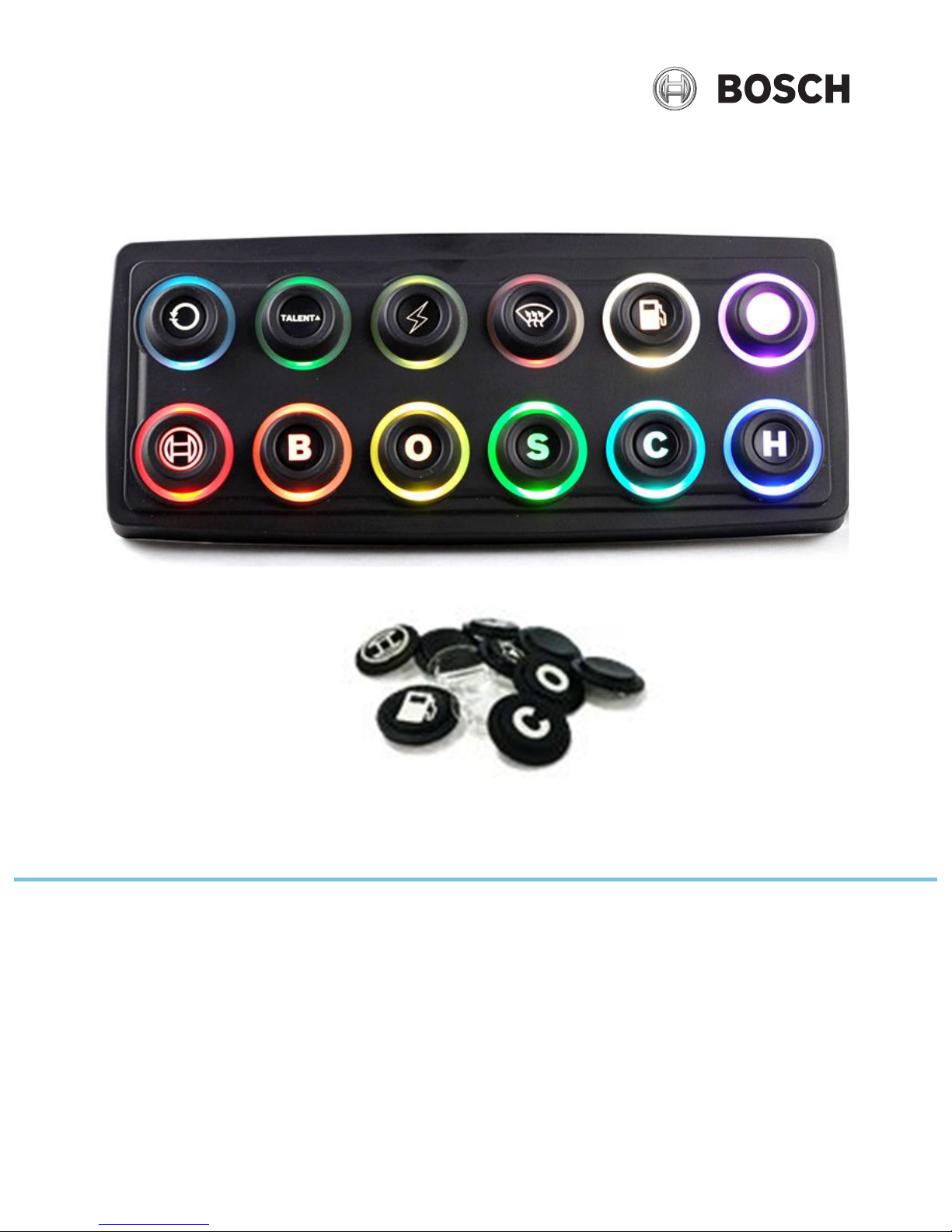
1 Introduction
The CAN Keypad CK-M12 allows for simplification of the dashboard by offering 12 buttons and
9 additional wired inputs to be evaluated and transmitted via CAN bus to other devices on the
bus. Each button has an individually addressable LED indicating ring that can be used to
acknowledge a button press event, indicate status of a device, or alert the driver to a fault
condition.
No special configuration software is needed, all feedback logic is done by PBX, DDU or ECU.

CAN Keypad CK-M12 Getting started | en 5
Bosch Motorsport Quick Start Manual 29.10.2019 | Version 1.1 |
2 Getting started
The following supplies are required to use the CK-M12:
– CK-M12
– Engine controller, data logger or related CAN enabled device
– Appropriate harnessing to connect all devices, note that the CK-M12 does not contain a
termination resistor.
These steps are recommended to get started with the CK-M12:
– Verify the resistance across CANH and CANL is equal to 60 ohms with a multimeter when
the system is powered off. If 60 ohms is not found, check the CAN termination and refer
to the wiring diagram in section three.
– Configure the CAN enabled device of choice to read the CAN messages from the CK-M12.
– Provide power to the CK-M12 and verify CAN communications between the CK-M12 and
CAN enabled device.
– Transmit indicator CAN messages for color and brightness to the CK-M12 and verify
response.
6 en | Wiring CAN Keypad CK-M12
29.10.2019 | Version 1.1 | Quick Start Manual Bosch Motorsport
3 Wiring
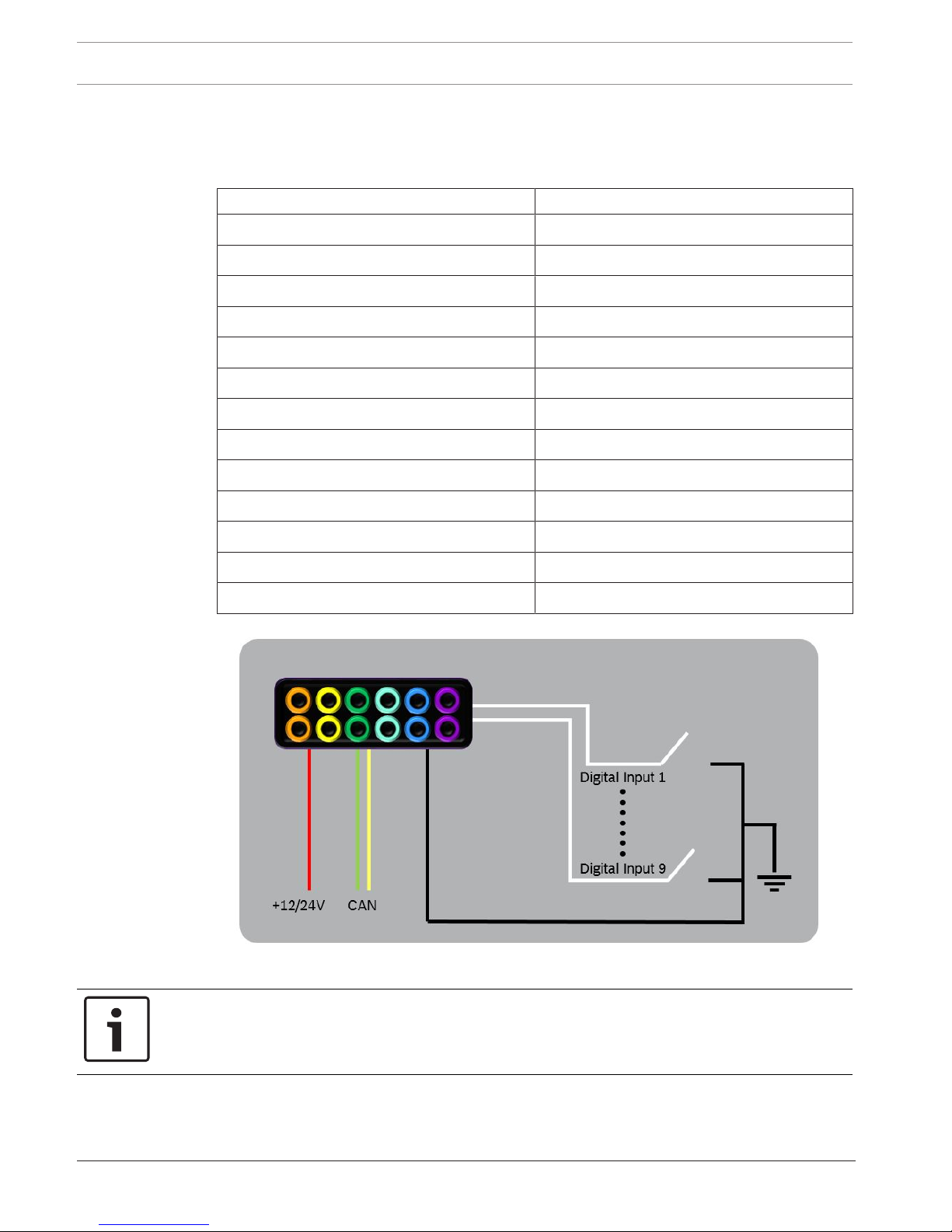
The following table lists descriptions for each wire of the CK-M12.
CK-M12 Wire Identification
Wire Function
Red 12/24V Power
Black Ground
Yellow CAN high (CANH)
Green CAN low (CANL)
White, Black Band Digital Input 1 Active Low
White, Brown Band Digital Input 2 Active Low
White, Red Band Digital Input 3 Active Low
White, Orange Band Digital Input 4 Active Low
White, Yellow Band Digital Input 5 Active Low
White, Green Band Digital Input 6 Active Low
White, Blue Band Digital Input 7 Active Low
White, Purple Band Digital Input 8 Active Low
White, Grey Band Digital Input 9 Active Low
Figure3.1: CK-M12 Wiring Concept
Notice!
Digital Inputs 1 to 9 are not intended to accept voltage! Additionally a maximum resistance
to ground of 100 Ohm must be respected for proper function of digital inputs.
CAN Keypad CK-M12 Wiring | en 7
Bosch Motorsport Quick Start Manual 29.10.2019 | Version 1.1 |
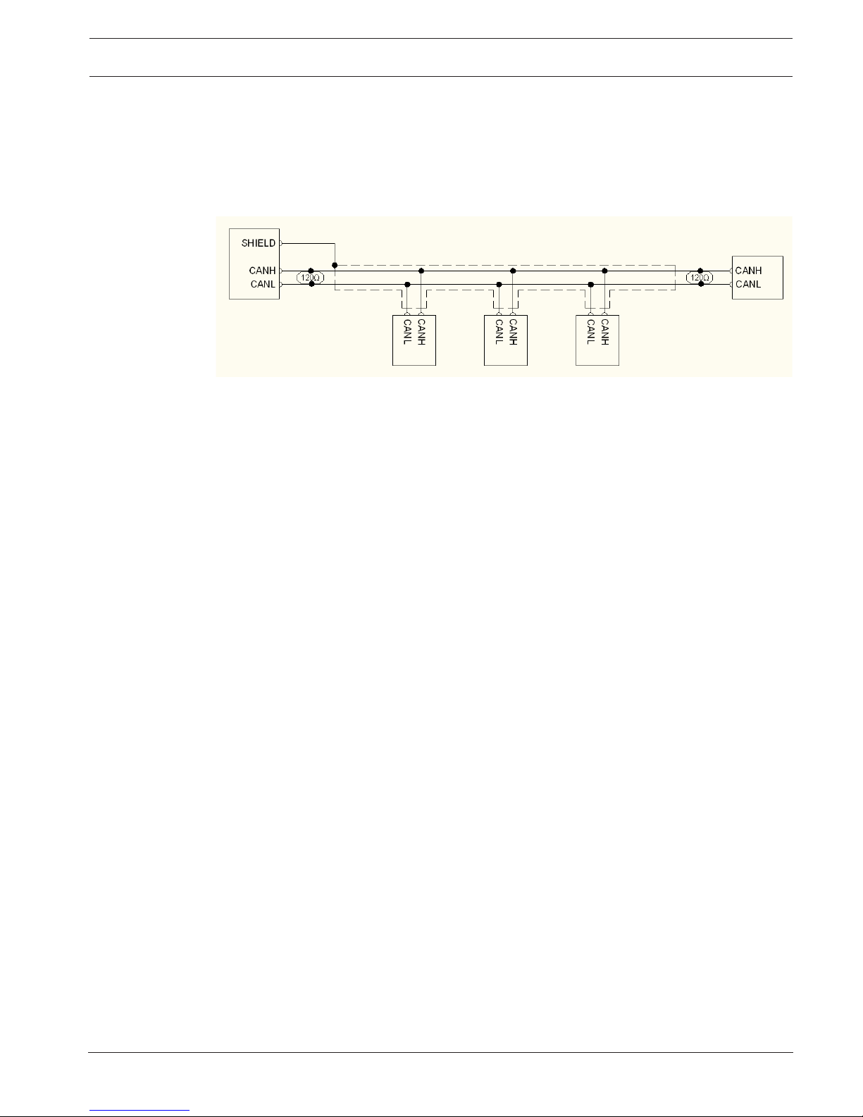
The CK-M12 Sport does not include CAN termination on board. Proper CAN termination must
be included in the wiring harness at each end of the bus. A daisy chain style bus must be
constructed with stub lengths for added devices kept to under 1 foot (0.3 meters). Figure 3
shows a correctly constructed CAN bus with termination. Shielding is not required and the CKM12 does not offer a shield wire. However, if another module on the CAN bus offers a shield
pin, it is recommended to use it.
Figure3.2: Example CAN bus with proper termination and shield concept
8 en | CK-M12 Sport Mounting and Environmental Considerations CAN Keypad CK-M12
29.10.2019 | Version 1.1 | Quick Start Manual Bosch Motorsport
4 CK-M12 Sport Mounting and Environmental
Considerations
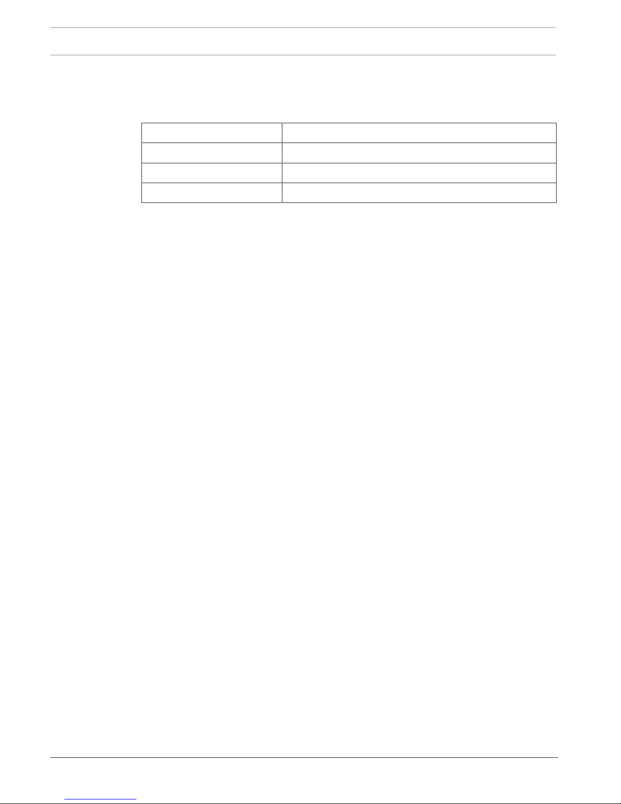
The following specifications should be considered for CK-M12 vehicle mounting.
Min. Temperature -40°C
Max. Temperature +85°C
Max. Vibration Bosch Motorsport Vibration Profile 1
Sealing Tightness IP68
 Loading...