

Page 1
CISS – Connected Industrial
Sensor Solution
Operating Instructions
Complies with
IMDA standards
DB101762
Page 2

2
Summary
1 About these operating instructions 3
1.1 Definition of special notices 3
1.2 Definition of general notices 3
2 Safety and environment 3
2.1 Radio frequency radiation exposure and further information 3
2.2 Disposal 3
3 Introduction and intended use 4
3.1 Intended use 4
3.2 Scope of delivery 4
4 Technical specification 5
4.1 Housing 5
4.2 Dimensions 5
4.3 Device specification 5
4.4 Sensors 6
4.5 Axial orientation of the sensors: accelerometer, gyroscope, magnetometer 6
4.6 Operating conditions 6
4.7 Measurement range 6
4.8 Accuracies 7
4.9 Resolution 7
4.10 Sampling rate 7
4.11 CISS – sensor description 8
4.12 LED indicators 11
4.13 Memory 11
4.14 Communication interfaces 11
5 First steps 12
5.1 Mounting the CISS 12
5.2 Connecting the CISS 13
5.3 Virtual CISS Demo App 13
5.4 Data transfer via USB – example Python script 18
5.5 Example system set up – using a gateway 21
6 General operation modes 22
6.1 General behaviour 22
6.2 Resetting the CISS 22
6.4 Streaming via USB 23
6.5 Streaming via BLE 23
6.6 Event detection mode 23
6.7 Time aggregation mode 24
7 Usage of the communication interfaces 24
8 Maintenance 24
9 Further Product Related Information 24
10 Regulatory and legal information about the CISS 25
10.1 European Union notices 25
10.2 USA: FCC notices 26
10.3 IMDA Singapore notices 26
10.4 ACMA Australia notices 26
10.5 China Notice 26
10.6 Japan Notice 26
10.7 Other certifications 27
10.8 Bluetooth® 27
10.9 Disposal 27
10.10 Restrictions of use 27
10.11 Open source license condition 27
Page 3
3
1 About these operating instructions
This document presents the CISS operating instructions, as well as detailed CISS sensor characteristics, communication
and management features through Bluetooth and USB communication.
This document refers to the CISS firmware version V02.03.00.
The latest firmware version and detailed instructions how to proceed are available at:
https://www.bosch-connectivity.com/media-and-downloads/
(CISS Firmware Update V.nn.nn.nn / CISS Firmware Update Operating Instructions).
Ensure that the CISS is working correctly by reading these instructions carefully before using the CISS in your planned
use case.
1.1 Definition of special notices
Warning: Indicates a hazard that could lead to minor or moderate injuries.
Always follow these instructions
Note: Points of emphasis and reminders of operational peculiarities for the device that could affect performance.
Always follow these instructions.
1.2 Definition of general notices
2 Safety and environment
Warning: Do not open the housing without authorization!
Opening the housing without authorization will void any warranty and includes risks of injury to the user.
Using the CISS according to its intended use and functionalities does not require the opening of the housing.
Do not open the housing.
2.1 Radio frequency radiation exposure and further information
The radiated output power of the device is far below the FCC radio frequency exposure limits. Nevertheless, the device
shall be used in such a manner that the potential for human contact during normal operation is minimized (see device
specification, chapter 4.3).
2.2 Disposal
Disposing of this product correctly will help save valuable resources and prevent any potential negative effects on human
health and the environment, which could otherwise arise from inappropriate waste handling. Please contact your local
authority for further details of your nearest designated collection point. Penalties may be applicable for incorrect disposal
of this waste, in accordance with your national legislation. For further information, please refer to chapter 9.5.
INFO: General information and instructions that must be followed
TIP: Practical advice
Page 4
4
3 Introduction and intended use
The CISS is a multi-sensor device detecting acceleration, angular velocity and magnetic fields, as well as environmental
conditions (temperature, humidity, light, air pressure, and noise). The robust housing and the small outline makes it
perfectly suitable for industrial retrofit applications, such as condition monitoring and predictive maintenance.
Configuring the device enables the user to address a broad variety of use cases, including interpreting the sensor data
by smart algorithms.
3.1 Intended use
The CISS operates according to the information provided in the operating instructions and the data sheet.
Validation and testing of any use or operation, which requires specific requirements and standards, which are not explicitly
mentioned in these documents, is the customer’s responsibility.
Please also see chapter 9.6 Restrictions of use.
Using the CISS with non-real-time operating systems (eg. Windows or Linux) might cause problems during the data
transmission. Increased utilisation of the target system might cause data loss or – in extreme cases - an interruption of
the data transfer.
3.2 Scope of delivery
CISS device
CISS cable
Mounting material (screws, washers, magnets)
Quick start guide
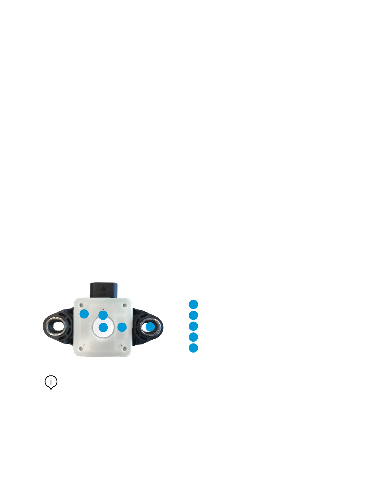
CISS: overview (back side)
2
3
4
5
1
1 Light Sensor
2
Status LEDs
3
Membrane (humidity measurement, pressure equalisation)
4
Power supply LED
5
Mounting holes
Note: Labels or stickers should not cover the membrane; otherwise, the humidity and pressure measurement
cannot be guaranteed within the specified performance.
Page 5
5
4 Technical specification
4.1 Housing
The CISS is built from a robust, industrially-suited housing with a suitable connector, that can be fixed at the housing via
a fixing bracket.
The compact design of the CISS fits perfectly in different industrial applications and also allows an easy and user-friendly
mounting in difficult to access environments.
For mounting instructions, please refer to chapter 5.1. Mounting the CISS.
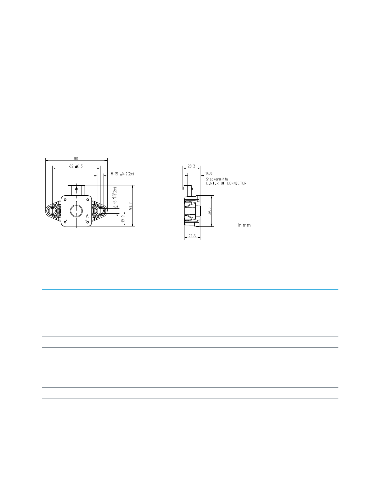
4.2 Dimensions
4.3 Device specification
ATTRIBUTE VALUE
Dimension Length 53.2 mm x Width 80.0 mm x Height 21.3 mm
Weight Ciss Device: 34 g
Cable: 60 g
Fastening set (2magnets, 2 screws, 2 washers): 19g
Power supply 5V DC
Enclosure protection class IP 54
Sampling rate (selectable) Depending on the selection of sensor settings (Inertial sensors: ≤100 Hz /
special mode accelerometer: 2 kHz; environmental sensors: ≤1 Hz)
Memory capacity (user data memory) 2MB
Communication BLE 4.0 / USB 2.0
Bluetooth frequency band 2400 – 2483.5 MHz
Transmission power (Bluetooth) 0 dBm
Page 6
6
4.4 Sensors
INERTIAL SENSORS ENVIRONMENTAL SENSORS
Accelerometer (3-axis) Temperature
Gyroscope (3-axis) Humidity
Magnetometer (3-axis) Light
Pressure
Microphone
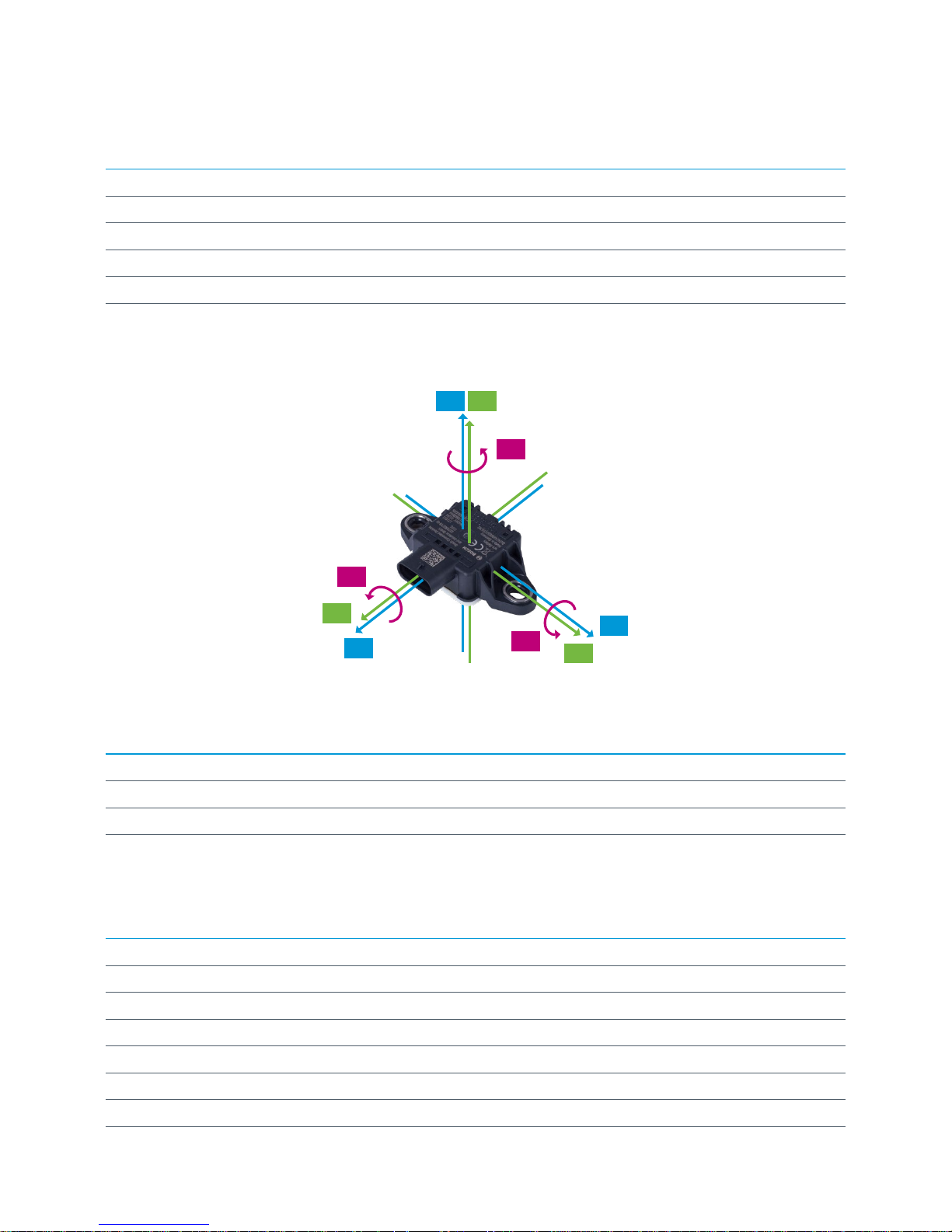
4.5 Axial orientation of the sensors: accelerometer, gyroscope, magnetometer
Legend:
aX, aY, aZ = accelerometer vector
mX, mY, mZ = magnetometer vector
gX, gY, gZ = gyroscope vector
mZ aZ
mX
aX
mY
aY
gZ
gX
gY
4.6 Operating conditions
ATTRIBUTE RANGE
Operating temperature range -20 – 80 °C
Humidity range 10 – 90 % relative humidity (non-condensing)
Pressure range 300 – 1100 hPa
4.7 Measurement range
SENSOR RANGE
Accelerometer ± 2, 4, 8, 16g (16 bit resolution)
Gyroscope ± 2000 °/s
Magnetometer ±1300 μT (x,y-axis); ±2500μT (z-axis)
Temperature -20 – 80 °C
Humidity 20 – 90 % r.H. (non-condensing)
Pressure 300 – 1100 hPa
Light 0 – 2112800 Lux
Page 7

7
4.8 Accuracies
SENSOR ACCURACY
Accelerometer
(zero-g offset (over life-time))
± 50 mg
Gyroscope (zero-g offset (over life-time)) ± 1 °/s
Magnetometer 0.06 × M ± 25 μT (M= real magnetic field)
Temperature max. ± 2 °C + 3% T °C
Humidity (at 20 – 80 % relative humidity) max. ± 7% at +20 °C
max. ±10% at -20 °C
Pressure (at 25 °C and 40 % relative
humidity (standard deviation))
± 1.5 hPa
Light (at 538 nm wavelength, 25° C
ambient temperature)
± 15 %
4.9 Resolution
SENSOR RESOLUTION
Accelerometer 1mg (± 2, 4, 8, 16g)
Gyroscope 1 °/s
Magnetometer 1.0 µT
Temperature 0.1 °C
Humidity 0.01 % relative humidity (r.H.)
Pressure 0.01 hPa
Light 1 Lux
4.10 Sampling rate
SENSOR SAMPLING RATE BLUETOOTH SAMPLING RATE USB
Inertial sensors (accelerometer,
gyroscope, magnetometer)
≤100 Hz ≤100 Hz
accelerometer: 2 kHz
(see INFO box below)
Environmental sensors (temperature,
humidity, pressure, light, microphone)
≤1 Hz ≤1 Hz
Note: The maximum sampling rate of the accelerometer is 2 kHz. If the sampling rate of 2 kHz is selected, all other
sensors are automatically deactivated. The operating range: sampling rate > 100 Hz and < 2kHz is not specified.
Page 8

8
4.11 CISS – sensor description
4.11.1 Accelerometer: 3-axis acceleration sensor – BMA280
Acceleration range ± 2, ± 4, ± 8, ± 16 g (default)
Accuracy (zero-g offset (typical, over
life-time))
± 50 mg
Resolution 1 mg
Noise density (typical) 120 µg x Hz
-1/2
Bandwidths 8 – 10 Hz
Sampling rate BLE: ≤ 100 Hz
USB: ≤ 100 Hz; special mode 2 kHz
Precision (at ± 16 g resolution) ± 5 mg
4.11.2 Gyroscope: 3-axis angular velocity sensor – BMG16
Measurement range ± 2000 °/s
Accuracy (zero-g offset (typical, over
life-time))
± 1 °/s
Resolution 1 °/s
Zero-rate offset over temperature 0.015 °/s x K
-1
Noise density (typical) 0.014 °/s x Hz
-1/2
Sampling rate BLE: ≤ 100 Hz
USB: ≤ 100 Hz
Precision ± 0.50 °/s
4.11.3 Magnetometer: 3-axis magnetometer – BMC150
Measurement range ± 1300 µT (x-, y-axis)
± 2500 µT (z-axis)
Accuracy 0.06 × M ± 25 μT
(M= real magnetic field)
Resolution 1.0 µT
Precision (1-sigma level) ± 2.5 μT
Sampling rate BLE: ≤ 100 Hz
USB: ≤ 100 Hz
Page 9

9
4.11.4 Environmental sensors - temperature, pressure, relative humidity – BME280
For the environmental measurands - temperature, relative humidity and air pressure - a BME280 is used. With the influence
of the housing and self-heating of the electronic components, the behavior given in the table below has been characterized
for the CISS. The given accuracy is specified with the following measurement setup:
One environmental measurement per minute
No accelerometer, magnetometer, gyroscope active
Power supply via the CISS USB cable
TEMPERATURE
Range -20 – 80 °C
Resolution 0.1 °C
Precision ± 0.1 °C
Response time (τ
63 %
) from 20 °C to 50 °C
at 40 % r.H. and 980 hPa (with medium
access)
7.5 minutes
Accuracy max. ± 2 °C +3% T °C
Sampling rate BLE / UBS: ≤ 1 Hz
PRESSURE
Range 300 – 1100 hPa
Resolution 0.01 hPa
Precision (1-sigma level) ± 0.01 hPa
Response time < 1 s
Accuracy at 25 °C and 40 % r.H. ± 1.5 hPa
Sampling rate BLE / UBS: ≤ 1 Hz
HUMIDITY
Range 0 – 90 % r.H.
Resolution 0.01 % r.H.
Precision (1-sigma level) ± 0.5 % r.H.
Response time (τ
63 %
) from 80 % r.H. to 40
% r.H. at 25 °C and 980 hPa
20 minutes
Accuracy at 20 – 80 % r.H. max. ± 7% at +20 °C
max. ±10% at -20 °C
Sampling rate BLE / UBS: ≤ 1 Hz
Page 10

10
4.11.5 Microphone - AKU340
The CISS contains the microphone AKU340.
The CISS housing, with its membrane, is not optimized for sound measurements, only the noise level is determined and sent
by the CISS firmware.
Directivity Omni-directional
Frequency response ±3 dB 60 Hz – 12.5 kHz
Signal-to-noise ratio 62 dB
Tolerance at -38 dB ± 2 dB
Sampling rate BLE: ≤ 1 Hz
Note: Access to the microphone is only via BLE possible.
4.11.6 Ambient light sensor - MAX44009
The surrounding illumination can be measured with the light sensor MAX44009. It is located beneath the white cover of the
CISS. The adapted measurement parameters inside the housing are given in the table below:
Dynamic range 0– 2112800 Lux
Maximum resolution 1 Lux
Maximum integration time at low light 800 ms
Accuracy at 538 nm wavelength,
25 °C ambient temperature
15%
Sampling rate BLE / UBS: ≤ 1 Hz
Page 11

11
4.12 LED indicators
The CISS printed circuit board (PCB) includes LEDs, which indicate various states.
The LEDs on the back side of the CISS indicate the following:
Flashing LEDs
Yellow: The Bluetooth radio is advertising
Orange: The Bluetooth connection is established
Red: The CISS firmware is running
Red: This LED is used for Bosch-internal testing and can be ignored by the user
(only for CISS w/o battery with production date 2017).
INFO: The measurement of the illumination is not influenced by the flashing LEDs.
4.13 Memory
The CISS contains a 2 MB user data memory, which is accessible as a mass storage device over USB. It is used for local
logging of measurement data.
4.14 Communication interfaces
The CISS includes two communication interfaces - Bluetooth Low Energy (BLE) and Universal Serial Bus (USB) described
in the following.
The protocols and data formats are described in chapter 7.
BLE
Currently, Bluetooth Low Energy V4.0 is supported with the CISS always acting as a peripheral device, to which other BLE
devices like smartphones, tablets, etc. can establish a connection.
The Bluetooth communication interface is used, e.g. by a gateway or a mobile app, to:
Configure the CISS
Transfer data
USB
The USB communication is established via the USB cable (scope of delivery) and the connector at the CISS housing.
The cable is supplied with a standard USB A connector on one end and the CISS connector
(4way 1.2 SealStar FA Connector 805-122-541) at the other end.
Page 12

12
INFO: PIN configuration CISS connector (4way 1.2 SealStar FA Connector 805-122-541)
1 – USB_VBUS
2 – UBS_DP
3 – UBS_DM
4 – GND
The CISS microcontroller is a USB 2.0 full speed capable device.
The USB interface is used for:
Power supply (5V USB port)
Configuration of the CISS
Data transfer
INFO: Please find the communication protocols for BLE (CISS BLE Communication Protocol)
and USB (CISS USB Communication Protocol) as separate documents at:
www.bosch-connectivity.com/media-and-downloads/.
5 First steps
5.1 Mounting the CISS
For mounting, the CISS housing has two side brackets. These can be used with screws (direct mounting) or with screws and
magnets (magnetic mounting). The scope of delivery contains:
Magnets
Washers
Screws
for mounting the CISS with the black side on top.
Direct mounting Magnetic mounting
Note: The use of the mounting magnets influences the measurements of magnetic fields.
The mounting magnets should not be used if the magnetometer is activated.
INFO: Please fix the provided screws (M4 x 8) hand-tightend via a 2.5 hexagon socket screwdriver. Depending
on the target mounting place, the provided screws might not fit - please use appropriate screws for target.
Page 13

13
5.2 Connecting the CISS
Connect the USB cable, included in the scope of delivery, to the CISS and to a USB power supply (USB power supply,
USB port of PC, etc.).
Close the securing bracket.
CISS is now ready to be put into operation.
5.3 Virtual CISS Demo App
1. Download and install the “Virtual CISS App” (Apple App Store / Google Play Store)
2. Ensure that Bluetooth is activated on the device you want the CISS to connect with (smartphone, tablet etc.)
3. Start the “Virtual CISS App”
4. After the start screens you get a short overview of the most important functions via the help screens.
INFO: The help screens, fitting to the area you are at that moment, are accessible at any time.
Page 14

14
5. At the start of the App the search button is shown. Click on the search-button to find devices.
6. Choose your CISS by tapping on the CISS device from the listed devices to establish the connection between
the CISS device and the smartphone / tablet.
Page 15

15
7. Tap on the settings icon
8. To ensure an easy identification of your devices, please rename your CISS by tapping on the pencil and typing
in your preferred name. Tap on rename.
INFO: The battery life is only relevant, if a CISS version with battery will be launched.
After the renaming, you have to wait for 5–10 sec. Afterwards you have to establish the connection again.
Page 16

16
9. Tap on the setting icon to select the sensors based on your requirements and adapt the corresponding sampling rate.
10. Tap on the streaming button to start streaming the measured data. The data is shown under the respective sensor icon.
11. Tap on the chart icon
Page 17

17
12. Select the sensors you want to see in the chart by taping on the sensor icons.
The graphs and the values become displayed.
Options using the chart view
a. Refresh: If the chart is zoomed by the user, click on this icon to recover the original view.
b. Enable / disable the scrolling of the visible window to show all X values in the graph
c. Enable / disable auto scale of the y axis of the graph
d. Play / stop: tap on to button to show streaming data in the graph / to freeze streaming data in the graph
Page 18

18
Summary
e. See the help screens, fitting to the area you are now.
f. Disconnect: Click on the disconnect icon, if you want to disconnect your device
g. Rename your device, select your sensors, adapt your sampling rates
h. Start / stop data streaming
i. Show the streamed data in a chart
5.4 Data transfer via USB – example Python script
A Python script is provided in order to quickly start using the CISS. This Python script is an example for the integration of
the CISS within an (gateway) environment.
It can be used for evaluation purposes as well as a starting point for your own integration activities.
Data streaming
Parameter settings, Firmware updates
Energy
USB USB
Proprietary
serial communication
Page 19

19
Requirements
Host computer running on Linux Kernel version 2.6 or later or Windows 7 or later.
INFO: For support regarding your Linux version, please contact you Linux distributor.
A Python 2.7 environment installed on your host computer.
Ensure that the following modules are installed within your Python 2.7 environment
Serial (use the last version of pyserial: pyserial 3.4 (https://pypi.python.org/pypi/pyserial))
Signal, Config Parser, Csv, Time, Os (in Python installer 2.7.14 included)
Driver
In case you are using Windows 7 or Windows 8, please download and install the CISS driver for Windows.
INFO: The Windows 7 / 8 driver is available at www.bosch-connectivity.com/media-and-downloads/
(CISS Driver Installer Windows).
For more information regarding the installation of the driver for Windows 7 and Windows 8 and for more
details about why it is not needed for Windows 10 and Linux, you find an additional document at:
www.bosch-connectivity.com/media-and-downloads/ (CISS Driver Installer Windows Operating Instructions)
There is no need to install this driver for Windows 10 or Linux environments.
Example Python script
Download the example Python script.
INFO: The example Python script is available at www.bosch-connectivity.com/media-and-downloads/
(CISS Demo Scripts Python)
A user guide for the Python script is available at www.bosch-connectivity.com/media-and-downloads/
(CISS Demo Scripts Python Operating Instructions)
Page 20

20
Configure the CISS
Included in the example Python script download package there is a file named: sensor.ini
TIP: If the sensor.ini file is lost, run the script once, a default sensor.ini file will be created.
Open the sensor.ini file
The following figure shows a screenshot of the sensor.ini file, to give an overview over the functions and settings.
The grey marked area shows the settings for the inertial sensors.
The green marked area shows the settings for the environmental sensors.
The numbers are explained below the figure.
(1) Adjust the serial interface (e.g., “COM81” for Windows environments or “/dev/ttyACM0” for Linux environments)
Adjust the settings for the sensors like shown in the example for the accelerometer
(2) Activate / deactivate the streaming mode
(3) Activate / deactivate the event mode.
If the event mode is activated, put the threshold you need for your requirements. Each cross of the threshold will be
detected. The thresholds must be in the range of the individual sensors, see section 4.11.”
INFO: It is not possible to activate the streaming mode and the event mode for one sensor at the same time.
Only one threshold is possible, it is not possible to add a range (between two thresholds).
(4) Choose a measurement range for the accelerometer: ±2, 4, 8, 16 g (16-bit resolution)
(5) Choose the sampling rate for all inertial sensors. The example Python script uses the unit µs.
HZ MILLISECOND MICROSECOND
1 1000 1000000
10 100 100000
100 10 10000
1000 1 1000
2000 0.5 500
T (µs) = 1 / f(Hz) * 1000 *1000
Page 21

21
Please respect the sampling rates of the sensors when choosing the sampling rate in the settings of the sensor.ini file
(see chapter 4.10. Sampling rate).
Data transfer
Start the example Python script via the command shell (Windows cmd.exe; Linux e.g. bash).
The data the CISS measures will be logged in .csv format in the output data file named: datastream.csv.
Default: The file will be saved in the same place where the example Python script is saved.
INFO: For more information regarding the example Python script (handling and further development),
please find a separate documentation at: www.bosch-connectivity.com/media-and-downloads/
(CISS Demo Scripts Python Operating Instructions)
5.5 Example system set up – using a gateway
The figure shows an example setup of the CISS attached to a gateway, which is part of an IP network. A database for storage
of measured data as well as a user interface are located on a server in the network.
This setup is suitable for streaming and event detection use cases, where the CISS continuously sends measurement data
through its communication interface.
Instead of the gateway any other USB host or BLE central device (e.g. computer, smartphone) could be deployed for local
visualization.
Gateway
User Interface
Data streaming
Parameter settings, Firmware updates
Energy
Data streaming
Parameter settings
Energy
USB
USB USB Power supply
BLE BLE
USB
Proprietary
serial communication
Network
LAN
Wifi
LAN
Wifi
Database
Backend
Page 22

22
6 General operation modes
In this chapter, the behavior of the operation modes is described. For information on how to configure the CISS or how to
receive data from it, please refer to Chapter 7.
6.1 General behaviour
The individual sensors in the CISS can be activated / deactivated for measurements.
Additionally, different sampling rates can be given for the inertial sensors and the environmental sensors.
The sensors within the CISS are grouped into two clusters:
The first cluster comprises the inertial measurands (acceleration, angular velocity, magnetic field). Besides the sampling
rate, which applies to all inertial sensors, each sensor can be configured individually.
The second cluster is comprised of all environmental sensors (temperature, humidity, pressure, light, noise).
Equally, the sampling rate applies to all sensors, while each sensor can be activated or deactivated individually.
The reporting of the results is structured accordingly.
6.2 Resetting the CISS
The integrated microcontroller of a CISS performs a reset when it is detached from a USB host or power supply or it gets
unmounted (e.g. with the “unmount” command in a Linux-system).
The CISS settings will be reset, the logged data will be preserved.
Note: Exception: Disabling the 2 kHz acceleration streaming mode will cause a reset.
6.3 Logging data to the local memory
When the CISS is configured to log measurements to its local memory, a file will be created in the user data memory,
that is accessible as a mass storage device over USB.
If the local memory is full, the logging will be stopped.
It is possible to concurrently log to memory and stream data via BLE.
The time, until the memory is full, depends on the settings of the CISS.
Example 1:
Sensors: All sensors activated
Sampling rate inertial sensors: 0,01 sec
Sampling rate environmental sensors: 60 sec
Allows logging for approx. 6 min
Example 2:
Sensors: Acceleration sensor and environmental sensors activated
Sampling rate inertial sensors: 0,01 sec
Sampling rate environmental sensors: 60 sec
Allows logging for approx. 10 min
Page 23

23
The format of the log file is an ASCII-file, with comma separated values (filename: log<time>.csv). The filename corresponds
to the time counter in the microcontroller at the beginning of the measurement. In the file, the first three lines contain header
information on the measurement. This includes a comma-separated list of the selected measuring dimensions, e.g.:
Time(ms),ax,ay,az,gx,gy,gz,mx,my,mz,Temp,Humidity,Pressure,Light,Noise
After this line, the measurements are given according to the defined columns. If present, inertial and environmental lines are
interleaved according to the sampling intervals.
Each line always contains all columns (i.e. the number of commas per line is constant). Each sensor has its own line and
column.
The CISS microcontroller has an internal time counter which is used for the timestamp when logging to the local memory.
Per default, this counter starts at zero after a power cycle. To get an absolute time, the counter may be set to a UNIX
timestamp through the corresponding USB or BLE commands (see Chapter 7).
6.4 Streaming via USB
When streaming over USB, the measurements from the sensors in the CISS are offered through a virtual serial port (virtual
COM port 115kBaud 8N1) continuously. The configuration commands as well as the data format of the streamed sensor
measurements are described in Chapter 7.
With this mode, it is possible to use the maximum sampling frequency of 2 kHz for the 3-axis accelerometer with a special
configuration. In this case, only the accelerometer is enabled.
Note: Access to the noise measurement data is only available via BLE.
6.5 Streaming via BLE
The CISS per default acts as a Bluetooth Low Energy (BLE) advertiser. This means that another BLE device may detect the
CISS when scanning for devices and is able to initiate a connection.
Using BLE, it is possible to configure a CISS and continuously receive measurement data from it.
For details on the available Bluetooth characteristics, please refer to Chapter 7. It is possible to concurrently stream data
via BLE and log to memory.
INFO: It is not possible to use the special mode of the accelerometer (sampling rate = 2 kHz)
when streaming via BLE.
6.6 Event detection mode
In the event detection mode, the user is able to define thresholds for one or multiple sensor signals of the CISS.
Each time the respective measurement signal crosses the threshold level, an event is generated and signaled via USB / BLE.
The event message contains the direction of the threshold crossing, i.e. if the signal was below the threshold and goes above
or vice-versa (termed overshoot/undershoot), see Chapter 7.
INFO: Each sensor has the possibility to set only one threshold. The possibility to set a threshold range
is not implemented, yet.
Page 24

24
6.7 Time aggregation mode
The time aggregation mode is a special USB streaming mode, which reduces the frame rate compared to the sampling rate of
the sensors. Measurements are aggregated in time frames and then the minimum, maximum, mean and standard deviation
of these time frames are reported.
Currently, the CISS contains a fixed configuration for the time aggregation mode:
Acceleration & angular velocity, sampling rate 100Hz, time frame 2s
Temperature, sampling rate 1Hz, time frame 10s
See chapter 7 for the format of the signaled USB messages.
INFO: When entering the time aggregation mode, the BLE functionality of the CISS is completely
switched-off (i.e. the CISS will no longer advertise).
7 Usage of the communication interfaces
For a detailed description regarding the communication interfaces, please refer to the following documents:
CISS BLE Communication Protocol
CISS USB Communication Protocol
These documents are available at: www.bosch-connectivity.com/media-and-downloads
8 Maintenance
Warning: Damage to materials can cause risk of fire!
Liquid which enters the device can cause short circuits and damage the device.
This could cause fire, data loss and incorrect measurements.
9 Further Product Related Information
Please find all product related documents and user guides on our website:
www.bosch-connectivity.com/media-and-downloads
Please click on “Load more” to see all available documents.
Page 25

25
10 Regulatory and legal information about the CISS
Accompanying information
Radio power: 2 mW (peak conducted)
Frequency band: 2400 – 2483.5 MHz
10.1 European Union notices
European Union notices
Radio Equipment Directive
Hereby, Bosch Connected Devices and Solutions GmbH declares that the radio equipment type “CISS“ is in compliance
with Directive 2014/53/EU (Radio Equipment Directive). The full text of the EU declaration of conformity is available at the
following internet address: www.bosch-connectivity.com/media-and-downloads/ (CISS Declaration of Conformity).
RoHS
The CISS meets the requirements of the Directive 2011/65/EU on the restriction of the use of certain hazardous substances
in electrical and electronic equipment (RoHS Directive).
Page 26

26
REACH
The CISS meets the requirements of the Directive 1907/2006 (REACH Directive) and does not contain substances of very
high concern as specified in the REACH Directive in concentrations which require notification.
10.2 USA: FCC notices
FCC has issued an EQUIPMENT AUTHORIZATION to Bosch Connected Devices and Solutions GmbH for CISS according to
FCC rule parts 15 C with the FCC ID: 2ADSJCISS
Note: Changes or modifications not expressly approved by Bosch Connected Devices and Solutions GmbH could
void the FCC certificate and therefore user‘s authority to operate the equipment.”
Note: This equipment has been tested and found to comply with the limits for a Class B digital device, pursuant to
Part 15 of the FCC Rules. These limits are designed to provide reasonable protection against harmful interference
in a residential installation. This equipment generates, uses and can radiate radio frequency energy and, if not
installed and used in accordance with the instructions, may cause harmful interference to radio communications.
However, there is no guarantee that interference will not occur in a particular installation. If this equipment does
cause harmful interference to radio or television reception, which can be determined by turning the equipment off
and on, the user is encouraged to try to correct the interference by one or more of the following measures:
Reorient or relocate the receiving antenna.
Increase the separation between the equipment and receiver.
Connect the equipment into an outlet on a circuit different from that to which the receiver is connected.
Consult the dealer or an experienced radio/TV technician for help.
10.3 IMDA Singapore notices
The CISS has been registered with the Info-communications Media Development Authority under regulation 20(6) of the
telecommunications (Dealers) regulations (Cap 323, Rg 6) and approved for sale in Singapore under Dealer’s License
DB101762.
10.4 ACMA Australia notices
This device complies with the requirements of the relevant ACMA Standards made under the Radiocommunications Act 1992
and the Telecommunications Act 1997.
10.5 China Notice
This device has passed the type approval by SRRC and has been granted the CMIIT ID: 2018DJ2794
10.6 Japan Notice
This device is granted pursuant to the Japanese Radio Law (電波法). This device should not be modified (otherwise the
granted designation number will become invalid)
Page 27

27
10.7 Other certifications
The CISS is certified for operation in the European Union, the U.S.A., Singapore, Australia and China.
The certification for the European Union only applies to CISS devices with the CE printed on the housing. The
user shall verify before using the CISS in the European Union.
The certification for the United States of America only applies to CISS devices with the FCC ID printed on the
housing. The user shall verify before using the CISS in the United States of America.
The certification for Australia only applies to CISS devices with the ACME Lable printed on the packaging or on
the housing. The user shall verify before using the CISS in Australia.
The certification for China only applies to CISS devices with the CMIIT ID printed on the housing. The user shall
verify before using the CISS in China.
The certification for Singapore only applies to CISS devices with the IDMA mark on the housing or with the
“Complies with IMDA standards DB101762” notification printed on the Front page of the “Quick Start Guide” /
“Operating Instructions”. The user shall verify before using the CISS in Singapore.
Use of the CISS is subject to validation and observation of local legal regulation by the customer. For information on other
certifications – which gradually may be issued over time – please, contact our CISS support at support@bosch-connectivity.com.
10.8 Bluetooth®
The CISS has been granted the Bluetooth® listing by the BT-SIG.
10.9 Disposal
The unit, accessories and packaging should be sorted for environmental-friendly recycling. Do not dispose of the device into
household and industrial waste!
According to the European Guideline 2012/19/EU, electric and electronic devices that are no longer usable must be collec-
ted separately and disposed of in an environmentally correct manner.
10.10 Restrictions of use
CISS housing is not to be opened or tampered with. CISS is designed for use within environmental conditions as further
detailed in this operating instructions. It is the customer’s responsibility to validate and test any use or operation under
deviating environmental conditions.
Neither the CISS nor a potential product derivation, are designed, intended, or authorized for use as components in systems
intended for surgical implant into the body, or other applications intended to support or sustain life, or for any other application in which the failure of the Bosch product could create a situation where personal injury or death may occur. The same
applies for any kind of weapon, or any device or application which is potentially dangerous for human life.
The CISS is designed for monitoring purposes and shall not be used as an element of control and safety in machines under
the scope of the Machinery Directive 2006/42/EC.
Bosch Connected Devices and Solutions GmbH shall not be held liable for any damages resulting from any use of the CISS
outside/beyond the certified types of operation and/or defined field of application.
10.11 Open source license condition
The CISS embedded software contains open source software (OSS) components.
The OSS copyrights and license conditions are provided in the file “DataStreamer_v02.01.01_FOSS_Disclaimer.txt” which
can be read after connection of the CISS via USB as a mass storage device to your PC.
For further assistance, please refer to http://www.bosch-connectivity.com/CISS
or e-mail to: support@bosch-connectivity.com
Page 28

Ludwig-Erhard-Straße 2
72760 Reutlingen
Germany
support@bosch-connectivity.com
Postfach 1342
72703 Reutlingen
Germany
www.bosch-connectivity.com
Bosch Connected Devices and Solutions GmbH
 Loading...