

Bosch CHP CE 400 NE, CHP CE 1200 NE, CHP CE 600 NE, CHP CE 800 NE, CHP CE 1287 NE Technical Manual
...
Technical guide
System solution
4-draught steam boiler and CHP
with MEC system
6 720 885 509 (2018/03) GB

Contents
Systemlösung – 6 720 885 509 (2018/03)
2
Contents
1 System solution: 4-draught steam boiler with
combined heat and power (CHP) . . . . . . . . . . . . 3
1.1 Notice on technical guide . . . . . . . . . . . . . 3
1.2 System solution . . . . . . . . . . . . . . . . . . . . . 3
1.3 Features and benefits . . . . . . . . . . . . . . . . 4
2 System components . . . . . . . . . . . . . . . . . . . . . . 5
2.1 General . . . . . . . . . . . . . . . . . . . . . . . . . . . 5
2.2 Bosch CHP for external waste heat use . . 6
2.2.1 Description CHP CE ... NE . . . . . . . . . . . . . 6
2.2.2 Technical data . . . . . . . . . . . . . . . . . . . . . . 7
2.2.3 Operation conditions CHP . . . . . . . . . . . . 8
2.3 4-draught boiler system . . . . . . . . . . . . . . 9
2.3.1 Description of 4-draught boiler system . . . 9
2.3.2 Technical data . . . . . . . . . . . . . . . . . . . . . 10
2.3.3 Dimensions and connections . . . . . . . . . 11
2.4 MEC System – overview . . . . . . . . . . . . . 13
2.5 Further options for waste heat use/peak
load boiler . . . . . . . . . . . . . . . . . . . . . . . . 14
2.5.1 Waste heat boiler HRSB . . . . . . . . . . . . . 14
2.5.2 3-draught waste heat boiler for use
of waste heat only . . . . . . . . . . . . . . . . . . 15
2.5.3 System extension with peak load boiler . 15
3 Engineering information and sizing . . . . . . . . . 16
3.1 Basic principles . . . . . . . . . . . . . . . . . . . . 16
3.1.1 Economic viability . . . . . . . . . . . . . . . . . . 16
3.1.2 Economic general conditions . . . . . . . . . 16
3.1.3 Technical system data . . . . . . . . . . . . . . . 17
3.2 Pre-dimensioning . . . . . . . . . . . . . . . . . . 18
3.2.1 Estimate design of key components . . . . 18
3.2.2 Investment costs . . . . . . . . . . . . . . . . . . . 18
3.2.3 Evaluation of economic viability . . . . . . . 19
3.2.4 Integration of 4-draught steam boiler . . . 20
3.3 Sizing of key components . . . . . . . . . . . . 23
3.3.1 Sizing of 4-draught steam boiler . . . . . . . 23
3.3.2 Sizing of CHP module . . . . . . . . . . . . . . . 24
3.3.3 Steam amount/waste heat output
and CHP/boiler combinations . . . . . . . . . 24
3.3.4 Demand for useful energy for
make-up water preheating, heating
energy and DHW . . . . . . . . . . . . . . . . . . . 28
3.3.5 Safety equipment . . . . . . . . . . . . . . . . . . 30
3.3.6 System control . . . . . . . . . . . . . . . . . . . . 30
3.3.7 Flue system . . . . . . . . . . . . . . . . . . . . . . . 32
3.4 System design . . . . . . . . . . . . . . . . . . . . . 34
3.4.1 Hydraulics with bypass . . . . . . . . . . . . . 34
3.4.2 Hydraulics without bypass . . . . . . . . . . . 36
3.4.3 Installation . . . . . . . . . . . . . . . . . . . . . . . 38
4 Appendix . . . . . . . . . . . . . . . . . . . . . . . . . . . . . . 40
4.1 List of components . . . . . . . . . . . . . . . . . 40
4.2 Further technical documents . . . . . . . . . . 41
Keyword index . . . . . . . . . . . . . . . . . . . . . . . . . . 42

System solution: 4-draught steam boiler with combined heat and power (CHP)
3
Systemlösung – 6 720 885 509 (2018/03)
1 System solution: 4-draught steam boiler with combined heat and power (CHP)
On the background of increasingly scarce natural
resources, sharp increases in energy prices over the last
few years and a turnaround in energy policy, it has
become indispensable, not only from an ecological, but
also from an economic point of view, to review and
reduce one's own energy consumption.
The industrial sector, the most energy-demanding of the
economic sectors, provides a large savings potential.
Often industrial applications require a steam supply
system. Such a system can be optimised concerning
energy consumption and economic viability by using
combined heat and power (CHP) in combination with a
CHP module. In the context of a turnaround in energy
policy, CHP plays a very important role. Its part in the
power generation mix in Germany will increase until
2020 to 25 %.
1.1 Notice on technical guide
The existing technical guide “4-draught boiler and CHP
with MEC system” can be used as information to simplify
the planning and sizing of 4-draught steam boiler system
in combination with combined heat and power unit by
Bosch.
The technical guide shall help you to understand the
basics for using flue gas heat for creating steam in 4draught steam boilers and for designing the components
of a boiler system in conjunction with a combined heat
and power unit (CHP).
The existing technical guide will show possible ways of
execution and respond to open questions concerning
planning, calculation, economic viability and quotation.
1.2 System solution
For commercial and industrial applications, the use of a
CHP system in conjunction with a steam boiler with
integrated waste heat use can be an efficient alternative.
Here, the CHP unit (design as CHP module for external
flue gas use) creates electrical current. A downstream
boiler system uses the hot flue gases of the CHP for
efficient creation of process vapour. The motor heat of
the CHP module can be used for make-up water
preheating, for heating or for DHW heating.
The steam boiler with waste heat utilisation is a
conventionally fired 3-draught steam boiler with
integrated additional fourth draught (4-draught steam
boiler). The hot flue gas of the CHP module is led
through the boiler to support steam production. Thanks
to the integrated combustion in 4-draught steam boilers,
steam peak load boilers are not necessary here that are
usually required with pure waste heat boilers.
Investment costs, space requirements and equipment
effort can be reduced significantly.
The use of a CHP in combination with a 4-draught steam
boiler is gently on the environment in more than one
respect.
The most important aspect is the considerably lower
consumption of primary energy compared to
conventional, separated production of current, steam
and heat. With a CHP, natural resources are saved and
the environment is protected from pollutants from other
combustion processes.
For the combination of a 4-draught steam boiler series
UL-S by Bosch Industriekessel GmbH and a CHP system
by Bosch KWK Systeme GmbH, different system
hydraulics are proposed in this document and their
planning and execution is described (Æ chapter 3.4,
page 34). These are suggestions that allow a simple
realisation.

System solution: 4-draught steam boiler with combined heat and power (CHP)
Systemlösung – 6 720 885 509 (2018/03)
4
1.3 Features and benefits
A CHP module provides several benefits, besides saving
resources and reducing the environmental impact,
significant revenues can be achieved using the current
produced by the CHP module.
The revenue is composed of credits for created current
and credits for created heat. Here is must be
differentiated whether the current is produced for own
use of whether it is completely fed in the upstream
mains.
Benefits for end-customers/investors/plant users
• Low consumption of primary energy compared to
conventional, separated production of current, steam
and heat
• Is gentle on the environment: Saves CO
2
and
resources
• Remuneration for self-produced current in
accordance with corresponding national regulations,
e. g. Germany EEG/KWKG
• Amortisation time/ROI of less than 3 years possible
• Sustainable due to decentral energy generation
• Space-saving, no installation of additional peak load
boilers
• Modular system with all benefits of CHP operation
concerning supply reliability, efficiency and current
cost reduction at simultaneously reduced complexity
Benefits for planners/engineers
• Safe planning
– Boiler and CHP module, all from one source
– Functional system hydraulics and standardised
schematic diagrams
– Complete list of components, defined limits of
delivery
– Integration of higher-level control
(Bosch MEC system)
• System safety
– Tuned and certified safety equipment
– All flue gas temperatures from the Bosch CHP
module are securely attained, also in partial load
operation
– Optimised flue gas sound insulation – smoothed
flue gas pulsation, solutions for use in industry,
mixed and residential areas
– Tuned control with bypass dampers with safety
function
– Matched flue system, optimised to admissible flue
gas back pressure of CHP module with regard to
wear of system, maintenance and contamination
– Matched material pairs in flue gas path
• Excellent price/performance ratio/fast ROI/low TCO
– Meaningful, sustainable calculation of economic
viability
– Overall efficiency of CHP module > 70 % by using
waste heat in steam boiler and limiting the flue gas
temperature downstream of the fourth draught/
economiser and use of MEC system
– By using the MEC system, the runtime of the CHP
module is optimised by tuned control strategy.
System components
5
Systemlösung – 6 720 885 509 (2018/03)
2 System components
2.1 General
The CHP system with waste heat use for steam
generation consists of 2 key components plus required
accessories.
The key components are:
• A CHP module, designed for flue gas heat utilisation
(without flue gas heat exchanger), consisting of
combustion engine and generator
• A steam boiler with combustion and integrated fourth
draught for waste heat use
• The superordinate control of the combination CHP
and 4-draught steam boiler should be effected by the
Bosch control system MEC system.
The combustion motor is intended for activating the
generator. The hot flue gas, that is created during the
combustion process, with temperatures above 400 °C is
used in the 4-draught steam boiler for steam production.
In addition, during operation of the CHP module, engine
coolant with a temperature of up to 85 °C is created.
Depending on the loss of condensate in the steam
network, this can be used for make-up water preheating
in the steam boiler or for space heating or DHW heating.
The system control “MEC system” controls the
combination of CHP module and 4-draught steam boiler
and optimally integrates is in the compete energy
production system on site.
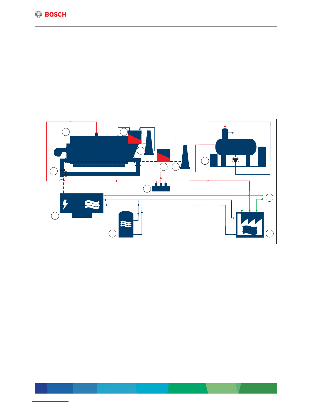
Fig. 1 Simplified function diagram 4-draught steam boiler and CHP module and CHP (simplified depiction)
[1] 4-draught steam boiler
[2] Economiser
[3] Chimney
[4] Flue gas heat exchanger
[5] Water service module
[6] Mains power supply
[7] Consumer
[8] Manifold
[9] Memory
[10] CHP
[11] Flue with bypass
Current
Water/condensate
Steam
Flue gas
If a replacement power supply is necessary, e.g. as in
hospitals or other safety-relevant facilities, a CHP
module can also be used as standby power generator.
6 720 819 535-01.1T
1 2
3
34
5
6
7
8
9
10
11
System components
Systemlösung – 6 720 885 509 (2018/03)
6
2.2 Bosch CHP for external waste heat use
2.2.1 Description CHP CE ... NE
The modular construction system of CHP modules for
external waste heat use in the output range
240 kW
el
... 2000 kWel ensures an operation that
simplifies maintenance, commissioning and planning.
Bosch CHP modules care supplied for external waste
heat use in 2 different types and sizes:
• CHP CE ... NE with an output range to 400 kWel.
based on the approved Bosch CHP modules CHP CE
• CHP CE ... NE in the output range 600 ... 2000 kW
el
is a modular CHP module in the output range of
600 ... 2000 kW
el
.
The CHP module consists of a system module, that
can be extended in function via corresponding
accessory modules.
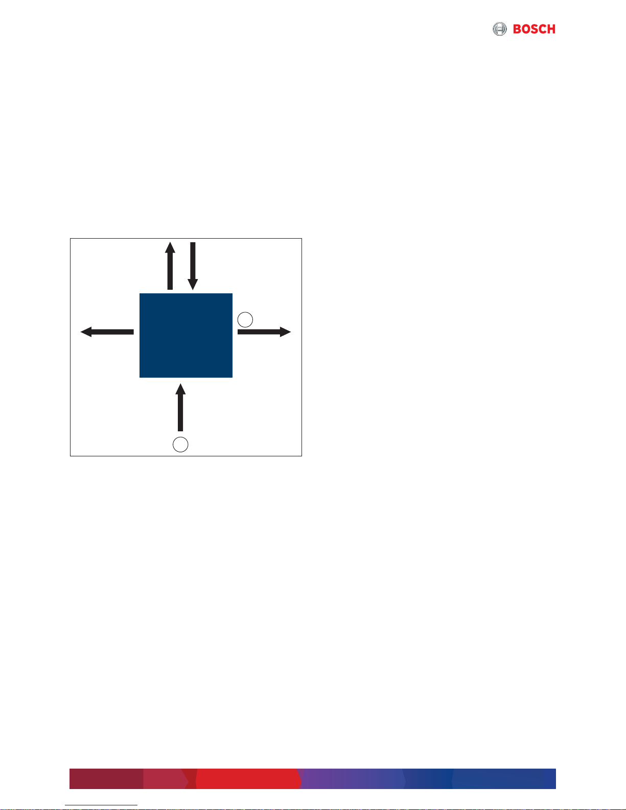
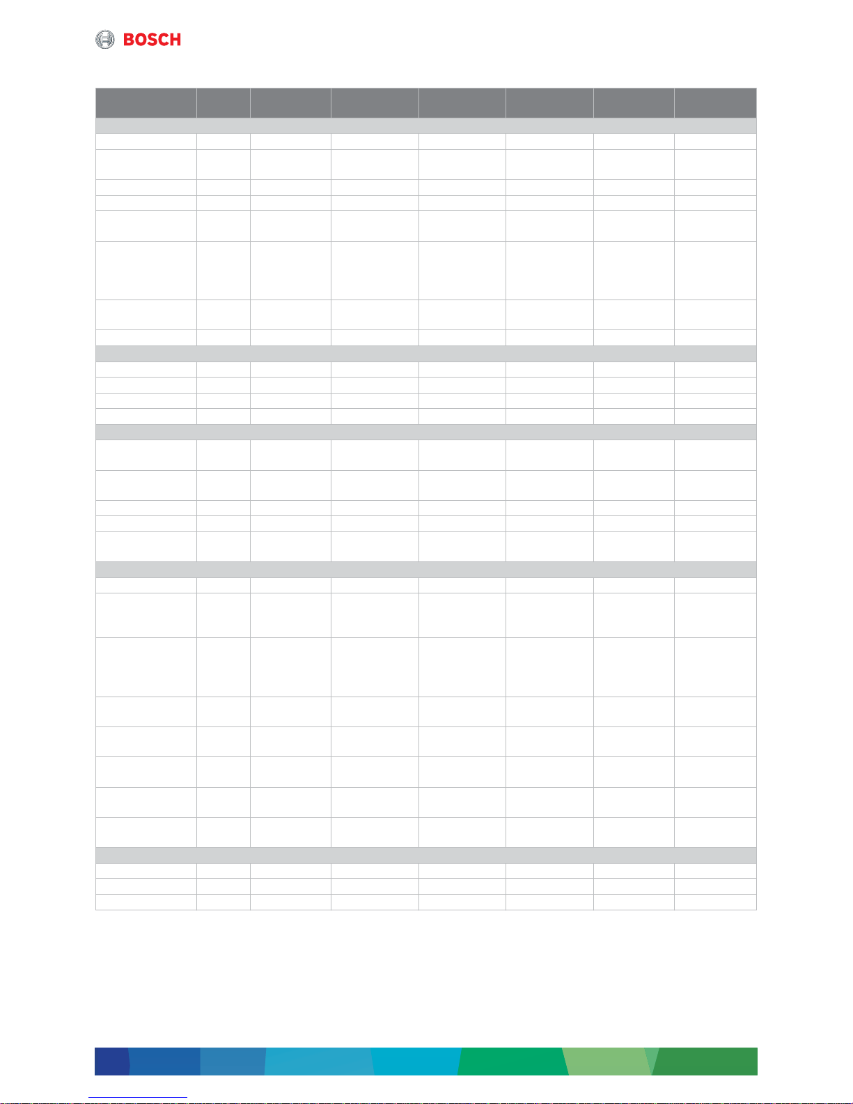
Fig. 2 Decoupling of heat of flue gas and cooling water
in a CHP module, example CHP module with
600 kW
el
performance
[1] Natural gas
[2] Waste heat performance (depending on
temperature change in steam boiler)
Electrical output 240 kW
el
and 400 kW
el
Both CHP modules with electrical output of 240 kWel
and 400 kW
el
are delivered as compact modules, ready
for connection. The components are integrated in the
soundproof cabinet. As ready-for-connection units, the
compact modules are equipped with an integrated
control cabinet. They further comprise a spark-ignited
gas engine (only for CHP CE 400 NE with flue gas
turbocharger) and a synchronous generator for
producing three-phase current (400 V, 50 Hz) and
heating energy. They are suitable for connection,
electrically and for control purposes, to the German lowvoltage network in accordance with VDE-AR-N 4105 or
the regulations of the Federal Association of the German
Energy and Water Industry (Bundesverband der
deutschen Energie- und Wasserwirtschaft, BDEW).
The variant described here spares the internal flue gas
heat exchanger, in consequence the flue gas heat is
available at a high temperature level for external use.
The catalytic converter is installed outside the closed
module frame for easy accessibility.
The flue gas silencers are designed for high
temperatures and a mounted downstream the catalytic
converter and upstream the external heat sink.
Electrical output 600 kW
el
... 2000 kW
el
Modular designed CHP modules are available in the
following output ranges:
• 600 kW
el
• 800 kW
el
• 854 kW
el
• 1200 kW
el
• 1287 kW
el
• 1560 kW
el
• 1718 kW
el
• 1999 kW
el
• 2000 kW
el
The core of the CHP consists of a perfectly tuned unit
with components such as a spark-ignited gas engine
with flue gas turbocharger and a synchronous generator
for producing three-phase current (400 V or 10.5 kV,
50 Hz).
The individual components, such as pumps, heat
exchangers or sensors are combined in modules, wired
and integrated electrotechnically in a terminal box. The
spatial arrangement of the modules can be adapted to
the existing spatial conditions. The options are
constructed in a way that they can be integrated in
existing modules without too much technical effort.
Independently of the ordered options, Bosch CHP
systems provide as standard a comprehensive safety
and fire prevention concept.
The 4-draught CHP modules fulfil, electrically and for
control purposes, the German grid connection
conditions in accordance with
VDE-AR-N 4105 low-voltage or the medium-voltage
regulation by the Federal Association of the German
Energy and Water Industry (Bundesverband der
deutschen Energie- und Wasserwirtschaft, BDEW).
In the variant described here, the CHP module is
designed for external heat utilisation and therefore
provides the flue gas heat for another system. The flue
system is designed for flue gas temperatures up to
550 °C.
Achievable performance of waste heat utilisation in
the steam boiler
The output of the utilised waste heat depends on the
cooling degree of the flue gases in the flue gas boiler. As
an estimate, this is at approx. 20 ... 25 % of natural gas
use in kW.
Bosch BHKW
CHP 600 NE
6 720 819 535-02.1T
1
2 453 °C
75 °C85 °C
333 kW
th
360 kW
th
600 kW
el
1438 kW
~
~
System components
7
Systemlösung – 6 720 885 509 (2018/03)
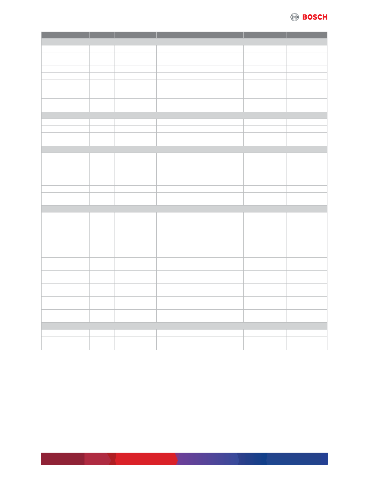
2.2.2 Technical data
Unit CHP CE 240 NECHP CE 400NECHP CE 600 NECHP CE 800
NE
CHP CE 854 NECHP CE 1200
NE
GenSet
Gas category – Natural gas Natural gas Natural gas Natural gas Natural gas Natural gas
Power
consumption
kW 668 1034 1438 1898 1993 2750
Electrical output kW 240 400 600 800 854 1200
Thermal output kW 236 288 333 431 443 625
Electrical
efficiency
% 35.9 38.7 41.7 42.1 42.8 43.6
Type – Design
external flue
gas heat
utilisation
Design
external flue gas
heat utilisation
Design
external flue gas
heat utilisation
Design
external flue gas
heat utilisation
Design
external flue
gas heat
utilisation
Design
external flue
gas heat
utilisation
Engine
manufacturer
– MAN MAN MWM MWM MTU MWM
Engine model – E2842 E 312 E2842 LE 322 TCG 2016 V12 C TCG 2016 V16 C 8V4000 L33 TCG 2020 V12
Dimensions
Length mm 4380 5300 3900 4057 4200 3900
Width mm 1510 1660 2400 1467 2000 2400
Height mm 1980 2472 2260 2190 2300 2260
Weight (empty) kg 4400 6950 6670 7550 10000 11730
Generation of electricity
Generator
manufacturer
– Leroy Somer Leroy Somer Marelli Marelli Stamford Marelli
Generator type – LSA 47.2
M7/4P
LSA 47.2 M7/4P
LSA 49.1 S4/4P
MJB 400 LC4 MJB 450 MB4 PE734C MJB 500 MB4
Voltage/Frequency V/Hz 400/50 400/50 400/50 400/50 400/50 400/50
Speed 1/min 1500 1500 1500 1500 1500 1500
Efficiency of
generator
% 96.1 96.2 96.8 97.1 95.9 97.3
Temperature levels
LT mixture circuit °C – 47.5/45 44/40 46/40 42/40 43/40
Heating water
without flue gas
heat exchanger
°C 83/70 82/72 85/75 85/75 85/75 85/75
Flue gas
temperature
without flue gas
heat exchanger
°C 570 440 453 452 443 414
Maximum flue gas
temperature
°C 650 650 550 550 550 550
Flue gas tube
dimension (KAT)
– DN 200/PN 10 DN 200/PN 10 DN 250/PN 10 DN 300/PN 10 DN 300/PN 10 DN 350/PN 10
Flue gas mass flow
rate (wet)
kg/h 877 2102 3343 4418 4524 6551
Available flue gas
back pressure
mbar 15 17 25 25 25 25
Flue gas back
pressure boiler
mbar 10 10 15 15 15 15
Flue gas limit values
CO mg/m
3
i.N.
d300 d300 d300 d300 d300 d300
NOx mg/m
3
i.N.
d250 d500 d250 d250 d250 d250
NMHC mg/m
3
i.N.
d150 d150 d150 d150 d150 d150
Table 1 Specifications CHP CE 240 NE ... CHP CE 1200 NE
System components
Systemlösung – 6 720 885 509 (2018/03)
8
2.2.3 Operation conditions CHP
The following operating conditions are required to
maintain the warranty:
• Ensure dust and halogen-free cooling and
combustion air
• Ensure that the exhaust air and exhaust gas lines are
correctly dimensioned, and run them separately
• Maximum setup height without a drop in
performance: depending on model used 100 ... 500
meters above zero
• Ratio of starting/operating hours: 1 start to 6
operating hours averaged over the year
• Methane count: 80
• Natural gas Hi = 10 kWh/m
3
• Maximum exhaust gas counterpressure depending on
GenSet motor manufacturer 40 ... 60 mbar
• Module only suitable for setup within a building
• The condensate and flue gas line are pressurized and
must be appropriately designed, and the operating
pressure must be demonstrated in a pressure test.
Unit CHP CE 1287 NE CHP CE 1560 NE CHP CE 1718 NE CHP CE 1999 NE CHP CE 2000 NE
GenSet
Gas category – Natural gas Natural gas Natural gas Natural gas Natural gas
Power consumption kW 2974 3629 3991 4666 4588
Electrical output kW 1287 1560 1718 1999 2000
Thermal output kW 664 819 974 1076 1053
Electrical efficiency % 43.3 43 43 42.8 43.6
Type – Design
external flue gas
heat utilisation
Design
external flue gas
heat utilisation
Design
external flue gas
heat utilisation
Design
external flue gas
heat utilisation
Design
external flue gas
heat utilisation
Engine manufacturer – MTU MWM MTU MTU MWM
Engine model – 12V4000 L33 TCG 2020 V16 16V4000 L33 20V4000 L33 TCG 2020 V20
Dimensions
Length mm 4800 6300 5500 5900 7820
Width mm 2000 1800 2000 2000 1800
Height mm 2300 2500 2300 2400 2680
Weight (empty) kg 12000 13400 15000 19000 18100
Generation of electricity
Generator
manufacturer
– Stamford Marelli Leroy-Somer Stamford Marelli
Generator type – PE734F MJB 500 LA4 LSA 51.2
VL95 C6S/4P
LV804T MJB 560 LB4
Voltage/Frequency V/Hz 400/50 400/50 400/50 400/50 400/50
Speed 1/min 1500 1500 1500 1500 1500
Efficiency
generator
% 96.5 97.1 96.5 96.3 97.4
Temperature levels
LT mixture circuit °C 43/40 44/40 43/40 43/40 45/38
Heating water
without flue gas heat
exchanger
°C 85/75 85/75 85/75 85/75 85/75
Flue gas temperature
without flue gas heat
exchanger
°C 440 426 426 449 410
Maximum flue gas
temperature
°C 550 550 550 550 550
Flue gas tube
dimension (KAT)
– DN 350/PN 10 DN 400/PN 10 DN 400/PN 10 DN 450/PN 10 DN 450/PN 10
Flue gas mass flow
rate (wet)
kg/h 6700 8665 8940 10458 10983
Available flue gas
back pressure
mbar 25 25 25 25 25
Flue gas back
pressure boiler
mbar 15 15 15 15 15
Flue gas limit values
CO mg/m
3
i.N.
d300 d300 d300 d300 d300
NOx mg/m
3
i.N.
d250 d250 d250 d250 d250
NMHC mg/m
3
i.N.
d150 d150 d150 d150 d150
Table 2 Specifications CHP CE 1287 NE ... CHP CE 2000 NE
System components
9
Systemlösung – 6 720 885 509 (2018/03)
2.3 4-draught boiler system
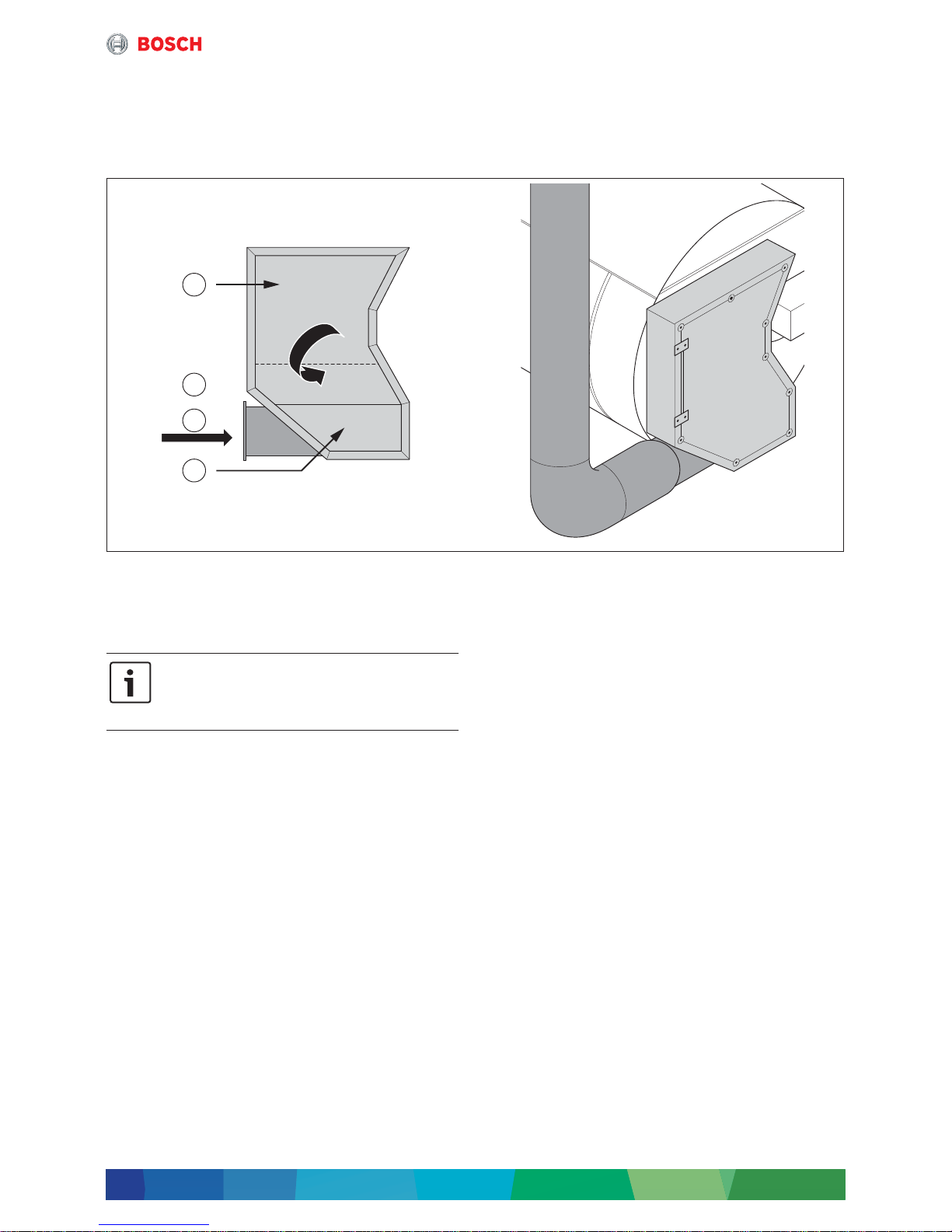
2.3.1 Description of 4-draught boiler system
The basis of a 4-draught steam boiler is a 3-draught
boiler from which a part of the smoke tubes is
separated. The hot flue gases of the CHP module
(in the design for external flue gas utilisation) are lead
through this separate smoke tube field, the so-called
fourth draught, and are used for steam generation.
Fig. 3 Positioning of fourth draught in reversing chamber
[1] Second draught
[2] Third draught
[3] Flue gas
[4] Fourth draught
Due to different pressure ratios on burner and waste
heat side, and for avoiding back coupling, both flue gas
paths have to be clearly separated on the flue gas side.
This separation concerns, besides the boiler and
possibly existing economisers, also the flue gas routing
via 2 separate chimneys.
The auxiliary units required for a 4-draught steam boiler,
such as e.g. water treatment, feed water degassing
system, fuel supply, pumps etc. will not be treated
further in this document, because their requirements
concerning sizing and installation do not differ from a
conventional boiler system.
Especially, it has to be observed that the installation
location of the feed water control valve is between the
two economisers, in order to increase economic viability
and to save steam for heating up the feed water. In
addition, it is recommended to equip the feed water
container with an overflow device.
This ensures that an unwanted activation of the pressure
relief valve at the feed water container is prevented
during waste heat recovery of the CHP module in the flue
gas heat exchanger (ECO2) with at the same time very
low to no steam generation. Both points are shown in
the hydraulics (Æ chapter 3.4, page 34).
6 720 819 535-03.1T
1
2
3
4
By dividing the third draught, the amount of
steam generated by waste heat is limited for
the total output of the boiler
(Æ chapter 3.3.3, page 24).
System components
Systemlösung – 6 720 885 509 (2018/03)
10
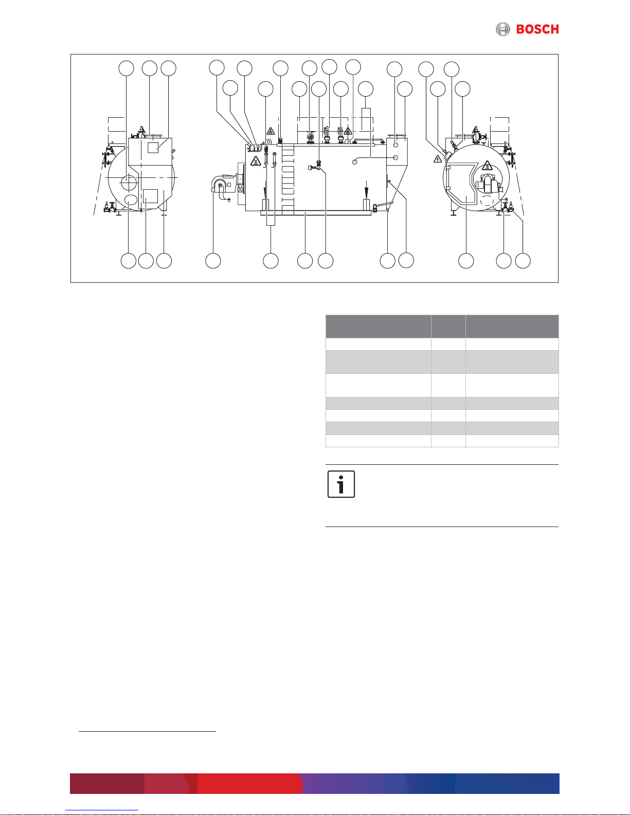
Fig. 4 Overview UNIVERSAL steam boiler
[1] Inspection aperture on the flue gas side
[2] Flue gas connecting branch
[3] Inspection aperture on the flue gas side
[4] Pressure indicator (with test function)
[5] Pressure transducer
[6] Pressure limiter
[7] Shut-off valve
[8] Vent shut-off valve (optional)
[9] Maintenance platform (optional)
[10] Steam shut-off valve
[11] Desalination shut-off valve
1)
[12] Positive pressure safety valve 2 (optional)
[13] Positive pressure safety valve 1
[14] Lifting lug
[15] Connection pipework
[16] Connection economiser
[17] Flue gas heat exchanger
[18] Conductivity transducer
[19] Terminal box
[20] Level measurement transformer
[21] Level limiter
[22] Mud quick action stop valve
[23] Outlet shut-off valve
[24] Reversing chamber door
[25] Flame inspection hole
[26] Connection for flue gas condensate
drainage system
[27] Desalination control valve
[28] Base frame
[29] Level indicator 1
Level indicator 2 (optional)
[30] Burner
[31] Flue gas chamber
[32] Inspection aperture on the flue gas side
[33] Inspection aperture water-side
2.3.2 Technical data
6 720 819 535-04.1T
1 2 3 8710
912111413 17
222324
25
26272830313233 29
19
16 182120
15
6
5
4
1) For boiler type UL-S 28000 there are 2 desalination
connections.
Unit UNIVERSAL
steam boiler
Type – UL-S
Heat transfer medium – High pressure
saturated steam
Type – 4-draught flue tube
technology
Performance kg/h 1250 ... 28000
Safety pressure bar d30
Maximum temperature °C 235
Fuel – Oil, gas
Table 3 Specifications UNIVERSAL steam boiler
The 4 ... 5-digit number in the boiler name
corresponds to the respective steam output
in kg/h.
1 kg/h corresponds to 0.65 kW burner
output.
System components
11
Systemlösung – 6 720 885 509 (2018/03)
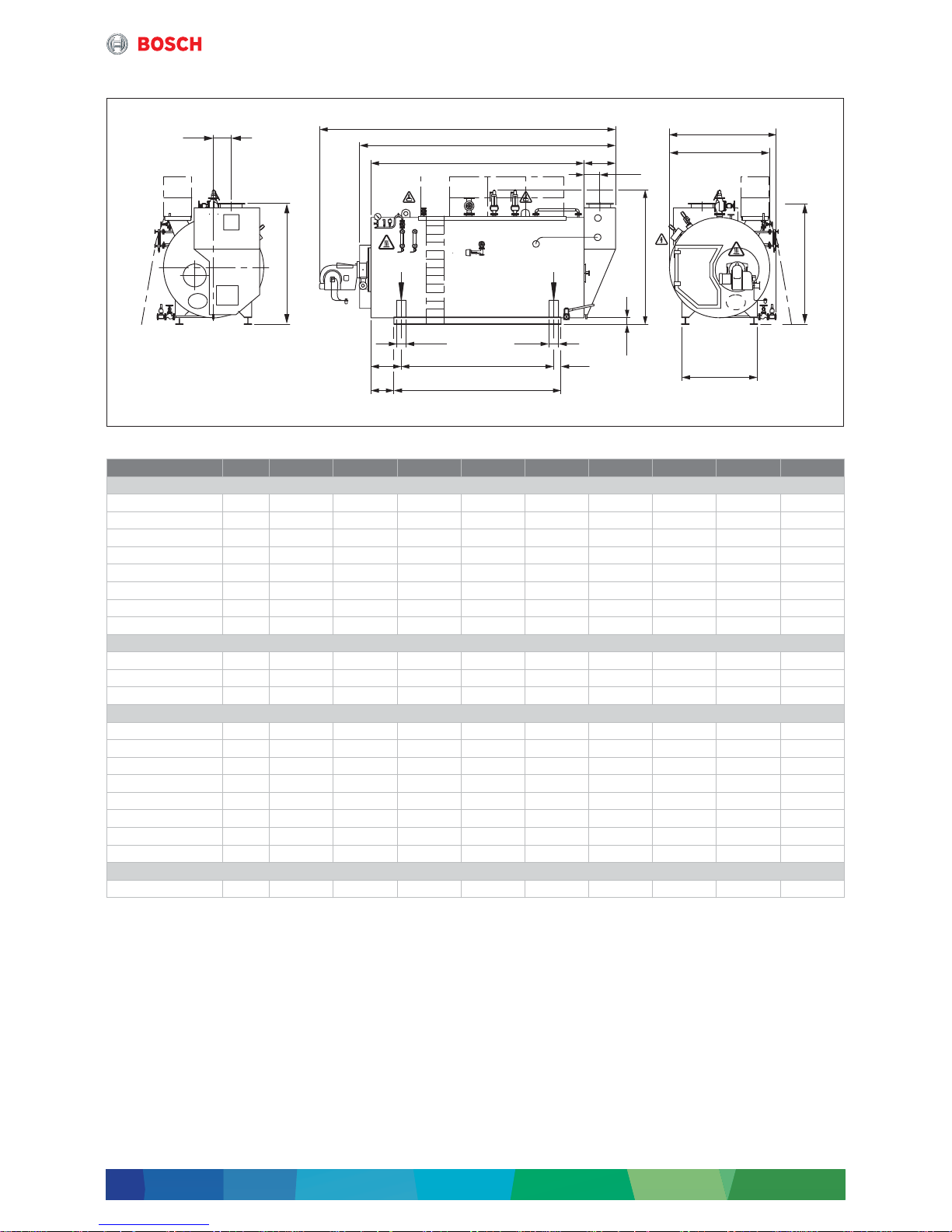
2.3.3 Dimensions and connections
Fig. 5 Dimensions and connections UNIVERSAL steam boiler UL-S
Unit UL-S 1250 UL-S 2000 UL-S 2600 UL-S 3200 UL-S 4000 UL-S 5000 UL-S 6000 UL-S 7000 UL-S 8000
Dimensions
L1
1)
1) The dimension L1 is a recommended dimension and is subject to the burner manufacturer, type and the actual steam output.
mm 4850 4653 4972 5927 6615 6615 7255 7255 7845
L2
2)3)
2) Minimum transport dimensions when valves, burner and terminal box have been removed
(without cable conduit; with cable conduit + 75 mm on the right).
3) Dimension increases depending on dimension of flue of CHP.
mm 3280 3820 4260 4760 5450 5450 6210 6210 6800
L3 mm 2620 2970 3270 3770 4600 4600 5100 5100 5550
L6 mm 500 640 780 780 640 640 780 780 920
B1 mm 1929 2102 2187 2182 2439 2634 2674 2774 2874
B2
2)
mm 1652 1825 1910 1905 2165 2360 2400 2500 2600
H1
4)
4) The dimension H1 varies depending on the valve manufacturer.
mm 2262 2512 2557 2642 2947 3177 3222 3312 3562
H2
2)5)6)
5) Dimension depending on selected flue gas temperature (influenced by number of tubes in height of economiser).
6) For boiler type UL-S 28000 there are 2 desalination connections.
mm 2150 2232 2210 2210 2575 2765 2975 2958 3178
Flue gas connection
L11 mm 233 303 373 373 303 303 373 373 443
B4 mm 170 270 290 290 318 273 119 153 85
H3
5)
mm 2150 2232 2210 2210 2575 2765 2975 2958 3178
Base frame
L4 mm 2270 2570 2120 2625 3750 3500 4000 4000 4450
L5 mm 1890 2150 1770 2175 3400 3150 3650 3650 3950
L7 mm 385 425 750 798 600 775 675 675 800
L8 mm 175 215 575 573 425 600 500 500 550
L9 mm 170 210 175 225 175 175 175 175 250
L10 mm 80 80 150 150 225 225 225 225 275
B3 mm 1060 1100 1360 1360 1655 1785 1820 1890 1950
H4 mm 200 190 135 135 190 165 160 150 170
Wide-flange beam
IPB/HEB – DIN1025 mm – – – – 180 180 180 180 200
Table 4 Dimensions and connections UNIVERSAL steam boiler UL-S 1250 ... UL-S 8000
6 720 819 535-05.1T
L1
L2
L3
L10 L10
L7 L5 L9
L8
L4
L6
L11
B4
H3
H2
H1
H4
B3
B1
B2
System components
Systemlösung – 6 720 885 509 (2018/03)
12
• For information and instructions regarding the
requirements for the boiler installation room
Æ Technical information TI024
(Æ chapter 4.2, page 41)
• Equipment and complete dimensions according to
project-specific technical datasheet
• Measure the maximum weight at the front and back
feet of the foundation.
• Dimensions given with r1 % tolerance
• These dimensions are designed for standard
insulation
– 150 mm thick on floors
– 100 mm thick on casing
• The boiler types UL-S 1250/2000/2600/3200 have
inspection apertures on the right side, instead of the
bottom.
• For boiler types UL-S 1250 ... UL-S 3200, the outlet
shut-off valve and the mud quick action stop valve are
mounted in the boiler axis to the back to ensure
accessibility of the inspection aperture on the
water side.
• The boiler type UL-S 4000 has additional inspection
apertures on the side at the bottom.
• Sizing for the entrance
– Transport height: additional clearance of at least
100 mm from dimension H1 or dimension H2
(valves fitted/not fitted)
– Minimum door clearance: additional clearance of at
least 200 mm from dimension B1 or dimension B2
(valves fitted/not fitted)
• The height of the boiler room is determined by the
system equipment. The clearance above the
maintenance platform should be at least 2 m.
• For boiler types UL-S 1250 ... UL-S 3200 optionally a
shaft extension is available for the steam shut-off
valve.
• Level measurement transformer and level limiter
(image 4, [20] and [21], page 10) are positioned for
boiler type UL-S 1250 and UL-S 2000 on the top of the
boiler.
Unit UL-S
10000
UL-S
12000
UL-S
13000
UL-S
14000
UL-S
16000
UL-S
17000
UL-S
18000
UL-S
22000
UL-S
28000
Dimensions
L1
1)
1) The dimension L1 is a recommended dimension and is subject to the burner manufacturer, type and the actual steam output.
mm 8369 9007 9008 8674 9854 9920 9944 9610 9868
L2
2)3)
2) Minimum transport dimensions when valves, burner and terminal box have been removed
(without cable conduit; with cable conduit + 75 mm on the right).
3) Dimension increases depending on dimension of flue of CHP.
mm 6860 7265 7446 7456 8286 8286 8286 8705 8955
L3 mm 5550 5800 5800 5800 6630 6630 6630 7050 7050
L6 mm 980 1135 1136 1146 1146 1146 1146 1145 1395
B1 mm 3074 3224 3474 3474 3474 3669 3674 3874 4199
B2
2)
mm 2800 2950 3200 3200 3200 3400 3400 3600 4000
H1
4)
4) The dimension H1 varies depending on the valve manufacturer.
mm 3732 3867 4222 4222 4222 4467 4467 4747 5212
H2
2)5)6)
5) Dimension depending on selected flue gas temperature (influenced by number of tubes in height of economiser).
6) For boiler type UL-S 28000 there are 2 desalination connections.
mm 3065 3200 3465 3465 3465 3710 3685 3835 4302
Flue gas connection
L11 mm 503 588 588 598 598 598 598 598 778
B4 mm 240 240 380 380 380 380 380 635 600
H3
5)
mm 2923 2990 3270 3270 3270 3415 3415 3420 3585
Base frame
L4 mm 4450 4450 4700 4700 5500 5500 5500 5800 5800
L5 mm 3950 3950 4200 4200 5000 5000 5000 5200 5200
L7 mm 800 800 775 800 800 800 800 925 925
L8 mm 550 550 525 550 550 550 550 625 625
L9 mm 250 250 250 250 250 250 250 300 300
L10 mm 275 275 275 275 275 325 325 325 325
B3 mm 2080 2180 2340 2340 2340 2365 2365 2500 2700
H4 mm 140 125 140 140 140 185 185 160 225
Wide-flange beam
IPB/HEB – DIN1025 mm 200 200 240 240 240 260 260 260 300
Table 5 Dimensions and connections UNIVERSAL steam boiler UL-S 10000 ... UL-S 28000

System components
13
Systemlösung – 6 720 885 509 (2018/03)
2.4 MEC System – overview
Transparent, efficient, smart
The MEC System (Master Energy Control) is a platform
for planning individual and customer-specific energy
supply systems. With the MEC system, you can combine
and control different plant types and field devices to
achieve an efficient energy system via user interface. The
MEC system is used in commercial, industrial and
communal sectors and is sold as system solution with
Bosch heat sources.
Activation
The MEC system controls different plant types
(e. g. boilers, CHPs) and the required system field
devices (e. g. pumps, valves). For this purpose, it
provides a large range of interfaces and, besides
integration of Bosch devices, it allows for integration
of existing and third-party products.
System control
The system control is the core know-how of the MEC
systems. As manufacturer of energy generation plants,
Bosch used its entire expert knowledge for developing
control and allows in consequence for optimum system
control with adherence to the system's operating
conditions.
Control for energy generation
The MEC system integrates for energy generation as
standard the following plant types:
• Warm water boiler
• Hot water boiler
• Steam boiler
• Biomass boiler
• CHP modules
• Solar
• Heat pumps
• Buffer storage tanks
• External heat
Further systems and plants are available on request.
Control for heat distribution
The range of functions for control of heat distribution
comprises:
• Local heat network
• Heating circuits
• Fans
• Heating circuits
• DHW heating
Further functions and control of systems and devices are
available on request.
System access
The MEC system gives humans and machines access to
the entire system:
• Via an integrated local web server, the user can
access the system using any terminal device
(such as PC, notebook or tablet) in the network with
a standard web browser.
• With the modern and intuitive user interface, the user
can access the complete system and each individual
plant.
• Having a large number of interfaces, the MEC system
allows for integration in super-ordinate systems, such
as building control systems, process control systems,
energy management and virtual power plant systems.
• Using MEC remote, the user has the opportunity to
access the local system from the Internet via a safe
connection.
Web and IP technologies
Web and IP technology have the following benefits:
• HMI scalable to different screen sizes
• Mouse and touch screen operation
• Unlimited number of terminal devices for visualisation
• Location-independent for terminal devices and
controller
• Simple network building with standard components
for large factory sites
• Easy integration in corporate networks
Comprehensive HMI functionality
The modern and intuitive HMI of the MEC system has
many benefits:
• Coloured, clear visualisation of states, temperatures
and performance
• Visualisation of device, system and operation
• User management
• Alarm management with alarm history
• Appliance configuration via HMI system
• Search
• Dashboard function
• Energy monitoring
• Diagram displays
• Export and print-out of graphs
• Transmission of alarms via e-mail, text message, fax
• Run time prognosis of CHP module
New HMI standards
The MEC system uses new standards for visualisation:
• The concept of operation is tuned to the end
customer's requirements
• Intuitive and new operation
• Structured and clear design
• Modern design
System components
Systemlösung – 6 720 885 509 (2018/03)
14
2.5 Further options for waste heat use/peak load boiler
As an option, for waste heat use only of a CHP, further
Bosch industrial boilers can be used.
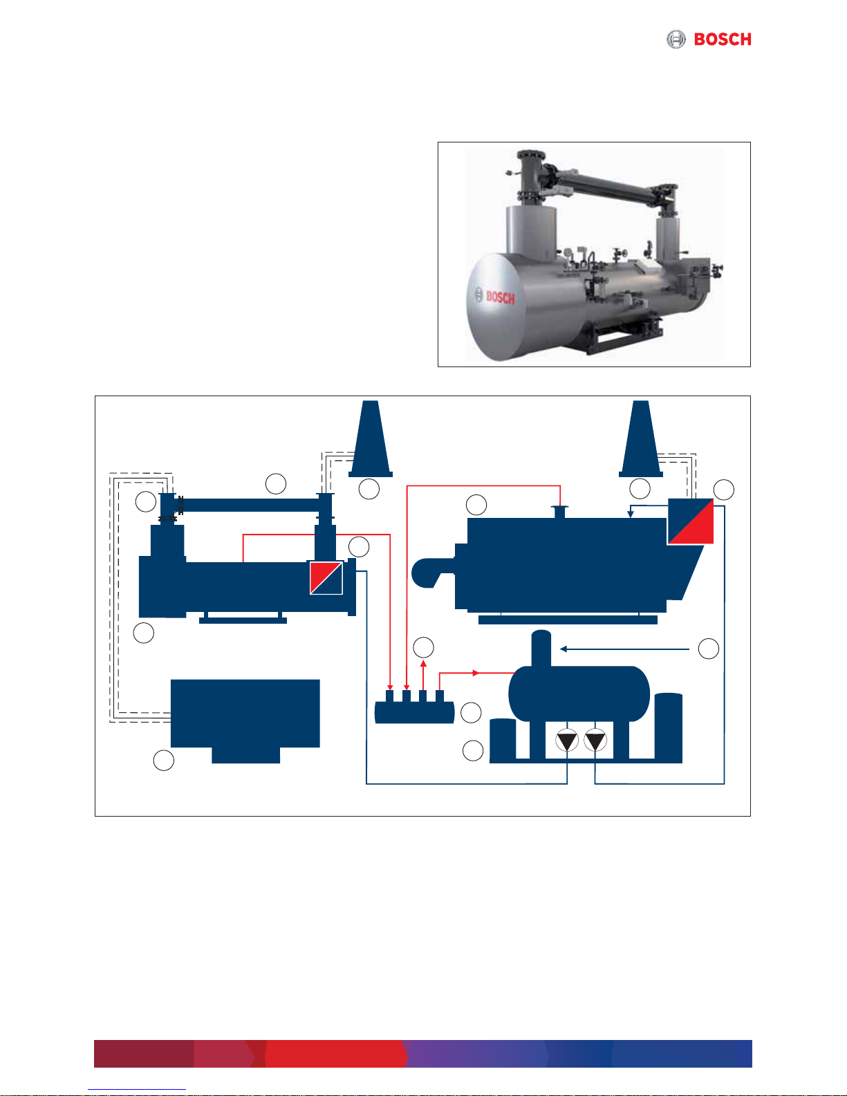
2.5.1 Waste heat boiler HRSB
As alternative to a 4-draught industrial steam boiler, a
pure waste heat boiler can be used. This variant should
be preferred in case of retrofitting (existing boiler
system). A bypass already exists in the waste heat boiler.
Fig. 6 Bosch waste heat boiler HRSB
Fig. 7 Simplified function diagram Bosch waste heat boiler HRSB and CHP (simplified depiction)
[1] Flue CHP module
[2] Flue bypass
[3] Chimney
[4] Economiser
[5] Peak load steam boiler
[6] Make-up water
[7] Water service module WSM-V
[8] Manifold
[9] Consumer
[10] CHP
[11] Waste heat boiler
Water/condensate
Steam
Flue gas
6 720 819 535-11.1T
6 720 819 535-12.1T
1
2
3
3
4
4
6
7
8
9
10
11
5
 Loading...