

Bosch BSS250E-2, BSS250-21-2, BSS250-26-2, BSS300E-2, BSS300-21-2 Installation And User Manual
...
19/07/2011 Version 19 Solar Wizard
MODELS
BSS250E-2 / BSS250-21-2 / BSS250-26-2
BSS300E-2 / BSS300-21-2 / BSS300-26-2
BSS400E-2 / BSS400-21-2 / BSS400-26-2
Australia & New Zealand
INSTALLATION AND USER
HANDBOOK
System Installation
Controller & Pump
Solar Panels
Gas solar booster
Solar Tank
This solar hot water system must be installed in accordance with the manufacturer’s installation
instructions, AS5601, AS3500.4. AS3000 wiring regulations (in New Zealand NZBC G12) and all Local
Building, Water and Gas fitting regulations.
To be installed and serviced only by an authorised person
This appliance is not suitable for use as a pool heater
Please see important note regarding tank on Page 15
The “authorised installing person” is responsible for:
1. Correct commissioning of this system.
2. Ensure units perform to the specifications stated on the rating label.
3.. Demonstrate operation of the system to the customer before leaving.
4. Hand these instructions to customer.
Failure to install this system in accordance with these installation instructions may void warranty
Note: These instructions are subject to change, due to continuous product improvement.

2
INDEX
Page Number
Basic Solar Hot Water Layout 3 - 4
Introduction 5
Basic Installation steps 5 - 6
Contents 7
Solar Collectors 8- 14
Solar Tank and Components 15-21
Electric Boosting 22-23
Solar Tank Specifications 24
Gas Boosting 25-32
Controller & Pump 32-42
Commissioning 42
Home Owners Guide & Safety Instructions 43-50
Warranty Details 51-52
3
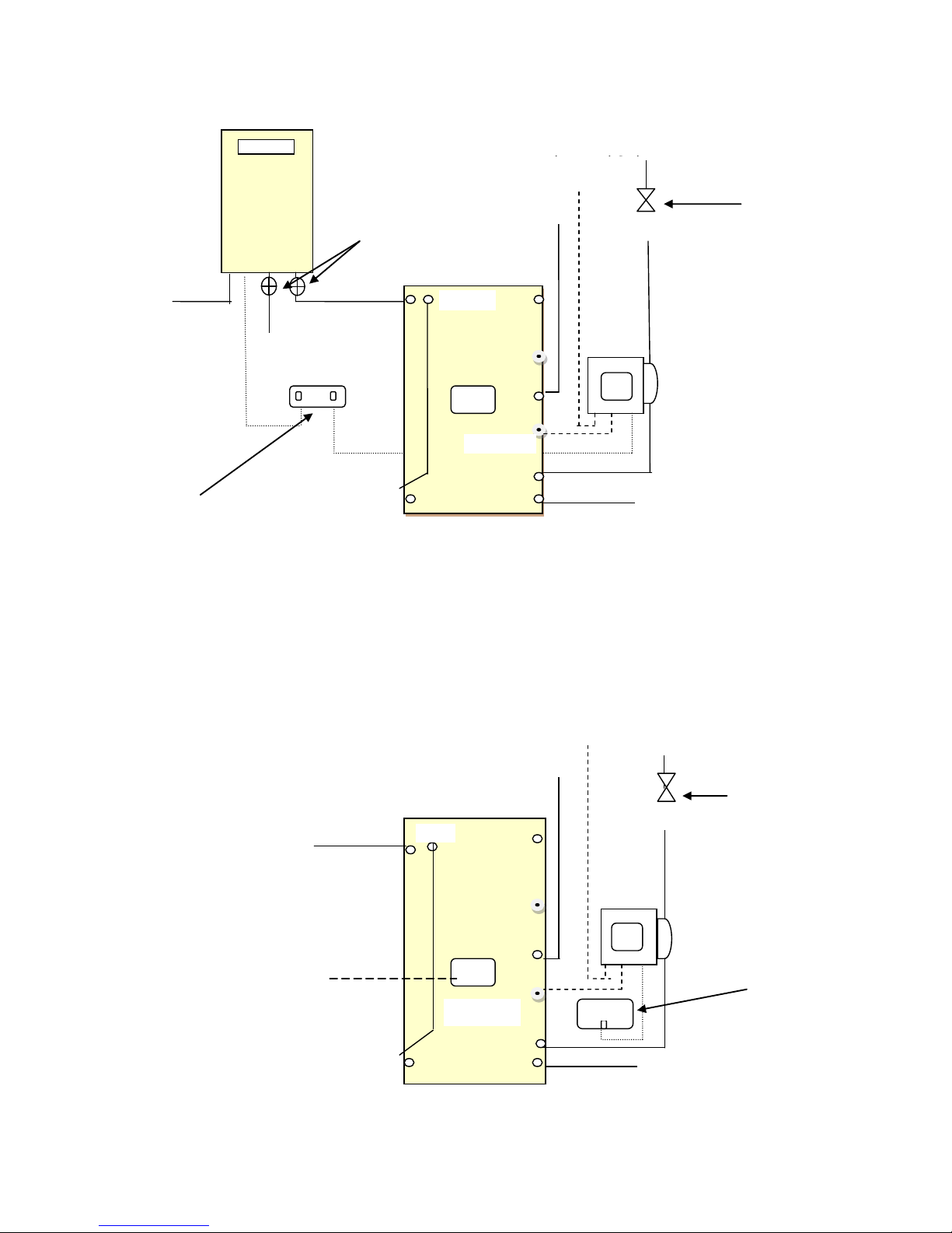
BASIC SOLAR TANK AND COMPONENT LAYOUT
I
250L, 300L & 400L Gas
Solar Booster
Set to 75°c
Hot water supply to fixtures
(Temperature control valve Must be
fitted)
Gas
piping
Dual GPO
Power supply to
solar pump &
controller
Solar storage tank
Cold water inlet valve train isolation valve, non-
return valve PLV (600Kpa & cold water expansion
(Where required)
Solar circulation
pump and controller
Tank outlet
Tank sensor
Solar return
from panel
Solar panel sensor
Flow to panels
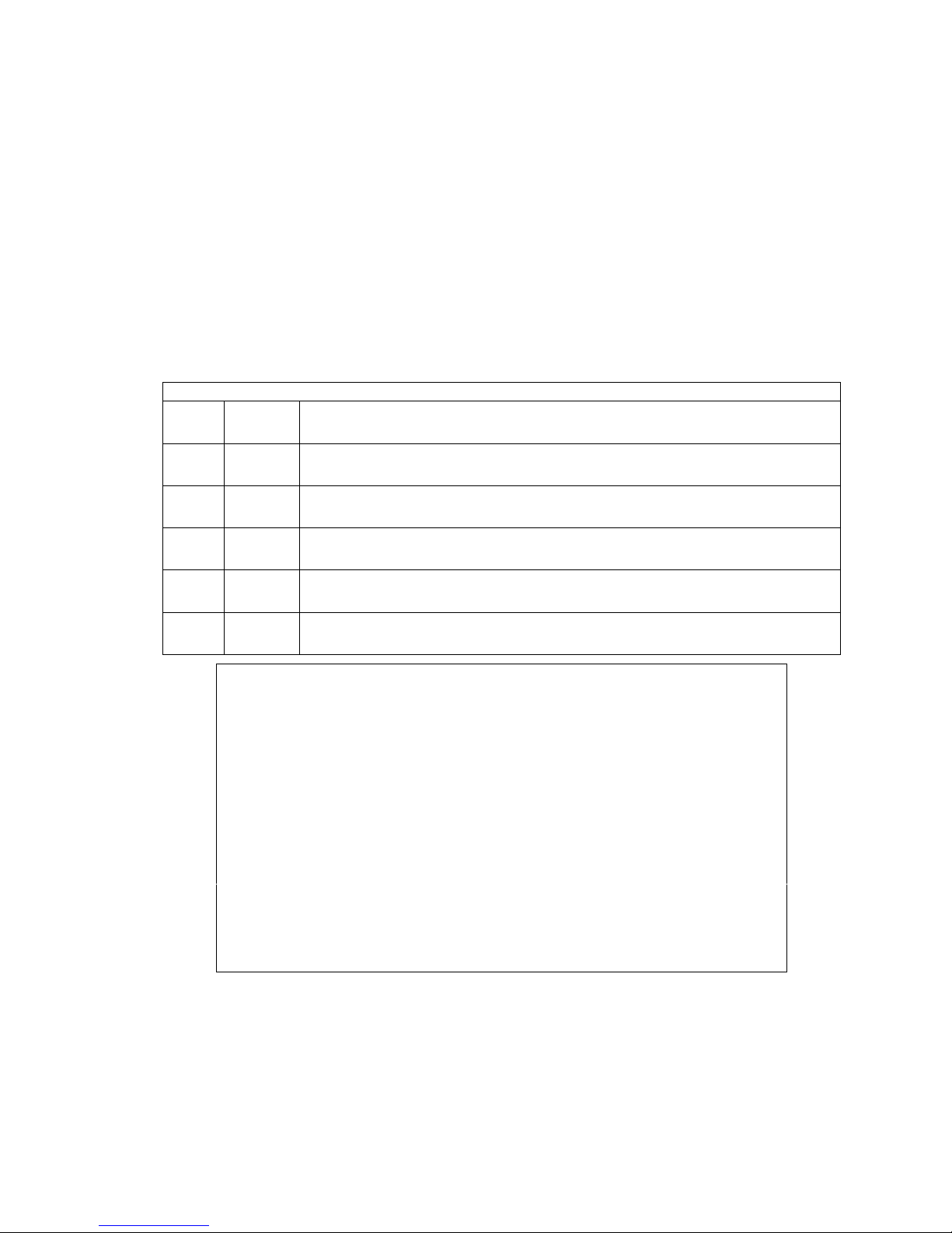
250L, 300L & 400L Electric boosted solar
PTR
*NOTE For ease of installation, the tank has
cold inlet and hot outlet ports on both the left
and right hand sides
Cold water inlet valve train isolation valve, nonreturn valve PLV (600Kpa & cold water
expansion (Where required)
Hot water supply to fixtures
(Temperature control valve
Must be fitted)
Power supply from
switchboard to
booster
GPO
Solar circulation
pump and controller
Flow to panels
Solar panel sensor
Solar return from
panel
PTR
Tank sensor
Solar storage tank
*NOTE For ease of installation, the tank has
cold inlet and hot outlet ports on both the left
and right hand sides
Continuous
supply
Continuous supply
Non-Return valve
Non-Return valve
Isolating
valves

4
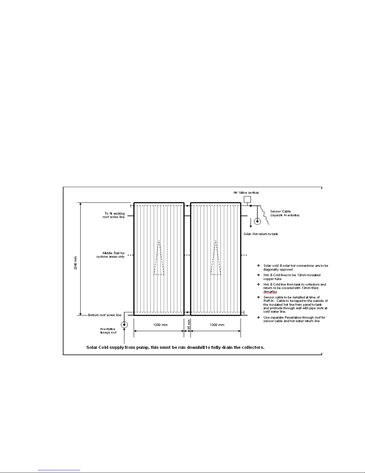
BASIC PANEL LAYOUT 1,2 & 3 PANEL
Solar Panel
2040 x 1200
Auto Air vent
Must be upright and
ensure vent cap is
open
Custom fitting to suit top left of
collector with inbuilt sensor socket
and connection for Air Relief Valve
Frost valve
¾ x ½ nipple
Cold water flow
from pump
¾ Barrel union
with pipe insulation
*NOTE: All pipes and fittings must be
lagged with pipe insulation to prevent
heat loss.
Brass plug
Return to tank
Custom
fitting for
inlet
connection

5
INTRODUCTION
The following instructions are for the installation of a Split solar hot water system/s, being the
panels are mounted on the roof of the dwelling and the solar tank is located either internally or
externally at ground level. Where a gas solar booster is to be used, it should be mounted
adjacent (In an external location) to the solar tank.
BASIC INSTALLATION STEPS
Check packaging and product for damage (If the product is damaged, do not install and
contact your supplier immediately)
Check and ensure that you have all components as listed on page 7
Panel installation (See page 7 – 14 for more detail)
Select Panel location
Facing north (Not unduly shaded during the day and to the pitch requirements)
Roof structure can support filled weight of panels (44Kg each)
Panels can fit on available space on the roof (Panels are 1200mm x 2040 plus pipe
and fittings)
At and before installation, cover panels to prevent excessive heat building up in the
panels that may cause damage to the panels and personal injury.
Fix panels securely with brackets provided (in Cyclonic areas, cyclone kits are
required)
Tank location (See page 15- 22 for more detail)
As close as possible to the most frequently used fixture
As close as possible to the solar panels (Max 8m)
Ensure the tank is mounted on a solid base
Power, water is accessible to be connected to the tank and system
PTR drain is discharged in a safe manner and conforms to AS 3500.4
Note There are inlets and outlets on both sides of the tank, so ensure the unused
points are plugged with brass plugs prior to filling the tank.(Plastic plugs must be
discarded)
Tank is fitted in accordance with the manufacturer‟s installation instructions,
AS3500.4. AS3000 wiring regulations (in New Zealand NZBC G12) and all Local
Building, Water regulations.
The piping between the panels and tank is copper and is well insulated.

6
Pump & Controller (See page 30 - 39 for more detail)
Pump and controller is securely mounted on a wall to the side of the tank (within
500mm of the tank.) The power supply lead to the pump and controller is 1500mm in
length.
A continuous supply power point is within 1.5 metres of the controller.
Run sensor leads to the tank and panels (it is recommend that the sensor leads are
protected from the elements and mechanical damage)
Gas Booster (See page 23 - 29 for more detail)
Booster is mounted on either the left or right hand side of the tank
The 75c bridge is fitted to the booster. (See page 29 for more detail)
A continuous supply power point is within 1 metre of the booster.
Booster is fitted in accordance with the manufacturer‟s installation instructions,
AS3500.4. AS3000 wiring regulations (in New Zealand NZBC G12), AS 5601 & NZS
5261 and all Local Building, Water regulations.
Commissioning the system
Once the installation is complete the system will need to be filled with water and
commissioned.
First flush all piping of debris.
Turn the water isolation valve on at the tank.
Check pipework for leaks.
Open household taps individually and purge out any air.
Open vent on auto vent cap (At panels).
For electric boost turn power supply onto tank.
Turn power supply onto Controller/Pump station
For gas boost turn on isolation valves at booster.
Plug in three pin plug to power supply and turn on
Commission booster (See page 29 for more detail)
Check and adjust temperature control valve
7
Clean up site
Hand the customer the operating instructions
Explain the system operation
Answer any customer queries.
CONTENTS
Your „Solar Wizard‟ Solar hot water system is supplied with the following components:
Parts List
Item
No.
Qty
Description
1
1
storage tank
2
1 or 2
solar collector
3
2
2610mm (L) x 38mm (W) x 25mm (H) x 1.6mm (T) Upper mounting rail
– 3 units required for Cyclone areas or Standard bracket kit
4
1
Solar PK1 – Panel Installation Kit (See contents below)
5
1
Pump station & Controller
*Optional tank installation kit available as an accessory.
Please check to make sure all these components are included with the kit.
Solar-PK1
Panel Installation Kit
20mm Barrel Unions (MI x MI)
2
Custom Connection for top left of collector include
Sensor Pocket
1
Custom Connection for bottom right of collector
1
20mm x 15mm Hex Nipple
15mm Hex Nipple
1
15mm MI x C Unions
1
20mm Brass Plugs
5
NVHT-15F-15C
15mm High Temperature Non-Return Valve
1
AEHT-10
Air Eliminator
1
FPV15
Anti-Frost Valve
2
PTR15/1000
15mm 1000kPa TPR Valve
1
Note
Insulation kits for most valves & Fittings

8
SOLAR COLLECTORS
The solar panels absorber material is Black painted copper fins, the outer casing is
constructed from corrosion resistant brown anodized aluminum and the glass is low-ironed
prismatic glass.
Width (mm)
Length (mm)
Weight empty (Kg)
Weight Full (Kg)
1200
2040
42
44
SOLAR COLLECTOR LOCATION
The solar collectors must be installed in a shade free position.
The solar collectors are to be installed facing toward the equator (i.e. north facing in the
southern hemisphere and south facing in the northern hemisphere). Where this orientation is
not practical, a system facing up to 45° from the equator will have its efficiency reduced by
approximately 4%.
Inclination of the solar collectors should be approximately equal to 90% of the local latitude
angle.
Solar collectors may be installed at the roof angle for simplicity of installation and appearance,
but must never be flat. If the roof angle varies by 15° from the correct angle, efficiency will be
reduced by 10%.
The installer must ensure the structural integrity of the building is not compromised by the
solar water heater installation and the roof structure is suitable to carry the full weight of the
solar collector(s). If in doubt the roof structure should be suitably strengthened.
Each solar collector and its fittings weighs approximately 44 kg when full of water.
INSTALLATION – SOLAR COLLECTORS
PREFACE:
Approximate roof area required:
2 Collectors are 2.8m wide x 2.4m high. (88kgs total, filled with water)
3 Collectors are 4m wide x 2.4m high. (132kgs total, filled with water)
NOTE: Ensure the mounting surface is strong enough to support the collectors. Most roofs can
support the panels, but if unsure consult a structural engineer.
ONLY QUALIFIED TRADESPERSONS SHOULD INSTALL THESE COLLECTORS.
GLAZING CANNOT BE REPLACED ONSITE.
FRAME INSTALLATION Tiled roof (Non Cyclone Area)

9
Conduct an inspection of the intendant installation position and ensure that the
panels can be fitted in this position prior to commencing any work.
1. Position the lower bracket on the roof ensuring there is sufficient room to fit the panels.
2. Remove the row of tiles above the bracket position.
3. Loop bracket support strap through the bracket and fix bracket support to the roof
rafters, Ensure the bracket is level.
4. Flatten out return of bracket strap
5. Bend all bracket straps to fit over tiles.
6. Replace tiles above the bracket
7. Unpack panels (where fitted remove protective plastic from the panels)
8. Place panels into position and fit against lower bracket
9. Join the panels together using the brass barrel unions supplied in the panel installation
kit.
10. Centre the panels onto the lower bracket and secure the panels onto the bracket 20mm
above the bottom of the bracket using the hex screws supplied. Warning: Do not drill
above 20mm from the bottom of the bracket, as this may cause damage to the internal
workings of the panel and this will void the warranty.
11. Remove the row of tiles above the panels to enable the upper bracket to be fitted.
12. Loop bracket support strap through the bracket, Flatten out return of bracket strap
13. Secure bracket to panels 20mm above the bottom of the bracket using hex self-drilling
screws. Warning: Do not drill above 20mm from the bottom of the bracket as this may
cause damage to the internal workings of the panel and this will void the warranty.
14. Fix bracket support strap to the roof rafters.
15. Bend all bracket straps to fit through and over tiles.

10
16. Replace tiles
17. Make all water connections, fit all valves and components as per the solar layout
diagram contained in these instructions.
18. Note: The panels should be covered fully to prevent the panels heating up to
temperatures that have potential to cause damage or injury during system fill or
commissioning.
FRAME INSTALLATION metal roof (Non Cyclone Area)
Conduct an inspection of the intendant installation position and ensure that the
panels can be fitted in this position prior to commencing any work.
1. Position the lower bracket on the roof ensuring there is sufficient room to fit the panels.
2. Level the panel bracket and fix to the steel roof using roofing screws or rivets, one
fastener per rib is recommended.
3. Weather proof screw heads and rivets with silicone sealant.
4. Unpack panels (where fitted remove protective plastic from the panels)
5. Place panels into position and fit against lower bracket
6. Join the panels together using the brass barrel unions supplied in the panel installation
kit.
7. Slide the upper panel support bracket under the top of the panels then press it flush
against the top of the panels. Mark its position on the roof.

11
8. Remove the panels, align the upper bracket with the marked line and fix the panel to
the steel roof using roofing screws or rivets.
9. Weather proof screw heads and rivets with silicone sealant.
10. Refit the panels between the brackets.
11. Centre the panels onto the brackets and secure the panels onto the brackets 20mm
above the bottom of the bracket using the hex screws supplied. Warning: Do not drill
above 20mm from the bottom of the bracket, as this may cause damage to the internal
workings of the panel and this will void the warranty.
12. Make all water connections, fit all valves and components as per the solar layout
diagram contained in these instructions.
13. Note: The panels should be covered fully to prevent the panels heating up to
temperatures that have potential to cause damage or injury during system fill or
commissioning.
FRAME INSTALLATION (Cyclone areas):
1. Select a suitable place to install the lower mounting rail on the
roof, align panel location as high as possible on the roof.
2. Locate lower rail and mark 4 bolt positions on the rail. The
bolts are positioned to line up with the peaks of the tin or tile
profile. DO NOT drill in the troughs of the roofing material.
Ensure the holes are a minimum of 120mm from the end of
the rail.
3. Drill the 4 bolt positons on the top of the rail using a 16-20mm
metal cutting hole saw, leaving a 5mm pilot hole through the
bottom of the rail.
4. Using the drilled rail as a guide mark and drill the roof material
with a 5mm pilot hole. This may not be needed for tin roofs, as
the screws supplied are self tapping.
5. For tile roofs drill the tiles using a 12-14mm concrete drill bit,
paying careful attention for any cracking in the tiles. Replace
any cracked tiles with a new tile before continuing.
6. Once the holes have been drilled fill the hole with silicone
sealant, and apply a 6mm bead around hole.
7. Apply silicone into the drilled hole then insert the Aluminium spacer tube into the
hole. This is not required for a tin roof.
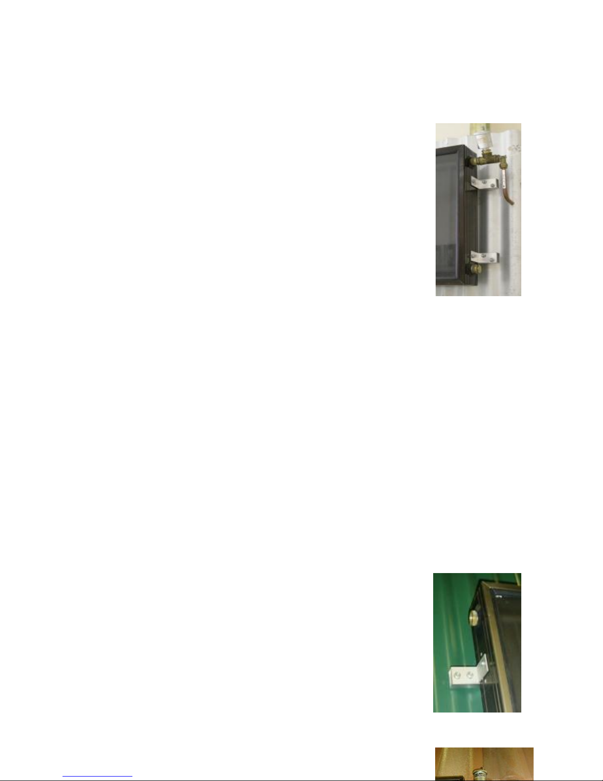
12
8. Position the mounting rail and insert the screws through the rail and into the roof
batten, place a rubber washer as a seal between the roof surface and the mounting
rail, then evenly tighten the screws. Do not over tighten and break a tile.
NOTE: ensure a rubber sealing washer is placed between the
rail and the roof surface for each screw hole, to provide
adequate sealing of the screw hole from water ingress. Use
adequate amounts of silicone sealant into the holes before
placing the screws in the holes.
9. Also ensure that the fixing screws are of sufficent length to
adequately secure the brackets to the roof.
10. Measure and where possible evenly space the three rails to
fit under the panels.
11. Fit the middle and top rails as per steps 3 thrhough to 9.
12. After the three mounting rails have been fixed to the roof, fix a
set of side brackets on the lefthand edge of each of the rails.
Then lift the first panel into place and fix that panel to the rail
bracket. Once this has been done you can then lift the 2nd
panel into place and using the two barrell unions supplied in
the panel fixing kit, join the 2nd panel to the first panel.
13. Then fix the second panel to the rail brackets. The panels are
now secure.
14. A total of 3 rails are required for cyclone rated areas.
15. Connect them as shown in the diagram, remembering to use
Teflon tape or approved liquid sealant on all plumbing joints.
16. Always use two spanners to tighten panel fittings, and do
not exert any torque on the panels.
17. NOTE: WATER FLOW THROUGH PANELS - the water inlet
from the pump must be connected to the lower header pipe of
the array. Ensure that the water exits the panels from the top

13
header pipe, diagonally opposite from the inlet and returns to
the “Solar Return” on the tank.
18. Install the air bleed valve onto the outlet of the panels at the top
Left hand corner of the panels.
19. NOTE: The air bleed valve needs to be commissioned and checked to ensure the
valve top is opened and that when the pump operates the valve seals properly. This
can be done by listening to the valve to ensure air is not entering the pipe work. Let
the pump run for 3-5 minutes if air is still bubbling into the tank at this stage the
valve is not sealing.
20. Mount the panel temperature sensor to the Air bleed T piece
and the tank sensor into the top (Middle of tank) sensor
drywell.
21. Drill a 10mm hole in the roof near the sensor and run the
sensor leads through the hole drilled in the roof, once this is
done seal the hole with silicone.
22. NOTE: Do not use the same hole as the pipe work as movement of
the pipes will case the cable to break or short circuit.
23. Install the Solar Hot Pipe and Solar Cold Pipe to run between the storage tank and
the collectors. Both pipes should be DN15 (1/2”) copper pipe, with 13mm or thicker
synthetic rubber insulation (Armaflex, Bradflex). All insulation should be protected
from UV degradation by two thick coats of paint, or by covering with ductwork. Prelagged pipe (often green PVC or plastic insulation) is not suitable for thermal
insulation purposes – only use foamed synthetic rubber insulation.
24. Connect the Solar Hot Pipe and Solar Cold Pipe to the heater and to the panels.
NOTE: Ensure that the water inlet from the system pump flow is to the lower right edge of
the array, and that the water exits the panels diagonally opposite and through the sensor
outlet fitting, and returns to the solar return on the tank.
14
Upon completion of the water heater installation, check the panels and associated
plumbing for leaks while the pump is operating.
COLLECTOR INSTALLATION IN CYCLONE AREAS
The solar panels are SUITABLE for installation in cyclonic locations when installed with an
additional rail mounting and brackets to provide the required additional fixing to the roof frame.
This ensures conformance with AS1170.2. Three mounting rails meet the requirement for a C3
rated area.
Note: Drawing for illustration purposes only, connection points may vary from product to
product.

15
SOLAR TANK
Important Note: Please ensure you remove plastic transit plugs from tank and replace with
brass plugs supplied with panel fitting kit (These plastic plugs will not withstand solar water
temperature and will melt causing leakage from tank).
Solar tanks are available in 250 Litre, 300 & 400 Litres capacities. All three tanks have cold
water inlet and hot water outlets on both the left and right hand sides of the tanks for
convenience. The connection points not used must be sealed off with the brass plugs
supplied.
The Solar tanks have incorporated a single element electric solar booster, or the system can
be boosted via a gas booster separate to the solar tank.
The inner tank is manufactured from mild steel sheet coated with a special porcelain enamel.
The tank is protected from corrosion by two magnesium anode rods, which softens the water
and lengthens the service life of inner vessel.
The inner vessel is insulated by a thickened high-density, environment friendly polyurethane
thermal insulation layer.
The external casing is a high quality galvanized sheet shell, with outdoor coating technology,
anticorrosive and rust-resistant, makes for a longer service life.
250 Litre
300 Litre
400 Litre
DIMENSIONS (mm)
Height
1325
1545
1600
Diameter
620
620
710
Material & thickness of
inner vessel
BTC340
R-2.0mm
BTC340
R-2.0mm
BTC340
R-2.0mm
Material and thickness
of shell
Galvanised sheet
0.5mm
Galvanised sheet
0.5mm
Galvanised sheet
0.5mm
Insulation thickness
40mm
40mm
40mm
Minimum inlet Water
Pressure
200 kPa
200 kPa
200 kPa
Maximum inlet Water
Pressure
750 kPa
750 kPa
750 kPa
Connection Cold
20mm
20mm
20mm
Connection Hot
20mm
20mm
20mm
Connection solar
15mm
15mm
15mm
ELECTRICAL
(Not applicable for gas boosting)
Power
240v/50Hz
240v/50Hz
240v/50Hz
amps
15
15
15
Elements
3.6kW
3.6kW
3.6kW
Weight
75Kg
95Kg
112Kg

16
INSTALLATION – STORAGE TANK
COMPLIANCE WITH STANDARDS
The installation must be performed by an Authorised Persons and comply with the
requirements of AS/NZS 3500.4, AS/NZS 3000 in New Zealand NZBC G12 and all local codes
and regulatory authority requirements. It is recommended the solar storage tank be installed
at ground or floor level. The water heater must stand vertically upright.
SUITABILITY FOR INSTALLATION IN FROST AREAS
The system is suitable for installation in areas that experience sub-zero temperatures; it has
an air bleed valve freeze protection system integrated into the system to prevent damage in
the event of a light frost. Areas of known heavy frost or altitudes higher than 600 m above sea
level are not suitable for this system. The minimum temperature these systems are suitable for
in no lower than -5°C.
NOTE: THIS WATER HEATER IS NOT SUITABLE FOR POOL HEATING.
LOCATION
Whether located outdoor or indoor, the solar water storage tank should be installed close to
the most frequently used hot water outlet (typically the shower) and its position chosen with
safety and service in mind. The panels should be located as close as possible to the storage
tank.
CLEARANCES
Allow adequate room to work with tools. A minimum of 250mm clearance around the water
heater is required. An additional 300mm is required for relief valve removal, 800mm for access
cover removal and 400mm for element removal. You should be able to read the information on
the rating plate and all informative labelling.
 Loading...