

Bosch AMC2-4W Installation Manual
Access Modular Controller
AMC2-4W
en Installation manual


Table of contents
1
Safety Instructions 5
1.1 Important Safety Notes 5
1.2 Safety Precautions 7
1.3 Unpacking 9
2
Important Information 10
2.1 Explanation of symbols in this document 10
2.2 Internet 11
3
Introduction 12
3.1 Description 12
3.2 Equipment Configuration 14
3.3 Performance Characteristics 16
3.4 System Overview 17
4
Installing 20
4.1 Mounting 20
4.2 Unmounting 21
4.3 Opening the Case 22
4.4 Closing the Case 23
4.5 Cabling 24
4.5.1 Conductor data 24
4.6 Grounding and Shielding 26
4.6.1 Grounding for Host Interface 27
4.6.2 Grounding for Extension Interface 28
4.7 Connecting Power Supply 29
4.8 Ethernet Host Interface 30
4.9 RS-485 Host Interface 31
4.9.1 RS-485 Two Wire Connection 33
4.9.2 RS-485 Four Wire Connection 33
4.10 RS-232 Host Interface 34
4.11 DIL switch selector 35
4.11.1 Host settings 35
4.12 RS-485 for extension modules 37
4.13 Wiegand Interface for Card Readers 38
4.14 Connecting Relay Outputs 39
Access Modular
Controller
Table of Contents | en 3
Bosch Sicherheitssysteme 2016-11 | AMC2-4W |

4.15 Connecting Analog Input Devices 44
4.16 Tamper Protection 47
5
Operating 48
5.1 Status Display of the AMC2 48
5.2 Configuring the Ethernet Interface 51
5.3 Troubleshooting 52
5.3.1 Resetting the Software 52
5.3.2 Resetting the Device to Factory Default 54
6
Technical Data 55
7
Appendices 60
7.1 Connecting Diagrams 60
Index 67
4 en | Table of Contents
Access Modular
Controller
2016-11 | AMC2-4W | Bosch Sicherheitssysteme
Safety Instructions
Notice!
To build an UL approved system refer the documentation
contained in the folder titled "_UL" on the delivered CD.
Important Safety Notes
1. Read, follow, and retain instructions - All safety and
operating instructions must be read and followed properly
before putting the unit into operation. Retain instructions
for future reference.
2. Do not ignore warnings - Adhere to all warnings on the unit
and in the operating instructions.
3. Accessories - Use only accessories recommended by the
manufacturer or those sold with the product. Accessories
not recommended by the manufacturer must not be used,
as they may cause hazards.
4. Installation precautions - Do not place this unit on an
unstable stand, tripod, bracket, or mount. The unit may fall,
causing serious injury to persons and damage to the unit.
Mount the unit according to the manufacturer’s
instructions.
5. Service - Do not attempt to service this unit by yourself.
Opening or removing covers may expose you to dangerous
voltages or other hazards. Refer all servicing to qualified
service personnel.
6. Damage which requires service - Disconnect the unit from
the main AC or DC power source and refer servicing to
qualified service personnel under the following conditions:
– If the power supply cord or plug is damaged.
– If liquid has been spilled or an object has fallen into
the unit.
1
1.1
Access Modular
Controller
Safety Instructions | en 5
Bosch Sicherheitssysteme 2016-11 | AMC2-4W |

– If the unit has been exposed to water and/or inclement
weather (rain, snow, etc.).
– If the unit does not operate normally when following
the operating instructions. Adjust only those controls
specified in the operating instructions. Improper
adjustment of other controls may result in damage,
and require extensive work by a qualified technician to
restore the unit to normal operation.
– If the unit has been dropped or the cabinet damaged.
– If the unit exhibits a distinct change in performance.
7. Replacement parts - If replacement parts are required, the
service technician must use only replacement parts that are
specified by the manufacturer. Unauthorized replacements
may result in fire, electrical shock or other hazards.
8. Safety check - Upon completion of service or repair work
on the unit, ask the service technician to perform safety
checks to ensure that the unit operates properly
9. Power sources - Operate the unit only from the type of
power source indicated on the label. If unsure of the type
of power supply to use, contact your dealer
10. Lightning - For added protection during electrical storms
external lightning conductors can be installed. This
prevents power surges from damaging the unit.
11. The units should be installed in locations with restricted
access.
6
en | Safety Instructions
Access Modular
Controller
2016-11 | AMC2-4W | Bosch Sicherheitssysteme
Safety Precautions
Read instructions!
Before working with the AMC2 device, read these instructions
carefully. Make sure you have understood all information
described in this document.
!
Warning!
Risk of electric shock
External power supplies must be installed and put into service
by qualified personnel.
Ensure compliance with the relevant regulations.
Ground the controller.
Disconnect both AC and battery power supply before working
on the controller.
!
Warning!
Risk of fire
Installation of the AMC2 device must comply with any local fire,
health, and safety regulations. A secured door that may be part
of an escape route from an area must be installed with:
Install a fail-safe lock (A), so that the door will be released if
power fails. Ideally, use a magnetic lock.
Install a normally-closed break glass or a manual pull (B) in the
lock supply wiring, so that in an emergency the fail-safe lock
can be immediately powered down.
1.2
Access Modular
Controller
Safety Instructions | en 7
Bosch Sicherheitssysteme 2016-11 | AMC2-4W |
!
Warning!
Risk of explosion of Lithium battery
The battery can explode if it is replaced incorrectly.
Replace only with the same type as recommended by the
manufacturer.
Dispose used batteries according to the battery manufacturer’s
instructions.
Notice!
Risk of damage to equipment
Protect the hardware from electrostatic discharge by observing
ESD instructions before unpacking of touching connectors of
electronics.
Always switch off power of the AMC2 device before modifying
the installation.
Do not connect or disconnect plug connectors, data cables, or
screw connectors while power is on.
Rules and Conditions
There are no specific requirements as for selling and delivery. As
for storage and safe operation, the environmental temperature
should not exceed the range of 0°C to 50°C.
Disposal
Your Bosch product is designed and manufactured with highquality materials and components which can be recycled and
reused.
8 en | Safety Instructions
Access Modular
Controller
2016-11 | AMC2-4W | Bosch Sicherheitssysteme

This symbol means that electrical and electronic equipment, at
their end-of-life, should be disposed of separately from your
household waste.
In the European Union, there are separate collection systems for
used electrical and electronic products. Please dispose of this
equipment at your local community waste collection/recycling
center.
Unpacking
Check the packaging for visible damage. If anything has been
damaged during transport, please inform the transport agency.
Unpack the unit carefully. This is an electronic device that must
be handled with care to avoid damage. Do not attempt to put
the unit into operation if components are damaged.
If any parts are missing, inform your customer service
representative or a Bosch Security Systems salesperson. The
shipping carton is the safest transport container for the unit.
Store it and the other packaging material for future use. If the
unit has to be sent back, use the original packaging.
1.3
Access Modular
Controller
Safety Instructions | en 9
Bosch Sicherheitssysteme 2016-11 | AMC2-4W |
Important Information
Remarks
This hardware is part of a security system. Access should be
limited to authorized persons only.
Some states do not allow the exclusion or limitation of implied
warranties, or limitation of liability for incidental or
consequential damages, hence the above limitation or exclusion
might not apply to you.
Bosch Security Systems retains all rights not expressly granted.
Nothing in this license constitutes a waiver of Bosch’s rights
under the U.S. Copyright laws or any other federal or state law.
If you have any questions concerning this license, please, write
to:
Bosch Sicherheitssysteme GmbH
Robert-Bosch-Ring 5
85630 Grasbrunn
Germany.
Explanation of symbols in this document
Throughout this document, warning messages, important notes,
and helpful tips are presented for the reader. These appear as
follows:
Danger!
Cause of Hazard
Indicates a hazardous situation, which, if not avoided, will result
in death or serious injury.
!
Warning!
Cause of Hazard
Indicates a hazardous situation, which, if not avoided, could
result in death or serious injury.
2
2.1
10 en | Important Information
Access Modular
Controller
2016-11 | AMC2-4W | Bosch Sicherheitssysteme
!
Caution!
Cause of Hazard
Indicates a hazardous situation, which, if not avoided, could
result in minor or moderate injury.
Notice!
Cause of Hazard
Important Notes that must be followed to avoid damage to the
equipment or environment, and to ensure successful operation
and programming.
Tips and shortcuts may also be included in such notes.
Internet
If you are interested in further information on this product or
information on other products, please consult our website at
http://www.boschsecurity.com.
2.2
Access Modular
Controller
Important Information | en 11
Bosch Sicherheitssysteme 2016-11 | AMC2-4W |
Introduction
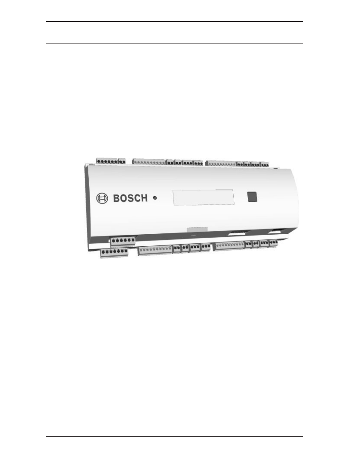
Description
The APC-AMC2-4WCF (also called AMC2-4W, AMC2, or
controller) is equipped with four independent interfaces for
Wiegand type readers. It is able to control two doors with a
reader in each direction and up to four doors with a reader in
one direction only.
Figure 3.1: The Access Modular Controller AMC2-4W
All necessary information for access verification is stored in a
battery buffered on-board memory and a Compact Flash (CF)
memory card. This guarantees autonomous access decisions and
complete access registrations even if the management host
system is offline. The built in compact flash adapter provides
adequate storage capability for cardholders and events.
The AMC2-4W electronics are completely covered by a plastic
housing. The liquid crystal display provides all important status
information.
3
3.1
12 en | Introduction
Access Modular
Controller
2016-11 | AMC2-4W | Bosch Sicherheitssysteme
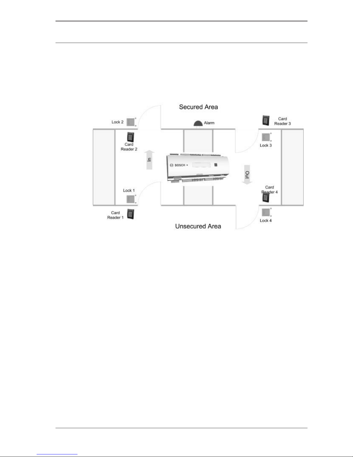
Using the AMC2-4W gives you the full functionality and the
offline capability of a complete access control system in each
room. This leads to an excellent reliability and a very high
redundancy without extra cost.
Figure 3.2: The AMC2-4W in a four door safety lock
The AMC2-4W can communicate upstream to the host computer
using RS-485 multi‑dropped, RS-232 or 10/100 Mbit/s Ethernet.
It has eight analog input devices and eight relay outputs. With
its analog input devices, the AMC2-4W verifies, for example, if a
lock is closed or open. The relay outputs can be used to activate
lock mechanisms if access is granted, or activate the burglar
alarm system if an intrusion or system alert is detected. If the
eight inputs and eight outputs on board are not enough to
configure the system, up to three additional extensions
(AMC2-8IOE, AMC2-16IE, or AMC2-16IOE) can be connected.
The extensions offer 8 or 16 additional inputs and outputs.
The setup procedure for an AMC2-4W is made very simple and
fast by the use of door templates. Once selected, all the inputs
and outputs are predefined. These settings can be changed to
choose every free contact of the controller or a connected
extension.
Access Modular
Controller
Introduction | en 13
Bosch Sicherheitssysteme 2016-11 | AMC2-4W |
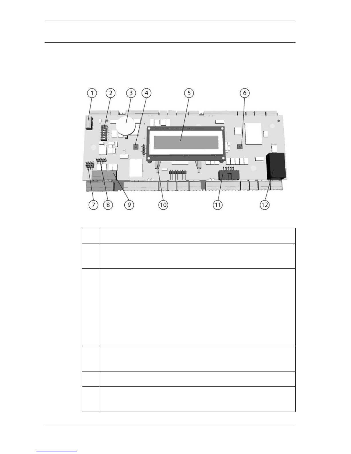
Equipment Configuration
Figure 3.3: Upper circuit board with display (top side)
1
(N.A.)
2 DIL switch for RS-485 address selection , protocol, and
RS-232/RS-485 selection.
3 Lithium battery for buffering of static RAM and real time
clock (RTC). The battery life is estimated at 10 years,
nevertheless an error message is generated if the voltage
sinks below a preset minimum level.
NOTICE: In order to avoid an error message caused by an
earlier voltage drop we suggest to replace the battery
every 8 years. Spare part: VARTA CR 2032 PCB.
4 Reset push button - reachable through the casing using a
screwdriver
5 Liquid Crystal Display
6 Push button, available on top of the housing, to select
different display modes
3.2
14 en | Introduction
Access Modular
Controller
2016-11 | AMC2-4W | Bosch Sicherheitssysteme
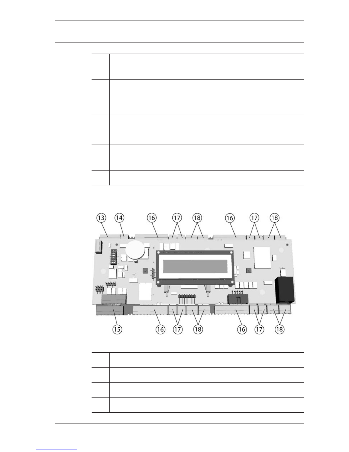
7 Jumper: Equalization of potential between different
systems and earth ground (shield)
8 Jumper: Interface selector RS-485 host connection,
RS-485 two wire or RS-485 four wire (depends on
external wiring)
9 Configurable RS-485 host interface
10 Docking port for compact flash memory
11 Configurable RS-232 host interface (ribbon cable
connector)
12 Configurable 10/100 Mbit/s Ethernet host interface
Figure 3.4: Overview - Interfaces
13
RS-485 extension module bus
14 External tamper contact
15 Connector for power supply
16 Wiegand interfaces for up to 4 card readers
Access Modular
Controller
Introduction | en 15
Bosch Sicherheitssysteme 2016-11 | AMC2-4W |
17 Connectors for eight analog inputs
18 Connectors for eight relay outputs
Notice!
All connectors, with the exception of the RS-232 and Ethernet
host interface, are pluggable screw clamp terminals.
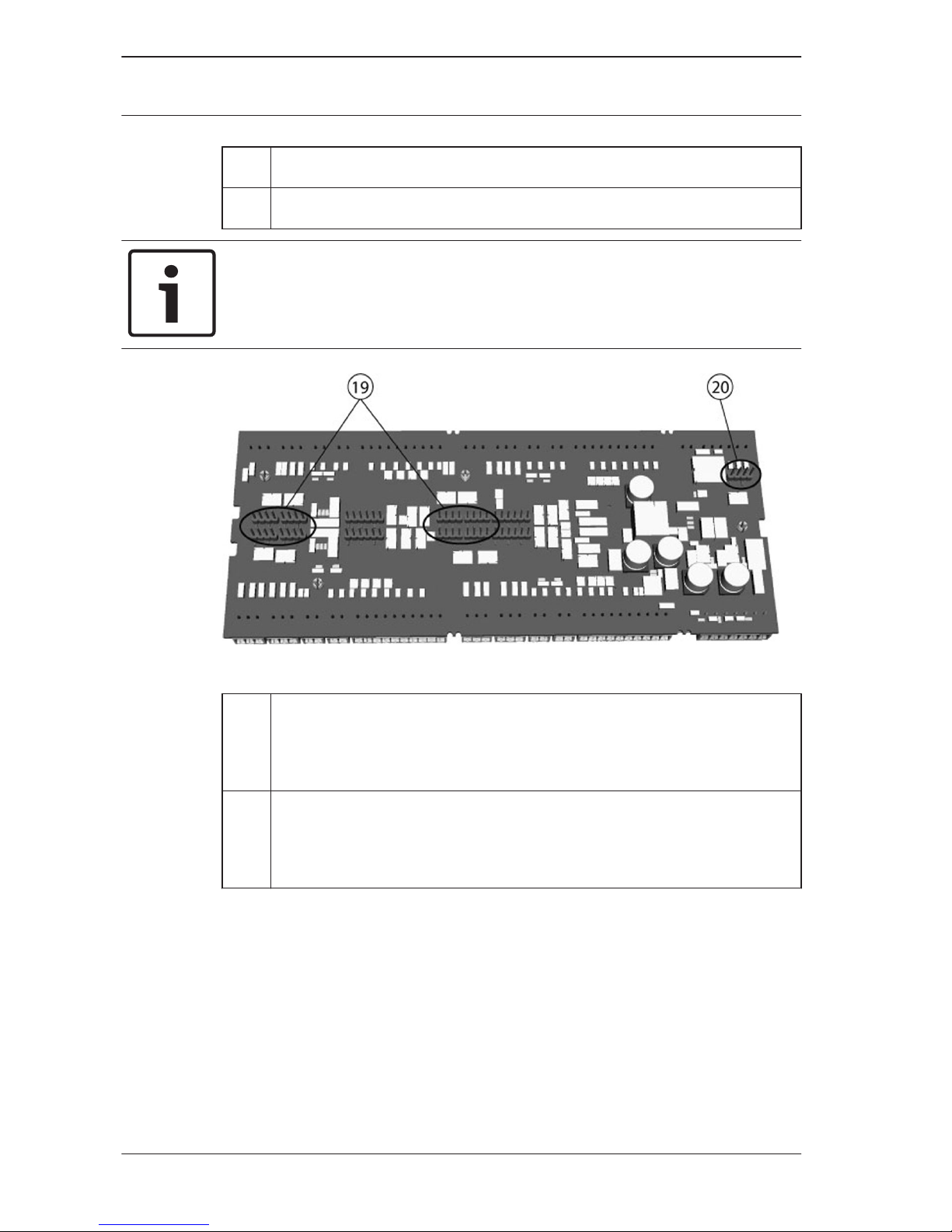
Figure 3.5: Jumper at the bottom side
19
Jumper for setting either voltage free relay output (“dry”
mode) or looped-in voltage from the AMC2 internal
power supply (“wet” mode).
20 Jumper: Equalization of potential between different
systems and earth ground (shield) for the extension
interface.
Performance Characteristics
– Intelligent access manager for 1 - 4 entrances (for example
doors, man traps, barriers)
– Host address selectable using DIL sliding switch.
– Four possible configurable host interfaces:
– Ethernet (= standard)
– RS-485 2-wire
– RS-485 4-wire
3.3
16 en | Introduction
Access Modular
Controller
2016-11 | AMC2-4W | Bosch Sicherheitssysteme
– RS-232
– Reader interfaces
– four Wiegand interfaces
– 8 relay outputs
– voltage free, power is supplied externally (dry mode)
– powered by internal power supply (wet mode)
– 8 analog inputs with internal power supply
– Battery buffered SRAM and real time clock (RTC)
– Pluggable Compact Flash card
– Liquid Crystal Display
– Transfer rate host interface RS-485: 38,4 kBit/s
– Transfer rate host interface RS-232: 38,4 kBit/s
– Transfer rate host interface Ethernet: 10/100 Mbit/s
– Transfer rate to the extension interface: 9,6 kBit/s
– Self regulating transmit/receive switching
– Supply voltage: 10 V to 30 Vdc,
– Max current load: 5A
– Tamper contact for external covers
Notice!
If an external power supply is used, this should also guarantee
an uninterruptable power supply (UPS). Example: Bosch power
supply APS-PSU-60 (F.01U.282.970).
System Overview
The Access Controller AMC2-4W is connected between the
management host system and different peripheral devices. By
default, a management host system is connected using Ethernet.
A management host connection using RS-485 or RS-232 is also
possible. Corresponding to the available interfaces, one AMC2
can be connected to each COM port using RS-232 mode. In
RS-485 mode, up to eight access controllers can be combined
on one party line.
3.4
Access Modular
Controller
Introduction | en 17
Bosch Sicherheitssysteme 2016-11 | AMC2-4W |
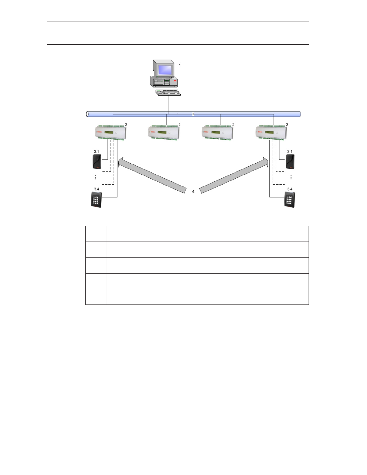
Figure 3.6: System overview
1 =
Host
2 = AMC2-4W
3 = Wiegand reader (1 - 4)
4 = Communication and power supply
5 = Ethernet
System configurations for Access Control applications.
– The minimum configuration consists of:
– one PC with system software,
– one AMC2 controller,
– one AMC power supply,
– one AMC enclosure.
– The maximum configuration depends on the system
software,
– Each AMC2-4W controller can be extended with an
AMC2-4WE extension module.
18
en | Introduction
Access Modular
Controller
2016-11 | AMC2-4W | Bosch Sicherheitssysteme

Using Wiegand reader interfaces, up to four peripheral devices
can be connected to each AMC2-4W. The interfaces are point-topoint connections, meaning that only one reader can be
connected to one interface.
The extension interface supports up to three additional I/O
boards (AMC2-8IOE, AMC2-16IE, or AMC2-16IOE)and one
AMC2-4WE. All extension boards are controlled by the AMC2
and are freely combinable.
Access Modular
Controller
Introduction | en 19
Bosch Sicherheitssysteme 2016-11 | AMC2-4W |
Installing
Notice!
To build an UL approved system refer the documentation
contained in the folder titled "_UL" on the delivered CD.
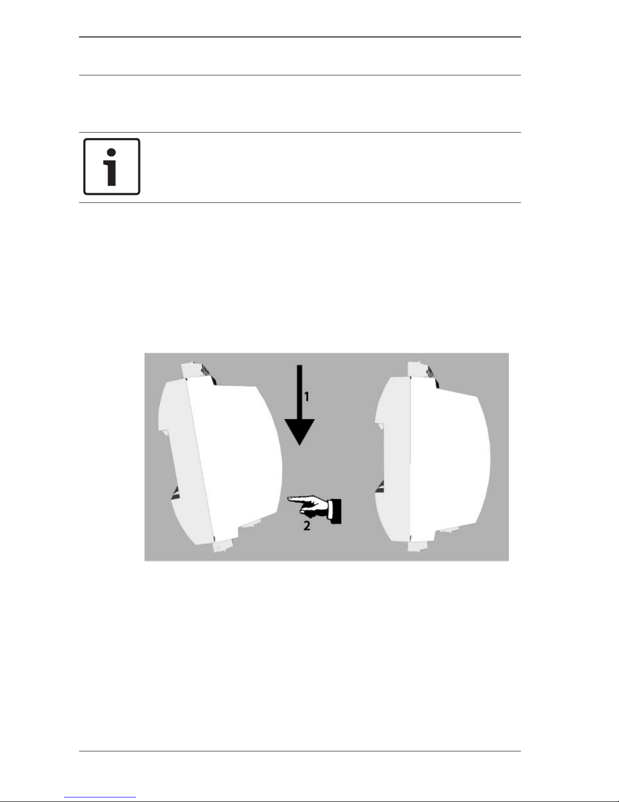
Mounting
The AMC2-4W can be attached on a standard 35 mm (1.377 in.)
mounting rail using a snap-in mechanism. Attach the AMC2-4W
into the upper edge of the mounting rail [1], then push down
the device and snap it onto the rail by pushing it towards the
back [2].
Figure 4.1: Mounting the AMC2 on a mounting rail
4
4.1
20 en | Installing
Access Modular
Controller
2016-11 | AMC2-4W | Bosch Sicherheitssysteme
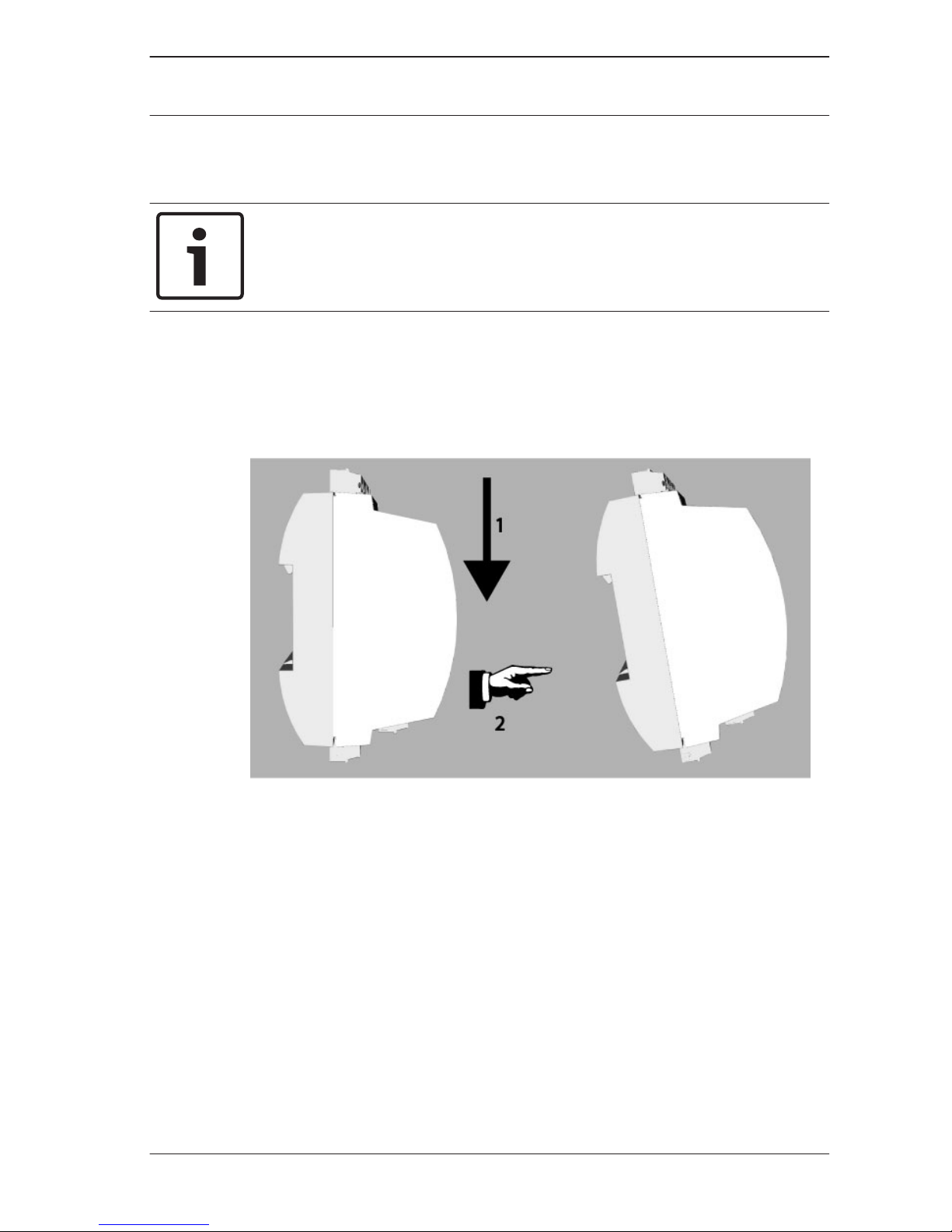
Unmounting
Notice!
To remove the AMC2-4W from a mounting rail, first remove all
pluggable connectors.
Push down the AMC2-4W until the lower edge snaps out of the
mounting rail [1]. Pull the lower end of the AMC2-4W from the
mounting rail [2].
Figure 4.2: Unmounting the AMC2 from a mounting rail
4.2
Access Modular
Controller
Installing | en 21
Bosch Sicherheitssysteme 2016-11 | AMC2-4W |
 Loading...