

Page 1
BM 1609929Y07 10-10:BM 1609929Y07 10-10 1/18/11 10:05 AM Page 1
IMPORTANT: IMPORTANT : IMPORTANTE:
Read Before Using Lire avant usage Leer antes de usar
Operating/Safety Instructions
Consignes de fonctionnement/sécurité
Instrucciones de funcionamiento y seguridad
1821
1821D
Call Toll Free for
Consumer Information
& Service Locations
Pour obtenir des informations
et les adresses de nos centres
de service après-vente,
appelez ce numéro gratuit
Llame gratis para
obtener información
para el consumidor y
ubicaciones de servicio
1-877-BOSCH99 (1-877-267-2499) www.boschtools.com
For English Version Version française Versión en español
See page 2 Voir page 18 Ver la página 34
Page 2

BM 1609929Y07 10-10:BM 1609929Y07 10-10 1/18/11 10:05 AM Page 2
General Power Tool Safety Warnings
WARNING
!
to follow the warnings and instructions may
result in electric shock, fire and/or serious
injury.
SAVE ALL WARNINGS AND
INSTRUCTIONS FOR FUTURE
The term “power tool” in the warnings refers to
your mains-operated (corded) power tool or
battery-operated (cordless) power tool.
a) Ke ep wo rk ar ea cl ean and we ll li t.
Cluttered or dark areas invite accidents.
b) Do not operate power tools in explosive
atmospheres, such as in the presence of
flammable liquids, gases or dust. Power
tools create sparks which may ignite the
dust or fumes.
c) Keep children and b ystanders away
while operating a power tool. Distractions
can cause you to lose control.
a) Power tool plugs must match the outlet.
Never modify the plug in any way. Do not
use any adapte r plugs wit h earth ed
(grounded) power tools. Unmodified plugs
and matching outlets will reduce risk of
electric shock.
b) Avo id body con tact with ear thed or
gr oun ded su rfa ces suc h as pipes,
radiators, ranges and refrigerators. There
is an increased risk of electric shock if your
body is earthed or grounded.
c) Do not expose power tools to rain or wet
conditions. Water entering a power tool will
increase the risk of electric shock.
d) Do not abuse the cord. Never use the
cord for carrying, pulling or unplugging
the power tool. Keep cord away from
heat, oil, sharp edges or moving parts.
Damaged or entangled cords increase the
risk of electric shock.
e) When operating a power tool outdoors,
us e an exten sio n cord sui tab le for
outdoor use. Use of a cord suitable for
outdoor use reduces the risk of electric
shock.
Read al l safety wa rn in gs
and all instructions. Failure
REFERENCE
1) Work area safety
2) Electrical safety
f) If operating a power tool in a d amp
location is unavoidable, use a Ground
Fault Circuit Interrupter (GFCI) protected
supply. Use of an GFCI reduces the risk of
electric shock.
3) Personal safety
a) Stay alert, watch what you are doing and
use common sense when operating a
power tool. Do not use a power tool while
you are tired or under the influence of
drugs, alcohol or medication. A moment
of inattention while operating power tools
may result in serious personal injury.
b) Use per sonal protect ive equipme nt.
Always wear eye protection. Protective
equipment such as dust mask, non-skid
safety shoes, hard hat, or hearing protection
used for appropriate conditions will reduce
personal injuries.
c) Prevent unintentional starting. Ensure
the switch is in the off-position before
connecting to power source and / or
battery pack, picking up or carrying the
tool. Carrying power tools with your finger
on the switch or energizing power tools that
have the switch on invites accidents.
d) Remove any adjusting key or wrench
befo re turning th e power too l on. A
wrench or a key left attached to a rotating
part of the power tool may result in personal
injury.
e) Do not overreach. Keep proper footing
and balance at all times. This enables
be tte r con tro l of the p owe r tool i n
unexpected situations.
f) Dr ess pro per ly. Do not wear loose
clot hing or je welry . Ke ep you r hair,
clothing and gloves away from moving
parts. Loose clothes, jewelry or long hair
can be caught in moving parts.
g) If de vic es a re pr ovi ded for the
co nne cti on o f dust ext raction an d
collection facilities, ensure these are
connected and properly used. Use of dust
collection can reduce dust-related hazards.
4) Power tool use and care
a) Do not force the power tool. Use the
correct power tool for your application.
The correct power tool will do the job better
and safer at the rate for which it was designed.
-2-
Page 3

BM 1609929Y07 10-10:BM 1609929Y07 10-10 1/18/11 10:05 AM Page 3
b) Do not use the power tool if the switch
does not turn it on and off. Any power tool
that cannot be controlled with the switch is
dangerous and must be repaired.
c) Disconn ect the plug from the power
source and/or the battery pack from the
po wer to ol bef ore ma kin g any
adjustments, changing accessories, or
storing power tools. Such preventive
safety measures reduce the risk of starting
the power tool accidentally.
d) Store idle power tools out of the reach of
ch ild ren and do not allo w person s
unfamiliar with the power tool or these
instructions to operate the power tool.
Power tools are dangerous in the hands of
untrained users.
e) Ma int ain power to ols . Ch eck for
misalignment or binding of moving parts,
br eak age o f parts and a ny other
conditio n that may affect the p ower
Power Tool-Specific Safety Warnings
Safety Warnings Common for Grinding,
Sanding, Wire Brushing, and Abrasive
Cutting-Off Operations:
a) This power tool is intended to function
as a grinder, sander, wire brush or cutof f tool . Rea d all sa fety warn ings ,
in stru ctio ns, il lust rati ons an d
specifications provided with this power
tool. Failure to follow all instructions listed
below may result in electric shock, fire
and/or serious injury.
b) This power tool is not recommended for
polishing. Operations for which the power
tool was not designed may create a hazard
and cause personal injury.
c) Do not use accessories which are not
specifically designed and recommended
by the tool manufacturer. Just because
the accessory can be attached to your
po wer tool , it doe s not a ssur e saf e
operation.
d) The rated speed of the accessory must
be at least equal to the maximum speed
marked on the power tool. Accessories
running faster than their RATED SPEED
can break and fly apart.
tool’s operation. If damaged, have the
power tool repaired before use. Many
accidents are caused by poorly maintained
power tools.
f) Keep cutting to ols sharp and cle an.
Properly maintained cutting tools with sharp
cutting edges are less likely to bind and are
easier to control.
g) Use the power tool, accessories and tool
bi ts etc. in acc ord anc e with these
instructions, taking into account the
working conditions and the work to be
pe rfo rme d. Use of the p owe r too l for
operations different from those intended
could result in a hazardous situation.
5) Service
a) Have your power too l serv iced by a
qu ali fie d repa ir person usi ng onl y
identical replacement parts. This will
ensure that the safety of the power tool is
maintained.
e) The outside diameter and the thickness
of your accessory must be within the
ca paci ty rat ing of your p ower t ool.
Incorrectly sized accessories cannot be
adequately guarded or controlled.
f) Th e arbo r siz e of whe els, flang es,
backing pads or any other accessory
must properly fit the s pin dle of the
power tool. Accessories with arbor holes
that do not match the mounting hardware of
the pow er too l will run out of balance,
vibrate excessively and may cause loss of
control.
g) Do not use a damaged accessory. Before
each use inspect the accessory such as
abrasive wheels for chips and cracks,
backing pad for cracks, tear or excess
wear, wire brush for loose or cracked
wire s. I f power tool or acc essor y is
dropped, inspect for damage or install an
undamaged accessory. After inspecting
and installing an accessory, position
yourself and bystanders away from the
plane of the rotating accessory and run
the power tool at maximum no -load
sp eed for on e minut e. Damaged
accessories will normally break apart during
this test time.
-3-
Page 4

BM 1609929Y07 10-10:BM 1609929Y07 10-10 1/18/11 10:05 AM Page 4
h) Wear personal protective equipment.
Depe nding o n appli catio n, use f ace
shield, safety goggles or safety glasses.
As appropriate, wear dust mask, hearing
protectors, gloves and workshop apron
capable of stopping small abrasive or
workpiece fragments. The eye protection
must be capable of stopping flying debris
generated by various operations. The eye
protection must be capable of stopping flying
debris generated by various operations. The
dust mask or respirator must be capable of
fi ltr ati ng par tic les ge nerated by your
operation. Prolonged exposure t o high
intensity noise may cause hearing loss.
i) Keep bystanders a safe distance away
from work area. Anyone entering the
work area must wear personal protective
equipment. Fragments of workpiece or of a
broken accessory may fly away and cause
injury beyond immediate area of operation.
j) Hold power tool by insulated gripping
su rfa ces only , w hen perf orming an
operation where the cutting accessory
may contact hidden wiring or its own
cord. Cutting accessory contacting a “live”
wire may make exposed metal parts of the
power tool “live” and shock the operator.
k) Position the cord clear of the spinning
accessory. If you lose control, the cord may
be cut or snagged and your hand or arm
may be pulled into the spinning accessory.
l) Never lay the power tool down until the
accessory has come to a complete stop.
The spin ning ac ces sory may grab the
surface and pull the power tool out of your
control.
m)Do not run the power tool while carrying
it at your side. Accidental contact with the
sp inn ing a cce sso ry could snag y our
clothing, pulling the accessory into your
body.
n) Regularly clean the power to ol ’s air
vents. The motor’s fan will draw the dust
in sid e the hou sin g and excessi ve
accumulation of powdered metal may cause
electrical hazards.
o) Do not ope rat e the pow er tool n ear
flammable materials. Sparks could ignite
these materials.
p) Do not use accessories that require
liquid coolants. Using water or other liquid
coolants may res ul t in electrocution or
shock.
Kickback and Related Warnings
Kickback is a sudden reaction to a pinched or
snagged rotating wheel, backing pad, brush or
any other accessory. Pinching or snagging
causes rapid stalling of the rotating accessory
which in turn causes the uncontrolled power
tool to be forced in the direction opposite of the
accessory’s rotation at the point of the binding.
For example, if an abrasive wheel is snagged
or pinched by the workpiece, the edge of the
wheel that is entering into the pinch point can
dig into the surface of the material causing the
wheel to climb out or kickout. The wheel may
either jump toward or away from the operator,
de pen din g o n dire cti on of th e w hee l’s
movement at the point of pinching. Abrasive
wheels may also break under these conditions.
Kickback is the result of power tool misuse
and/or i ncorrec t op erating procedur es o r
conditions and can be avoided by taking proper
precautions as given below.
a) Maintain a firm grip on the power tool
and position your body and arm to allow
you to resist kickback forces. Always use
au xil iar y hand le, if prov ide d, for
ma xim um control ov er kic kback o r
torque re action during start-up. The
operator can control torque reactions or
kickback forces, if proper precautions are
taken.
b) Never place your hand near the rotating
accessory. Accessory may kickback over
your hand.
c) Do not position your body in the area
where power tool will move if kickback
occurs. Kickback will propel the tool in
direction opposite to the wheel’s movement
at the point of snagging.
d) Use special care when working corners,
sharp edges etc. Avoid bouncing and
snagging the accessory. Corners, sharp
edges or bouncing have a tendency to snag
the rotating accessory and cause loss of
control or kickback.
e) Do not attach a saw chain woodcarving
blade or toothed saw blade. Such blades
create frequent kickback and loss of control.
Safety Warnings Specific for Grinding and
Abrasive Cutting-Off Operations:
a) Us e o nly whe el t ype s th at are
recommended for your power tool and
the sp eci fic gua rd designed for the
selected wheel. Wheels for which the
-4-
Page 5

BM 1609929Y07 10-10:BM 1609929Y07 10-10 1/18/11 10:05 AM Page 5
power tool was not designed cannot be
adequately guarded and are unsafe.
b) The guard must be securely attached to
th e power tool and positioned for
maximum safety, so the least amount of
wheel is exposed towards the operator.
The guard helps to protect operator from
broken wheel fragments and accidental
contact with wheel.
c) Wh eel s must be us ed onl y f or
re com men ded ap pli cat ion s. For
example: do not grind with the side of
cut-off wheel. Abrasive cut-off wheels are
intended for peripheral grinding, side forces
applied to these wheels may cause them to
shatter.
d) Always use undamaged wheel flanges
that are of correct size and shape for
your selected wheel. Proper wheel flanges
su ppo rt the wh eel th us red uci ng the
possibility of wheel breakage. Flanges for
cut-off wheels may be different from grinding
wheel flanges.
e) Do not use worn down wheel s fr om
larger power tools. Wheel intended for
larger power tool is not suitable for the
higher speed of a smaller tool and may
burst.
Additional Safety Warnings Specific for
Abrasive Cutting-Off Operations:
Do not attempt to cut large stock or sheets
of metal as this machine is not designed to
be a dedicated cut-off machine.
a) Do not “jam” the cut-off wheel or apply
excessive pressure. Do not attempt to
ma ke an e xcessive de pth o f cut.
Overstressing the whee l increas es the
loading and susceptibility to twisting or
binding of the wheel in the cut and the
possibility of kickback or wheel breakage.
b) Do not position your body in line with
and behind the rotating wheel. When the
wheel, at the point of operation, is moving
away from your body, the possible kickback
may propel the spinning wheel and the
power tool directly at you.
c) Wh en whe el is bind ing or whe n
interrupting a cut for any reason, switch
off the power tool and hold the power
tool motionless until the wheel comes to
a co mpl ete stop. Neve r attempt to
remove the cut-off wheel from the cut
while the wheel is in motion otherwise
kickback may occur. Investigate and take
corrective action to eliminate the cause of
wheel binding.
d) Do not restart the cutting operation in the
workpiece. Let the wheel reach full speed
and carefully reenter the cut. The wheel
may bind, walk up or kickback if the power
tool is restarted in the workpiece.
e) Su ppo rt panels or any over siz ed
workpiece to minimize the risk of wheel
pinching and kickback. Large workpieces
te nd to sag under thei r own weig ht.
Su ppo rts must be placed under t he
workpiece near the line of cut and near the
edge of the workpiece on both sides of the
wheel.
f) Us e ext ra caut ion w hen m aking a
“pocket cut” into existing walls or other
blind areas. The protruding wheel may cut
gas or water pipe s, electrical wiring or
objects that can cause kickback.
Do not use type 1 abrasive wheels designed
for straight grinding.
Safety Warnings Specific for Sanding
Operations:
a) Do not use excessively oversized sanding
di sc p ape r. F ollow manuf act ure r’s
re com men dat ion s, whe n se lec tin g
sanding paper. Larger sanding pap er
extending beyond the sanding pad presents
a lacer ati on ha zar d and may cau se
snagging, tearing of the disc or kickback.
Safety Warnings Specific for Wire Brushing
Operations:
a) Be aware that wire bristles are thrown by
th e br ush even dur ing o rdi nary
operation. Do not overstress the wires
by applying excessive load to the brush.
The wire bristles can easily penetrate light
clothing and/or skin.
b) If the use of a guard is recommended for
wi re brus hing , d o n ot a llo w any
interference of the wire wheel or brush
with the guard. Wire wheel or brush may
expand in diameter due to work load and
centrifugal forces.
-5-
Page 6

BM 1609929Y07 10-10:BM 1609929Y07 10-10 1/18/11 10:05 AM Page 6
Additional Safety Warnings
GFCI and personal protection devices like
electrician’s rubber gloves and footwear will
further enhance your personal safety.
Do not use AC only rated tools with a DC
power supply. While the tool may appear to
work, the electrical components of the AC
rated tool are likely to fail and create a hazard
to the operator.
Keep handles dry, clean and free from oil
and grease. Slippery hands cannot safely
control the power tool.
Use clamps or other practical way to secure
and sup port t he wor kpiece to a sta ble
platform. Holding the work by hand or against
your body is unstable and may lead to loss of
control.
Develop a periodic maintenance schedule
for y our tool. When cl ea ning a tool be
careful not to disassemble any portion of
th e tool since internal wires may be
misplaced or pinched or safety guard return
sp rin gs may be imp rop erl y mounted.
Certain cleaning agents such as gasoline,
carb on t etrac hloride, ammonia, etc. may
damage plastic parts.
Risk of injury to user. The power cord must only
be serviced by a Bosch Factory Service Center
or Autho rized Bosch Service Station.
Us e hand gu ard w hen sanding and
brushing.
Do not use type 1 wheels for face grinding.
Side forces applied to type 1 wheels may cause
them to shatter or burst.
WARNING
!
drilling, and other construction activities
contains chemicals known to cause cancer,
birth defects or other reproductive harm.
Some examples of these chemicals are:
• Lead from lead-based paints,
• Crystalline silica from bricks and cement and
other masonry products, and
• Arsen ic and chr omium from chemica ll ytreated lumber.
Yo u r r i sk f rom t hese exp o sure s va ries ,
depending on how often you do this type of
work . To redu ce your e xpo sure to t hese
chemicals: work in a well ventilated area, and
work with approved safety equipment, such as
those dust masks that are specially designed
to filter out microscopic particles.
Some dust created by power
sanding, sawing, grinding,
-6-
Page 7
0
BM 1609929Y07 10-10:BM 1609929Y07 10-10 1/18/11 10:05 AM Page 7
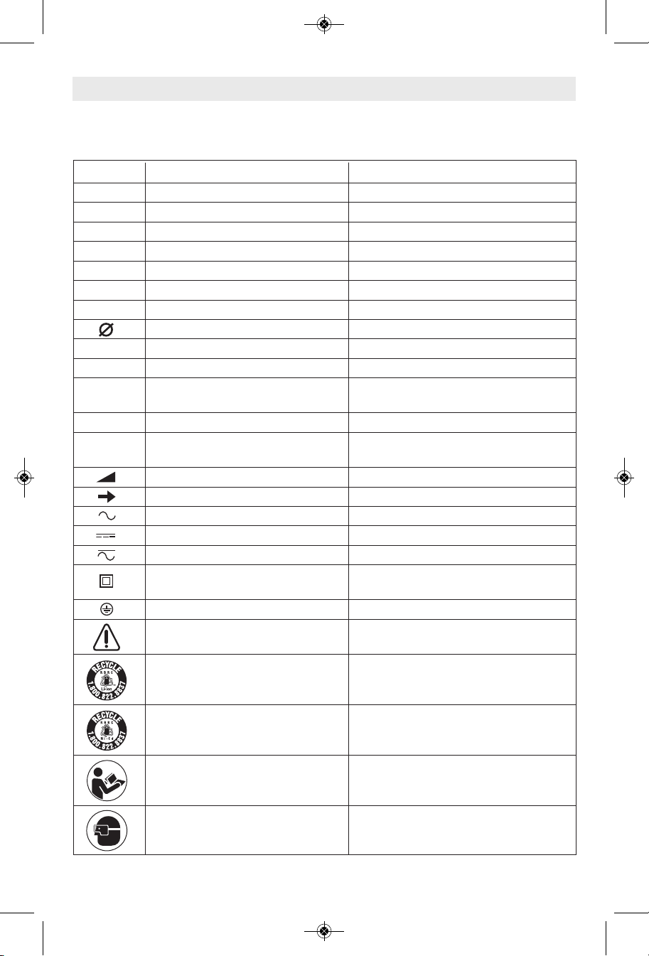
Symbols
IMPORTANT: Some of the following symbols may be used on your tool. Please study them
and learn their meaning. Proper interpretation of these symbols will allow you to operate the
tool better and safer.
Symbol Name Designation/Explanation
V Volts Voltage (potential)
A Amperes Current
Hz Hertz Frequency (cycles per second)
W Watt Power
kg Kilograms Weight
min Minutes Time
s Seconds Time
Diameter Size of drill bits, grinding wheels, etc.
n
0
n Rated speed Maximum attainable speed
.../min Revolutions or reciprocation Revolutions, strokes, surface speed,
0 Off position Zero speed, zero torque...
1, 2, 3, ... Selector settings Speed, torque or position settings.
I, II, III, Higher number means greater speed
No load speed Rotational speed, at no load
per minute orbits etc. per minute
Infinitely variable selector with off Speed is increasing from 0 setting
Arrow Action in the direction of arrow
Alternating current Type or a characteristic of current
Direct current Type or a characteristic of current
Alternating or direct current Type or a characteristic of current
Class II construction Designates Double Insulated
Construction tools.
Earthing terminal Grounding terminal
Warning symbol Alerts user to warning messages
Li-ion RBRC seal Designates Li-ion battery recycling
program
Ni-Cad RBRC seal Designates Ni-Cad battery recycling
program
Read manual symbol Alerts user to read manual
Wear eye protection symbol Alerts user to wear eye protection
-7-
Page 8
BM 1609929Y07 10-10:BM 1609929Y07 10-10 1/18/11 10:06 AM Page 8
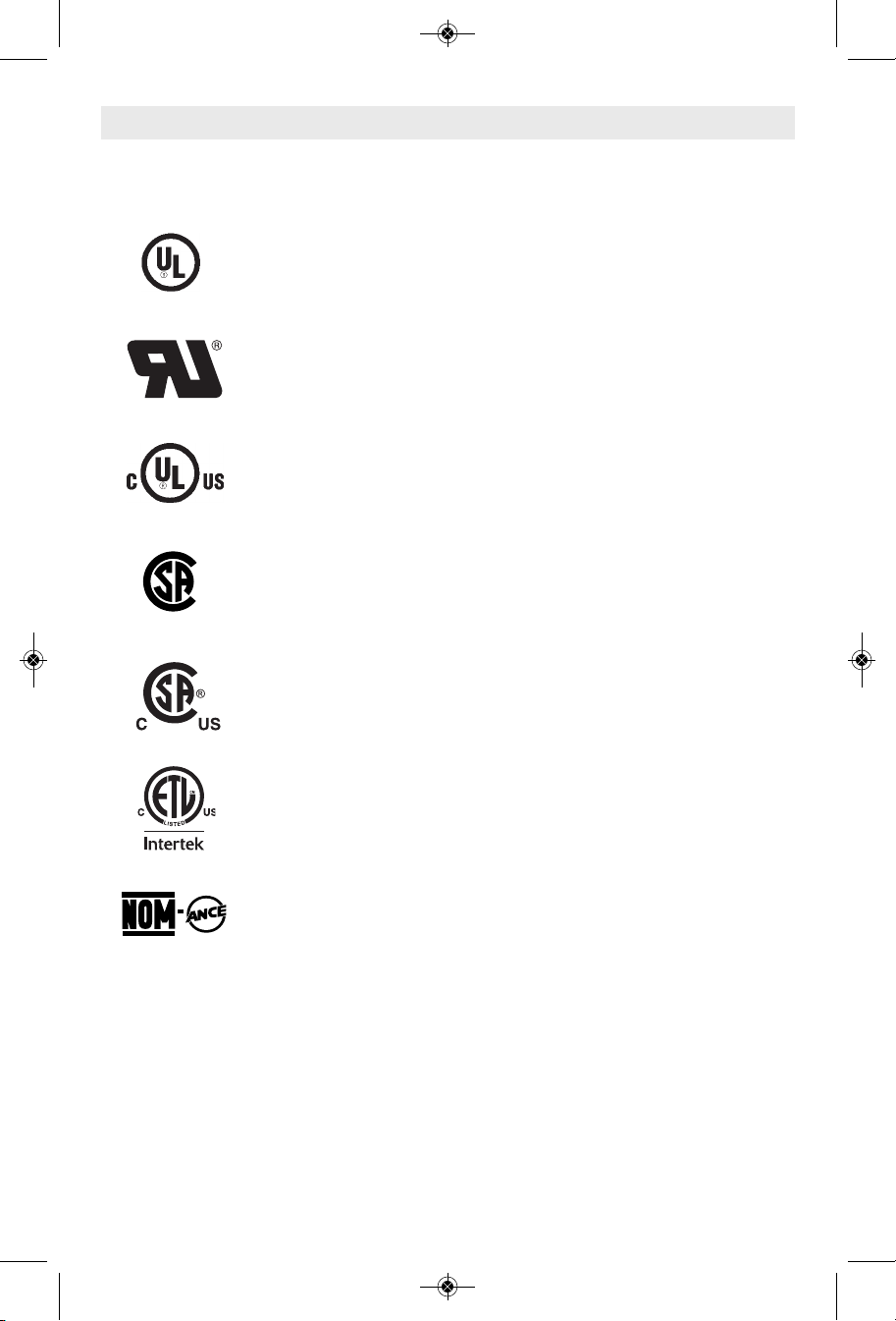
Symbols (continued)
IMPORTANT: Some of the following symbols may be used on your tool. Please study them
and learn their meaning. Proper interpretation of these symbols will allow you to operate the
tool better and safer.
This symbol designates that this tool is listed by Underwriters Laboratories.
This symbol designates that this tool is recognized by Underwriters Laboratories.
This symbol designates that this tool is listed by Underwriters Laboratories,
to United States and Canadian Standards.
This symbol designates that this tool is listed by the Canadian Standards
Association.
This symbol designates that this tool is listed by the Canadian Standards
Association, to United States and Canadian Standards.
This symbol designates that this tool is listed by the Intertek Testing
Services, to United States and Canadian Standards.
This symbol designates that this tool complies to NOM Mexican Standards.
-8-
Page 9
BM 1609929Y07 10-10:BM 1609929Y07 10-10 1/18/11 10:06 AM Page 9
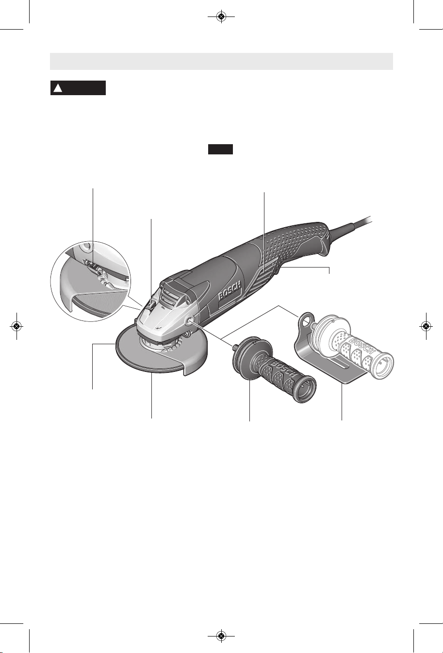
Functional Description and Specifications
WARNING
!
measures reduce the risk of starting the tool accidentally.
Di scon n ect th e p l ug from th e p ower so urce be for e makin g any
assembly, adjustments or changing accessories. Such preventive safety
Angle Grinders
FIG. 1
GUARD
RELEASE / ADJUSTMENT
BUTTON
SPINDLE LOCK
VENTILATION
OPENINGS
PADDLE
SWITCH
GRINDING
WHEEL
WHEEL
GUARD
Model number 1821, 1821D
* Rated speed n 11,000/min
* Max. abrasive wheel diameter 5" (125 mm)
Spindle thread 5/8"-11 UNC
Max. spindle length 9/16"
Max. wire wheel 4" Dia.
Max. wire cup brush 3" Dia.
* Max. sanding disc 5" Dia.
VIBRATION
CONTROL
SIDE HANDLE
-9-
HAND GUARD
(Optional Accessory)
Page 10
BM 1609929Y07 10-10:BM 1609929Y07 10-10 1/18/11 10:06 AM Page 10
Functional Description and Specifications (Continued)
Model number 1821, 1821D
Max. type 1 and 27 grinding wheels 5" Dia.
* Max. type 1A and 27A cutting wheel 5" Dia.
* Max. flap disc 5" Dia.
Accessory speed rating must be equal to or greater than the tool’s speed rating. Do not
NOTE: Not recommended for use with type 11 cup wheels.
* NOTE: For tool specifications refer to the nameplate on your tool.
exceed the recommended wheel diameter.
Assembly
WHEEL GUARD INSTALLATION
WARNING
!
grinding or cutting wheels. Always keep wheel
guard be tween you and your w ork w hile
grinding or cutting.
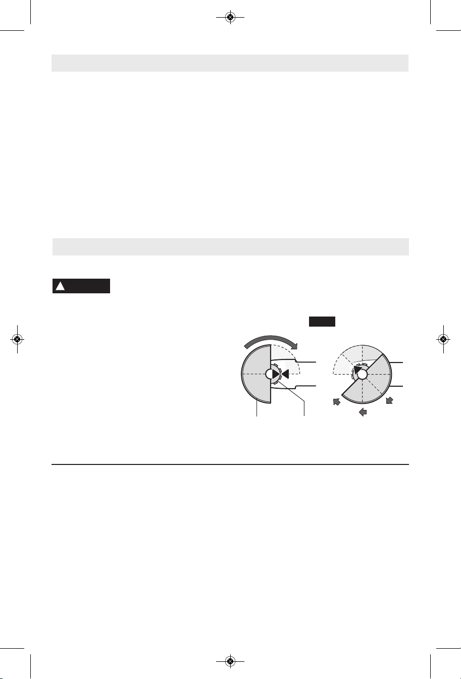
The position of the guard can be adjusted to
accommodate the operation being performed.
To attach wheel guard DISCONNECT tool
from power source.
Position wheel guard on spindle neck so that
the arrow on guard lines up with the arrow on
th e s pind le n eck. Rotat e w heel gu ard
clockwise 90º until it clicks in place (Fig. 2).
TO ADJUST GUARD: depress guard release
button (Fig. 1), rotate guard to desired position,
release button and let it click in place.
Wh eel gu ard must be
at tac hed w hen u sing disc
TO RE MOV E GUARD : De p res s relea se
button, rotate guard until arrow on guard lines
up with arrow on spindle neck, and remove
guard from spindle neck.
FIG. 2
WHEEL
GUARD
SPINDLE
NECK
LOCK NUT AND BACKING FLANGE
Your tool is equipped with a threaded spindle
for mounting ac ces sories. Always use the
supplied lock nut (and backing flange) that
has same thread size as spindle.
VIBRATION CONTROL SIDE HANDLE
The side handle is used to control and balance
the tool. The handle must be thread ed into the
fr ont ho usin g on eith er side o f t he tool ,
de pend ing on pe r s onal pr efe renc e and
comfort. Use the side handle for safe control
and ease of operation (Fig. 1).
The hand guard is to be used with backing
OPTIONAL HAND GUARD
pads, sanding discs and wire brushes to keep
fingers and hand away from work surface,
sharp edges, burrs and debris. When using the
optional hand guard accessory insert side
handle through hole in guard and then thread
into housing (Fig. 1).
Ensure that hand guard is positioned between
hand and backing pad, sanding disc or wire
brush.
-10-
Page 11
BM 1609929Y07 10-10:BM 1609929Y07 10-10 1/18/11 10:06 AM Page 11
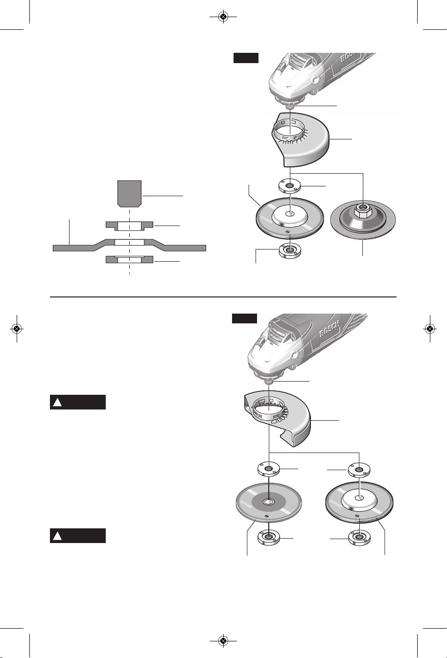
DISC GRINDING WHEEL ASSEMBLY
Disconnect tool from power source. Be sure
that wheel guard is in place for grinding. Place
BACKING FLANGE and GRINDING WHEEL
on the spindle. Thread on the lock nut and
tighten nut using the supplied lock nut wrench,
while holding the spindle lock in (Fig. 3).
TO REMOVE: Reverse procedure.
When using spin-on wheels, thread directly
onto the spindle.
TYPE 27
GRINDING
WHEEL
SPINDLE
BACKING
FLANGE
LOCK NUT
ABRASIVE TYPE 1A & 27A
WHEEL ASSEMBLY
Using the optional type 1A wheel guard, it is
possible to perform limited cutting on small
stock such as metal tubes, piping or rebar.
Do not attempt to cut large stock or sheets of
metal as this tool is not designed to be a
dedicated cutting tool.
WARNING
!
Always use type 1A protection
guard for cutting.
Disconnect tool from power source. Be sure
that wheel guard is in place for cutting.
Whe n us i n g m o u n t i ng w h e els, t hread
BACKING FLANGE onto spindle, then place
WHEEL on the spindle. Thread on the lock
nut and tighten nut using a lock nut wrench
provided with adapter kit, while holding the
spindle lock in (Fig. 4).
TO REMOVE: Reverse procedure.
TYPE 1 ABRASIVE
STRAIGHT GRINDING WHEELS
WARNING
!
Do not use type 1 abrasive
wh eels d esig ned f or
st raig ht/ d ie gr indi ng. Th is too l i s not
desi gned for use wit h type 1 a brasi ve
straight/die grinding wheels.
-11-
FIG. 3
TYPE 27
GRINDING
WHEEL
LOCK NUT
FIG. 4
TYPE 1A
(ISO41)
CUTTING
WHEEL
SPINDLE
TYPE 27
WHEEL GUARD
BACKING
FLANGE
TYPE 27 SPIN-ON
GRINDING WHEEL
SPINDLE
TYPE 1A
WHEEL GUARD
BACKING
FLANGE
LOCK NUT
TYPE 27A
CUTOFF
WHEEL
Page 12
BM 1609929Y07 10-10:BM 1609929Y07 10-10 1/18/11 10:06 AM Page 12
SANDING ACCESSORIES ASSEMBLY
WARNING
!
safe operating speed is not exceeded by the
nameplate speed of the tool.
WARNING
!
operatio ns. Always reinstall whe el gua rd
when converting back to grinding operations.
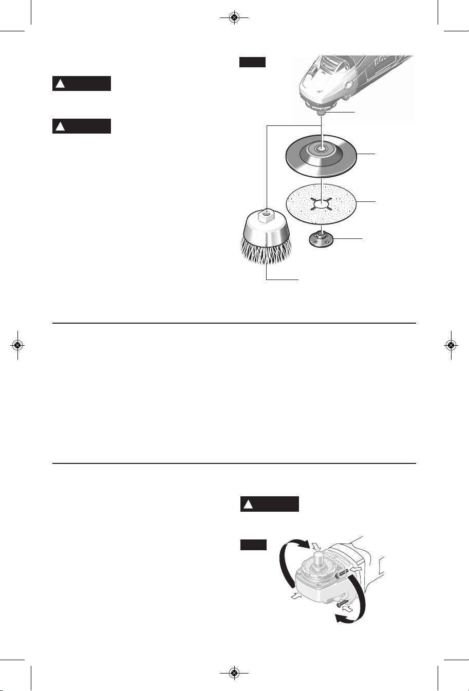
TO INSTALL BACKING PAD AND
Disconnect tool from power source.
Attach hand guard (Fig. 1). Set the tool on its
to p si d e ( s pind l e up ). P lace the rub b er
backing pad onto the spindle shaft. Center
the sanding disc on top of the backing pad.
In ser t the lock nut thr oug h the disc and
thread onto the spindle as far as you can with
your fingers. Press in the spindle lock, then
tighten the backing pad securely with lock nut
wrench (Fig. 5).
TO REMOVE: Reverse procedure.
Before assembling wire brush to this tool,
disconnect from the power source. Attach
han d guard ( F i g . 1) . Wire b r u s h es ar e
equipped with their own threaded hub, simply
thread on to spindle. Be sure to seat against
shoulder before turning tool “ON”.
TO REMOVE: Reverse procedure.
BACKING PAD
Before attaching a backing
pa d b e s u re its max imum
Whe e l guard m a y not be
use d for most sanding
SANDING DISC
WIRE BRUSH ASSEMBLY
FIG. 5
SPINDLE
BACKING
PAD
SANDING
DISC
LOCK NUT
WIRE
BRUSH
WIRE WHEEL ASSEMBLY
Before assembling wire wheel to this tool,
disconnect from the power source. Attach type
27 guard (Fig. 2). Wire wheeels are equipped
with their own threaded hub, simply thread on
to spindle. Be sure to seat against shoulder
before turning tool “ON”.
TO REMOVE: Reverse procedure.
MASONRY CUTTING WHEEL ASSEMBLY
Di s conn e ct pl ug fr o m po w er so urce.
Completely unscrew the four screws and
rotate the t ool head careful ly to the new
position without removing it from the housing.
For paddle switch tools, switch should face
“down” towards work surface. For slide switch
tools, slide should face “up” towards user, so
the tool can be used for long masonry cutting
applications. Screw in and tighten the four
screws again. (Fig. 6)
WARNING
!
grinding, sanding, brushing or metal cutting
applications.
FIG. 6
Return tool head to original
positi on w hen returni ng to
-12-
Page 13
BM 1609929Y07 10-10:BM 1609929Y07 10-10 1/18/11 10:06 AM Page 13
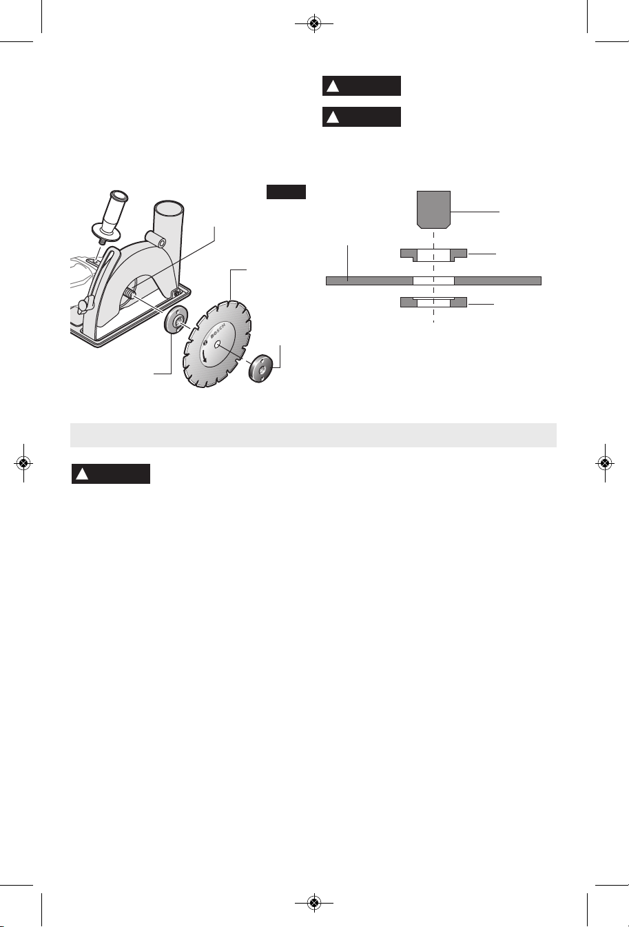
Install dust extraction guard with foot plate for
maso nry c utting app lication s so that t he
rotation of the wheel wil l be towards the
vacuum extraction port. Place BACKING
FLANGE and DRY DIAMOND WHEEL on the
spindle. Thread on the LOCK NUT and tighten
nut using the supplied lock nut wrench, while
holding the spindle lock in. (Fig. 7)
FIG. 7
SPINDLE
DRY
DIAMOND
WHEEL
LOCK
NUT
BACKING
FLANGE
Operating Instructions
!
WARNING
torque from the motor can cause the tool to twist.
Start the tool before applying to work and let
the tool come to full speed before contacting
the workpiece. Lift the tool from the work
before releasing the switch. DO NOT turn the
switch “ON” and “OFF” while the tool is under
load; this will greatly decrease the switch life.
"TRI-CONTROL" PADDLE SWITCH
The “Tri-Control” Paddle Switch enables the
operator to control the switch functions of
"Lock-OFF", "ON/OFF" and "Lock-ON".
TO UNLOCK SWITCH AND TURN TOOL
"ON": Push paddle lever FORWARD (toward
the spindle) then squeeze the paddle lever.
TO SWITCH TOOL "OFF": Release pressure
on paddle lever. The switch is spring loaded
and will return to "OFF" position automatically.
The "Lock-ON" feature, incorporated into the
paddle s witch, is a conve nience for long
operations.
Hold the tool with both hands
while starting the tool, since
(Models 1821 only)
WARNING
!
WARNING
!
cutting.
DRY
DIAMOND
WHEEL
TO LOCK SWITCH "ON": After paddle switch
has been activated push paddle lever completely
FORWARD and release paddle lever.
TO SWITCH TOOL "OFF": Squeeze and then
release paddle lever. The switch is spring
lo ade d and will r eturn to "OFF" p osi tio n
automatically.
The Paddle switch enables the operator to
control the switch functions of "Lock-OFF",
and "ON/OFF".
TO UNLOCK SWITCH AND TURN TOOL
"ON": Push paddle lever FORWARD (toward
the spindle) then squeeze the paddle lever.
TO SWITCH TOOL "OFF": Release pressure
on paddle lever. The switch is spring loaded
and will return to "OFF" position automatically.
Use only lock nut and flange
with equal diameters.
Do not u se water or o ther
cooling fluid with this tool for
SPINDLE
BACKING
FLANGE
LOCK NUT
PADDLE SWITCH WITH
"LOCK-OFF "FEATURE
(Model 1821D only
-13-
Page 14
BM 1609929Y07 10-10:BM 1609929Y07 10-10 1/18/11 10:06 AM Page 14
Grinding Operations
SELECTING GRINDING WHEELS
!
WARNING
ma ximu m safe opera ting s peed is not
exceeded by the nameplate speed of the
grinder. Do not exceed the recom mended
wheel diameter.
Grinding wheels should be carefully selected in
order to u se t he grinder most efficientl y.
Wh eels vary in type of ab rasi ve, bond ,
hardness, grit size and structure. The correct
type of wheel to use is determined by the job.
Use disc grinding wheels for fast grinding of
struct ural steel, heavy weld beads, steel
casting, st ai nl es s steel a nd other ferrous
metals.
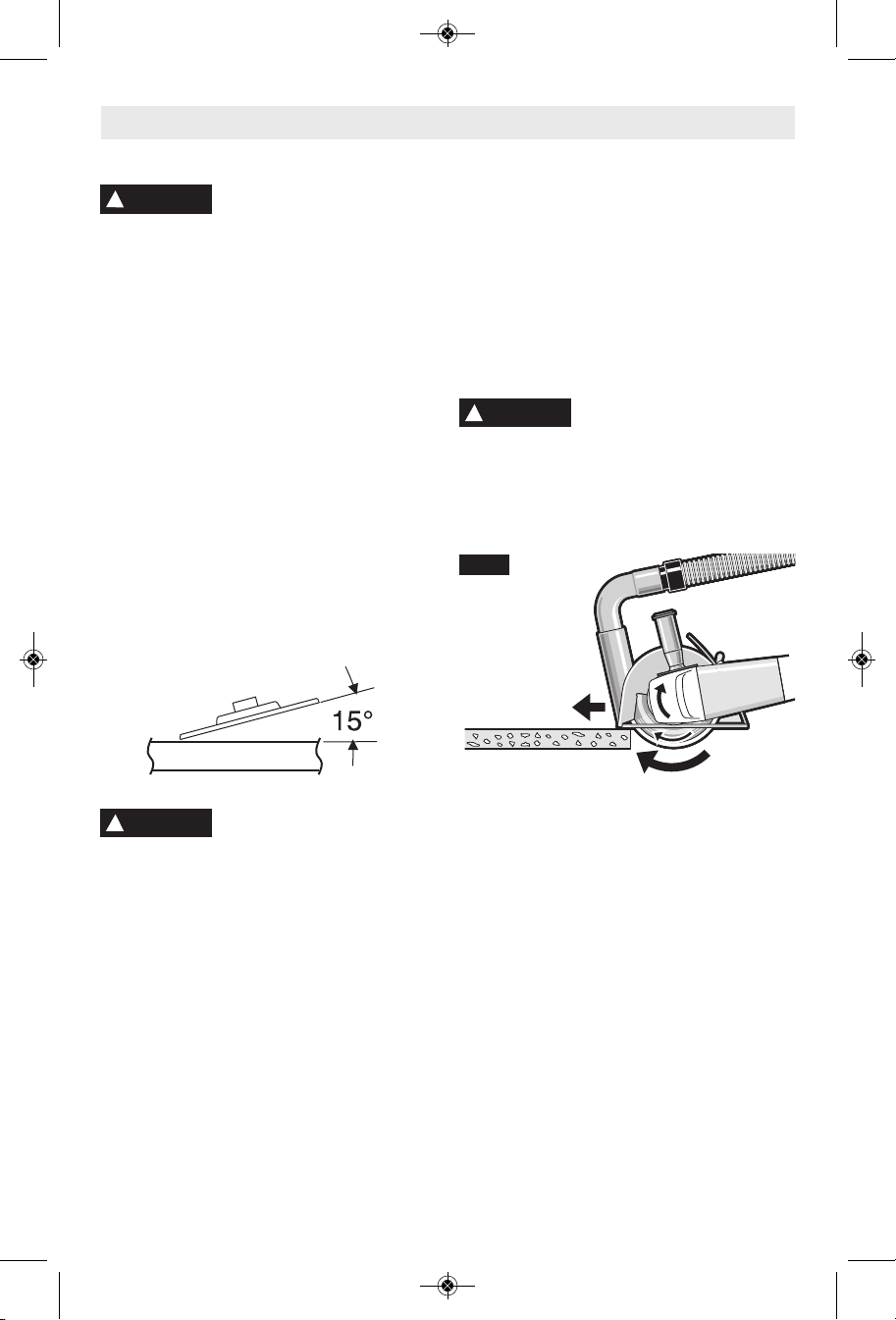
Efficient grinding is achieved by controlling the
pressure an d keep ing the angle between
wheel and workpiece at 10° to 15°. If the wheel
is flat, the tool is difficult to control. If the angle
is too steep, the pressure is concentrated on a
sm all are a ca usi ng b urni ng t o the w ork
surface.
Be fore using a grind ing
wh eel, be ce rta in th at its
DISC GRINDING WHEELS
GRINDING TIPS
Always follow precautions for kickback.
Do not apply side pressure to cutting wheel
to reduce wheel speed.
Th e tool shou ld alw ays be u sed so t hat
sparks are directed away from user.
Operate the tool only with dust extraction and
additionally wear a dust protection mask. The
vacuum used for this application must be
approved for the extraction of masonry dust.
Bosch sells suitable vacuum cleaners.
!
plate. The tool may be used only for dry
cutting. When cutting masonry use a dry
diamond wheel.
Always cut towards the dust extraction port
(Fig. 8).
FIG. 8
CUTTING MASONRY
WARNING
When cutting masonry always
use dust extraction with foot
WARNING
!
grinding action and put dangerous stresses on
the wheel.
When grinding with a new wheel be certain to
grind while pulling tool backwards until wheel
becomes rounded on its edge. New wheels
have sharp corners which tend to “bite” or cut
into work piece when pushing forward.
Using the optional type 1A wheel guard, it is
possible to perform limited cutting on small
stock such as metal tubes, piping or rebar.
When cutt ing , work w ith m ode rat e fee d,
adapted to the material being cut. Do not
exert side pressure onto the cutting disc, tilt
or oscillate the tool. When cutting profiles
and squar e bar , it is best to sta rt at the
smallest cross section.
Excessive or sudden pres-
sure on the wheel will slow
CUTTING METAL
Turn the tool on and place the front part of the
cutting guide on the workpiece. Slide the tool
with moderate rate of feed, adapted to the
material to be cut.
When doing deep cuts, it is best to cut in
several shallow passes.
When cutting especially hard material, e. g.,
concrete with high pebble content, the dry
diamond wheel can overheat and become
damaged. This is clearly indicated by circular
sparking of the rotating dry diamond wheel.
In this case, interrupt the cutting process and
allow the dry diamond wheel to cool by running
the tool for a short time at maximum speed
with no load.
Noticeable decreasing work progress and
circul ar s parking are ind ications of a dry
diamond wheel that has become dull. Briefly
cutting into abrasive materials (e. g. brick) can
resharpen the wheel again.
-14-
Page 15
BM 1609929Y07 10-10:BM 1609929Y07 10-10 1/18/11 10:06 AM Page 15
Sanding Operations
SELECTING SANDING DISC
Sanding discs are made of extremely hard
and sharp aluminum oxide grits, phenol-resin
bonded to a sturdy fiber backing for fast
heavy-duty service and long life. The discs
vary as to size and spacing of the abrasive
grits. OPEN COAT (type H) — used for soft
materials and on paint or varnish. CLOSED
COAT (type K) —used for metal, hardwood,
stone, marble and other materials.
Sanding discs range in grit from 16 (very
coarse) to 180 (very fine). To obtain best
results, select sanding discs carefully. Many
jobs require the use of several grit sizes and
at times both “open coat and closed coat”
discs are required to get the job done faster.
See chart for application examples.
Operation: Refinishing painted wood or metal surfaces.
REMARKS GRIT
To remove paint and to smooth Coarse
surface irregularities. 16-24-30
To smooth Medium
the rough sanding. 36-50-80
To remove scratches left by Fine
previous discs. 100-120
To smooth surfaces for painting, Very Fine
polishing or waxing. 150-180
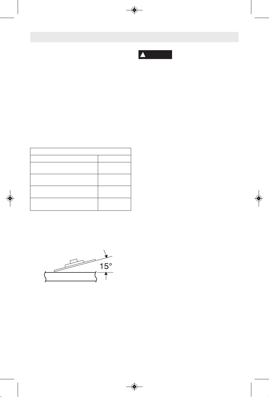
SANDING TIPS
For best results, tilt the Disc Sander at a 10°
to 15° angle while sanding so that only about
1" of the surface around the edge of the disc
contacts the work.
WARNING
!
If the disc (accessory) is held
flat or the back edge of the
disc comes in contact with the work, a violent
thrust to the side may result.
If sander is tilted too much, sanding action will
be t oo great a nd a roug h cut surf ace o r
gouging and snagging will result.
Guide the Disc Sander with crosswise strokes.
Be careful not to hold the sander in one spot
too long. Do not use a circular motion, as this
makes swirl marks. Test before use on scrap stock.
Do not force or apply pressure when sanding.
Use only the weight of the tool for pressure.
Excess pressure actually slows the tool down.
If faster stock removal is desired, change to a
coarser grit disc.
Remove gummy paint from metal with an
“open coat” disc. Sand until sparks start to
appear, then stop and change to a “closed
coat” disc to remove any remaining paint.
SANDING WOOD
When sanding wood the direction of the disc
motion at the contact point should parallel the
grain as much as possible. The rapid cut of
discs and the swirl type scratch pattern they
occasionally create generally prohibit their use
for producing the final finish.
Scratches and circular marks are usually the
result of using too coarse a grit. When changing
to a finer grit, move across the sand ing lines that
were made by a previous coarser disc.
SANDING METAL
When sanding automobiles or appliances,
wipe the metal clean with a non-flammable
solvent or commercial cleaner to remove all
wa x and greas e. By do ing this first, the
sanding discs will sand better and last longer.
For heavy duty work, use a coarse grit disc first.
Follow-up with a medium grit to remove scratches.
To produce smooth finish, use fine grit disc.
-15-
Page 16
BM 1609929Y07 10-10:BM 1609929Y07 10-10 1/18/11 10:06 AM Page 16
Wire Brush Operations
Wire brushes are intended to “clean” structural
st eel, cast ing s , sh eet meta l, stone and
concrete. They are used to remove rust, scale
and paint.
!
WARNING
when working corners, sharp edges etc. This
can cause loss of control and kick-back.
!
WARNING
even during ordinary operation. Do not
overstress the wires by applying excessive
load to the brush. The wire bristles can easily
penetrate light clothing and/or skin.
CORRECT:
Wire tips doing
the work.
CORRECT:
Wire tips doing
the work.
Avoid bouncing and snagging
th e wir e brush, espe cia lly
Be aware that wire bristles
are thrown by the brush
WIRE WHEEL BRUSH
WIRE CUP BRUSH
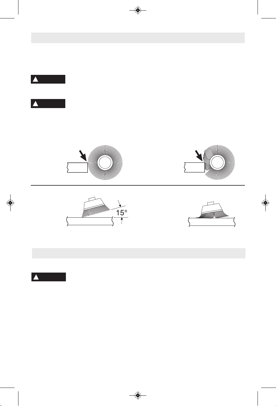
1. Remember, the tips of a wire brush do the
BRUSHING PRESSURE
work. Operate the brush with the lightest
pressure so only the tips of the wire come in
contact with the work.
2. If heavier pressures are used, the wires
will be overstressed, resulting in a wiping
action; and if this is continued, the life of the
brush will be shortened due to wire fatigue.
3. Apply the brush to the work in such a way
that as much of the brush face as possible is
in full contact with the work. Applying the side
or edge of the brush to the work will result in
wire breakage and shortened brush life.
INCORRECT:
Excessive
pressure can
cause wire
breakage.
INCORRECT:
Excessive
pressure can
cause wire
breakage.
Maintenance
Service
!
WARNING
per so n n el m ay r esult in misplacing of
internal wires and components which could
cause serious hazard. We recommend that
all tool service be performed by a Bosch
Factory Service Center or Autho rized Bosch
Service Station.
Your Bosch tool has been properly lubricated
and is ready to use. It is recommended that
tools with gears be regreased with a special
gear lubricant at every brush change.
Pr even tive ma inte nanc e
performed by unauth-orized
TOOL LUBRICATION
The brushes and commutator in your tool have
CARBON BRUSHES
be en eng inee red fo r many h our s of
de pend able serv ice. T o mai ntai n pea k
efficiency of the motor, we recommend every
two to six months the brush es be examined.
Only genuine Bosch replace ment brushes
specially designed for your tool should be used.
BEARINGS
After about 300-400 hours of operation, or at
every second brush change, the bearings
should be replaced at Bosch Factory Service
Center or Au thorized Bosch Service Station.
Bearings which become noisy (due to heavy
load or very abrasive material cut ting) should
be replaced at once to avoid overheating or
motor failure.
-16-
Page 17

BM 1609929Y07 10-10:BM 1609929Y07 10-10 1/18/11 10:06 AM Page 17
Cleaning
!
WARNING
th e pow e r sup ply be for e clea ning or
performing any main tenance. The tool may
be cleaned most effectively with compressed
dry air. Always wear safety gog gles when
cleaning tools with compressed air.
To avoid accidents always
dis connect the tool from
Extension Cords
WARNING
!
adequate size conductors that is capable
of carrying the current necessary for your
too l must be us e d . T his wi l l pr e v e n t
excessive vol ta ge drop, loss of power or
overheating. Grounded tools must use 3wire extension cords that have 3-prong plugs
and receptacles.
NOTE: The smaller the gauge number, the
heav i er the cord.
If an extension cord is
nec e s s a r y, a cord wi th
Ventilation openings and switch levers must be
kept clean and free of foreign matter. Do not
at tempt to clean by inserting pointed objects
through openings.
CAUTION
!
Ce rta in cle ani ng ag ent s
an d sol ven ts da mage
plastic parts. Some of these are: gasoline,
carbon tetrachlo ride, chlo rinated cleaning
solvents, ammonia and house hold detergents
that contain ammonia.
RECOMMENDED SIZES OF EXTENSION CORDS
120 VOLT ALTERNATING CURRENT TOOLS
Tool’s
Ampere
Rating
3-6
6-8
8-10
10-12
12-16
Cord Size in A.W.G.
Cord Length in Feet Cord Length in Meters
25 50 100 150 15 30 60 120
18 16 16 14 0.75 0.75 1.5 2.5
18 16 14 12 0.75 1.0 2.5 4.0
18 16 14 12 0.75 1.0 2.5 4.0
16 16 14 12 1.0 2.5 4.0 —
14 12 —— ————
Wire Sizes in mm
2
* Type 27 wheel guard
** Type 1A wheel guard
* Lock nut
* Grinding wheel
* Backing flange
NOTE: Not recommended for use with type 11 cup wheels.
Accessories
* Side handle
* Lock nut wrench
(*= standard equipment)
(**= optional accessories)
-17-
Page 18

BM 1609929Y07 10-10:BM 1609929Y07 10-10 1/18/11 10:06 AM Page 18
Avertissements généraux concernant la sécurité des outils électroportatifs
!
AVERTISSEMENT
consignes de sécurité. Si l'on n'observe pas ces
avertissements et ces consignes de sécurité, il existe un
risque de choc électrique, d'incendie et/ou de blessures
corporelles graves.
CONSERVEZ TOUS LES AVERTISSEMENTS ET
TOUTES LES CONSIGNES DE SÉCURITÉ POUR
Dans les avertissements, le terme « outil électroportatif
» se rapporte à votre outil branché sur le secteur (avec
fil) ou à votre outil alimenté par piles (sans fil).
a) Maintenez le lieu de travail propre et bien éclairé.
Les risques d’accident sont plus élevés quand on
travaille dans un endroit encombré ou sombre.
b) N’utilisez pas d’outils électroportatifs dans des
atmosphères explosives, comme par exemple en
présence de gaz, de poussières ou de liquides
inflammables. Les outils électroportatifs
produisent des étincelles qui risquent d’enflammer
les poussières ou les vapeurs.
c) Éloignez les enfants et les visiteurs quand vous
vous servez d’un outil électroportatif. Vous
risquez une perte de contrôle si on vous distrait.
a) Les fiches des outils électroportatifs doivent
correspondre à la prise. Il ne faut absolument
jamais modifier la fiche. N’utilisez pas
d’adaptateur de prise avec des outils
électroportatifs munis d’une fiche de terre. Le
risque de choc électrique est moindre si on utilise
une fiche non modifiée sur une prise qui lui
correspond.
b) Évitez tout contact du corps avec des surfaces
reliées à la terre tels que tuyaux, radiateurs,
gazinières ou réfrigérateurs. Le risque de choc
électrique augmente si votre corps est relié à la
terre.
c) N’exposez pas les outils électroportatifs à la pluie
ou à l’humidité. Si de l’eau pénètre dans un outil
électroportatif, le risque de choc électrique
augmente.
d) Ne maltraitez pas le cordon. Ne vous en servez
jamais pour transporter l’outil électroportatif, pour
le tirer ou pour le débrancher. Éloignez le cordon
de la chaleur, des huiles, des arêtes coupantes ou
des pièces mobiles. Les cordons abîmés ou
emmêlés augmentent les risques de choc électrique.
e) Si vous utilisez un outil électroportatif à
l’extérieur, employez une rallonge conçue pour
l’extérieur. Ces rallonges sont faites pour
l’extérieur et réduisent le risque de choc électrique.
RÉFÉRENCE FUTURE.
1) Sécurité du lieu de travail
2) Sécurité électrique
Veuillez lire tous les
avertissements et toutes les
f) S'il est absolument nécessaire d'utiliser l'outil
électroportatif dans un endroit humide, utilisez
une alimentation protégée par un disjoncteur de
fuite de terre (GFCI). L'utilisation d'un disjoncteur
GFCI réduit les risques de choc électrique.
3) Sécurité personnelle
a) Restez concentré, faites attention à ce que vous
faites, et servez-vous de votre bon sens lorsque
vous utilisez un outil électroportatif. N'employez
pas d’outils électroportatifs quand vous êtes
fatigué ou sous l’emprise de drogues, d’alcool ou
de médicaments. Quand on utilise des outils
électroportatifs, il suffit d’un moment d’inattention
pour causer des blessures corporelles graves.
b) Utilisez des équipements de sécurité personnelle.
Portez toujours une protection oculaire. Le port
d'équipements de sécurité tels que des masques
antipoussières, des chaussures de sécurité
antidérapantes, des casques de chantier et des
protecteurs d'oreilles dans des conditions
appropriées réduira le risque de blessure corporelle.
c) Évitez les démarrages intempestifs. Assurez-vous
que l'interrupteur est dans la position arrêt (Off)
avant de brancher l'outil dans une prise de
courant et/ou un bloc-piles, de le ramasser ou de
le transporter. Le transport d'un outil électroportatif
avec le doigt sur la gâchette ou le branchement de
cet outil quand l'interrupteur est en position de
marche (ON) est une invite aux accidents.
d) Enlevez toutes les clés de réglage avant de mettre
l’outil électroportatif en marche. Si on laisse une
clé sur une pièce tournante de l’outil électroportatif,
il y a risque de blessure corporelle.
e) Ne vous penchez pas. Conservez toujours une
bonne assise et un bon équilibre. Ceci vous
permettra de mieux maîtriser l’outil électroportatif
dans des situations inattendues.
f) Habillez-vous de manière appropriée. Ne portez
pas de vêtements amples ou de bijoux. Attachez
les cheveux longs. N’approchez pas les cheveux,
les vêtements ou les gants des pièces en
mouvement. Les vêtements amples, les bijoux ou
les cheveux longs risquent d’être happés par les
pièces en mouvement.
g) Si l’outil est muni de dispositifs permettant le
raccordement d’un système d’aspiration et de
collecte des poussières, assurez-vous que ces
dispositifs sont raccordés et utilisés correctement.
L'utilisation d'un dépoussiéreur peut réduire les
dangers associés à l'accumulation de poussière.
4) Utilisation et entretien des outils électroportatifs
a) Ne forcez pas sur l’outil électroportatif. Utilisez
l’outil électroportatif qui convient à la tâche à
effectuer. L’outil qui convient à la tâche fait un
-18-
Page 19

BM 1609929Y07 10-10:BM 1609929Y07 10-10 1/18/11 10:06 AM Page 19
meilleur travail et est plus sûr à la vitesse pour
lequel il a été conçu.
b) Ne vous servez pas de l’outil électroportatif si son
interrupteur ne parvient pas à le mettre en marche
ou à l’arrêter. Tout outil électroportatif qui ne peut
pas être commandé par son interrupteur est
dangereux et doit être réparé.
c) Débranchez la fiche de la prise ou enlevez le bloc-
pile de l’outil électroportatif avant tout réglage,
changement d’accessoires ou avant de ranger
l’outil électroportatif. De telles mesures de sécurité
préventive réduisent le risque de démarrage
intempestif de l’outil électroportatif.
d) Rangez les outils électroportatifs dont vous ne
vous servez pas hors de portée des enfants et ne
permettez pas à des personnes qui ne connaissent
pas l’outil électroportatif ou qui ignorent ces
consignes de s’en servir. Les outils électroportatifs
sont dangereux dans les mains d’utilisateurs
inexpérimentés.
e) Entretenez les outils électroportatifs. Vérifiez que
les pièces mobiles sont alignées correctement et
ne coincent pas. Vérifiez qu’il n’y a pas de pièces
cassées ou d’autre circonstance qui risquent
d’affecter le fonctionnement de l’outil
électroportatif. Si l’outil est abîmé, faites-le
réparer avant de l’utiliser. De nombreux accidents
sont causés par des outils électroportatifs mal
entretenus.
f) Maintenez les outils coupants affûtés et propres.
Les outils coupants entretenus correctement et
dotés de bords tranchants affûtés sont moins
susceptibles de coincer et sont plus faciles à
maîtriser.
g) Utilisez l'outil électroportatif, les accessoires et
les embouts d'outil, etc. conformément à ces
instructions, en tenant compte des conditions de
travail et des travaux à réaliser. L'emploi d’outils
électroportatifs pour des tâches différentes de celles
pour lesquelles ils ont été prévus peut résulter en
une situation dangereuse.
Entretien
a) Faites réparer votre outil électroportatif par un
agent de service qualifié n’utilisant que des
pièces de rechange identiques. Ceci assure que la
sécurité de l’outil électroportatif est préservée.
Avertissements spécifiques à la sécurité des outils électroportatifs
Avertissements habituels concernant la sécurité des
opérations de rectification, de ponçage, de brossage
métallique et de tronçonnage à la meule abrasive :
a) Cet outil électroportatif a été conçu pour
fonctionner comme un outil de rectification, de
ponçage, de brossage métallique ou de
tronçonnage. Veuillez lire toute la documentation
relative à la sécurité qui a été fournie avec cet
outil électroportatif, notamment, les
avertissements, les consignes, les illustrations et
les spécifications. Si l'on n'observe pas toutes les
consignes indiquées ci-dessous, il existe un risque
de choc électrique, d'incendie et/ou de blessures
corporelles graves.
b) Cet outil électroportatif n'est pas recommandé
pour le polissage. L'usage de l'outil au cours de
travaux pour lesquels il n'a pas été conçu risque de
présenter un danger et de causer des blessures
corporelles.
c) N'utilisez pas d'accessoires qui n'ont pas été
spécifiquement conçus et recommandés par le
fabricant de l'outil. Le simple fait qu'un accessoire
puisse être attaché à votre outil électroportatif ne
garantit pas un fonctionnement sans danger.
d) La vitesse nominale de l'accessoire doit être au
moins égale à la vitesse maximum indiquée sur
l'outil électroportatif. Les accessoires que l'on fait
tourner à une vitesse supérieure à leur VITESSE
NOMINALE peuvent se casser et voler en éclats.
e) Le diamètre externe et l'épaisseur de votre
accessoire doivent être dans les limites de
capacité de votre outil électroportatif. Des
accessoires de la mauvaise taille ne peuvent pas être
adéquatement protégés ou contrôlés.
f) Les arbres des meules, des brides, des disques
d'appui ou de tous les autres accessoires doivent
être d'une taille qui leur permet d'être ajustés
correctement sur la broche de l'outil
électroportatif. Les accessoires qui ont des orifices
d'arbre n'étant pas compatibles avec la quincaillerie
de montage de l'outil électroportatif seront
déséquilibrés, vibreront de manière excessive et
risquent de causer une perte de contrôle.
g) N'utilisez pas d'accessoires endommagés.
Inspectez vos accessoires avant chaque utilisation
: vérifiez par exemple que votre meule abrasive
n'est ni fêlée, ni ébréchée, que votre disque
d'appui n'est ni fêlé, ni déchiré, ni trop usé et que
votre brosse métallique ne contient pas de fils
cassés ou détachés. Si vous laissez tomber l'outil
ou l'accessoire, vérifiez que ce dernier n'est pas
endommagé ou remplacez-le par un accessoire en
bon état. Après l'inspection et l'installation d'un
accessoire, tenez-vous à distance du plan de
l'accessoire en mouvement et demandez à toute
personne présente de faire de même, et faites
fonctionner l'outil à sa vitesse à vide maximale
pendant une minute. Si un accessoire est
endommagé, il se cassera habituellement en
plusieurs morceaux pendant cette période de test.
-19-
Page 20

BM 1609929Y07 10-10:BM 1609929Y07 10-10 1/18/11 10:06 AM Page 20
h) Portez des équipements de protection personnelle.
Suivant le travail effectué, portez un masque de
protection, des lunettes à coques ou des lunettes
de sécurité. S'il y a lieu, portez un masque
antipoussières, des dispositifs de protection de
l'ouïe, des gants et un tablier d'atelier capable
d'arrêter des petits fragments abrasifs ou des
fragments de la pièce. Les dispositifs de protection
des yeux doivent pouvoir arrêter des débris volants
produits par diverses opérations. Le masque
antipoussières ou le respirateur doit être capable de
filtrer des particules générées par votre travail. Une
exposition prolongée à un bruit de haute intensité
peut entraîner une perte de l'ouïe.
i) Gardez toute personne présente à une distance
sûre de l'aire de travail. Toute personne qui entre
dans l'aire de travail doit porter des équipements
de protection personnelle. Des fragments d'une
pièce ou d'un accessoire peuvent être projetés et
causer des blessures au-delà de l'aire d'opération
immédiate.
j) Tenez l'outil électroportatif exclusivement au
niveau de ses surfaces de préhension isolées
quand vous réalisez une opération au cours de
laquelle l'accessoire de coupe risque d'entrer en
contact avec des fils électriques dissimulés ou
avec son propre cordon d'alimentation. Quand un
accessoire de coupe entre en contact avec un fil «
sous tension », cela peut mettre des parties
métalliques exposées de l'outil électroportatif « sous
tension » et électrocuter l'utilisateur.
k) Positionnez le cordon hors de la trajectoire de
l'accessoire en mouvement. Si vous perdez
contrôle de l'outil, le cordon d'alimentation risque
d'être coupé ou de s'accrocher et votre main ou
votre bras risque d'être tiré jusqu'à ce qu'il entre en
contact avec l'accessoire en mouvement.
l) Ne posez jamais l'outil électroportatif tant que
l'accessoire n'a pas complètement cessé de
tourner. L'accessoire en mouvement risque
d'accrocher la surface sur laquelle il est posé et de
vous faire perdre contrôle de l'outil.
m) Ne laissez pas l'outil électroportatif en marche
quand vous le portez sur le côté. Un contact
accidentel avec l'accessoire en mouvement risquerait
d'accrocher vos vêtements et d'attirer l'accessoire
vers votre corps.
n) Nettoyez régulièrement les prises d'air de l'outil
électroportatif. Le ventilateur du moteur attirera de
la poussière à l'intérieur du boîtier de l'outil et une
accumulation excessive de poudre métallique risque
de causer des dangers électriques.
o) Ne faites pas fonctionner l'outil électroportatif à
proximité de matériaux inflammables. Des
étincelles pourraient enflammer ces matériaux.
p) N'utilisez pas d'accessoires qui exigent des
liquides de refroidissement. L'utilisation d'eau ou
d'autres liquides de refroidissement peut entraîner
une électrocution ou un choc électrique.
Avertissements sur les rebonds et effets associés
L'effet de rebond est une réaction soudaine au
pincement ou à l'accrochage d'une meule, d'un disque
d'appui, d'une brosse ou de tout autre accessoire
pivotant. Un tel pincement ou accrochage fait
rapidement caler l'accessoire en mouvement, ce qui
force l'outil électroportatif hors de contrôle à aller dans la
direction opposée à celle de la rotation de l'accessoire à
l'emplacement du blocage.
Par exemple, si une meule abrasive est accrochée ou
pincée par la pièce, le bord de la meule à l'emplacement
du pinçage peut creuser la surface du matériau et forcer
la meule à se « hisser » sur la pièce ou à être éjectée. La
meule peut alors sauter soit en direction de l'utilisateur,
soit dans la direction opposée, en fonction de la direction
du mouvement de la meule à l'emplacement du
pincement. Les meules abrasives peuvent également se
briser dans de telles conditions.
Les rebonds résultent d'une mauvaise utilisation de
l'outil électroportatif et/ou de procédures ou de
conditions d'utilisation incorrectes, et ils peuvent être
évités en prenant les précautions nécessaires indiquées
ci-dessous :
a) Maintenez une prise ferme sur l'outil
électroportatif et positionnez votre bras et le reste
de votre corps de façon à vous permettre de
résister aux forces de rebond. Utilisez toujours la
poignée auxiliaire, quand elle vous a été fournie,
pour un contrôle maximum du rebond ou de la
réaction de couple qui se produit pendant la mise
en marche de l'outil. L'utilisateur peut contrôler les
réactions de couple ou les forces de rebond en
prenant les précautions nécessaires.
b) Ne placez jamais votre main à proximité de
l'accessoire en mouvement. L'accessoire risquerait
de rebondir sur votre main.
c) Ne vous placez jamais dans la zone où l'outil
électroportatif se dirigerait si un rebond se
produisait. L'effet de rebond projetterait l'outil dans
la direction opposée à celle du mouvement de la
meule à l'emplacement de l'accrochage.
d) Faites particulièrement attention quand vous
travaillez des coins ou des arêtes tranchantes, etc.
Évitez de faire rebondir ou d'accrocher
l'accessoire. Les coins, les arêtes tranchantes et les
rebondissements ont tendance à faire accrocher
l'accessoire en mouvement et à entraîner une perte
de contrôle ou un rebond.
e) Ne fixez pas une lame à sculpter le bois de chaîne
coupante ou une lame de scie dentée sur l'outil. De
telles lames causent fréquemment des rebonds et
des pertes de contrôle.
-20-
Page 21

BM 1609929Y07 10-10:BM 1609929Y07 10-10 1/18/11 10:06 AM Page 21
Avertissements spécifiques à la sécurité des
opérations de rectification et de tronçonnage
à la meule :
a) N'utilisez que des types de meules qui sont
recommandées pour votre outil électroportatif et
que des protecteurs conçus pour la meule
sélectionnée. Les meules pour lesquelles l'outil n'a
pas été conçu ne peuvent pas être adéquatement
protégées et sont par conséquent dangereuses.
b) Le protecteur doit être fermement fixé à l'outil
électroportatif et positionné pour un maximum de
sécurité en s'arrangeant pour que la plus petite
portion possible de meule exposée soit tournée
vers l'utilisateur. Le protecteur aide à protéger
l'utilisateur contre des fragments d'une meule cassée
et contre un contact accidentel avec la meule.
c) Les meules ne doivent être utilisées que pour des
opérations pour lesquelles elles ont été conçues.
Par exemple : ne meulez pas avec le côté de la
meule à tronçonner. Les meules à tronçonner sont
conçues pour une rectification périphérique et
l'application de forces latérales à ces meules peuvent
les faire éclater.
d) Utilisez toujours des brides non endommagées
d'une taille et d'une forme qui conviennent à la
meule sélectionnée. Les brides de meule
appropriées soutiennent la meule, réduisant ainsi la
possibilité que la meule se casse. Les brides pour
meules de tronçonnage peuvent être différentes des
brides pour d'autres types de meules.
e) N'utilisez pas de meules usées provenant d'outils
électroportatifs de plus grande taille. Une meule
qui a été conçue pour un outil électroportatif de
grande taille n'est pas compatible avec un outil plus
petit qui tourne à une plus grande vitesse, et elle
risque d'éclater si elle est posée sur ce dernier.
Avertissements supplémentaires spécifiques à la
sécurité des opérations de tronçonnage
à la meule abrasive :
N'essayez pas de couper des feuilles de métal ou des
pièces de grande taille avec cette machine, car elle
n'a pas été conçue pour servir de machine réservée au
tronçonnage.
a) Ne bloquez pas la meule à tronçonner et
n'appliquez pas une pression excessive sur celle-ci.
Ne tentez pas de réaliser une coupe d'une
profondeur excessive. La surcharge de la meule
augmente sa susceptibilité à la torsion et au blocage
pendant la coupe et la possibilité d'un effet de rebond
ou d'une cassure de la meule.
b) Ne positionnez pas votre corps de façon à ce qu'il
soit aligné avec la meule pivotante et derrière
celle-ci. Quand la meule, à l'emplacement de
l'opération, se déplace dans la direction opposée à
celle de votre corps, le rebond potentiel risque de
projeter la meule en mouvement ainsi que l'outil
électroportatif directement sur vous.
c) Quand la meule se coince, ou quand vous
interrompez une coupe pour une raison
quelconque, mettez l'outil électroportatif à l'arrêt
et tenez-le sans bouger jusqu'à ce que la meule
s'arrête complètement. N'essayez jamais de retirer
la meule de tronçonnage au milieu d'une coupe
tant que la meule tourne toujours; cela risquerait
de provoquer un effet de rebond. Trouvez la cause
du coinçage de la meule et prenez les mesures
nécessaires pour y remédier.
d) Ne recommencez pas votre opération de coupe en
plaçant l'outil directement dans la pièce.
Permettez à la meule d'atteindre sa vitesse
optimale avant de la réintroduire prudemment
dans la pièce. Si vous remettez l'outil en marche
directement dans la pièce, la meule risque de se
bloquer, de « grimper » sur la pièce ou de faire un
rebond.
e) Soutenez les panneaux ou toute pièce
surdimensionnée afin de réduire le plus possible
le risque de pincement ou de rebond de la meule.
Les pièces de grande taille ont tendance à fléchir
sous leur propre poids. Des supports doivent être
placés sous la pièce à proximité de la ligne de coupe
et près du bord de la pièce des deux côtés de la
meule.
f) Faites particulièrement attention quand vous
exécutez une coupe « en poche » dans des murs
déjà en place ou dans d'autres endroits cachés. Il
se peut que la meule saillante coupe des tuyaux de
gaz, des conduites d'eau, des fils électriques ou des
objets qui risquent d'entraîner un rebond.
N'utilisez pas de meules abrasives de type 1 conçues
pour le meulage droit.
Avertissements spécifiques à la sécurité des
opérations de ponçage :
a) N'utilisez pas de papier à disque de ponçage
surdimensionné. Suivez les recommandations du
fabricant quand vous choisissez votre papier de
ponçage. Un papier de ponçage trop grand qui
dépasse du patin de ponçage représente un danger
de lacération et peut entraîner un blocage, une
déchirure du disque ou un rebond.
Avertissements spécifiques à la sécurité des
opérations de brossage métallique :
a) Soyez conscient du fait que la brosse éjecte des
soies métalliques pendant son opération normale.
Ne surchargez pas les fils métalliques en
appliquant une charge excessive sur la brosse. Les
soies métalliques peuvent facilement pénétrer dans
des vêtements légers et/ou dans la peau.
b) Bien qu'il soit recommandé d'utiliser un protecteur
pour le brossage métallique, ne laissez pas la
meule ou la brosse métallique interférer avec le
protecteur. Le diamètre de la meule ou de la brosse
métallique risque d'augmenter à cause de la charge
de travail et des forces centrifuges.
-21-
Page 22

BM 1609929Y07 10-10:BM 1609929Y07 10-10 1/18/11 10:06 AM Page 22
Avertissements supplémentaires concernant la sécurité
L’emploi d’un GFCI et de dispositifs de protection
personnelle tels que gants et chaussures d’électricien en
caoutchouc améliorent votre sécurité personnelle.
N’utilisez pas un outil conçu uniquement pour le C.A.
sur une alimentation en C.C. Même si l’outil semble
fonctionner, les composants électriques d’un outil prévu
pour le C.A. tomberont probablement en panne et
risquent de créer un danger pour l’utilisateur.
Maintenez les poignées sèches et exemptes d’huile et
de graisse. On ne pas maîtriser un outil électroportatif
en toute sécurité quand on a les mains glissantes.
Utilisez des brides ou d’autres moyens pratiques de
brider ou de supporter la pièce sur une plate-forme
stable. Tenir la pièce à la main ou contre le corps est
instable et risque de résulter en une perte de contrôle.
Créez un agenda d’entretien périodique pour votre
outil. Quand vous nettoyez un outil, faites attention
de n’en démonter aucune pièce car il est toujours
possible de mal remonter ou de pincer les fils
internes ou de remonter incorrectement les ressorts
de rappel des capots de protection. Certains agents
de nettoyage tels que l’essence, le tétrachlorure de
carbone, l’ammoniaque, etc. risquent d’abîmer les
plastiques.
Risque de blessure pour l'utilisateur. Le cordon
d'alimentation électrique ne doit être réparé que par un
Centre de service usine de Bosch ou par une Station
service agréée de Bosch.
Utilisez un protège-main pendant le ponçage et le
brossage.
N'utilisez pas de meules de type 1 pour la rectification
des surfaces planes. Les meules de type 1 sur
lesquelles des forces latérales sont appliquées risquent
de se fragmenter ou d'éclater.
!
AVERTISSEMENT
meulage, perçage et autres travaux du bâtiment
peuvent créer des poussières contenant des produits
chimiques qui sont des causes reconnues de cancer,
de malformation congénitale ou d’autres problèmes
reproductifs. Ces produits chimiques sont, par
exemple :
• Le plomb provenant des peintures à base de plomb,
• Les cristaux de silices provenant des briques et du
ciment et d’autres produits de maçonnerie, et
• L’arsenic et le chrome provenant des bois traités
chimiquement.
Le niveau de risque dû à cette exposition varie avec la
fréquence de ces types de travaux. Pour réduire
l’exposition à ces produits chimiques, il faut travailler
dans un lieu bien ventilé et porter un équipement de
sécurité approprié tel que certains masques à poussière
conçus spécialement pour filtrer les particules
microscopiques.
Les travaux à la machine
tel que ponçage, sciage,
-22-
Page 23

0
BM 1609929Y07 10-10:BM 1609929Y07 10-10 1/18/11 10:06 AM Page 23
Symboles
IMPORTANT : Certains des symboles suivants peuvent être utilisés sur votre outil. Veuillez les étudier et apprendre
leur signification. Une interprétation appropriée de ces symboles vous permettra d'utiliser l'outil de façon plus
efficace et plus sûre.
Symbole Nom Désignation/Explication
V Volts Tension (potentielle)
A Ampères Courant
Hz Hertz Fréquence (cycles par seconde)
W Watt Puissance
kg Kilogrammes Poids
min Minutes Temps
s Secondes Temps
Diamètre Taille des mèches de perceuse, meules, etc.
n
0
n Vitesse nominale Vitesse maximum pouvant être atteinte
.../min Tours ou mouvement alternatif par Tours, coups, vitesse en surface, orbites,
0 Position d'arrêt Vitesse zéro, couple zéro ...
1, 2, 3, ... Réglages du sélecteur Réglages de vitesse, de couple ou de position. Un
l, ll, lll, ... nombre plus élevé signifie une vitesse plus grande
Vitesse à vide Vitesse de rotation, à vide
minute etc., par minute
Sélecteur variable à l'infini avec arrêt La vitesse augmente depuis le réglage 0
Flèche Action dans la direction de la flèche
Courant alternatif Type ou caractéristique du courant
Courant continu Type ou caractéristique du courant
Courant alternatif ou continu Type ou caractéristique du courant
Construction classe II Désigne des outils construits avec double
isolation
Borne de terre Borne de mise à la terre
Symbole d'avertissement Alerte l'utilisateur aux messages
d'avertissement.
Sceau Li-ion RBRC Désigne le programme de recyclage
des piles Li-ion.
Sceau Ni-Cad RBRC Désigne le programme de recyclage
des piles Ni-Cad.
Symbole de lecture du mode Alerte l’utilisateur pour lire le mode
d’emploi d’emploi
Symbole de port de lunettes Alerte l’utilisateur pour porter des lunettes
de sécurité de sécurité
-23-
Page 24

BM 1609929Y07 10-10:BM 1609929Y07 10-10 1/18/11 10:06 AM Page 24
Symboles (suite)
IMPORTANT : Certains des symboles suivants peuvent être utilisés sur votre outil. Veuillez les étudier et apprendre
leur signification. Une interprétation appropriée de ces symboles vous permettra d'utiliser l'outil de façon plus
efficace et plus sûre.
Ce symbole signifie que cet outil est approuvé par Underwriters Laboratories.
Ce symbole indique que cet outil est reconnu par Underwriters Laboratories.
Ce symbole signifie que cet outil est approuvé par Underwriters Laboratories selon les
normes des États-Unis et du Canada.
Ce symbole signifie que cet outil est approuvé par l'Association canadienne
de normalisation.
Ce symbole signifie que cet outil est approuvé par l'Association canadienne de normalisation
selon les normes des États-Unis et du Canada.
Ce symbole signifie que cet outil est approuvé par Intertek Testing Services selon
les normes des États-Unis et du Canada
Ce symbole signifie que cet outil se conforme aux normes mexicaines NOM.
-24-
Page 25

BM 1609929Y07 10-10:BM 1609929Y07 10-10 1/18/11 10:06 AM Page 25
Description fonctionnelle et spécifications
!
AVERTISSEMENT
préventive réduisent le risque d'une mise en marche accidentelle de l'outil.
Débranchez la fiche de la prise de courant avant d'effectuer quelque assemblage
ou réglage que ce soit ou de changer les accessoires. Ces mesures de sécurité
Rectifieuses d’angles
FIG. 1
BOUTON DE
RÉGLAGE/RELÂCHEMENT
DU PROTECTEUR
BLOCAGE DE
L’ARBRE
PRISES D’AIR
INTERRUPTEUR
A PALETTE
MEULE
PROTECTEUR
DE MEULE
Numéro de modèle 1821, 1821D
* Vitesse nominale n 0-11,000/min
* Diamètre max. de la meule abrasive 5 po diam.
Filet d'arbre 5/8"-11 UNC
Longueur max. de l'arbre 9/16 po
Meule métallique max. 4 po diam.
Brosse en coupe métall. max. 3 po diam.
* Disque de ponçage max. 5 po diam.
POIGNÉE LATÉRALE
ANTIVIBRATIONS
-25-
PROTÈGE-MAIN
(accessoire en option)
Page 26

BM 1609929Y07 10-10:BM 1609929Y07 10-10 1/18/11 10:06 AM Page 26
Description fonctionnelle et spécifications (suite)
Numéro de modèle 1821, 1821D
* Meules de type 1 et 27 max. 5" po diam.
* Meules de tronçonnage de type 1A et 27A max. 5" po diam.
* Disque flap max. 5" po diam.
La cote de vitesse de l'accessoire doit être supérieure ou égale à la cote de vitesse de l'outil.
REMARQUE : ces accessoires ne sont pas recommandés pour emploi avec des meules en coupe de type 11.
REMARQUE : pour voir les spécifications de l'outil, reportez-vous à la plaque signalétique de votre outil.
Ne dépassez pas le diamètre de meule recommandé.
Assemblage
POSE DU PROTECTEUR DE MEULE
!
AVERTISSEMENT
travaillez avec des meules à disque ou des disques de
coupe. Maintenez toujours le protecteur entre vous et
la pièce en meulant ou en coupant.
Pour fixer le protecteur de meule, DÉBRANCHEZ l'outil
de la prise de courant.
Positionnez le protecteur sur le col de l'arbre de
manière à ce que les deux flèches soient alignées.
Tournez le protecteur de 90° dans le sens des aiguilles
d'une montre jusqu'à ce qu'il s'enclenche en place
(Fig. 2).
POUR AJUSTER LE PROTECTEUR : appuyez sur le
bouton de relâchement du protecteur (Fig. 1), tournez
le protecteur à la position désirée, relâchez le bouton et
laissez-le cliquer en place.
Le protecteur de meule doit
être en place quand vous
POUR RETIRER LE PROTECTEUR : appuyez sur le
bouton de relâchement, tournez le protecteur jusqu'à
alignement des flèches, et soulevez le protecteur hors
du col de l'arbre.
FIG. 2
COL DE
L’ARBRE
PROTECTEUR
DE MEULE
ÉCROU DE BLOCAGE ET BRIDE D'APPUI
Votre outil est équipé d’un arbre fileté sur lequel se
montent les ac cessoires. Utilisez toujours l’écrou de
blocage (et la bride d'appui) fournis et dont les filets
correspondent à ceux de l’arbre.
POIGNÉE LATÉRALE ANTIVIBRATIONS
La poignée latérale sert à contrôler et à équilibrer l'outil.
La poignée doit être vissée dans le boîtier avant, d'un
côté ou de l'autre de l'outil, selon les préférences
personnelles et pour le confort de l'utilisateur. Utilisez la
poignée latérale pour un contrôle sûr et une opération
plus facile (Fig. 1).
Le protège-main doit être utilisé avec les disques
PROTÈGE-MAIN EN OPTION
d'appui, les disques de ponçage et les brosses
métalliques pour garder les doigts et les mains à
distance de la surface de la pièce, des bords tranchants,
des barbes et des débris. Quand vous utilisez
l'accessoire protège-main disponible en option, insérez
la poignée latérale dans l'orifice présent sur le protègemain, puis vissez-la dans le boîtier (Fig. 1).
Assurez-vous que le protège-main est positionné entre
la main et le disque d'appui, le disque de ponçage ou la
brosse métallique.
-26-
Page 27

BM 1609929Y07 10-10:BM 1609929Y07 10-10 1/18/11 10:06 AM Page 27
Débranchez l'outil de la prise de courant. Assurez-vous
que le protecteur de meule est en place pour la
rectification. Placez la BRIDE D'APPUI et la MEULE sur
l'arbre. Vissez l'écrou de blocage et serrez l'écrou à
l'aide de la clé à écrous de blocage fournie tout en
retenant le blocage d'arbre (Fig. 3).
POUR DÉPOSER : Inversez la procédure.
Lors de l'utilisation de meules vissées, vissez-les
directement sur l'arbre.
MEULE DE
ENSEMBLE DE MEULE ABRASIVE DE TYPE 1A ET 27A
En utilisant le protecteur de meule de type 1A
disponible en option, il est possible de réaliser des
coupes limitées sur de petites pièces telles que des
tubes en métal, des tuyaux ou des barres de béton
armé.
N'essayez pas de couper des pièces ou des feuilles
métalliques de grande taille, car cet outil n'a pas été
conçu pour servir d'outil de coupe spécialisé.
1A pour les opérations de coupe.
Débranchez l'outil de la prise de courant. Assurez-vous
que le protecteur de meule est en place avant une
opération de coupe.
Quand vous utilisez des meules montées, vissez la
GRANDE BRIDE D'APPUI sur l'arbre, puis placez la
MEULE sur celui-ci. Vissez l'écrou de blocage et
serrez-le au moyen de la clé à écrou de blocage
fournie avec le jeu d'adaptation, tout en retenant le
blocage de l'arbre (Fig. 4).
POUR DÉPOSER : Inversez la procédure.
conçues pour le meulage droit ou la rectification des
matrices. Cet outil n'a pas été conçu pour être utilisé
avec des meules abrasives droites ou des meules à
rectifier les matrices.
ENSEMBLE DE MEULE A DISQUE
TYPE 27
!
AVERTISSEMENT
MEULES ABRASIVES DROITES DE TYPE 1
!
AVERTISSEMENT
Utilisez toujours un
protecteur de meule de type
N'utilisez pas de meules
abrasives de type 1
ARBRE
BRIDE
D'APPUI
ÉCROU DE
BLOCAGE
FIG. 3
MEULE DE
TYPE 27
ÉCROU DE
BLOCAGE
MEULES
DETRONCONNAGE
DE TYPE 1A (ISO41)
ARBRE
PROTECTEUR
DE MEULE
TYPE 27
BRIDE
D'APPUI
MEULE À VISSER
TYPE 27
FIG. 4
ARBRE
PROTECTEUR DE
MEULE TYPE 1A
BRIDE
D'APPUI
ÉCROU DE
BLOCAGE
TRONCONNAGE
A LA MEULE
TYPE 27A
-27-
Page 28

BM 1609929Y07 10-10:BM 1609929Y07 10-10 1/18/11 10:06 AM Page 28
ENSEMBLE D'ACCESSOIRES DE PONCAGE
!
AVERTISSEMENT
vitesse maximale de rotation qu’il peut atteindre, sans
compromettre la sécurité de fonctionnement, n’est pas
inférieure à la vitesse en marche libre figurant sur la
plaquette em blématique de l’outil.
!
AVERTISSEMENT
protecteur. Remettez toujours le pro tecteur en place
sur l’outil avant de vous en servir pour le meulage.
POSE DES DISQUES D’APPUI ET DE PONÇAGE
Débranchez l'outil de la prise de courant.
Fixez le protège-main (Fig. 1). Tournez-le sur le dos
(arbre orienté vers le haut). Placez le disque d’appui en
caoutchouc sur l’arbre. Centrez le disque de ponçage
sur le disque d’appui. Introduisez l’écrou de blocage
dans le disque et vissez-le à fond sur l’arbre avec les
doigts. Enfoncez le blocage d'arbre, puis serrez le
disque d'appui solidement à l'aide de la clé à écrous de
blocage (Fig. 5).
POUR DÉPOSER : Inversez la procédure.
ENSEMBLE DE BROSSE MÉTALLIQUE
Avant d'installer une brosse métallique sur cet outil,
débranchez ce dernier de la prise de courant. Fixez le
protège-main (Fig. 1). Les brosses métalliques sont
équipées de leur propre centre fileté, et il suffit de les
visser sur l'arbre. Assurez-vous de les asseoir contre
l'épaulement avant de mettre l'outil en marche
(position ON).
POUR DÉPOSER : Inversez la procédure.
DISQUE D’APPUI
Avant d’attacher un disque
d’appui, assurezvous que la
La plupart des travaux de
ponçage s’effectuent sans le
FIG. 5
ARBRE
DISQUE
D’APPUI
DISQUE DE
PONCAGE
ÉCROU DE
BLOCAGE
BROSSE
MÉTALLIQUE
ENSEMBLE DE BROSSE MÉTALLIQUE À TOURET
Avant d'installer une brosse métallique à touret sur cet
outil, débranchez ce dernier de la prise de courant.
Fixez un protecteur de type 27 (Fig. 2). Les brosses
métalliques à touret sont équipées de leur propre
centre fileté, et il suffit de les visser sur l'arbre.
Assurez-vous de les asseoir contre l'épaulement avant
de mettre l'outil en marche (position ON).
POUR DÉPOSER : Inversez la procédure.
ENSEMBLE DE MEULE DE MAÇONNERIE
Débranchez l'outil de la prise de courant. Dévissez
complètement les quatre vis et faites doucement
tourner la tête porte-outil jusqu'à sa nouvelle position
sans la retirer du boîtier. Pour les outils avec un
interrupteur à palette, l'interrupteur doit être orienté
vers le bas, en direction de la surface de travail. Pour
les outils avec un interrupteur à glissière, l'interrupteur
doit être orienté vers le haut, en direction de
l'utilisateur, de façon à ce que l'outil puisse être utilisé
pour de longues coupes de maçonnerie. Vissez et
serrez les quatre vis une fois de plus (Fig. 6).
!
AVERTISSEMENT
quand vous reprenez des opérations de rectification, de
ponçage, de brossage ou de coupage de métal.
FIG. 6
Remettez la tête porte-outil
dans sa position d'origine
-28-
Page 29

BM 1609929Y07 10-10:BM 1609929Y07 10-10 1/18/11 10:06 AM Page 29
Installez un protecteur de dépoussiérage avec plaque
d'assise pour les opérations de coupe de maçonnerie
de façon à ce que la rotation de la meule se fasse en
direction de l'orifice d'aspiration. Placez la BRIDE
D'APPUI et la MEULE DIAMANTÉE POUR TRAVAIL À
SEC sur l'arbre. Vissez L'ÉCROU DE BLOCAGE et
serrez-le au moyen de la clé à écrou de blocage fournie,
tout en retenant le blocage de l'arbre (Fig. 7).
FIG. 7
ARBRE
MEULE
DIAMANTÉE
POUR
TRAVAIL À
SEC
ÉCROU DE
BLOCAGE
BRIDE
D'APPUI
Consignes de fonctionnement
!
AVERTISSEMENT
brides de diamètre égal.
!
AVERTISSEMENT
refroidissement pour les coupes avec cet outil.
MEULE
DIAMANTÉE
POUR TRAVAIL
À SEC
Utilisez uniquement des
écrous de blocage et des
N'utilisez pas d'eau ou
d'autres liquides de
ARBRE
BRIDE
D'APPUI
ÉCROU DE
BLOCAGE
!
AVERTISSEMENT
couple du moteur peut transmettre une certaine torsion.
Mettez l’outil en marche avant de le poser sur la pièce.
De même, sou levez-le avant d’en relâche r
l’interrupteur. Pour prolonger la durée de l’interrupteur,
évitez de le mettre sous tension et hors tension
pendant que l’outil est à l’oeuvre.
INTERRUPTEUR E PALETTE «TROIS REGLAGES»
L’interrupteur à palette permet à l’utilisateur de choisir
entre trois réglages: «déverrouillage», «marche/arrêt»
et «verrouillage».
POUR DÉVERROUILLER L’INTERRUPTEUR ET
METTRE L’OUTIL EN MARCHE : Déplacez la palette
vers l’AVANT (vers l’arbre), puis serrez la palette.
POUR METTRE L’OUTIL AU REPOS: Relâchez la
palette. L’interrupteur, qui est àressort, retournera
automatiquement à la position d’arrêt.
La fonction de verrouillage, incorporée dans
l’interrupteur à palette, est très pratique lors de longs
travaux.
(modèles 1821 seulement)
Tenez l’outil à deux mains à
la mise en marche car le
POUR VERROUILLER L’INTERRUPTEUR SOUS
TENSION : Après que l’interrupteur est mis sous
tension, DÉPLACEZ la palette totalement vers l’AVANT,
puis relâchez-la.
POUR METTRE L’OUTIL AU REPOS : Serrez la palette,
puis relâchez-la. L’interrupteur, qui est à ressort,
retournera automatiquement à la position d’arrêt.
INTERRUPTEUR À PALETTE AVEC
BLOCAGE EN POSITION D’ARRÊT
(Modèles 1821D seulement)
L’interrupteur à palette permet à l’utilisateur de
commander les fonctions de blocage en position arrêt
ainsi que la marche/arrêt.
POUR DÉVERROUILLER L’INTERRUPTEUR ET
METTRE L’OUTIL EN MARCHE : Déplacez la palette
vers l’AVANT (vers l’arbre), puis serrez la palette.
POUR METTRE L’OUTIL AU REPOS: Relâchez la
palette. L’interrupteur, qui est àressort, retournera
automatiquement à la position d’arrêt.
-29-
Page 30

BM 1609929Y07 10-10:BM 1609929Y07 10-10 1/18/11 10:06 AM Page 30
Travaux de meulage
CHOIX DES MEULES
!
AVERTISSEMENT
maximale de rotation qu’elle peut at teindre, sans
compromettre la sécurité de fonctionnement, n’est pas
inférieure à la vitesse en marche libre figurant sur la
plaquette emblé matique de l’outil. Ne choisissez pas
des meules de diamètre supérieur à celui recommandé.
Pour de meilleurs résultats, choisissez les meules
soigneusement. Les meules diffèrent de plusieurs
façons : granulométrie, composition, dureté, taille des
particules et structure. Le choix de la meule est dicté
par le type de travail à réaliser. Les meules sont
recommandées pour le meulage rapide de l’acier de
construction, des cordons de soudure prononcés, des
pièces d’acier coulé, de l’acier inoxydable et d’autres
métaux ferreux.
Vous aurez de meilleurs résultats si vous maîtrisez la
pression sur l’outil et maintenez l’angle d’inclinaison de
la meule entre 10 à 15° avec la pièce. L’outil sera
difficile à manœuvrer si vous travaillez avec la meule à
plat. Par contre, si la meule est trop fortement inclinée,
la pression est concentrée sur une petite surface
causant la brûlure de la pièce.
CONSEILS PRATIQUES
Avant d’utiliser une meule,
assurez-vous que la vitesse
MEULES
N'appliquez pas de pression latérale sur la meule de
coupe pour ralentir la meule.
L'outil doit toujours être utilisé de façon à ce que les
étincelles soient dirigées dans la direction opposée à
celle de l'utilisateur.
Ne faites fonctionner l'outil pour cette application que
lorsqu'un système d'aspiration des poussières est
présent; de plus, portez un masque antipoussières.
L'aspirateur utilisé pour cette application doit être agréé
pour l'aspiration de la poussière de maçonnerie. Bosch
vend des aspirateurs qui conviennent à cet usage.
!
un protecteur de dépoussiérage avec plaque d'assise.
L'outil ne peut être utilisé que pour les coupes à sec.
Quand vous coupez de la maçonnerie, utilisez une
meule diamantée pour travail à sec.
Coupez toujours en direction de l'orifice d'aspiration de
la poussière (Fig. 8).
FIG. 8
COUPE DE MAÇONNERIE
AVERTISSEMENT
Quand vous coupez de la
maçonnerie, utilisez toujours
!
AVERTISSEMENT
ralentira le meulage et soumettra la meule à des
contraintes dangereuses.
Lors du rodage d’une meule neuve, assurez-vous de
meuler en tirant l’outil vers l’arrière jusqu’à ce que
l’arête de la meule devienne arrondie. Les arêtes des
meules neuves sont vives et ont tendance à « mordre »
ou à trancher la pièce quand l’outil est poussé vers
l’avant.
En utilisant le protecteur de meule de type 1A disponible
en option, il est possible de réaliser des coupes limitées
sur de petites pièces telles que des tubes en métal, des
tuyaux ou des barres de béton armé. Quand vous
coupez, adoptez une avance modérée, adaptée au
matériau qui est coupé. N'exercez pas une pression
latérale sur le disque de coupe, n'inclinez pas l'outil et
ne le faites pas osciller. Quand vous coupez des profils
et des barres à section carrée, il est recommandé de
commencer par la plus petite section transversale.
Suivez toujours les précautions pour éviter les
rebonds.
COUPE DES MÉTAUX
La pression exagérée ou
soudaine sur la meule
Mettez l'outil en marche et placez la partie avant du
guide de coupe sur la pièce. Faites glisser l'outil à une
vitesse d'avance modérée adaptée au matériau faisant
l'objet de la coupe.
Quand vous réalisez des coupes profondes, il est
recommandé d'effectuer plusieurs passes peu
profondes.
Quand vous coupez des matériaux particulièrement
durs, tels que le béton à forte teneur en cailloux, la
meule diamantée pour travail à sec peut surchauffer et
s'endommager. Ce problème est clairement indiqué par
la production circulaire d'étincelles par la meule
diamantée en mouvement.
Dans un tel cas, interrompez le processus de coupe et
permettez à la meule diamantée de refroidir en laissant
fonctionner l'outil pendant un temps très court à vitesse
maximale, mais sans charge.
Un ralentissement du progrès du travail et la production
circulaire d'étincelles indiquent que la meule diamantée
est émoussée. Le fait de couper brièvement dans des
matériaux abrasifs tels que de la brique peut affûter la
meule à nouveau.
-30-
Page 31

BM 1609929Y07 10-10:BM 1609929Y07 10-10 1/18/11 10:06 AM Page 31
Travaux de ponçage
Les disques de ponçage sont fabriqués de particules
CHOIX DES DISQUES DE PONÇAGE
abrasives d’alumine extrêmement dures et coupantes,
fixées avec de la résine phénolique sur une robuste
armature en fibres, ce qui leur permet de résister aux
gros ponçages à haute vélocité. La granulométrie et
l’espacement des particules abrasives varient selon les
types de disques. Les disques à GRAIN OUVERT (type
H) sont employés pour le ponçage des matériaux
tendres et des surfaces peintes ou vernies. Les disques
à GRAIN SERRÉ (type K) servent au ponçage des
surfaces en métal, bois dur, pierre, marbre et autres
matériaux dont le traitement produit des particules fines.
Les disques de ponçage sont fabriqués de particules
abrasives allant du calibre 16 (très grossier) au calibre
180 (très fin). Vous obtiendrez de meilleurs résultats si
vous choisissez avec soin vos disques de ponçage. De
nombreux travaux nécessitent l’emploi de plusieurs
calibres de par ticules abrasives et, dans certains cas,
vous auriez intérêt à utiliser à la fois des disques à
« grain ouvert » et à « grain serré » pour achever plus
rapidement le travail. Voir les explications au tableau.
OPÉRATION : Refinition des surfaces en bois ou en métal peint.
REMARQUES GRAIN
Pour décaper la peinture et aplanir les Gros
irrégularités de surface. 16-24-30
Pour adoucir les surfaces ayant subi un Moyen
ponçage de dégrossissage. 36-50-80
Pour enlever les égratignures laissées par Fin
un ponçage antérieur. 100-120
Pour adoucir une surface avant la peinture, Très fin
le polissage ou le cirage. 150-180
CONSEILS PRATIQUES
Pour obtenir de meilleurs résultats, inclinez la ponceuse à
disque à un angle de 10 à 15°, de sorte que la seule partie
du disque qui est en contact avec la pièce soit une bande
d’environ 2,5 cm de large depuis sa cir conférence.
!
AVERTISSEMENT
Si le disque (accessoire) est
maintenu à plat contre la
pièce ou si son bord arrière vient en contact avec elle,
l’outil risque d’être projeté violemment de côté.
La trop grande inclinaison de la ponceuse causera le
ponçage exagéré risquant de marquer, gouger et
d’abîmer la surface.
Guidez la ponceuse à disque en la déplaçant dans le sens
transversal. Ne vous attardez pas trop longtemps au
même endroit. Ne lui imprimez pas de mouvements
circulaires car elle laisserait des tourbillons. Effectuez un
ponçage d’essai sur une retaille avant d’entreprendre le
travail.
Ne forcez pas et n'exercez pas de pression en ponçant.
Faites pression uniquement avec le poids de l'outil. Une
pression exagérée ralentit effectivement l'outil. Pour un
ponçage plus rapide, utilisez un disque à particules de
gros calibre.
Décapez la peinture gommée du métal à l’aide d’un
disque à « grain ouvert ». Poncez jusqu’à apparition
d’étincelles, puis arrêtez pour sub stituer un disque à
« grain serré» et décapez le reste de la peinture.
PONÇAGE DU BOIS
Pour le ponçage du bois, le sens de déplacement du
disque à partir du point de contact doit être parallèle aux
fibres du bois autant que possible. L’abrasion rapide
causée par les disques et les égratignures spiralées qu’ils
produisent parfois sont les raisons pour lesquelles on
évite géné ralement de les utiliser pour la finition.
Les égratignures et les traces circulaires sont
généralement attribuables à l’emploi d’un disque à
particules de trop gros calibre. Quand vous aurez
substitué le disque à particules plus fines, effectuez des
passes trans versales croisant les lignes de ponçage
laissées antérieurement par le disque plus grossier.
PONÇAGE DES MÉTAUX
Avant de poncer la tôlerie d’une carrosserie d’automobile
ou d’un appareil ménager, nettoyez-la avec un solvant
ininflammable ou un nettoyeur commercial pour enlever
toute trace de cire ou de graisse. Si vous prenez cette
précaution, les disques de ponçage produiront une
surface plus douce et dureront davantage.
Pour les tâches plus exigentes, utilisez d’abord un disque
à particules de gros calibre. Servez-vous ensuite d’un
abrasif moyen pour enlever les égratignures. Pour obtenir
un fini bien lisse, employez un disque à par ticules fines.
-31-
Page 32

BM 1609929Y07 10-10:BM 1609929Y07 10-10 1/18/11 10:06 AM Page 32
Travaux à la brosse métallique
Les brosses métalliques servent à « nettoyer» l’acier de
construction, les pièces d’acier coulé, la tôle, la pierre et
le béton. Elles servent également à décaper la rouille, le
tartre et la peinture.
!
AVERTISSEMENT
surtout en travaillant des coins, des arêtes vives, etc.
Ceci peut causer une perte de contrôle et un rebond.
!
AVERTISSEMENT
métalliques pendant son opération normale. Ne
surchargez pas les fils métalliques en appliquant une
charge excessive sur la brosse. Les soies métalliques
peuvent facilement pénétrer dans des vêtements légers
et/ou dans la peau.
CORRECT
Les pointes des
poils font le
travail.
CORRECT
Les pointes des
poils font le
travail.
Évitez de faire rebondir et de
heurter la brosse métallique,
Soyez conscient du fait que
la brosse éjecte des soies
BROSSE MÉTALLIQUE CIRCULAIRE
BROSSE EN COUPE
1. Souvenez-vous : ce sont les pointes d’une brosse
PRESSION DE BROSSAGE
métallique qui font le travail. N’appliquez qu’une
pression très légère sur la brosse de sorte que seules
les pointes des poils viennent en contact avec la pièce.
2. Si vous appliquez une pression trop importante, les
poils seront surchargés, résultant en un balayage de la
pièce. Si ceci se prolonge, la durée de vie de la brosse
s’en trouvera écourtée à cause de la fatigue des poils.
3. Appliquez la brosse sur la pièce de manière à ce que
la plus grande partie possible de sa tranche soit en
contact total avec la pièce. Appliquer le côté ou le bord
de la brosse sur la pièce résulterait en une cassure des
poils et écourterait sa durée de vie.
INCORRECT
Pression
excessive
risquant de
briser les poils.
INCORRECT
Pression excessive
risquant de briser
les poils.
Entretien
Service
!
AVERTISSEMENT
personnels non autorisés peut résulter en mauvais
placement de fils internes ou de pièces, ce qui peut
présenter un danger grave. Nous vous conseillons de
faire faire tout l’entretien par un centre de service
d’usine Bosch ou une station service agréée Bosch.
Votre outil Bosch a été lubrifié correctement en usine
et il est prêt à l’utilisation. Nous vous conseillons de
re-graisser les outils qui comportent des engrenages
avec un lubrifiant à engrenages spécial à chaque fois
que vous changez les balais.
LUBRIFICATION DE L’OUTIL
Tout entretien préventif
effectué par des
Les balais (ou charbons) et le collecteur de votre outil
BALAIS OU CHARBONS
ont été conçus pour apporter de nombreuses heures
de fonctionnement fiable. Pour maintenir le
rendement du moteur à son maximum, nous vous
conseillons de contrôler les balais tous les deux à six
mois. Il ne faut utiliser que des balais de rechange
Bosch d’origine et conçus pour votre outil.
PALIERS
Après environ 300 à 400 heures de fonctionnement ou
tous les deux changements de balais, il est conseillé de
faire remplacer les paliers par un centre de service
d’usine Bosch ou une station service agréée Bosch. Si
les paliers commencent à faire du bruit (à cause de
surcharges importantes ou du toupillage de matériaux
très abrasifs) il faut les faire remplacer immédiatement
pour éviter la surchauffe ou une panne de moteur.
-32-
Page 33

BM 1609929Y07 10-10:BM 1609929Y07 10-10 1/18/11 10:06 AM Page 33
Nettoyage
!
AVERTISSEMENT
l’outil avant de le nettoyer ou de l’entretenir. Le
meilleur moyen de nettoyer l’outil est d’utiliser de l’air
comprimé sec. Il faut toujours porter des lunettes de
protection quand on utilise de l’air comprimé.
Pour éviter les accidents, il
faut toujours débrancher
Cordons de rallonge
!
AVERTISSEMENT
devez utiliser un cordon avec conducteurs de
dimension adéquate pouvant porter le courant
nécessaire à votre outil. Ceci préviendra une chute
excessive de tension, une perte de courant ou une
surchauffe. Les outils mis à la terre doivent utiliser des
cordons de rallonge trifilaires pourvus de fiches à trois
broches ainsi que des prises à trois broches.
REMARQUE : Plus le calibre est petit, plus le fil est gros.
Si un cordon de rallonge
s'avère nécessaire, vous
Les ouïes de ventilation et les leviers de l’interrupteur
doivent rester propres et exempts de corps étrangers.
Ne tentez pas de les nettoyer en enfonçant des objets
pointus dans les orifices.
!
MISE EN GARDE
Certains agents de
nettoyage et certains
dissolvants abîment les pièces en plastique. Parmi
ceux-ci se trouvent: l’essence, le tétrachlorure de
carbone, les dissolvants de nettoyage chlorés,
l’ammoniaque ainsi que les détergents domestiques
qui en contiennent.
DIMENSIONS DE RALLONGES RECOMMANDÉES
OUTILS 120 VOLTS COURANT ALTERNATIF
Intensité
nominale
de l’outil
3-6
6-8
8-10
10-12
12-16
Calibre A.W.G.
Longueur en pieds
25 50 100 150 15 30 60 120
18 16 16 14 0,75 0,75 1,5 2,5
18 16 14 12 0,75 1,0 2,5 4,0
18 16 14 12 0,75 1,0 2,5 4,0
16 16 14 12 1,0 2,5 4,0 —
14 12 —— ————
Calibre en mm
Longueur en mètres
2
Accessoires
* Protecteur de meule type 27
** Protecteur de meule type 1A
* Écrou de blocage
* Meule
* Bride d'appui
REMARQUE : ces accessoires ne sont pas recommandés pour emploi avec des meules en coupe de type 11.
* Poignée latérale
* Clé de serrage
(*= équipment standard)
(**= accessoire en option)
-33-
Page 34

BM 1609929Y07 10-10:BM 1609929Y07 10-10 1/18/11 10:06 AM Page 34
Advertencias generales de seguridad para herramientas mecánicas
!
ADVERTENCIA
instrucciones. Si no se siguen las
instrucciones, el resultado podría ser sacudidas eléctricas,
incendio y/o lesiones graves.
GUARDE TODAS LAS ADVERTENCIAS E
La expresión “herramienta mecánica” en las
advertencias se refiere a su herramienta mecánica
alimentada por la red eléctrica (herramienta alámbrica)
o su herramienta mecánica alimentada por baterías
(herramienta inalámbrica).
1) Seguridad del área de trabajo
a) Mantenga el área de trabajo limpia y bien
iluminada. Las áreas desordenadas u oscuras
invitan a que se produzcan accidentes.
b) No utilice herramientas mecánicas en atmósferas
explosivas, como por ejemplo en presencia de
líquidos, gases o polvos inflamables. Las
herramientas mecánicas generan chispas que
pueden incendiar el polvo o los vapores.
c) Mantenga alejados a los niños y a las personas
que estén presentes mientras esté utilizando una
herramienta mecánica. Las distracciones pueden
hacerle perder el control de la herramienta.
a) Los enchufes de las herramientas mecánicas
deben coincidir con el tomacorriente. No
modifique nunca el enchufe de ningún modo. No
use enchufes adaptadores con herramientas
mecánicas conectadas a tierra (puestas a tierra).
Los enchufes no modificados y los tomacorrientes
coincidentes reducirán el riesgo de sacudidas
eléctricas.
b) Evite el contacto del cuerpo con las superficies
conectadas o puestas a tierra, tales como
tuberías, radiadores, estufas y refrigeradores. Hay
un aumento del riesgo de sacudidas eléctricas si el
cuerpo del operador se conecta o pone a tierra.
c) No exponga las herramientas mecánicas a la
lluvia o a condiciones mojadas. La entrada de
agua en una herramienta mecánica aumentará el
riesgo de que se produzcan sacudidas eléctricas.
d) No maltrate el cordón de energía. No use nunca el
cordón para transportar la herramienta mecánica,
tirar de ella o desenchufarla. Mantenga el cordón
alejado del calor, el aceite, los bordes afilados o
las piezas móviles. Los cordones dañados o
enganchados aumentan el riesgo de que se
produzcan sacudidas eléctricas.
e) Cuando utilice una herramienta mecánica en el
exterior, use un cordón de extensión adecuado
Lea todas las advertencias de
seguridad y todas las
advertencias e
INSTRUCCIONES
PARA REFERENCIA FUTURA
2) Seguridad eléctrica
para uso a la intemperie. La utilización de un
cordón adecuado para uso a la intemperie reduce el
riesgo de que se produzcan sacudidas eléctricas.
f) Si es inevitable utilizar una herramienta mecánica
en un lugar húmedo, utilice una fuente de energía
protegida por un interruptor de circuito accionado
por corriente de pérdida a tierra (GFCI). El uso de
un GFCI reduce el riesgo de sacudidas eléctricas.
3) Seguridad personal
a) Manténgase alerta, fíjese en lo que está haciendo
y use el sentido común cuando esté utilizando una
herramienta mecánica. No use una herramienta
mecánica cuando esté cansado o bajo la
influencia de drogas, alcohol o medicamentos. Un
momento de distracción mientras esté utilizando
herramientas mecánicas podría causar lesiones
corporales graves.
b) Use equipo de protección personal. Use siempre
protección de los ojos. El equipo de protección,
como por ejemplo una máscara antipolvo, calzado
de seguridad antideslizante, casco o protección de
oídos, utilizado para las condiciones apropiadas,
reducirá las lesiones corporales.
c) Evite el arranque accidental. Asegúrese de que el
interruptor esté en la posición de apagado antes
de conectar la herramienta a la fuente de energía
y / o al paquete de batería, levantar la
herramienta o transportarla. Transportar
herramientas mecánicas con un dedo en el
interruptor o encender herramientas mecánicas que
tengan el interruptor en la posición de encendido
invita a que se produzcan accidentes.
d) Quite todas las llaves de ajuste o de tuerca antes
de encender la herramienta mecánica. Una llave
de tuerca o de ajuste que se deje colocada en una
pieza giratoria de la herramienta mecánica podría
causar lesiones corporales.
e) No intente alcanzar demasiado lejos. Mantenga
un apoyo de los pies y un equilibrio apropiados en
todo momento. Esto permite controlar mejor la
herramienta mecánica en situaciones inesperadas.
f) Vístase adecuadamente. No use ropa holgada ni
alhajas holgadas. Mantenga el pelo, la ropa y los
guantes alejados de las piezas móviles. La ropa
holgada, las alhajas holgadas o el pelo largo pueden
quedar atrapados en las piezas móviles.
g) Si se proporcionan dispositivos para la conexión
de instalaciones de extracción y recolección de
polvo, asegúrese de que dichas instalaciones
estén conectadas y se usen correctamente. El uso
de dispositivos de recolección de polvo puede
reducir los peligros relacionados con el polvo.
-34-
Page 35

BM 1609929Y07 10-10:BM 1609929Y07 10-10 1/18/11 10:06 AM Page 35
4) Uso y cuidado de las herramientas mecánicas
a) No fuerce la herramienta mecánica. Use la
herramienta mecánica correcta para la aplicación
que desee realizar. La herramienta mecánica
correcta hará el trabajo mejor y con más seguridad
a la capacidad nominal para la que fue diseñada.
b) No use la herramienta mecánica si el interruptor
no la enciende y apaga. Toda herramienta
mecánica que no se pueda controlar con el
interruptor es peligrosa y debe ser reparada.
c) Desconecte el enchufe de la fuente de energía y/o
el paquete de batería de la herramienta mecánica
antes de hacer cualquier ajuste, cambiar
accesorios o almacenar herramientas mecánicas.
Dichas medidas preventivas de seguridad reducen el
riesgo de arrancar accidentalmente la herramienta
mecánica.
d) Guarde las herramientas que no esté usando fuera
del alcance de los niños y no deje que personas
que no estén familiarizadas con la herramienta
mecánica o con estas instrucciones utilicen la
herramienta. Las herramientas mecánicas son
peligrosas en manos de usuarios que no hayan
recibido capacitación.
e) Mantenga las herramientas mecánicas.
Compruebe si hay piezas móviles desalineadas o
que se atoran, si hay piezas rotas y si existe
cualquier otra situación que podría afectar el
funcionamiento de la herramienta mecánica. Si la
herramienta mecánica está dañada, haga que la
reparen antes de usarla. Muchos accidentes son
causados por herramientas mecánicas mantenidas
deficientemente.
f) Mantenga las herramientas de corte afiladas y
limpias. Es menos probable que las herramientas
de corte mantenidas apropiadamente, con bordes de
corte afilados, se atoren, y dichas herramientas son
más fáciles de controlar.
g) Utilice la herramienta mecánica, los accesorios,
las brocas de la herramienta, etc., de acuerdo con
estas instrucciones, teniendo en cuenta las
condiciones de trabajo y el trabajo que se vaya a
realizar. El uso de la herramienta mecánica para
operaciones distintas a aquéllas para las que fue
diseñada podría causar una situación peligrosa.
5) Servicio de ajustes y reparaciones
a) Haga que su herramienta mecánica reciba
servicio de un técnico de reparaciones calificado,
utilizando únicamente piezas de repuesto
idénticas. Esto asegurará que se mantenga la
seguridad de la herramienta mecánica.
Advertencias de seguridad específicas para herramientas mecánicas
Advertencias de seguridad comunes para las
operaciones de amolado, lijado, cepillado con
cepillo de alambre y corte con ruedas abrasivas:
a) Esta herramienta mecánica está diseñada para
funcionar como amoladora, lijadora, cepillo de
alambre o herramienta recortadora. Lea todas las
advertencias de seguridad, instrucciones,
ilustraciones y especificaciones suministradas
con esta herramienta mecánica. Si no se siguen
todas las instrucciones que se indican a
continuación, el resultado podría ser descargas
eléctricas, incendio y/o lesiones graves.
b) Esta herramienta mecánica no se recomienda
para pulir. Las operaciones para las cuales la
herramienta mecánica no fue diseñada pueden crear
un peligro y causar lesiones corporales.
c) No utilice accesorios que no estén diseñados y
recomendados específicamente por el fabricante
de la herramienta. Sólo porque el accesorio se
pueda instalar en su herramienta mecánica, eso no
garantiza una operación segura.
d) La velocidad nominal del accesorio debe ser al
menos igual a la velocidad marcada en la
herramienta mecánica. Los accesorios que
funcionen más rápidamente que su VELOCIDAD
NOMINAL se pueden romper y salir despedidos.
e) El diámetro exterior y el grosor de su accesorio
deben estar dentro de la capacidad nominal de su
herramienta mecánica. Los accesorios de tamaño
incorrecto no se pueden proteger ni controlar
adecuadamente.
f) El tamaño del eje portaherramienta de las ruedas
de amolar, las pestañas, las zapatas de soporte o
cualquier otro accesorio debe encajar
apropiadamente en el husillo de la herramienta
mecánica. Los accesorios con agujeros de eje
portaherramienta que no coincidan con los herrajes
de montaje de la herramienta mecánica funcionarán
desequilibrados, vibrarán excesivamente y podrían
causar pérdida de control.
g) No utilice un accesorio que esté dañado. Antes de
cada uso, inspeccione el accesorio, como por
ejemplo las ruedas abrasivas para comprobar si
tienen picaduras y grietas, la zapata de soporte
para comprobar si tiene grietas, desgarraduras o
desgaste excesivo, y el cepillo de alambre para
comprobar si hay alambres flojos o agrietados. Si
la herramienta mecánica o el accesorio se cae,
realice una inspección para comprobar si se ha
dañado o instale un accesorio que no esté
dañado. Después de inspeccionar e instalar un
accesorio, posiciónese usted y posicione a las
-35-
Page 36

BM 1609929Y07 10-10:BM 1609929Y07 10-10 1/18/11 10:06 AM Page 36
personas que estén presentes alejados del plano del
accesorio que gira y haga funcionar la herramienta
mecánica a la máxima velocidad sin carga durante un
minuto. Normalmente, los accesorios dañados se
romperán en pedazos durante este tiempo de prueba.
h) Utilice equipo de protección personal.
Dependiendo de la aplicación, use una careta,
anteojos de seguridad o lentes de seguridad.
Según sea apropiado, use una máscara antipolvo,
protectores de la audición, guantes y un delantal
de taller capaz de detener pequeños fragmentos de
abrasivo o de la pieza de trabajo. La protección de
los ojos debe ser capaz de detener los residuos que
salgan despedidos al ser generados por diversas
operaciones. La máscara antipolvo o el respirador
debe ser capaz de filtrar las partículas generadas por
la operación que usted realice. La exposición
prolongada a ruido de alta intensidad puede causar
pérdida de audición.
i) Mantenga a las personas presentes a una distancia
segura del área de trabajo. Toda persona que
entre al área de trabajo debe usar equipo de
protección personal. Los fragmentos de la pieza de
trabajo o de un accesorio roto pueden salir
despedidos y causar lesiones más allá del área
inmediata de operación.
j) Agarre la herramienta mecánica solamente por las
superficies de agarre con aislamiento cuando
realice una operación en la que el accesorio de
corte pueda entrar en contacto con cables ocultos o
su propio cordón de energía. Si un accesorio de
corte entra en contacto con un cable “con corriente”,
eso puede hacer que las partes metálicas de la
herramienta mecánica que estén al descubierto
“lleven corriente” y causen descargas eléctricas al
operador.
k) Posicione el cordón de energía alejado del
accesorio que gira. Si usted pierde el control, el
cordón de energía puede resultar cortado o
enganchado y la mano o el brazo del operador puede
ser arrastrado hasta el accesorio que gira.
l) No deje nunca la herramienta mecánica en ningún
lugar hasta que el accesorio se haya detenido por
completo. El accesorio que gira se puede enganchar
en la superficie y tirar de la herramienta mecánica
hasta hacer que usted pierda el control.
m) No haga funcionar la herramienta mecánica
mientras la lleva a su lado. El contacto accidental
con el accesorio que gira podría enganchar la ropa
del operador y tirar del accesorio hacia su cuerpo.
n) Limpie regularmente las aberturas de ventilación
de la herramienta mecánica. El ventilador del motor
absorberá el polvo al interior de la carcasa y la
acumulación excesiva de metal en polvo puede
causar peligros eléctricos.
o) No utilice la herramienta mecánica cerca de
materiales inflamables. Las chispas podrían
incendiar estos materiales.
p) No utilice accesorios que requieran enfriadores
líquidos. La utilización de agua u otros enfriadores
líquidos puede causar electrocución o descargas
eléctricas.
Retroceso y advertencias relacionadas
El retroceso es una reacción repentina a una rueda que
gira, una zapata de soporte, un cepillo o cualquier otro
accesorio que resulte pellizcado o enganchado. El
pellizcamiento o el enganche causan una parada rápida
del accesorio que gira, lo cual a su vez hace que la
herramienta mecánica descontrolada sea forzada en
sentido opuesto al de rotación del accesorio en el punto
del atoramiento.
Por ejemplo, si la pieza de trabajo engancha o pellizca
una rueda abrasiva, el borde de la rueda que esté
entrando en el punto de pellizcamiento puede penetrar
en la superficie del material, haciendo que la rueda se
salga del corte o experimente retroceso. La rueda puede
saltar hacia el operador o alejándose de éste,
dependiendo del sentido de movimiento de dicha rueda
en el punto de pellizcamiento. Las ruedas abrasivas
también se pueden romper en estas condiciones.
El retroceso es el resultado de la utilización indebida de
la herramienta mecánica y/o de procedimientos o
condiciones de operación incorrectos, y se puede evitar
tomando las precauciones apropiadas que se indican a
continuación.
a) Mantenga un agarre firme de la herramienta
mecánica y posicione el cuerpo y el brazo para
permitir que usted resista las fuerzas de retroceso.
Utilice siempre el mango auxiliar, si se
suministra, para tener el máximo control sobre el
retroceso o la reacción de fuerza de torsión
durante el arranque. El operador puede controlar las
reacciones de fuerza de torsión o las fuerzas de
retroceso, si se toman las precauciones apropiadas.
b) No coloque nunca la mano cerca del accesorio que
gira. El accesorio puede experimentar retroceso
sobre la mano.
c) No ubique el cuerpo en el área donde la
herramienta mecánica se moverá si se produce
retroceso. El retroceso propulsará la herramienta en
sentido contrario al del movimiento de la rueda en el
punto de enganche.
d) Tenga cuidado especial cuando trabaje en
esquinas, bordes afilados, etc. Evite hacer rebotar
y enganchar el accesorio. Las esquinas, los bordes
afilados o los rebotes tienen tendencia a enganchar el
accesorio que gira y causar pérdida de control o
retroceso.
e) No instale una hoja de cadena de sierra para tallar
madera ni una hoja con dientes de sierra. Dichas
hojas generan retroceso y pérdida de control
frecuentes.
-36-
Page 37

BM 1609929Y07 10-10:BM 1609929Y07 10-10 1/18/11 10:06 AM Page 37
Advertencias de seguridad específicas para las
operaciones de amolado y corte con ruedas abrasivas:
a) Utilice únicamente los tipos de rueda que estén
recomendados para su herramienta mecánica y el
protector específico diseñado para la rueda
seleccionada. Las ruedas para las cuales no se
diseñó la herramienta mecánica no pueden ser
protegidas adecuadamente y son inseguras.
b) El protector se debe instalar firmemente en la
herramienta mecánica y se debe posicionar de
manera que brinde la máxima seguridad, para que
la cantidad de rueda que esté expuesta hacia el
operador sea mínima. El protector ayuda a proteger
al operador contra los fragmentos de rueda rota y el
contacto accidental con la rueda.
c) Las ruedas se deben utilizar solamente para las
aplicaciones recomendadas. Por ejemplo: no
amuele con el lado de una rueda recortadora. Las
ruedas recortadoras abrasivas están diseñadas para
realizar amolado periférico; las fuerzas laterales
aplicadas a estas ruedas pueden hacer que se
rompan en pedazos.
d) Utilice siempre pestañas de rueda no dañadas que
tengan el tamaño y la forma correctos para la
rueda que usted seleccione. Las pestañas de rueda
apropiadas soportan la rueda, con lo cual reducen la
posibilidad de que la rueda se rompa. Las pestañas
para las ruedas recortadoras pueden ser diferentes a
las pestañas para las ruedas de amolar.
e) No utilice ruedas desgastadas de herramientas
mecánicas más grandes. La rueda diseñada para
una herramienta mecánica más grande no es
adecuada para la velocidad más alta de una
herramienta más pequeña y puede reventar.
Advertencias de seguridad específicas para las
operaciones de corte con ruedas abrasivas:
No intente cortar material grande ni chapas de metal,
ya que esta máquina no está diseñada para ser una
máquina recortadora dedicada.
a No “atore” la rueda recortadora ni ejerza una
presión excesiva. No intente lograr una profundidad
de corte excesiva. Si se somete la rueda a una
tensión excesiva, se aumenta la carga y la
susceptibilidad de la rueda a torcerse o atorarse en el
corte, así como la posibilidad de retroceso o rotura
de la rueda.
b) No posicione el cuerpo en línea con la rueda que
gira ni detrás de ella. Cuando la rueda, en el punto
de operación, se esté moviendo alejándose del
cuerpo del operador, el posible retroceso podría
propulsar la rueda que gira y la herramienta
mecánica directamente hacia usted.
c) Cuando la rueda se esté atorando o cuando se
interrumpa un corte por cualquier motivo, apague
la herramienta mecánica y sujétela en posición
inmóvil hasta que la rueda se detenga por
completo. No intente nunca sacar del corte la
rueda recortadora mientras dicha rueda esté en
movimiento, ya que si lo hace podría ocurrir
retroceso. Investigue la causa del atoramiento de la
rueda y tome medidas correctivas para eliminar
dicha causa.
d) No reinicie la operación de corte en la pieza de
trabajo. Deje que la rueda alcance su velocidad
máxima y reentre cuidadosamente en el corte. La
rueda se puede atorar, desviar o experimentar
retroceso si la herramienta mecánica es rearrancada
en la pieza de trabajo.
e) Soporte los paneles o cualquier pieza de trabajo
muy grande para minimizar el riesgo de
pellizcamiento y retroceso de la rueda. Las piezas
de trabajo grandes tienden a combarse bajo su
propio peso. Se deben colocar soportes debajo de la
pieza de trabajo cerca de la línea de corte y cerca del
borde de la pieza de trabajo a ambos lados de la
rueda.
f) Tenga precaución adicional cuando haga un “corte
de bolsillo” en paredes existentes u otras áreas
ciegas. La rueda que sobresale podría cortar
tuberías de gas o agua, cables eléctricos y objetos
que pueden causar retroceso.
No utilice ruedas abrasivas de tipo 1 diseñadas para
amoladoras rectas.
Advertencias de seguridad específicas para las
operaciones de lijado:
a) No utilice papel de disco de lijar excesivamente
grande. Siga las recomendaciones del fabricante
cuando seleccione el papel de lija. El papel de lija
más grande que sobresale de la zapata de lijar
presenta un peligro de laceraciones y puede causar
enganche, desgarradura del disco o retroceso.
Advertencias de seguridad para las operaciones con
cepillo de alambre:
a) Tenga presente que el cepillo lanza cerdas de
alambre incluso durante la operación ordinaria. No
someta los alambres a una tensión excesiva al
aplicar una carga excesiva al cepillo. Las cerdas de
alambre pueden penetrar fácilmente en la ropa ligera
y/o la piel.
b) Si se recomienda utilizar un protector para realizar
operaciones con cepillo de alambre, no permita
ninguna interferencia de la rueda con rayos de
alambre o el cepillo de alambre con el protector.
La rueda con rayos de alambre o el cepillo de
alambre se puede expandir en diámetro debido a la
carga de trabajo y las fuerzas centrífugas.
-37-
Page 38

BM 1609929Y07 10-10:BM 1609929Y07 10-10 1/18/11 10:06 AM Page 38
Advertencias de seguridad adicionales
Un GFCI y los dispositivos de protección personal,
como guantes de goma y calzado de goma de
electricista, mejorarán más su seguridad personal.
No use herramientas mecánicas con capacidad
nominal solamente para CA con una fuente de
energía de CC. Aunque pueda parecer que la
herramienta funciona correctamente, es probable que
los componentes eléctricos de la herramienta con
capacidad nominal para CA fallen y creen un peligro
para el operador.
Mantenga los mangos secos, limpios y libres de
aceite y grasa. Las manos resbalosas no pueden
controlar de modo seguro la herramienta mecánica.
Use abrazaderas u otro modo práctico de sujetar y
soportar la pieza de trabajo en una plataforma
estable. Si se sujeta la pieza de trabajo con la mano o
contra el cuerpo, se crea una situación inestable que
podría causar pérdida de control.
Desarrolle un programa de mantenimiento periódico
de la herramienta. Cuando limpie una herramienta,
tenga cuidado de no desmontar ninguna de sus
partes, ya que los cables internos podrían reubicarse
incorrectamente o pellizcarse, o los resortes de
retorno de los protectores de seguridad podrían
montarse incorrectamente. Ciertos agentes de
limpieza, tales como gasolina, tetracloruro de carbono,
amoníaco, etc., podrían dañar las piezas de plástico.
Riesgo de lesiones para el usuario. El cordón de energía
debe recibir servicio de ajustes y reparaciones
solamente por un Centro de Servicio de Fábrica Bosch o
una Estación de Servicio Bosch Autorizada.
Utilice el protector de la mano cuando lije y cepille.
No utilice ruedas de tipo 1 para amolar superficies
frontales. Las fuerzas laterales aplicadas a las ruedas de
tipo 1 pueden hacer que se rompan en pedazos o
revienten.
!
ADVERTENCIA
taladrado mecánicos, y por otras actividades de
construcción, contiene agentes químicos que se sabe
que causan cáncer, defectos de nacimiento u otros
daños sobre la reproducción. Algunos ejemplos de
estos agentes químicos son:
• Plomo de pinturas a base de plomo,
• Sílice cristalina de ladrillos y cemento y otros
productos de mampostería, y
• Arsénico y cromo de madera tratada químicamente.
Su riesgo por causa de estas exposiciones varía,
dependiendo de con cuánta frecuencia realice este tipo
de trabajo. Para reducir su exposición a estos agentes
químicos: trabaje en un área bien ventilada y trabaje con
equipo de seguridad aprobado, como por ejemplo
máscaras antipolvo que estén diseñadas especialmente
para impedir mediante filtración el paso de partículas
microscópicas.
Cierto polvo generado por el
lijado, aserrado, amolado y
-38-
Page 39

0
BM 1609929Y07 10-10:BM 1609929Y07 10-10 1/18/11 10:06 AM Page 39
Símbolos
IMPORTANTE: Es posible que algunos de los símbolos siguientes se usen en su herramienta. Por favor,
estúdielos y aprenda su significado. La interpretación adecuada de estos símbolos le permitirá utilizar la
herramienta mejor y con más seguridad.
Símbolo Nombre Designación/explicación
V Volt Tensión (potencial)
A Ampere Corriente
Hz Hertz Frecuencia (ciclos por segundo)
W Watt Potencia
kg Kilogramo Peso
min Minuto Tiempo
s Segundo Tiempo
Diámetro Tamaño de las brocas taladradoras, muelas, etc
n
0
n Velocidad nominal Máxima velocidad obtenible
.../min Revoluciones o alternación Revoluciones, golpes, velocidad de
0 Posición "off" (apagado) Velocidad cero, par motor cero...
1, 2, 3, ... Graduaciones del selector Graduaciones de velocidad, par motor o posición.
I, II, III, Un número más alto significa mayor velocidad
Velocidad sin carga Velocidad rotacional sin carga
por minuto superficie, órbitas, etc., por minuto
Selector infinitamente variable La velocidad aumenta desde la graduación de 0
con apagado
Flecha Acción en la dirección de la flecha
Corriente alterna Tipo o una característica de corriente
Corriente continua Tipo o una característica de corriente
Corriente alterna o continua Tipo o una característica de corriente
Construcción de clase II Designa las herramientas de construcción
con aislamiento doble.
Terminal de toma de tierra Terminal de conexión a tierra
Símbolo de advertencia Alerta al usuario sobre mensajes de
advertencia
Sello RBRC de Li-ion Designa el programa de reciclaje de baterías
de Li-ion
Sello RBRC de Ni-Cd Designa el programa de reciclaje de baterías
de Ni-Cd
Símbolo de lectura del manual Alerta al usuario para que lea el manual
Símbolo de uso de protección Alerta al usuario para que use protección
de los ojos de los ojos
-39-
Page 40

BM 1609929Y07 10-10:BM 1609929Y07 10-10 1/18/11 10:06 AM Page 40
Símbolos (continuación)
IMPORTANTE: Es posible que algunos de los símbolos siguientes se usen en su herramienta. Por favor,
estúdielos y aprenda su significado. La interpretación adecuada de estos símbolos le permitirá utilizar la
herramienta mejor y con más seguridad.
Este símbolo indica que esta herramienta está catalogada por UnderwritersLaboratories.
Este símbolo indica que esta herramienta está reconocida por Underwriters Laboratories.
Este símbolo indica que Underwriters Laboratories ha catalogado esta herramienta
indicando que cumple con las normas estadounidenses y canadienses.
Este símbolo indica que esta herramienta está catalogada por la Canadian Standards
Association.
Este símbolo indica que la Canadian Standards Association ha catalogado esta herramienta
indicando que cumple con las normas estadounidenses y canadienses.
Este símbolo indica que Intertek Testing Services ha catalogado esta herramienta
indicando que cumple con las normas estadounidenses y canadienses.
Este símbolo indica que esta herramienta cumple con la norma mexicana oficial (NOM).
-40-
Page 41

BM 1609929Y07 10-10:BM 1609929Y07 10-10 1/18/11 10:06 AM Page 41
Descripción funcional y especificaciones
!
ADVERTENCIA
riesgo de arrancar la herramienta accidentalmente.
Desconecte el enchufe de la fuente de energía antes de realizar cualquier ensamblaje
o ajuste, o cambiar accesorios. Estas medidas de seguridad preventivas reducen el
Amoladoras angulares
BOTON DE SUELTA/AJUSTE
DEL PROTECTOR
CIERRE DEL
HUSILLO
FIG. 1
ABERTURAS DE
VENTILACIÓN
INTERRUPTOR
DE PALETA
RUEDA DE
AMOLAR
PROTECTOR DE
LA MUELA
Número de modelo 1821, 1821D
* Velocidad nominal n 0-11,000/min
* Máx. diámetro de la rueda abrasiva 5" (125 mm)
Rosca del husillo 5/8 "-11 GNU
Máx. longitud del husillo 9/16"
Máx. rueda con rayos de alambre 4" de diám.
Máx. cepillo acopado de alambre 3" de diám.
* Máx. disco de lijar 5" de diám.
MANGO LATERAL DE
CONTROL DE LA
VIBRACIÓN
-41-
PROTECTOR DE LA MANO
(accesorio opcional)
Page 42

BM 1609929Y07 10-10:BM 1609929Y07 10-10 1/18/11 10:06 AM Page 42
Descripción funcional y especificaciones (cont.)
Número de modelo 1821, 1821D
* Máx. ruedas de amolar de tipo 1 y 27 5" de diám.
* Máx. rueda de corte de tipo 1A y 27A 5" de diám.
* Máx. disco de aletas 5" de diám.
La velocidad nominal del accesorio debe ser igual o mayor que la velocidad nominal de la herramienta. No
NOTA: No se recomienda para utilizarse con ruedas acopadas tipo 11.
NOTA: Para obtener las especificaciones de la herramienta, consulte la
exceda el diámetro de rueda recomendado.
placa del fabricante colocada en la herramienta.
Ensamblaje
INSTALACION DEL PROTECTOR DE LA MUELA
!
ADVERTENCIA
ruedas de amolar o de corte de disco. Mantenga
siempre el protector de la muela entre usted y la pieza
de trabajo mientras esté amolando o cortando.
Para colocar el protector de la muela, DESCONECTE la
herramienta de la fuente de energía. Posicione el
protector en el cuello del husillo de modo que la flecha
del protector quede alineada con la flecha del cuello del
husillo. Gire el protector de la muela 90° en el sentido
de las agujas del reloj hasta que se acople en su sitio
con un chasquido (Fig. 2).
PARA AJUSTAR EL PROTECTOR: Oprima el botón de
suelta del protector (Fig. 1), gire el protector hasta la
posición deseada, suelte el botón y deje que el protector
se acople en su sitio con un chasquido.
PARA QUITAR EL PROTECTOR: Oprima el botón de
El protector de la muela debe
estar instalado cuando se utilicen
suelta del protector, gire el protector hasta que la flecha
del protector se alinee con la flecha del cuello del husillo
y quite el protector del cuello.
FIG. 2
PROTECTOR
DE LA
MUELA
CUELLO
DEL
HUSILLO
TUERCA DE FIJACION Y PESTAÑA DE SOPORTE
La herramienta está equipada con un husillo roscado
para montar acce sorios. Utilice siempre la tuerca de
fijación suministrada (y la pestaña de soporte) que tiene
el mismo tamaño de rosca que el husillo.
MANGO LATERAL DE CONTROL DE LA VIBRACIÓN
El mango lateral se utiliza para controlar y equilibrar la
herramienta. El mango se debe enroscar en la carcasa
delantera en cualquiera de los dos lados de la
herramienta, dependiendo de la preferencia personal y
la comodidad. Utilice el mango lateral para lograr un
control seguro y facilitar la operación (Fig. 1).
PROTECTOR DE LA MANO OPCIONAL
El protector de la mano se debe utilizar con las zapatas
de soporte, los discos de lijar y los cepillos de alambre
para mantener los dedos y la mano alejados de la
superficie de trabajo, los bordes afilados, las rebabas y
los residuos. Cuando utilice el accesorio protector de la
mano opcional, inserte el mango lateral a través del
agujero ubicado en el protector y luego enrósquelo en la
carcasa (Fig. 1).
Asegúrese de que el protector de la mano esté
posicionado entre la mano y la zapata de soporte, el
disco de lijar o el cepillo de alambre.
-42-
Page 43

BM 1609929Y07 10-10:BM 1609929Y07 10-10 1/18/11 10:06 AM Page 43
ENSAMBLAJE DE LA RUEDA DE AMOLAR DE DISCO
Desconecte la herramienta de la fuente de energía.
Asegúrese de que el protector de la muela esté colocado
en su sitio para amolar. Coloque la PESTAÑA DE
SOPORTE y la RUEDA DE AMOLAR en el husillo.
Enrosque la tuerca de fijación y apriétela usando la llave
de tuercas de fijación suministrada, a la vez que sujeta
el cierre del husillo hacia adentro (Fig. 3).
PARA DESMONTAR: Invierta el procedimiento.
Cuando utilice ruedas de amolar automontables,
enrósquelas directamente en el husillo.
RUEDA DE
AMOLAR DE
TIPO 27
ENSAMBLAJE DE LA RUEDA
Utilizando el protector de la muela tipo 1A opcional,
es posible realizar corte limitado en material pequeño,
tal como tubos, tuberías o barras de refuerzo de
metal.
No intente cortar material grande ni chapas de metal,
ya que esta herramienta no está diseñada para ser
una herramienta de corte dedicada.
!
Desconecte la herramienta de la fuente de energía.
Asegúrese de que el protector de la muela esté
colocado en su sitio para cortar.
Cuando utilice ruedas de montaje, enrosque la
PESTAÑA DE SOPORTE en el husillo y luego coloque
la RUEDA en el husillo. Enrosque la tuerca de fijación
y apriétela utilizando una llave de tuercas de fijación
provista con el juego de adaptador, a la vez que sujeta
hacia dentro el cierre del husillo (Fig. 4).
PARA DESMONTAR: Invierta el procedimiento.
!
rectas / de troquel. Esta herramienta no está
diseñada para utilizarse con ruedas abrasivas de tipo
1 para amoladoras rectas / de troquel.
ABRASIVA DE TIPO 1A Y 27A
ADVERTENCIA
RUEDAS ABRASIVAS DE TIPO 1 PARA
ADVERTENCIA
Utilice siempre el protector de
tipo 1A para cortar.
AMOLADORAS RECTAS
No utilice ruedas abrasivas de
tipo 1 diseñadas amoladoras
HUSILLO
PESTAÑA
DE SOPORTE
TUERCA
DE FIJACIÓN
FIG. 3
RUEDA DE
AMOLAR DE
27 TIPO
TUERCA DE
FIJACIÓN
RUEDA DE
CORTE DE
TIPO 1A
(ISO41)
HUSILLO
PROTECTOR DE
LA MUELA
TIPO 27
PESTAÑA
DE SOPORTE
RUEDA AUTO-
MONTABLE TIPO 27
FIG. 4
HUSILLO
PROTECTOR DE LA
MUELA TIPO 1A
PESTAÑA
DE SOPORTE
TUERCA DE
FIJACIÓN
RUEDA DE
CORTE
TIPO 27A
-43-
Page 44

BM 1609929Y07 10-10:BM 1609929Y07 10-10 1/18/11 10:06 AM Page 44
ENSAMBLAJE DE LOS ACCESORIOS DE LIJAR
!
ADVERTENCIA
velocidad máxima de funcionamiento con seguridad no
es superada por la velocidad indicada en la placa del
fabricante de la herramienta.
!
ADVERTENCIA
las operaciones de lijado. Reinstale siempre el protector
de la muela cuando realice la conversión a opera ciones
de amolado.
PARA INSTALAR LA ZAPATA DE SOPORTE Y
Desconecte la herramienta de la fuente de energía.
Instale el protector de la mano (Fig. 1). Apoye la
herramienta sobre su lado superior (husillo hacia
arriba). Coloque la zapata de soporte de caucho sobre el
eje del husillo. Centre el disco de lijar sobre la zapata de
soporte. Introduzca la tuerca de fijación a través del
disco y enrósquela en el husillo hasta donde pueda con
los dedos. Presione el cierre del husillo y luego apriete
firmemente la zapata de soporte con la llave de tuercas
de fijación (Fig. 5).
PARA DESMONTAR: Invierta el procedimiento.
ENSAMBLAJE DEL CEPILLO DE ALAMBRE
Antes de ensamblar el cepillo de alambre en esta
herramienta, desconéctela de la fuente de energía.
Instale el protector de la mano (Fig. 1). Los cepillos de
alambre están equipados con su propio cubo roscado;
simplemente enrosque dicho cubo en el husillo.
Asegúrese de que quede asentado contra el hombro
antes de “ENCENDER” la herramienta.
PARA DESMONTAR: Invierta el procedimiento.
ZAPATA DE SOPORTE
Antes de colocar una zapata de
soporte, asegúrese de que su
El protector de la muela no se
puede utilizar para la mayoría de
EL DISCO DE LIJAR
FIG. 5
HUSILLO
ZAPATA DE
SOPORTE
DISCO DE
LIJAR
TUERCA DE
FIJACIÓN
CEPILLO
DE ALAMBRE
ENSAMBLAJE DE LA RUEDA CON RAYOS DE ALAMBRE
Antes de ensamblar la rueda con rayos de alambre en
esta herramienta, desconéctela de la fuente de energía.
Instale el protector de tipo 27 (Fig. 2). Las ruedas con
rayos de alambre están equipadas con su propio cubo
roscado; simplemente enrosque dicho cubo en el
husillo. Asegúrese de que quede asentado contra el
hombro antes de “ENCENDER” la herramienta.
PARA DESMONTAR: Invierta el procedimiento.
ENSAMBLAJE DE LA RUEDA DE CORTE DE
MAMPOSTERÍA
Desconecte el enchufe de la fuente de energía.
Desenrosque completamente los cuatro tornillos y rote
cuidadosamente la cabeza de la herramienta hasta la
nueva posición sin retirarla de la carcasa. En el caso de
herramientas con interruptor de paleta, dicho
interruptor debe estar orientado hacia “abajo”, hacia la
superficie de trabajo. En el caso de herramientas con
interruptor deslizante, dicho interruptor debe estar
orientado hacia “arriba”, hacia el usuario, con el fin de
que la herramienta se pueda utilizar para aplicaciones
prolongadas de corte de mampostería. Enrosque y
apriete de nuevo los cuatro tornillos (Fig. 6).
!
ADVERTENCIA
original cuando regrese a operaciones de amolado,
lijado, cepillado o corte de metal.
FIG. 6
Retorne la cabeza de la
herramienta a la posición
-44-
Page 45

BM 1609929Y07 10-10:BM 1609929Y07 10-10 1/18/11 10:06 AM Page 45
Instale el protector de extracción de polvo con placabase para aplicaciones de corte de mampostería de
manera que la rotación de la rueda sea hacia el orificio
de extracción de la aspiradora. Coloque la PESTAÑA DE
SOPORTE y la RUEDA DE DIAMANTE DE CORTE EN
SECO en el husillo. Enrosque la TUERCA DE FIJACIÓN
y apriétela utilizando la llave de tuercas de fijación
suministrada, a la vez que sujeta hacia dentro el cierre
del husillo (Fig. 7).
HUSILLO
RUEDA DE
DIAMANTE DE
CORTE EN
SECO
TUERCA DE
FIJACION
PESTAÑA DE
SOPORTE
Instrucciones de funcionamiento
!
ADVERTENCIA
herramienta, ya que el par de fuerzas del motor puede
hacer que la herramienta se tuerza.
Arranque la herramienta antes de aplicarla a la pieza de
trabajo. Levante la herramienta de la pieza de trabajo
antes de soltar el interruptor. No encienda y apague la
herramienta con el interruptor mientras la herramienta
está sometida a carga; esto acortará enormemente la
vida del interruptor.
INTERRUPTOR DE PALETA “TRICONTROL”
El interruptor de paleta “tricontrol” permite al operador
controlar las funciones del interruptor de “Fijación en
OFF”, “ON/OFF” y “Fijación en ON”.
PARA DESBLOQUEAR EL INTERRUPTOR Y ENCENDER
LA HERRAMIENTA (POSICION “ON”): Empuje la
palanca de paleta hacia ADELANTE (hacia el husillo) y
luego oprima la palanca de paleta.
PARA APAGAR LA HERRAMIENTA (POSICION “OFF”):
Deje de ejercer presión sobre la palanca de paleta. El
interruptor está accionado por resorte y volverá a la
posición “OFF” automáticamente.
El dispositivo de “Fijación en ON”, incorporado al
interruptor de paleta, resulta práctico para operaciones
de lijado prolongadas.
Agarre la herramienta con las
dos manos cuando arranque la
(Modelos 1821 solamente)
!
ADVERTENCIA
diámetros iguales.
!
ADVERTENCIA
herramienta para cortar.
FIG. 7
RUEDA DE
DIAMANTE DE
CORTE EN
SECO
PARA FIJAR EL INTERRUPTOR EN LA POSICION “ON”:
Después de activar el interruptor, EMPUJE la palanca de
paleta completamente hacia ADELANTE y deje de
ejercer presión sobre la palanca de paleta.
PARA APAGAR LA HERRAMIENTA (POSICION “OFF”):
Oprima la palanca de paleta y luego suéltela. El
interruptor está accionado por resorte y volverá a la
posición “OFF” automáticamente.
INTERRUPTOR DE PALETA CON DISPOSITIVO
DE "FIJACIÓN EN OFF" (APAGADO)
El interruptor de paleta permite al operador controlar las
funciones del interruptor de "Fijación en OFF" (apagado)
y "ON/OFF" (encendido y apagado).
PARA DESBLOQUEAR EL INTERRUPTOR Y ENCENDER
LA HERRAMIENTA (POSICION “ON”): Empuje la
palanca de paleta hacia ADELANTE (hacia el husillo) y
luego oprima la palanca de paleta.
PARA APAGAR LA HERRAMIENTA (POSICION “OFF”):
Deje de ejercer presión sobre la palanca de paleta. El
interruptor está accionado por resorte y volverá a la
posición “OFF” automáticamente.
Utilice únicamente una tuerca de
fijación y una pestaña con
No utilice agua ni ningún otro
líquido de enfriamiento con esta
TUERCA DE
(Modelos 1821D solamente)
HUSILLO
PESTAÑA DE
SOPORTE
FIJACION
-45-
Page 46

BM 1609929Y07 10-10:BM 1609929Y07 10-10 1/18/11 10:06 AM Page 46
Operación de amolado
SELECCION DE RUEDAS DE AMOLAR
!
ADVERTENCIA
velocidad máxima de funcionamiento con seguridad no
es superada por la velocidad indicada en la placa del
fabri cante de la amoladora. No exceda el diámetro de
muela recomendado.
Las ruedas de amolar se deben seleccionar
cuidadosamente para utilizar la amoladora con una
eficiencia máxima. Las muelas varían en cuanto a tipo
de abrasivo, adhesivo, dureza, tamaño del grano y
estructura. El tipo correcto de rueda de amolar que se
debe utilizar es determinado por el trabajo. Utilice
ruedas de amolar de disco para realizar amolado rápido
de acero estructural, cordones de soldadura pesada y
piezas fundidas de acero, así como acero inoxidable y
otros metales ferrosos.
El amolado eficiente se logra controlando la presión y
manteniendo un ángulo de 10˚ a 15˚ entre la muela y la
pieza de trabajo. Si la muela está en posición horizontal,
es difícil controlar la herramienta. Si el ángulo es
demasiado pronunciado, la presión se concentra en un
área pequeña, haciendo que la superficie de trabajo se
queme.
RUEDAS DE AMOLAR DE DISCO
Antes de utilizar una rueda de
amolar, asegúrese de que su
CONSEJOS PARA AMOLAR
Siga siempre las precauciones para evitar el retroceso.
No ejerza presión lateral en la rueda de corte para
reducir su velocidad.
La herramienta se debe usar siempre de manera que las
chispas se dirijan alejándose del usuario.
Utilice la herramienta solamente con extracción de
polvo y use además una máscara de protección
antipolvo. La aspiradora utilizada para esta aplicación
debe estar aprobada para la extracción de polvo de
mampostería. Bosch vende muchas aspiradoras
adecuadas.
!
polvo con placa-base. La herramienta se puede utilizar
solamente para cortar en seco. Cuando corte
mampostería, utilice una rueda de diamante de corte en
seco.
Corte siempre hacia el orificio de extracción de polvo
(Fig. 8).
FIG. 8
CORTE DE MAMPOSTERÍA
ADVERTENCIA
Cuando corte mampostería,
utilice siempre extracción de
!
ADVERTENCIA
acción de amolado y someterá a la muela a un esfuerzo
peligroso.
Al amolar con una muela nueva, asegúrese de amolar
mientras que tira de la herramienta hacia atrás hasta
que el borde de la muela quede redon deado. Las muelas
nuevas tienen esquinas afiladas que tienden a “mor der”
o cortar la pieza de trabajo al empujar hacia adelante.
Utilizando el protector de la muela tipo 1A opcional,
es posible realizar corte limitado en material pequeño,
tal como tubos, tuberías o barras de refuerzo de
me tal. Cuando cort e, traba je con un avance
moderado, adaptado al material que se esté cortando.
No ejerza presión lateral sobre el disco de corte y no
incline ni oscile la herramienta. Cuando corte perfiles y
barra cuadrada, lo mejor es comenzar en la sección
transversal más pequeña.
Una presión excesiva o repentina
sobre la muela retrasará la
CORTE DE METAL
Encienda la herramienta y coloque la parte delantera de
la guía de corte sobre la pieza de trabajo. Deslice la
herramienta con una velocidad de avance moderada,
adaptada al material que se vaya a cortar.
Cuando realice cortes profundos, lo mejor es cortar en
varias pasadas poco profundas.
Cuando corte material especialmente duro, por ej.,
concreto con un alto contenido de piedrecitas, la rueda
de diamante de corte en seco se puede recalentar y
sufrir daños. Esto está claramente indicado por la
generación circular de chispas por la rueda de diamante
de corte en seco mientras gira.
En este caso, interrumpa el proceso de corte y deje que
la rueda de diamante de corte en seco se enfríe
haciendo funcionar la herramienta durante un corto
período a máxima velocidad sin carga.
Una reducción notable del progreso del trabajo y la
generación circular de chispas son indicaciones de que
una rueda de diamante de corte en seco se ha
desafilado. Cortar brevemente en materiales abrasivos
(por ej., ladrillo) puede reafilar de nuevo la rueda.
-46-
Page 47

BM 1609929Y07 10-10:BM 1609929Y07 10-10 1/18/11 10:06 AM Page 47
Operaciones de lijado
Los discos de lijar están hechos de granos de óxido de
SELECCION DEL DISCO DE LIJAR
aluminio extre madamente duros y afilados, adheridos
con resinas fenólicas a un fuerte soporte de fibra para
servicios pesados rápidos y larga duración. El disco
varía en cuanto a tamaño y separación de los granos
abrasivos. CAPA ABIERTA (tipo H) - utilizado para
materiales blandos y sobre pintura o barniz. CAPA
CERRADA (tipo K) - utilizado para metal, madera dura,
piedra, mármol y otros materiales.
Los discos de lijar varían en grano desde 16 (muy
grueso) hasta 180 (muy fino). Para obtener mejores
resultados, seleccione los discos de lijar
cuidadosamente. Muchos trabajos requieren la
utilización de varios ta maños de grano y a veces se
requieren tanto discos de “capa abierta” como de “capa
cerrada” para realizar el trabajo más deprisa. Consulte el
cuadro para ver ejemplos de aplicaciones.
OPERACION: Reacabado de superficies de madera o de metal pintadas.
OBSERVACIONES GRANO
Para quitar pintura y alisar Grueso
irregularidades de la superficie. 16-24-30
Para alisar Mediano
el lijado basto. 36-50-80
Para quitar arañazos dejados por discos Fino
anteriores 100-120
Para alisar superficies para pintar, Muy fino
pulir o encerar. 150-180
CONSEJOS PARA LIJAR
Para mejores resultados, incline la lijadora de disco
hasta un ángulo de 10˚ a 15° mientras lija para que
aproximadamente sólo 1 pulgada de la superficie
alrededor del borde del disco esté en contacto con la
superficie de trabajo.
!
ADVERTENCIA
Si el disco (accesorio) se
mantiene en posición horizontal o
si el borde de atrás del disco entra en contacto con la
pieza de trabajo, se puede producir un violento impulso
hacia un lado.
Si la lijadora se inclina demasiado, la acción de lijado
será demasiado grande y se producirá una superficie
cortada bastamente o acanalado y atasco.
Guíe la lijadora de disco con pasadas transversales.
Tenga cuidado de no mantener la lijadora en el mismo
sitio demasiado tiempo. No utilice un movimiento
circular, ya que esto causa marcas de remolino. Antes de
la utilización, haga una prueba sobre material de
desecho.
No fuerce ni aplique presión al lijar. Utilice únicamente el
peso de la herramienta como presión. Un exceso de
presión en realidad entorpece el funcionamiento de la
herramienta. Si se desea una remoción de material más
rápida, cambie a un disco de grano más grueso.
Quite la pintura gomosa del metal con un disco de “capa
abierta”. Lije hasta que empiecen a saltar chispas y
entonces pare y cambie a un disco de “capa cerrada”
para quitar la pintura que quede.
LIJADO DE MADERA
Al lijar madera, el sentido del movimiento del disco en el
punto de con tacto debe ser tan paralelo a la veta como
sea posible. El corte rápido de los discos y la
configuración de arañazos tipo remolino que crean de
vez en cuando prohíben generalmente su utilización para
producir el acabado final.
Los arañazos y las marcas circulares suelen producirse
como resultado de la utilización de un grano demasiado
grueso. Cuando cambie a un grano más fino, lije
cruzando las líneas de lijado que fueron hechas por un
disco más grueso utilizado anteriormente.
LIJADO DE METAL
Al lijar automóviles o electrodomésticos, limpie el metal
con un disol vente ininflamable o con un limpiador
comercial para quitar toda la cera y la gra sa. Al hacer
esto primero, los discos de lijar lijarán mejor y durarán
más.
Para trabajo pesado, utilice primero un disco de grano
grueso. Siga con un grano mediano para quitar los
arañazos. Para producir un acabado liso, utilice un disco
de grano fino.
-47-
Page 48

BM 1609929Y07 10-10:BM 1609929Y07 10-10 1/18/11 10:06 AM Page 48
Operaciones de lijado
Los cepillos de alambre están diseñados para “limpiar”
acero estruc tural, piezas fundidas, chapa metálica, piedra
y concreto. Se utilizan para quitar herrumbre, costra y
pintura.
!
ADVERTENCIA
al trabajar en esquinas, bordes afilados, etc. Eso
puede causar pérdida de control y retroceso.
!
ADVERTENCIA
durante la operación ordinaria. No someta los
alambres a una tensión excesiva al aplicar una carga
excesiva al cepillo. Las cerdas de alambre pueden
penetrar fácilmente en la ropa ligera y/o la piel.
CORRECTO:
Las puntas de
alambre hacen
el trabajo.
CORRECTO:
Las puntas de
alambre hacen
el trabajo.
Evite que el cepillo de alambre
rebote y se atasque, especialmente
Tenga presente que el cepillo
lanza cerdas de alambre incluso
CEPILLO DE RUEDA DE ALAMBRE
CEPILLO ACOPADO DE ALAMBRE
1. Recuerde que las puntas de un cepillo de alambre
PRESIÓN DE CEPILLADO
hacen el trabajo. Utilice el cepillo con la presión más
ligera para que solamente las puntas del alambre
entren en contacto con la pieza de trabajo.
2. Si se utilizan presiones más grandes, se someterá a
los alambres a una tensión excesiva, lo cual dará como
resultado una acción de barrido, y si se continúa
haciendo esto, podrá acortarse la duración del cepillo
debido a la fatiga del alambre.
3. Aplique el cepillo a la pieza de trabajo de manera que
tanta cara del cepillo como sea posible esté en contacto
completo con la pieza de trabajo. La aplicación del lado
o del borde del cepillo a la pieza de trabajo causará la
rotura del alambre y acortará la duración del cepillo.
INCORRECTO:
Una presión excesiva
puede causar la rotura
del alambre.
INCORRECTO:
Una presión excesiva
puede causar la rotura
del alambre.
Mantenimiento
Servicio
!
ADVERTENCIA
autorizado pude dar lugar a la colocación in correcta
de cables y com ponentes internos que podría
constituir un peligro serio. Recomendamos que todo
el servicio de las herramientas sea realizado por un
Centro de servicio de fábrica Bosch o por una Estación
de servicio Bosch autorizada.
LUBRICACIÓN DE LAS HERRAMIENTAS
Su he rramienta Bosch ha sido lubricada
adecuadamente y está lista para la utilización. Se
recomienda que las herramientas con engranajes se
vuelvan a engrasar con un lubricante especial para
engranajes en cada cambio de escobillas.
El mantenimiento preventivo
rea lizado por personal no
Las escobillas y el conmutador de la herramienta han
ESCOBILLAS DE CARBONO
sido diseñados para muchas horas de servicio
confiable. Para man tener un rendimiento óptimo del
motor, recomendamos que cada dos a seis meses se
examinen las esco billas. Sólo se deben usar escobillas
de repuesto Bosch genuinas di señadas
específicamente para su herramienta.
RODAMIENTOS
Después de 300-400 horas de funcionamiento, o
después de cada segundo cambio de escobillas, los
rodamientos deben cambiarse en un Centro de servicio
de fábrica Bosch o en una Estación de servicio Bosch
autorizada. Los roda mientos que se vuelven ruidosos
(debido a la pesada carga o al corte de materiales muy
abrasivos) deben ser sus ti tuidos inme dia tamente para
evitar el sobre calentamiento o el fallo del motor.
-48-
Page 49

BM 1609929Y07 10-10:BM 1609929Y07 10-10 1/18/11 10:06 AM Page 49
Limpieza
!
ADVERTENCIA
herra mienta de la fuente de energía antes de la
limpieza o de la realización de cual quier
mantenimiento. La herramienta se puede limpiar más
eficazmente con aire comprimido seco. Use gafas de
segu ridad siempre que limpie herramientas con aire
comprimido.
Para evitar accidentes
desconecte siempre la
Cordones de extensión
!
ADVERTENCIA
cordón con conductores de tamaño adecuado que sea
capaz de transportar la corriente necesaria para la
herramienta. Esto evitará caídas de tensión excesivas,
pérdida de potencia o recalentamiento. Las herramientas
conectadas a tierra deben usar cordones de extensión de
3 hilos que tengan enchufes de 3 terminales y
receptáculos para 3 terminales.
NOTA: Cuanto más pequeño es el número de calibre,
más grueso es el cordón.
Si es necesario un cordón de
extensión, se debe usar un
Las aberturas de ventilación y las palancas de
interruptor deben mante nerse limpias y libres de
materias extrañas. No intente limpiar intro du ciendo
objetos puntiagudos a través de las aberturas.
!
PRECAUCION
Ciertos agentes de limpieza y
solventes dañan las piezas de
plástico. Algunos de estos son: gasolina, tetracloruro
de carbono, solventes de limpieza clorados, amoníaco
y detergentes domésticos que contienen amoníaco.
TAMAÑOS RECOMENDADOS DE CORDONES DE EXTENSION
HERRAMIENTAS DE 120 V CORRIENTE ALTERNA
Capacidad
nominal en
amperes de la
herramienta
3-6
6-8
8-10
10-12
12-16
Tamaño del cordón en A.W.G.
Longitud del cordón en pies Longitud del cordón en metros
25 50 100 150 15 30 60 120
18 16 16 14 0,75 0,75 1,5 2,5
18 16 14 12 0,75 1,0 2,5 4,0
18 16 14 12 0,75 1,0 2,5 4,0
16 16 14 12 1,0 2,5 4,0 —
14 12 —— ————
Tamaños del cable en mm
2
* Protector de la muela tipo 27
** Protector de la muela tipo 1A
* Tuerca de fijación
* Rueda de amolar
* Pestaña de soporte
NOTA: No se recomienda para utilizarse con ruedas acopadas tipo 11.
Accesorios
* Mango lateral
* Llave de tuercas de fijación
(*= equipo estándar)
(**= accesorios opcionales)
-49-
Page 50

BM 1609929Y07 10-10:BM 1609929Y07 10-10 1/18/11 10:06 AM Page 50
Notes:
Remarques :
Notas:
-50-
Page 51

BM 1609929Y07 10-10:BM 1609929Y07 10-10 1/18/11 10:06 AM Page 51
Notes:
Remarques :
Notas:
-51-
Page 52

BM 1609929Y07 10-10:BM 1609929Y07 10-10 1/18/11 10:06 AM Page 52
Robert Bosch Tool Corporation (“Seller”) warrants to the original purchaser only, that all BOSCH portable and benchtop power tools will be free from
defects in material or workmanship for a period of one year from date of purchase. SELLER’S SOLE OBLIGATION AND YOUR EXCLUSIVE REMEDY
under this Limited Warranty and, to the extent permitted by law, any warranty or condition implied by law, shall be the repair or replacement of parts,
without charge, which are defective in material or workmanship and which have not been misused, carelessly handled, or misrepaired by persons
other than Seller or Authorized Service Station. To make a claim under this Limited Warranty, you must return the complete portable or benchtop
power tool product, transportation prepaid, to any BOSCH Factory Service Center or Authorized Service Station. For Authorized BOSCH Power Tool
Service Stations, please refer to your phone directory.
THIS LIMITED WARRANTY DOES NOT APPLY TO ACCESSORY ITEMS SUCH AS CIRCULAR SAW BLADES, DRILL BITS, ROUTER BITS, JIGSAW
BLADES, SANDING BELTS, GRINDING WHEELS AND OTHER RELATED ITEMS.
ANY IMPLIED WARRANTIES SHALL BE LIMITED IN DURATION TO ONE YEAR FROM DATE OF PURCHASE. SOME STATES IN THE U.S., SOME
CANADIAN PRO V INCES DO NOT ALLOW LIMITATIONS ON HOW LONG AN IMPLIED WARRANTY LASTS, SO THE ABOVE LIMITATION MAY NOT
APPLY TO YOU.
IN NO EVENT SHALL SELLER BE LIABLE FOR ANY INCIDENTAL OR CONSEQUENTIAL DAMAGES (INCLUDING BUT NOT LIMITED TO LIABILITY
FOR LOSS OF PROFITS) ARISING FROM THE SALE OR USE OF THIS PRODUCT. SOME STATES IN THE U.S. AND SOME CANADIAN PROVINCES
DO NOT ALLOW THE EXCLUSION OR LIMITATION OF INCIDENTAL OR CONSEQUENTIAL DAMAGES, SO THE ABOVE L IMITATI ON OR
EXCLUSION MAY NOT APPLY TO YOU.
THIS LIMITED WARRANTY GIVES YOU SPECIFIC LEGAL RIGHTS, AND YOU MAY ALSO HAVE OTHER RIGHTS WHICH VARY FROM STATE TO
STATE IN THE U.S., PROVINCE TO PROVINCE IN CANADA AND FROM COUNTRY TO COUNTRY.
THIS LIMITED WARRANTY APPLIES ONLY TO PORTABLE AND BENCHTOP ELECTRIC TOOLS SOLD WITHIN THE UNITED STATES OF AMERICA,
CANADA AND THE COMMONWEALTH OF PUERTO RICO. FOR WARRANTY COVERAGE WITHIN OTHER COUNTRIES, CONTACT YOUR LOCAL
BOSCH DEALER OR IMPORTER.
Robert Bosch Tool Corporation (le « vendeur ») garantit à l'acheteur initial seulement que tous les outils électriques portatifs et d'établi BOSCH
seront exempts de vices de matériaux ou d'exécution pendant une période d'un an depuis la date d'achat. LA SEULE OBLIGATION DU VENDEUR ET
LE SEUL RECOURS DE L’ACHETEUR sous la présente garantie limitée, et en autant que la loi le permette sous toute garantie ou condition implicite
qui en découlerait, sera l’obligation de remplacer ou réparer gratuitement les pièces défectueuses matériellement ou comme fabrication, pourvu que
lesdites défectuosités ne soient pas attribuables à un usage abusif ou à quelque réparation bricolée par quelqu’un d’autre que le vendeur ou le
personnel d’une station-service agréée. Pour présenter une réclamation en vertu de cette garantie limitée, vous devez renvoyer l'outil électrique
portatif ou d'établi complet, port payé, à tout centre de service agréé ou centre de service usine. Veuillez consulter votre annuaire téléphonique
pour les adresses.
LA PRÉSENTE GARANTIE NE S’APPLIQUE PAS AUX ACCESSOIRES TELS QUE LAMES DE SCIES CIRCULAIRES, MÈCHES DE PERCEUSES, FERS
DE TOUPIES, LAMES DE SCIES SAUTEUSES, COURROIES DE PONÇAGE, MEULES ET AUTRES ARTICLES DU GENRE.
TOUTE GARANTIE IMPLICITE SERA LIMITÉE COMME DURÉE À UN AN À COMPTER DE LA DATE D’ACHAT. CERTAINS ÉTATS AMÉRICAINS,
CERTAINES PROVINCES CANADIENNES N’ADMETTANT PAS LE PRINCIPE DE LA LIMITATION DE LA DURÉE DES GARANTIES IMPLICITES, IL
EST POSSIBLE QUE LES LIMITATIONS CI-DESSUS NE S’APPLIQUENT PAS À VOTRE CAS.
EN AUCUN CAS LE VENDEUR NE SAURAIT ÊTRE TENU POUR RESPONSABLE DES INCIDENTS OU DOMMAGES INDIRECTS (INCLUANT, MAIS NE
SE LIMITANT PAS AUX PERTES DE PROFITS) CONSÉCUTIFS À LA VENTE OU L’USAGE DE CE PRODUIT. CERTAINS ÉTATS AMÉRICAINS ET
CERTAINES PROVINCES CANADIENNES N’ADMETTANT PAS LE PRINCIPE DE LA LIMITATION NI L’EXCLUSION DES DOMMAGES INDIRECTS ET
CONSÉQUENTIELS, IL EST POSSIBLE QUE LES LIMITATIONS OU EXCLUSIONS CI-DESSUS NE S’APPLIQUENT PAS À VOTRE CAS.
LA PRÉSENTE GARANTIE VOUS ACCORDE DES DROITS BIEN DÉTERMINÉS, Y COMPRIS POSSIBLEMENT CERTAINS DROITS VARIABLES DANS
LES DIFFÉRENTS ÉTATS AMÉRICAINS, PROVINCES CANADIENNE ET DE PAYS À PAYS.
CETTE GARANTIE LIMITÉE NE S'APPLIQUE QU'AUX OUTILS ÉLECTRIQUES PORTATIFS ET D'ÉTABLI VENDUS AUX ÉTATS-UNIS D'AMÉRIQUE,
AU CANADA ET AU COMMONWEALTH DE PORTO RICO. POUR COUVERTURE DE GARANTIE DANS LES AUTRES PAYS, CONTACTEZ VOTRE
IMPORTATEUR OU REVENDEUR BOSCH LOCAL.
GARANTIA LIMITADA PARA HERRAMIENTAS MECANICAS PORTATILES Y PARA TABLERO DE BANCO BOSCH
Robert Bosch Tool Corporation ("el Vendedor") garantiza, únicamente al comprador original, que todas las herramientas mecánicas portátiles y
para tablero de banco BOSCH estarán libres de defectos de material o de fabricación durante un período de un año a partir de la fecha de compra.
LA UNICA OBLIGACION DEL VENDEDOR Y EL RECURSO EXCLUSIVO QUE USTED TIENE bajo esta Garantía Limitada y, hasta donde la ley lo
permita, bajo cualquier garantía o condición implícita por ley, consistirá en la reparación o sustitución sin costo de las piezas que presenten
defectos de material o de fabricación y que no hayan sido utilizadas inco rrectamente, manejadas descuidadamente o reparadas incorrectamente
por personas que no sean el Vendedor o una Estación de servicio autorizada. Para efectuar una reclamación bajo esta Garantía Limitada, usted
debe devolver el producto, que consiste en la herramienta mecánica portátil o para tablero de banco completa, con el transporte pagado, a
cualquier Centro de servicio de fábrica o Estación de servicio autorizada. Para Estaciones de servicio autorizadas de herramientas mecánicas
BOSCH, por favor, consulte el directorio telefónico.
ESTA GARANTIA LIMITADA NO SE APLICA A ARTICULOS ACCESORIOS TALES COMO HOJAS PARA SIERRAS CIRCULARES, BROCAS PARA
TALADROS, BROCAS PARA FRESADORAS, HOJAS PARA SIERRAS DE VAIVEN, CORREAS PARA LIJAR, RUEDAS DE AMOLAR Y OTROS
ARTICULOS RELACIONADOS.
TODAS LAS GARANTIAS IMPLICITAS TENDRAN UNA DURACION LIMITADA A UN AÑO A PARTIR DE LA FECHA DE COMPRA. ALGUNOS
ESTADOS DE LOS EE.UU. Y ALGUNAS PROVINCIAS CANADIENSES NO PERMITEN LIMITACIONES EN CUANTO A LA DURACION DE UNA
GARANTIA IMPLICITA, POR LO QUE ES POSIBLE QUE LA LIMITACION ANTERIOR NO SEA APLICABLE EN EL CASO DE USTED.
EL VENDEDOR NO SERA RESPONSABLE EN NINGUN CASO DE NINGUN DAÑO INCIDENTAL O EMERGENTE (INCLUYENDO PERO NO LIMITADO
A RESPONSABILIDAD POR PERDIDA DE BENEFICIOS) QUE SE PRODUZCA COMO CONSECUENCIA DE LA VENTA O UTILIZACION DE ESTE
PRODUCTO. ALGUNOS ESTADOS DE LOS EE.UU. Y ALGUNAS PROVINCIAS CANADIENSES NO PERMITEN LA EXCLUSION O LIMITACION DE
LOS DAÑOS INCIDENTALES O EMERGENTES, POR LO QUE ES POSIBLE QUE LA LIMITACION O EXCLUSION ANTERIOR NO SEA APLICABLE EN
EL CASO DE USTED.
ESTA GARANTIA LIMITADA LE CONFIERE A USTED DERECHOS LEGALES ESPECIFICOS Y ES POSIBLE QUE USTED TAMBIEN TENGA OTROS
DERECHOS QUE VARIAN DE ESTADO A ESTADO EN LOS EE.UU., DE PROVINCIA A PROVINCIA EN CANADA Y DE UN PAIS A OTRO.
ESTA GARANTIA LIMITADA SE APLICA SOLAMENTE A HERRAMIENTAS ELECTRICAS PORTATILES Y PARA TABLERO DE BANCO VENDIDAS EN
LOS ESTADOS UNIDOS DE AMERICA, CANADA Y EL ESTADO LIBRE ASOCIADO DE PUERTO RICO. PARA COBERTURA DE GARANTIA EN OTROS
PAISES, PONGASE EN CONTACTO CON SU DISTRIBUIDOR O IMPORTADOR LOCAL DE BOSCH.
LIMITED WARRANTY OF BOSCH PORTABLE AND BENCHTOP POWER TOOLS
GARANTIE LIMITÉE DES OUTILS ÉLECTRIQUES PORTATIFS ET D'ÉTABLI BOSCH
© Robert Bosch Tool Corporation 1800 W. Central Road Mt. Prospect, IL 60056-2230
Exportado por: Robert Bosch Tool Corporation Mt. Prospect, IL 60056-2230, E.U.A.
Importado a México por: Robert Bosch, S.A. de C.V., Calle Robert Bosch No. 405, Zona
Industrial, Toluca, Edo. de México, C.P. 50070, Tel. (722) 2792300
!1609929Y07!
1 609 929 Y07 10/10
 Loading...