


1810PSD
IMPORTANT: IMPORTANT : IMPORTANTE:
Read Before Using Lire avant usage Leer antes de usar
Operating/Safety Instructions
Consignes de fonctionnement/sécurité
Instrucciones de funcionamiento y seguridad
1810PS
1810PSD
1811PS
1811PSD
1812PSD
For English Version Version française Versión en español
See page 2
Voir page 13 Ver la página 24
1-877-BOSCH99 (1-877-267-2499) www.boschtools.com
Call Toll Free for
Consumer Information
& Service Locations
Pour obtenir des informations
et les adresses de nos centres
de service après-vente,
appelez ce numéro gratuit
Llame gratis para
obtener información
para el consumidor y
ubicaciones de servicio
BM 1609929J65 02-08 2/20/08 11:30 AM Page 1

-2-
Work area safety
Keep work area clean and well lit. Cluttered
or dark areas invite accidents.
Do not operate power tools in explosive
atmospheres, such as in the presence of
flammable liquids, gases or dust.
Power
tools create sparks which may ignite the dust
or fumes.
Keep children and bystanders away while
operating a power tool.
Distractions can
cause you to lose control.
Electrical safety
Power tool plugs must match the outlet.
Never modify the plug in any way. Do not
use any adapter plugs with earthed
(grounded) power tools.
Unmodified plugs
and matching outlets will reduce risk of electric
shock.
Avoid body contact with earthed or grounded
surfaces such as pipes, radiators, ranges
and refrigerators.
There is an increased risk
of electric shock if your body is earthed or
grounded.
Do not expose power tools to rain or wet
conditions.
Water entering a power tool will
increase the risk of electric shock.
Do not abuse the cord. Never use the cord
for carrying, pulling or unplugging the power
tool. Keep cord away from heat, oil, sharp
edges or moving parts.
Damaged or entangled
cords increase the risk of electric shock.
When operating a power tool outdoors,
use an extension cord suitable for outdoor
use.
Use of a cord suitable for outdoor use
reduces the risk of electric shock.
If operating the power tool in damp locations
is unavoidable use a Ground Fault Circuit
Interrupter (GFCI) protected supply.
Use of
a GFCI reduce the risk of electric shock.
GFCI and personal protection devices like
electrician’s rubber gloves and footwear will
further enhance your personal safety.
Do not use AC only rated tools with a DC
power supply.
While the tool may appear to
work, the electrical components of the AC
rated tool are likely to fail and create a hazard
to the operator.
Personal safety
Stay alert, watch what you are doing and
use common sense when operating a
power tool. Do not use a power tool while
you are tired or under the influence of drugs,
alcohol or medication.
A moment of inattention
while operating power tools may result in
serious personal injury.
Use personal protective equipment. Always
wear eye protection.
Protective equipment
such as dust mask, non-skid safety shoes, hard
hat, or hearing protection used for appropriate
conditions will reduce personal injuries.
Prevent unintentional starting. Ensure the
switch is in the off-position before connecting
to power source and / or battery pack,
picking up or carrying the tool.
Carrying
power tools with your finger on the switch or
plugging in power tools that have the switch
on invites accidents.
Remove any adjusting key or wrench before
turning the power tool on.
A wrench or a
key left attached to a rotating part of the power
tool may result in personal injury.
Do not overreach. Keep proper footing and
balance at all times.
This enables better
control of the power tool in unexpected
situations.
Dress properly. Do not wear loose clothing
or jewelry. Keep your hair, clothing and
gloves away from moving parts.
Loose
clothes, jewelry or long hair can be caught in
moving parts.
If devices are provided for the connection
of dust extraction and collection facilities,
ensure these are connected and properly
used.
Use of dust collection can reduce dust-
related hazards.
Read all safety warnings and instructions. Failure to follow the warnings
and instructions may result in electric shock, fire and/or serious injury.
SAVE ALL WARNINGS AND INSTRUCTIONS
FOR FUTURE REFERENCE
The term “power tool” in all of the warnings listed below refers to your mains-operated
(corded) power tool or battery-operated (cordless) power tool.
!
WARNING
General Power Tool Safety Warnings
BM 1609929J65 02-08 2/20/08 11:30 AM Page 2

-3-
Angle Grinder Safety Rules
Always use proper guard with grinding
wheel.
A guard protects operator from
broken wheel fragments. When using
grinding wheel attachments, the guard must
always be attached to the tool and positioned
for maximum safety, so the least amount of
wheel is exposed from the side the tool is
being operated.
Use clamps or other practical way to
secure and support the workpiece to a
stable platform.
Holding the work by hand
or against your body is unstable and may
lead to loss of control.
Accessories must be rated for at least the
speed recommended on the tool warning
label.
Wheels and other accessories running
over rated speed can fly apart and cause
injury. Grinding wheels or any other
accessory must have a maximum safe
operating speed greater than the “no load
RPM” marked on the tool’s nameplate.
Keep handles dry, clean and free from oil
and grease.
Slippery hands cannot safely
control the power tool.
Power tool use and care
Do not force the power tool. Use the correct
power tool for your application.
The correct
power tool will do the job better and safer at
the rate for which it was designed.
Do not use the power tool if the switch does
not turn it on and off.
Any power tool that
cannot be controlled with the switch is
dangerous and must be repaired.
Disconnect the plug from the power source
and/or the battery pack from the power tool
before making any adjustments, changing
accessories, or storing power tools.
Such
preventive safety measures reduce the risk of
starting the power tool accidentally.
Store idle power tools out of the reach of
children and do not allow persons unfamiliar
with the power tool or these instructions to
operate the power tool.
Power tools are
dangerous in the hands of untrained users.
Maintain power tools. Check for misalignment
or binding of moving parts, breakage of
parts and any other condition that may
affect the power tools operation. If damaged,
have the power tool repaired before use.
Many accidents are caused by poorly
maintained power tools.
Keep cutting tools sharp and clean. Properly
maintained cutting tools with sharp cutting
edges are less likely to bind and are easier to
control.
Use the power tool, accessories and tool
bits etc. in accordance with these instructions,
taking into account the working conditions
and the work to be performed.
Use of the
p
ower tool for operations different from those
intended could result in a hazardous situation.
Use clamps or other practical way to secure
and support the workpiece to a stable
platform.
Holding the work by hand or against
your body is unstable and may lead to loss of
control.
Service
Have your power tool serviced by a qualified
repair person using only identical
replacement parts.
This will ensure that the
safety of the power tool is maintained.
Develop a periodic maintenance schedule
for your tool. When cleaning a tool be
careful not to disassemble any portion of
the tool since internal wires may be misplaced
or pinched or safety guard return springs
may be improperly mounted.
Certain
cleaning agents such as gasoline, carbon
tetrachloride, ammonia, etc. may damage
plastic parts.
Risk of injury to user, power cord must only be
serviced by a Bosch Factory Service Center
or Authorized Bosch Service Station.
SAVE ALL WARNINGS AND INSTRUCTIONS
FOR FUTURE REFERENCE
BM 1609929J65 02-08 2/20/08 11:30 AM Page 3
Hold tool by insulated gripping surfaces
when performing an operation where the
c
utting tools may contact hidden wiring
o
r its own cord.
C
ontact with a “live” wire
will make exposed metal parts of the tool
“live” and shock the operator.
Always use auxiliary handle for maximum
control over torque reaction or kick-back.
Operation of the grinder without the side
handle could cause loss of control of the
grinder, resulting in possible serious personal
injury.
Before using a grinder or installing a new
wheel, inspect the grinding wheel for
chips and cracks. Remove bad wheels
immediately. Run the tool at no load for
one minute, holding the tool in the
direction away from people.
Wheels with
flaws will normally break apart during this
time.
Carefully handle both the tool and
individual grinding wheels to avoid
chipping or cracking. Install a new wheel
if tool is dropped while grinding. Do not
use a wheel that may be damaged.
Fragments from a wheel that bursts during
operation will fly away at great velocity
possibly striking you or bystanders.
Do not use grinding wheel that is larger
than the maximum recommended size for
your tool, or worn down damaged wheels
from larger grinders.
Wheels intended for
large angle sander/grinders are not suitable
for the high speed of a small angle
sander/grinder, these wheels may easily
burst and the fragments strike you or
bystanders.
Do not use depressed hub grinding
wheels for cut-off operations.
Depressed
hub wheels or type 27 wheels are not
intended for side loading and may shatter
under overload.
Do not use this tool with “Woodcarving”
blade.
Such blades create frequent kick-back
and loss of control.
Wear proper apparel while using a
sander/grinder.
Face shield or at least
safety goggles, dust mask, leather gloves
and shop apron capable of stopping small
wheel or workpiece fragments.
Position the cord clear of the spinning
grinding wheel or any other sanding
accessory. Do not wrap the cord around
your arm or wrist.
If you lose control and
h
ave the cord wrapped around your arm or
w
rist it may entrap you and cause injury.
Avoid bouncing and snagging the wheel,
especially when working corners, sharp
edges etc.
This can cause loss of control
and kick-back.
Regularily clean the tool’s air vents by
compressed air.
Excessive accumulation of
powdered metal inside the motor housing
may cause electrical failures.
Do not grind or sand near flammable
materials.
Sparks from the wheel could
ignite these materials.
This tool can be converted to a sander.
When grinding is resumed the proper
guard and wheel flanges MUST be
reinstalled before proceeding with
grinding. The guard must always be
attached to the tool and positioned for
maximum safety, so the least amount of
wheel is exposed from the side the tool is
being operated.
The grinding wheel guard
cannot be used for most sanding operations
or for wire brushing.
When sanding, do not use oversized
sanding disc.
Larger sanding disc will
extend beyond the sanding pad causing
snagging, tearing of the disc or kick-back.
Extra paper extending beyond the sanding
pad can also cause serious lacerations.
Some dust created by
power sanding, sawing,
grinding, drilling, and other construction
activities contains chemicals known to
cause cancer, birth defects or other
reproductive harm. Some examples of
these chemicals are:
• Lead from lead-based paints,
• Crystalline silica from bricks and cement
and other masonry products, and
• Arsenic and chromium from chemically-
treated lumber.
Your risk from these exposures varies,
depending on how often you do this type of
work. To reduce your exposure to these
chemicals: work in a well ventilated area, and
work with approved safety equipment, such
as those dust masks that are specially
designed to filter out microscopic particles.
-4-
!
WARNING
BM 1609929J65 02-08 2/20/08 11:30 AM Page 4
-5-
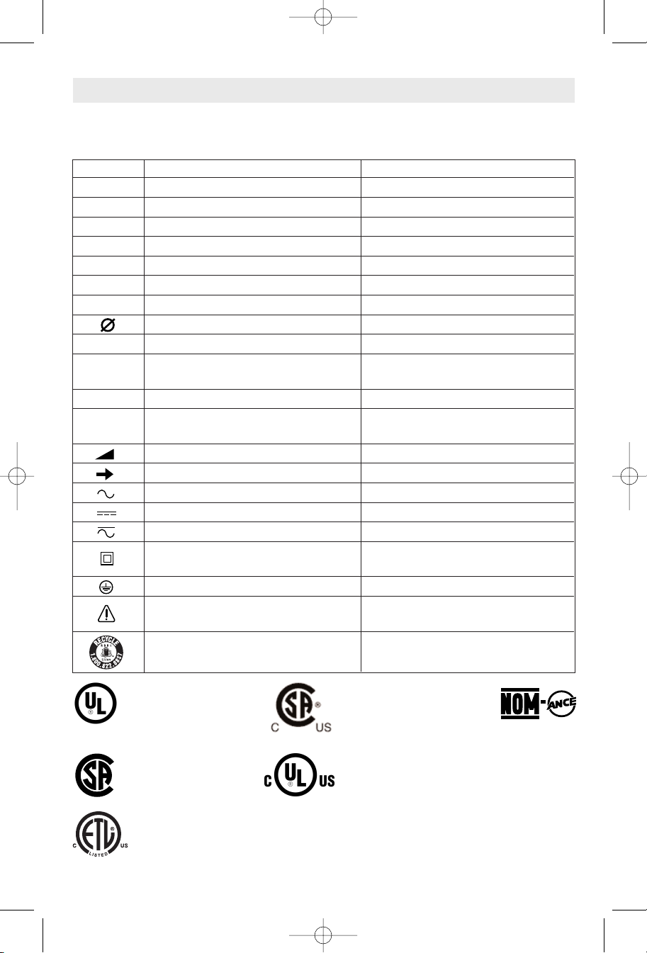
IMPORTANT: Some of the following symbols may be used on your tool. Please study them
and learn their meaning. Proper interpretation of these symbols will allow you to operate the
tool better and safer.
Symbol Name Designation/Explanation
V Volts Voltage (potential)
A Amperes Current
Hz Hertz Frequency (cycles per second)
W Watt Power
kg Kilograms Weight
min Minutes Time
s Seconds Time
Diameter Size of drill bits, grinding wheels, etc.
n
0
No load speed Rotational speed, at no load
.../min Revolutions or reciprocation per minute Revolutions, strokes, surface speed,
orbits etc. per minute
0 Off position Zero speed, zero torque...
1, 2, 3, ... Selector settings Speed, torque or position settings.
I, II, III, Higher number means greater speed
Infinitely variable selector with off Speed is increasing from 0 setting
Arrow Action in the direction of arrow
Alternating current Type or a characteristic of current
Direct current Type or a characteristic of current
Alternating or direct current Type or a characteristic of current
Class II construction Designates Double Insulated
Construction tools.
Earthing terminal Grounding terminal
Warning symbol Alerts user to warning messages
Li-ion RBRC seal Designates Li-ion battery recycling
program
Symbols
0
This symbol designates
that this tool is listed by
Underwriters Laboratories.
This symbol designates
that this tool is listed by
the Canadian Standards
Association.
This symbol designates that
this tool is listed by the
Canadian Standards
Association, to United States
and Canadian Standards.
This symbol
designates
that
this tool
complies
to NOM
Mexican
Standards.
This symbol designates that
this tool is listed by
Underwriters Laboratories, to
United States and Canadian
Standards.
This symbol designates that this tool is listed by the Intertek Testing
Services, to United States and Canadian Standards.
BM 1609929J65 02-08 2/20/08 11:30 AM Page 5
-6-
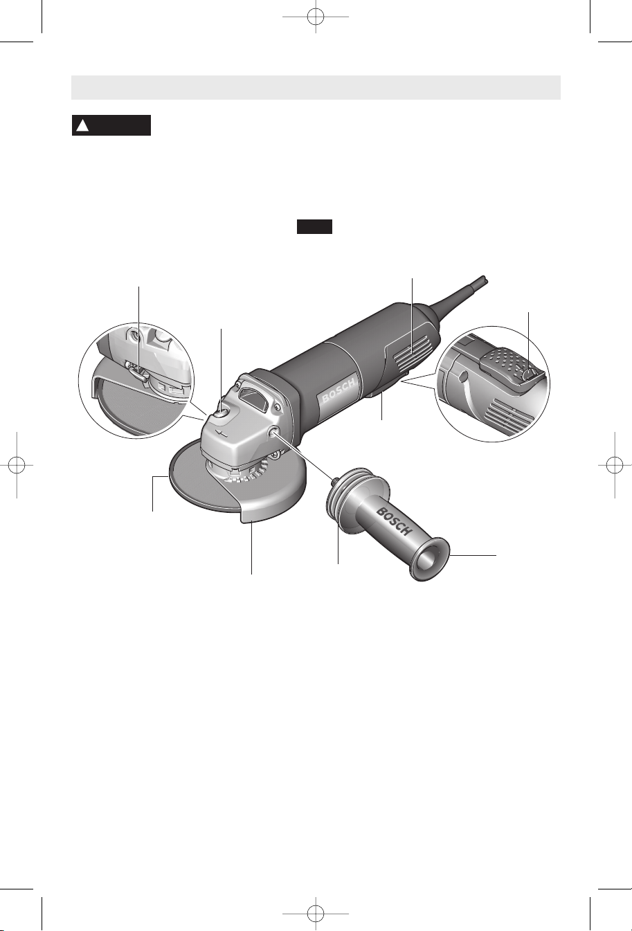
Functional Description and Specifications
Disconnect the plug from the power source before making any
a
ssembly, adjustments or changing accessories.
S
uch preventive safety
measures reduce the risk of starting the tool accidentally.
!
WARNING
NOTE: For tool specifications refer to the nameplate on your tool.
Angle Grinders
Model number 1810PS & 1810PSD 1811PS & 1811PSD 1812PSD
No load speed
n
0
11,000/
min
n
0
11,000/
min
n
0
11,000/
min
Max. wheel diameter 4 1/2" (115 mm) 5" (125 mm) 6" (150 mm)
Spindle thread 5/8"-11 UNC 5/8"-11 UNC 5/8"-11 UNC
Max. wire wheel 4" Dia. 4" Dia. 4" Dia.
Max. wire cup brush
3" Dia.
3" Dia. 3" Dia.
Max. sanding disc
4 1/2" Dia.
5" Dia.
6" Dia.
"LOCK-OFF"
SWITCH
RELEASE
LEVER
PADDLE
SWITCH
GUARD
RELEASE / ADJUSTMENT
BUTTON
VENTILATION
OPENINGS
GRINDING
WHEEL
WHEEL
GUARD
SIDE
HANDLE
VIBRATION
CONTROL
SIDE HANDLE
SPINDLE LOCK
FIG. 1
BM 1609929J65 02-08 2/20/08 11:30 AM Page 6
W
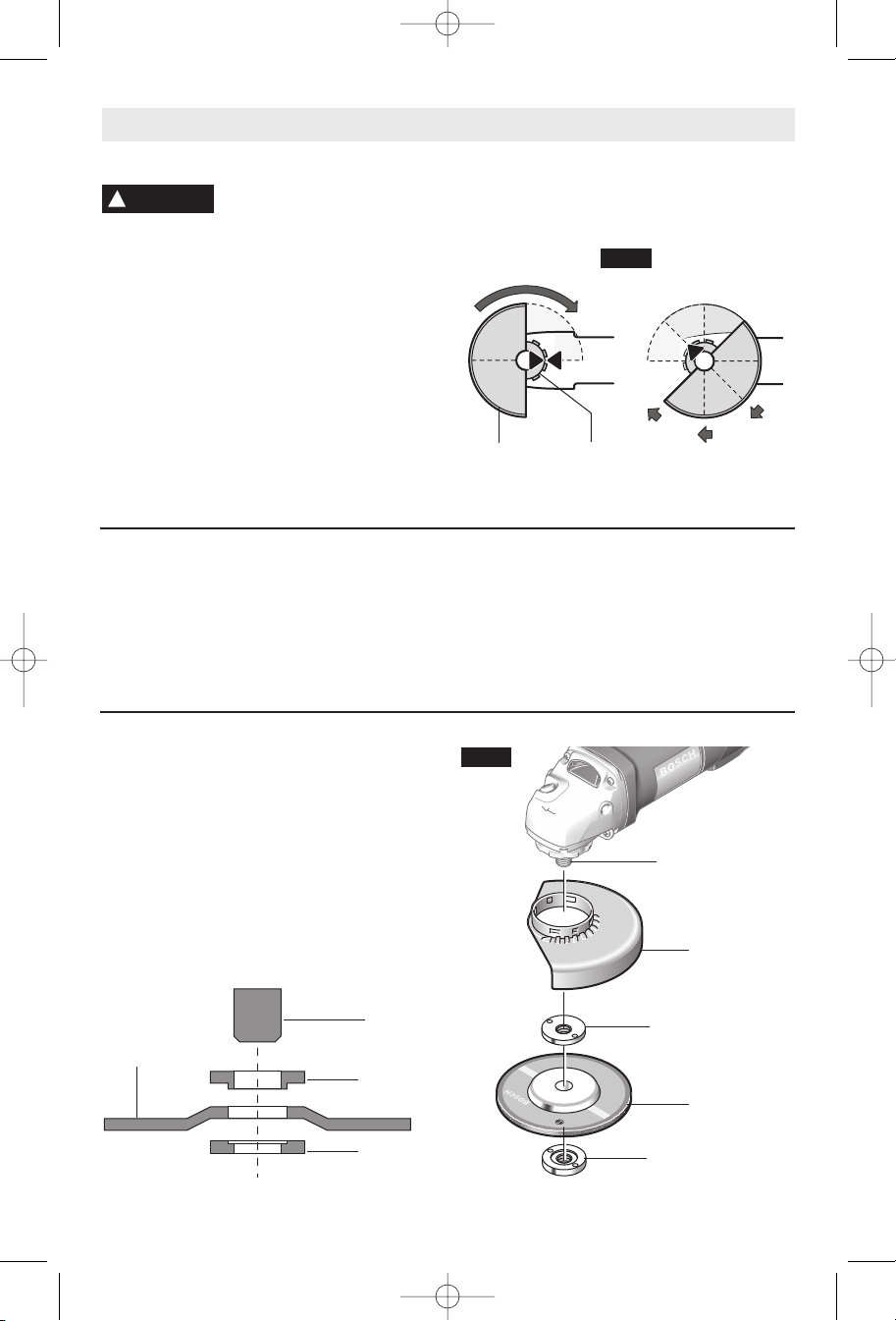
HEEL GUARD INSTALLATION
Wheel guard must be
attached when using disc
grinding wheels. Always keep wheel guard
between you and your work while grinding.
The position of the guard can be adjusted to
accommodate the operation being performed.
To attach wheel guard DISCONNECT tool
from power source.
Position wheel guard on spindle neck so that
the arrow on guard lines up with the arrow on
the spindle neck. Rotate wheel guard
clockwise 90º until it clicks in place (Fig. 2).
TO ADJUST GUARD: depress guard release
button (Fig. 1), rotate guard to desired position,
release button and let it click in place.
T
O REMOVE GUARD: Depress release button,
rotate guard until arrow on guard lines up with
arrow on spindle neck, and remove guard from
spindle neck.
Assembly
-7-
LOCK NUT AND BACKING FLANGE
Your tool is equipped with a threaded spindle
for mounting accessories. Always use the
supplied lock nut (and backing flange) that
has same thread size as spindle.
SIDE HANDLE
The side handle used to guide and balance the
tool can be threaded into the front housing on
either side of the tool, depending on personal
preference and comfort. Use the side handle
for safe control and ease of operation.
!
WARNING
Disc Grinding Wheel Assembly
(Models 1810PD, 1810PSD, 1811PS &
1811PSD only)
Disconnect tool from power source. Be sure
that wheel guard is in place for grinding.
Place BACKING FLANGE and GRINDING
WHEEL on the spindle. Thread on the lock
nut and tighten nut using the supplied lock
nut wrench, while holding the spindle lock in
(Fig. 3).
TO REMOVE: Reverse procedure.
LOCK NUT
TYPE 27
GRINDING
WHEEL
BACKING
FLANGE
SPINDLE
WHEEL
GUARD
SPINDLE
NECK
FIG. 2
GRINDING
WHEEL
LOCK NUT
SPINDLE
WHEEL
GUARD
BACKING
FLANGE
FIG. 3
BM 1609929J65 02-08 2/20/08 11:30 AM Page 7
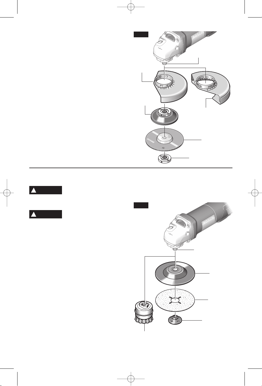
Disc Grinding Wheel Assembly
(Model 1812PSD only)
Disconnect tool from power source. Be sure
that wheel guard is in place for grinding.
When using spin-on grinding wheels, thread
directly onto the spindle.
When using mounting wheels, thread
BACKING FLANGE onto spindle, then place
GRINDING WHEEL on the spindle. Thread
on the lock nut and tighten nut using a lock
nut wrench provided with adapter kit, while
holding the spindle lock in (Fig. 4).
TO REMOVE: Reverse procedure.
-8-
Sanding Accessories Assembly
BACKING PAD
Before attaching a backing
pad be sure its maximum
safe operating speed is not exceeded by the
nameplate speed of the tool.
Wheel guard may not be
used for most sanding
operations. Always reinstall wheel guard
when converting back to grinding operations.
TO INSTALL BACKING PAD AND
SANDING DISC
Disconnect tool from power source. Set the
tool on its top side (spindle up). Place the
rubber backing pad onto the spindle shaft.
Center the sanding disc on top of the backing
pad. Insert the lock nut through the disc and
thread onto the spindle as far as you can with
your fingers. Press in the spindle lock, then
tighten the backing pad securely with lock nut
wrench (Fig. 5).
TO REMOVE BACKING PAD AND
SANDING DISC
Disconnect tool from power source. Using
the lock nut wrench unscrew the nut from the
spindle, while holding spindle lock in.
WIRE BRUSH ASSEMBLY
Before assembling wire brush to this tool,
disconnect from the power source. Wire
brushes are equipped with their own
threaded hub, simply thread on to spindle. Be
sure to seat against shoulder before turning
tool “ON”.
!
WARNING
SANDING
DISC
BACKING
PAD
LOCK NUT
WIRE
BRUSH
SPINDLE
FIG. 5
GRINDING
WHEEL
LOCK NUT
SPINDLE
TYPE 27
WHEEL
GUARD
BACKING
FLANGE
FIG. 4
TYPE 1
WHEEL GUARD
(Included with model
1812PSD only)
!
WARNING
BM 1609929J65 02-08 2/20/08 11:30 AM Page 8
-9-
Hold the tool with both hands
while starting the tool, since
torque from the motor can cause the tool to twist.
Start the tool before applying to work and let
the tool come to full speed before contacting
the workpiece. Lift the tool from the work
before releasing the switch. DO NOT turn the
switch “ON” and “OFF” while the tool is under
load; this will greatly decrease the switch life.
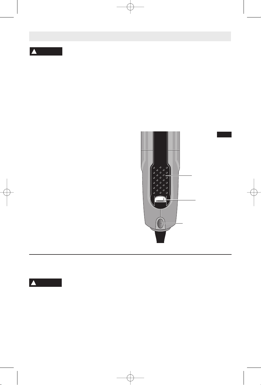
PADDLE SWITCH WITH
"LOCK-OFF"FEATURE
(Models 1810PSD, 1811PSD & 1812PSD
only)
The Paddle switch enables the operator to
control the switch functions of "Lock-OFF",
and "ON/OFF".
TO UNLOCK SWITCH AND TURN TOOL
"ON": Push "Lock-OFF" switch release lever
backward to unlock paddle switch, then
squeeze paddle switch (Fig. 6).
TO SWITCH TOOL "OFF": Release pressure
on paddle lever. The switch is spring loaded
and will return to "OFF" position automatically.
PADDLE SWITCH WITH "LOCK-OFF" AND
"LOCK-ON" FEATURE
(Models 1810PS & 1811PS only)
The Paddle switch enables the operator to
control the switch functions of "Lock-OFF",
"ON/OFF" and "Lock-ON".
TO UNLOCK SWITCH AND TURN TOOL
"ON": Push switch release lever backward to
unlock ON/OFF switch, then squeeze paddle
switch (Fig. 6).
TO SWITCH TOOL "OFF": Release pressure
on paddle lever. The switch is spring loaded
and will return to "OFF" position automatically.
"LOCK-ON" BUTTON
(Models 1810PS & 1811PS only)
The "Lock-ON" feature, incorporated into the
paddle switch, is a convenience for long
operations.
TO LOCK SWITCH "ON": After paddle switch
has been activated push "Lock-ON" button at
rear of tool completely in and release paddle
switch (Fig. 6).
TO SWITCH TOOL "OFF": Squeeze and
release paddle switch.
!
WARNING
Operating Instructions
SELECTING GRINDING WHEELS
Before using a grinding
wheel, be certain that its
maximum safe operating speed is not
exceeded by the nameplate speed of the
grinder. Do not exceed the recommended
wheel diameter.
DISC GRINDING WHEELS
Grinding wheels should be carefully selected in
order to use the grinder most efficiently.
Wheels vary in type of abrasive, bond,
hardness, grit size and structure. The correct
type of wheel to use is determined by the job.
Use disc grinding wheels for fast grinding of
structural steel, heavy weld beads, steel
casting, stainless steel and other ferrous
metals.
GRINDING TIPS
Efficient grinding is achieved by controlling the
pressure and keeping the angle between
wheel and workpiece at 10° to 15°. If the wheel
is flat, the tool is difficult to control. If the angle
is too steep, the pressure is concentrated on a
small area causing burning to the work
surface.
"LOCK-ON" BUTTON
(Models 1810PS &
1811PS only)
"LOCK-OFF"
SWITCH
RELEASE LEVER
PADDLE
SWITCH
FIG. 6
Grinding Operations
!
WARNING
BM 1609929J65 02-08 2/20/08 11:30 AM Page 9
SANDING TIPS
For best results, tilt the Disc Sander at a 10°
to 15° angle while sanding so that only about
1" of the surface around the edge of the disc
contacts the work.
If the disc (accessory) is held
flat or the back edge of the
disc comes in contact with the work, a violent
thrust to the side may result.
If sander is tilted too much, sanding action will
be too great and a rough cut surface or
gouging and snagging will result.
Guide the Disc Sander with crosswise strokes.
Be careful not to hold the sander in one spot
too long. Do not use a circular motion, as this
makes swirl marks. Test before use on scrap
stock.
Do not force or apply pressure when sanding.
Use only the weight of the tool for pressure.
Excess pressure actually slows the tool down.
If faster stock removal is desired, change to a
coarser grit disc.
Remove gummy paint from metal with an
“open coat” disc. Sand until sparks start to
appear, then stop and change to a “closed
coat” disc to remove any remaining paint.
SANDING WOOD
When sanding wood the direction of the disc
motion at the contact point should parallel the
grain as much as possible. The rapid cut of
discs and the swirl type scratch pattern they
occasionally create generally prohibit their use
for producing the final finish.
Scratches and circular marks are usually the
result of using too coarse a grit. When
changing to a finer grit, move across the sand-
ing lines that were made by a previous
coarser disc.
SANDING METAL
When sanding automobiles or appliances,
wipe the metal clean with a non-flammable
solvent or commercial cleaner to remove all
wax and grease. By doing this first, the
sanding discs will sand better and last longer.
For heavy duty work, use a coarse grit disc
first. Follow-up with a medium grit to remove
scratches. To produce smooth finish, use fine
grit disc.
!
WARNING
Sanding Operations
SELECTING SANDING DISC
Sanding discs are made of extremely hard
and sharp aluminum oxide grits, phenol-resin
bonded to a sturdy fiber backing for fast
heavy-duty service and long life. The discs
vary as to size and spacing of the abrasive
grits. OPEN COAT (type H) — used for soft
materials and on paint or varnish. CLOSED
COAT (type K) —used for metal, hardwood,
stone, marble and other materials.
Sanding discs range in grit from 16 (very
coarse) to 180 (very fine). To obtain best
results, select sanding discs carefully. Many
jobs require the use of several grit sizes and
at times both “open coat and closed coat”
discs are required to get the job done faster.
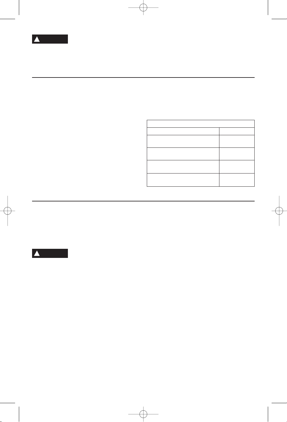
See chart for application examples.
Operation: Refinishing painted wood or metal surfaces.
REMARKS G
RIT
To remove paint and to smooth Coarse
surface irregularities. 16-24-30
To smooth Medium
the rough sanding. 36-50-80
To remove scratches left by Fine
previous discs. 100-120
To smooth surfaces for painting, Very Fine
polishing or waxing. 150-180
-10-
Excessive or sudden pres-
sure on the wheel will slow
grinding action and put dangerous stresses on
the wheel.
When grinding with a new wheel be certain to
grind while pulling tool backwards until wheel
becomes rounded on its edge. New wheels
have sharp corners which tend to “bite” or cut
into workpiece when pushing forward.
!
WARNING
BM 1609929J65 02-08 2/20/08 11:30 AM Page 10
Wire brushes are intended to “clean” structural
steel, castings, sheet metal, stone and
concrete. They are used to remove rust, scale
and paint.
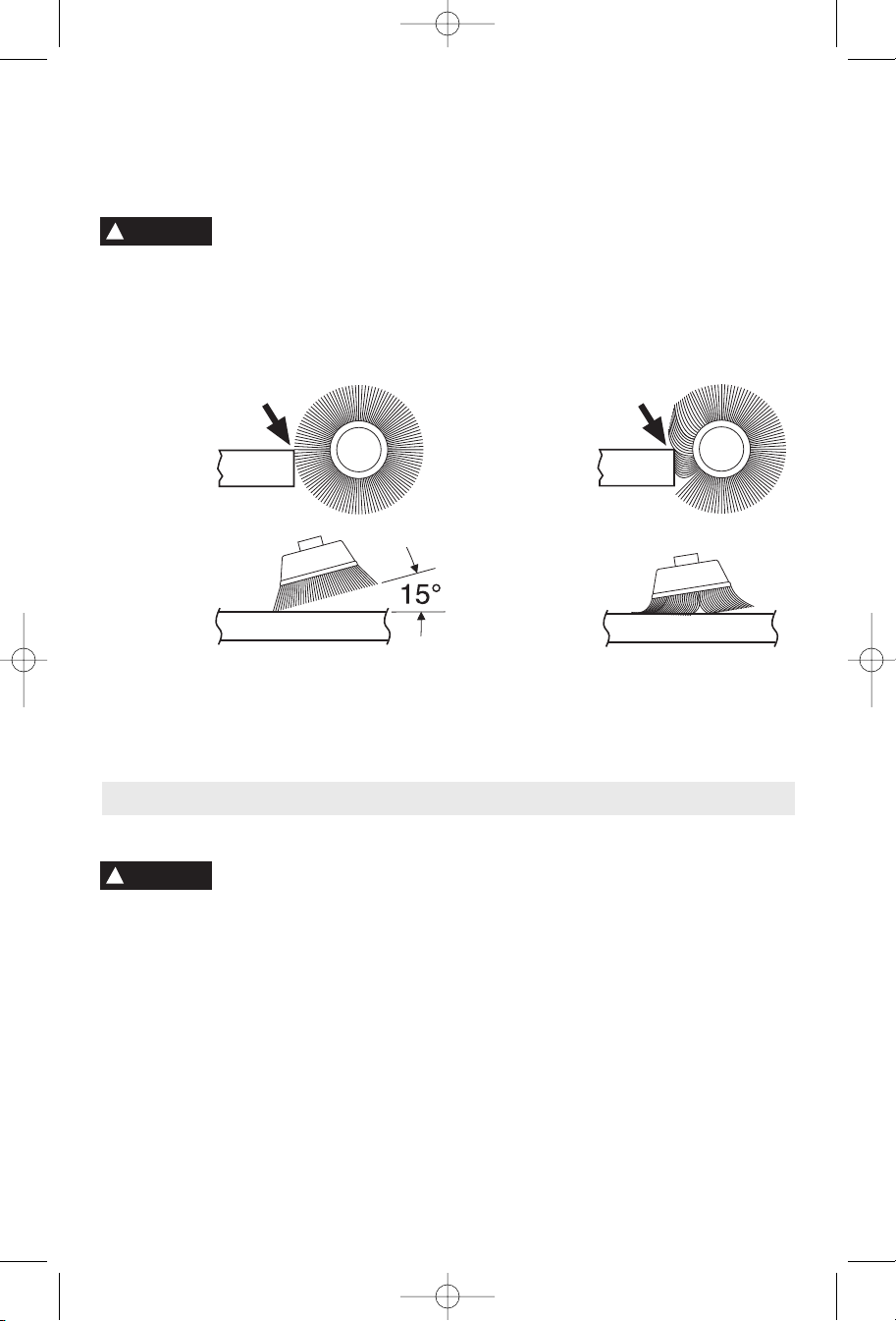
Avoid bouncing and snagging
the wire brush, especially
when working corners, sharp edges etc. This
can cause loss of control and kick-back.
BRUSHING PRESSURE
1. Remember, the tips of a wire brush do the
work. Operate the brush with the lightest
pressure so only the tips of the wire come in
contact with the work.
2. If heavier pressures are used, the wires
will be overstressed, resulting in a wiping
action; and if this is continued, the life of the
brush will be shortened due to wire fatigue.
3. Apply the brush to the work in such a way
that as much of the brush face as possible is
in full contact with the work. Applying the side
or edge of the brush to the work will result in
wire breakage and shortened brush life.
-11-
Service
Preventive maintenance
performed by unauth-
orized personnel may result in misplacing
of internal wires and components which
could cause serious hazard.
We
recommend that all tool service be performed
by a Bosch Factory Service Center or Autho
-
rized Bosch Service Station.
TOOL LUBRICATION
Your Bosch tool has been properly lubricated
and is ready to use. It is recommended that
tools with gears be regreased with a special
gear lubricant at every brush change.
CARBON BRUSHES
The brushes and commutator in your tool
have been engineered for many hours of
dependable service. To maintain peak
efficiency of the motor, we recommend every
two to six months the brushes be examined.
Only genuine Bosch replacement brushes
specially designed for your tool should be
used.
BEARINGS
After about 300-400 hours of operation, or at
every second brush change, the bearings
should be replaced at Bosch Factory Service
Center or Authorized Bosch Service Station.
Bearings which become noisy (due to heavy
load or very abrasive material cutting) should
be replaced at once to avoid overheating or
motor failure.
!
WARNING
Wire Brush Operations
CORRECT:
Wire tips doing
the work.
INCORRECT:
Excessive
pressure can
cause wire
breakage.
Maintenance
!
WARNING
BM 1609929J65 02-08 2/20/08 11:30 AM Page 11
 Loading...