


DRZ120
6-Zone Music & Paging System
© 2016 Bogen Communications, Inc. All rights reserved.
Specifications subject to change without notice. 54-2233-01B 1606
NOTICE: Every effort was made to ensure that the information in this guide was complete and accurate at the time of printing. However, information is subject to change.
WARNING: To reduce the risk of Fire or Electric Shock, Do Not Expose this apparatus to rain or moisture. The apparatus shall not be exposed to dripping or splashing and no objects filled with liquids, such as vases shall be placed on the apparatus.
WARNING: Only connect unit to AC mains outlet providing protective earthing connection.
NOTE: Mains plug is used as disconnect device from the mains and shall remain readily accessible and operable.
CAUTION: These servicing instructions are for use by qualified service personnel only. To reduce the risk of electric shock, do not perform any servicing other than that contained in the operating instructions unless you are qualified to do so.
CAUTION: DO NOT INSTALL OR PLACE THIS UNIT IN A BOOKCASE, BUILT-IN CABINET, OR IN ANOTHER CONFINED SPACE. ENSURE THE UNIT IS WELL VENTILATED. TO PREVENT THE RISK OF SHOCK OR FIRE HAZARD DUE TO OVERHEATING, ENSURE THAT CURTAINS AND ANY OTHER MATERIALS DO NOT OBSTRUCT THE VENTILATION VENTS.
Always follow these basic safety precautions when installing and using the unit:
IMPORTANT SAFETY INSTRUCTIONS
1.Read these instructions.
2.Keep these instructions.
3.Heed all warnings.
4.Follow all instructions.
5.Do not use this apparatus near water.
6.Clean unit with dry cloth.
7.Do not block any ventilation openings. Install in accordance with the manufacturer's instructions.
8.Do not install near any heat sources such as radiators, heat registers, stoves, or other apparatus (including amplifiers) that produce heat.
9.Do not defeat the safety purpose of the polarized or groundingtype plug. A polarized plug has two blades with one wider than the other. A grounding-type plug has two blades and a third grounding prong.The wide blade, or the third prong, are provided for your safety. If the provided plug does not fit into your outlet, consult an electrician for replacement of the obsolete outlet.
10.Protect the power cord from being walked on or pinched particularly at plugs, convenience receptacles, and the point where they exit from the apparatus.
11.Only use attachments/accessories specified by manufacturer.
12.Unplug this apparatus during lightning storms or when not used for long periods of time.
13.Refer all servicing to qualified service personnel. Servicing is required when the apparatus has been damaged in any way, such as power-supply cord or plug is damaged, liquid has been spilled or objects have fallen into the apparatus, the apparatus has been exposed to rain or moisture, does not operate normally, or has been dropped.
CAUTION
Changes or modifications not expressly approved by the party responsible for compliance could void the user's authority to operate the equipment.
This equipment has been tested and found to comply with the limits for a Class B digital device, pursuant to Part 15 of the FCC Rules. These limits are designed to provide reasonable protection against harmful interference in a residential installation. This equipment generates, uses, and can radiate radio frequency energy and, if not installed and used in accordance with the instructions, may cause harmful interference to radio communications. However, there is no guarantee that interference will not occur in a particular installation. If this equipment does cause harmful interference to radio or television reception, which can be determined by turning the equipment off and on, the user is encouraged to try to correct the interference by one or more of the following measures:
—Reorient or relocate the receiving antenna.
—Increase the separation between the equipment and receiver.
—Connect the equipment into an outlet on a circuit different from that to which the receiver is connected.
—Consult the dealer or an experienced radio/TV technician for help.
CAUTION
RISK OF ELECTRIC SHOCK
DO NOT OPEN
CAUTION: TO PREVENT THE RISK OF ELECTRIC SHOCK, DO NOT REMOVE ANY FRONT/ BACK COVERS OR PANELS. NO USERSERVICEABLE PARTS INSIDE.
REFER SERVICING TO QUALIFIED PERSONNEL.
The lightning flash with arrowhead symbol, within an equilateral triangle, is intended to alert the user to the presence of uninsulated "dangerous voltage" within the product's enclosure that may be of sufficient magnitude to constitute a risk of electric shock to persons.
The exclamation point that is within an equilateral triangle is intended to alert the user to the presence of important operating and maintenance (servicing) instructions.
Contents
DRZ120 6-Zone Music & Paging System
|
Page |
DRZ120 FRONT PANEL ........................................................................................................................ |
2 |
DRZ120 REAR PANEL .......................................................................................................................... |
3 |
INFRARED REMOTE CONTROLLER........................................…………………………………………...4 |
|
INSTALLATION ..........................................…………………………………………………………………...5 |
|
CONNECTIONS..........................................…………………………………………………………………...6 |
|
OPERATION ..........................................…………………………………………………….………………...7 |
|
TECHNICAL SPECIFICATIONS..................…………………………………………………………………..8 |
|
LIMITED WARRANTY; EXCLUSION OF CERTAIN DAMAGES .......................................................... |
9 |

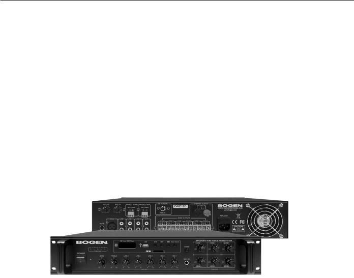
DRZ120 Front Panel
2 |
4 |
6 |
8 |
10 |
|
Output Level |
|
||
POWER |
|
|
|
|
|
|
|
BASS |
|
|
|
|
|
0 |
|
|
|
-10 |
+10 |
|
|
FM Tuner / MP3 Player |
|
|
USB |
|
|
|
Music Source |
|
DRZ120 6-ZONE MUSIC & PAGING SYSTEM |
|
||||||
|
|
|
|
|
|
|
|
|
|
|
|
|
|
|
|
|||
|
|
|
|
|
|
|
|
|
|
|
|
|
3 |
|
3 |
|
3 |
|
|
|
|
|
|
|
|
|
|
|
|
|
CHIME |
1 |
5 |
1 |
5 |
1 |
5 |
|
|
|
|
|
|
|
|
|
|
|
|
|
OFF |
|
OFF |
|
OFF |
|
TREBLE |
|
LINE 3 |
|
LINE 2 |
|
LINE 1 |
|
MIC 2 |
|
MIC 1 |
|
3 |
|
3 |
|
3 |
|
|
|
0 |
|
0 |
|
0 |
|
0 |
|
0 |
|
0 |
MIC1 IN |
|
|
|
|||
|
|
|
|
|
|
|
|
|
|
|
|
1 |
5 |
1 |
5 |
1 |
5 |
|
|
|
|
|
|
|
|
|
|
|
|
|
|
||||||
|
|
|
|
|
|
|
|
|
|
|
|
|
OFF |
|
OFF |
|
OFF |
|
-10 |
+10 |
0 |
10 |
0 |
10 |
0 |
10 |
0 |
10 |
0 |
10 |
|
|
|
|
|
|
|
|
|
|
|
|
|
Input Level |
|
|
|
|
|
|
|
|
Output Level |
|
|
|
1.Master POWER Switch
Turns Power to DRZ120 unit ON or OFF.
2.Power ON Indicator
Indicates when Power is on.
3. BASS Tone Control
Controls the amount of cut or boost of Bass frequencies below 100 Hz.
4. TREBLE Tone Control
Controls the amount of cut or boost of Treble frequencies above 10 kHz.
5. LINE Input Level Controls
Controls level of each Line input.
6. MIC1 and MIC2 Input Level Controls
Controls level of MIC1 and MIC2 inputs.
7. MIC1 IN Input
Accepts 1/4” TRS-type microphone input connector.
8. Zone Output Level Controls
Individual control levels for the output of each of six zones (ZONE 1 thru ZONE 6).
9. Zone Level LED Indicators
Indicates zone output level visually by LED intensity. The brighter the LED, the louder the zone level.
10.Chime
When the CHIME button is pushed, a short melodic series of four ascending bell-like tones is generated to all outputs. These tones are generated at a high output level, so care should be taken when using CHIME with high zone output settings.
11. SD Card Slot
Slot for SD Card connection for MP3 files.
12.MP3/TUNER Button
Select MP3 or FM Tuner as input source. Current selection is displayed on Status Display (#17).
13-15. FM Tuner/MP3 Multi-Operation Buttons
FM Tuner Mode: Advances to the next station preset.
MP3 Mode: Advances to next track.
FM Tuner Mode: Selects the previous station preset.
MP3 Mode: Selects previous track.
FM Tuner Mode: Scans preset FM bands.
MP3 Mode: Play/Pause selected track.
16.USB Port
Port for USB drive connection for MP3 files.
17.FM Tuner/MP3 Player Status Display
Indicates which mode source is active (RAD, USB, SD and AUX).
18.Output Level Indicator
Five-segment LED output level indicator. Maximum recommended operating output level is 8.
Note: When all five units of the LED output level indicator remain lit, it indicates that the sound is distorted and may result in undesired audio quality. To resolve this issue, decrease one or more of the Line/MIC Input levels until at least one LED does not light. If the output level is allowed to 'max. out' (i.e., output level of 10) for any extended period, then the unit will enter 'protection mode' - opening a output protection relay and sounding an alarm. To reset the alarm, the Power Switch (#1) must be turned OFF and then back ON.
2
 Loading...