


Zone Controller with Universal Telephone Interface UTI312 Model
Installation and Use Manual
© 2004 Bogen Communications, Inc. All rights reserved.
Specifications subject to change without notice. 54-2120-01A 0411
© 2004 Bogen Communications, Inc. All Rights Reserved.
UL Approved Notice
Every effort was made to ensure that the information in this manual was complete and accurate at the time of printing. However, information is subject to change.
FCC Statement (Part 15) - Radio Frequency Interference
The Universal Telephone Interface generates and uses radio frequency energy and if not installed and used in strict accordance with the manufacturer's instructions, may cause interference to radio and television reception. Testing is being conducted for compliance with the limits for a Class B device in accordance with the specifications in Part 15 of the FCC Rules and Canadian D.O.C. regulations.This testing is designed to provide reasonable protection against such interference. However, there is no guarantee that interference will not occur in a particular installation. If this equipment does cause interference to radio or television reception, which can be determined by turning the UTI312 unit off and on, the user is encouraged to try to correct the interference by one or more of the following measures:
-Reorient the radio or TV receiving antenna.
-Relocate the UTI312 unit with respect to the radio or TV receiver or vice-versa.
-Plug the UTI312 unit into a different outlet so that it and the radio or TV receiver are on different branch circuits.
If necessary, the user should consult the dealer or an experienced radio/television technician for additional suggestions.The user may find the following booklet, "How To Identify and Resolve Radio-TV Interference Problems," helpful. This booklet was prepared by the Federal Communications Commission (FCC) and is available from the U.S. Government Printing Office,Washington, DC 20402. Stock order No. 004-000-00345-4.
Federal Communications Commission (FCC) Statement (Part 68)
This equipment is component registered with the Federal Communications Commission (FCC) in accordance with Part 68 of its rules. In compliance with the rules, be advised of the following:
Registered equipment may not be used with Coin Telephone Lines. Equipment may be used with Party Lines in areas where state tariffs permit such connections and when equipment is adaptable for such service.
This equipment is registered as follows: Registration Number - CD2PA13BUTI312 Ringer Equivalence - 1.4B
If trouble is experienced, the equipment should be disconnected from the interface to determine if this equipment, or the telephone line is the trouble source. If the equipment is determined to be malfunctioning, it should not be reconnected until repairs are effected.
Repairs to this equipment, other than routine repairs, can be made only by the manufacturer or its authorized agents.
If the equipment causes harm to the telephone network, the local telephone company may temporarily discontinue your service and, if possible, notify you in advance. If advance notice is not practical, you will be notified as soon as possible.You will be given the opportunity to correct the problem and informed of your right to file a complaint with the FCC.
The local telephone company may make changes in its facilities, operations, or procedures that could affect the proper functioning of your equipment. If they do, you will be given adequate notice in writing to allow you an opportunity to maintain uninterrupted telephone service.
Important Safety Information
Always follow these basic safety precautions when installing and using the system:
1. Read and understand all instructions.
2.Follow all warnings and instructions marked on the product.
3.DO NOT block or cover the ventilation slots and openings. They prevent the product from overheating. DO NOT place the product in a separate enclosure or cabinet, unless proper ventilation is provided.
4.Never spill liquid on the product or drop objects into the ventilation slots and openings. Doing so may result in serious damage to the components.
5.Repair or service must be performed by a factory authorized repair facility.
6.The product is provided with a UL-CSA approved, 3-wire ground type plug. This is a safety feature. DO NOT defeat the safety purpose of the grounding type plug. DO NOT staple or otherwise attach the AC power supply cord to building surfaces.
7.DO NOT use the product near water or in a wet or damp place (such as a wet basement).
8.DO NOT use extension cords. The product must be installed within 6 feet of a grounded outlet receptacle.
9.DO NOT install telephone wiring during a lightning storm.
10. DO NOT install telephone jacks in a wet location unless the jack is specifically designed for wet locations.
11. Never touch uninsulated wires or terminals, unless the line has been disconnected at the paging or controller interface.
12. Use caution when installing or modifying paging or control lines.
Contents |
|
Introduction ...................................................... |
4 |
Voice Channel .............................................................. |
4 |
Background Music ........................................................ |
4 |
Signaling Tones .............................................................. |
4 |
Other Features ............................................................ |
4 |
Package Contents ........................................................ |
4 |
Panel Descriptions............................................ |
5 |
Installation ........................................................ |
6 |
Mounting ........................................................................ |
6 |
ZX3 Module Installation & Jumper Selections ...... |
6 |
Telephone Interface |
|
Wiring Connections & Setup.......................... |
7-10 |
Telephone System Connections .............................. |
7 |
PBX Analog Station Port ............................................ |
7 |
PBX Loop Start Trunk Port ...................................... |
8 |
PBX Ground Start Trunk Port .................................. |
8 |
Trunk Disconnect ........................................................ |
9 |
PBX Page Port Contact.............................................. |
9 |
PBX Page Port VOX .................................................... |
9 |
Override Input.............................................................. |
10 |
90V Night Ring Input .................................................. |
10 |
Other Connections .......................................... |
11 |
Night Ringer Contact.................................................. |
11 |
Tone Trigger Inputs 1 & 2 .......................................... |
11 |
Background Music Inputs .......................................... |
11 |
UTI312 AUX Contacts .............................................. |
11 |
ZX3 Module Connections................................ |
12 |
ZX3 Module Paging Output Connections ............ |
12 |
ZX3 AUX Contacts .................................................... |
12 |
ZX3 Power Supply Output........................................ |
12 |
Controls ............................................................ |
13 |
Paging Level.................................................................... |
13 |
Music Level .................................................................... |
13 |
Tone Level...................................................................... |
13 |
Night Ring Level .......................................................... |
13 |
Limiter Threshold ........................................................ |
13 |
Features & Operation ...................................... |
14-17 |
Zones .............................................................................. |
14 |
Paging Zone Groups.................................................... |
14 |
All-Call Zone Group .................................................. |
14 |
Auto Select Zone Group .......................................... |
15 |
Override Zone Group & Tone.................................. |
15 |
Night Ring Zone Group & Tone .............................. |
15 |
Tone Trigger 1 & 2 Zone Groups & Tones ............ |
15 |
Code Call Zone Group & Tones .............................. |
16 |
AUX Relay Contact .................................................... |
16 |
Flexible Dialing.............................................................. |
16 |
Confirmation Tone ...................................................... |
16 |
Pre-Announce Tone .................................................... |
16 |
Dialing Time-out .......................................................... |
17 |
DTMF Block .................................................................. |
17 |
Trunk Disconnect ........................................................ |
17 |
Timers ............................................................................ |
17 |
Calling Party Controlled Disconnect ...................... |
17 |
Setup Tone...................................................................... |
17 |
Reset Default Values .................................................... |
17 |
Priority Levels .............................................................. |
17 |
System Programming ...................................... |
18-22 |
Paging Zone Groups .................................................... |
18 |
All-Call Zone Group .................................................. |
18 |
Auto Select Zone Group .......................................... |
18 |
Tone Zone Groups ...................................................... |
19 |
Code Calling.................................................................. |
19 |
DTMF Block .................................................................. |
19 |
Timers ............................................................................ |
19 |
AUX Relay Contact .................................................... |
20-21 |
Flexible Dialing.............................................................. |
22 |
Feature Codes & Defaults .............................. |
23-26 |
Specifications .................................................... |
27 |
Block Diagram, UTI312 .................................. |
28 |
Block Diagram, ZX3 ........................................ |
29 |
Limited Warranty ............................................ |
30 |
3

Introduction
The UTI312 Paging System is an expandable multi-zone paging and signaling system.The system provides the following features and functions:
Voice Channel
•Expandable to 12 zones
•Telephone interfaces:
-loop start trunk
-ground start trunk
-station access (analog ring-up)
-page port contact closure activation
-page port voice activation
•Override paging (using loop start trunk or page port contact closure activation) zone group
•Audio output with level control per zone can provide audio for 150 Bogen one-way self-amplified speakers; also compatible with 70V amp inputs
•Zone activity LEDs
•Zone contact closure
•Pre-Announce/Confirmation Tone
•Adjustable Automatic Level Control with threshold and active indicator
Background Music
•Two high-impedance transformer isolated BGM inputs
•Individual volume controls
•Background music source selectable per zone
•Stereo combining inputs
Signaling Tones
• |
Night Ringer (90V and contact closure activation) with zone group |
• |
Two Tone Triggers (tone and duration selectable, closure activated) with individual zone groups |
• |
Code Calling with zone group |
Other Features
•Flexible dialing plan for zone numbers
•2 to 5 digit dialing plans
•24 zone groups
•C-form contact set with programmable activation events
•Non-volatile memory for setup data
•Setup Tone to assist in volume setting, etc.
•Pluggable terminal strips
•Microcontroller-based operation
•DTMF setting of operating parameters
Package Contents
•(1) UTI312
•(1) Installation and Use Manual
•(1) ZX3 Module (installed)
4

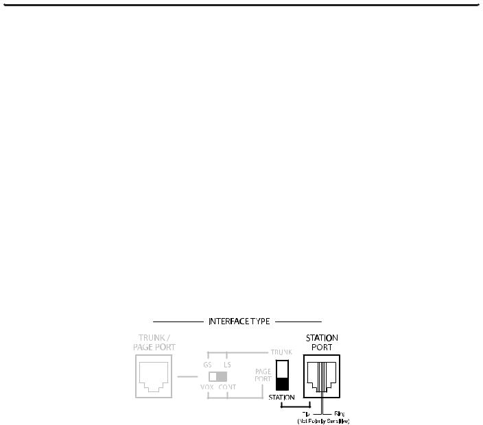
Panel Descriptions
UTI312 Front Panel with ZX3 Installed
UTI312 Callouts
1. Ground Start Terminal - Connection for PBX ground. Used only when the ground start interface is selected.
2.Earth Ground Terminal - Provides connection to the UTI312 Earth Ground. This terminal can be connected to the GND STRT terminal when using the ground start interface if the UTI312 and the PBX share the same Earth Ground.
3.AUX Contact Terminals - Provides connections for normally open and normally closed contact closures.The contact closure can be programmed to activate during paging, night ring, tone, override, or any combination (refer to System Programming).
4.Tone and Night Ring Terminals / Tone and Night Ring Level Controls - Terminals provide connections to night
ring and tone trigger inputs. Tone Level control sets the level of all tones produced by the system except for the Night Ring tone. Night Ring Level control sets level of Night Ring tone.
5.Program/Run Switch & LED - Switch to set unit to Program mode.The LED will light when unit is in Program mode.
6.Limiter Threshold / Limiter Active LED - Threshold control and indicator for output limiter function.
7.Music Level Control - Music Level control sets the background music level for music sources A and B.
8 Music Input Jacks - Stereo summing input for background music sources A and B. 9. Power Indicator - Illuminates when AC power has been applied to the unit.
10. Override - Highest priority input allows for loop start or page port with contact activation or open collector output.
11. Trunk/Page Port - Primary paging interface to telephone system when UTI312 is set to trunk or page port mode type interface.
12. Interface Type Slide Switches - Sets telephone interface type for the UTI312.
13. Station Port - Primary paging interface to telephone switch when UTI312 is set to station mode type interface. 14. Night Ring - Provides connection for 90V Night Ring.
ZX3 Callouts
15. ZX3 Module Zone Page Level Controls - Level controls adjust the level of the page output for each zone. Each zone has its own Level control.
16. ZX3 Module Zone Active LED - The LED for each zone will light when the zone is active.
17. ZX3 Module Zone Page Terminals - Provides audio signal for up to 150 self-amplified speakers. 18. ZX3 Module Zone Contact Terminals - N.O./N.C. contacts change state when zone is active.
19. ZX3 Plug-In Module - Provides 1 to 3 paging zones; add up to 3 additional ZX3 modules for up to 12 paging zones. 20. Module Bay - Module bay accepts up to four ZX3 modules, for a total of 12 zones of paging. One pre-installed.
21. Auxiliary 24V Terminals - Provides connections to the UTI312 1A, 24V DC power supply for powering self-amplified speakers.
5
Installation
Mounting
Wall Mounting
Mounting to a plywood backboard or studs:
1. On each side remove the four screws in the corners and use them to attach the mounting flanges so that the flanges are facing the rear of the unit.
2.Hold the unit level against the surface to which it will be mounted.
3.Using the keyholes, mark on the mounting surface where the mounting screws (not included) should be positioned.
4.Set the unit aside and install the screws leaving about 1/4" of the screws sticking out of the surface.
5.Slip the unit over the screws through the keyholes and let the unit rest on the screws.Tighten screws snugly.
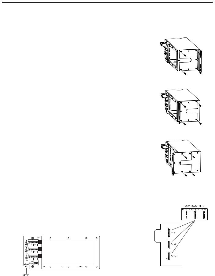
Rack Mounting, Flush
Mounting flush to a rack:
1. On each side remove the four screws in the corners and use them to attach the mounting flanges so that the flanges are facing the front of the unit.
2.Attach unit to rack with 4 rack screws (not supplied). Do not use keyholes for mounting to a rack.
Rack Mounting, Recessed for Wire Access
Recessed in a rack to allow for top or bottom wire entry:
1. On each side remove the four screws in the corners and use them to mount the mounting flanges so that the flanges are protruded from the front of the unit.This recess allows enough space for wire access from top or bottom.
2.Attach unit to rack with 4 rack screws (not supplied). Do not use keyholes for mounting to a rack.
ZX3 Module Installation & Jumper Selections
The UTI312 module bay can accommodate up to four ZX3 modules. Each ZX3 module has 3 zone outputs giving the UTI312 a capacity of up to 12 paging zones.
Each module slot is marked on the lower left hand corner indicating which zones correspond with each slot.
To install, first select each zone’s Music Bus A or B or (no music) using the jumpers, then slide the ZX3 module into the card guides and push the module all the way home. Secure with mounting screws.
Wall Mounting
Rack Mounting, Flush
Rack Mounting,Wire Access
ZX3 BGM Jumper Selections
6
Telephone Interface
Wiring Connections & Setup
Telephone System Connections
The UTI312 connects to virtually any telephone system: PBX station lines and CO lines, PBX loop start trunk ports, PBX ground start trunk ports, and page ports.
Interface installation consists of setting the slide switches and connecting with modular (RJ11) telephone plugs. Refer to the appropriate procedure in this section to connect the UTI312 to the telephone system.
Note: In all cases, make sure that power to the UTI312 is disconnected before performing the installation.
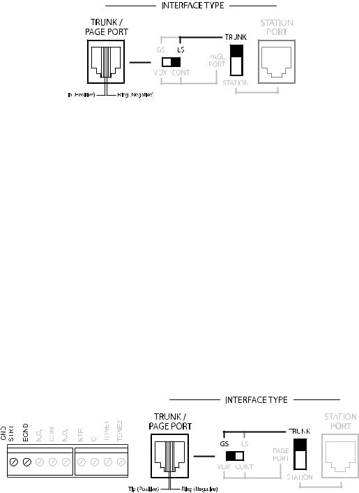
PBX Analog Station Port
In this configuration, the unit answers immediately upon detecting a ring. As soon as it answers, the default timer andVOX timer are started.The default timer determines the maximum length of any page.TheVOX timer repeatedly resets as long as audio is detected on the line. If no audio is detected within the VOX time period, then the page will end. If audio continues to be detected, then the default timer will control page length.
The unit will also immediately disconnect if a loss of loop current CPC (Calling Party Disconnect) is detected.
Make sure that the power is off and all connections are completed before proceeding. Move the interface slide switch on the UTI312 to STATION.The other interface slide switch is not used and can be in any position. Use a modular telephone cord (minimum 2-conductor) to connect the UTI312 Station Port RJ11 to the phone system. The center two conductors are Tip and Ring and are not polarity sensitive (see below). Set Default and VOX timers (see System Programming).The timers can be independently inhibited.
Note:The default time-out is factory set to 30 seconds, and the VOX time-out is set to 6 seconds. If both the default and VOX timers are inhibited, the only way to release the system from the station line is through the use of a Calling Party Control (CPC) pulse.
7
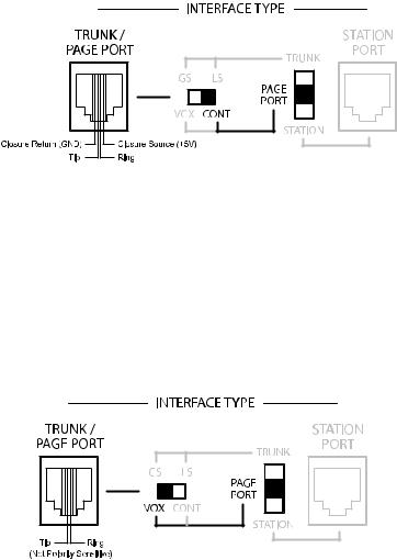
PBX Loop Start Trunk Port
In this configuration, the unit supplies a 24V talk battery and loop current detection.When the unit detects a loop resistance between Tip and Ring, it activates.When the loop opens, the page ends.The unit follows the status of the trunk port.
Before configuring the UTI312 for a loop start trunk port, make sure that the power is disconnected and all other connections are completed. Move the slide switches on the UTI312 to the positions shown below. Use a modular telephone cord to connect the unit to the phone system.
The center two conductors are Tip and Ring (24V DC) and have a specific polarity as shown in the figure below. If the polarity that the trunk requires is opposite, you can use a reversing modular cord to make the connection or reverse the connection through a modular block.The Trunk Disconnect feature is available in this mode (description on page 9).
PBX Ground Start Trunk Port
In this configuration, the unit supplies 24V talk battery, a contact in the Tip circuit, and loop current detector in the ring circuit. When the ground start trunk grounds Ring, the unit responds by closing the connection to Tip, which completes the access procedure.When the loop is opened, the page ends.The unit follows the status of the trunk.
Before proceeding, make sure that the power is disconnected and all other connections are completed. Move the slide switches on the UTI312 to the positions shown below. Use a modular telephone cord to connect the unit to the phone system. Connect the GND STRT terminal on the UTI312 to the PBX ground. This is typically the AC ground for the PBX system. If the PBX is using the same Earth Ground as the UTI312, the Earth Ground terminal can be shorted to the GND STRT terminal instead of running a ground wire from the PBX.
The center two conductors are Tip and Ring (24V DC) and have a specific polarity as shown in the figure below. If the polarity that the trunk requires is opposite, you can use a reversing modular cord to make the connection or reverse the connection through a modular block.The Trunk Disconnect feature is available in this mode (description on page 9).
IMPORTANT - When the GND STRT terminal is connected to Earth Ground, it is important that none of the UTI312 system ground terminals are connected to Earth Ground. These terminals may accidentally be connected to Earth Ground when external equipment, such as a CD player, tuner, announcement device, etc., is connected to the UTI312.The UTI312 ground points are: the closure return terminal for the Trunk/Page Port jack, the contact closure (GND) and the left-most Dry Audio input terminal of the Override jack, the C terminal for the Night Ring, and the Tone Trigger input.The background music input and page outputs are transformer-isolated and are unaffected by Earth Ground. If the UTI312 system ground is tied to Earth Ground, then the UTI312 talk battery voltage will be shorted to ground and the unit will not function properly. For location of UTI312 system ground terminals, refer to the UTI312 Block Diagram.
8
Trunk Disconnect
The UTI312 includes a Trunk Disconnect feature. The purpose of the Trunk Disconnect feature is to release the UTI312 from the trunk port in the event a user does not hang up the phone properly after making a page. If the UTI312 does not detect voice for the interface VOX time-out period, or if the interface default timer expires, the UTI312 will attempt to release from the trunk. When using the Trunk Disconnect feature, the PBX must have disconnect supervision available on the trunk port being used.The Trunk Disconnect feature is disabled by default. To set the VOX and default timers and enable the feature, refer to System Programming.
PBX Page Port Contact
In this configuration, the unit responds to a contact shorting the closure source to its return. When the short is removed, the page ends.Audio is provided to the system through a separate pair of dry audio input leads.
Make sure that the power is disconnected and all other connections are completed before proceeding. Move the slide switches on the UTI312 to the positions shown below. Use a modular telephone cord to connect the module to the phone system.
The center two conductors are used for dry audio (no DC voltage) and the connectors on either side are connected to the page port contact closure. The maximum resistance of the page port contact closure loop resistance is 1000 ohms. Open collector type outputs may also be used for controlling a page.The Trunk Disconnect feature is not available in this mode.
PBX Page Port VOX
In this configuration, the unit activates when audio on the page input is detected. Loss of audio allows theVOX timer to expire and ends the page.
Make sure that the power is disconnected and all other connections are completed before proceeding. Move the slide switches on the UTI312 to the positions shown below. Use a modular telephone cord to connect the module to the phone system.The center two conductors are used for dry audio and are not polarity sensitive.The Trunk Disconnect feature is not available in this mode.
Note:The default time-out is factory set to 30 seconds, and the VOX time-out is set to 6 seconds. If both the default and VOX timers are inhibited, there is no way to release the system from the page port VOX.
9

Override Input
The Override is a feature that lets the caller take priority over all other paging functions and make a page.
The center two conductors interface directly to a Loop Start Trunk or a dedicated phone.When the trunk becomes active, the UTI312 goes into Override mode. A contact closure and dry audio source can also be used for the Override Input. The two conductors flanking the talk battery conductors provide a dry audio gateway into the system override. Override is activated by shorting the outermost conductors.
Maximum contact closure resistance is 1000 ohms. Open collector type outputs for controlling a page may also be used.The Override feature includes a quad beep pre-announce tone that can be enabled or disabled. (The default is enabled.) Make sure that the power is disconnected and all other connections are completed before proceeding. Plug modular cord into OVERRIDE (RJ11) jack.
90V Night Ring Input
The 90V Night Ring Input connects to an analog station line from the PBX or directly to a central office phone line. The UTI312 will follow the incoming ring signal cadence with a simulated ring or chime tone to the Night Ring zone group.
Note: The Night Ring feature has priority just above background music.There is a 5-second delay after the night ring stops before background music is restored (to bridge inter-ring pause).
10
 Loading...