


BX8893
AutoStop™
Operator Manual &
Installation Instructions
Serial Number
AutoStop™ Hitch Connector
Alpha & Aladdin Tow Bars
(7500 lb) 2” Receiver
292-2214 Rev A |
Page 1 of 12 |
10/4/13 |

BX8893
AutoStop™
Operation Manual & Installation Instructions
Autostop™ uses the forward momentum of your towed vehicle to effect a smooth quick stop, reducing braking distances as much as 30 percent. When your RV slows down, the momentum of the towed vehicle pushes AutoStop™ into the hitch. Autostop™ retracts the cable, proportionally activating your car’s brakes. The more force applied to Autostop™, the tighter the cable - for even more supplemental braking power. The Autostop™ cable wraps around your car’s brake pedal arm and connects to the receiver hitch. You determine when the car’s brakes will activate by adjusting the preload compression of the power spring. Autostop™ does not invade the car’s or motorhome’s brake system in any way. The adjustable preload and power return is easily modified but still proportional in braking.
 CAUTION: The loaded vehicle weight must not exceed the weight of any of your towing accessories such as: the tow bar, safety cables, pins or the AutoStop™.
AutoStop™ Tow Bar Installation
Tools Required
1-1/8” Socket
1-1/8” Wrench
Existing 3/4"-16 Nut
AutoStop
Hitch Connector
 Existing 3/4"-16 Bolt
1.Using a 1-1/8” socket and wrench, remove the existing hitch connector from the tow bar.
2.Install the AutoStop™ Hitch Connector onto the tow bar using the existing plastic washers and 3/4” hardware.
292-2214 Rev A |
Page 2 of 12 |
10/4/13 |

BX8893
AutoStop™
Operation Manual & Installation Instructions
AutoStop™ Cable Attachment
1.From the drivers seat note the distance and direction from the steering column to the brake pedal when the brake pedal is fully depressed. This will normally be a little below and a little inboard of the steering column. Mark the spot on the carpet with chalk where the cable should pass through the floor. Measure the distance and direction and confirm that a drilled hole will not interfere with anything fastened or close to the drilled hole. When selecting the location for the hole, it should be positioned so the cable is pulling straight back on the brake pedal arm, not to either side and not up or down. (Figure 3 & 4)
2.After you have confirmed that the location for the hole will not cause any problems, pull the carpet back and drill a 1/8 inch pilot hole. Allow the drill bit to just barely break through the metal floor.
Next, inspect where the hole actually is from the engine compartment side to verify that this location will not cause problems and to see how the cable aligns with the brake arm. If the hole needs to be relocated, redrill and seal the previous hole with a rivet or sealant. When alignment is correct, enlarge the pilot hole with a 5/16 inch bit. Cut a slit in the carpet to correspond to the hole in the floor.
3.Now you are ready to install the coated brake cable housing in the towed vehicle. Pull the inside cable from the housing and set aside. The cable should run through the hole drilled in the floor board into the engine compartment. Visually select a route that will not interfere with any moving components or possibly contact electrical terminals. Route the cable to the central area (preferably through the opening where the attachment tabs extend through) of the front plastic facia. The cable housing should be fastened in the engine compartment (on frame) with flag type terminals provided in parts bag. Fasten the end of the plastic housing to the baseplate with the supplied angle bracket. Figure 5 NOTE: Flag terminals are used so the cable housing is stationary allowing the inside cable to move freely. When installed properly, the nylon thumb screw should be showing on top of the carpet. Avoid abrupt bends in the cable housing as this will cause friction and premature wear of the cable. The cable housing should protrude a 1/2” beyond the bumper, or bumper skirt or where ever the flag terminal is mounted, pointing directly at the hitch ball. Figure 5
4.Lubricate the cable with silicon spray and feed the cable back through the front end of the cable housing into the passengers compartment. Loop the cable around the brake pedal arm allowing the cable to feed directly and straight into the cable housing. If alignment is proper, the cable will feed into the cable housing when the brake pedal is depressed. See Figure 4. Leave 1/2” of cable housing extending from the flag terminal on the front of the vehicle. See Figure 5.
Figure 3 |
Figure 4 |
Figure 5 |
continued to next page
292-2214 Rev A |
Page 3 of 12 |
10/4/13 |
BX8893
AutoStop™
Operation Manual & Installation Instructions
continued to previous page
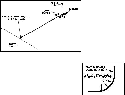
7.Hook the connector cable assembly to the cable fork on the AutoStop™ receiver cable assembly.
Attach the cable thimble to the other end of the connector cable assembly with the detent pin. (Figure 6) Run the loose end of the brake cable through the fork and thimble, double it back on itself and secure it with the two cable clamps. Place the first clamp as close as possible to the thimble and the second cable clamp about four (4) inches from the first. Before tightening the clamps adjust the cable length so there is about four (4) inches of vertical play in the cable before the towed vehicle’s braking lights come on.
8.Cut off and discard any excess cable. Recheck this adjustment after a trial run. If the towed vehicle’s brake lights come on at the slightest touch of the cable, with the cable properly adjusted, the brake lights are coming on during pedal free travel. Most brake light switches are not adjustable, so install a bungee cord from the pedal to the driver’s seat base to reduce the free travel movement of the pedal while towing.
9.Install all other safety and towing equipment as required. The AutoStop™ only actuates the towed vehicles brakes. It does not eliminate the necessity of safety chains, towing lights, transmission pumps or driveshaft disconnects.
Figure 6 |
MECHANICAL INSTALLATION NOTES
When routing the housing, do not make a turn tighter than a four (4) inch radius (Figure 7). Anchor the housing in the middle of the bend. There
are plastic cable ties and extra flag terminals included with the kit. You will also need to anchor the housing as close as possible to the end that
sticks out of the grill of the car. After you have the housing installed and the cable inserted, lay under the vehicle and have someone pull on the cable. When pressure is applied to the cable the housing will tend to try
to “straighten out” through the bends. If there are several places where
this happens, most of the cable pull will be used up straightening the housing rather than pulling on the brake pedal. Note where the housing is trying to straighten and anchor these areas.
292-2214 Rev A |
Page 4 of 12 |
10/4/13 |
 Loading...