

Page 1

TM
BrakeSafe
For Coaches w/Total Air
or Air Over Hydraulic Brakes
OPERATOR, PARTS
& INSTALLATION
MANUAL
BX88143, Pull Cylinder, BrakeSafe
Blue Ox Division, Automatic Equipment Mfg. Co. • One Mill Road, Industrial Park
Pender, Nebraska 68047 • Phone 402-385-3051 • Fax 402-385-3360 • www.blueox.us
TM
TM
Page 2
BX88143 is a proportional braking system that can be used on coaches with Total Air or Air
Over Hydraulic braking systems. With the BX88143 you will use your coach’s air brakes by
tapping into the brake relay air source. How ever hard you press on the coach’s brakes, is how
much the towed vehicle’s brakes will be applied.
Locating Air Source On Coach
1. For coaches with total air brake systems, the brake relay is located ahead of the rear axle. This relay
has four to five ports, some of which will be used. There is a right and left brake actuator hose coming from
this relay, these hoses go to the brake actuators of each rear tire of coach. There is a 3/8” O.D. pilot tubing
coming from one of the four ports coming from the brake relay. This is the SERVICE port that is the
preferred place to connect into proportional air that receives pilot air from the coach’s brake pedal. If this
port has a 3/8” hose coming from it, use the furnished tee fitting. Cut the tubing and push the tubing into
each side of the tee fitting, making sure the tubing is bottomed into the fitting. On the bottom of some relay
valves there are four ports, three are used, the other has a 1/2” pipe plug. Remove this plug and install the
furnished 1/2”pipe to 3/8” tube fitting. If your coach needs a fitting that is not supplied, most hardware
stores have brass pipe fittings. There should be no pressure coming from the port, unless the brake pedal is
pushed down. If there is, you need to look for another port. Look at Fig.2 for a detailed schematic.
2. For coaches with air over hydraulic braking systems, the air over hydraulic assembly is located in
front of front axle on the driver’s side. There is a drain plug on the bottom side of the air actuator, take this
plug out and use the supplied tube connector. Look at Fig.3 for a detailed schematic.
3/8” Tubing Installation On Coach
Push the supplied 3/8” DOT tubing into the tee fitting or the pipe to tube fitting making sure it is
bottomed into the port. Route and secure the 3/8” DOT tubing with the 13” nylon ties supplied making sure
to route away from hot parts. There is 50 ft. of tubing supplied, which should be plenty for most coaches.
Once you get to the rear of the coach with the tubing, secure the mount bracket with the 1/4” bolts, flat and
lockwashers in a convenient location on the bumper. Make sure it is the one with the larger hole. Then
mount the bulkhead fitting, 3/8 tube fitting, and QD coupler to this mount bracket as shown in Fig.7. Cut
the extra 3/8” DOT tubing off and then push into the pipe to tube fitting.
1/4” Tubing Installation On Towed
Unplug the QD plug and 1/4” bulkhead fitting from the self-coil hose assembly. If you have a Blue
Ox baseplate you can use the bracket plate to mount to your baseplate with existing bolts. Then mount
the QD plug and 1/4” bulkhead fitting to this bracket as shown in Fig.7.
If you have a baseplate other than a Blue Ox, you can use the other angle bracket supplied.
Mount this bracket with the 1/4” bolts, flat and lockwashers, and hex nuts to your baseplate. Then
mount the QD plug and 1/4” bulkhead to this bracket. Route the 1/4” tubing through the driver’s
side engine compartment using the supplied wire ties, making sure not to run tubing along hot
parts. Push tubing through an existing grommet through the firewall. If there isn’t a hole, drill a
new hole. Route the tubing to the brake pedal, making sure to leave enough to hook to the
pull cylinder that will be mounted to the brake arm. Cut the excess tubing off.
Blue Ox Division, Automatic Equipment Mfg. Co. • One Mill Road, Industrial Park
Pender, Nebraska 68047 • Phone 402-385-3051 • Fax 402-385-3360 • www.blueox.us
292-5640 4/06 1 of 12
TM
Page 3
Pull-Cylinder Installation
Loosen one of the 1 1/4” hex bolts from the mount bracket. The mount bracket will then
pivot. Loosen the other 1 1/4” hex bolt enough to get around the brake pedal arm. Place the
cylinder assembly on the brake pedal arm about 3/4” above the brake pedal. Tighten both hex
bolts equally onto the brake pedal arm making sure the 1/2” band is 90 degrees to the brake
pedal pivot axis. Look at Fig. 4 and 5. Make sure the pull cylinder is mounted 90 degrees from
brake pedal arm. Make sure 1 1/4” hex bolts are tightened firmly, so the pull cylinder is not going to
slip on the brake pedal arm. Now that the pull cylinder is mounted, finger tighten the two mount plates
onto the end of the band. Pull the 1/2” band back to the firewall keeping the band parallel to the pull
cylinder and coming straight back from the pull cylinder (See Fig. 4 & 5). Note: Not making sure to
do this will cause excessive wear of the band. Now mark where the hole will need to be drilled and
mark the brake pedal brackets with a pencil. Once marked, remove pull cylinder assembly and drill
a 7/32” hole into the firewall. Making sure there are no vital components in the way. Bolt the mount
plate w/beveled hole to the firewall with a 1/4” x 1 1/2” flat head self-tapping screw, flat washer, and
nylock hex nut. Bolt the pull cylinder assembly onto the brake pedal arm making sure it’s placed
where it was before. Using two 10-32 hex screws, bolt the band mount plate to the floor plate
loosely. Route the band through the mount plates, take up the slack and tighten screws with 5/32
wrench.
Quick Exhaust Installation
Before plugging the 1/4” tubing into the elbow fittings, you must put the quick exhaust valve in-line.
The end of the 1/4” tubing that will be going into the cylinder assembly, leave one foot, then cut it with
utility knife. Install the quick exhaust valve, making sure the little hole is going towards the pull or push
cylinder assemblies. Also make sure the tubing is pushed in all the way into the quick exhaust fittings.
Push the end of the 1/4” tubing into the cylinder pipe elbow.
Blue Ox Division, Automatic Equipment Mfg. Co. • One Mill Road, Industrial Park
Pender, Nebraska 68047 • Phone 402-385-3051 • Fax 402-385-3360 • www.blueox.us
292-5640 4/06 2 of 12
TM
Page 4
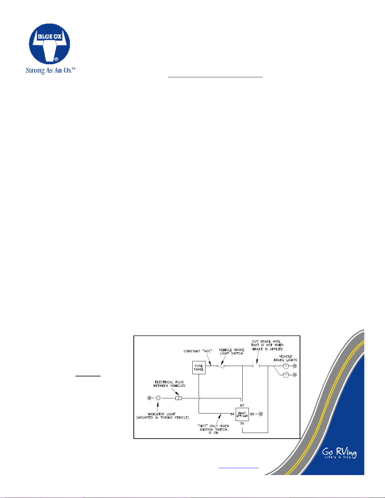
INDICATOR LIGHT INSTALLATION
The BrakeSafe uses the towed vehicles brakes. Most vehicle’s brake lights work with the key in the off and in the accessory
position. This creates the possibility of the towed vehicle’s battery being drained while towing as the brake lights are activated each
time the brake pedal is depressed by the BrakeSafe. Included are electrical parts which bypass the towed vehicles battery while
towing. The only change you will notice to the towed vehicle is that the brake lights will only be activated by the brake pedal when
the ignition is in the "on" position. We also include a light indicator that is installed in the dash of the towing vehicle which lights up
when the brake pedal in the towed vehicle is pulled on by the BrakeSafe. (Fig. 1) WARNING: Motorhome dash light MUST be
installed or warranty will be void.
1. Locate the brake light switch which is activated when the brake pedal is pressed down. Locate the hot wire into the switch and
the wire from the switch to the brake lights. You will need to splice into the wire coming from the switch to the brake lights. Cut
the wire at a convenient place and strip the two ends.
2. If there is room, you can locate the relay where you cut the wires. If there isn’t room, splice wires onto the ones you cut to give
yourself working room. Black wire and butt connectors are supplied in the parts sack.
3. Strip one end of the yellow wire and twist it together with the wire coming from the brake switch. Crimp a female spade terminal
on the twisted pair. Slide the terminal over the male terminal on the relay labeled “87”.
4. Crimp a female spade terminal on the end of the wire going the brake lights. Slide this terminal over the male terminal on the relay
labeled “30”.
5. Locate a bolt to use as a ground. Cut a piece of the black wire long enough to reach from the relay to the bolt. Strip both ends of
the black wire and crimp a ring terminal on one end and a female spade terminal on the other. Put the ring terminal under the head
of the bolt and the spade terminal on the male terminal on the relay labeled “85”.
6. In the car's fuse panel locate a fuse that is "hot" only when the ignition switch is in "on" position. Use the mini fuse tapper with
fuse, crimp a female spade terminal on the end of black wire and attach it to fuse tapper. Cut a piece of black wire to reach from
the fuse to the terminal on the relay labeled "86".
7. Route the yellow wire from the relay through the engine compartment of the car into the wiring disconnect plug. Then from the
wiring disconnect plug on the back of the coach along the bottom of the coach and into the dash of the coach. Tie the wire to the
frame of the coach with cable ties or other suitable means.
8. Locate a suitable place in the dash and drill a half (1/2) inch hole for the light indicator. Crimp a butt connector to both wires and
insert the indicator into the dash.
9. Cut the yellow wire to length and attach it to one of the wires on the indicator. Locate a bolt to use as a ground. Cut a piece of
black wire to length and connect it to the other indicator wire, crimp a ring terminal on the other end of the black wire and fasten it
to the grounding bolt.
10. Gather up the wires and the
relay. Anchor them up out of
the way so they will not
interfere with driving the
vehicle.
TESTING
The electrical installation can be
tested to see if it is installed
correctly. When applying the
brakes with the key in the off
and the accessory position, the
rear brake lights should not
come on, but when applying the
brakes with the key in the on
position, the brake lights should
come on.
Figure 1
Blue Ox Division, Automatic Equipment Mfg. Co. • One Mill Road, Industrial Park
Pender, Nebraska 68047 • Phone 402-385-3051 • Fax 402-385-3360 • www.blueox.us
292-5640 4/06 3 of 12
TM
Page 5

Testing Brake System
Connect the towed vehicle to the coach with towing system. Connect the self-coiling air line to the
coach and towed vehicle. Make sure the sleeve clicks forward on the QD coupler, this will ensure the
plug and coupler are locked. With the towed engine off, pump the brake pedal several times to deplete
vacuum or power boost in the towed vehicle’s power brakes. THIS IS VERY IMPORTANT, AS
OVER BRAKING WILL OCCUR IF NOT COMPLETELY DEPLETED!! Start the coach engine
and bring the air pressure up to pressure switch setting. Apply the coach brakes several times and
witness the brake pedal movement in the towed vehicle. Check that there are no leaks and that the
cylinder in towed vehicle operates and releases properly. Test drive the coach with towed vehicle
attached on a hardtop road. Try the brakes at several speeds above 50 MPH. You will notice the
coach is stopping as if the towed isn’t attached.
Blue Ox Division, Automatic Equipment Mfg. Co. • One Mill Road, Industrial Park
Pender, Nebraska 68047 • Phone 402-385-3051 • Fax 402-385-3360 • www.blueox.us
292-5640 4/06 4 of 12
TM
Page 6

1. UNUSED RELAY PORT
PILOT AIR FROM
BRAKE PEDAL
FITTING
AIR SOURCE LOCATION,
CUT TUBE, INSTALL TEE
OPTION 2
TOP PORT
APPLIED.
TEED INTO. ONLY TEE INTO RELAY VALVE PORTS OR
TUBING THAT HAS PRESSURE WHEN COACH BRAKES ARE
NOTE: IT IS IMPORTANT THAT ONLY SERVICE AIR BE
FIG. 2
WITH TOTAL AIR BRAKES
AIR SOURCE FOR COACHES
2. TEE INTO BRAKE HOSE PORT
OPTIONAL SERVICE AIR SOURCES
AIR TO TOWED
BRAKE SYSTEM
PROPORTIONAL
TO RIGHT BRAKE ACTUATOR
MAIN AIR IN
TO LEFT BRAKE ACTUATOR
BRAKE RELAY
PROPRTIONAL PILOT AIR
FITTING
AIR SOURCE LOCATION,
CUT TUBE, INSTALL TEE
OPTION 1
Blue Ox Division, Automatic Equipment Mfg. Co. • One Mill Road, Industrial Park
Pender, Nebraska 68047 • Phone 402-385-3051 • Fax 402-385-3360 • www.blueox.us
292-5640 4/06 5 of 12
TM
Page 7

ON DRIVER’S SIDE
AHEAD OF FRONT AXLE,
AIR OVER HYDRAULIC
ASSEMBLY IS LOCATED
FROM TUBE OR PORT WHEN BRAKE PEDAL IS APPLIED.
NOTE:
ONLY TAP INTO SERVICE BRAKE AIR. AIR SHOULD FLOW
FIG. 3
WITH AIR OVER HYDRAULIC BRAKES
AIR SOURCE FOR COACHES
CONNECTOR
HYD. MASTERCYLINDER
FRONT
SUPPLIED TUBE
AIR ACTUATOR
BOTTOM DRAIN PLUG
RUN TUBING TO
REAR OF COACH
Blue Ox Division, Automatic Equipment Mfg. Co. • One Mill Road, Industrial Park
Pender, Nebraska 68047 • Phone 402-385-3051 • Fax 402-385-3360 • www.blueox.us
292-5640 4/06 6 of 12
MAIN PORT
TM
Page 8

PULL CYLINDER MOUNT
BX88140 & BX88143
VIEWED FROM RIGHT SIDE
PEDAL
MOUNTED TO BRAKE
PULL CYLINDER
FIG. 4
SUPPLIED
WASHER & NUT
1/2” BAND
FIREWALL
HOLE TOWARDS
CYLINDER
WITH SMALL
IN 1/4” TUBING
EXHAUST VALVE
INSTALL QUICK-
HOLE
SMALL
Blue Ox Division, Automatic Equipment Mfg. Co. • One Mill Road, Industrial Park
Pender, Nebraska 68047 • Phone 402-385-3051 • Fax 402-385-3360 • www.blueox.us
292-5640 4/06 7 of 12
TM
Page 9

PULL CYLINDER
6.
TIGHTEN MOUNT BOLTS
5.
ROTATE BAND TO THE PROPER POSITION
4.
LOOSEN L-BRACKET BOLTS.
L-BRACKET
3.
MARK THIS POSITION
2.
ROTATE CYLINDER HEAD TO VERTICAL
1. INSTALL PULL CYLINDER
INSTRUCTIONS
BAND SHOULD BE VERTICAL AND 90 DEGREES TO PIVOT AXIS
INSTALLATION OF PULL CYLINDER
ON BENT BRAKE ARM
FIG. 5
BAND
BRAKE
ARM
AXIS
PIVOT
Blue Ox Division, Automatic Equipment Mfg. Co. • One Mill Road, Industrial Park
Pender, Nebraska 68047 • Phone 402-385-3051 • Fax 402-385-3360 • www.blueox.us
292-5640 4/06 8 of 12
TM
Page 10

SELF-COIL HOOK-UP
3/8” TUBE
FITTING
BRACKET
MOUNT
FROM COACH
3/8” TUBE
QD COUPLER
(MALE)
BRACKET TO COACH
MOUNT ANGLE
3/8” BULKHEAD
3/8” SELF-COIL HOSE
FIG. 6
BRACKET PLATE
FRONT VIEW OF
(FEMALE)
QD COUPLER
(10-3)
QD PLUG
FROM TOWED
1/4” TUBE
1/4” BULKHEAD
PLATE TO BASEPLATE
MOUNT
BRACKET
Blue Ox Division, Automatic Equipment Mfg. Co. • One Mill Road, Industrial Park
Pender, Nebraska 68047 • Phone 402-385-3051 • Fax 402-385-3360 • www.blueox.us
292-5640 4/06 9 of 12
TM
Page 11

Blue Ox Division, Automatic Equipment Mfg. Co. • One Mill Road, Industrial Park
Pender, Nebraska 68047 • Phone 402-385-3051 • Fax 402-385-3360 • www.blueox.us
292-5640 4/06 10 of 12
TM
Page 12

Parts List
Ref. No. Qty. Part No. Description
1 1 293-1346.............................................................................Cylinder, Pull, 2 1/8” Bore
2 1 293-1345................................................................................Piston, Pull, 2 1/8” Bore
3 1 293-1303.....................................................................................................L-bracket
4 1 293-1304.................................................................................................Mount Plate
5 1 293-1316...................................................................................................Band Plate
6 1 293-1276........................................................................................Mount Plate, Floor
7 1 105-1480.........................................................................Angle, Mount Bracket, Coach
8 1 105-1479........................................................................Angle, Mount Bracket, Towed
9 1 153-0086...........................................................................3/8 Dot Nylon Tubing, 50 Ft.
10 1 293-1318....................................................................................Air Hose, 1/4 x 10 Ft.
11 1 293-1325..............................................................................................QD Plug (11-3)
12 1 293-1322.........................................................................................QD Coupler (3103)
13 1 293-1330.........................................................................................Dust Plug, Rubber
14 1 293-1323.........................................................................................QD Coupler (3003)
15 1 293-1324..............................................................................................QD Plug (10-3)
16 1 293-1319..................................................................................1/4 T Bulkhead Adapter
17 1 293-1320.................................................................................3/8 P Bulkhead Adapter
18 2 293-1321...................................................................................Tube Fitting, 3/8 x 1/4
19 1 293-1343...................................................................................Tube Fitting, 3/8 x 1/2
20 1 293-1341......................................................................................................Tube Tee
21 1 293-1273...................................................................................Tube Fitting, 3/8 x 3/8
22 1 62-3406..............................................................................Assy, Quick Exhaust Valve
23 1 190-0131..............................................................................................Band, 1/2 x 20
24 1 293-1347................................................................................................Polypak Seal
25 1 201-0569................................................................... 1/4-20 x 3/4 Hex Bolt, Grd. 5, ZP
26 1 201-0071........................................................................1/4-20 x 1 Hex Bolt, Grd.5, ZP
27 1 201-0204...................................................................1/4-20 x 1 1/4 Hex Bolt, Grd.5, ZP
28 1 201-0673.........................................................1/4-20x 1 1/2 Hex Hd Self Tap Screw, ZP
29 2 201-0687..............................................................10-32 x 1/2 Hex Hd. Screw, Grd.5, ZP
30 1 202-0102...........................................................................1/4-20 Hex Nylock Nut, ZP
31 1 202-0001.........................................................................1/4-20 Hex Nut, Grd.5, ZP
32 3 203-0008...............................................................................1/4 Lockwasher, ZP
33 3 203-0001...............................................................................1/4 Flatwasher, ZP
Blue Ox Division, Automatic Equipment Mfg. Co. • One Mill Road, Industrial Park
Pender, Nebraska 68047 • Phone 402-385-3051 • Fax 402-385-3360 • www.blueox.us
292-5640 4/06 11 of 12
TM
Page 13

BX88143
START-UP CHECKLIST
1.CONNECT TOWED VEHICLE TO THE COACH IN THE NORMAL WAY. IF
BREAK-AWAY SYSTEM IS USED, CONNECT LANYARD WIRE BETWEEN COACH
AND TOWED VEHICLE.
2. CONNECT THE SELF-COILING AIR LINE TO THE COACH AND TOWED VEHICLE.
MAKE SURE THE SLEEVE CLICKS FORWARD ON THE QD COUPLER, THIS WILL
ENSURE THE PLUG AND COUPLER ARE LOCKED.
3. MAKE SURE ALL HOSES ARE PLUGGED IN, AND BOTTOMED INTO FITTINGS. BE
SURE TO HOOK UP THE BUNGEE CORD FROM THE BRAKE PEDAL TO THE
STEERING WHEEL COLUMN. (NOT THE ACTUAL STEERING WHEEL)
4. WITH THE TOWED ENGINE OFF, PUMP THE BRAKE PEDAL SEVERAL TIMES TO
DEPLETE VACUUM OR POWER BOOST IN THE TOWED’S POWER BRAKES. THIS
IS VERY IMPORTANT, AS OVER BRAKING WILL OCCUR IF NOT COMPLETELY
DEPLETED!!
5. START THE COACH ENGINE AND BRING THE AIR PRESSURE UP TO PRESSURE
SWITCH SETTING. APPLY THE COACH BRAKES SEVERAL TIMES AND WITNESS
THE BRAKE PEDAL MOVEMENT IN THE TOWED VEHICLE. ALSO THAT THE
INDICATOR LIGHT IS COMING ON, IF NOT, INSPECT AND FIX THE PROBLEM.
6. TURN IGNITION OF THE TOWED VEHICLE TO THE ACCESSORY POSITION, TO
UNLOCK STEERING WHEEL.
DISCONNECT CHECK LIST
1. DISCONNECT SELF-COILING HOSE AND TOW BAR FROM THE TOWED VEHICLE AND COACH. INSTALL PLUG AND CAP ON THE AIR DISCONNECTS, TO
KEEP WATER AND DIRT OUT OF THE SYSTEM.
2. DISCONNECT THE BUNGEE CORD, IF IT IS BEING USED.
THE TOWED VEHICLE IS NOW READY TO DRIVE AWAY.
Blue Ox Division, Automatic Equipment Mfg. Co. • One Mill Road, Industrial Park
Pender, Nebraska 68047 • Phone 402-385-3051 • Fax 402-385-3360 • www.blueox.us
292-5640 4/06 12 of 12
TM
 Loading...