

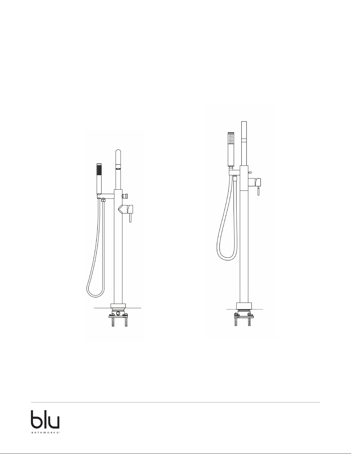
Floor-Mounted Tubfiller
Installation Guide
TSP510 TSU510
1 866 907 0122 blubathworks.com
2014-02
2012-04

Attention – Before Installation
1. Inspect this product to ensure you have all parts as shown that are required for proper installation.
2. The valve cartridge has been factory tested and adjusted – DO NOT TAKE THE CARTRIDGE APART. Taking the
cartridge apart will void the warranty.
3. Ensure that both hot and cold water feeds are properly connected to the marked lav connecting.
4. This product must be installed by a professional contractor.
5. Refer to the specification and assembly drawings attached for installation directions.
6. Flow Pressure –Min. 25 PSI, Max. 80 PSI. Recommended pressure – 50 to 60 PSI.
Installation Requirements
Please read the instructions carefully so as to avoid any damage to the fixture.
1. To ensure this product is installed properly, you must read and follow these guidelines.
2. The owner/user of the faucet must keep this information for future reference.
3. Be sure your installation conforms to local codes.
4. Refer to the specification and assembly drawings attached. Faucet is sold partially assembled but shown fully
disassembled for illustrative and service purposes only.
5. Inspect this product to ensure you have all parts required for proper installation.
6. Use only a strap wrench or protected/smooth-jaw wrench on any finished surface.
7. If possible, install the faucet assembly on the sink or mounting surface before setting.
8. Do NOT use putty during this installation.
Cleaners For Fittings And Accessories
To avoid damaging the surface and working components of the fittings, certain precautions must be taken in terms
of usage and subsequent cleaning as many cleaning agents contain acids for general cleaning and removing calcium
deposits. When caring for your fittings and accessories, please note the following:
- Only apply cleaners which are expressly intended for the use
- Never use any cleaner containing hydrochloric acid, formic acid or acetic acid on or near the fitting, as they can
cause considerable damage
- Do not use cleaners containing phosphoric acid
- Do not use cleaners containing chlorine bleach solutions
- Never mix or combine cleaning agents
- Abrasive cleaners and unsuitable scouring agents such as scouring pads
Technical Support Assistance
If further assistance is required, please contact:
Product support at 1.866.907.0122 (09:00 - 17:00hrs PST) or email
technical@blubathworks.com
North America
Blu Bathworks Inc.
188 Smithe Street, Vancouver BC, Canada, V6B 6A9
T+1.604.299.0122 F+1.604.299.0125
2014-02
1 866 907 0122 blubathworks.com
2

Installation Instructions
Recessed Concrete / Wood Floor Installation
1. Locate desired location of fixture prior to pouring concrete floor. Note: Rough-in for 510 is 41/2” (114mm) Ø and
520 is 6
2. Prior to pouring concrete floor, insert knock out in location minimum 6” x 6” (510) and 6” x 14” (520) to provide
flexibility and room for hot and cold water supply line hook up. Note: finish floor material will cover oversized
opening.
3. Depth of rough in opening should be min 2”–2
material thickness.
4. Place rough-in assembly over desired location and make marks for the placement of the mounting screws.
5. Drill a
6. Concrete floors—Insert threaded mounting screw, with the provided anchor attached, into each of the three pilot
holes so that the threading on each screw is facing upwards.
7. Wood floors—The rough-in is to be secured by lag bolts (not provided), as per install diagram.
8. Place the rough-in assembly onto the screws in the floor and adjust the small brass screws around the valve until
it is level.
9. Place a metal washer, followed by a locking washer onto the threaded part of each screw sticking above the
rough-in.
10. Tighten the rough-in into place by tightening a locking nut onto each screw over the metal washers.
11. Attach the water supply to the rough-in assembly by connecting the hot water supply on the left and the cold
12. Test the rough in connection for leaks prior to floor finish.
13. Tile the area surrounding the valve, leaving open a hole with a diameter of 75 - 90mm (3 - 31⁄2”).
14. Remove the protective plate from the top of the rough-in valve, exposing the water outlets.
15. Insert the main fixture body into the rough-in so that the supply lines plug into the water outlets.
16. Securely tighten the large brass nut at the base of the fixture body. Insert the extension tightening rod
17. Slide the escutcheon down so that it rests against the floor and completely covers the brass nut.
18. Connect one end of the shower hose to the hose attachment underneath the shower hook, and the other end
19. Push the spout into place on top of the mixer body and tighten the set screw using the provided Allen wrench.
20. Attach the horizontal control rod to the appropriate height on the connector.
21. Once everything is installed then test the fixture and make sure there are no leaks.
3
/8” x 91/2” (162mm x 241mm)
1
/2” (51-64mm) to finished floor. Note: please allow for finish floor
1
/2” (12mm) pilot hole for each mounting screw.
water supply on the right.
provided into the hole in the fastening nut and thread onto the rough in turning in a clock wise direction until
secure.
to the base of the hand-held shower head.
Technical Support Assistance
If further assistance is required, please contact:
Product Support at 1.866.907.0122 (09:00 – 17:00hrs PST) or email technical@blubathworks.com
North America
Blu Bathworks Inc.
Blu Bathworks Inc.
188 Smithe St, Vancouver, BC, Canada, V6B 6A9
3614 East 1st Ave,Vancouver, BC, Canada, V5M 1C3
T +1.604.299.0122 F +1.604.299.0125
T +1.604.299.0122 F +1.604.299.0125
1 866 907 0122 blubathworks.com
2014-02
3
 Loading...