

Blu Bathworks TEU131 User Manual

®
opus·2 electronica
Deck Mounted Basin Mixer
Installation Guide
TEU131
2013-11
1 866 907 0122 blubathworks.com

®
Attention – Before Installation
1. Inspect this product to ensure you have all parts as shown that are required for proper installation.
2. The valve cartridge has been factory tested and adjusted – DO NOT TAKE THE CARTRIDGE APART. Taking the
cartridge apart will void the warranty.
3. Ensure that both hot and cold water feeds are properly connected to the marked lav connecting.
4. This product must be installed by a professional contractor.
5. Refer to the specification and assembly drawings attached for installation directions.
6. Flow Pressure –Min. 25 PSI, Max. 80 PSI. Recommended pressure – 50 to 60 PSI.
Installation Requirements
Please read the instructions carefully so as to avoid any damage to the fixture.
1. To ensure this product is installed properly, you must read and follow these guidelines.
2. The owner/user of the faucet must keep this information for future reference.
3. Be sure your installation conforms to local codes.
4. Refer to the specification and assembly drawings attached. Faucet is sold partially assembled but shown fully
disassembled for illustrative and service purposes only.
5. Inspect this product to ensure you have all parts required for proper installation.
6. Use only a strap wrench or protected/smooth-jaw wrench on any finished surface.
7. If possible, install the faucet assembly on the sink or mounting surface before setting.
8. Do NOT use putty during this installation.
Cleaners For Fittings And Accessories
To avoid damaging the surface and working components of the fittings, certain precautions must be taken in terms
of usage and subsequent cleaning as many cleaning agents contain acids for general cleaning and removing calcium
deposits. When caring for your fittings and accessories, please note the following:
- Only apply cleaners which are expressly intended for the use
- Never use any cleaner containing hydrochloric acid, formic acid or acetic acid on or near the fitting, as they can
cause considerable damage
- Do not use cleaners containing phosphoric acid
- Do not use cleaners containing chlorine bleach solutions
- Never mix or combine cleaning agents
- Do not use abrasive cleaners and unsuitable scouring agents such as scouring pads
Technical Support Assistance
If further assistance is required, please contact:
Product support at 1.866.907.0122 (09:00 - 17:00hrs PST) or email technical@blubathworks.com
North America
Blu Bathworks Inc.
188 Smithe Street, Vancouver BC, Canada, V6B 6A9
T+1.604.299.0122 F+1.604.299.0125
2013-11
1 866 907 0122 blubathworks.com
2
®
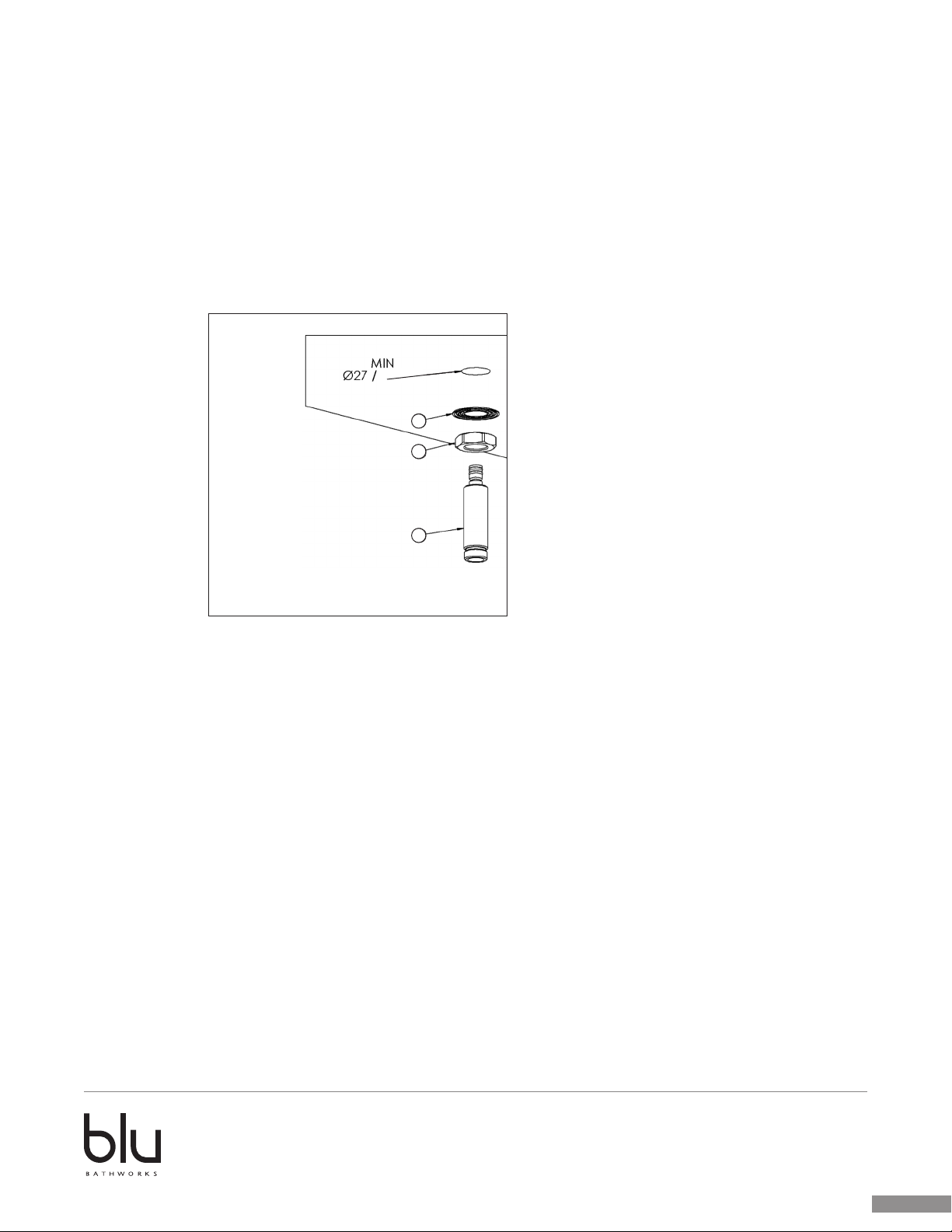
INSTALLATION STEP 1
• Before installation drill two holes, mmØ27 / inØ1,06 for the spout and
mmØ46 / inØ1,81 for the body mixer.
• Screw the nut (1) on the body mixer (3) and place the metal ring
(2).
• Screw the nut (4) on the threaded rod (6) and place the small
metal ring (5).
INSTALLATION STEP 1
• Before installation drill two holes, Ø27mm / Ø1” for the spout and Ø35mm / Ø1⅜” for the
control wheel.
• Screw the nut (2) on the threaded rod (3) and place the small metal ring (1).
1"
1
2
3
2013-11
1 866 907 0122 blubathworks.com
3
®
(6).
located under the wash basin mixer to fix the rod and the mixer
body.
INSTALLATION STEP 3
• Place the two small cover plates (1)
• Place the O-ring (2) and screw the cap (3) to secure the cover plate
of the mixer body.
• Position the O-ring (2) in its site on the nut (1).
• Screw the nut (1), as per drawing (A), on the threaded rod(3).
• Place the O-ring (4) on its site on the nut (5).
• Screw the nut (5), as shown in the drawing (A), on the mixer body
(6).
• Once the correct position of the rings is reached, tighten the nuts
located under the wash basin mixer to fix the rod and the mixer
body.
• (A)
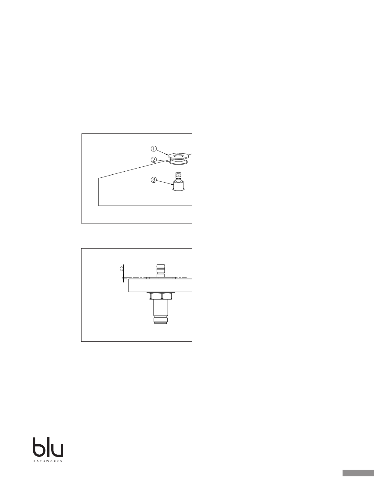
INSTALLATION STEP 3
• Place the two small cover plates (1)
• Place the O-ring (2) and screw the cap (3) to secure the cover plate
of the mixer body.
INSTALLATION STEP 2
• Position the O-ring (2) in its site on the nut (1).
• Screw the nut (1), as per drawing (A), on the threaded rod (3).
• Once the correct position of the rings is reached, tighten the nuts located under the basin
spout to fix the rod.
A.
1 866 907 0122 blubathworks.com
2013-11
4
®
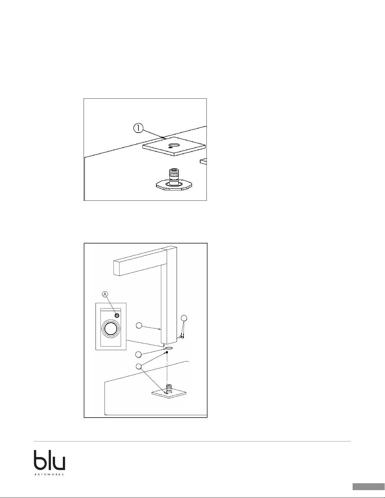
INSTALLATION STEP 3
• Place the one small cover plate (1)
INSTALLATION STEP 4
• Fix the grub screw (1) in the spout threaded hole (A)
• Place the O-ring (2) and the spout (3)
• Fix the spout with the grub screw (4)
4
3
2
1
2013-11
1 866 907 0122 blubathworks.com
5
®
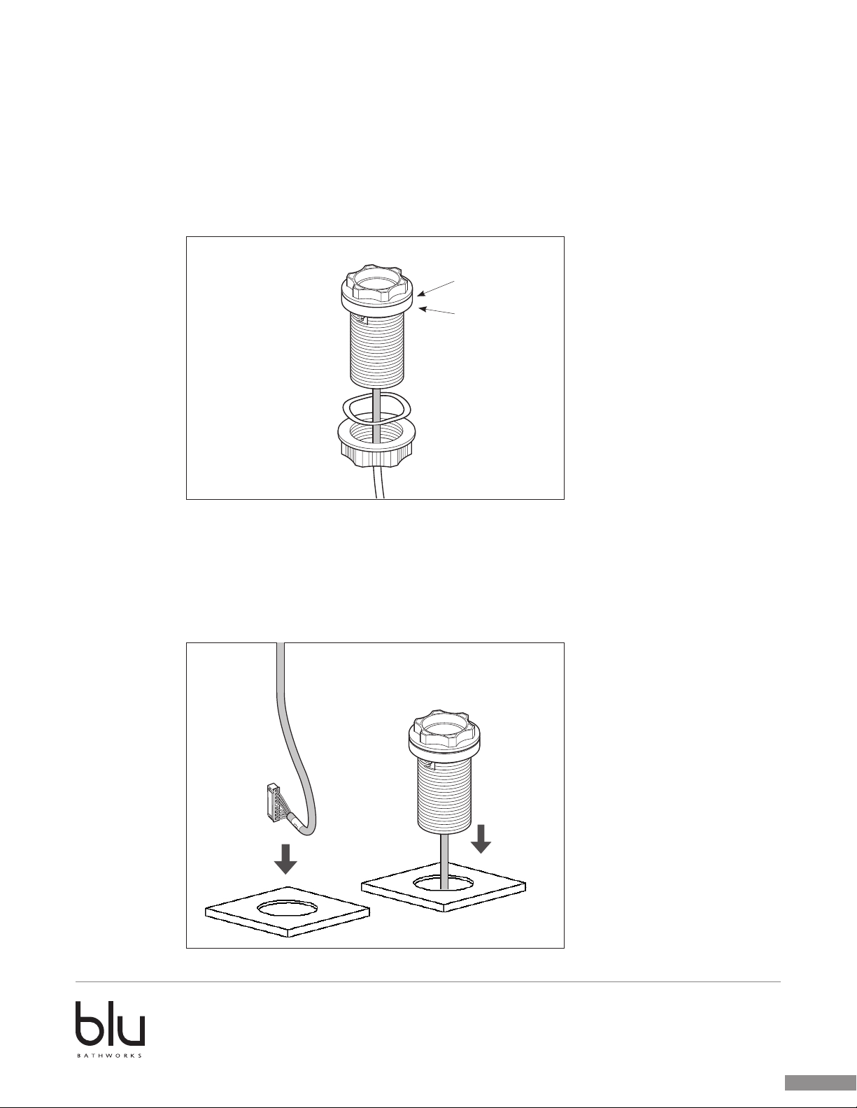
INSTALLATION STEP 5
• Unscrew and remove the nut and washer from the control brackets and data cables.
• Carefully pull the ‘front’ control wheel off the controls, taking care not to mix them up.
round trim
o-ring
INSTALLATION STEP 6
• Prepare the basin/countertop to take the control fixing brackets. 35mm/1⅜" diameter
holes are required to fit the brackets.
• Feed the control data cables through the holes, then insert the control brackets.
2013-11
1 866 907 0122 blubathworks.com
6
 Loading...