


HVĆ100E and HVĆ100G
INSTALLATION - OPERATION - MAINTENANCE
HVĆ100E et HVĆ100G
MANUEL D'INSTALLATION - FONCTIONNEMENT - ENTRETIEN
BLODGETT OVEN COMPANY
www.blodgett.com
44 Lakeside Avenue, Burlington, Vermont 05401 USA Telephone (802) 658Ć6600 Fax: (802)864Ć0183
PN 52424 Rev H (6/11)
E 2011- G.S. Blodgett Corporation

THE REPUTATION YOU CAN COUNT ON
UNE RÉPUTATION SUR LAQUELLE VOUS POUVEZ COMPTER
For over a century and a half, The Blodgett Oven Company has been building
ovens and nothing but ovens. We've set the industry's quality standard for all
kinds of ovens for every foodservice operation regardless of size, application
or budget. In fact, no one offers more models, sizes, and oven applications
than Blodgett; gas and electric, fullĆsize, halfĆsize, countertop and deck, conĆ
vection, Cook'n Hold, CombiĆOvens and the industry's highest quality Pizza
Oven line. For more information on the full line of Blodgett ovens contact your
Blodgett representative.
Cela fait maintenant dessus un siècle et demi que Blodgett se spécialise dans
la fabrication de fours. Nous avons établi les normes de qualité qui s'appliĆ
quent dans l'industrie à tous les types de fours utilisés dans les services aliĆ
mentaires, quel qu'en soit la taille, l'exploitation ou le budget. En fait, ni n'offre
plus de modèles, de tailles et d'applications de fours que Blodgett. À gaz et
électriques. De tailles différentes, sur plan de travail et superposables. Qu'il
s'agisse de fours à convection, des modèles Cook'n Hold et CombiĆOven, ou
de la gamme de fours à pizzas de la plus haute qualité offerte sur le marché.
Pour de plus amples informations sur la gamme complète de fours Blodgett,
veuillez contacter votre représentant Blodgett.

IMPORTANT
WARNING: IMPROPER INSTALLATION, ADJUSTMENT, ALTERATION, SERVICE OR
MAINTENANCE CAN CAUSE PROPERTY DAMAGE, INJURY OR DEATH. READ THE
INSTALLATION, OPERATING AND MAINTENANCE INSTRUCTIONS THOROUGHLY
BEFORE INSTALLING OR SERVICING THIS EQUIPMENT
AVERTISSEMENT: UNE INSTALLATION, UN AJUSTEMENT, UNE ALTÉRATION, UN
SERVICE OU UN ENTRETIEN NON CONFORME AUX NORMES PEUT CAUSER DES
DOMMAGES À LA PROPRIÉTE, DES BLESSURES OU LA MORT. LISEZ ATTENTIVEĆ
MENT LES DIRECTIVES D'INSTALLATION, D'OPÉRATION ET D'ENTRETIEN AVANT
DE FAIRE L'INSTALLATION OU L'ENTRETIEN DE CET ÉQUIPEMENT.
FOR YOUR SAFETY
Do not store or use gasoline or other flammable vapors or liquids in the vicinity
of this or any other appliance.
AVERTISSEMENT
Ne pas entreposer ni utiliser de l'essence ni d'autres vapeurs ou liquides inflamĆ
mables dans le voisinage de cet appariel, ni de tout autre appareil.
The information contained in this manual is important for the proper installation,
use, and maintenance of this oven. Adherence to these procedures and instrucĆ
tions will result in satisfactory baking results and long, trouble free service.
Please read this manual carefully and retain it for future reference.
Les informations données dans le présent manuel sont importantes pour installer,
utiliser et entretenir correctement ce four. Le respect de ces instructions et procéĆ
dures permettra d'obtenir de bons résultats de cuisson et une longue durée de serĆ
vice sans problèmes. Veuillez lire le présent manuel et le conserver pour pouvoir
vous y reporter à l'avenir.
Errors: Descriptive, typographic or pictorial errors are subject to correction. SpecificaĆ
tions are subject to change without notice.
Erreurs:Les erreurs de description, de typographie ou d'illustration font l'objet de
corrections. Les caractéristiques sont sujettes à modifications sans préavis.

Your Service Agency's Address:
Adresse de votre agence de service:
Model/Modèl:
Serial Number/Numéro de série:
Your appliance was installed by/
Installateur de votre four:
Your oven's installation was checked by/
Contrôleur de l'installation de votre four:

Table of Contents/Table des Matières
Introduction
Oven Description & Specifications 2. . . . . .
Installation
Agency Approvals 4. . . . . . . . . . . . . . . . . . . .
Oven Location and Ventilation 5. . . . . . . . . .
Leg Attachment 6. . . . . . . . . . . . . . . . . . . . . .
Caster Attachment 7. . . . . . . . . . . . . . . . . . . .
Stacking 8. . . . . . . . . . . . . . . . . . . . . . . . . . . . .
Plumbing Connections 9. . . . . . . . . . . . . . . .
Electrical Connections 10. . . . . . . . . . . . . . . .
Gas Connections 11. . . . . . . . . . . . . . . . . . . . .
Gas Hose Restraint 13. . . . . . . . . . . . . . . . . . .
Operation
Safety Information for Gas Units 14. . . . . . . .
Standard Control 15. . . . . . . . . . . . . . . . . . . . .
MenuSelectt Control 17. . . . . . . . . . . . . . . . .
Touchscreen Control 23. . . . . . . . . . . . . . . . . .
Maintenance
Spray Bottle Operating Procedure 33. . . . . .
Cleaning and Preventive Maintenance 34. . .
Introduction
Description du four et Spécifications 36. . . .
Installation
Certifications 38. . . . . . . . . . . . . . . . . . . . . . . . .
Emplacement du four et mise de
niveau et Ventilation 39. . . . . . . . . . . . . . . . . . .
Montage des pieds 40. . . . . . . . . . . . . . . . . . .
Accessoire des roulettes 41. . . . . . . . . . . . . .
Superposition 42. . . . . . . . . . . . . . . . . . . . . . . .
Raccordement de la plomberie 43. . . . . . . . .
Raccordement à l'électricité 44. . . . . . . . . . . .
Raccordement au gaz 45. . . . . . . . . . . . . . . . .
Câble d'immobilisation du tuyau à gaz 47. .
Fonctionnement
Renseignements sur la sécurité des
appareils au gaz 48. . . . . . . . . . . . . . . . . . . . . .
Commandes standard 49. . . . . . . . . . . . . . . .
Commande MenuSelectt 51. . . . . . . . . . . . .
Touchscreen Control 59. . . . . . . . . . . . . . . . . .
Entretien
Procédure de fonctionnement du
pulvérisateur 69. . . . . . . . . . . . . . . . . . . . . . . . .
Nettoyage et entretien préventif 70. . . . . . . .
Introduction
Oven Description & Specifications
ABOUT THE HYDROVECTION
Blodgett Hydrovection ovens are quality proĆ
duced using highĆgrade stainless steel with first
class workmanship.
The multiple speed fan, which is guarded against
accidental finger contact, is driven by a quiet and
powerful motor. The condenser draws out excess
moisture from the appliance. Condensation and
waste water, which result during hydro cooking
and cleaning, are continuously drained.
The use of high quality insulation impedes excesĆ
sive heat radiation and saves energy.
The Hydrovection has optional adjustable legs
which adapt easily to slightly uneven surfaces and
optional floor stands which are designed for use
with all of the table models.
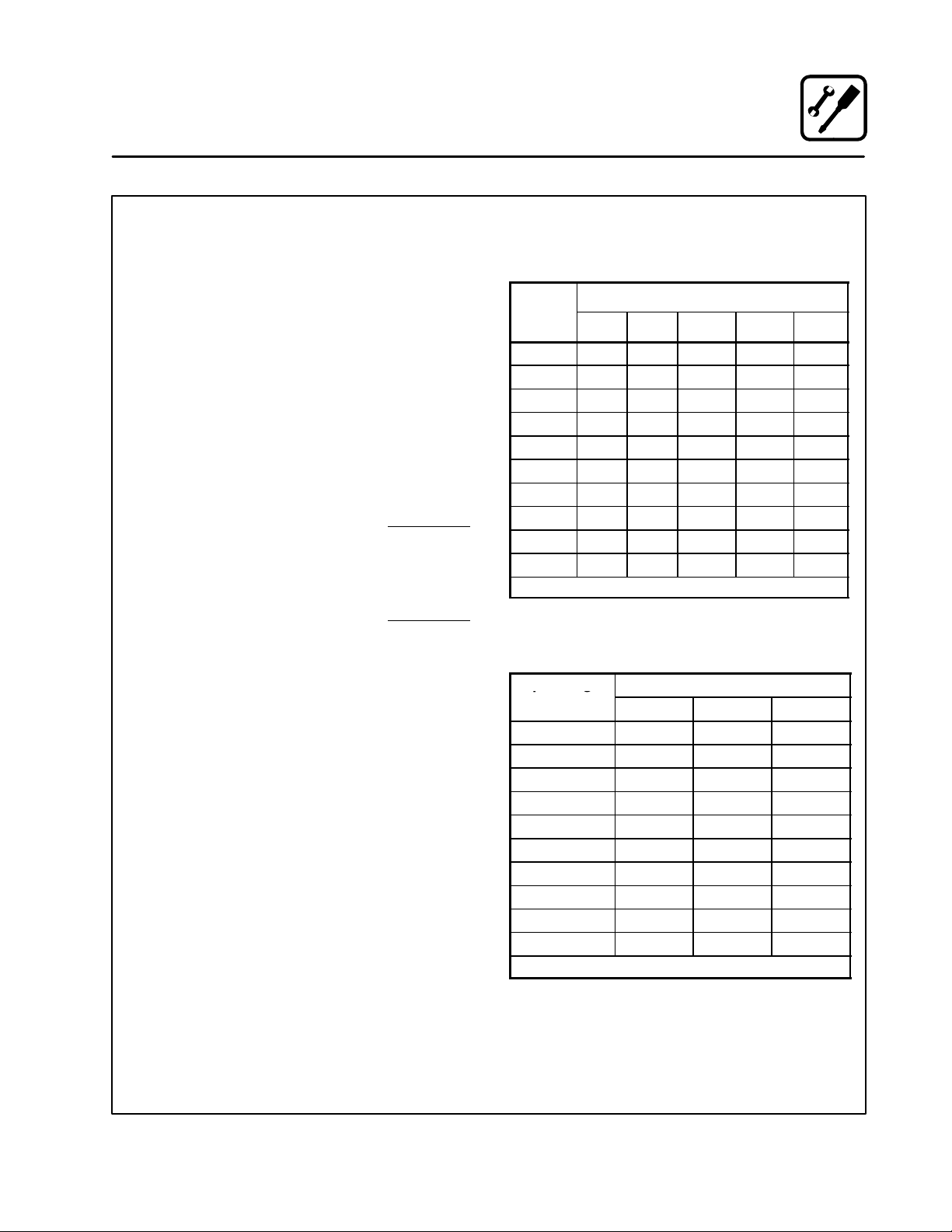
PLUMBING SPECIFICATIONS
WATER
Water Pressure 30 PSI (207 kPa) minimum
50 PSI (345 kPa) maximum
Water Connection 3/4" garden hose - Cold water only
The practical oven doors, with viewing windows,
have a wide swing radius and handle which can be
operated easily, even with wet or greasy hands.
Ease of operation is guaranteed through the simĆ
ple arrangement of the controls. Graphic symbols
make the appliance easy for even inexperienced
kitchen staff to operate. A third function, the Cool
Down mode, allows the oven cavity to cool down
rapidly with the door opened.
Cleaning is kept to a minimum. The interior is
sprayed with a selfĆacting cleaning solution which
interacts with humidity to easily remove crusts and
stains. The oven is designed for easy care and is
welded water tight so that the internal cooking
cavity may be rinsed with a hose after the cleaning
process.
Water Pressure
Regulator Setting
Minimum Requirements TDS - less than 100 parts per million
DRAINAGE
Drain Type Atmospheric Vented Drain
Drain Connection 1" NPT Male
Avg Water Drain Temp. Approximately 140_F (60_C)
Preset to 30 PSI (207 kPa)
Total Hardness - 80Ć120 parts per million
Chlorides - less than 30 parts per million
Chlorine - 0 parts per million
pH Factor - 7.0Ć8.0
2
Introduction
Oven Description & Specifications
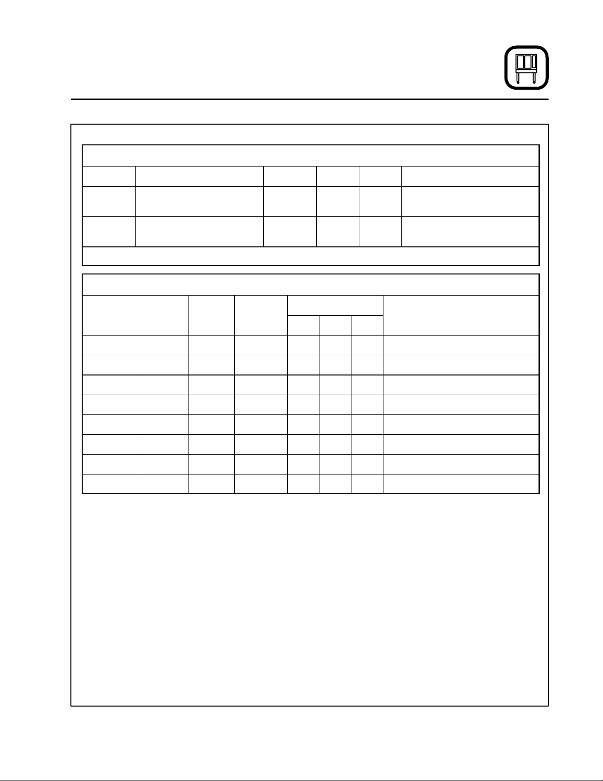
RATINGS - HVĆ100G
Gas Type Gas Input Voltage Phase Amps Motor
Natural 60,000 BTU/Hr 120 1 20 1/2 HP 208Ć240VAC, 3 phase,
50/60 Hz
Propane 60,000 BTU/Hr 120 1 20 1/2 HP 208Ć240VAC, 3 phase,
50/60 Hz
3/4" NPT connector for all U.S. and Canadian installations
RATINGS - HVĆ100E
Voltage Hz kW Phase
208 60 15 3 38 38 38 1/2 HP 208Ć240VAC, 50/60 Hz
240 60 15 3 36 34 34 1/2 HP 208Ć240VAC, 50/60 Hz
440 60 15 3 20 18 18 1/2 HP 208Ć240VAC, 50/60 Hz
480 60 15 3 18 17 17 1/2 HP 208Ć240VAC, 50/60 Hz
208 60 13 3 33 33 36 1/2 HP 208Ć240VAC, 50/60 Hz
240 60 13 3 31 29 29 1/2 HP 208Ć240VAC, 50/60 Hz
440 60 13 3 16 16 17 1/2 HP 208Ć240VAC, 50/60 Hz
480 60 13 3 15 15 16 1/2 HP 208Ć240VAC, 50/60 Hz
Max Load (amps)
L1 L2 L3
Motor
3
Installation
Agency Approvals
THE INSTALLATION INSTRUCTIONS CONĆ
TAINED HEREIN ARE FOR THE USE OF QUALIĆ
FIED INSTALLATION AND SERVICE PERSONNEL
ONLY. INSTALLATION OR SERVICE BY OTHER
THAN QUALIFIED PERSONNEL MAY RESULT IN
DAMAGE TO THE OVEN AND/OR INJURY TO
THE OPERATOR.
Qualified installation personnel are individuals, a
firm, a corporation, or a company which either in
person or through a representative are engaged
in, and are responsible for:
D The installation or replacement of gas piping.
The connection, installation, repair or servicing
of equipment.
D The installation of electrical wiring from the elecĆ
tric meter, main control box or service outlet to
the electric appliance.
Qualified installation personnel must be experiĆ
enced in such work, be familiar with all precauĆ
tions required and have complied with all requireĆ
ments of state or local authorities having
jurisdiction.
U.S. and Canadian Installations
Installation must conform with local codes, or in
the absence of local codes, with the National Fuel
Gas Code, NFPA54/ANSI Z223.1-Latest Edition,
the Natural Gas Installation Code CAN/CGAĆ
B149.1 or the Propane Installation Code, CAN/
CGAĆB149.2 as applicable.
Reference: National Electrical Code, ANSI/NFPA
70-Latest Edition and/or Canadian Electrical
Code CSA C22.1 as applicable.
This equipment is to be installed in compliance
with the Basic Plumbing Code of the Building OffiĆ
cials and Code Administrators International Inc.
(BOCA) and the Food Service Sanitation Manual of
the Food and Drug Administration (FDA).
Appliance is to be installed with backflow prevenĆ
tion in accordance with applicable federal, provĆ
ince and local codes.
General Export Installations
Installation must conform with Local and National
installation standards. Local installation codes and/
or requirements may vary. If you have any questions
regarding the proper installation and/or operation of
your appliance, please contact your local distributor.
If you do not have a local distributor, please call
Blodgett at 0011Ć802Ć658Ć6600.
4
Installation
Oven Location and Ventilation
OWNER'S RESPONSIBILITIES
Installation responsibilities prior to service
startup inspection
You are entitled to a free startĆup inspection serĆ
vice by our factory ASAP. Before a factory repreĆ
sentative arrives to perform a startup procedure,
the owner must already have satisfied the followĆ
ing requirements.
1. Oven(s) are uncrated, stacked (if applies) and
put in place.
NOTE: Please refer to Leg Attachment and
Stacking.
Maximum shelf loading - 60 lbs (27.3 Kg)
OVEN LOCATION
The well planned and proper placement of your
oven will result in long term operator convenience
and satisfactory performance.
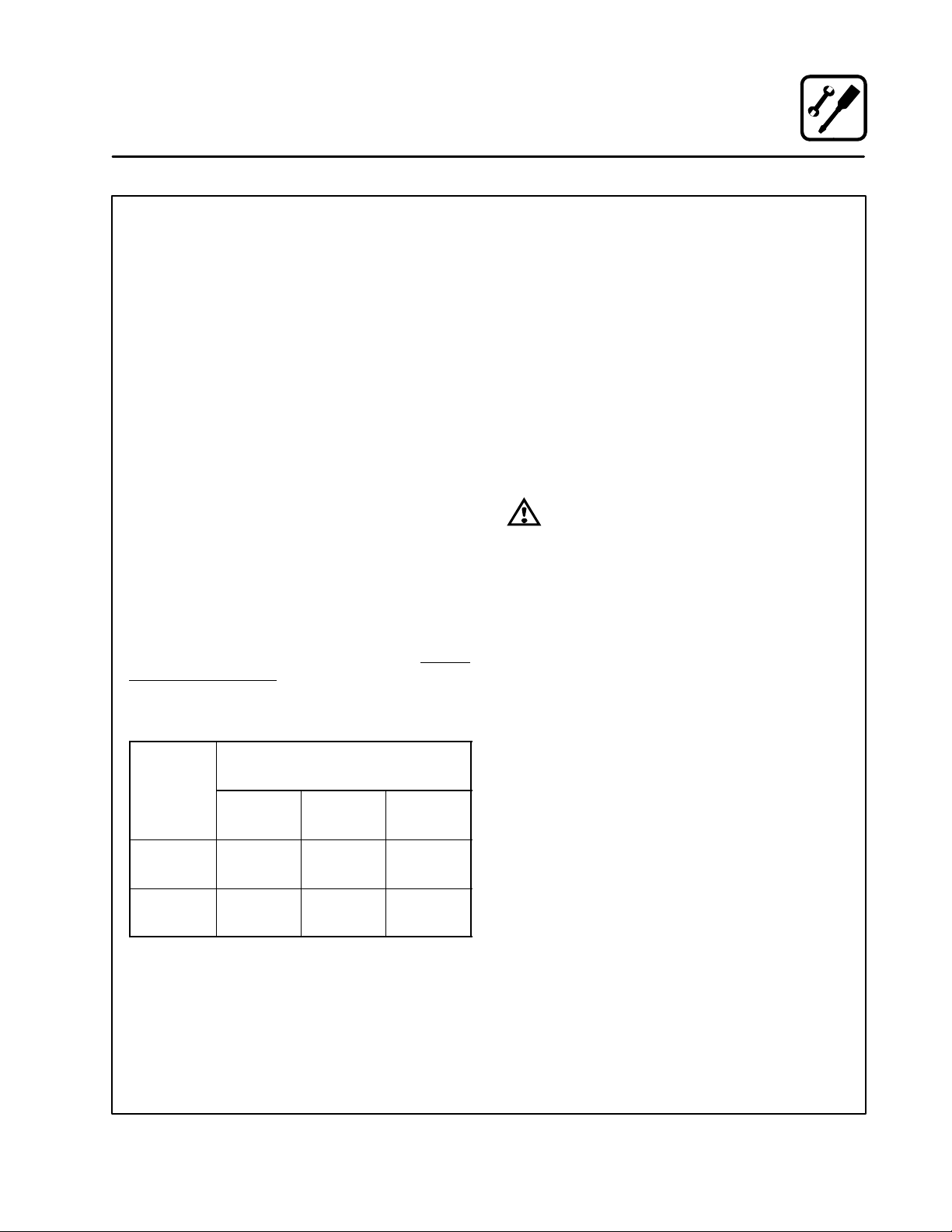
Certain minimum clearances must be maintained
between the oven and any combustible or nonĆ
combustible construction. See the table below.
In addition, the following clearances are recomĆ
mended for servicing.
D Oven body sides - 12" (30cm)
D Oven body back - 12" (30cm)
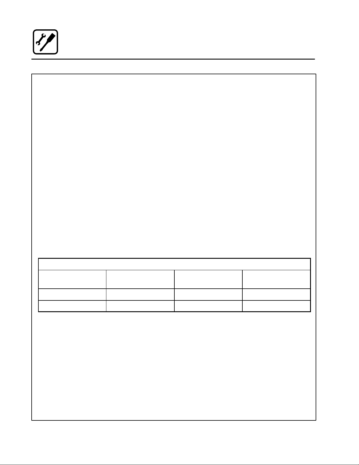
MINIMUM REQUIRED
Oven
Model
Right
Side
HVĆ100E 0"
(0mm)
HVĆ100G 0"
(0mm)
CLEARANCES
Left
Side
0"
(0mm)6"(152.4mm)
0"
(0mm)6"(152.4mm)
Back
VENTILATION
The necessity for a properly designed and inĆ
stalled ventilation system cannot be over emphaĆ
sized. The ventilation system will allow the unit to
function properly while removing unwanted vaĆ
pors and products of combustion from the operatĆ
ing area.
The appliance must be vented with a properly deĆ
signed mechanically driven exhaust hood. The
hood should be sized to completely cover the
equipment plus an overhang of at least 6" (15 cm)
on all sides not adjacent to a wall. The capacity of
the hood should be sized appropriately and proviĆ
sions made for adequate makeup air.
WARNING!!
Failure to properly vent the oven can be
hazardous to the health of the operator;
and will result in operational problems,
unsatisfactory baking, and possible damĆ
age to the equipment. Damage sustained
as a direct result of improper ventilation
will not be covered by the Manufacturer's
warranty.
When installed in the Commonwealth of MassaĆ
chusetts, this appliance must be interlocked with
the hood exhaust system so that the appliance
may be operated only when the hood exhaust sysĆ
tem is running.
U.S. and Canadian Installations
Refer to your local ventilation codes. In the abĆ
sence of local codes, refer to the National ventilaĆ
tion code titled, Standard for the Installation of
Equipment for the Removal of Smoke and Grease
Laden Vapors from Commercial Cooking EquipĆ
ment", NFPAĆ96Ć Latest Edition.
General Export Installations
Installation must conform with Local and National
installation standards. Local installation codes
and/or requirements may vary. If you have any
questions regarding the proper installation and/or
operation of your unit, please contact your local
distributor. If you do not have a local distributor,
please call Blodgett at 0011Ć802Ć860Ć3700.
5
Installation
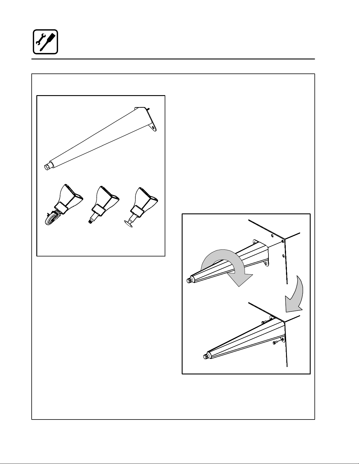
Leg Attachment
LEG OPTIONS
25" (635mm) Adjustable Leg
Casters, Adjustable Feet, or Seismic Feet
ATTACHMENT
1. Align the threaded stud on one of the front
legs to the bolt āholeā locatedāāā ināā ātheāā bottom ācorĆ
ner of the appliance. Turn the leg clockwise
and tighten to the nearest full turn.
2. Align the leg plate holes with the bolt holes.
Secure with the two 1/2" bolts provided.
3. Repeat the above steps with the other front
leg. If casters are used, install them with the
locking casters in the front of the oven. The rear
casters do not lock. Ensure that the locks are
set on the front casters.
4. Tip the oven up on the newly installed front
legs. If ācastersā are āused, checkā thatā the locksā
areā setā on ātheā front casters. āRepeat āthe above
steps for the rear legs.
5. Level the oven by screwing the adjustable feet
in or out as necessary.
8Ć1/2" (216mm) Leg with
Figure 1
Figure 2
6
Installation
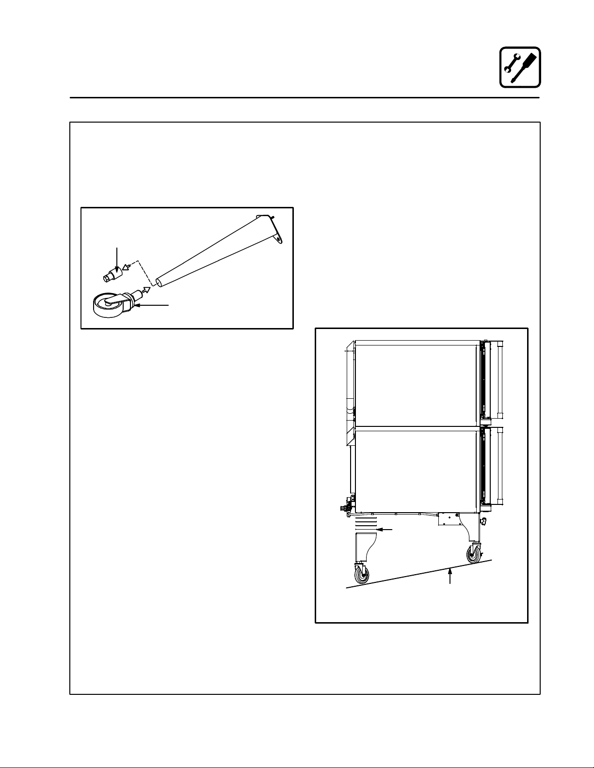
Caster Attachment
CASTERS FOR SINGLE OVENS
1. Attach the legs as described.
2. Pry the adjustable feet out of the legs.
3. Insert one caster into each leg as shown.
Tighten the lock nuts to secure the casters.
Adjustable
Leg Foot
Caster Assembly
Figure 3
PROFILE CASTERS FOR DOUBLE STACK
OVENS
1. Place a level on the floor where the casters are
to rest.
2. Place shims under the low side until it is level.
3. Mount the shims between the casters and the
oven as follows:
a.) Align the shims and caster holes with the
bolt holes.
b.) Secure with the 1/2" bolts provided.
NOTE: Install them with the locking casters in
the front of the oven. The rear casters
do not lock. Ensure that the locks are
set on the front casters.
4. Tip the oven up on the newly installed casters.
Add shims
as necessary
Floor
Exaggerated for clarity
Figure 4
7
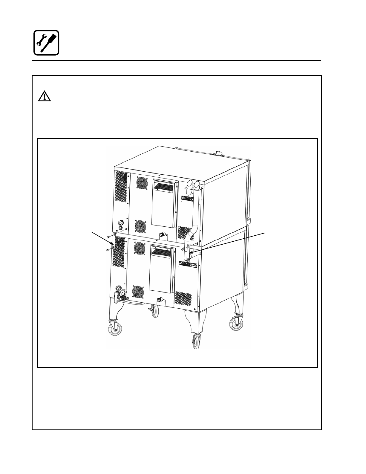
Stacking
WARNING!!
Stacking should be performed by qualiĆ
fied installation personnel only. The
ovens are heavy. Take care to use proper
tools and techniques when lifting and
stacking units.
Installation
1. Attach the legs or casters to the bottom oven.
See page 6 or 7.
2. Place the top oven on the bottom oven. Be
sure all four sides are flush.
3. Bolt the two ovens together from behind using
the stacking brackets.
Stacking
Bracket
Stacking
Bracket
Rear View HVĆ100E
Figure 5
8
WATER CONNECTION
NOTE: Must use COLD WATER ONLY.
Connect the appliance to quality water via a presĆ
sure hose with 3/4" GHT (19mm) couplings. See
Figure 6 for connections. A shut off valve is to be
provided adjacent to the oven.
WARNING!!
Operating the appliance without a water
pressure regulator installed will invalidate
your warranty.
This product must be installed by a licensed
Plumber or Gas Fitter when installed within the
Commonwealth of Massachusetts.
DRAIN CONNECTION
The drain should be run to an open floor drain
avoiding flexible hose that could sag and allow
trapped water to accumulate. The customer must
supply the piping from the oven to the drain.
Specific water/drain connection for City of Los
Angeles
1. Each drain line from the appliance shall be
routed without dips or sags to terminate above
the flood level rim of an approved indirect waste
receptor.
2. The appliance shall be installed in accordance
with the manufacturer's printed instructions
and the LAPC and LAMC, 1999 editions.
3. A backflow protection device may be required
by local codes. If so, install on the potable water
system directly ahead of the appliance. The
backflow protection device shall be any of the
following: an approved pressure type vacuum
breaker installed at least 12" above the highest
point of use, a double check valve backflow preĆ
venter or a reduced pressure principal backflow
preventer.
Installation
Plumbing Connections
A
C
A
B
C
D
A = Electrical Connection
B = Gas Connection
C = Water Connection
Filtered Water highly recommended
D = Drain Connection
HVĆ100E
D
HVĆ100G
Figure 6
9
Installation
Electrical Connections
All Models
NOTE: Electrical connections must be performed
by a qualified installer only.
Before making any electrical connections to these
appliances, check that the power supply is adeĆ
quate for the voltage, amperage, and phase reĆ
quirements stated on the rating name plate
mounted on the appliance.
The circuit breaker that is used to provide power
to this appliance must have a minimum of .076"
(3mm) contact spacing. The circuit breaker must
meet all Local and National installation standards.
All appliances must be installed in accordance
with Local or National Electrical codes.
A wiring schematic is located on the inside of the
removeable side panel.
NOTE: Disconnect the power supply to the apĆ
pliance before servicing.
WARNING!!
Improper installation may invalidate your
warranty.
Electric Models
A strain relief for the power supply cord is provided.
The installer must supply a cord that meets all Local
and National installation standards.
Gas Models
U.S. and Canadian Installations
A power cord (115V units only) is supplied with a
plug attached. Plug the power cord into the deĆ
sired receptacle.
WARNING!!
If the supply cord is damaged, it must be
replaced by a special cord or assembly
available from the manufacturer or its serĆ
vice agent.
10
Installation
L
th
pg
Gas Connections
GAS PIPING
A properly sized gas supply system is essential for
maximum oven performance. Piping should be
sized to provide a supply of gas sufficient to meet
the maximum demand of all appliances on the line
without loss of pressure at the equipment.
Example:
NOTE: BTU values in the following example are
for natural gas.
You purchase a BCXĆ14G to add to your existing
cook line.
1. Add the BTU rating of your current appliances.
Pitco Fryer 120,000 BTU
6 Burner Range 60,000 BTU
Deck Oven 50,000 BTU
Total 230,000 BTU
2. Add the BTU rating of the new oven to the toĆ
tal.
Previous Total 230,000 BTU
HVĆ100G 60,000 BTU
New Total 290,000 BTU
3. Measure the distance from the gas meter to
the cook line. This is the pipe length. Let's say
the pipe length is 30' (9 m) and the pipe size
is 1" (2.54 cm).
4. Use the appropriate table to determine the toĆ
tal capacity of your current gas piping.
The total capacity for this example is 375,000
BTU. Since the total required gas pressure,
290,000 BTU is less than 375,000 BTU, the
current gas piping will not have to be inĆ
creased.
NOTE: The BTU capacities given in the tables are
for straight pipe lengths only. Any elbows
or other fittings will decrease pipe capaciĆ
ties. For example: a schedule 40 1Ć1/2" ell
fitting has an equivalent capacity of 4.2"
(10.2 cm) of straight pipe. Contact your loĆ
cal gas supplier if you have any questions.
Maximum Capacity of Iron Pipe in Cubic Feet
of Natural Gas Per Hour
(Pressure drop of 0.5 Inch W.C.)
Pipe
eng
(ft)
10 360 680 1400 2100 3950
20 250 465 950 1460 2750
30 200 375 770 1180 2200
40 170 320 660 990 1900
50 151 285 580 900 1680
60 138 260 530 810 1520
70 125 240 490 750 1400
80 118 220 460 690 1300
90 110 205 430 650 1220
100 103 195 400 620 1150
From the National Fuel Gas Code Part 10 Table 10Ć2
Maximum Capacity of Pipe in Thousands of
BTU/hr of Undiluted P.P. Gas at 11" W.C.
Pipe Length
From the National Fuel Gas Code Part 10 Table 10Ć15
3/4" 1" 1Ć1/4" 1Ć1/2" 2"
(Pressure drop of 0.5 Inch W.C.)
(ft)
10 608 1146 3525
20 418 788 2423
30 336 632 1946
40 287 541 1665
50 255 480 1476
60 231 435 1337
70 215 404 1241
80 198 372 1144
90 187 351 1079
100 175 330 1014
Nominal Size, Inches
Inside Diameter, Inches
3/4" 1" 1Ć1/2"
11
Installation
Gas Connections
PRESSURE REGULATION AND TESTING
The gas pressure to the appliance must be rated
for each appliance while the burners are on. A sufĆ
ficient gas pressure must be present at the inlet to
satisfy these conditions. Refer to the table below
for correct gas pressure.
Each appliance has been adjusted at the factory
to operate with the type of gas specified on the ratĆ
ing plate.
Each oven is supplied with a regulator to maintain
the proper gas pressure. The regulator is essenĆ
tial to the proper operation of the oven and
should not be removed.
DO NOT INSTALL AN ADDITIONAL REGULATOR
WHERE THE UNIT CONNECTS TO THE GAS
SUPPLY UNLESS THE INLET PRESSURE IS
GREATER THAN 14" W.C. (1/2 PSI) (37mbar).
The oven and its individual shutoff valve must be
disconnected from the gas supply piping system
during any pressure testing of that system at test
pressures in excess of 1/2 psig (3.45kPa).
The oven must be isolated from the gas supply
piping system by closing its individual manual
shutoff valve during any pressure testing of the
gas piping system at test pressures equal or less
than 1/2 psig (3.45kPa).
Prior to connecting the appliance, gas lines
should be thoroughly purged of all metal filings,
shavings, pipe dope, and other debris. After conĆ
nection, the appliance must be checked for corĆ
rect gas pressure.
U.S. and Canadian Installations
Installation must conform with local codes, or in
the absence of local codes, with the National Fuel
Gas Code, NFPA54/ANSI Z223.1-Latest Edition,
the Natural Gas Installation Code CAN/CGAĆ
B149.1 or the Propane Installation Code, CAN/
CGAĆB149.2 as applicable.
General Export Installations
Installation must conform with Local and National
installation standards. Local installation codes and/
or requirements may vary. If you have any questions
regarding the proper installation and/or operation of
your appliance, please contact your local distributor.
If you do not have a local distributor, please call
Blodgett Combi at 0011Ć802Ć860Ć3700.
GAS PRESSURE - HVĆ100G
Gas
Type
Natural 7" W.C. .085" dia 3.5" W.C.
Propane 14" W.C. .063" dia 10" W.C.
Inlet
Pressure
Orifice Size at Sea
Level
Manifold Pressure
12
Installation
Gas Hose Restraint
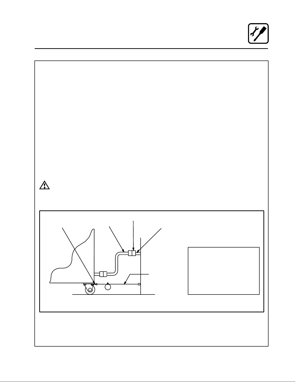
If the appliance is mounted on casters, a commerĆ
cial flexible connector with a minimum of 3/4" (1.9
cm) inside diameter must be used along with a
quick connect device.
A restraint must be used to limit the movement of
the appliance so that no strain is placed upon the
flexible connector. The restraint should be fasĆ
tened to the base frame of the oven as close to the
flexible connector as possible. It should be short
enough to prevent any strain on the connector.
With the restraint fully stretched the connector
should be easy to install and quick connect.
The restraint (ie: heavy gauge cable) should be atĆ
tached without damaging the building. DO NOT
use the gas piping or electrical conduit for the atĆ
tachment of the permanent end of the restraint!
Use anchor bolts in concrete or cement block. On
wooden walls, drive hi test wood lag screws into
the studs of the wall.
WARNING!!
If the restraint is disconnected for any reaĆ
son it must be reconnected when the apĆ
pliance is returned to its original position.
U.S. and Canadian installations
The connector must comply with the Standard for
Connectors for Movable Gas Appliances, ANSI
Z21.69 or Connectors For Moveable Gas ApĆ
pliances CAN/CGAĆ6.16 and a quick disconnect
device that complies with the Standard for QuickĆ
Disconnect Devices for Use With Gas Fuel, ANSI
Z21.41 or Quick Disconnect For Use With Gas Fuel
CAN 1Ć6.9. Adequate means must be provided to
limit the movement of the appliance without deĆ
pending on the connection and the quick disconĆ
nect device or its associated piping.
A drip leg must be used at each appliance. Refer
to NFPA54/ANSI Z223.1 Ć Latest Edition (National
Fuel Gas Code) for proper drip leg installation.
General export installations
Installation must conform with Local and National
installation standards. Local installation codes and/
or requirements may vary. If you have any questions
regarding the proper installation and/or operation of
your appliance, please contact your local distributor.
If you do not have a local distributor, please call
Blodgett Combi at 0011Ć802Ć860Ć3700.
Attachment Plate
(secure with leg mount bolt)
Gas Hose
Quick Connect
Gas Supply Line
Restraint
Installation of Gas Hose and Restraint
(Single Section Shown)
Figure 7
IMPORTANT: Cable restraint should
be fastened as close as possible to the
flexible connector and short enough to
prevent any strain on the flexible conĆ
nector.
At maximum stretch of shortened reĆ
straint, the flexible connector should
be easy to install and quick to connect.
13
Operation
Safety Information for Gas Units
THE INFORMATION CONTAINED IN THIS SECĆ
TION IS PROVIDED FOR THE USE OF QUALIFIED
OPERATING PERSONNEL. QUALIFIED OPERATĆ
ING PERSONNEL ARE THOSE WHO HAVE
CAREFULLY READ THE INFORMATION CONĆ
TAINED IN THIS MANUAL, ARE FAMILIAR WITH
THE FUNCTIONS OF THE OVEN AND/OR HAVE
HAD PREVIOUS EXPERIENCE WITH THE OPĆ
ERATION OF THE EQUIPMENT DESCRIBED. ADĆ
HERENCE TO THE PROCEDURES RECOMĆ
MENDED HEREIN WILL ASSURE THE
ACHIEVEMENT OF OPTIMUM PERFORMANCE
AND LONG, TROUBLEĆFREE SERVICE.
Please take the time to read the following safety
and operating instructions. They are the key to the
successful operation of your Blodgett Combi apĆ
pliance.
SAFETY TIPS
For your safety read before operating
What to do if you smell gas:
D DO NOT try to light any appliance.
D DO NOT touch any electrical switches.
D Use an exterior phone to call your gas supplier
immediately.
D If you cannot reach your gas supplier, call the
fire department.
What to do in the event of a power failure:
D Turn all switches to off.
D DO NOT attempt to operate the appliance until
the power is restored.
NOTE: In the event of a shutĆdown of any kind, alĆ
low a five (5) minute shut off period before
attempting to restart the oven.
General safety tips:
D DO NOT use tools to turn off the gas control. If
the gas cannot be turned off manually do not try
to repair it. Call a qualified service technician.
D If the oven needs to be moved for any reason,
the gas must be turned off and disconnected
from the appliance before removing the reĆ
straint cable. Reconnect the restraint after the
oven has been returned to its original location.
D DO NOT remove the control panel cover unless
the oven is unplugged.
14
Operation
Standard Control
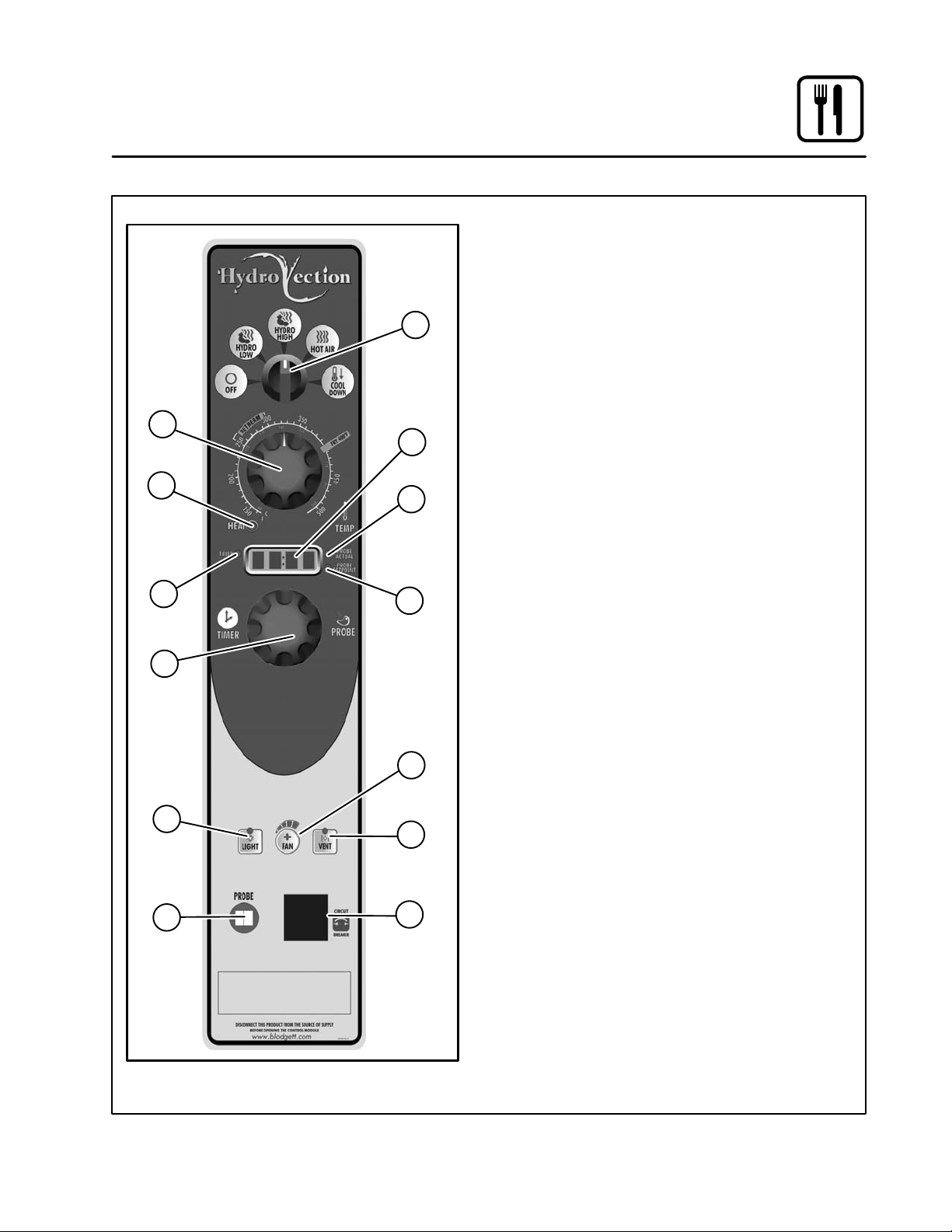
CONTROLS IDENTIFICATION
1. MODE SELECTOR SWITCH - turns power
to the oven on or off. Allows selection of Hydro
Low, Hydro High, Hot Air, or Cool Down
Modes.
1
3
2
4
5
8
6
7
11
2. DISPLAY - displays time and temperature inĆ
formation.
3. TEMPERATURE DIAL - used to set desired
cooking temperature.
4. HEAT LAMP - lights when the oven is calling
for heat
5. TIMER LED - lights when the cook time is
displayed
6. PROBE ACTUAL LED - lights when the actuĆ
al probe temperature is displayed
7. PROBE SETPOINT LED - lights when the
core setpoint temperature is displayed
8. TIMER/PROBE KNOB - use to select and
set either cook time or probe temperature
9. LIGHTS KEY - press to turn the oven lights
on and off
10. FAN SPEED KEY - used to select fan speed.
11. CAVITY VENT KEY - used to open or close
vent to release humidity from cavity.
12. PROBE CONNECTION - used to connect
the core temperature probe to the control.
13. CIRCUIT BREAKER - Used to turn power to
the unit on or off.
9
12
11
13
Figure 8
15

Operation
Standard Control
TIMER COOKING
1. Press the TIMER/PROBE KNOB (8) to select
the timer mode. The TIMER LED lights.
2. Turn the MODE SELECTOR Switch (1) to the
desired function.
3. Set the TEMPERATURE DIAL (3) to the deĆ
sired cook temperature.
4. When the oven has reached the cook temperĆ
ature, load the product.
5. Rotate knob to enter the desired cook time in
the display. You can clear the display by rotatĆ
ing counter clockwise. The timer begins on its
own.
6. The temperature, time, and mode can be alĆ
tered at any time during the cooking process.
7. When the timer reaches 00:00, the buzzer
sounds. Press or rotate the TIMER/PROBE
KNOB (8) counter clockwise to silence the
buzzer. Remove the product.
PROBE COOKING
1. Press the TIMER/PROBE knob (8) to select
the probe setpoint mode. The PROBE SETĆ
POINT LED (7) lights.
2. Rotate the knob to enter the desired final cook
temperature in the display.
3. Insert the core probe into the product. Load
product into the oven and close the door. Be
sure that the terminal end of the core probe is
outside of the oven and clear of the door.
4. Connect the core probe to the PROBE CONĆ
NECTION (12) at the bottom of the control.
5. The display gives the actual core probe temĆ
perature by pressing the TIMER/PROBE knob
(8) again.
6. When the product reaches the final cook temĆ
perature the buzzer sounds.
COOL DOWN
NOTE: The unit can be cooled down rapidly.
1. To cool down the oven cavity, open the door
and select Cool Down on the MODE SELECĆ
TOR Switch (1).
16
10
11
13
14
17
19
20
Operation
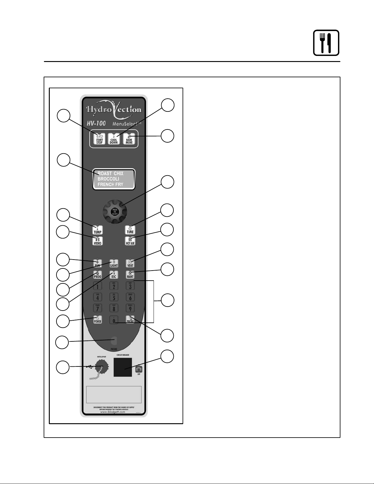
MenuSelectt Control
CONTROL DESCRIPTION
2
1
3
4
5
6
8
7
9
12
15
16
18
21
1. START/STOP KEY Ć press to start, cancel or
pause the bake
2. COOL DOWN KEY Ć initiates oven cool down
cycle
3. BAKE MORE KEY Ć press at the end of a bake
cycle to add additional bake time in one minĆ
ute increments.
4. DISPLAY Ć displays time or temperature and
other information related to oven function and/
or programming.
5. DIAL Ć used to enter set points, time, and proĆ
grammable settings. Also used to select the
programmed product.
6. TEMP KEY Ć used to set or change the bake
temperature
7. TIME KEY Ć used to set or change the bake
time.
8. HYDRO KEY Ć press to enter hydro mode
9. HOT AIR KEY Ć press to enter hot air mode
10. FAN KEY Ć press to select the fan speed
11. LIGHT KEY Ć press to turn the lights on and off.
12. VENT KEY Ć press to manually open and close
the oven vent
13. PROGRAM KEY Ć press to enter product proĆ
gramming and save programmed settings.
14. ESCAPE KEY Ć press to back up one step durĆ
ing programming
15. MAINTENANCE KEY Ć press to enter managĆ
er programming and save programmed setĆ
tings
16. ALPHA/NUMERIC KEYPAD Ć used to proĆ
gram recipes.
17. POWER KEY Ć used to place control in and out
of standby mode.
18. PROBE KEY Ć press to use core probe cookĆ
ing
19. CORE PROBE CONNECTION Ć plug core
temperature probe in here when using probe
cooking
20. USB Port and COVER - Use to transfer
recipes and data to/from the control
21. CIRCUIT BREAKER - Used to turn power to
the unit on or off.
Figure 9
17

Operation
MenuSelectt Control
OVEN STARTUP
1. Be sure the shutoff switch and/or circuit
breaker switch below the control panel are in
the on position. The display flashes OFF
PRESS POWER KEY TO START.
NOTE: If the real time clock and auto wake up
functions are enabled the display
reads PRESS POWER KEY TO START
AUTO START.
2. Press the POWER KEY (17). The display reads
PREHEAT and the oven heats to the last manuĆ
al set temperature in the hot air mode. The disĆ
play flashes READY / IDLE and the alarm beeps
5 times when the oven is at temperature and
ready to bake.
MANUAL COOKING
1. Turn the DIAL (5) until the display reads
MANUAL.
2. Press the TIME KEY (7). Rotate the dial, or use
the alpha/numeric keypad to enter the desired
bake time. Press the center of the dial to set
the bake time.
NOTE: Time is set in one minute increments
using the dial. To set time in less than
one minute increments use the alpha/
numeric keypad.
3. Press the TEMP KEY (6). Rotate the dial, or
use the alpha/numeric keypad to enter the deĆ
sired bake temperature. Press the center of
the dial to set the bake temperature. The oven
preheats to the new temperature.
NOTE: Temperature is set in 5 degree increĆ
ments using the dial. To set time in less
than 5 degree increments use the alĆ
pha/numeric keypad.
4. Press the desired mode key, Hydro or Hot Air.
If Hydro is selected, rotate the dial, or use the
alpha/numeric keypad to enter the desired
percentage of moisture.
5. When the display flashes READY / IDLE, open
the doors. Load the product.
6. Press the START/STOP KEY (1) to begin the
bake cycle. The timer counts down and the
display alternates between the cooking mode
and the name of the product.
PROGRAMMED COOKING
1. Turn the DIAL (1) until the name of the product
is highlighted. Press the center of the dial to
select. The oven preheats to the programmed
temperature in the correct cooking mode. The
display flashes READY / IDLE and the alarm
beeps 5 times when the oven is at temperaĆ
ture and ready to bake.
2. Open the doors. Load the product.
3. Press the START/STOP KEY (1) to begin the
bake cycle. The timer counts down and the
display alternates between the cooking mode
and the name of the product.
PROBE COOKING
1. Press the PROBE key (18) to select the probe
mode. The display reads CORE PROBE
COOK & HOLD. Turn the dial to select either
YES or NO. Press the center of the dial to seĆ
lect.
If YES is selected, Cook & Hold has been enĆ
abled. In the Cook & Hold mode, the oven cavĆ
ity lowers to the product pull temperature as
the product cooks.
If NO is selected, Cook & Hold has not been
enabled the cavity maintains the cook temperĆ
ature.
2. Turn the DIAL to enter the desired product pull
temperature in the display. Press the center of
the dial to save the pull temperature.
3. Press the TEMP KEY (6). Rotate the dial, or
use the alpha/numeric keypad to enter the deĆ
sired bake temperature. Press the center of
the dial to set the bake temperature. The oven
preheats to the new temperature.
NOTE: Temperature is set in 5 degree increĆ
ments using the dial. To set time in less
than 5 degree increments use the alĆ
pha/numeric keypad.
18

Operation
MenuSelectt Control
4. Press the desired mode key, Hydro or Hot Air.
If Hydro is selected, rotate the dial, or use the
alpha/numeric keypad to enter the desired
percentage of moisture.
5. Insert the core probe into the product. Load
product into the oven and close the door. Be
sure that the terminal end of the core probe is
outside of the oven and clear of the door.
6. Connect the core probe to the PROBE CONĆ
NECTION (19) at the bottom of the control.
NOTE: Do not connect the probe before the
cook mode has been selected.
7. The display gives the actual core probe temĆ
perature as well as the oven set temperature.
8. When the product reaches the pull temperaĆ
ture the buzzer sounds.
9. Press the START/STOP KEY (1) to silence the
buzzer.
If using Cook & Hold - The cavity temperaĆ
ture continues to drop to the product pull temĆ
perature and the display counts up, telling the
operator how long the product has been held.
Disconnect the core probe and remove the
product when ready.
If not using Cook & Hold - The cavity reĆ
mains at the cook temperature. The display
does not count up. Disconnect the core probe
and remove the product when the buzzer
sounds.
AT THE END OF ANY COOK CYCLE
1. An alarm sounds, the display reads DONE.
2. If more bake time is desired, press the BAKE
MORE KEY (3). This will add an additional one
minute of time for each press of the key.
3. When you are satisfied with the bake, press
the START/STOP KEY (1) to silence the alarm.
Open the door to remove the product.
OVEN SHUTDOWN
1. Press the COOL DOWN KEY (2). The display
reads AUTO COOL DOWN ACTUAL TEMP. To
speed up the cool down process, open the
doors and press the VENT KEY (12) to open
the vent.
2. When the oven has cooled down, the display
reads OFF PRESS POWER KEY TO START.
NOTE: The lights shut off and the vent closes
automatically at the end of the cool
down cycle.
DURING ANY COOK CYCLE
Venting Moisture from the Oven Cavity
1. Press the VENT KEY (12). This manually
opens the vent until the key is pressed again
to close it.
Pause a Bake Cycle
1. To pause a cook cycle, press the START/
STOP KEY (1). The LED on the start/stop key
flashes. The bake cycle will pause until the key
is pressed again.
Cancel a Cook Cycle
1. To cancel the cook cycle, press and hold the
START/STOP KEY (1).
19

Operation
MenuSelectt Control
PRODUCT PROGRAMMING
Entering the Program Mode
1. Press the PROGRAM KEY (13). If the control
is password protected, the display reads ENĆ
TER CODE. Use the alpha/numeric keypad to
enter the manager passcode 3124, then press
the center of the dial to enter the program
mode.
Naming a Product Recipe
NOTE: Use the following procedure to name a
new product or edit the name of an existing
product.
1. For a new recipe, turn the dial to the first open
product. Press the center of the dial to select.
To edit an existing name, rotate the dial to the
name to be changed. Press the center of the
dial to select.
2. Use the dial to scroll down to Edit Name. Press
the center of the dial to enter the edit name
menu.
3. Turn the dial or use the alpha/numeric keypad
to select the first character. Press the center of
the dial to advance to the next character. ReĆ
peat for all remaining characters.
NOTE: Product names may be up to 10 charĆ
acters long and can contain spaces.
Use the #1 key to insert spaces in a
recipe name.
NOTE: To select letters using the keypad,
press the appropriate key once if you
need the first letter on the key, twice for
the second and three times for the
third. For example to enter the letter L
press the #5 key three times.
4. Press the PROG KEY (13). With SAVE highĆ
lighted, press the dial to save the product
name.
Programming a Product Recipe
NOTE: The control can hold 99 recipes. Each recĆ
ipe may have up to 6 cooking stages.
1. Turn the dial to highlight the name of the prodĆ
uct to be programmed. Press the center of the
dial to select the product.
2. The display reads PRODUCT NAME: STAGE 1.
Press the center of the dial to select the stage.
3. Rotate the dial, or use the alpha/numeric keyĆ
pad to enter the desired bake time. Press the
center of the dial to set the bake time.
NOTE: Time is set in one minute increments
using the dial. To set time in less than
one minute increments use the alpha/
numeric keypad.
4. Rotate the dial to select the desired cooking
mode. Choose from Hydro or Hot Air. Press
the center of the dial to set the cook mode.
If Hydro is selected, rotate the dial, or use the
alpha/numeric keypad to enter the desired
percentage of moisture.
5. Rotate the dial, or use the alpha/numeric keyĆ
pad to enter the desired cook temperature.
Press the center of the dial to set the bake temĆ
perature.
NOTE: Temperature is set in 5 degree increĆ
ments using the dial. To set time in less
than 5 degree increments use the alĆ
pha/numeric keypad.
6. Rotate the dial to select the desired fan speed.
Choose from gentle, low, high or turbo. Press
the center of the dial to set the fan speed.
20

Operation
MenuSelectt Control
7. Rotate the dial to select the fan rotation cycle.
Choose between manual or auto.
NOTE: This is the length of time the fan will roĆ
tate in one direction before reversing.
If manual is selected, rotate the dial or use the
alpha/numeric keypad to enter the desired fan
cycle. Press the dial to set the fan cycle.
If auto is selected, the program will use the deĆ
fault fan cycle setting. The default is set
through the Manager Programming. See
page 22.
8. Rotate the dial to set the vent position. Choose
between OPEN or CLOSE. Press the center of
the dial to set the vent position.
9. Use the dial to scroll down to PRODUCT
NAME: STAGE 2. Press the center of the dial to
select stage 2.
10. Repeat steps 2Ć9 for all remaining stages.
11. When all stages have been programmed,
press the PROGRAM KEY (13). To save the
programming, use the dial to scroll to YES.
Press the center of the dial. The control exits
the program mode.
USING THE USB PORT
1. With the power on, remove the cover of the
USB port (20) and insert the USB drive.
2. Press the MAINTENANCE KEY (15).
3. Turn the dial to highlight MANAGER PROĆ
GRAM. Press the center of the dial to select.
4. Turn the dial to highlight either COPY RECIPE
FROM USB or COPY RECIPE TO USB, then
press the center of the dial to select.
5. When the transfer is complete, press any key
to return to the menu.
6. Turn the dial to highlight EXIT. Press the center
of the dial to select. The display returns to the
previous menu.
7. Turn the dial to highlight EXIT. Press the center
of the dial to select.
21

Operation
MenuSelectt Control
MANAGER PROGRAMMING
Entering the Manager Program Mode
1. Press the MAINTENANCE KEY (15). If the conĆ
trol is password protected, the display reads
ENTER CODE. Use the alpha/numeric keypad
to enter the manager passcode 3124, then
press the center of the dial to enter the proĆ
gram mode.
2. Turn the dial to highlight OVEN SETUP. Press
the center of the dial to select the product.
Programming Auto Start
NOTE: The Auto Start function enables the oven to
turn on at a programmed time of day and
preheat to a programmed temperature.
1. Turn the dial to highlight AUTO START. Press
the center of the dial to select.
2. Turn the dial to select either ON or OFF. Press
the center of the dial to select.
If ON is selected, the display reads AUTO
START 24 HOUR TIME 00:00. Turn the dial to
enter the time you would like the oven to begin
preheating. Press the center of the dial to seĆ
lect.
The display reads AUTO START TEMP XXX.
Turn the dial to enter the desired preheat temĆ
perature. Press the center of the dial to select.
Programming Oven Setup
These menus allow the manager to set up basic
oven functions
1. Turn the dial to highlight OVEN SETUP. Press
the center of the dial to select.
2. Turn the dial to highlight MANAGER PROĆ
GRAM. Press the center of the dial to select.
3. Turn the dial to highlight the oven function you
wish to change. Press the center of the dial to
select. Choose from the following functions:
Recipe Password - Select YES or NO to enĆ
able password protection on recipe programĆ
ming. If YES is selected the passcode 3124
must be entered to change recipe programĆ
ming.
Temp Unit - Select either degrees F or C.
Cool Down Temp - Select the set temperaĆ
ture for the oven to achieve in Cool Down
mode
Temp Disp Rate - Set the rate, in seconds,
at which the display switches between actual
and setpoint temperature
Input Rsp Time - Set the length of time alĆ
lowed to input each variable when programĆ
ming recipes before control automatically exĆ
its out
Setback Time - When not used for a period
of time, the oven temperature will automaticalĆ
ly reduce to conserve energy. This variable
sets the length of time the oven remains at the
idle temperature before being lowered.
Ready Beep - Select either ON or OFF. This
is the audible alarm that sounds when the
oven has reached the set temperature.
Cook Cool Fan - Select either YES or NO.
This function allows the control to display
OPEN OVEN DOOR when you are attempting
to lower the set temperature of the oven.
Restore Manual - Select either YES or NO.
This variable enables the oven to remember
the last settings used for manual cooking.
4. After editing a function, press the center of the
dial to save.
5. When all desired functions have been edited,
turn the dial to highlight EXIT. Press the center
of the dial to exit the manager programming
mode.
22

MANUAL MODE COOKING
1. Select the POWER button to turn on the oven
and proceed to the mode screen.
Operation
Touchscreen Control
2. Select MANUAL to cook using basic time and
temperature controls.
Figure 10
Figure 11
23

Operation
Touchscreen Control
3. Set the desired cooking parameters.
Temperature - Press the temperature text
and enter the desired oven temperature on
the keypad provided. Press SAVE and EXIT to
return to this screen.
Cook Time - Press the time text and enter the
desired bake time on the keypad provided.
Press SAVE and EXIT to return to this screen.
Core Probe Cooking - To use the probe
cooking feature, insert a product probe in the
probe outlet on the control panel. Press the
PROBE COOK icon. Press the temperature
text that appears and enter the desired prodĆ
uct core temperature on the keypad provided.
Press SAVE and EXIT to return to this screen.
Cavity Moisture - Press the HOT AIR icon to
reduce the cavity moisture content in 10% inĆ
crements. At 0% the oven is in the Hot Air
mode. Press the HYDRO icon to increase the
cavity moisture content in 10% increments. At
100% the oven is in the Hydro mode.
Temperature
Fan Speed - With the FAN icon highlighted,
press the fan speed text (75% in Figure 12) to
increase the fan speed in 25% increments.
When 100% is displayed, press the text again
to reduce the fans speed to 25%.
Fan Reversal Interval - To adjust the fan reĆ
versal time, press the FAN icon. Then press
the time text and enter the desired reversal inĆ
terval on the keypad provided. Press SAVE
and EXIT to return to this screen.
Vent Position - At any time the vent can be
opened or closed by toggling the VENT icon.
When the icon is highlighted the vent is open.
Lights - At any time the lights can be turned
on or off by toggling the LIGHT icon.
4. Press START Icon to begin cooking. Press
Cancel to stop cooking. Press +1 MIN to add
1 minute to the cook time.
Time
Hot Air Mode
Fan Speed
Lights
Probe cooking
Hydro Mode
Fan Reversal
Increment
Vent position
Figure 12
24

Operation
Touchscreen Control
MENU MODE COOKING
1. Select the MENU icon to cook using the pre
programmed menu items.
2. Select the desired food category for your
product.
Figure 13
Figure 14
25

Operation
Touchscreen Control
3. Within the food category, select the desired
product you wish to cook.
4. Select which shelves you intend to place the
food on. Press the ADD ITEM icon to return to
step #2 and add different items that share the
same set point parameters but may have difĆ
ferent cook times.
When the START HEATUP icon is pressed, the
oven will automatically heat up to the product
set temperature.
Once preheated, the START HEATUP icon will
change to START. At this point, load the prodĆ
uct, close the doors, and press START.
Figure 15
Figure 16
26

Operation
Touchscreen Control
5. During the cook cycle, individual shelf cook
timers will count down as the product is
cooked. If you wish to cancel the bake, you
can press the ESC button at any time.
Once the bake is complete the beeper will
sound and the ADD 1 MINUTE icon will appear
next to each complete product.
EDITING A MENU
1. Select the MENU/EDIT icon to edit the recipes
in the menu mode.
Figure 17
Figure 18
27

Operation
Touchscreen Control
2. Select the EDIT ITEMS icon to edit the menu
items.
To delete an Item, select the item while the DEĆ
LETE key is highlighted.
To create a new item, select the NEW ? icon
while the EDIT key is highlighted.
Figure 19
3. Select which mode you would like to be in,
Edit or Delete.
To edit an existing item, select the item while
the EDIT key is highlighted.
Figure 20
28

Operation
Touchscreen Control
4. Each recipe is made up of steps. A new step
is needed each time a parameter within a
stage changes.
To edit a parameter within a particular step,
press the text of that parameter. A keypad will
appear for you to input your desired value for
that parameter.
To add a step, press the ADD STEP icon on the
lower left of the screen.
To delete a step, use the arrows in the lower
left corner of the screen to highlight the step
you wish to delete. Press DELETE STEP to deĆ
lete the highlighted step.
Once you are finished, press SAVE and EXIT
to confirm your changes and return to the preĆ
vious screen.
EDITING A CATEGORY
1. Select the MENU/EDIT icon to edit the recipes
in the menu mode.
Figure 21
Figure 22
29

Operation
Touchscreen Control
2. Select the EDIT CATEGORIES icon to select
which items are in each category.
3. Select what you would like to edit about the
category.
To edit the name, press the EDIT NAME icon.
A keyboard will appear, enter the desired
name and press SAVE and EXIT to return to
this menu.
To edit the category icon, press EDIT ICON
and go to step #5.
To edit the items contained within a category,
press SELECT ITEMS and go to step #4.
If you are done, Press SAVE and EXIT to return
to the previous screen.
Figure 23
Figure 24
30

Operation
Touchscreen Control
4. Select which items you would like to appear
under the category. When complete, press
ESC to save and return to the previous menu.
5. After pressing EDIT ICON in step #3, the folĆ
lowing screen will appear. Select the desired
icon or press the arrow icon to view more icon
options. Once you select an icon, you will be
sent back to Step #3.
Figure 25
Figure 26
31

Operation
Touchscreen Control
COOL DOWN
1. To cool down the unit, press the COOL DOWN
icon.
2. The oven will display COOLING in yellow until
the oven is cool. Once cool, the oven will go to
standby.
Figure 27
Figure 28
32

Maintenance
Spray Bottle Operating Procedure
NOTE: Only use a commercial oven cleaner/deĆ
greaser with the spray bottle. DO NOT use
chemicals that are not intended as oven
cleaners. See chemical manufacturer's inĆ
formation for intended use.
1. Unscrewāā ātheā āāsprayerāāā āhead āāāāandāāā āfillā āāāthe containĆ
er to the MAX mark. Screw the head assembly
āon āfirmlyā toā āensureā āan āāairtight seal. The liquid
must be clean and free from foreign matter. Do
not overfill Ć space must be left for compressĆ
ing air.
2. To build up pressure, pump approximately 20
full strokes when the container is filled with liqĆ
uid. The higher the pressure, the finer the
spray. If the container is only partially filled,ā
then āmoreā pumping āāis āārequired āto compress
the additional air space.
3. To spray, depress the trigger with your thumb.
4. Adjust spray nozzle for a wide spray pattern.
5. After a period of spraying, the pressure will
drop. Restore the pressure by operating the
air pump.
6. Release pressure after use by inverting the
spray head and depressing the trigger or byā
slowly āunscrewing ā theā spray āhead assembly
āwhichā willā allow āairā toā escape āfrom around āāāthe
filling aperture.
7. Afterā use,ā rinse āthe āsprayā bottleā withā clean waĆ
ter and check that the hole in the nozzle is āperĆ
fectly āclean āand clear. Warm water (notā hot)ā
usedā withā aā household ādetergent is a useful
cleaning agent for this purpose.
NOTE: Further information can be found in the inĆ
struction leaflet supplied with your spray
bottle.
WARNING!!
Protective clothing and eyewear should
be worn while using cleaning agents.
Spray
Head
Pressure
Vessel
Clean the pump 2 or 3 times per week with warm water
Pressure Pump
Pump
MAX
Spray Trigger
Figure 29
Complete Spray Bottle - P/N R0006
Spray Head Repair Kit - P/N R6332
33

Maintenance
Cleaning and Preventive Maintenance
CLEANING THE INTERIOR
Daily Cleaning
Daily cleaning of the appliance is essential for sanitaĆ
tion, and to ensure against operational difficulties.
The stainless steel cavity may corrode with improper
cleaning of the oven. Use an oven cleaning deterĆ
gent in conjunction with the supplied spray bottle.
For difficult cleaning, allow the sprayĆon oven
cleaner to work longer before rinsing.
1. Cool āāthe āappliance down to 140_F (60_C) or,
if the āāovenāā has āābeenā āidle, āāturnā the Hydro modeā
onā foār 3 āto ā4ā minutesā inā order āāāto warm the cavĆ
ity surfaces.
2. Fill āāāāātheāāā āsprayāāā ābottleā āāandāāā pump āāāairā āāintoāā āthe conĆ
tainer with the pressure pump.
3. Spray āāthe āinteriorā of āātheāā ovenā with a cleaning
solution. Be certain to spray cleaner through
the fan guard to cover all surfaces.
NOTE: Never spray water into the appliance
when the temperature is above 212_F
(100_C).
4. Let āthe ācleanerā āworkāā the time recommended by
the cleaning solution manufacturer. āForā āādifficult,
baked on grease, etc. allow to work over night.
5. Set the timer for 15 to 20 minutes.
6. Run āātheā āoven at 225_F (107_C) in the Hydro
mode with 100% humidity. This will soften all
burned on residue.
7. Rinseāā āātheāāā āapplianceāāāāā interiorā āāāwithāāāāā waterāā (a hose
is supplied,āā ābut āāātakeāā careā thatā only āātheā interior
cavity is sprayed with water). Wipe the interior
dry after rinsing.
8. The door should be kept slightly open after
cleaning. This will allow the oven to vent and
increase the life of the door gasket.
On stainless interiors, deposits of baked on splatĆ
ter, oil, grease or light discoloration āmay ābe āreĆ
moved āwith āa good non toxic industrial stainless
steel cleaner. Apply cleaners when the oven is
cold and always rub with the grain of the metal.
The racks, rack supports and the blower wheel
may be cleaned in the oven or by removing them
from the āoven āand āsoaking āthem in a solution of
ammonia and water.
NOTE: DO NOT use corrosive cleaners not inĆ
tended for oven cleaning on your HyĆ
drovection oven.
Recommended cleaners:
a.) ECOLAB Greasecutter Plus
b.) CELLO EZ Clean
c.) DiverseyĆLever Advance Oven Cleaner
WARNING!!
Be sure to read and follow the MSDS or
safety instructions on the bottle for your
oven cleaner.
34

Maintenance
Cleaning and Preventive Maintenance
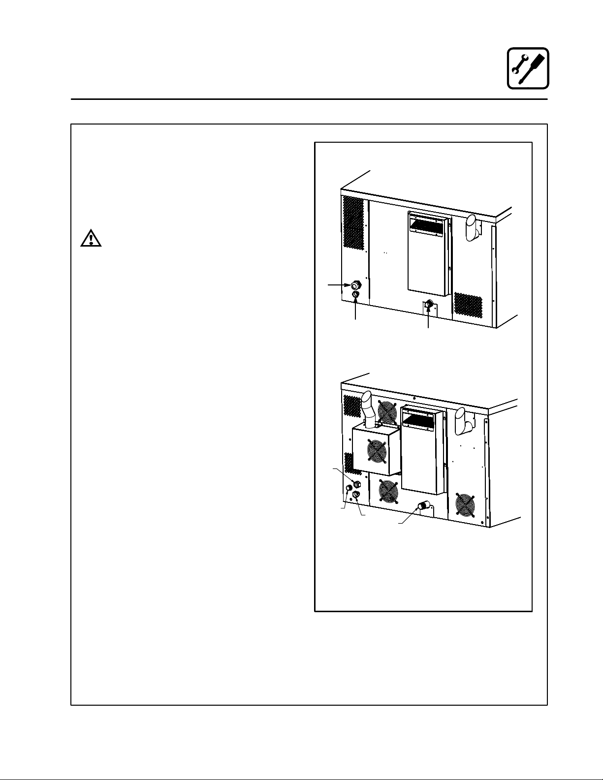
Oven Weekly Cleaning
In addition to the daily cleaning, it is necessasry to
clean behind the fan guard of this oven on a weekĆ
ly basis. This is necessary for proper functioning
of the oven. Scale will build up on the fan and heat
source leading to a less efficient oven.
1. Turn off the oven. Make sure that the oven is
cooled down to under 140_F (60_C).
2. Remove the rack guides.
3. Rotate the two screws on the left side of the fan
guard.
Figure 30
4. Remove the fan guard.
5. Thoroughly spray cleaner onto the fan and
heat source. Close the door to allow the cleanĆ
er to work.
6. After ten minutes, rinse the cleaner off. Return
the fan guard to the closed position. Rotate
the two screws to secure the fan guard.
Remove and clean the blower wheel every 6
months.
CLEANING THE EXTERIOR
The exterior of the appliance may be cleaned and
kept in good condition with a light oil. Saturate a
cloth and wipe the appliance when it is cold; wipe
dry with a clean cloth.
WARNING!!
DO NOT spray the outside of the appliance
with water or clean with a water jet. CleanĆ
ing with a water jet can impregnate chloĆ
rides into the stainless steel, causing the
onset of corrosion.
PREVENTIVE MAINTENANCE
The best preventive maintenance measures are
āāāthe āāāproper āāinitial āāinstallation āāof āāthe equipment and
a program for cleaning the appliance routinely.
The Hydrovection requires no lubrication. Contact
the factory, the factory representative or a local
Blodgett service company to perform mainteĆ
nance and repairs should they be required.
Figure 31
35

Introduction
Description du four et Spécifications
Les fours Hydrovection de Blodgett sont des apĆ
pareils haut de gamme fabriqués en acier inoxyĆ
dable de première qualité en faisant appel à des
procédés supérieurs.
Le ventilateur à deux vitesses est doté d'un dispoĆ
sitif de protection pour les doigts et alimenté par
un puissant moteur silencieux. Le condenseur asĆ
pire l'excès de vapeur de l'appareil. La condensaĆ
tion et les eaux usées sont continuellement évaĆ
cuées.
L'isolant de haute qualité empêche un rayonneĆ
ment thermique excessif et aide à conserver
l'énergie.
En option, des pieds réglables et des supports
permettent d'adapter le four aux surfaces inégales
et à tous les modèles de table.
Les portes pratique du four est dotée d'un hublot
et possède un grand rayon d'ouverture. La poiĆ
SPÉCIFICATIONS DE PLOMBERI
EAU
Pression d'eau 30 lb/po2 (207 kPa) minimum
50 lb/po2 (345 kPa) maximum
gnée de la porte est facile à saisir, même avec des
mains mouillées ou grasses.
La disposition simple des commandes facilite l'utiliĆ
sation de l'appareil. Même un cuisinier inexpérimenĆ
té peut facilement utiliser l'appareil grâce à un systèĆ
me de pictogrammes explicites. La troisième
fonction du sélecteur, le mode Cool Down (refroidisĆ
sement), permet de refroidir rapidement la cavité du
four lorsque la porte est ouverte.
L'appareil exige un nettoyage minime. L'intérieur
est vaporisé d'une solution nettoyante à action inĆ
stantanée qui réagit avec avec l'humidité pour éliĆ
miner les croûtes et les taches. La conception du
fourĆétuveur Combi assure un entretien facile. Les
soudures sont étanches à l'eau, ce qui permet de
rincer la cavité du four après le nettoyage à la vaĆ
peur.
Raccordement d'eau Boyau d'eau froide 3/4 po
Réglage du régulateur
d'eau
Conditions requises
minimum
DRAINAGE
Type de drain Drain de mise à l'air libre
Raccordement du drain 1" NPT Mâle
Température moyenne
de l'eau au drainage
Prérégler à 30 lb/po2 (207 kPa)
Total des solides en suspension (TDS) - doit être moins que
100 parties par million
Dureté totale de l'eau - 80Ć120 parties par million
Chlorides - doit être moins que 30 parties par million
Chlorine - 0 parties par million
Le pH de l'eau - 7.0Ć8.0
Environ 60_C (140_F)
36

Introduction
Description du four et Spécifications
CARACTÉRISTIQUES TECHNIQUES - HVĆ100G
Type de
gaz
Naturel 60 000 BTU/h 120 1 20 1/2 HP 208Ć240 V c.a., 3 fase,
Propane 60 000 BTU/h 120 1 20 1/2 HP 208Ć240 V c.a., 3 fase,
Connecteur de 3/4 po FNPT pour toutes les installations canadiennes et américaines
Entrée Tension Phase Intensité Moteur
50/60 Hz
50/60 Hz
CARACTÉRISTIQUES TECHNIQUES - HVĆ100E
Tension Fréquence kW Phase
208 60 15 3 38 38 38 1/2 HP 208Ć240 V c.a., 50/60 Hz
240 60 15 3 36 34 34 1/2 HP 208Ć240 V c.a., 50/60 Hz
440 60 15 3 20 18 18 1/2 HP 208Ć240 V c.a., 50/60 Hz
480 60 15 3 18 17 17 1/2 HP 208Ć240 V c.a., 50/60 Hz
208 60 13 3 33 33 36 1/2 HP 208Ć240 V c.a., 50/60 Hz
Charge maximale
(ampères)
L1 L2 L3
Moteur
240 60 13 3 31 29 29 1/2 HP 208Ć240 V c.a., 50/60 Hz
440 60 13 3 16 16 17 1/2 HP 208Ć240 V c.a., 50/60 Hz
480 60 13 3 15 15 16 1/2 HP 208Ć240 V c.a., 50/60 Hz
37

Installation
Certifications
LES PRÉSENTES CONSIGNES D'INSTALLATION
SONT DESTINÉES AU PERSONNEL D'INSTALĆ
LATION ET D'ENTRETIEN QUALIFIÉ SEULEĆ
MENT. TOUTE INSTALLATION OU TOUT ENTREĆ
TIEN EFFECTUÉ PAR DES PERSONNES NON
COMPÉTENTES POURRAIENT ENDOMMAGER
LE FOUR OU CAUSER DES BLESSURES.
Le terme personnel d'installation qualifié désigne
une personne, une entreprise, une société ou une
organisation assumant, elleĆmême ou par l'entreĆ
mise d'un représentant, les responsabilités suiĆ
vantes :
D la pose ou le remplacement des tuyaux de gaz.
Le raccordement, la mise en service, la réparaĆ
tion ou l'entretien du matériel.
D La pose du câblage électrique à partir du compĆ
teur, de la boîte de distribution principale ou de
la prise jusqu'à l'appareil.
Le personnel qualifié doit détenir de l'expérience
dans ces domaines, connaître toutes les mesures
de sécurité pertinentes et respecter les normes de
la province ou des autorités locales.
Mises en service américaines et canadiennes
La mise en service doit respecter les normes locaĆ
les ou, en l'absence de tels normes, les règleĆ
ments suivants : National Fuel Gas Code,
NFPA54/ANSI Z223.1 - dernière édition, le Code
d'installation du gaz naturel CAN/CGAĆB149.1 ou
le Code d'installation du propane, CAN/CGAĆ
B149.2, selon le cas.
Référence : National Electrical Code, ANSI/NFPA
70 - dernière édition ou le Code canadien de
l'électricité CSA C22.1, selon le cas.
La mise en service de ce matériel doit respecter
les normes suivantes : Basic Plumbing Code of the
Building Officials and Code Administrators InterĆ
national Inc. (BOCA) et Food Service Sanitation
Manual du Food and Drug Administration (FDA).
L'appariel doit etre installe avec l'empechement
de refoulement selon les codes federale,
provincial et locaux.
Mise en service dans les autres pays
L'installation doit respecter les normes nationales
et locales, qui varient selon le pays. Si vous avez
des questions sur les méthodes d'installation acĆ
ceptables ou sur le fonctionnement de votre appaĆ
reil, veuillez communiquer avec votre détaillant.
S'il n'y a aucun détaillant dans votre région, veuilĆ
lez communiquer avec Blodgett au
0011Ć802Ć658Ć6600.
38

Installation
Emplacement du four et mise de niveau et Ventilation
RESPONSABILITÉS DU PROPRIÉTAIRE
Responsabilités de l'installation avant l'inspecĆ
tion de mise en service
Vous avez droit à une inspection de mise en serviĆ
ce gratuite effectuée dès que possible par notre
représentant. Avant que cette personne se préĆ
sente pour effectuer la mise en service, vous deĆ
vez vous assurer de satisfaire déjà aux exigences
suivantes :
1. Le four est déballé, empilé (s'il y a lieu) et mis
en place.
REMARQUE:Veuillez consulter la section MontaĆ
ge des pieds et Superposition.
Charges maximales sure une tablette - 27.3 kg
(60lb)
EMPLACEMENT DU FOUR
Il est important de bien choisir l'emplacement de voĆ
tre four afin d'en augmenter les performances et
l'utilité.
Vous devez conserver un dégagement minimal enĆ
tre le four et toute construction combustible ou non
combustible. Consultez le tableau ciĆdessous.
De plus, il est recommandé de respecter les dégaĆ
gements suivants pour l'entretien.
D Parois latérales du four - 30 cm (12 po)
D Paroi arrière du four - 30 cm (12 po)
DÉGAGEMENT ACCEPTABLE
Modèle
du four
HVĆ100E 0 mm
HVĆ100G 0 mm
VENTILATION
On ne saurait trop insister sur la nécessité de préĆ
voir un système d'aération bien conçu. Un tel
système permettra au four de bien fonctionner,
Côté
droit
(0 po)
(0 po)
Côté
gauche
0 mm
(0 po)
0 mm
(0 po)
Arrière
152,4 mm
(6 po)
152,4 mm
(6 po)
tout en évacuant les vapeurs et produits de comĆ
bustion gênants de la zone d'utilisation.
L'extraction des fumées de combustion de l'appareil
doit se faire au moyen d'un groupe d'aspiration à
commande mécanique. CeluiĆci doit être dimenĆ
sionné de façon à ce qu'il recouvre entièrement l'apĆ
pareil, tout en dépassant d'au moins 15 cm de tous
les côtés qui ne sont pas contigüs à un mur. Le
groupe doit avoir la capacité qui convient et un apĆ
point d'air adéquat doit être prévu.
AVERTISSEMENT!!
Une mauvaise extraction des fumées de
combustion du four peut mettre en danĆ
ger la santé de l'opérateur. Elle aura
également pour résultats des problèmes
de fonctionnement, une cuisson laissant
à désirer et de possibles dégâts subis par
le matériel. Les dégâts résultant directeĆ
ment d'une aération inadéquate ne seront
pas couverts par la garantie offerte par le
fabricant.
Si cet appareil est installé dans le Commonwealth
du Massachusetts, il doit s'emboîter avec le
système de sortie de la hotte, de sorte que l'appaĆ
reil puisse fonctionner seulement quand le
système de sortie de la hotte est en marche.
Mises en service américaines et canadiennes
Se reporter aux codes locaux de la ventilation. En
l'absence de codes locaux, se reporter au code
national de la ventilation intitulé Normes pour
l'installation d'équipements pour l'enlèvement des
fumées et vapeurs grasses provenant d'équipeĆ
ments commerciaux pour la cuisine", NFPA-96Édition la plus récente.
Mise en service dans les autres pays
L'installation doit respecter les normes nationales
et locales, qui varient selon le pays. Si vous avez
des questions sur les méthodes d'installation acĆ
ceptables ou sur le fonctionnement de votre appaĆ
reil, veuillez communiquer avec votre détaillant.
S'il n'y a aucun détaillant dans votre région, veuilĆ
lez communiquer avec Blodgett Combi au
0011Ć802Ć860Ć3700.
39

Installation
Montage des pieds
OPTIONS
Pied réglable de 635 mm (25 po)
216mm (8Ć1/2 po) avec
Les Roulettes, Pieds réglable ou Pieds Séismiques
MONTAGE
1. Alignez le goujon fileté situé sur l'un des pieds
avant avec le trou de boulon situé au coin inféĆ
rieur de l'appareil. Tournez le pied dans le
sens horaire et serrez jusqu'au tour complet
le plus proche.
2. Alignez les trous de la plaque de montage du
pied avec les trous de boulon. Fixez solideĆ
ment au moyen des deux boulons de 1/2 po
fournis.
3. Répétez les étapes précédentes pour l'autre
pied avant. Si vous utilisez des roulettes, inĆ
stallez les roulettes à frein à l'avant du four. Les
roulettes arrière ne se bloquent pas. AssurezĆ
vous que les roulettes avant sont bloquées.
4. Penchez le four vers l'avant sur les pieds avant
que vous venez d'installer. Si vous venez d'inĆ
staller des roulettes, assurezĆvous que les rouĆ
lettes avant sont bien bloquées. Répétez les
étapes précédentes pour les pieds arrière.
5. Pour mettre le four de niveau (sauf pour les
modèles dotés de roulettes), vissez ou dévisĆ
sez les pieds réglables selon le cas.
Figure 32
Figure 33
40

Installation
Accessoire des roulettes
ROULETTES POUR FOUR SIMPLE
1. Placer les pieds comme décrit.
2. Desserrer l'écrou de blocage des embouts au
bas de chaque pied réglable. Retirer les embouts.
3. Insérer une roulette dans chaque pied, comĆ
me illustré. Serrer les écrous de blocage pour
fixer les roulettes.
Embouts de
pied ajustables
Ensemble de roulette
Figure 34
ROULETTES POUR DEUX FOURS SUPERPOĆ
SÉS
1. Placez un niveau sur le plancher où les rouletĆ
tes seront installées.
2. Placez des cales sous le côté bas jusqu'à ce
qu'il soit de niveau.
3. Montez les cales entre les roulettes et le four
comme suit :
a.) Alignez les cales et les trous des roulettes
avec les trous des boulons.
b.) Attachez avec les boulons de 13 mm (1/2
pouce) fournis.
REMARQUE:Il faut les installer avec les rouletĆ
tes bloquantes à l'avant du four.
Les roulettes arrière ne se verĆ
rouillent pas. AssurezĆvous que
les verrous des roulettes avant
sont enclenchés.
4. Basculez le four vers le haut sur les roulettes
nouvellement installées.
41
Ajoutez des
ales selon
les besoins
Plancher
Echelle surdimensionnée pour raison de clarté
Figure 35

Installation
Superposition
ATTENTION !!
Seul un installateur qualifié peut effectuer
la superposition des appareils. Les appaĆ
reils sont lourds. AssurezĆvous d'utiliser
des outils et des méthodes appropriés
pour soulever et superposer les appareils.
1. Posez les pieds ou les roulettes sur l'appareil
du bas. Consultez la page 40 ou 41.
2. Placez le four du haut sur le four du bas. AssuĆ
rezĆvous que les quatre côtés sont bien
alignés.
3. Boulonnez les deux fours ensemble par derĆ
rière utilisant les agrafes d'empilage.
les agrafes
d'empilage
les agrafes
d'empilage
Vue arrière HVĆ100E
42

les agrafes
d'empilage
Installation
les agrafes
d'empilage
Vue arrière HVĆ100E
Figure 36
43

Installation
RACCORDEMENT À L'EAU
REMARQUE:Doit employer l'EAU FROIDE SEULEĆ
MENT.
Raccordez l'appareil à une source d'eau propre
au moyen d'un boyau de pression muni de racĆ
cords de 19 mm GHT (3/4 po). Consultez la
Figure 37 pour le raccordement. Prévoyez l'instalĆ
lation d'un robinet d'arrêt à proximité du four.
ATTENTION !!
L'utilisation de l'appareil non équipé du
régulateur d'eau annule votre garantie.
Ce produit doit être installé par un plombier ou un
monteur d'installations au gaz accrédité, si installé
dans le Commonwealth du Massachusetts.
RACCORDEMENT DU DRAIN
Raccordement de la plomberie
HVĆ100E
A
C
D
Acheminez le drain jusqu`à un fossé de drainage
dans le plancher et évitez d'utiliser des boyaux qui
pourraient s'affaisser et entraîner des accumulaĆ
tions d'eau. Le client est responsable de fournir la
tuyauterie raccordant le four et le drain.
Raccordement à l'eau et à l'égout particulier à
la ville de Los Angeles
1. Chaque conduite de vidange raccordée à
l'appareil doit être acheminée sans déclivité
ou fléchissement pour se terminer auĆdessus
du niveau de tropĆplein d'un récipient d'eaux
usées indirectes homologué.
2. L'appareil doit être installé conformément aux
instructions imprimées du fabricant et aux édiĆ
tions de 1999 du LAPC et du LAMC.
3. Un dispositif de protection contre le retour
d'eau peut être exigé par les codes locaux.
Dans ce cas, installezĆle sur le système d'eau
potable, directement en amont de l'appareil.
Ce dispositif doit être l'un des suivants : un reniĆ
flard de type antiĆvide homologué installé à au
moins 12 po auĆdessus du point le plus élevé,
un disconnecteur à deux clapets de nonĆretour
ou un disconnecteur hydraulique principal à
pression réduite.
HVĆ100G
A
B
C
D
A = Connexion électrique
B = Connexion du gaz
C = Raccordement d'eau
l'eau filtrée est fortement recommandé
D = Raccordement du drain
Figure 37
44

Raccordement à l'électricité
Installation
Tous les modèles
REMARQUE:Seul un technicien qualifié peut effecĆ
tuer le raccordement à l'électricité.
Avant de procéder au raccordement à l'électricité
des appareils, assurezĆvous que la source d'aliĆ
mentation est conforme aux spécifications de tenĆ
sion, d'intensité et de phase indiquées sur la plaĆ
que signalétique de l'appareil.
Le disjoncteur raccordé à cet appareil doit être
doté de contacts espacés d'au moins 0,076 po (2
mm). Le disjoncteur doit respecter toutes les norĆ
mes d'installation nationales et locales.
L'installation de tous les appareils doit se conforĆ
mer aux codes d'électricité nationaux et locaux.
Le schéma de câblage se trouve à l'intérieur du
panneau latéral amovible.
REMARQUE:Débranchez la source d'alimentation
électrique de l'appareil avant de proĆ
céder à l'entretien.
ATTENTION !!
Une installation non conforme annule voĆ
tre garantie.
Modèles électriques
On doit acheminer le conduit de vidange jusqu'à
un drain d'évacuation de plancher ouvert. De
plus, il faut éviter d'utiliser en guise de conduit de
vidange un boyau flexible, qui peut s'affaisser et
y entraîner l'accumulation d'eau piégée. Il incomĆ
be au client de fournir la tubulure du four au drain.
Modèles à gaz
Installations canadiennes et américaines
Un cordon d'alimentation muni d'une fiche est
fourni avec l'appareil (modèles 115V seulement).
Branchez la fiche dans une prise de courant apĆ
propriée.
ATTENTION !!
Si le cordon d'alimentation est endommaĆ
gé, remplacezĆle par un cordon spécial
ou un dispositif fourni par le fabricant ou
par un réparateur reconnu.
45

Installation
gueur
du t
Raccordement au gaz
CONDUITE DE GAZ
Il est essentiel d'avoir un circuit d'alimentation en
gaz approprié afin que le four puisse donner un
rendement maximal. Les dimensions de la tuyauĆ
terie doivent permettre d'assurer une alimentation
en gaz suffisant pour satisfaire à la demande maxiĆ
male de tous les appareils en service, et ce sans
perte de pression.
Exemple :
REMARQUE:Les valeurs indiquées en BTU à titre
d'exemple s'appliquent au gaz naturel.
Supposons que vous achetiez un appareil BCXĆ14G
pour accroître votre capacité de cuisson.
1. Additionnez les puissances nominales en
BTU des appareils déjà en place.
Friteuse Pitco 120 000 BTU
Cuisinière à 6 éléments 60 000 BTU
Four à pont 50 000 BTU
Total 230 000 BTU
2. À ce total, ajoutez la puissance nominale en
BTU du nouveau four.
Total précédent 230 000 BTU
HVĆ100G 60 000 BTU
Nouveau total 290 000 BTU
3. Mesurez la distance du compteur de gaz
jusqu'aux appareils de cuisson pour obtenir la
longueur du tuyau. Supposons que la lonĆ
gueur de tuyau soit de 30 pi (9 m) et que le
tuyau possède un diamètre de 1 po (2,54 cm).
4. Utilisez la table de calcul appropriée pour déĆ
terminer la capacité totale de votre conduite
de gaz actuelle.
Dans cet exemple, la capacité totale est de 375
000 BTU. Puisque la pression totale de gaz néĆ
cessaire est de 290 000 BTU, donc inférieure à
375 000 BTU, il n'est pas nécessaire pour l'instant
d'augmenter la tuyauterie actuellement en place.
REMARQUE:Les capacités en BTU indiquées
dans ces tableaux sont valables pour
les tuyaux droits seulement. L'ajout
de coudes et de raccords courbés
diminue la capacité de la tuyauterie.
Par exemple, un raccord en L de noĆ
menclature 40 de 1Ć1/2 po possède
une capacité équivalente à un tuyau
droit de 4,2 po (10,2 cm). RenseigĆ
nezĆvous auprès de votre fournisseur
en gaz local si vous avez des quesĆ
tions à ce sujet.
Capacité maximale en gaz naturel d'une
tuyauterie en fer en pieds cubes à l'heure
(Chute de pression de 0,5 po de colonne d'eau)
LonĆ
gueur
du
tuyau
(pi)
10 360 680 1 400 2 100 3 950
20 250 465 950 1 460 2 750
30 200 375 770 1 180 2 200
40 170 320 660 990 1 900
50 151 285 580 900 1 680
60 138 260 530 810 1 520
70 125 240 490 750 1 400
80 118 220 460 690 1 300
90 110 205 430 650 1 220
100 103 195 400 620 1 150
Extrait du National Fuel Gas Code, partie 10, tableau 10Ć2
Capacité maximale de la conduite en milliers de
BTU/h de gaz PP non dilué à 11 po de colonne
(Chute de pression de 0,5 po de colonne d'eau)
Longueur
uyau
(pi)
10 608 1 146 3 525
20 418 788 2 423
30 336 632 1 946
40 287 541 1 665
50 255 480 1 476
60 231 435 1 337
70 215 404 1 241
80 198 372 1 144
90 187 351 1 079
100 175 330 1 014
Extrait du National Fuel Gas Code, partie 10, tableau 10Ć15
Dimensions nominales (po)
3/4po1 po 1 1/4po1 1/2po2 po
d'eau
Diamètre interne (po)
3/4 po 1 po 1 1/2 po
46

Raccordement au gaz
Installation
RÉGULATION DE LA PRESSION ET ESSAIS
Évaluez la pression d'alimentation du gaz pour
chaque appareil lorsque les brûleurs sont alluĆ
més. Il doit y avoir une pression suffisante à l'enĆ
trée pour répondre aux normes. Consultez le taĆ
bleau ciĆdessous pour connaître la pression de
gaz qui convient.
Chaque appareil est réglé en usine de manière à
fonctionner avec le type de gaz indiqué sur la plaĆ
que signalétique.
Chaque four est muni d'un détendeur qui mainĆ
tient le gaz à la bonne pression. Ce détendeur est
essentiel au bon fonctionnement du four et ne
doit jamais être débranché.
N'INSTALLEZ PAS UN DEUXIÈME DÉTENDEUR
AU POINT DE CONNEXION DU GAZ À MOINS
QUE LA PRESSION D'ALIMENTATION SOIT SUĆ
PÉRIEURE À 14 PO DE LA COLONNE D'EAU (1/2
LB/PO2) (37 mbars).
Pendant les essais de pression, débranchez le
four ainsi que son robinet d'arrêt de la tuyauterie
d'alimentation en gaz si la pression d'essai est suĆ
périeure à 1/2 lb/po2 (3,45 kPa).
Isolez le four de la tuyauterie d'alimentation en gaz
en fermant son robinet d'arrêt pendant les essais de
pression de la tuyauterie de gaz si la pression d'esĆ
sai est égale ou inférieure à 1/2 lb/po2 (3,45 kPa).
Avant de raccorder les tuyaux d'alimentation en gaz
de l'appareil, videz complètement les tuyaux de touĆ
tes particules métalliques et de tout déchet. Après
le branchement, inspectez l'appareil afin de vous
assurer que la pression de gaz est appropriée.
Installations américaines et canadiennes
L'installation doit respecter les normes locales ou,
en l'absence de telles normes, les règlements suiĆ
vants : National Fuel Gas Code, NFPA54/ANSI
Z223.1 - dernière édition, le Code d'installation du
gaz naturel CAN/CGAĆB149.1 ou le Code d'installaĆ
tion du propane, CAN/CGAĆB149.2, selon le cas.
Installation dans les autres pays
L'installation doit respecter les normes nationales
et locales. Les normes d'installation locales ou les
règlements peuvent varier. Si vous avez des quesĆ
tions concernant les méthodes d'installation acĆ
ceptables ou sur le fonctionnement de votre appaĆ
reil, veuillez communiquer avec votre détaillant
local. S'il n'y a aucun détaillant local dans votre réĆ
gion, veuillez communiquer avec Blodgett Combi
au 0011Ć802Ć860Ć3700.
PRESSION DE GAZ - HVĆ100G
Type de gaz Pression
d'alimentation
Naturel 7 po de colonne d'eau .085 po de diamètre 3.5 po de
Propane 14 po de colonne d'eau .063 po de diamètre 10 po de
47
Dimensions
de l'orifice au
niveau de la mer
Pression d'admission
colonne d'eau
colonne d'eau

Installation
Câble d'immobilisation du tuyau à gaz
Si l'appareil est monté sur des roulettes, utilisez un
connecteur flexible ordinaire dont le diamètre inĆ
terne est d'au moins 1,9 cm (3/4 po) ainsi qu'un
raccord rapide.
Un câble d'immobilisation doit être utilisé pour liĆ
miter le mouvement de l'appareil de manière à ce
que le connecteur flexible ne subisse aucune tenĆ
sion. Attachez le câble au bâti du four le plus près
possible du connecteur flexible. Le câble doit être
assez court pour empêcher toute tension sur le
connecteur. Lorsque le câble est pleinement étiré,
il devrait être facile d'installer le connecteur et de
le brancher à l'aide du raccord rapide.
Le câble (de fort calibre) doit être installé sans enĆ
dommager l'immeuble. N'UTILISEZ PAS la
conduite de gaz ou les câbles électriques pour anĆ
crer l'extrémité permanente du câble d'immobiliĆ
sation! Utilisez des boulons d'ancrage vissés
dans le béton ou dans un bloc de béton. Pour les
murs de bois, utilisez des vis d'ancrage robustes
dans les montants des murs.
ATTENTION !!
Si le câble est enlevé pour quelque raison
que ce soit, installezĆle de nouveau une
fois l'appareil remis en place.
Installations américaines et canadiennes
Le connecteur doit respecter la norme Standard
for Connectors for Movable Gas Appliances, ANSI
Z21.69 ou Connectors For Moveable Gas ApplianĆ
ces CAN/CGAĆ6.16 et le raccord rapide doit resĆ
pecter la Standard for QuickĆDisconnect Devices
for Use With Gas Fuel, ANSI Z21.41 ou Quick DisĆ
connect For Use With Gas Fuel CAN 1Ć6.9. PréĆ
voyez des mesures adéquates pour limiter le mouĆ
vement de l'appareil sans compter exclusivement
sur le connecteur et le raccord rapide ou sur la
conduite connexe.
Chaque appareil doit être muni d'un collecteur de
condensats. Consultez NFPA54/ANSI Z223.1 Ć
dernière édition (National Fuel Gas Code) pour
connaître les méthodes d'installation d'un collecĆ
teur de condensats.
Installation dans un autre pays
L'installation doit respecter les normes nationales
et locales. Les normes d'installation locales ou les
règlements peuvent varier. Si vous avez des quesĆ
tions concernant les méthodes d'installation acĆ
ceptables ou le fonctionnement de votre appareil,
veuillez communiquer avec votre détaillant local.
S'il n'y a aucun détaillant dans votre région, veuilĆ
lez communiquer avec Blodgett Combi au
0011Ć802Ć860Ć3700.
Plaque de fixation (fixez au
boulon de montage dupied)
Raccord rapide
Tuyau à gaz
Installation du tuyau à gaz et du câble d'immobilisation
Conduite d'alimentation
en gaz
Câble d'immobilisation
Figure 38
48
IMPORTANT : Attachez le câble
d'immobilisation le plus près possiĆ
ble du connecteur flexible et assuĆ
rezĆvous qu'il est assez court pour
éliminer toute tension sur le
connecteur.
Lorsque le câble est étiré au maxiĆ
mum, il devrait être facile d'installer
et de raccorder rapidement le
connecteur flexible.

Fonctionnement
Renseignements sur la sécurité des appareils au gaz
Les renseignements contenus dans la présente
section sont destinés au personnel d'exploitation
qualifié, c.ĆàĆd. les personnes qui ont soigneuseĆ
ment lu ce manuel et qui se sont familiarisées avec
les fonctions du four ou qui détiennent de l'expéĆ
rience dans le fonctionnement de l'appareil décrit.
Le respect des procédures décrites dans le préĆ
sent manuel assurera un rendement optimal et
une utilisation sans problèmes sur une longue
période.
Veuillez prendre le temps de lire les présentes
consignes de sécurité et de fonctionnement. Elles
sont essentielles à une bonne utilisation de votre
appareil Combi de Blodgett.
CONSEILS DE SÉCURITÉ
Pour assurer votre sécurité, veuillez lire le
présent manuel avant d'utiliser l'appareil.
Que faire si vous percevez une odeur de gaz :
D N'ESSAYEZ PAS de mettre un appareil en
marche.
D NE TOUCHEZ à aucun interrupteur électrique.
D Utilisez un téléphone qui se trouve hors de l'imĆ
meuble pour appeler immédiatement votre
fournisseur de gaz.
D Si vous ne pouvez pas communiquer avec votre
fournisseur de gaz, appelez le service des
incendies.
Que faire en cas de panne de courant :
D Placez tous les commutateurs à la position OFF.
D NE TENTEZ PAS de faire fonctionner votre apĆ
pareil avant le rétablissement du courant.
REMARQUE:Dans l'éventualité d'un arrêt quelconĆ
que, attendez cinq (5) minutes avant
de tenter de refaire fonctionner le
four.
Conseils généraux de sécurité :
D N'UTILISEZ PAS des outils pour fermer la comĆ
mande du gaz. Si vous ne parvenez pas à couĆ
per manuellement le gaz, n'essayez pas de réĆ
parer la commande. Appelez un technicien
qualifié.
D Si vous devez déplacer le four pour quelque raiĆ
son que ce soit, fermez la commande du gaz et
déconnectez le tuyau d'admission avant d'enleĆ
ver le câble d'immobilisation. Rebranchez ce
câble une fois le four remis en place.
D NE RETIREZ PAS le couvercle du panneau de
commande sans avoir débranché le four.
49

Fonctionnement
3
4
5
8
9
12
7
11
11
13
Commandes standard
IDENTIFICATION DES COMMANDES
1. COMMUTATEUR DE SÉLECTION DE MODE
- Met le four sous ou hors tension. Permet de
sélectionner entre les modes de cuisson à la
humidité (Hydro Low, 30% humidité) ou (HyĆ
1
2
6
dro High, 100% humidité), à l'air chaud (Hot
Air), ou de refroidissement graduel (Cool
Down).
2. ÉCRAN D'AFFICHAGE - Affiche le temps de
cuisson et la température.
3. CADRAN DE SÉLECTION DE TEMPÉRAĆ
TURE - Permet de sélectionner la tempéraĆ
ture de cuisson désirée.
4. LAMPE INFRAROUGE : S'allume lorsque le
four nécessite de la chaleur.
5. DÉL MINUTERIE (TIMER) : S'allume lorsque
l'écran affiche le temps de cuisson.
6. DÉL TEMPÉRATURE RÉELLE SONDE
(PROBE ACTUAL) : S'allume lorsque l'écran
affiche la température réelle à l'extrémité de la
sonde.
7. DÉL TEMPÉRATURE RÉGLAGE SONDE
(PROBE SET POINT) : S'allume lorsque l'éĆ
cran affiche la valeur de réglage de la tempéĆ
rature du c de
la sonde).
8. BOUTON MINUTERIE-SONDE (TIMER/
PROBE) : Sert à sélectionner et à établir le
temps de cuisson ou la température cible à
l'extrémité de la sonde.
9. TOUCHE LUMIÈRES (LIGHTS) : Appuyez
sur cette touche pour allumer ou éteindre les
lumières intérieures du four.
10. TOUCHE VITESSE SOUFFLANTE (FAN
SPEED) : Sert à sélectionner la vitesse de la
soufflante.
11. TOUCHE ÉVENT (VENT) : Sert à ouvrir ou
fermer l'évent afin de libérer l'enceinte du four
de la vapeur.
12. RACCORDEMENT DE LA SONDE : Sert à
raccorder la sonde de température à la comĆ
mande.
13. DISJONCTEUR - Sert à mettre le four sous
ou hors tension.
Figure 39
50

Commandes standard
Fonctionnement
CUISSON EN MODE MINUTERIE
1. Appuyez sur le BOUTON MINUTERIESONDE (TIMER/PROBE) (8) pour sélectionĆ
ner le mode minuterie. La DÉL MINUTERIE
(TIMER) s'allume.
2. Tournez le commutateur de SÉLECTION DE
MODE (1) à la fonction désirée.
3. Réglez le CADRAN DE SÉLECTION DE TEMĆ
PÉRATURE (3) à la température de cuisson
désirée.
4. Une fois que le four a atteint la température de
cuisson, chargez le produit.
5. Faites tourner le bouton pour saisir le temps
de cuisson désiré à l'écran. Vous pouvez efĆ
facer l'affichage en faisant tourner le bouton
en sens antihoraire. La minuterie amorce
d'elleĆmême le compte à rebours.
6. Vous pouvez modifier la température, le
temps de cuisson et le mode en tout temps
durant le processus de cuisson.
7. Lorsque la minuterie atteint 00:00, le signal soĆ
nore se fait entendre. Appuyez sur le BOUĆ
TON MINUTERIEĆSONDE (TIMER/PROBE)
(8) ou faitesĆle tourner en sens antihoraire
pour arrêter l'avertisseur sonore. Retirez le
produit du four.
CUISSON À LA SONDE
1. Appuyez sur le BOUTON MINUTERIESONDE (TIMER/PROBE) (8) pour sélectionĆ
ner le mode à la sonde. La DÉL SONDE
(PROBE SETPOINT) (7) s'allume.
2. Faites tourner le bouton pour saisir la tempéĆ
rature finale de cuisson désiré à l'écran.
3. Insérez la sonde de température dans le proĆ
duit. Chargez le produit dans le four et fermez
la porte. AssurezĆvous que l'embout de la
sonde se trouve à l'extérieur du four et suffiĆ
samment éloigné de la porte.
4. Raccordez la sonde à la CONNEXION DE
SONDE (PROBE) (12) au bas de la commande.
5. Appuyez de nouveau sur le BOUTON MINUTĆ
ERIEĆSONDE (TIMER/PROBE) (8) pour faire
afficher la température réelle à l'extrémité de
la sonde.
6. Lorsque le cour du produit atteint la tempéraĆ
ture de cuisson finale, le signal sonore se déĆ
clenche.
REFROIDISSEMENT GRADUEL
REMARQUE:Le four peut se refroidir rapidement
en prévision de génération de vaĆ
peur, de nettoyage, etc.
1. Pour faire refroidir la cavité du four, ouvrez la
porte et sélectionnez l'option de refroidisseĆ
ment graduel (COOL DOWN) sur le commutaĆ
teur de SÉLECTION DE MODE (1).
51

10
11
13
14
17
19
20
Fonctionnement
1
4
6
8
7
9
12
15
16
18
21
Commande MenuSelectt
DESCRIPTION DES COMMANDES
2
3
5
1. TOUCHE « START/STOP » (DÉPART/
ARRÊT) - enfoncer pour démarrer, annuler
ou interrompre la cuisson.
2. TOUCHE « COOL DOWN » (REFROIDISSEĆ
MENT) - débute le cycle de refroidissement
du four
3. TOUCHE « BAKE MORE » (CUIRE DAVANĆ
TAGE) - enfoncer à la fin du cycle de cuisson
pour poursuivre la cuisson, à intervalles d'une
minute
4. AFFICHEUR - affiche l'heure ou la tempéraĆ
ture et autres informations sur le fonctionneĆ
ment et/ou la programmation du four.
5. JAUGE DE SÉLECTION - permet d'entrer
les intervalles déterminés, le temps, et les réĆ
glages programmables. Permet aussi de
choisir le produit programmé.
6. TOUCHE « TEMP » - permet de régler ou de
modifier la température de cuisson.
7. TOUCHE « TIME » (TEMPS) - permet de régĆ
ler ou de modifier le temps de cuisson.
8. TOUCHE HYDRO : Appuyer sur cette touche
pour passer au mode de hydro
9. TOUCHE AIR CHAUD (HOT AIR) : Appuyer
sur cette touche pour passer au mode de cuisĆ
son à l'air chaud.
10. TOUCHE VENTILATEUR (FAN) : Appuyer
sur cette touche pour sélectionner la vitesse
du ventilateur.
11. TOUCHE « LIGHT » (ÉCLAIRAGE) - enfoncĆ
er pour allumer et éteindre l'éclairage.
12. TOUCHE « VENT » (ÉVENT) - enfoncer pour
ouvrir et fermer manuellement l'évent du four
13. TOUCHE PROGRAMMATION (PROGRAM)
: Appuyer sur cette touche pour accéder au
mode de programmation du produit et enreĆ
gistrer les paramètres établis.
14. TOUCHE ÉCHAPPEMENT (ESCAPE) : ApĆ
puyer sur cette touche pour reculer d'une étape
dans le cadre de la programmation.
15. TOUCHE MAINTENANCE : Appuyer sur
cette touche pour passer au mode de proĆ
grammation gestionnaire et enregistrer les
paramètres établis.
Figure 40
52

Commande MenuSelectt
Fonctionnement
16. CLAVIER ALPHANUMÉRIQUE - permet de
programmer des recettes.
17. TOUCHE « POWER » (PUISSANCE) - perĆ
met de placer les commandes en/hors le
mode d'attente
18. TOUCHE SONDE (PROBE) : Appuyer sur
cette touche pour utiliser la cuisson à la
sonde.
19. CONNEXION DE SONDE (CORE PROBE
CONNECTION) : Raccorder la sonde de temĆ
pérature à cette prise lorsque vous utilisez la
cuisson à la sonde.
20. Port USB et COUVERCLE - Sert à transĆ
mettre les recettes et les données à ou depuis
la commande.
21. DISJONCTEUR - Sert à mettre le four sous
ou hors tension.
MISE EN MARCHE DU FOUR
1. S'assurer que le commutateur d'arrêt et(ou) le
contacteur de disjoncteur sous le panneau de
commande se trouve(nt) à la position en foncĆ
tion (ON). Le message OFF PRESS POWER
KEY TO START (HORS FONCTION - ENĆ
FONCER LA TOUCHE POWER POUR DÉBUTĆ
ER) clignote dans l'afficheur.
REMARQUE:Si l'horloge en temps réel et les
fonctions d'éveil automatique sont
activées, le message PRESS
POWER KEY TO START AUTO
START (APPUYER TOUCHE POWĆ
ER POUR DÉBUTER DÉMARĆ
RAGE AUTOMATIQUE) paraît
dans l'afficheur.
2. Enfoncer la touche POWER (17). L'écran afĆ
fiche PREHEAT et le four chauffe jusqu'à la
dernière température établie manuellement
en mode de cuisson à l'air chaud. READY /
IDLE clignote dans l'afficheur et l'alarme reĆ
tentit à cinq reprises quand le four atteint la
température de cuisson.
MODE DE CUISSON MANUELLE
1. Tourner la JAUGE DE SÉLECTION (5) jusqu'à
ce que MANUAL paraisse dans l'afficheur.
2. Enfoncer la touche TIME (7). Tourner la jauge
ou utiliser le clavier alphanumérique pour enĆ
trer le temps de cuisson désiré. Appuyer au
centre de la jauge pour déterminer le temps
de cuisson.
REMARQUE:On peut régler la durée de cuisĆ
son par progression d'une minĆ
ute à l'aide de la jauge. Pour régĆ
ler la durée de cuisson par
progression de moins d'une minĆ
ute, utiliser le clavier alphanuméĆ
rique.
3. Enfoncer la touche TEMP (6). Tourner la jauge
ou utiliser le clavier alphanumérique pour enĆ
trer la température de cuisson désirée. ApĆ
puyer au centre de la jauge pour déterminer
la température de cuisson. Le four préchauffe
à la nouvelle température.
REMARQUE:On peut régler la température de
cuisson par progression de 5 deĆ
grés à l'aide de la jauge. Pour
régler la température de cuisson
par progression de moins de 5
degrés, utiliser le clavier alphaĆ
numérique.
4. Appuyer sur la touche du mode désiré : Hydro
ou air chaud (Hot Air).
Si on sélectionne le mode Hydro, tourner la
jauge ou utiliser le clavier alphanumérique afin
de spécifier le pourcentage d'humidité désiré.
5. Quand READY / IDLE clignote dans l'afficheur,
ouvrir les portes. Charger le produit.
6. Enfoncer la touche START/STOP (1) pour déĆ
buter le cycle de cuisson. La minuterie effecĆ
tue le compte à rebours, et l'affichage alterne
entre le mode de cuisson et le nom du produit.
PROGRAMMATION D'UN CYCLE DE CUISSON
1. Tourner la JAUGE (1) jusqu'à ce que le nom
du produit soit en surbrillance. Appuyer au
centre de la jauge pour sélectionner.Le four
préchauffe jusqu'à la température programĆ
mée sous le bon mode de cuisson. Le mesĆ
sage READY / IDLE clignote dans l'afficheur et
l'alarme retentit à cinq reprises quand le four
atteint la température de cuisson désirée.
2. Ouvrir les portes. Charger le produit.
3. Enfoncer la touche START/STOP (1) pour déĆ
buter le cycle de cuisson. La minuterie effecĆ
tue le compte à rebours, et l'affichage alterne
entre le mode de cuisson et le nom du produit.
53

Fonctionnement
Commande MenuSelectt
CUISSON À LA SONDE
1. Appuyer sur la touche SONDE (PROBE) (18)
pour sélectionner le mode de cuisson à la
sonde. L'écran affiche CORE PROBE COOK
& HOLD. Tourner la jauge afin de sélectionner
OUI (YES) ou NON (NO). Appuyer sur le
centre de la jauge pour confirmer votre sélecĆ
tion.
Si on sélectionne OUI (YES), le mode de
cuisson et de maintien de température (Cook
& Hold) se met en fonction. Ce mode de cuisĆ
son fait baisser la température de la cavité du
four jusqu'à la température finale de cuisson
du produit à mesure que ce dernier cuit.
Si on sélectionne NON (NO), le mode de
cuisson et de maintien de température (Cook
& Hold) demeure hors fonction, et la cavité
maintient la température de cuisson.
2. Tourner la jauge pour sélectionner la tempéraĆ
ture finale de cuisson désirée à l'écran. ApĆ
puyer sur le centre de la jauge pour confirmer
la sélection de la température finale de cuisĆ
son.
3. Appuyer sur la touche TEMP (6). Tourner la
jauge ou utiliser le clavier alphanumérique
pour établir la température de cuisson désiĆ
rée. Appuyer sur le centre de la jauge pour
confirmer la sélection de cette température de
cuisson. Le four se met à préchauffer jusqu'à
la nouvelle température.
REMARQUE:On peut régler la température de
cuisson par progression de 5 deĆ
grés à l'aide de la jauge. Pour
régler la température de cuisson
par progression de moins de 5
degrés, utiliser le clavier alphaĆ
numérique.
4. Appuyer sur la touche du mode désiré : Hydro
ou air chaud (Hot Air).
Si on sélectionne le mode Hydro, tourner la
jauge ou utiliser le clavier alphanumérique afin
de spécifier le pourcentage d'humidité désiré.
5. Insérer la sonde jusqu'au c produit.
Placer le produit dans le four et refermer la
porte. S'assurer que l'embout de la sonde se
trouve à l'extérieur du four et suffisamment
éloigné de la porte.
6. Raccorder la sonde à la CONNEXION DE
SONDE (PROBE CONNECTION) (19) au bas
de la commande.
REMARQUE:Éviter de raccorder la sonde
avant d'avoir sélectionné le
mode de cuisson.
7. L'écran affiche la température réelle à la
sonde (au c Ć
pérature établie du four.
8. Lorsque le c Ć
ture finale de cuisson, le signal sonore se déĆ
clenche.
9. Appuyer sur la touche de démarrage et d'arrêt
(START/STOP) (1) pour mettre le signal soĆ
nore à l'arrêt.
En mode de cuisson et de maintien de temĆ
pérature (Cook & Hold) : La température de
la cavité continue de baisser en chute libre
jusqu'à la température finale de cuisson du
produit, et l'écran effectue un compte de
temps pour informer l'utilisateur du temps
écoulé depuis le début du maintien du proĆ
duit. Déconnecter la sonde de la prise, sortir
le produit du four et retirer la sonde du produit
lorsque ce dernier est prêt.obe and remove
the product when ready.
Si on n'utilise pas le mode de cuisson et de
maintien de température (Cook & Hold) : La
cavité demeure à la température de cuisson.
L'écran n'effectue aucun compte de temps.
Déconnecter la sonde de la prise, sortir le proĆ
duit du four et retirer la sonde du produit lorsĆ
que le signal sonore se déclenche.
54

Commande MenuSelectt
Fonctionnement
DURANT LE CYCLE DE CUISSON
Pour éliminer l'humidité à l'intérieur du four
1. Enfoncer la touche VENT (12). Cette opéraĆ
tion ouvre manuellement le ventilateur. EnĆ
foncer à nouveau la touche pour le fermer.
Pour interrompre un cycle de cuisson
1. Pour interrompre un cycle de cuisson en tout
temps, enfoncer la touche START/STOP (1).
Le DEL sur la touche start/stop clignote. Le
cycle de cuisson s'interrompra jusqu'à ce que
la touche soit enfoncée de nouveau.
Pour annuler le cycle de cuisson
1. Pour annuler le cycle de cuisson, appuyer et
maintenir enfoncée la touche START/STOP
(1).
FIN DU CYCLE DE CUISSON
1. Une alarme retentit et le message DONE.
2. Pour poursuivre la cuisson, enfoncer la
touche BAKE MORE (3). Un temps de cuisson
additionnel d'une minute s'ajoutera chaque
fois que la touche est enfoncée.
3. Lorsque la cuisson requise est satisfaisante,
enfoncer la touche START/STOP (1) pour
arrêter l'alarme. Ouvrir la porte pour sortir le
produit.
ARRÊT DU FOUR
1. Enfoncer la touche COOL DOWN (2). Le mesĆ
sage AUTO COOL DOWN ACTUAL TEMP. (REĆ
FROIDISSEMENT AUTO DE TEMP. ACTUEL.)
paraît dans l'afficheur. Pour accélérer le proĆ
cessus de refroidissement, ouvrir la porte et
enfoncer la touche VENT (12) pour ouvrir le
ventilateur.
2. Quand le four est refroidi, le message OFF
PRESS POWER KEY TO START (ARRÊT APĆ
PUYER TOUCHE POWER POUR DÉMARĆ
RAGE) paraît dans l'afficheur.
REMARQUE:À la fin du cycle de refroidisseĆ
ment, l'éclairage s'éteint et le
ventilateur se ferme automatiĆ
quement.
55

Fonctionnement
Commande MenuSelectt
PROGRAMMATION
Entrée du mode de programmation
1. Appuyer sur la touche PROGRAMME (13). Si
la commande est protégée par un mot de
passe, le message ENTER CODE (ENTRER
CODE) paraît dans l'afficheur. Utiliser le clavier
alphanumérique pour entrer le mot de passe
3124, et appuyer ensuite au centre de la jauge
pour entrer le mode de programme.
Nommer une recette de produit
REMARQUE:Utiliser la procédure suivante pour
nommer un nouveau produit ou modĆ
ifier le nom d'un produit déjà existant.
1. Pour une nouvelle recette, tourner la jauge
jusqu'au premier produit ouvert. Appuyer au
centre de la jauge pour sélectionner.
Pour modifier un nom déjà existant, tourner
la jauge jusqu'au nom à modifier. Appuyer au
centre de la jauge pour sélectionner.
2. Utiliser la jauge pour faire défiler jusqu'à Edit
Name (Modifier nom). Appuyer au centre de
la jauge pour entrer le menu du nom modifié.
3. Tourner la jauge ou utiliser le clavier alphanuĆ
mérique pour sélectionner le premier caĆ
ractère. Appuyer au centre de la jauge pour
avancer au caractère suivant. Répéter pour
entrer les autres caractères.
REMARQUE:Les noms de produits peuvent
contenir jusqu'à 10 caractères
avec des espaces. Utiliser la
touche No 1 pour insérer des esĆ
paces dans le nom d'une recette.
REMARQUE:Pour sélectionner les lettres à
l'aide du clavier, appuyer une fois
sur la touche appropriée si vous
désirez la première lettre sur la
touche, deux fois pour la secĆ
onde et trois fois pour la troiĆ
sième. Par exemple, appuyer
trois fois sur la touche No5 pour
entrer la lettre « L ».
4. Appuyer sur la touche de programmation
(PROG) (13). Avec SAVE mis en évidence.
Appuyer sur la jauge afin d'enregistrer le nom
du produit.
Programmation d'une recette de produit
REMARQUE:La commande peut contenir 99 reĆ
cettes. Chaque recette peut avoir jusĆ
qu'à six étapes de cuissons.
1. Tourner la jauge pour mettre en évidence le
nom du produit à programmer. Appuyer au
centre de la jauge pour sélectionner le proĆ
duit.
2. Le message PRODUCT NAME : STAGE 1
(NOM DU PRODUIT : 1re ÉTAPE) paraît dans
l'afficheur. Appuyer au centre de la jauge pour
sélectionner l'étape.
3. Tourner la jauge ou utiliser le clavier alphanuĆ
mérique pour entrer le temps de cuisson désiĆ
ré. Appuyer au centre de la jauge pour déterĆ
miner le temps de cuisson.
REMARQUE:On peut régler la durée par proĆ
gression d'une minute à l'aide de
la jauge. Pour régler la durée par
progression de moins d'une minĆ
ute, utiliser le clavier alphanuméĆ
rique.
4. Tourner la jauge pour sélectionner le mode de
cuisson désiré. Choisir entre les modes Hydro
ou air chaud (Hot Air). Appuyer sur le centre
de la jauge pour confirmer la sélection du
mode de cuisson.
Si on sélectionne le mode Hydro, tourner la
jauge ou utiliser le clavier alphanumérique afin
de spécifier le pourcentage de l'humidité.
5. Tourner la jauge ou utiliser le clavier alphanuĆ
mérique pour entrer la température de cuisĆ
son désirée. Appuyer au centre de la jauge
pour déterminer la température de cuisson.
REMARQUE:On peut régler la température de
cuisson par progression de 5 deĆ
grés à l'aide de la jauge. Pour
régler la température de cuisson
par progression de moins de 5
degrés, utiliser le clavier alphaĆ
numérique.
6. Tourner la jauge pour sélectionner la vitesse
désirée du ventilateur. Choisir entre douce, faĆ
ible, haute et turbo. Appuyer sur le centre de
la jauge pour confirmer la vitesse désirée du
ventilateur.
56

Commande MenuSelectt
Fonctionnement
7. Tourner la jauge pour sélectionner le cycle de
rotation du ventilateur. Choisir entre manuel
et automatique.
REMARQUE:Il s'agit de la durée de la rotation
du ventilateur dans un sens donĆ
né avant qu'il inverse sa rotation.
Si on sélectionne le cycle manuel, tourner la
jauge ou utiliser le clavier alphanumérique
pour spécifier le cycle de ventilateur désiré.
Appuyer sur le centre de la jauge pour conĆ
firmer la sélection du cycle de ventilateur.
Si on choisit le cycle automatique, le proĆ
gramme s'en remet à la valeur implicite de
cycle de ventilateur. On peut établir la valeur
implicite dans le cadre de la programmation
gestionnaire (voir pagee 58).
8. Tourner la jauge pour spécifier la position du
volet. Choisir entre ouvert (OPEN) et fermé
(CLOSED). Appuyer sur le centre de la jauge
pour confirmer la position du volet.
9. Utiliser la jauge pour défiler jusqu'à PRODĆ
UCT NAME : STAGE 2 (NOM DU PRODUIT : 2e
ÉTAPE). Appuyer au centre de la jauge pour
sélectionner la 2e étape.
10. Répéter la marche à suivre de 2 à 9 pour
toutes les autres étapes.
11. Après avoir programmé toutes les étapes, apĆ
puyer sur la touche PROG (13). Pour enregisĆ
trer les valeurs programmées, utiliser la jauge
pour faire défiler la valeur jusqu'à OUI (YES).
Appuyer sur le centre de la jauge. La comĆ
mande quitte alors le mode de programmaĆ
tion.
UTILISATION DU PORT USB
1. Avec le four sous tension, enlevez le couvercle
du port USB (20) et insérez la clé USB.
2. Appuyez sur la touche MAINTENANCE (15).
3. Tournez le cadran pour mettre PROGRAMME
GESTIONNAIRE (MANAGER PROGRAM) en
surbrillance. Appuyez sur le centre du cadran
pour sélectionner.
4. Tournez le cadran pour mettre en surbrillance
soit COPIER LA RECETTE DE USB (COPY
RECIPE FROM USB) ou COPIER LA REĆ
CETTE À USB (COPY RECIPE TO USB), et apĆ
puyez sur le centre du cadran pour sélectionĆ
ner.
5. Une fois la transmission achevée, appuyez
sur n
menu.
6. Tournez le cadran pour mettre SORTIE (EXIT)
en surbrillance. Appuyez sur le centre du caĆ
dran pour sélectionner. Le système affiche le
menu précédent.
7. Tournez le cadran pour mettre SORTIE (EXIT)
en surbrillance. Appuyez sur le centre du caĆ
dran pour sélectionner.
57

Fonctionnement
Commande MenuSelectt
PROGRAMMATION GESTIONNAIRE
Accès au mode de programmation gestionnaire
1. Appuyer sur la touche MAINTENANCE (15). Si
un mot de passe protège la commande, l'éĆ
cran vous invite à saisir un code (ENTER
CODE). Utiliser le clavier alphanumérique
pour saisir le code de passe gestionnaire
3124; ensuite, appuyer sur le centre de la
jauge pour accéder au mode de programmaĆ
tion.
2. Tourner la jauge afin de mettre en évidence
OVEN SETUP. Appuyer sur le centre de la
jauge pour confirmer la sélection du produit.
Programmation de la fonction de démarrage
automatique (Auto Start)
REMARQUE:La fonction de démarrage automatiĆ
que (Auto Start) permet au four de se
mettre en marche à une heure proĆ
grammée de la journée et de préĆ
chauffer jusqu'à une température
programmée.
1. Tourner la jauge afin de mettre en évidence
AUTO START. Appuyer sur le centre de la
jauge pour confirmer la sélection.
2. Tourner la jauge afin de sélectionner la mise
en marche (ON) ou à l'arrêt (OFF). Appuyer
sur le centre de la jauge pour confirmer la
sélection.
Si on sélectionne la mise en marche (ON), l'éĆ
cran se lit AUTO START 24 HOUR TIME 00:00.
Tourner la jauge pour spécifier l'heure exacte
à laquelle vous désirez que le four amorce le
préchauffage. Appuyer sur le centre de la
jauge pour sélectionner cette heure.
L'écran affiche AUTO START TEMP XXX.
Tourner la jauge pour spécifier la température
de préchauffage désirée. Appuyer sur le
centre de la jauge pour sélectionner cette
température.
Programmation de la configuration du four
Ces menus permettent au gestionnaire de confiĆ
gurer les fonctions de base du four.
1. Tourner la jauge pour mettre en évidence
OVEN SETUP. Appuyer sur le centre de la
jauge pour confirmer la sélection de ce menu.
2. Tourner la jauge pour mettre en évidence
MANAGER PROGRAM. Appuyer sur le centre
de la jauge pour confirmer la sélection de ce
menu.
3. Tourner la jauge pour mettre en évidence la
fonction du four que vous désirez modifier.
Appuyer sur le centre de la jauge pour conĆ
firmer la sélection de cette fonction. Choisir
parmi les fonctions suivantes :
Mot de passe des recettes (Recipe PassĆ
word) : Sélectionner OUI (YES) ou NON (NO)
pour mettre en service ou hors service la
protection de la programmation des recettes
par mot de passe. Si on sélectionne YES, on
doit absolument saisir le code de passe 3124
pour modifier la programmation des recettes.
Unité de mesure de température (Temp
Unit) : Sélectionner les degrés F ou C.
Température cible du refroidissement graĆ
duel (Cool Down Temp) : Sélectionner la
température que le four doit atteindre en
mode de refroidissement graduel (Cool
Down).
Fréquence de changement d'affichage de
température (Temp Disp Rate) : Établir la fréĆ
quence, en secondes, selon laquelle l'affiĆ
chage alterne entre la température réelle et la
valeur de température réglée.
Délai de réaction de saisie (Input Rsp Time)
: Établir le délai alloué pour la saisie de chaque
variable durant la programmation de recettes
avant que la commande quitte automatiqueĆ
ment.
Délai avant refroidissement (Setback Time)
: Lorsque non utilisée durant une certaine péĆ
riode, la température du four diminue automaĆ
tiquement afin de prévenir le gaspillage d'énĆ
ergie. Cette variable indique la durée du délai
au cours duquel la température du four deĆ
meure stable avant de fléchir.
Signal sonore (Ready Beep) : Mettre en serĆ
vice (ON) ou hors service (OFF). Il s'agit du
signal sonore qui se déclenche lorsque le four
a atteint la température préréglée.
58

Commande MenuSelectt
Fonctionnement
Ventilateur de refroidissement en cuisson
(Cook Cool Fan) : Sélectionner OUI (YES) ou
NON (NO). Cette fonction permet à la comĆ
mande d'afficher OPEN OVEN DOOR lorsque
vous tentez de baisser la température préréĆ
glée du four.
Rétablir valeurs du mode manuel (Restore
Manual) : Sélectionner OUI (YES) ou NON
(NO). Cette variable permet au four de mémoĆ
riser les derniers paramètres spécifiés en vue
de la cuisson en mode manuel.
4. Une fois une fonction éditée, appuyer sur le
centre de la jauge pour confirmer et enregisĆ
trer la nouvelle valeur de la fonction.
5. Une fois qu'on a édité toutes les fonctions déĆ
sirées, tourner la jauge pour mettre en évidĆ
ence EXIT. Appuyer sur le centre de la jauge
pour quitter le mode de programmation gesĆ
tionnaire.
59

Fonctionnement
MANUAL MODE COOKING
1. Select the POWER button to turn on the oven
and proceed to the mode screen.
Touchscreen Control
2. Select MANUAL to cook using basic time and
temperature controls.
Figure 41
Figure 42
60

Touchscreen Control
Fonctionnement
3. Set the desired cooking parameters.
Temperature - Press the temperature text
and enter the desired oven temperature on
the keypad provided. Press SAVE and EXIT to
return to this screen.
Cook Time - Press the time text and enter the
desired bake time on the keypad provided.
Press SAVE and EXIT to return to this screen.
Core Probe Cooking - To use the probe
cooking feature, insert a product probe in the
probe outlet on the control panel. Press the
PROBE COOK icon. Press the temperature
text that appears and enter the desired prodĆ
uct core temperature on the keypad provided.
Press SAVE and EXIT to return to this screen.
Cavity Moisture - Press the HOT AIR icon to
reduce the cavity moisture content in 10% inĆ
crements. At 0% the oven is in the Hot Air
mode. Press the HYDRO icon to increase the
cavity moisture content in 10% increments. At
100% the oven is in the Hydro mode.
Temperature
Fan Speed - With the FAN icon highlighted,
press the fan speed text (75% in Figure 43) to
increase the fan speed in 25% increments.
When 100% is displayed, press the text again
to reduce the fans speed to 25%.
Fan Reversal Interval - To adjust the fan reĆ
versal time, press the FAN icon. Then press
the time text and enter the desired reversal inĆ
terval on the keypad provided. Press SAVE
and EXIT to return to this screen.
Vent Position - At any time the vent can be
opened or closed by toggling the VENT icon.
When the icon is highlighted the vent is open.
Lights - At any time the lights can be turned
on or off by toggling the LIGHT icon.
4. Press START Icon to begin cooking. Press
Cancel to stop cooking. Press +1 MIN to add
1 minute to the cook time.
Time
Hot Air Mode
Fan Speed
Lights
Probe cooking
Hydro Mode
Fan Reversal
Increment
Vent position
Figure 43
61

Fonctionnement
Touchscreen Control
MENU MODE COOKING
1. Select the MENU icon to cook using the pre
programmed menu items.
2. Select the desired food category for your
product.
Figure 44
Figure 45
62

Touchscreen Control
Fonctionnement
3. Within the food category, select the desired
product you wish to cook.
4. Select which shelves you intend to place the
food on. Press the ADD ITEM icon to return to
step #2 and add different items that share the
same set point parameters but may have difĆ
ferent cook times.
When the START HEATUP icon is pressed, the
oven will automatically heat up to the product
set temperature.
Once preheated, the START HEATUP icon will
change to START. At this point, load the prodĆ
uct, close the doors, and press START.
Figure 46
Figure 47
63

Fonctionnement
Touchscreen Control
5. During the cook cycle, individual shelf cook
timers will count down as the product is
cooked. If you wish to cancel the bake, you
can press the ESC button at any time.
Once the bake is complete the beeper will
sound and the ADD 1 MINUTE icon will appear
next to each complete product.
EDITING A MENU
1. Select the MENU/EDIT icon to edit the recipes
in the menu mode.
Figure 48
Figure 49
64

Touchscreen Control
Fonctionnement
2. Select the EDIT ITEMS icon to edit the menu
items.
To delete an Item, select the item while the DEĆ
LETE key is highlighted.
To create a new item, select the NEW ? icon
while the EDIT key is highlighted.
Figure 50
3. Select which mode you would like to be in,
Edit or Delete.
To edit an existing item, select the item while
the EDIT key is highlighted.
Figure 51
65

Fonctionnement
Touchscreen Control
4. Each recipe is made up of steps. A new step
is needed each time a parameter within a
stage changes.
To edit a parameter within a particular step,
press the text of that parameter. A keypad will
appear for you to input your desired value for
that parameter.
To add a step, press the ADD STEP icon on the
lower left of the screen.
To delete a step, use the arrows in the lower
left corner of the screen to highlight the step
you wish to delete. Press DELETE STEP to deĆ
lete the highlighted step.
Once you are finished, press SAVE and EXIT
to confirm your changes and return to the preĆ
vious screen.
EDITING A CATEGORY
1. Select the MENU/EDIT icon to edit the recipes
in the menu mode.
Figure 52
Figure 53
66

Touchscreen Control
Fonctionnement
2. Select the EDIT CATEGORIES icon to select
which items are in each category.
3. Select what you would like to edit about the
category.
To edit the name, press the EDIT NAME icon.
A keyboard will appear, enter the desired
name and press SAVE and EXIT to return to
this menu.
To edit the category icon, press EDIT ICON
and go to step #5.
To edit the items contained within a category,
press SELECT ITEMS and go to step #4.
If you are done, Press SAVE and EXIT to return
to the previous screen.
Figure 54
Figure 55
67

Fonctionnement
Touchscreen Control
4. Select which items you would like to appear
under the category. When complete, press
ESC to save and return to the previous menu.
5. After pressing EDIT ICON in step #3, the folĆ
lowing screen will appear. Select the desired
icon or press the arrow icon to view more icon
options. Once you select an icon, you will be
sent back to Step #3.
Figure 56
Figure 57
68

Touchscreen Control
Fonctionnement
COOL DOWN
1. To cool down the unit, press the COOL DOWN
icon.
2. The oven will display COOLING in yellow until
the oven is cool. Once cool, the oven will go to
standby.
Figure 58
Figure 59
69

Entretien
Procédure de fonctionnement du pulvérisateur
REMARQUE:Utilisez seulement un produit netĆ
toyant/dégraissant de four commerĆ
cial avec le pulvérisateur. IL NE FAUT
PAS utiliser de produit chimique qui
n'est pas conçu pour nettoyer les
fours. ReportezĆvous aux informaĆ
tions du fabricant du produit chimiĆ
que pour son emploi anticipé.
1. Dévissez la tête de pulvérisation et remplissez
le contenant jusqu'au repère MAX. Vissez ferĆ
mement la tête de pulvérisation pour former
un joint étanche. Le liquide doit être propre et
exempt de toute impureté. Ne pas trop remĆ
plir, car il doit y avoir de l'espace pour l'air
comprimé.
2. Pour accroître la pression, pompez environ 20
coups une fois le contenant rempli de liquide.
Plus la pression est forte, plus les gouttes seĆ
ront fines. Si le contenant est rempli à moitié,
il vous faudra pomper davantage pour comĆ
primer l'air supplémentaire.
3. Pour pulvériser, appuyez du pouce sur le
déclencheur.
4. Ajustez la tête de pulvérisation pour pulvériser
sur une grande largeur.
5. Au bout d'un certain temps de pulvérisation,
la pression diminue. Rétablissez la pression
en actionnant la pompe à air.
6. À la fin, détendez la pression en inversant la
tête de pulvérisation et en appuyant sur le déĆ
clencheur ou en dévissant lentement la tête
de pulvérisation pour laisser l'air d'échapper
par l'ouverture de remplissage.
7. Après une utilisation, rincez le pulvérisateur à
l'eau propre et vérifiez que le trou du gicleur
est totalement propre et net. Utilisez à cette fin
une eau tiède (et non chaude) et un détergent
domestique.
REMARQUE:Pour obtenir de plus amples renseiĆ
gnements, consultez le livret d'insĆ
tructions fourni avec le pulvérisateur.
ATTENTION !!
Portez des lunettes et des vêtements proĆ
tecteurs lorsque vous utilisez des proĆ
duits de nettoyage.
Tête de
pulvérisation
Contenant
Nettoyer la pompe 2 ou 3 fois par semaine à l'eau tiède.
Pompe à pression
Pompe
MAX
Déclencheur
Figure 60
Pulvérisateur complet - numéro de pièce R0006
Trousse de réparation de la tête de pulvérisateur -
numéro de pièce R6332
70

Nettoyage et entretien préventif
Entretien
NETTOYAGE DE L'INTÉRIEUR
Nettoyage quotidien
Le nettoyage quotidien du four est essentiel pour
respecter les conditions sanitaires minimales et
éviter les problèmes de fonctionnement. La cavité
en acier inoxydable peut corrodera si le four n'est
pas adéquatement nettoyé. Utilisez un détergent
pour four conjointement au pulvérisateur fourni.
Pour le nettoyage de taches tenaces, laissez agir
plus longtemps le détergent à vaporiser avant de
procéder au rinçage.
1. Laissez refroidir le four à 60_C (140_F) ou,
si le four n'était pas utilisé, activez le mode
Hydro pendant 3 ou 4 minutes afin de réchaufĆ
fer les surfaces de la cavité.
2. Remplissez le pulvérisateur et pompez de l'air
dans le contenant au moyen de la pompe à
pression.
3. Pulvérisez l'intérieur du four avec la solution
de nettoyage. AssurezĆvous de vaporiser la
solution de nettoyage à travers la garde de
ventilateur pour couvrir toutes les surfaces.
REMARQUE:Ne pulvérisez jamais de l'eau
dans le four lorsque la tempéraĆ
ture est supérieure à 100_C
(212_F).
4. Laissez le nettoyant agir pendant la période
recommandée par son fabricant.
5. Réglez la minuterie entre 15 et 20 minutes.
6. Faites fonctionner le four à 107 °C (225 °F) en
mode Hydro avec 100 % d'humidité. Ceci perĆ
met de ramollir tous les résidus calcinés.
7. Rincez l'intérieur du four à l'eau (vous pouvez
utiliser un tuyau d'arrosage, mais veillez à
n'arroser que l'intérieur du four). Essuyez l'inĆ
térieur après le rinçage.
8. La porte doit être gardée un peu ouverte après
le nettoyage. Cela permettra au four de s'aérĆ
er et d'accroître la durée de vie utile du joint de
la porte.
Dans le cas d'une cavité en acier inoxydable, enleĆ
vez les dépôts d'éclaboussures, d'huile, de graisĆ
se et la décoloration légère avec un bon nettoyeur
industriel non toxique adapté à l'acier inoxydable.
Appliquez le produit lorsque le four est froid et frotĆ
tez toujours dans le sens du grain du métal. Vous
pouvez nettoyer les grilles, les supports et la roue
du ventilateur à l'intérieur du four même ou les en
retirer et les faire tremper dans une solution d'amĆ
moniaque et d'eau.
REMARQUE:N'EMPLOYEZ PAS des nettoyants
corrosifs non prévus pour le nettoyĆ
age des fours sur votre four HyĆ
drovectionI.
Nettoyants recommandés:
a.) ECOLAB Greasecutter Plus
b.) CELLO EZ Clean
c.) DiverseyĆLever Advance Oven Cleaner
ATTENTION !!
AssurezĆvous de lire et de suivre les inĆ
structions de sécurité sur la fiche signaléĆ
tique ou le contenant de votre produit à
nettoyer le four.
71

Entretien
Nettoyage et entretien préventif
Nettoyage hebdomadaire
En plus du nettoyage quotidien, il est nécessaire
de nettoyer derrière le protègeĆventilateur de ce
four à toutes les semaines. Cela est nécessaire
pour un fonctionnement adéquat du four, car du
tartre s'accumulera sur le ventilateur et la source
de chaleur, produisant ainsi un four moins effiĆ
cace.
1. Éteignez le four. AssurezĆvous qu'il soit refroiĆ
di à moins de 60°C (140°F).
2. Enlevez les guides de grilles.
3. Tournez les deux vis du côté gauche du
protègeĆventilateur.
5. Vaporisez à fond le nettoyant sur le ventilateur
et la source de chaleur. Fermez la porte afin de
permettre au nettoyant de fonctionner.
6. Après dix minutes, rincez le nettoyant. ReplaĆ
cez le protègeĆventilateur en position fermée.
Tournez les deux vis pour fixer le protègeĆvenĆ
tilateur.
Enlevez et nettoyez la roulette de soufflante tous
les 6 mois.
NETTOYAGE DE L'EXTÉRIEUR
Vous pouvez nettoyer l'extérieur de l'appareil et le
maintenir en bon état au moyen d'une huile légère.
Imbibez un chiffon et frottez l'appareil lorsqu'il est
froid, puis essuyez avec un chiffon propre et sec.
ATTENTION !!
NE PULVÉRISEZ PAS l'extérieur de l'appaĆ
reil avec de l'eau et ne le nettoyez pas au
moyen d'un jet d'eau. Nettoyer à l'aide d'un
jet d'eau peut imprégner les chlorures dans
l'acier inoxydable, entraînant la formation
de corrosion.
ENTRETIEN PRÉVENTIF
Figure 61
4. Enlevez le protègeĆventilateur.
Figure 62
Les meilleures mesures d'entretien préventif sont
une mise en service initiale du four appropriée et
un programme régulier de nettoyage. Le four
n'exige aucune lubrification. Communiquez avec
le fabricant, son représentant ou l'entreprise locaĆ
le d'entretien des produits Combi de Blodgett
pour effectuer l'entretien et les réparations, le cas
échéant.
72

INSERT
WIRING DIAGRAM
HERE
PLACER
SCHÉMA DE CÂBLAGE
ICI
 Loading...