

Page 1

DFGĆ50
CONVECTION OVEN
INSTALLATION - OPERATION - MAINTENANCE
DFGĆ50
FOURS À CONVECTION
MANUEL D'INSTALLATION - FONCTIONNEMENT - ENTRETIEN
BLODGETT OVEN
www.blodgett.com
44 Lakeside Avenue, Burlington, Vermont 05401 USA Telephone: (802) 658Ć6600 Fax: (802)864Ć0183
PN 17355 Rev R (8/10)
E 2010 - G.S. Blodgett Corporation
Page 2

IMPORTANT
WARNING: IMPROPER INSTALLATION, ADJUSTMENT, ALTERATION, SERVICE OR
MAINTENANCE CAN CAUSE PROPERTY DAMAGE, INJURY OR DEATH. READ THE
INSTALLATION, OPERATING AND MAINTENANCE INSTRUCTIONS THOROUGHLY
BEFORE INSTALLING OR SERVICING THIS EQUIPMENT
AVERTISSEMENT: UNE INSTALLATION, UN AJUSTEMENT, UNE ALTÉRATION, UN
SERVICE OU UN ENTRETIEN NON CONFORME AUX NORMES PEUT CAUSER DES
DOMMAGES À LA PROPRIÉTE, DES BLESSURES OU LA MORT. LISEZ ATTENTIVEĆ
MENT LES DIRECTIVES D'INSTALLATION, D'OPÉRATION ET D'ENTRETIEN AVANT
DE FAIRE L'INSTALLATION OU L'ENTRETIEN DE CET ÉQUIPEMENT.
INSTRUCTIONS TO BE FOLLOWED IN THE EVENT THE USER SMELLS GAS
MUST BE POSTED IN A PROMINENT LOCATION. THIS INFORMATION MAY BE
OBTAINED BY CONTACTING YOUR LOCAL GAS SUPPLIER.
LES INSTRUCTIONS À RESPECTER AU CAS OÙ L'UTILISATEUR PERÇOIT UNE
ODEUR DE GAZ DOIVENT ÊTRE AFFICHÉES DANS UN ENDROIT BIEN VISIBLE.
VOUS POUVEZ VOUS LES PROCURER AUPRÈS DE VOTRE FOURNISSEUR DE
GAZ LOCAL.
FOR YOUR SAFETY
Do not store or use gasoline or other flammable vapors or liquids in the vicinity
of this or any other appliance.
AVERTISSEMENT
Ne pas entreposer ni utiliser de l'essence ni d'autres vapeurs ou liquides inflamĆ
mables dans le voisinage de cet appariel, ni de tout autre appareil.
The information contained in this manual is important for the proper installation,
use, and maintenance of this oven. Adherence to these procedures and instrucĆ
tions will result in satisfactory baking results and long, trouble free service.
Please read this manual carefully and retain it for future reference.
Les informations données dans le présent manuel sont importantes pour installer,
utiliser et entretenir correctement ce four. Le respect de ces instructions et procéĆ
dures permettra d'obtenir de bons résultats de cuisson et une longue durée de serĆ
vice sans problèmes. Veuillez lire le présent manuel et le conserver pour pouvoir
vous y reporter à l'avenir.
Errors: Descriptive, typographic or pictorial errors are subject to correction. SpecificaĆ
tions are subject to change without notice.
Erreurs:Les erreurs de description, de typographie ou d'illustration font l'objet de
corrections. Les caractéristiques sont sujettes à modifications sans préavis.
Page 3

THE REPUTATION YOU CAN COUNT ON
UNE RÉPUTATION SUR LAQUELLE VOUS POUVEZ COMPTER
For over a century and a half, The Blodgett Oven Company has been building
ovens and nothing but ovens. We've set the industry's quality standard for all
kinds of ovens for every foodservice operation regardless of size, application
or budget. In fact, no one offers more models, sizes, and oven applications
than Blodgett; gas and electric, fullĆsize, halfĆsize, countertop and deck, conĆ
vection, Cook'n Hold, CombiĆOvens and the industry's highest quality Pizza
Oven line. For more information on the full line of Blodgett ovens contact your
Blodgett representative.
Cela fait maintenant dessus un siècle et demi que Blodgett se spécialise dans
la fabrication de fours. Nous avons établi les normes de qualité qui s'appliĆ
quent dans l'industrie à tous les types de fours utilisés dans les services aliĆ
mentaires, quel qu'en soit la taille, l'exploitation ou le budget. En fait, ni n'offre
plus de modèles, de tailles et d'applications de fours que Blodgett. À gaz et
électriques. De tailles différentes, sur plan de travail et superposables. Qu'il
s'agisse de fours à convection, des modèles Cook'n Hold et CombiĆOven, ou
de la gamme de fours à pizzas de la plus haute qualité offerte sur le marché.
Pour de plus amples informations sur la gamme complète de fours Blodgett,
veuillez contacter votre représentant Blodgett.
Page 4

Your Service Agency's Address:
Adresse de votre agence de service:
Model/Modèl:
Serial Number/Numéro de série:
Your oven was installed by/
Installateur de votre four:
Your oven's installation was checked by/
Contrôleur de l'installation de votre four:
Page 5

Table of Contents/Table des Matières
Introduction
Oven Description and Specifications 2. . . .
Oven Components 3. . . . . . . . . . . . . . . . . . . .
Installation
Delivery and Location 4. . . . . . . . . . . . . . . . .
Stand Assembly 5. . . . . . . . . . . . . . . . . . . . . .
Oven Assembly 7. . . . . . . . . . . . . . . . . . . . . .
Oven Assembly to Stand 7. . . . . . . . . . . . .
Leg Attachment 8. . . . . . . . . . . . . . . . . . . . .
Oven Leveling 8. . . . . . . . . . . . . . . . . . . . . .
Ventilation 9. . . . . . . . . . . . . . . . . . . . . . . . . . .
Canopy Type Exhaust Hood 9. . . . . . . . . .
Direct Flue Arrangement 10. . . . . . . . . . . . .
Utility Connections - Standards and
Codes 11. . . . . . . . . . . . . . . . . . . . . . . . . . . . . . .
Gas Connection 12. . . . . . . . . . . . . . . . . . . . . .
Electrical Connection 15. . . . . . . . . . . . . . . . .
Initial Startup 16. . . . . . . . . . . . . . . . . . . . . . . . .
Operation
Introduction
Description et Spécifications du Four 42. . . .
Éléments du Four 43. . . . . . . . . . . . . . . . . . . . .
Installation
Livraison et Implantation 44. . . . . . . . . . . . . . .
Montage du bâti 45. . . . . . . . . . . . . . . . . . . . . .
Montage du Four 47. . . . . . . . . . . . . . . . . . . . .
Assemblage du Four sur le Socle 47. . . . .
Pose des Pieds 48. . . . . . . . . . . . . . . . . . . . .
Mise à Niveau du Four 48. . . . . . . . . . . . . . .
Ventilation 49. . . . . . . . . . . . . . . . . . . . . . . . . . .
Hotte D'évacuation Type Voûte 49. . . . . . .
En Prise Directe 50. . . . . . . . . . . . . . . . . . . . .
Branchements de Service -
Normes et Codes 51. . . . . . . . . . . . . . . . . . . . .
Branchement de Gaz 52. . . . . . . . . . . . . . . . .
Raccordement Électrique 55. . . . . . . . . . . . . .
Mise en Marche Initiale 56. . . . . . . . . . . . . . . .
Utilisation
Safety Information 17. . . . . . . . . . . . . . . . . . . .
Solid State Manual Control 18. . . . . . . . . . . . .
Solid State Digital Control 19. . . . . . . . . . . . . .
Pulse Plus 21. . . . . . . . . . . . . . . . . . . . . . . . . . .
Cook and Hold Control 22. . . . . . . . . . . . . . . .
CHĆPro3 (Solid State Programmable
Digital Control) 24. . . . . . . . . . . . . . . . . . . . . . .
Blodgett IQ2T Vision Control 27. . . . . . . . . .
How Cook and Hold Works 37. . . . . . . . . . . .
General Guidelines for Operating
Personnel 38. . . . . . . . . . . . . . . . . . . . . . . . . . . .
Suggested Times and Temperatures 39. . . .
Maintenance
Cleaning and Preventative Maintenance 40.
Troubleshooting Guide 41. . . . . . . . . . . . . . . .
Informations de Sécurité 57. . . . . . . . . . . . . . .
Commandes à SemiĆConducteurs 58. . . . . .
Commandes Numériques à
SemiĆConducteurs 59. . . . . . . . . . . . . . . . . . . .
Pulse Plus 62. . . . . . . . . . . . . . . . . . . . . . . . . . .
Commande Cuisson et Maintien 63. . . . . . . .
CHĆPro3 (Commande Numérique
Programmable pour SemiĆConducteurs) 65.
Blodgett IQ2T Commande Vision 69. . . . . .
Principe de la Fonction de Cuisso
et Maintien 80. . . . . . . . . . . . . . . . . . . . . . . . . . .
Consignes Générales à l'Intention
des Utilasateurs 81. . . . . . . . . . . . . . . . . . . . . .
Durées et Températures Suggérées 82. . . . .
Entretien
Nettoyage et Entretien Préventif 83. . . . . . . .
Guide de Détection des Pannes 84. . . . . . . .
Page 6
Introduction
Oven Description and Specifications
Cooking in a convection oven differs from cooking
in a conventional deck or range oven since heated
air is constantly recirculated over the product by
a fan in an enclosed chamber. The moving air conĆ
tinually strips away the layer of cool air surroundĆ
ing the product, quickly allowing the heat to peneĆ
trate. The result is a high quality product, cooked
at a lower temperature in a shorter amount of time.
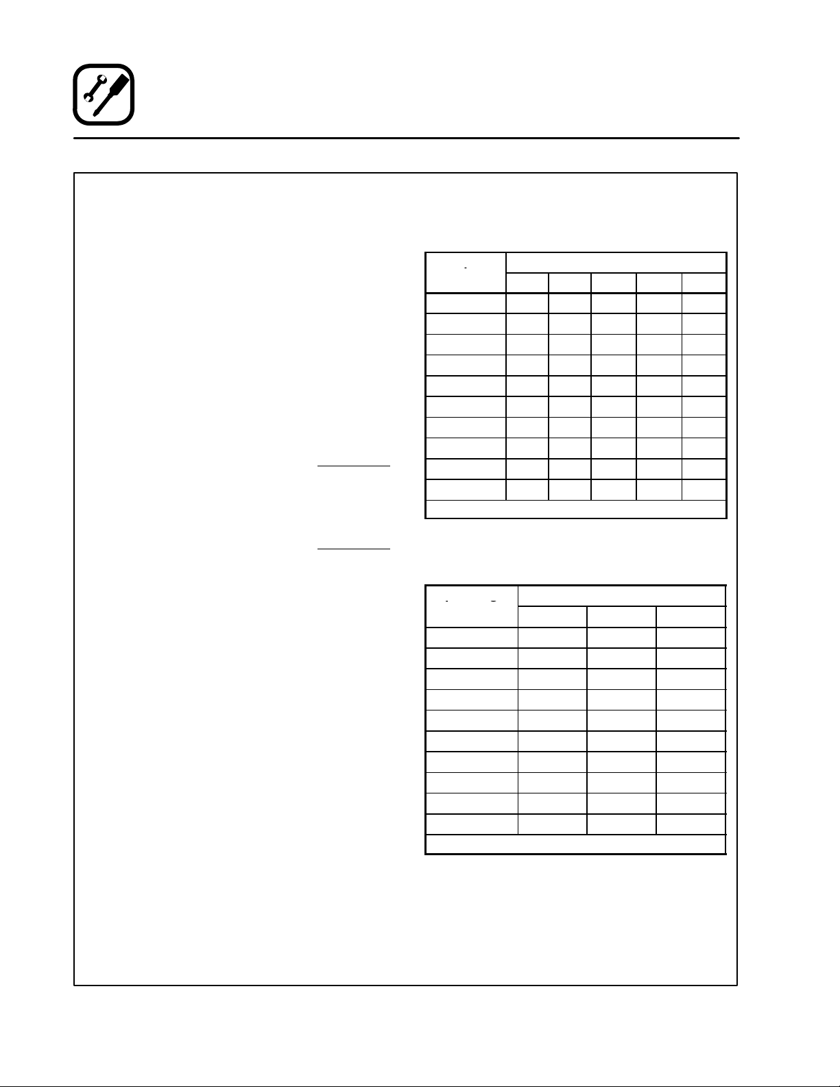
GAS SPECIFICATIONS - U.S., Canada and General Export
Natural Gas Propane Gas
US Units SI Units US Units SI Units
Heating Value 1000 BTU/cu.ft. 37.3 MJ/m
Specific Gravity (air=1.0) 0.63 0.63 1.53 1.53
Gas Manifold Pressure 3.5" W.C. .87 kPa 10" W.C. 2.49 kPa
Oven Input 27,500 BTU/hr
34,500 BTU/hr
Main Burner Orifice Size 38 MTD*
32 MTD*
Pilot Burner Orifice Size .021" dia. .55 mm .011" dia. .28 mm
Blodgett convection ovens represent the latest adĆ
vancement in energy efficiency, reliability, and
ease of operation. Heat normally lost, is recircuĆ
lated within the cooking chamber before being
vented from the oven: resulting in substantial reĆ
ductions in energy consumption and enhanced
oven performance.
3
2550 BTU/cu. ft. 95.0 MJ/m
8.1 kW
10.1 kW
2.6 mm
2.9 mm
27,500 BTU/hr
34,500 BTU/hr
1/16" dia.
50 MTD*
8.1 kW
10.1 kW
1.6 mm
1.75 mm
3
GAS SPECIFICATIONS - Australia
Oven Input - 32 MJ - 32 MJ
Main Burner Orifice Size 38 MTD* 2.6 mm 1/16" dia. 1.6 mm
Gas Manifold Pressure - .87 kPa - 2.49 kPa
NOTE: *Multiple Twist Drill
2
Page 7
Introduction
Oven Components
Combustion Cover - provides access to the
combustion compartment on gas ovens.
Combustion Compartment - contains combusĆ
tion burner on gas ovens.
Combustion Burner - provides heat to the bakĆ
ing chamber on gas ovens.
Control Panel - contains wiring and components
to control the oven operation.
Oven Racks - five racks are provided standard.
Additional racks are available.
Rack Supports - hold oven racks.
Blower Wheel Cover - located on the side interiĆ
or wall of the oven. Protects the blower wheel.
Blower Wheel - spins to circulate hot air in the
baking chamber.
Convection Motor - provides power to turn the
blower wheel.
Rack Support
Oven Rack
Figure 1
3
Page 8

Installation
Delivery and Location
DELIVERY AND INSPECTION
All Blodgett ovens are shipped in containers to
prevent damage. Upon delivery of your new oven:
D Inspect the shipping container for external damĆ
age. Any evidence of damage should be noted
on the delivery receipt which must be signed by
the driver.
D Uncrate the oven and check for internal damĆ
age. Carriers will accept claims for concealed
damage if notified within fifteen days of delivery
and the shipping container is retained for inĆ
spection.
The Blodgett Oven Company cannot assume
responsibility for loss or damage suffered in
transit. The carrier assumed full responsibility
for delivery in good order when the shipment
was accepted. We are, however, prepared to
assist you if filing a claim is necessary.
OVEN LOCATION
The well planned and proper placement of your
oven will result in long term operator convenience
and satisfactory performance.
The following clearances must be maintained beĆ
tween the oven and any combustible or nonĆcomĆ
bustible construction.
D Oven body right side - 6" (15 cm)
D Oven body left side - 6" (15 cm)
D Oven body back - 6" (15 cm)
D Oven body bottom - 6" (15 cm)
The following clearances must be available for serĆ
vicing.
D Oven body sides - 12" (30 cm)
D Oven body back - 12" (30 cm)
NOTE: On gas models, routine servicing can usuĆ
ally be accomplished within the limited
movement provided by the gas hose reĆ
straint. If the oven needs to be moved furĆ
ther from the wall, the gas must first be
turned off and disconnected from the oven
before removing the restraint. Reconnect
the restraint after the oven has been reĆ
turned to its normal position.
It is essential that an adequate air supply to the
oven be maintained to provide a sufficient flow of
combustion and ventilation air.
D Place the oven in an area that is free of drafts.
D Keep the oven area free and clear of all combusĆ
tibles such as paper, cardboard, and flammable
liquids and solvents.
D Do not place the oven on a curb base or seal to
a wall. This will restrict the flow of air and prevent
proper ventilation. Tripping of the blower moĆ
tor's thermal overload device is caused by an
excessive ambient temperature on the right
side of the oven. This condition must be corĆ
rected to prevent permanent damage to the
oven.
D The location must provide adequate clearance
for the air opening into the combustion chamĆ
ber.
Before making any utility connections to this oven,
check the rating plate to be sure the oven specifiĆ
cations are compatible with the gas and electrical
services supplied for the oven.
1. Remove the combustion compartment cover.
The rating plate is attached to the frame in the
combustion compartment.
4
Page 9
Installation
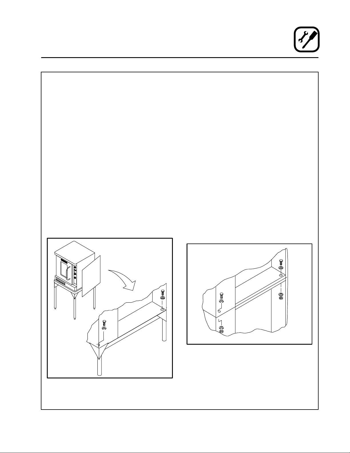
Stand Assembly
STAND OPTIONS
Small Stands Without Shelves
D The 5Ć3/4" (15cm) stand is used for a single
oven, when short legs are required for counterĆ
top use.
D The 7" (18cm) stand is used for a double
stacked oven, when the oven is to be located on
the floor.
Stands With Shelves
D Three stands, 16" (40cm), 19" (48cm), and 24"
(61cm) are available for different installation reĆ
quirements.
D The 33" (84cm) stand is used for a single oven
when counter space is limited.
Open Stands With Racks
D The 24" (61cm) or 33" (84cm) open stands are
available with a rack support system located beĆ
low the oven.
STAND ASSEMBLY
Small Stands Without Shelves
1. Place stand frame upside down on a work surĆ
face.
2. Attach one leg to each of the corner stud bolts
on the bottom of the stand top.
3. Place a lock washer and nut on each stud, and
tighten securely.
4. The stand is now ready for the oven assembly.
Stands With Shelves
1. Place stand frame upside down on a work surĆ
face.
2. Attach one leg to each of the corner stud bolts
on the bottom of the stand top.
3. Place a lock washer and nut on each bolt, and
tighten. DO NOT tighten leg bolts completely.
4. Place the shelf between the legs so that the
smooth top surface is facing the top of the
stand.
5. Align the shelf holes with the bolt holes found
near the bottom of each leg.
6. Insert a carriage bolt from the outside of the
leg, through the leg, and through the shelf corĆ
ner bracket.
7. Place a lock washer and nut on each bolt, and
tighten securely.
8. Tighten the leg frame bolts.
Figure 2
5
Page 10
Installation
Stand Assembly
Open Stands With Racks
1. Lay stand frame top down on the floor as
shown. See Figure 3.
2. Position the four leg assemblies and support
angles as shown. Attach with the 5/16Ć18 nuts
provided. DO NOT tighten leg bolts completely.
NOTE: Be sure the support angles and clips
are located correctly for your oven
configuration. See Figure 3.
3. Position the bottom shelf between the legs so
that the smooth top surface is facing the top
of the stand.
4. Align the shelf holes with the bolt holes found
near the bottom of each leg.
5. Insert a carriage bolt from the outside of the
leg, through the leg, and through the shelf corĆ
ner bracket.
Back of Stand
Rack Stop
Support
Angle,
RH
Support
Angle, LH
Rack
Support
6. Place a lock washer and nut on each bolt, and
tighten securely. See the Figure 2.
7. Repeat Steps 3-6 for the top shelf.
NOTE: Be sure the slots in the top shelf are
aligned with the support angles.
8. Insert the top of the rack stops into the two
back clips on the angle supports as shown. InĆ
sert the bottom of the rack stops into the slots
in the top shelf as shown.
9. Insert the rack supports into the remaining
four clips on the angle supports as shown. InĆ
sert the bottom of the rack supports into the
slots in the top shelf as shown.
10. Tighten all loose bolts.
Support
Angle
Top Shelf
(rear)
Rack
Support
Figure 3
6
Attach Rack Supports and Rack Stops
Page 11
OVEN ASSEMBLY TO STAND
Single Section
1. Place the assembled stand in the location
where the oven is going to be used.
2. Remove the side control compartment cover
and open the front control panel of a single
oven (or lower section).
3. With a tool, punch out the knockĆouts in the
oven bottom near each corner.
4. Set the oven on the stand. Center it to the frame.
5. Align the front, and rear bolt holes of the oven
with the bolt holes in the stand.
6. Insert a bolt and washer, from the top down
through each of the 2 holes.
7. Place a nut and washer on each of the 2 bolts,
and tighten securely.
8. Replace the oven's side control compartment,
and close the front control panel.
NOTE: For single section ovens only. For
double stacked ovens step 8 will be
completed once the ovens are stacked.
Installation
Oven Assembly
Double Section
1. Assemble the lower section to the stand as deĆ
scribed. DO NOT replace the side control
compartment or close the front control panel.
2. With a tool, punch out the knockĆouts in the
oven top of the lower oven.
3. Remove the side control compartment cover
and open the front control panel of the upper
oven.
4. With a tool, punch out the knockĆouts in the
bottom of the upper oven near each corner.
5. Set the upper oven on the lower oven.
6. Align the front, and rear bolt holes of the upper
oven with the bolt holes in the bottom oven.
7. Insert a bolt and washer, from the top down
through each of the 2 holes.
8. Place a nut and washer on each of the 2 bolts,
and tighten securely.
9. Replace the control compartment cover, and
close the front control panel on both of the
ovens.
Figure 4
Figure 5
7
Page 12
Installation
Oven Assembly
LEG ATTACHMENT
4" (10 cm legs)
1. Lay the oven on its back.
2. Screw the legs into the holes in the oven corĆ
ners. Tighten the hex nut at the top of each leg.
3. Tip the oven up on the legs.
4. Turn the adjustable leg feet to level the oven.
Figure 6
OVEN LEVELING
After assembly, the oven should be leveled and
moved to the operating location.
1. The oven can be leveled by adjusting the feet
or casters located on the bottom of each leg.
8
Page 13

Installation
Ventilation
On gas models the installation of a proper ventilaĆ
tion system cannot be over emphasized. This sysĆ
tem removes unwanted vapors and products of
combustion from the operating area.
This oven may be vented using either:
D A mechanically driven, canopy type, exhaust
hood, or
D A direct flue arrangement.
U.S. and Canadian installations
Refer to your local ventilation codes. In the abĆ
sence of local codes, refer to the National ventilaĆ
tion code titled, Standard for the Installation of
Equipment for the Removal of Smoke and Grease
Laden Vapors from Commercial Cooking EquipĆ
ment", NFPAĆ96ĆLatest Edition.
Australia and General Export installations
Installation must conform with Local and National
installation standards. Local installation codes
and/or requirements may vary. If you have any
questions regarding the proper installation and/or
operation of your Blodgett oven, please contact
your local distributor. If you do not have a local disĆ
tributor, please call the Blodgett Oven Company at
0011Ć802Ć860Ć3700.
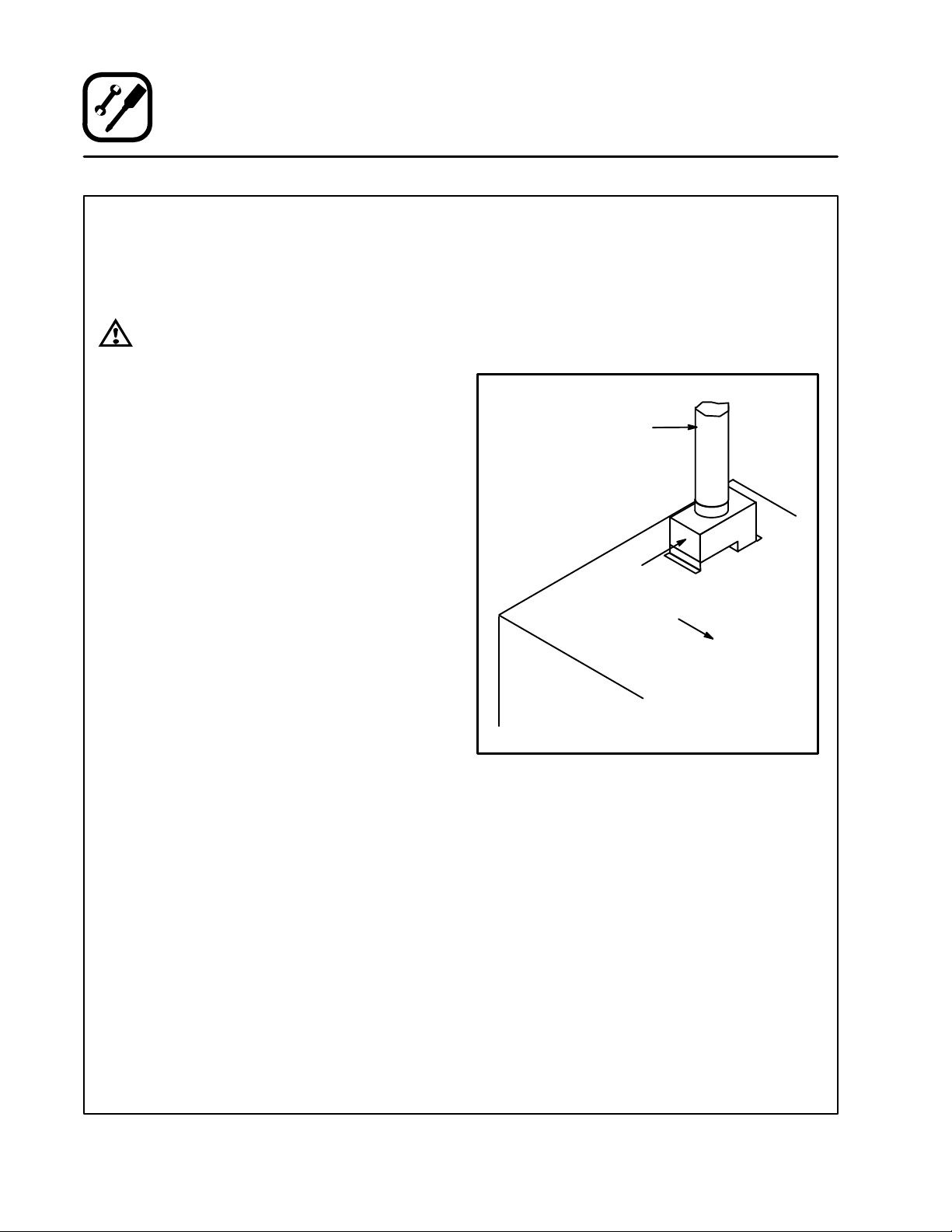
CANOPY TYPE EXHAUST HOOD
A mechanically driven, canopy type exhaust hood
is the preferred method of ventilation.
The hood should be sized to completely cover the
equipment plus an overhang of at least 6" (15 cm)
on all sides not adjacent to a wall. The distance
from the floor to the lower edge of the hood should
not exceed 7' (2.1m).
The total makeup and exhaust air requirements for
hood capacity should be approximately 19 CFM
for each oven section.
Installing the canopy hood draft diverter
Ovens ordered for hood venting are supplied with
a draft diverter. Install the draft diverter as follows:
1. Place the diverter over the flue connector with
the open area facing the right side of the oven.
See Figure 7.
2. Secure with the sheet metal screws provided.
Draft Diverter
WARNING:
Failure to properly vent the oven can be
hazardous to the health of the operator
and may result in operational problems,
unsatisfactory baking and possible damĆ
age to the equipment.
Damage sustained as a direct result of imĆ
proper ventilation will not be covered by
the manufacturer's warranty.
Front of
Oven
Figure 7
9
Page 14
Installation
Ventilation
DIRECT FLUE ARRANGEMENT
When the installation of a mechanically driven exĆ
haust hood is impractical the oven may be vented
by a direct flue arrangement.
WARNING!!
It is essential that the direct flue be
installed as follows. Incorrect installation
will result in unsatisfactory baking and
oven damage.
The flue must be class B or better with a diameter
of 6" (15 cm). The height of the flue should rise 6Ć8
ft (2Ć2.5 m) above the roof of the building or any
proximate structure. Never direct vent the oven
into a hood. The flue should be capped with a UL
Listed type vent cap to isolate the unit from exterĆ
nal environmental conditions.
The direct vent cannot replace air consumed and
vented by the oven. Provisions must be made to
supply the room with sufficient makeĆup air. Total
makeĆup air requirements for each oven section
should be approximately 19 CFM per section. To
increase the supply air entering the room, a venĆ
tilation expert should be consulted.
Installing the draft hood
Ovens ordered for direct venting are supplied with
a draft hood. Install the draft hood as follows:
1. Place the draft hood over the flue connector.
See Figure 8.
2. Secure both ends with the sheet metal screws
provided.
Flue
Draft Hood
Front of
Oven
10
Figure 8
Page 15
Installation
Utility Connections - Standards and Codes
THE INSTALLATION INSTRUCTIONS CONĆ
TAINED HEREIN ARE FOR THE USE OF QUALIĆ
FIED INSTALLATION AND SERVICE PERSONNEL
ONLY. INSTALLATION OR SERVICE BY OTHER
THAN QUALIFIED PERSONNEL MAY RESULT IN
DAMAGE TO THE OVEN AND/OR INJURY TO
THE OPERATOR.
Qualified installation personnel are individuals, a
firm, a corporation, or a company which either in
person or through a representative are engaged
in, and responsible for:
D the installation or replacement of gas piping
and the connection, installation, repair or servĆ
icing of equipment.
D the installation of electrical wiring from the elecĆ
tric meter, main control box or service outlet to
the electric appliance.
Qualified installation personnel must be experiĆ
enced in such work, familiar with all precautions
required, and have complied with all requirements
of state or local authorities having jurisdiction.
U.S. and Canadian installations
Installation must conform with local codes, or in
the absence of local codes, with the National Fuel
Gas Code, NFPA54/ANSI Z223.1-Latest Edition,
the Natural Gas Installation Code CAN/CGAĆ
B149.1 or the Propane Installation Code, CAN/
CGAĆB149.2 as applicable.
Installation must conform with local codes, or in
the absence of local codes, with the National ElecĆ
trical Code, ANSI/NFPA 70-Latest Edition and/or
Canadian National Electric Code C22.2 as appliĆ
cable.
Australia and General Export installations
Installation must conform with Local and National
installation standards. Local installation codes
and/or requirements may vary. If you have any
questions regarding the proper installation and/or
operation of your Blodgett oven, please contact
your local distributor. If you do not have a local disĆ
tributor, please call the Blodgett Oven Company at
0011Ć802Ć860Ć3700.
11
Page 16
Installation
p
pg
Gas Connection
GAS PIPING
A properly sized gas supply system is essential for
maximum oven performance. Piping should be
sized to provide a supply of gas sufficient to meet
the maximum demand of all appliances on the line
without loss of pressure at the equipment.
Example:
NOTE: BTU values in the following example are
for natural gas.
You purchase a DFGĆ50 convection oven to add to
your existing cook line.
1. Add the BTU rating of your current appliances.
Pitco Fryer 120,000 BTU
6 Burner Range 60,000 BTU
Deck Oven 50,000 BTU
Total 230,000 BTU
2. Add the BTU rating of the new oven to the toĆ
tal.
Previous Total 230,000 BTU
DFGĆ50 27,500 BTU
New Total 257,500 BTU
3. Measure the distance from the gas meter to
the cook line. This is the pipe length. Let's say
the pipe length is 40' (12.2 m) and the pipe
size is 1" (2.54 cm).
4. Use the appropriate table to determine the toĆ
tal capacity of your current gas piping.
The total capacity for this example is 320,000
BTU. Since the total required gas pressure,
257,500 BTU is less than 320,000 BTU, the
current gas piping will not have to be inĆ
creased.
NOTE: The BTU capacities given in the tables are
for straight pipe lengths only. Any elbows
or other fittings will decrease pipe capaciĆ
ties. Contact your local gas supplier if you
have any questions.
Maximum Capacity of Iron Pipe in Cubic Feet
of Natural Gas Per Hour
(Pressure drop of 0.5 Inch W.C.)
Pipe
Length (ft)
10 360 680 1400 2100 3950
20 250 465 950 1460 2750
30 200 375 770 1180 2200
40 170 320 660 990 1900
50 151 285 580 900 1680
60 138 260 530 810 1520
70 125 240 490 750 1400
80 118 220 460 690 1300
90 110 205 430 650 1220
100 103 195 400 620 1150
From the National Fuel Gas Code Part 10 Table 10Ć2
Maximum Capacity of Pipe in Thousands of
BTU/hr of Undiluted L.P. Gas at 11" W.C.
(Pressure drop of 0.5 Inch W.C.)
Pipe Length
(ft)
10 608 1146 3525
20 418 788 2423
30 336 632 1946
40 287 541 1665
50 255 480 1476
60 231 435 1337
70 215 404 1241
80 198 372 1144
90 187 351 1079
100 175 330 1014
From the National Fuel Gas Code Part 10 Table 10Ć15
Nominal Size, Inches
3/4" 1" 1Ć1/4" 1Ć1/4" 2"
Outside Diameter, Inches
3/4" 1" 1Ć1/2"
12
Page 17
Installation
Gas Connection
PRESSURE REGULATION AND TESTING
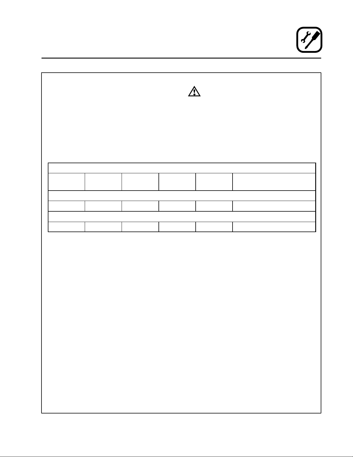
DFGĆ50 ovens are rated at 27,500 BTU/Hr. (8.1
kW) (29 MJ) or 34,500 BTU/Hr. (10.1 kW) (36 MJ)
per section. Each oven has been adjusted at the
factory to operate with the type of gas specified on
the rating plate.
Inlet Pressure
Natural Propane
Min Max Min Max
W.C. 7.0 10.5 11.0 13.0
kPa 1.43 2.61 2.74 3.23
Manifold Pressure
Natural Propane
W.C. 3.5 10.0
kPa .87 2.49
D Inlet Pressure - the pressure of the gas before
it reaches the oven.
D Manifold Pressure - the pressure of the gas
as it enters the main burner(s).
D Min - the minimum pressure recommended to
operate the oven.
D Max - the maximum pressure at which the
manufacturer warrants the oven's operation.
Each oven is supplied with a regulator to maintain
the proper gas pressure. The regulator is essenĆ
tial to the proper operation of the oven and
should not be removed. It is preset to provide the
oven with 3.5" W.C. (0.87 kPa) for natural gas and
10.5" W.C. (2.50 kPa) for Propane at the manifold.
DO NOT INSTALL AN ADDITIONAL REGULATOR
WHERE THE OVEN CONNECTS TO THE GAS
SUPPLY UNLESS THE INLET PRESSURE IS
ABOVE MAXIMUM.
Prior to connecting the oven, gas lines should be
thoroughly purged of all metal filings, shavings,
pipe dope, and other debris. After connection, the
oven should be checked for correct gas pressure.
The oven and its individual shutoff valve must be
disconnected from the gas supply piping system
during any pressure testing of that system at test
pressures in excess of 1/2 psig (3.45kPa).
The oven must be isolated from the gas supply
piping system by closing its individual manual
shutoff valve during any pressure testing of the
gas piping system at test pressures equal or less
than 1/2 psig (3.45kPa).
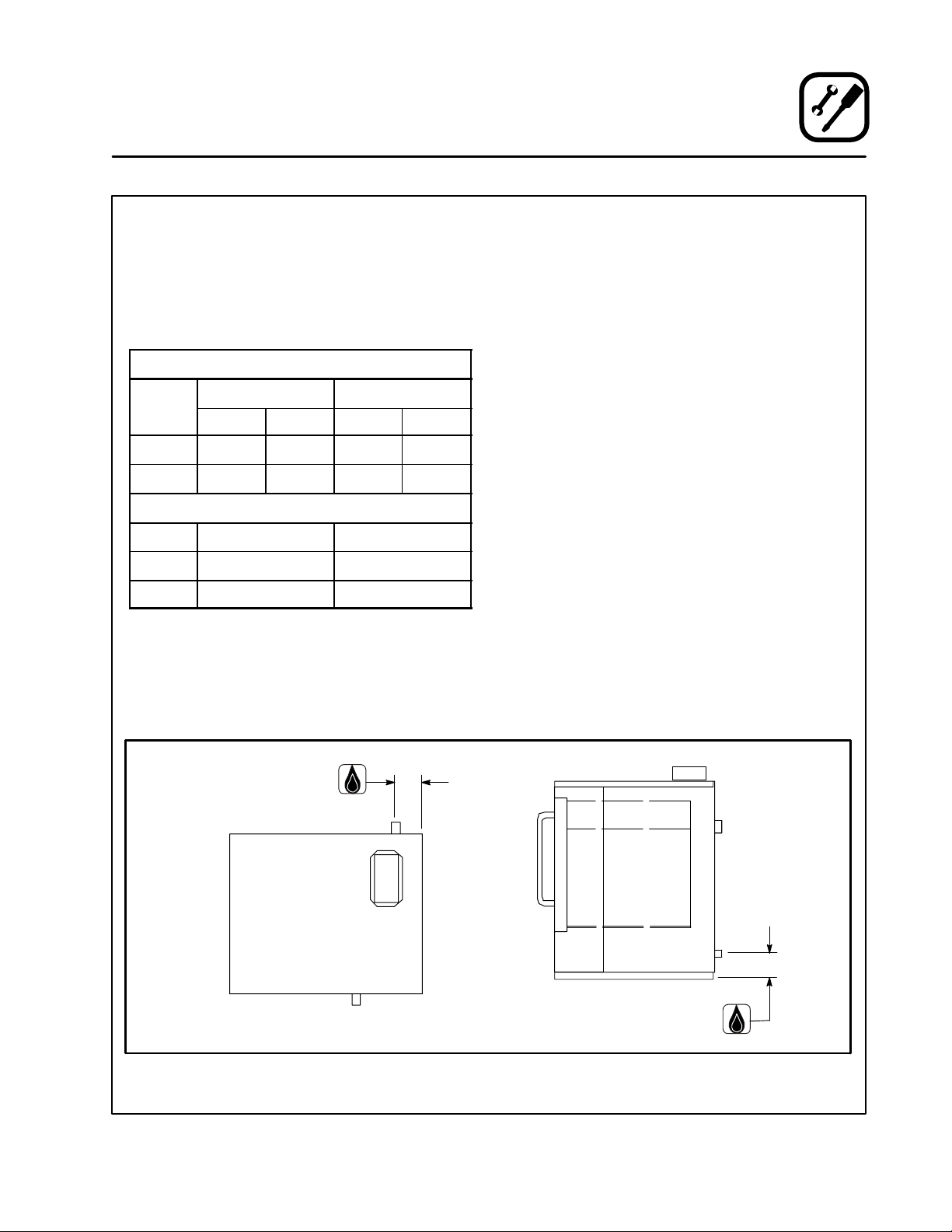
Gas Connection 4" (101.6 mm)
Gas Connection 2.75" (69.9 mm)
Figure 9
13
Page 18

Installation
Gas Connection
GAS HOSE RESTRAINT
If the oven is mounted on casters, a commercial
flexible connector with a minimum of 3/4" (1.9 cm)
inside diameter must be used along with a quick
connect device.
The restraint, supplied with the oven, must be
used to limit the movement of the unit so that no
strain is placed upon the flexible connector. With
the restraint fully stretched the connector should
be easy to install and quick connect.
The restraint (ie: heavy gauge cable) should be
1,000 lb. (453 kg) test load and should be attached
without damaging the building. DO NOT use the
gas piping or electrical conduit for the attachment
of the permanent end of the restraint! Use anchor
bolts in concrete or cement block. On wooden
walls, drive hi test wood lag screws into the studs
of the wall.
1. A 3/8" diameter hole has been provided on the
bottom of the oven just below the gas inlet. the
hole is sized to accept a clipĆon restraining
cable supplied with the flex hose.
WARNING!!
If the restraint is disconnected for any
reason it must be reconnected when the
oven is returned to its original position.
U.S. and Canadian installations
The connector must comply with the Standard for
Connectors for Movable Gas Appliances, ANSI
Z21.69 or Connectors For Moveable Gas ApĆ
pliances CAN/CGAĆ6.16ĆM87 and a quick disconĆ
nect device that complies with the Standard for
QuickĆDisconnect Devices for Use With Gas Fuel,
ANSI Z21.41 or Quick Disconnect For Use With
Gas Fuel CAN 1Ć6.9. Adequate means must be
provided to limit the movement of the appliance
without depending on the connection and the
quick disconnect device or its associated piping.
Australia and General Export installations
The restraint and quick connect must conform
with Local and National installation standards. LoĆ
cal installation codes and/or requirements may
vary. If you have any questions regarding the propĆ
er installation and/or operation of your Blodgett
oven, please contact your local distributor. If you
do not have a local distributor, please call the
Blodgett Oven Company at 0011Ć802Ć860Ć3700.
14
Page 19
Installation
Electrical Connection
Wiring diagrams are located in the motor access
panel and on the back of the oven.
This oven is supplied for connection to 115 volt
grounded circuits. The electric motor, indicator
lights and related switches are connected through
the 6' electric supply cord found at the rear of the
oven.
THE BLODGETT OVEN COMPANY CANNOT ASĆ
SUME RESPONSIBILITY FOR LOSS OR DAMAGE
SUFFERED AS A RESULT OF IMPROPER INSTALĆ
LATION.
ELECTRICAL SPECIFICATIONS
Model Hz Volts Phase Amps Electrical Connection
U.S. and Canadian Installations
DFGĆ50 60 115 1 5 Cord set provided
General Export Installations
WARNING!!
This appliance is equipped with three
prong grounding type plug for your
protection against shock hazard and
should be plugged directly into a properly
grounded three prong receptacle. DO
NOT cut or remove the grounding prong
from this plug.
(minimum size)
DFGĆ50 50 220Ć240 1 3 Size per local code
15
Page 20
Installation
Initial Startup
The following is a checkĆlist to be completed by
qualified personnel prior to turning on the
appliance for the first time.
j Open the manual shutĆoff valve at the rear of
the oven.
j Remove the control panel and combustion
covers.
j Turn the combination valve's manual shutĆoff
to the on position.
j Turn the selector switch to Cook, and the therĆ
mostat to 500_F (260_C).
With the main burner on, check the following.
j Verify there are no gas leaks, by checking all
gas connections with a soapy water solution.
j Verify that the inlet pressure is correct. The inĆ
let pressure can be checked at the pressure
tap located on the combination valve's inlet
side.
j Verify that the manifold pressure is correct.
The manifold pressure can be checked at the
pressure tap located on the combination
valve's outlet side.
j If the above pressure readings are set to the
recommended pressure requirements, allow
the oven to burnĆoff for 2 hours. If the pressure
readings are not set correctly, turn off the oven
and readjust accordingly.
ADJUSTMENTS ASSOCIATED WITH INITIAL
INSTALLATION
Each oven, and its component parts, have been
thoroughly tested and inspected prior to shipĆ
ment. However, it is often necessary to further
test or adjust the oven as part of a normal and
proper installation. These adjustments are the
responsibility of the installer, or dealer. Since
these adjustments are not considered defects
in material or workmanship, they are not covĆ
ered by the Original Equipment Warranty. They
include, but are not limited to:
D calibration of the thermostat
D adjustment of the doors
D burner adjustments
D leveling
D testing of gas pressure
D tightening of fasteners.
No installation should be considered complete
without proper inspection, and if necessary,
adjustment by qualified installation or service
personnel.
WARNING
The break in procedure burns off excess
oils present in the metals during fabricaĆ
tion. Smoke may be produced. Proper
ventilation is required.
16
Page 21

Operation
Safety Information
THE INFORMATION CONTAINED IN THIS SECĆ
TION IS PROVIDED FOR THE USE OF QUALIFIED
OPERATING PERSONNEL. QUALIFIED OPERATĆ
ING PERSONNEL ARE THOSE WHO HAVE
CAREFULLY READ THE INFORMATION CONĆ
TAINED IN THIS MANUAL, ARE FAMILIAR WITH
THE FUNCTIONS OF THE OVEN AND/OR HAVE
HAD PREVIOUS EXPERIENCE WITH THE OPĆ
ERATION OF THE EQUIPMENT DESCRIBED. ADĆ
HERENCE TO THE PROCEDURES RECOMĆ
MENDED HEREIN WILL ASSURE THE
ACHIEVEMENT OF OPTIMUM PERFORMANCE
AND LONG, TROUBLEĆFREE SERVICE.
Please take the time to read the following safety
and operating instructions. They are the key to the
successful operation of your Blodgett conveyor
oven.
SAFETY TIPS
For your safety read before operating
What to do if you smell gas:
D DO NOT try to light any appliance.
D DO NOT touch any electrical switches.
D Use an exterior phone to call your gas supplier
immediately.
D If you cannot reach your gas supplier, call the
fire department.
What to do in the event of a power failure:
D Turn all switches to off.
D DO NOT attempt to operate the oven until the
power is restored.
NOTE: In the event of a shutĆdown of any kind, alĆ
low a five (5) minute shut off period before
attempting to restart the oven.
General safety tips:
D DO NOT use tools to turn off the gas control. If
the gas cannot be turned off manually do not try
to repair it. Call a qualified service technician.
D If the oven needs to be moved for any reason,
the gas must be turned off and disconnected
from the unit before removing the restraint
cable. Reconnect the restraint after the oven
has been returned to its original location.
D DO NOT remove the control panel cover unless
the oven is unplugged.
17
Page 22
Operation
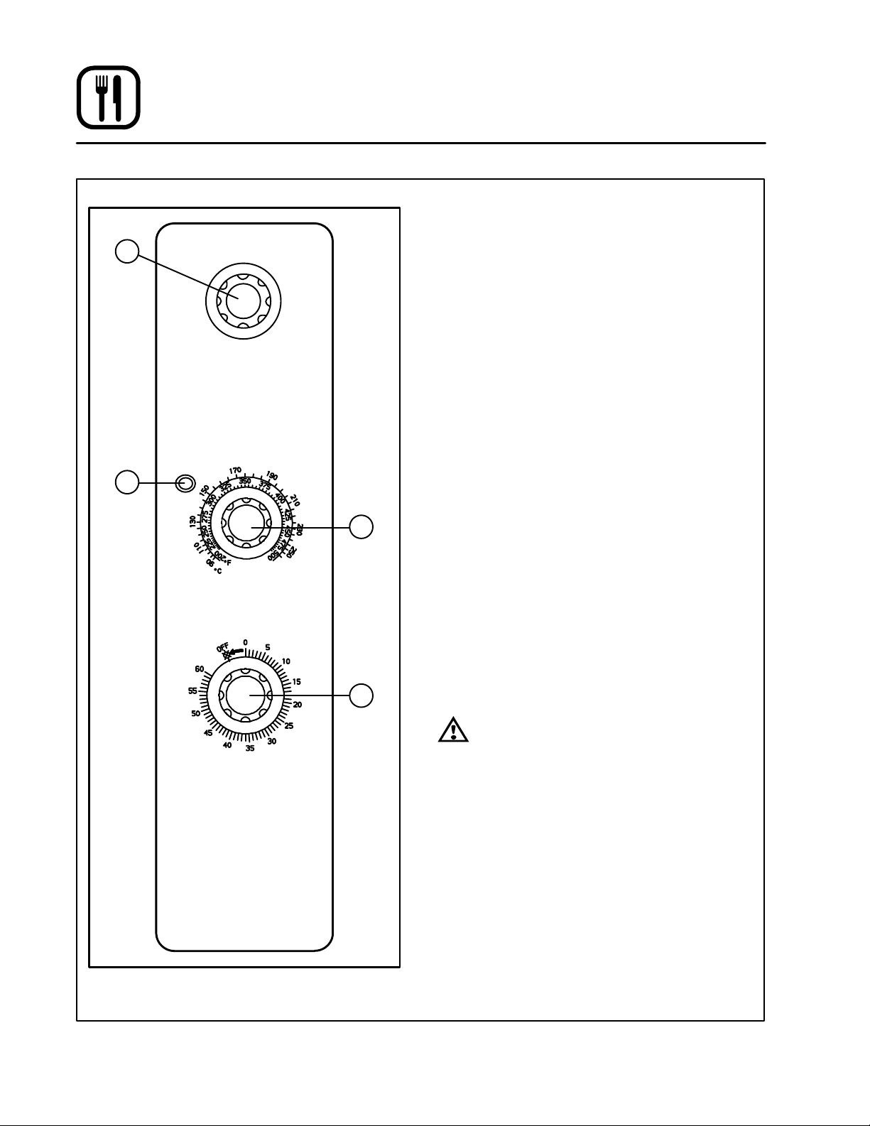
Solid State Manual Control
1
COOL
DOWN
OVEN OFF
COOK
CONTROL DESCRIPTION
1. SELECTOR SWITCH - controls power to the
oven for cook or cool down.
2. OVEN READY LIGHT - when lit indicates
burner operation. When the light goes out the
oven has reached operating temperature.
3. SOLID STATE THERMOSTAT Ć allows either 8
preĆset temperatures to be selected in accorĆ
dance with customer requirements, or an infiĆ
nite selection of temperatures from 200Ć500_F
(95Ć260_C). (infinite control shown)
4. TIMER - activates an electric buzzer that
sounds when the cook time expires.
2
LIGHT OFF
OVEN READY
SOLID STATE
THERMOSTAT
TIMER
OPERATION
1. Turn the SELECTOR Switch (1) to COOK. The
blower and control compartment cooling fan
operate and are controlled automatically by
3
the action of the doors.
2. Set the SOLID STATE THERMOSTAT (3) to the
desired setting or temperature.
3. Preheat until the OVEN READY LIGHT (2)
goes out.
4. Load product into the oven. Determine cook
time and set the TIMER (4).
5. When the buzzer sounds, remove the product
from the oven. Turn the TIMER knob (4) to OFF
to silence the buzzer.
4
6. Turn the SELECTOR Switch (1) to OVEN OFF.
WARNING!!
A complete five minute shutdown must be
observed before the oven is relighted.
Figure 10
18
Page 23
Operation
Solid State Digital Control
CONTROL DESCRIPTION
1. SELECTOR SWITCH - turns power to the
oven on or off. Allows selection of Cook or
Cool Down Modes.
2. DISPLAY - displays time or temperature and
other information related to oven function.
3. HEAT LAMP - lights when heater is on.
4. PULSE LAMP - lights when Pulsed Fan Mode
1
2
4
3
5
is turned on.
5. HOLD LAMP - lights when Hold Mode is
turned on.
6. DIAL - used to enter set points in display
7. START/STOP KEY - starts or stops the timer.
8. TIME KEY - used to show time in the display.
9. TEMP KEY - used to show set temperature in
the display.
NOTE: Actual temperature is shown while the
TEMP key is held down.
10. HOLD KEY - turns Hold Mode on or off.
11. PULSE KEY - turns Pulse Mode on or off.
PROGRAMMING
8
7
10
Figure 11
6
9
11
To set the cook temperature:
1. Press TEMP (9) key.
2. Rotate dial (6) to enter temperature.
To set the cook time:
1. Press TIME (8) key.
2. Rotate the dial (6) to enter time.
NOTE: Time is entered in hours : minutes or
minutes : seconds.
To set the hold time:
1. Press HOLD key (10) to turn hold mode on.
NOTE: HOLD light is on.
2. Rotate dial (6) to enter the hold temperature.
3. Press START/STOP key (7)
To set the pulse time:
1. Press PULSE KEY (11) to turn pulse mode on.
NOTE: Pulse light is on.
2. Rotate DIAL (6) to enter the pulse time. Pulse
time is a portion of the preĆset cook time.
19
Page 24

Operation
Solid State Digital Control
OPERATION
Cook Only:
1. Turn SELECTOR switch (1) to the desired poĆ
sition.
2. Enter the cook time and temperature.
3. Load product into oven.
NOTE: The display reads LOAD when the
oven is near the set temperature.
4. Press the START/STOP key (7). The timer beĆ
gins to count down.
5. When the cook timer reaches 00:00 the buzzĆ
er sounds and the display reads DONE.
6. Press the START/STOP key (7) to silence the
buzzer.
7. Remove the product.
Cook with Hold:
NOTE: HOLD light is on when hold mode is on
and off when hold mode is off.
1. Turn SELECTOR switch (1) to the desired poĆ
sition.
2. Enter the cook time and temperature.
3. Press the HOLD key (10). Enter the hold temĆ
perature.
4. Load product into oven.
NOTE: The display reads LOAD when the
oven is near the set temperature.
5. Push the START/STOP (7) key. Timer begins
to count down.
6. When the cook timer reaches 00:00 the buzzĆ
er sounds and the display reads DONE. The
buzzer turns off after a few seconds. The disĆ
play reads HOLD until the oven reaches the
hold temperature. Then the timer begins to
count up.
7. Push the START/STOP key (7) to stop timer.
8. Remove the product.
9. Push HOLD (10) key to turn off hold mode.
Cook with Pulse:
NOTE: PULSE light is on when pulse mode is on
and off when pulse mode is off.
1. Turn the SELECTOR SWITCH (1) to the deĆ
sired position.
2. Enter cook time and cook temperature.
3. Press PULSE KEY (11). Enter the pulse time.
NOTE: Pulse time is a portion of the cook time
and does not increase the previously
entered cook time.
4. Load product into oven.
NOTE: The display reads LOAD when the
oven is near the set temperature.
5. Push START/STOP KEY (7). The timer begins
to count down the cook time. The oven will be
in pulse mode for the set pulse time. Once the
set time has expired, the unit automatically
switches to cook mode and continues countĆ
ing down.
6. When the cook timer reaches 00:00 the buzzĆ
er sounds and the display reads DONE.
7. Push the START/STOP KEY (7) to turn the
buzzer off.
8. Remove the product.
WARNING!!
A complete five minute shutdown must be
observed before the oven is relighted.
20
Page 25
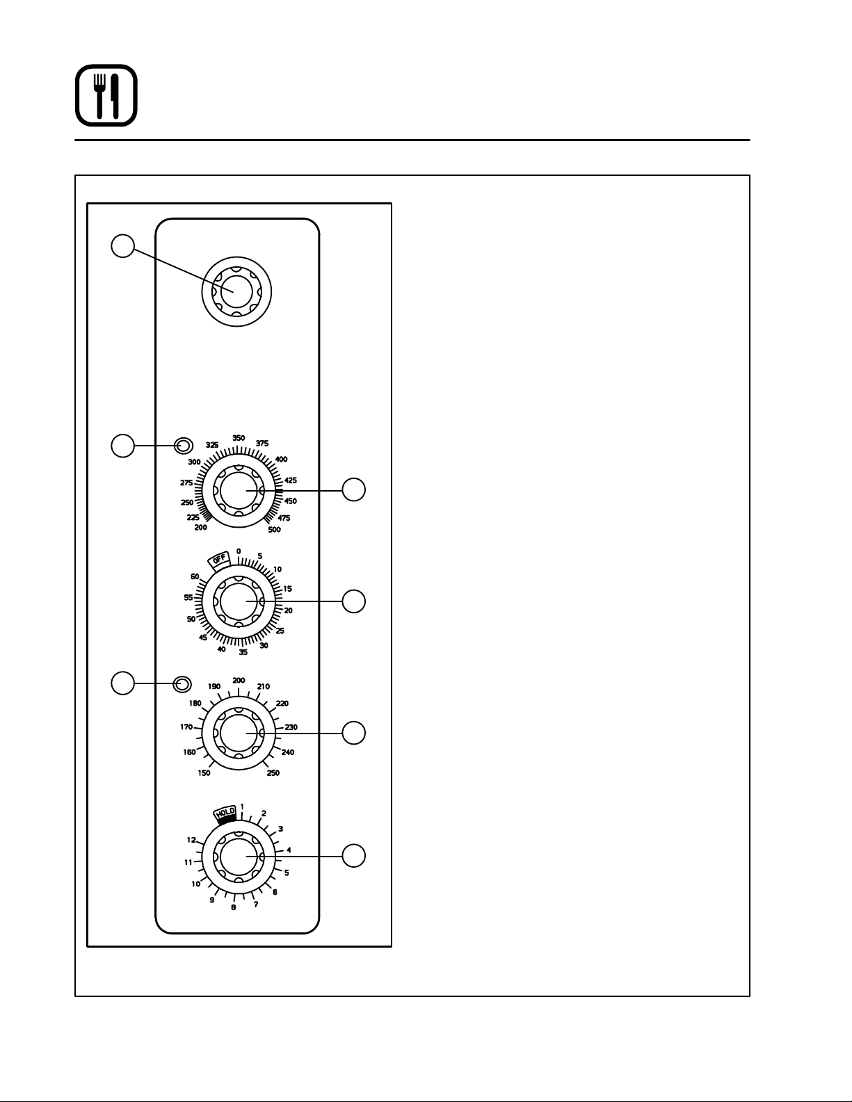
Operation
Pulse Plus
CONTROL DESCRIPTION
1. SELECTOR SWITCH - controls power to the
1
COOL
DOWN
OVEN OFF
COOK
2
3
FAN DELAY TIMER
oven for cook or cool down.
2. AMBER FAN DELAY LIGHT - indicates the
oven is in pulse plus.
3. FAN DELAY TIMER - activates pulse plus for
0-10 minutes. The blower and burners pulse
on for 30 seconds and off for 30 seconds for
the duration of time set.
4. RED INDICATOR LIGHT - indicates oven is in
the cook timer cycle.
5. COOK TIMER - activates an electric buzzer
that sounds when the cook time expires.
6. OVEN READY LIGHT - when lit indicates
burner operation. When the light goes out, the
oven has reached operating temperature.
7. SOLID STATE THERMOSTAT - allows either
8 preĆset temperatures to be selected in acĆ
cordance with customer requirements, or an
infinite selection of temperatures from
0Ć500_F (0Ć260_C). (infinite control shown)
4
6
LIGHT OFF
OVEN READY
TIMER
SOLID STATE
THERMOSTAT
Figure 12
OPERATION
1. Turn the SELECTOR Switch (1) to COOK.
2. Set the SOLID STATE THERMOSTAT (7) to the
5
desired cook temperature.
3. Preheat the oven until the OVEN READY
LIGHT (6) goes out.
4. Load product into the oven.
5. Set FAN DELAY TIMER (3) for the desired time
for pulse plus operation.
6. Set the COOK TIMER (5) for the desired cook
time.
7. When the buzzer sounds, remove product
from the oven. Turn the TIMER (5) knob to OFF
7
to silence the buzzer.
8. Turn the SELECTOR SWITCH (1) to OVEN
OFF.
WARNING!!
A complete five minute shutdown must be
observed before the oven is relighted.
21
Page 26
Operation
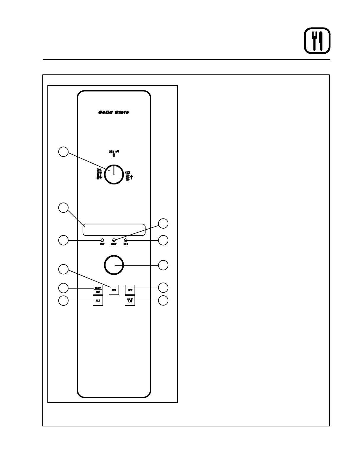
Cook and Hold Control
1
2
COOL
DOWN
LIGHT OFF
OVEN READY
OVEN OFF
COOK & HOLD
THERMOSTAT
COOK
COOK
CONTROL DESCRIPTION
1. SELECTOR SWITCH - controls power to the
oven for cook, cook & hold, and cool down.
2. OVEN READY LIGHT - when lit indicates
burner operation. When the light goes out, the
oven has reached operating temperature.
3. COOK THERMOSTAT - controls oven temĆ
perature in the cook cycle.
4. COOK TIMER - activates an electric buzzer
that sounds when the cook time expires.
5. HOLD THERMOSTAT - controls oven temĆ
perature in the hold cycle.
6. HOLD LIGHT Ć indicates the oven is in hold.
7. COOK & HOLD TIMER - controls the length
of cook time from 0 to 12 hours. When the
cook time ends, oven temperature control
3
switches from the cook to the hold thermostat.
COOK TIMER
4
HOLD
LIGHT
6
HOLD
THERMOSTAT
5
COOK & HOLD
TIMER
7
Figure 13
22
Page 27

Operation
Cook and Hold Control
OPERATION
Cook Only:
1. Turn the SELECTOR SWITCH (1) to COOK.
The blower and control compartment cooling
fans operate and are controlled automatically
by the action of the doors.
2. Set the COOK THERMOSTAT (3) to the deĆ
sired temperature.
3. Preheat until the OVEN READY LIGHT (2)
goes out.
4. Load product into the oven. Set the COOK
TIMER (4) to the desired cook time.
5. When the buzzer sounds, remove the prodĆ
uct. Turn the COOK TIMER (4) to OFF to siĆ
lence the buzzer.
6. Turn the SELECTOR SWITCH (1) to OVEN
OFF.
Cook and Hold:
1. Turn the SELECTOR SWITCH (1) to COOK.
The blower and control compartment cooling
fans operate and are controlled automatically
by the action of the doors.
2. Set the COOK THERMOSTAT (3) to the deĆ
sired cook temperature.
3. Set the HOLD THERMOSTAT (5) to the deĆ
sired hold temperature.
4. Preheat the oven until the OVEN READY
LIGHT (2) goes out.
5. Load product into the oven.
6. Turn the SELECTOR Switch (1) to COOK &
HOLD.
7. Set the COOK & HOLD TIMER (7) to the deĆ
sired cook time.
8. When the cook time ends the oven switches
to HOLD and the HOLD LIGHT (6) comes on.
9. The oven remains at the hold temperature unĆ
til the product is removed and the oven is
turned off.
NOTE: In the HOLD cycle, the blower goes on
and off with the burner.
10. Turn the SELECTOR SWITCH (1) to OVEN
OFF.
COOL DOWN
1. For COOL DOWN operation set the SELECĆ
TOR SWITCH (1) to COOL DOWN.
WARNING!!
A complete five minute shutdown must be
observed before the oven is relighted.
23
Page 28

Operation
CHĆPro3 (Solid State Programmable Digital Control)
COMPONENT DESCRIPTION
1. SELECTOR SWITCH - turns power to the
oven on or off. Allows selection of cook or cool
down modes and fan speed (if applicable).
2. TIME DISPLAY - gives cook time.
3. TIME ARROW KEYS - press to enter cook and/
or pulse times.
4. READY INDICATOR - when lit indicates the
oven has reached the setpoint temperature
and product may be loaded.
5. TEMPERATURE DISPLAY - gives cook and
hold temperatures.
6. HEAT INDICATOR - when lit indicates the
oven is heating.
7. TEMPERATURE ARROW KEYS - press to enĆ
ter cook and hold temperatures.
8. HOLD KEY - turns hold mode on or off.
9. TEMP KEY - press to display actual oven
temperature.
10. FAN KEY - turns pulse mode on or off. The
LED above the fan key is always on.
11. PRODUCT KEYS - three programmable keys.
12. MANUAL PRODUCT KEY - default product key
used for manual operation.
13. START KEY - press to begin a cook cycle.
14. PROGRAM KEY - press to enter programĆ
ming mode and save programmed settings.
15. STOP KEY - press to silence audible alarms
and cancel cook cycles.
11
13
1
2
4
5
6
8
9
3
7
10
12
15
14
Figure 14
24
Page 29

Operation
CHĆPro3 (Solid State Programmable Digital Control)
MANUAL OPERATION
NOTE: Press the arrow keys to change the cook
time and temperature at any point duringĆ
manual operation.
Cook Only:
1. Turn the SELECTOR SWITCH (1) to the deĆ
sired position.
2. Press the MANUAL PRODUCT KEY (12). The
manual and fan key LEDs light.
3. Press the TIME ARROW KEYS (3) to enter the
cook time.
4. Press the TEMPERATURE ARROW KEYS (7)
to enter the cook temperature.
5. The READY INDICATOR (4) lights when the
oven is at the set temperature. Load product
into the oven.
6. Press the START KEY (13). The TIME DISPLAY
(2) counts down. The manual key LED flashes.
7. When the cook time expires the LEDs and
both displays flash and an audible alarm
sounds. Press the STOP KEY (15) to silence
the alarm.
8. Remove the product.
Cook with Hold:
1. Turn the SELECTOR SWITCH (1) to the deĆ
sired position.
2. Press the MANUAL PRODUCT KEY (12). The
manual and fan key LEDs light.
3. Press the TIME ARROW KEYS (3) to enter the
cook time.
4. Press the TEMPERATURE ARROW KEYS (7)
to enter the cook temperature.
5. Press and hold the HOLD KEY (8). At the same
time use the TEMPERATURE ARROW KEYS
(7) to enter the hold temperature. The hold key
LED lights.
6. The READY INDICATOR (4) lights when the
oven is at the set temperature. Load product
into the oven.
7. Press the START KEY (13). The TIME DISPLAY
(2) counts down. The manual key LED flashes.
8. When the cook time expires both displays
flash and an audible alarm sounds for several
seconds then self cancels. The hold key LED
flashes. The time display begins to count up
while the oven cools to the hold temperature.
When the oven reaches the hold temperature
the time display resets to 00:00 then begins to
count up the hold time. The fan cycles with
heat demand in the hold mode.
9. Press the STOP KEY (15) to stop the timer.
10. Remove the product.
11. Push the HOLD KEY (8) to turn off hold mode.
Cook with Pulse:
1. Turn the SELECTOR SWITCH (1) to the deĆ
sired position.
2. Press the MANUAL PRODUCT KEY (12). The
manual and fan key LEDs light.
3. Press the TEMPERATURE ARROW KEYS (7)
to enter the cook temperature.
4. Press the FAN KEY (10). The fan key LED
flashes. Use the TIME ARROW KEYS (3) to enĆ
ter the pulse time.
5. The READY INDICATOR (4) lights when the
oven is at the set temperature. Load product
into the oven.
6. Press the START KEY (13). The manual key
LED flashes. The TIME DISPLAY (2) counts
down. The fan cycles on for 30 seconds then
off for 30 seconds until the set pulse time has
expired.
7. When the pulse time expires both displays
flash and an audible alarm sounds. Press the
STOP KEY (15) to silence the alarm.
8. Remove the product.
Oven Shut Down:
1. Turn the SELECTOR SWITCH (1) to OVEN OFF.
25
Page 30

Operation
CHĆPro3 (Solid State Programmable Digital Control)
PROGRAMMING THE MANUAL KEY DEFAULT
1. Turn the SELECTOR SWITCH (1) to the deĆ
sired position.
2. Press the MANUAL KEY (12). The manual and
fan key LEDs light.
3. Press the PROGRAM KEY (14).
4. Press the TIME ARROW KEYS (3) to enter the
cook time.
5. Press the TEMPERATURE ARROW KEYS (7)
to enter the cook temperature.
6. For Cook and Hold - Press and hold the
HOLD KEY (8). At the same time use the TEMĆ
PERATURE ARROW KEYS (7) to enter the
hold temperature. The hold key LED lights.
For Cook with Pulse - Press the FAN KEY
(10). Use the TIME ARROW KEYS (3) to enter
the pulse time. The fan key LED flashes.
7. Press the PROGRAM KEY (14) to save the proĆ
gram settings.
MANUAL KEY DEFAULT OPERATION
1. Turn the SELECTOR SWITCH (1) to the deĆ
sired position.
2. Press the MANUAL KEY (12). The applicable
LEDs light.
3. Press the START KEY (13). The TIME DISPLAY
(2) counts down. The manual key LED flashes.
NOTE: In Cook with Pulse the fan LED flashes.
NOTE: Press the arrow keys to change the
cook time and temperature at any
point during manual key operation.
4. When the cook time expires the applicable
LEDs and both displays flash and an audible
alarm sounds.
5. Press the STOP KEY (15) to silence the alarm.
NOTE: In Cook & Hold the alarm self cancels.
The oven cools to the hold temperaĆ
ture and the time display counts up.
6. Remove the product.
7. Turn the SELECTOR SWITCH (1) to OFF to
shut down the oven.
PROGRAMMING THE PRODUCT KEYS
1. Turn the SELECTOR SWITCH (1) to the deĆ
sired position.
2. Press the desired PRODUCT KEY (11). The
product and fan key LEDs light.
3. Press and hold the PROGRAM KEY (14) until
the corresponding LED flashes, approximateĆ
ly five seconds.
4. Press the TIME ARROW KEYS (3) to enter the
cook time.
5. Press the TEMPERATURE ARROW KEYS (7)
to enter the cook temperature.
6. For Cook and Hold - Press and hold the
HOLD KEY (8). At the same time use the TEMĆ
PERATURE ARROW KEYS (7) to enter the
hold temperature. The hold key LED lights.
For Cook with Pulse - Press the FAN KEY
(10). Use the TIME ARROW KEYS (3) to enter
the pulse time. The fan key LED flashes.
7. Press the PROGRAM KEY (14) to save the proĆ
gram settings.
PRODUCT KEY OPERATION
1. Turn the SELECTOR SWITCH (1) to the deĆ
sired position.
2. Press the desired PRODUCT KEY (11). The
applicable LEDs light.
3. Press the START KEY (13). The TIME DISPLAY
(2) counts down. The product key LED flashes.
NOTE: In Cook with Pulse the fan LED flashes.
4. When the cook or pulse time expires the appliĆ
cable LEDs and both displays flash and an auĆ
dible alarm sounds.
5. Press the STOP KEY (15) to silence the alarm.
NOTE: In Cook and Hold the alarm self canĆ
cels. The oven cools to the hold temĆ
perature and the time display counts
up.
6. Remove the product.
7. Turn the SELECTOR SWITCH (1) to OFF to
shut down the oven.
26
Page 31

1
19
14
15
16
Operation
Blodgett IQ2T Vision Control
COMPONENT DESCRIPTION
1. OVEN POWER SWITCH - controls power to
the oven.
2. DISPLAY - displays temperature and other
controller related information.
3. PROGRAM KEY - press to enter the programĆ
18
2
3
5
6
4
7
8
9
10
11
12
13
17
ming mode.
4. PROGRAM ARROW KEYS - use to move
through programming menus and options
5. HEAT LED - when lit indicates the control is
calling for heat.
6. PROG LED - when lit indicates the controller
is in the programming mode.
7. HIGH FAN LED - when lit indicates the fan is
running at high speed.
8. LOW FAN LED - when lit indicates the fan is
running at low speed.
9. SCAN KEY - Press to view time remaining on
multiple cook cycles and to review recipe proĆ
gramming.
10. COOL DOWN KEY - press to enter the cool
down mode.
11. TEMP/TOGGLE/CLEAR KEY - press during
programming to toggle options.
12. HOLD KEY - press to enter hold mode.
13. SET BACK KEY -
14. PRODUCT KEYS (1Ć10) - assigns a key to a
programmed recipe and begins a proĆ
grammed cooking process. Also used to enĆ
ter numeric values in the programming mode.
15. PRODUCT LEDS - when lit indicate which
product keys are currently in use or proĆ
grammed for the current oven temperature
and fan speed.
16. SHELF KEYS (1Ć5) - assigns a shelf key.
17. LIGHTS SWITCH - controls interior lights.
18. GAS ON/OFF SWITCH - press to shut off gas
to the oven.
19. RATE SWITCH - switches oven between
standard rate (60,000 BTU) and high rate
(80,000 BTU) while in high fan.
NOTE: High rate is disabled with low fan.
Figure 15
27
Page 32

Operation
Blodgett IQ2T VisionControl
OVEN OPERATION
Oven Startup:
1. Toggle the POWER SWITCH (1) to ON. The
display gives the software revision level. The
oven preheats to the lowest programmed first
stage temperature. The LEDS (15) for all prodĆ
ucts with the same first stage temperature
light.
Single Product Cooking Procedure:
NOTE: If the led next to the desired product key is
lit skip step 1.
1. Press the desired PRODUCT KEY (14). The
oven preheats to the first stage temperature for
the selected product. When the oven reaches
10_ of the preheat temperature an alarm
sounds and the DISPLAY (2) read:
LOAD
2. Load the product into the oven. Press the deĆ
sired PRODUCT KEY (14).
If the shelf timing function is toggled to the
on position for that product key, the DISĆ
PLAY (2) reads:
PICK SHLF
Press a SHELF KEY (16) to assign the product
to that shelf and start the cook cycle. Within
five seconds, the DISPLAY (2) scrolls the prodĆ
uct name and shelf number and counts down
the remaining cook time.
If the shelf timing function is toggled to the
off position for that product, pressing the
product key will start the cook cycle. The DISĆ
PLAY (2) scrolls the product name and counts
down the remaining cook time.
NOTE: If the selected product has a cook time
of greater than 59:59 the DISPLAY (2)
switches to hours:minutes.
NOTE: If the selected product is a single stage
recipe the LEDS for all single stage
products with the same cook temperaĆ
ture and fan speed will light. If the seĆ
lected product is a multiple stage recĆ
ipe no other product LEDS will light.
NOTE: Press and hold the selected product
key for three seconds to cancel the
cook cycle for normal operation. To
cancel the cook cycle when using
shelf timing, press and hold the correĆ
sponding SHELF KEY (16) for 3 secĆ
onds.
3. When the cook time expires an alarm sounds
and the DISPLAY (2) reads:
DONE
Product name
4. Press the selected product key to silence the
alarm. Remove the product. If shelf timing is
used, press the flashing SHELF KEY (16) to siĆ
lence the alarm.
Multiple Batch Cooking Procedure:
This procedure is for single stage recipes with the
same cook temperature and fan speed only.
NOTE: If the led next to the first desired product
key is lit skip step 1.
1. Press the first desired PRODUCT KEY (14).
The LEDS for all recipes with the same cook
temperature and fan speed will light.
The oven preheats to the cook temperature for
the selected product. When the oven reaches
10_ of the preheat temperature an alarm
sounds and the DISPLAY (2) reads:
LOAD
28
Page 33

Operation
Blodgett IQ2T Vision Control
2. Load the product into the oven. Press the deĆ
sired PRODUCT KEY (14).
If the shelf timing function is toggled to the
on position for that product key, the DISĆ
PLAY (2) reads
PICK SHLF
Press a SHELF KEY (16) to assign the product
to that shelf and start the cook cycle. Within
five seconds, the DISPLAY (2) scrolls the prodĆ
uct name and shelf number and counts down
the remaining cook time.
If the shelf timing function is toggled to the
off position for that product, pressing the
product key will start the cook cycle. The DISĆ
PLAY (2) scrolls the product name and counts
down the remaining cook time.
3. Load the second product. Press the desired
PRODUCT KEY (14). the DISPLAY (2) reads
PICK SHLF
Press a SHELF KEY (16) to assign the product
to that shelf and start the cook cycle for prodĆ
uct two.
NOTE: Only products with lighted LEDS may
be selected.
Repeat step 3 for additional products.
4. The DISPLAY (2) scrolls the product name and
counts down the remaining cook time for the
product with the least time remaining.
NOTE: To view the remaining cook time for
the other products press and hold the
SCAN KEY (9). The display cycles
through the remaining cook times for
each product. Only the led for the
product with the cook time displayed
will be lit.
5. When a cook time expires an alarm sounds.
The display reads
DONE
The led for the finished product lights. All other
LEDS are dark.
6. Press the SHELF KEY (16) for the finished
product to silence the alarm. Remove the
product. Close the oven door. The DISPLAY
(2) scrolls the product name and counts down
the remaining cook time for the product with
the least time remaining.
7. When the cook time expires an alarm sounds
and the display reads:
DONE
8. Press the SHELF KEY (16) to silence the
alarm. Remove the product.
Oven Cool Down:
1. Close the oven door. Press the COOL DOWN
KEY (10).
NOTE: Cool down cannot be activated with the
oven door open. Once the cool down cycle
has begun the doors may be opened to
speed the cooling process.
To Review Repipe Programming:
1. Press the SCAN KEY (9). The display reads:
RECIPE REVIEW
Select Product
The LEDs (15) for all previously programmed
product keys light. Press the PRODUCT KEY
(14) you wish to review. The display gives the
recipe cook time for stage 1. Use the PROĆ
GRAM ARROW KEYS (4) to scroll through the
recipe programming for the selected product
key.
2. The control will exit recipe review after 30 secĆ
onds if no key is pressed.
29
Page 34

Operation
Blodgett IQ2T Vision Control
PRODUCT KEY PROGRAMMING
To enter the product programming mode
1. Press and hold the PROGRAM KEY (3). The
DISPLAY (2) reads:
Prod Cnt
Programming
Use the PROGRAM ARROW KEYS (4) to highĆ
light Programming. Press the PROGRAM KEY
(3) to select. The display reads:
ENTER CODE
Use the PRODUCT KEYS (14) to enter the proĆ
gramming access code 1724. Press the PROĆ
GRAM KEY (3). The display reads:
RECIPE
Press the PROGRAM KEY (3). All of the prodĆ
uct LEDSs will light and the display reads:
Select Product
To Program
To program the product
4. The display reads:
Shelf Cook
XXX
Definition: Shelf cook enables the operĆ
ator to reference product to one of the
five shelf positions in the oven. At the
end of a shelf cooking cycle the oven
will display the name of the product and
the shelf number that is ready to be
pulled. Shelf cooking is not available
for multiĆstage recipes.
Use non shelf cooking when you do not
need to reference product to one of the
five shelf positions in the oven. Non
shelf cooking may be used for single
stage recipes and MUST be use for
multiĆstage recipes.
Use the PROGRAM ARROW KEYS (4) to seĆ
lect either YES (for shelf cooking) or NO (for
non shelf cooking). Press the PROGRAM KEY
(3).
To select the product to program
2. Press the desired product key. The display
reads:
All
Name
With All highlighted, press the PROGRAM
KEY (3). The display reads:
Product Name
AAA
The first alphabetical listing in the product
name library appears.
3. To change the product name, use the PROĆ
GRAM ARROW KEYS (4) to scroll through the
product name library. When the desired prodĆ
uct name is highlighted, press the PROGRAM
KEY (3) to select.
5. The display reads:
Stage 1 Time
XX:XX
Use the PRODUCT KEYS (14) to enter the deĆ
sired cook time. Press the PROGRAM KEY (3).
6. The display reads:
Stage 1 Temp
XXXF (or C)
Use the PRODUCT KEYS (14) to enter the deĆ
sired cook temperature. Press the PROGRAM
KEY (3).
30
Page 35

Operation
Blodgett IQ2T Vision Control
7. The display reads:
Stage 1 Timing
XXX
Definition: There are 3 options for timĆ
ing mode when shelf cooking: Straight,
Flex and Sensitivity. Straight has no
time adjustment. Flex adjusts the cook
time to compensate for any difference
between the setpoint and actual temĆ
perature. Sensitivity enables a product
key to have a flex adjustment for each
of the five shelves. Sensitivity values are
set in the manager level programming.
NOTE: Sensitivity is only available when usĆ
ing shelf cooking.
Use the PROGRAM ARROW KEYS (4) to seĆ
lect the desired timing mode. Press the PROĆ
GRAM KEY (3).
8. The display reads:
Stage 1 Fan Spd
XX
Use the PROGRAM ARROW KEYS (4) to seĆ
lect either HIGH or LOW fan speed. Press the
PROGRAM KEY (3).
9. The display reads:
Stage 1 Fan On
XX:XX
Use the PRODUCT KEYS (14) to enter the deĆ
sired length of the time the fan should be on
in the pulse cycle. Press PROGRAM KEY (3).
The display reads:
Stage 1 Fan OFF
XX:XX
Use the PRODUCT KEYS (14) to enter the deĆ
sired length of the time the fan should be off
in the pulse cycle. Press the PROGRAM KEY
(3).
10. If you are programming a product using shelf
cooking skip to step 11.
If you are programming a product that does
not use shelf cooking the display reads:
Stage 2 Time
XX:XX
Repeat steps 5 through 10 for each remaining
stage. If you are programming a single stage
recipe without shelf cooking enter at time of
00:00 for stage 2.
11. The display reads:
Alarm 1 Time
XX:XX
Stage 1 Fan Cyc
XXX
Definition: There are 3 options for fan
cycle time: Pulse, Heat and Full. Pulse
allows the fan to turn on and off as proĆ
grammed. Heat allows the fan to operĆ
ate with heat only. Full provides continuĆ
ous fan operation when door is closed.
Use the PROGRAM ARROW KEYS (4) to seĆ
lect the fan cycle. If heat or full are selected
skip to step 10. If pulse is selected the display
reads:
Definition: If you would like the alarm to
sound prior to the completion of the
cook cycle you may program it here.
The alarm time counts up from the beĆ
ginning of the cook cycle. For example,
if you want an alarm 9 minutes into the
cook cycle, program the alarm time at
9:00.
Use the PRODUCT KEYS (14) to enter the time
for the first alarm to sound. If 00:00 is entered
for an alarm time, skip to step 12.
Press the PROGRAM KEY (3). If a time other
than 00:00 is entered the display reads:
31
Page 36

Operation
Blodgett IQ2T Vision Control
Alarm 1 Name
XXX
To change the alarm name, use the PROĆ
GRAM ARROW KEYS (4) to scroll through the
alarm name library.
Press the PROGRAM KEY (3). The display
reads:
Alarm 1 Done
XXX
Use the PROGRAM ARROW KEYS (4) to seĆ
lect either AUTOMATIC or MANUAL.
Press the PROGRAM KEY (3). The display
reads:
Alarm 1 Tone
XXX
Use the PROGRAM ARROW KEYS (4) to seĆ
lect either NONE, SHORT, MEDIUM, LONG,
DOUBLE, or LONG/SHORT.
Press the PROGRAM KEY (3). The display
reads:
Alarm 2 TIme
XXX
Repeat step 11 for alarm 2. If no Alarm 2 is deĆ
sired, enter a time of 0.
Use the PRODUCT KEYS (14) to enter desired
hold temperature. The minimum hold temperĆ
ature is 140F. Press the PROGRAM KEY (3).
14. The display reads:
Hold Done
XXX
Use the PROGRAM ARROW KEYS (4) to seĆ
lect either AUTOMATIC or MANUAL. Press the
PROGRAM KEY (3).
15. The display reads:
Hold Fan Speed
XXX
Use the PROGRAM ARROW KEYS (4) to seĆ
lect HIGH or LOW. Press the PROGRAM KEY
(3).
To exit the program mode
16. The display reads:
Exit
All
Use the PROGRAM ARROW KEYS (4) to scroll
down until exit is highlighted. Press the PROĆ
GRAM KEY (3). The display reads:
12. Press the PROGRAM KEY (3). The display
reads:
Hold Time
XX:XX
Use the PRODUCT KEYS (14) to enter desired
hold time. If a hold time of 00:00 is entered skip
to step 13. Press the PROGRAM KEY (3).
13. The display reads:
Hold Temp
XXXF
Recipe
Exit
To program another product key select recipe.
To exit the progam mode select exit. The disĆ
play reads:
Product Cnt
Programming
Use the PROGRAM ARROW KEYS (4) to scroll
down until exit is highlighed. Press the PROĆ
GRAM KEY (3) to exit the programming mode.
32
Page 37

Operation
Blodgett IQ2T Vision Control
SYSTEM LEVEL PROGRAMMING
Entering the system programming mode
1. Press and hold the PROGRAM KEY (3). The
display reads:
Prod Cnt
Programming
Use the PROGRAM ARROW KEYS (4) to highĆ
light Programming. Press the PROGRAM KEY
(3) to select. The display reads:
ENTER CODE
Use the PRODUCT KEYS (14) to enter the proĆ
gramming access code 6647. Press the PROĆ
GRAM KEY (3). The display reads:
System
ProdName Lib
Programming the SYSTEM options
1. With System highlighted, press the PROĆ
GRAM KEY (3) to select. The display reads:
Appliance Type
XXX
Use the PROGRAM ARROW KEYS (4) to highĆ
light electric half, electric full, gas half or gas
full. Press the PROGRAM KEY (3) to select the
correct appliance type.
If the appliance type is changed the display
scrolls "Are you sure, existing recipes will be
cleared?" Use the PROGRAM ARROW KEYS
(4) to select either YES or NO.
2. The display reads:
Language
XXX
Use the PROGRAM ARROW KEYS (4) to seĆ
lecteither English or Other. Press the PROĆ
GRAM KEY (3) to select the desired language.
3. The display reads:
Tone Volume
XXX
Use the PROGRAM ARROW KEYS (4) to seĆ
lect None, 1, 2, 3 or 4. Press the PROGRAM
KEY (3) to select the desired level for all audiĆ
ble signals.
4. The display reads:
Temperature
XXX
Use the PROGRAM ARROW KEYS (4) to seĆ
lect either F or C. Press the PROGRAM KEY (3)
to select the desired temperature units.
5. The display reads:
Hold Time
XXX
Use the PRODUCT KEYS (14) to enter a hold
time. Press the PROGRAM KEY (3).
6. The display reads:
Setback Time
XXX
Definition - Setback time is an energy
savings feature that automatically lowĆ
ers the cavity temperature when the
oven is idle.
Use the PRODUCT KEYS (14) to enter a setĆ
back time. Press the PROGRAM KEY (3).
7. The display reads:
Shelf Sense
XXX
Definition - If you are using sensitivity
as a timing mode for single stage stage
recipes this feature must be turned on.
33
Use the PROGRAM ARROW KEYS (4) to seĆ
lect either Yes or No. Press the PROGRAM
KEY (3).
Page 38

Operation
Blodgett IQ2T Vision Control
8. The display reads:
Shelf 1 Sens
XXX
Use the PRODUCT KEYS (14) to enter sensiĆ
tivity level of 1-9 for shelf 1. Press the PROĆ
GRAM KEY (3). Repeat for shelves 2Ć5.
9. The display reads:
Preheat Time
XXX
Definition - This function programs
time for the oven to idle after reaching
the preheat temperature allowing heat
to saturate the oven cavity. The preheat
time only applies to the initial preheat
after a cold start. This is strictly a
prompt, the user may begin a bake
cycle even with the preheat prompt disĆ
played.
Use the PRODUCT KEYS (14) to enter a preĆ
heat time. Press the PROGRAM KEY (3).
10. The display reads:
Recipe Stage
YES
Use the PROGRAM ARROW KEYS (4) to seĆ
lect either Yes or No. Press the PROGRAM
KEY (3).
11. The display reads:
Recipe Name
YES
This enables you to program a product name.
Use the PROGRAM ARROW KEYS (4) to seĆ
lect either Yes or No. Press the PROGRAM
KEY (3).
12. The display reads:
Use the PROGRAM ARROW KEYS (4) to seĆ
lect either Yes or No. Press the PROGRAM
KEY (3).
13. The display reads:
Recipe Fan Speed
YES
Use the PROGRAM ARROW KEYS (4) to seĆ
lect either Yes or No. Press the PROGRAM
KEY (3).
14. The display reads:
Recipe Fan Cycle
YES
Use the PROGRAM ARROW KEYS (4) to seĆ
lect either Yes or No. Press the PROGRAM
KEY (3).
15. The display reads:
Recipe Alarm
YES
Use the PROGRAM ARROW KEYS (4) to seĆ
lect either Yes or No. Press the PROGRAM
KEY (3).
16. The display reads:
Recipe Hold
YES
Use the PROGRAM ARROW KEYS (4) to seĆ
lect either Yes or No. Press the PROGRAM
KEY (3).
17. The display reads:
Recipe Timing
YES
Use the PROGRAM ARROW KEYS (4) to seĆ
lect either Yes or No. Press the PROGRAM
KEY (3).
18. The display reads
Recipe Shelf
YES
Global Timing
YES
34
Page 39

Operation
Blodgett IQ2T Vision Control
Definition - There are 3 options for
timing mode when shelf cooking:
Straight, Flex and Sensitivity. Straight
has no time adjustment. Flex adjusts
the cook time to compensate for any
difference between the setpoint and acĆ
tual temperature. Sensitivity enables a
product key to have a flex adjustment
for each of the five shelves. Sensitivity
values are set in the manager level proĆ
gramming.
Use the PROGRAM ARROW KEYS (4) to seĆ
lect the timing mode. Press the PROGRAM
KEY (3).
Programming the PRODUCT NAME
NOTE: Use these instructions to modify an existĆ
ing name, to add a product name or to deĆ
lete a name already in the library.
NOTE: Names may be up to 16 characters long
and can contain letters and numbers.
1. After entering the manager level programĆ
ming (see page 33) the display reads:
System
ProdName Lib
With ProdName Lib highlighted, press the
PROGRAM KEY (3) to select. The display
reads:
Prod Name Lib
names. Or press the PRODUCT KEY (14) that
corresponds with the first letter of the name
you are looking for. Then use the PROGRAM
ARROW KEYS (4) to scroll to the desired
name.
3. Press the SCAN KEY (9) to edit the name.
4. Use the PRODUCT KEYS (14) to edit the prodĆ
uct name. Press the right arrow key to adĆ
vance to the next character.
To clear the product name, press the TEMP/
TOGGLE/CLEAR KEY (11).
NOTE: Use product key 1 for spaces, periĆ
ods, quotation marks and underlines.
5. Once the product name has been entered,
press the PROGRAM KEY (3). The display
reads:
Save Library
ADD
Use the PROGRAM ARROW KEYS (4) to seĆ
lect either ADD, MODIFY or CANCEL. Select
ADD to create a new product name. Select
MODIFY to change an existing product name.
Select CANCEL to exit the edit mode without
saving your changes.
NOTE: To delete an exsisting product name,
find the name in the product library.
Press the TEMP/TOGGLE/CLEAR KEY
(11) to clear the entire product name.
Then select MODIFY to overwrite the
name with a clear screen.
6. Press the PROGRAM KEY (3) to exit the prodĆ
uct name library.
2. Use the up and down PROGRAM ARROW
KEYS (4) to scroll through the existing product
35
Page 40

Operation
Blodgett IQ2T Vision Control
Programming the ALARM NAME
NOTE: Use these instructions to modify an existĆ
ing name, to add an alarm name or to deĆ
lete a name already in the library.
NOTE: Names may be up to 16 characters long
and can contain letters and numbers.
1. After entering the system level programming
(see page 33) the display reads:
System
ProdName Lib
Use the PROGRAM ARROW KEYS (4) to highĆ
light Alarm Lib. Press the PROGRAM KEY (3)
to select. The display reads:
Alarm Name Lib
2. Use the up and down PROGRAM ARROW
KEYS (4) to scroll through the existing alarm
names. Or press the PRODUCT KEY (14) that
corresponds with the first letter of the name
you are looking for. Then use the PROGRAM
ARROW KEYS (4) to scroll to the desired
name.
3. Press the SCAN KEY (9) to edit the name.
4. Use the PRODUCT KEYS (14) to edit the alarm
name. Press the right arrow key to advance to
the next character.
To clear the alarm name, press the TEMP/
TOGGLE/CLEAR KEY (11).
NOTE: Use product key 1 for spaces, periĆ
ods, quotation marks and underlines.
5. Once the alarm name has been entered,
press the PROGRAM KEY (3). The display
reads:
Save Library
ADD
Use the PROGRAM ARROW KEYS (4) to seĆ
lect either ADD, MODIFY or CANCEL. Select
ADD to create a new alarm name. Select
MODIFY to change an existing alarm name.
Select CANCEL to exit the edit mode without
saving your changes.
NOTE: To delete an exsisting alarm name,
find the name in the product library.
Press the TEMP/TOGGLE/CLEAR KEY
(11) to clear the entire alarm name.
Then select MODIFY to overwrite the
name with a clear screen.
6. Press the PROGRAM KEY (3) to exit the alarm
name library.
Exiting the system program mode
1. The display reads:
System
ProdName Lib
Use the PROGRAM ARROW KEYS (4) to scroll
up until Exit is highlighted. Press the PROĆ
GRAM KEY (3). The display reads:
Prod Cnt
Programming
Use the PROGRAM ARROW KEYS (4) to scroll
up until Exit is highlighted. Press the PROĆ
GRAM KEY (3) to exit the programming mode.
36
Page 41

Operation
How Cook and Hold Works
With the optional COOK & HOLD feature, meat is
roasted at lower temperatures for longer periods
of time. This preserves flavor and tenderness and
prevents over drying. There are three phases in
cook and hold roasting.
D Primary Cooking - controlled by the COOK &
HOLD TIMER. The meat is cooked at a low temĆ
perature until approximately 2/3 done.
D Cooking from Stored Heat - when the primaĆ
ry cook time expires, the oven automatically
switches to HOLD. The product continues to
cook from the heat stored in the oven. Meat
must remain in the hold cycle for a minimum of
1Ć1/2 to 2 hours before being served.
D Hold - holds the product for several hours beĆ
fore serving without loss of moisture or tenderĆ
ness.
All meat should be completely thawed by refrigerĆ
ation. Using frozen meat increases the cook time
causing shrinkage.
Product Cook
Prime rib, bone cap off
14Ć18 lbs. (6.4Ć8.1 kg)
Te mp .
200_F
93_C
Hold
Te mp .
140_F
60_C
250_
225_
200_
175_
150_
125_
100_
Temperature (F)
75_
50_
25_
Oven temp.
Meat temp
Quantity Cook Time
(Hrs)
1
3
6
3
3Ć1/4
3Ć1/2
Oven switches from
cook to hold
Stored heat
Product may be
held up to 16 hours
Product may be
removed and
served
345612 789
Time (hours)
Figure 16
Min. Hold
Time (Hrs)
1
1Ć1/2
2
Total Time
(Hrs)
4
4Ć3/4
5Ć1/2
Prime rib, bone cap on
14Ć18 lbs. (6.4Ć8.1 kg)
Top or bottom rounds
20Ć22 lbs. (9.1Ć10.0 kg)
Pork roast or ham
10Ć12 lbs. (4.5Ć5.4 kg)
Turkey
20Ć22 lbs. (9.1Ć10.0 kg)
Leg of Lamb, bone in
8Ć10 lbs. (4.36Ć4.5 kg)
200_F
93_C
200_F
93_C
250_F
121_C
250_F
121_C
225_F
107_C
140_F
60_C
140_F
60_C
170_F
76_C
170_F
76_C
160_F
71_C
37
1
3
6
1
3
6
2
4
6
1
6
2
4
6
3Ć1/2
4
4Ć1/2
3Ć1/2
4
4Ć1/2
4
4Ć1/4
4Ć1/2
3Ć1/4
4
2Ć1/2
2Ć3/4
3
1
1Ć1/2
2
1
1Ć1/2
2
1
1Ć1/2
2
1
1Ć1/2
1
1Ć1/2
2
4Ć1/2
5Ć1/2
6Ć1/2
4Ć1/2
5Ć1/2
6Ć1/2
5
5Ć3/4
6Ć1/2
4Ć3/4
5Ć1/2
3Ć1/2
4Ć1/4
5
Page 42

Operation
General Guidelines for Operating Personnel
COOK TIMES AND TEMPERATURES
Preheating the oven
Always preheat the oven before baking or roasting.
We recommend preheating 50_F (28_C) above the
cook temperature to offset the drop in temperature
when the doors are opened and cold product is
loaded into the oven. Set the thermostat to the cook
temperature after the product is loaded.
NOTE: For frozen product, preheat the oven
100_F (56_C) above the cook temperaĆ
ture.
Cook Temperatures
Generally, cook temperatures should be 50_F
(28_C) lower than deck or range oven recipes. If
the edges of the product are done but the center
is raw, or if there is color variation, reduce the therĆ
mostat setting another 15Ć25_F (10Ć15_C). ConĆ
tinue to reduce the cook temperature on succesĆ
sive loads until the desired results are achieved.
NOTE: Cooking at excessive temperatures will
not reduce cook time, it will produce unĆ
satisfactory baking and roasting results.
Cook Time
Check the product in about half the time recomĆ
mended for deck or range oven recipes. Record
times and temperatures which provide best reĆ
sults for future reference.
NOTE: Cook time will vary with the amount of
product loaded, the type of pan and the
temperature.
OPERATING TIPS
Pans and Racks
Product or pan height determines how many
racks are used. The oven holds up to nine 18" x
26" (45.7 x 66.0 cm) bun pans.
Load the oven from the bottom, centering the pans
on the rack. Never place a pan or aluminum foil on
the bottom of the oven. This obstructs the flow of
air and results in uneven baking and roasting.
Roasting
To reduce shrinkage when roasting, place meat
directly on the racks. Place a sheet pan oneĆhalf
full of water in the bottom rack position. The water
evaporates, increasing humidity in the oven
chamber. The pan catches grease from the meat,
making oven cleaning easier.
Baking
Weigh the product to ensure equal distribution in
each pan. Varying amounts of product will cause
uneven baking results.
Fans
The fan must be operating for the oven to heat.
Use the Pulse Plus feature to allow light or liquid
product to set in the pan and to avoid rippling toĆ
wards the fan. If your oven is not equipped with
this feature use the following procedure.
1. Preheat the oven 25_F (14_C) above the bakĆ
ing temperature.
2. Load the oven with product. Close the doors.
3. Set the thermostat to the baking temperature.
4. Turn the oven off.
5. Allow the product to set for 5Ć7 minutes with
the fan off. The residual heat in the oven sets
the product.
6. Turn the oven on for the remainder of the bake.
38
Page 43

Product Temperature Time # Shelves
Meats
Hamburger Patties (5 per lb)
Steamship Round (80 lb. quartered)
Standing Rib Choice (20 lbs, trimmed, rare)
Banquet Shell Steaks (10 oz. meat)
Swiss Steak after Braising
Baked Stuffed Pork Chop
Boned Veal Roast (15 lbs.)
Lamb Chops (small loin)
Bacon (on racks in 18" x 26" pans)
Poultry
Chicken Breast & Thigh
Chicken Back & Wing
Chicken (21/2 lbs. quartered)
Turkey Rolled (18 lb. rolls)
Fish and Seafood
Halibut Steaks, Cod Fish (frozen 5 oz)
Baked Stuffed Lobster (21/2 lb.)
Lobster Tails (frozen)
Operation
Suggested Times and Temperatures
400_F (204_C)
275_F (135_C)
235_F (113_C)
450_F (232_C)
275_F (135_C)
375_F (190_C)
300_F (150_C)
400_F (204_C)
400_F (204_C)
350_F (177_C)
350_F (177_C)
350_F (177_C)
310_F (155_C)
350_F (177_C)
400_F (204_C)
425_F (220_C)
8Ć10 mins.
2 hrs 45 mins.
2 hrs 45 mins.
7Ć8 mins.
1 hr.
25Ć30 mins.
3 hrs. 10 mins.
7Ć8 mins.
5Ć7 mins.
40 mins.
35 mins.
30 mins.
3 hrs 45 mins.
20 mins.
10 mins.
9 mins.
10
2
2
5
5
5
2
5
10
5
5
5
3
5
3
5
Cheese
Macaroni & Cheese Casserole
Melted Cheese Sandwiches
Potatoes
Idaho Potatoes (120 ct.)
Oven Roasted Potatoes (sliced or diced)
Baked Goods
Frozen Berry Pies (22 oz)
Fresh Apple Pie (20 oz.)
Pumpkin Pies (32 oz.)
Fruit Crisp
Bread (24 Ć 1 lb. loaves)
Southern Corn Bread
Baking Soda Biscuits
Brown & Serve Rolls
Sheet Cakes (5 lb. mixed batter per pan)
Chocolate Cake
Brownies
NOTE: Actual times and temperatures may vary considerably from those shown above. They are affected
by weight of load, temperature of the product, recipe, type of pan and calibration of thermostat.
Should your recipe vary, write in your proven time and temperature for ready reference.
350_F (177_C)
400_F (204_C)
400_F (204_C)
325_F (163_C)
325_F (163_C)
350_F (177_C)
300_F (150_C)
300_F (150_C)
325_F (163_C)
375_F (190_C)
400_F (204_C)
350_F (177_C)
325_F (163_C)
325_F (163_C)
325_F (163_C)
30 mins.
8 mins.
50 mins.
10 mins.
35 mins.
25Ć30 mins.
30Ć50 mins.
25 mins.
30 mins.
15Ć20 mins.
6 mins.
15 mins.
16Ć18 mins.
20 mins.
15 mins.
5
10
5
5
5 (30 pies)
5 (30 pies)
5 (20 pies)
5
3
5
5
5
5
5
5
39
Page 44

Maintenance
Cleaning and Preventative Maintenance
CLEANING THE OVEN
Painted and stainless steel ovens may be kept
clean and in good condition with a light oil.
1. Saturate a cloth, and wipe the oven when it is
cold.
2. Dry the oven with a clean cloth.
On the stainless front or interiors, deposits of
baked on splatter may be removed with any nonĆ
toxic industrial stainless steel cleaner. Heat tint
and heavy discoloration may be removed with any
nonĆtoxic commercial oven cleaner.
1. Apply cleaners when the oven is cold. Always
rub with the grain of the metal.
The porcelain interior can be cleaned with any
commercial oven cleaner. Be sure caustic cleanĆ
ing compounds DO NOT come in contact with the
blower wheel and the aluminized steel panel diĆ
rectly behind it.
1. Remove the racks, rack supports and blower
wheel from the oven.
2. Soak the parts in a solution of ammonia and
water.
3. Reinstall after cleaning.
NOTE: If the oven is moved the restraint must be
reconnected after the unit is returned to it's
regular position.
PREVENTATIVE MAINTENANCE
The best preventative maintenance measures are,
the proper installation of the equipment and a proĆ
gram for routinely cleaning the ovens.
Annual Maintenance
This oven requires no lubrication, however, the
venting system should be checked annually for
possible deterioration resulting from moisture and
corrosive flue products.
If maintenance or repairs are required, contact
your local Blodgett service company, a factory
representative or the Blodgett Oven company.
WARNING!!
Always disconnect the appliance from the
power supply before servicing or cleaning.
40
Page 45

POSSIBLE CAUSE(S) SUGGESTED REMEDY
SYMPTOM: Oven will not fire.
Maintenance
Troubleshooting Guide
S Gas turned off.
S Oven not plugged in.
S Power switch on the control panel is off.
S Control set below ambient temperature.
S Doors are open.
S Computerized controls - error code on display.
SYMPTOM: Oven does not come to ready.
S The oven has not reached preheat temperature.
S Gas valve not turned on completely.
S The quick disconnect is not connected.
S Gas pressure to oven is too low.
S Fan delay feature may be activated, if applicable.
S Internal problem with main temperature control.
SYMPTOM: Convection fan does not run.
S Oven is not plugged in.
S Oven is not set to the cook mode.
S Circuit breaker tripped.
S Fan delay feature may be activated, if applicable.
S Doors are open
S Turn the gas valve to ON.
S Plug in electrical supply cord.
S Set the control panel to COOK or OVEN ON.
S Set to desired cook temperature.
S Close doors.
S *
S Wait for oven to reach preheat temperature.
S Check the gas valve, turn on fully if necessary.
S Reconnect the quick connect. Check all gas
connections.
S Call your local gas representative.
S Deactivate fan delay feature.
S *
S Plug in electrical supply cord.
S Set the control panel to COOK or OVEN ON.
S Reset the breaker.
S Deactivate fan delay feature.
S Close doors.
SYMPTOM: General baking problems.
S Computerized controls - incorrect product
programming.
S Thermostat out of calibration.
S Improper oven venting.
*Denotes remedy is a difficult operation and should be performed by qualified personnel only. It is recommended, however, that
All repairs and/or adjustments be done by your local Blodgett service agency and not by the owner/operator. Blodgett cannot asĆ
sume responsibility for damage as a result of servicing done by unqualified personnel.
WARNING!!
Always disconnect the power supply before cleaning or servicing the oven.
S Reprogram control per Operation section.
S *
S *
41
Page 46

Introduction
Description et Spécifications du Four
La cuisson dans un four à convection diffère de la
cuisson dans un four de cuisine ordinaire en ce
sens que de l'air chaud circule en permanence auĆ
tour de l'aliment cuit, sous l'effet d'un ventilateur
enfermé dans une enceinte spéciale. Le mouveĆ
ment continu de l'air, en éliminant constamment la
couche d'air froid qui se formerait autrement auĆ
tour de l'aliment, permet la pénétration plus rapide
de la chaleur. Il en résulte un aliment de qualité
comparable à ceux préparés dans un four ordinaiĆ
re, mais cuit à température inférieure et en moins
de temps.
SPECIFICATIONS POUR GAZ - Installation aux États-Unis et au Canada et généralités concerĆ
nant à l'exportation
Gaz Naturel Gaz Propane
Unités US Unités SI Unités US Unités SI
Valeur de Chauffe 1000 BTU/cu.ft. 37.3 MJ/m
Gravité Specifique
(air=1.0)
Pression arrivée de gaz au
collecteur
0.63 0.63 1.53 1.53
3.5" W.C. .87 kPa 10" W.C. 2.49 kPa
Le four à convection représente ce qu'il y a de plus
perfectionné en termes de rendement énergétiĆ
que, de fiabilité et de facilité d'emploi. Comme la
source thermique se trouve à l'intérieur même de
la chambre de cuisson, d'importantes économies
d'énergie peuvent être réalisées en même temps
que d'excellents résultats de cuisson.
3
2550 BTU/cu. ft. 95.0 MJ/m
3
Consommation Four 27,500 BTU/hr
34,500 BTU/hr
Brûleur principal taille
orifice
Brûleur veilleuse taille
orifice
SPECIFICATIONS POUR GAZ - L'Australie
Consommation Four - 32 MJ/h - 32 MJ/h
Brûleur principal taille
orifice
Brûleur veilleuse taille
orifice
REMARQUE:*Mèche hélicoïdale multiple
38 MTD*
32 MTD*
.021" dia. .55 mm .011" dia. .28 mm
38 MTD* 2.6 mm 1/16" dia. 1.6 mm
- .87 kPa - 2.49 kPa
8.1 kW
10.1 kW
2.6 mm
2.9 mm
27,500 BTU/hr
34,500 BTU/hr
1/16" dia.
50 MTD*
8.1 kW
10.1 kW
1.6 mm
1.75 mm
42
Page 47

Introduction
Éléments du Four
Porte de Combustion - permet l'accès au comĆ
partiment de combustion des fours à gaz.
Compartiment de Combustion - contient le brûĆ
leur des fours à gaz.
Brûleur - fournissent la chaleur à la cavité des
fours à gaz.
Panneau de Contrôle - contient les câblages et
les éléments permettant de contrôler le fonctionĆ
nement du four.
Grilles de four - cinq grilles sont fournies en
équipement standard. Des grilles supplémentaiĆ
res sont disponibles.
Support de Grille - tient les grilles en place.
Couvercle de Ventilateur - situé sur la paroi intéĆ
rieur au côté du four. Protège le ventilateur.
Ventilateur - tourne pour faire circuler l'air chaud
dans le four.
Moteur à Convection - fournit la force pour faire
tourner le ventilateur.
Grilles de Four
Support de
Grille
Figure 1
43
Page 48

Installation
Livraison et Implantation
LIVRAISON ET INSPECTION
Tous les fours sont expédiés en conteneurs. A la
réception de votre four Blodgett vous devez:
D Vérifier que les emballages ne sont pas abimés.
Toute défection dans l'emballage doit être noĆ
tée sur l'accusé de reception de la marchandiĆ
se; celuiĆci doit être signé par le chauffeur.
D Sortir le four de son emballage et vérifier son
bon état. Les transporteurs n'acceptent les réĆ
clamations et plaintes que si elles sont faites
dans les quinze jours qui suivent la livraison et
si l'emballage a été conservé afin d'être inspecĆ
té.
La Blodgett Oven Co., n'est pas responsable
des dégâts subis pendant le transport. Le
transporteur est seul responsable de la livraiĆ
son du matériel en bon état lorsque l'expédiĆ
tion a été acceptée. Néanmoins, nous sommes
à votre disposition pour vous aider à composer
votre dossier de réclamation.
IMPLANTATION DU FOUR
L'implantation correcte et bien étudiée du four
sera à l'avantage à long terme de l'opérateur et
permettra d'obtenir un rendement satisfaisant.
Les espaces de dégagement ci-dessous doivent
être prévus entre le four et toute construction comĆ
bustible ou non.
D Côté droit du four - 15 cm (6")
D Côté gauche du four - 15 cm (6")
D Arrière du four - 15 cm (6")
D Dessous du four - 15 cm (6")
Les espaces de dégagement ciĆdessous doivent
être possible pour permettre l'entretien.
D Côtés du four -30 cm (12")
D Arrière du four - 30 cm (12")
REMARQUE:L'entretien régulier peut en général
être effectué dans les limites du déĆ
placement que permet la chaîne de
retenue. Si le four doit être plus écarĆ
té du mur, l'alimentation en gaz doit
être coupée et la canalisation déĆ
branchée du four avant d'enlever la
chaîne. CelleĆci doit être utilisée pour
empêcher d'exercer toute contrainte
sur le coupleur de gaz.
Il est essentiel qu'une circulation d'air adéquate
au four soit maintenue pour apporter un débit d'air
de combustion et de ventilation suffisant.
D L'emplacement ne doit pas avoir de courants
d'air.
D Maintenez la zone du four libre et dégagée de
tous matériaux combustibles tels que le papier,
le carton, ainsi que les liquides et solvants inĆ
flammables.
D NE placez PAS le four sur un socle à bordure.
L'une comme l'autre de ces installations gênera
la circulation d'air vers le compartiment de comĆ
bustion et empêchera une bonne ventilation
des moteurs de soufflantes. Le déclenchement
du dispositif de surchauffe de ces moteurs indiĆ
que une température ambiante excessive à l'arĆ
rière du four. Une telle situation doit être rectifiée
si l'on veut empêcher que le four ne soit définitiĆ
vement endommagé.
D L'emplacement doit permettre un dégagement
adéquat pour l'ouverture de ventilation dans la
chambre de combustion.
Veuillez vérifier le tableau de spécifications avant
d'effectuer tout branchement sur ce four afin de
vous assurer ques les spécifications de ce four
sont compatibles avec le gaz d'arrivée au four.
4. La plaque signalétique est fixée auĆdessous
du rebord supérieur auĆdessus du panneau
de contrôle.
44
Page 49

Installation
Montage du bâti
OPTIONS DE BÂTI
Petit bâti sans tablettes
D Le bâti de 15 cm (5 3/4 po) s'utilise avec les
pieds courts pour mettre un four simple sur un
comptoir.
D Le bâti de 18 cm (7 po) s'utilise pour les fours
doubles superposés placés sur le plancher.
Bâti avec tablettes
D Il existe trois bâtis 40 cm (16 po), 48 cm (19 po)
et 61 cm (24 po) pour répondre aux besoins de
diverses installations.
D Le bâti de 84 cm (33 po) s'utilise avec un four
simple lorsqu'un encombrement minimum est
nécessaire sur le comptoir.
Bâtis ouverts avec grilles
D Les bâtis ouverts de 61 cm (24 po) et de 84 cm
(33 po) sont offerts avec un dispositif de supĆ
port de grilles situé sous le four.
MONTAGE DU BÂTI
Petits bâtis sans tablettes
1. Mettez le cadre du bâti à l'envers sur une surĆ
face de travail.
2. Fixez une pied à chaque boulon de coin situé
sur le dessous du dessus du bâti.
3. Placez une rondelleĆfrein et un écrou sur chaĆ
que boulon et serrez à fond.
4. Le bâti peut maintenant recevoir le four.
Bâtis avec tablettes
1. Mettez le cadre du bâti à l'envers sur une surĆ
face de travail.
2. Fixez un pied à chaque boulon de coin situé
sur le dessous du dessus du bâti.
3. Posez une rondelleĆfrein et un écrou sur chaĆ
que boulon et serrez. NE SERREZ PAS les
boulons des pieds à fond.
4. Placez la tablette entre les pieds de manière
à ce que la surface lisse du dessus soit orienĆ
tée vers le haut du bâti.
5. Alignez les trous de la tablette avec les trous
de boulons situés vers le bas de chaque pied.
6. Insérez un boulon à coussinet dans le pied, à parĆ
tir de l'extérieur, et dans la cornière de la tablette.
7. Posez une rondelleĆfrein et un écrou sur chaĆ
que boulon et serrez à fond.
8. Serrez les boulons des pieds.
Figure 2
45
Page 50

Installation
Montage du bâti
Bâtis ouverts avec grilles
1. Mettez le cadre du bâti à l'envers sur le planĆ
cher, comme l'illustre la Figure 3.
2. Disposez les quatre ensembles de pieds et de
cornières tel qu'illustré. Fixez au moyen des
écrous 5/16ć18 fournis. NE SERREZ PAS les
boulons à fond.
REMARQUE:Veillez à ce que les cornières et
les pinces se trouvent à l'emplaĆ
cement approprié pour la confiĆ
guration de votre four. Reportezvous à la Figure 3.
3. Placez la tablette inférieure entre les pieds de
manière à ce que la surface lisse du dessus
soit orientée vers le haut du bâti.
4. Alignez les trous de la tablette avec les trous
de boulons situés vers le bas de chaque pied.
5. Insérez un boulon à coussinet dans chaque
pied, à partir de l'extérieur, et dans la cornière
de la tablette.
Arrière du bâti
Butée de
grilles
Cornière
droite
Cornière
gauche
Support
de grilles
6. Posez une rondelle-frein et un écrou sur chaĆ
que boulon et serrez à fond. Reportez-vous
à la Figure 2.
7. Répétez les étapes 3 à 6 pour la tablette supéĆ
rieure.
REMARQUE:Veillez à aligner les trous percés
dans la tablette supérieure avec
les cornières.
8. Insérez la partie supérieure des butées de grilĆ
les dans les deux pinces arrière des cornières,
tel qu'illustré. Insérez la partie inférieure des
butées de grilles dans les fentes de la tablette
supérieure, tel qu'illustré.
9. Insérez les supports de grilles dans les quatre
autres pinces des cornières, tel qu'illustré. InĆ
sérez la partie inférieure des supports de grilĆ
les dans les trous de la tablette supérieure, tel
qu'illustré.
10. Serrez tous les boulons lâches.
Cornière
Tablette
supérieure
(arrière)
Support de
grilles
Figure 3
46
Fixez les supports et
les butées de grilles
Page 51

ASSEMBLAGE DU FOUR SUR LE SOCLE
Section simple
1. Placez le bâti assemblé à l'endroit définitif où
sera utilisé le four.
2. Retirez le couvercle du compartiment latéral
de commande et ouvrez le panneau de comĆ
mande avant du four (ou du four inférieur).
3. Au moyen d'un outil, détachez les rondelles
amovibles situées près de chaque coin du
fond du four.
4. Placez le four sur le bâti. CentrezĆle sur le bâti.
5. Alignez les trous de boulon avant et arrière du
four avec les trous de boulon du bâti.
6. Insérez, du haut vers le bas, un boulon et une
rondelle dans chacun des 2 trous.
7. Posez un écrou et une rondelle sur chacun
des 2 boulons et serrez à fond.
8. Remettez le couvercle du compartiment latéĆ
ral en place et refermez le panneau de comĆ
mande avant.
REMARQUE: Pour les fours simples seulement.
Dans le cas de fours doubles suĆ
perposés, effectuez l'étape 8 une
fois les deux fours superposés.
Installation
Montage du Four
Section double
1. Assemblez la section inférieure du bâti, tel que
décrit. NE REFERMEZ PAS le couvercle du
compartiment latéral ni le panneau de comĆ
mande avant.
2. Au moyen d'un outil, détachez les rondelles
amovibles situées sommet du four inférieur.
3. Retirez le couvercle du compartiment latéral
des commandes et ouvrez le panneau de
commande avant du four supérieur.
4. Au moyen d'un outil, détachez les rondelles
amovibles situées près de chaque coin du
fond du four supérieur.
5. Mettez le four supérieur sur le four inférieur.
6. Alignez les trous de boulon avant et arrière du
four supérieur avec les trous de boulon du four
inférieur.
7. Insérez, du haut vers le bas, un boulon et une
rondelle dans chacun des 2 trous.
8. Posez un écrou et une rondelle sur chacun
des 2 boulons et serrez à fond.
9. Remettez le couvercle du compartiment de
commande en place et refermez le panneau
de commande avant des deux fours.
Figure 4
Figure 5
47
Page 52

Installation
Montage du Four
POSE DES PIEDS
Pieds de 10 cm (4")
1. Coucher le four sur le dos.
2. Visser les pieds dans les trous aux angles du
four. Serrer l'écrou hex en haut de chaque
pied.
3. Mettre le four debout sur ses pieds.
4. Tourner les vis de réglage des pieds pour metĆ
tre le four à niveau.
MISE À NIVEAU DU FOUR
Après assemblage le four doit être mis à niveau et
installé à son emplacement d'utilisation.
1. Le four peut être mis à niveau en ajustant les
vis de mise à niveau ou les roulettes en bas de
chaque pied.
Figure 6
48
Page 53

Installation
Ventilation
Un système de ventilation planifié et installé est
absolument nécessaire car il permet un bon foncĆ
tionnement du four tout en débarassant la surface
de travail des buées et résidus de combustion.
Il y a deux méthodes de ventilation acceptables
pour le four:
D Soit une hotte d'évacuation, de type voûte méĆ
canique.
D Soit une installation à prise directe.
Installation aux États-Unis et au Canada
Se reporter aux codes locaux de la ventilation. En
l'absence de codes locaux, se reporter au code
national de la ventilation intitulé "Normes pour l'inĆ
stallation d'équipements pour l'enlèvement des
fumées et vapeurs grasses provenant d'équipeĆ
ments commerciaux pour la cuisine", NFPA-96Édition la plus récente.
L'Australie et généralités concernant les instalĆ
lations à l'exportation
Les installations doivent être conformes avec les
normes d'installation locales et nationales. Les coĆ
des locaux d'installation peuvent varier. Pour toute
question concernant l'installation et/ou le foncĆ
tionnement correct du four Blodgett, prendre
contact avec le distributeur local. S'il n'y a pas de
distributeur local, appeler la Blodgett Oven ComĆ
pany au 0011Ć802Ć860Ć3700.
HOTTE D'ÉVACUATION TYPE VOÛTE
La méthode de ventilation la meilleure est celle qui
utilise une hotte de ventilation adéquate à mécaniĆ
que.
La hotte doit être conçue pour couvrir la totalité de
l'appareil à ventiler avec en plus un surplomb se
15 cm (6") de chaque côté de l'appareil non adjaĆ
cent au mur. La distance du plancher à l'extremité
la plus basse de la hotte ne doit pas dépasser sept
2.1m (7').
Le volume total d'air neuf et d'évacuation à consiĆ
dérer lors de la détermination de la capacité de
hotte nécessaire est d'environ 19 CFM pour chaĆ
que section de four.
Installation du déviateur de tirage
Les fours commandés pour hotte d'évacuation
sont fournis avec un déviateur de tirage. Installer
le déviateur de tirage comme suit :
1. Placer le déviateur auĆdessus du connecteur
de cheminée avec la partie ouverte tournée
vers côté droit du four. Voir Figure 7.
2. L'assujettir des deux côtés avec les vis à tôle
fournies.
Divertisseur d'air
AVERTISSEMENT:
Un mauvais système d'aération peut abouĆ
tir à un mauvais fonctionnement du four,
des résultats de cuisson peu satisfaisants;
il peut également abîmer l'appareil.
Les dégâts causés par une mauvaise venĆ
tilation ne sont pas couverts par la garanĆ
tie du fabricant.
Avant du
four
Figure 7
49
Page 54

Installation
Ventilation
EN PRISE DIRECTE
Quand l'installation d'une hotte aspirante mécaniĆ
que est impossible ou peu pratique à réaliser, on
peut ventiler le four au moyen d'une installation en
prise directe.
AVERTISSEMENT!!
Quand on utilise un système à prise direcĆ
te il faut absolument suivre le schéma.
Une installation de ventilation à prise diĆ
recte qui est défectueuse donnera des réĆ
sultats de cuisson peu satisfaisants et
causera des dégâts prématurés aux éléĆ
ments brûleurs.
La cheminée doit être de classe B ou mieux avec
un diamètre de 15 cm (6"). La hauteur de la chemiĆ
née doit dépasser de 2 à 2,5 m (6-8') le haut du
toit du bâtiment ou autre structure proche. Ne jaĆ
mais diriger la ventilation du four dans une hotĆ
te. La cheminée doit être chapeautée avec une
coiffe de type homologué UL, pour isoler la chemiĆ
née des intempéries extérieurs.
Dans ce cas îl est important de fournir assez d'air
secondaire car l'installation à pris directe ne peut
pas renouveler l'air absorbé et ventilé par le four.
Le volume total d'air neuf et d'évacuation à consiĆ
dérer lors de la détermination de la capacité de
hotte nécessaire est d'environ 19 CFM pour chaĆ
que section de four. Pour augmenter la circulation
d'air dans la pièce, un expert en ventilation doit
être consulté.
Installation de la hotte de tirage
Les four commandés pour la ventilation directe
sont fournis avec une hotte de tirage. Installer la
hotte de tirage comme suit :
1. Placer la hotte de tirage auĆdessus du
connecteur de cheminée. Voir Figure 8.
2. L'assujettir des deux côtés avec les vis à tôle
fournies.
Cheminée
Hotte de
tirage
Avant du
four
Figure 8
50
Page 55

Installation
Branchements de Service - Normes et Codes
LES CONSEILS D'INSTALLATION ET D'ENTREĆ
TIEN CONTENUS DANS CE MANUEL NE
S'ADRESSENT QU'Á UN PERSONNEL QUALIĆ
FIÉ. UN PERSONNEL NON QUALIFIE PEUT SE
BLES SER ET/OU ABÎMER LE FOUR LORS DE
SON INSTALLATION ET/OU SON ENTRETIEN.
Un personnel d'installation qualifié est représenté
soit par des personnes physiques, soit par un soĆ
ciété, une usine, une corporation qui en personne
ou par l'intermédiaire d'un représentant s'engage
à et est responsable de:
D l'installation ou le remplacement de conduits de
gaz, ou le branchement, l'installation, la réparaĆ
tion ou l'entretien de l'équipement.
D l'installation du câblage électrique reliant le
compteur d'électricité, l'armoire électrique ou la
prise de courant à l'appareil électrique.
Le personnel d'installation qualifié doit être expériĆ
menté dans ce type de travail, s'être familiarisé
avec toutes les précautions requises et respecter
tous les réglements promulgués par les autorités
provinciales ou locales compétentes.
Installation aux États-Unis et au Canada
Les branchements de gaz doivent être en accord
avec les codes locaux, ou en l'absence de codes
locaux, avec le Code National du Gaz de ChauffaĆ
ge, ANSI Z223.1 le Code d'Installation du Gaz NaĆ
turel CAN/CGAĆB149.1 ou le Code d'Installation du
Propane CAN/CGAĆB149.2 si applicable.
L'installation doivent être en accord avec les coĆ
des locaux, ou en l'absence de codes locaux,
avec le Code Électrique National (National ElectriĆ
cal Code), ANSI/NFPA 70-Dernière édition et/or
Code Électrique Canadien CSA C22.2 si applicaĆ
ble.
L'Australie et généralités concernant les instalĆ
lations à l'exportation
Les installations doivent être conformes avec les
normes d'installation locales et nationales. Les coĆ
des locaux d'installation peuvent varier. Pour toute
question concernant l'installation et/ou le foncĆ
tionnement correct du four Blodgett, prendre
contact avec le distributeur local. S'il n'y a pas de
distributeur local, appeler la Blodgett Oven ComĆ
pany au 0011Ć802Ć860Ć3700.
51
Page 56

Installation
g
g
Branchement de Gaz
CONDUIT DE GAZ
Un système d'alimentation en gaz de bon calibre
est essentiel pour obtenir le meilleur rendement
du four. Les conduits doivent être calibrés pour
fournir suffisamment de gaz pour alimenter tous
les appareils sur le conduit sans perte de pression
à l'équipement.
Exemple:
REMARQUE:Les valeurs en BTU de l'exemple suiĆ
vant sont pour le gaz naturel.
Achat d'un four à convection DFGĆ50 qui doit être
ajouté sur la conduite de cuisson existante.
1. Additionner les valeurs nominales en BTU des
appareils utilisés.
Friteuse Pitco 120,000 BTU
Cuisinière 6 brûleurs 60,000 BTU
Four 50,000 BTU
Total 230,000 BTU
2. À ce total, ajouter la valeur nominale en BTU
du nouveau four.
Total précédent 230,000 BTU
DFGĆ50 27,500 BTU
Nouveau total 257,500 BTU
3. Mesurer la distance entre le compteur à gaz et
la conduite de cuisson. Ceci est la longueur
de tuyau. Disons que la longueur de tuyau est
de 12,2 mètres (40') et le calibre du tuyau est
de 2,54 cm (1").
4. Se reporter au tableau approprié pour déterĆ
miner la capacité totale de la conduite de gaz
actuelle.
Pour cette exemple, la capacité totale est de
320,000 BTU, la conduite de gaz actuelle n'a
pas besoin d'être augmentée.
REMARQUE:Les capacités en BTU données sur
les tableaux sont uniquement pour
des longueurs droites de tuyaux.
Tous les coudes et autres raccords
diminuent la capacités de la conduiĆ
te. Pour toute autre question, prendre
contact avec la compagnie locale de
distribution du gaz.
Maximum Capacity of Iron Pipe in Cubic Feet
of Natural Gas Per Hour
(chute de pression de 13 mm (0,5 po)
à la colonne d'eau)
Longeur
de conduit
pieds
10 360 680 1400 2100 3950
20 250 465 950 1460 2750
30 200 375 770 1180 2200
40 170 320 660 990 1900
50 151 285 580 900 1680
60 138 260 530 810 1520
70 125 240 490 750 1400
80 118 220 460 690 1300
90 110 205 430 650 1220
100 103 195 400 620 1150
Du Code national du gaz carburant Partie 10 Tableau 10Ć2
Maximum Capacity of Pipe in Thousands of
BTU/hr of Undiluted L.P. Gas at 11" W.C.
(chute de pression de 13 mm (0,5 po)
Longeur de
conduit pieds
10 608 1146 3525
20 418 788 2423
30 336 632 1946
40 287 541 1665
50 255 480 1476
60 231 435 1337
70 215 404 1241
80 198 372 1144
90 187 351 1079
100 175 330 1014
Du Code national du gaz carburant Partie 10 Tableau 10Ć15
Dimensions nominales
3/4" 1" 1Ć1/4"1Ć1/4"2"
à la colonne d'eau)
Diamètre extérieur
3/4" 1" 1Ć1/2"
52
Page 57

Installation
Branchement de Gaz
RÉGLAGE ET TEST DE PRESSION
Chaque section du four opère à régime nominal
de 27,500 BTU/heure (8.1 kW) (29 MJ) ou 24,500
BTU/heur (10.1 kW) (36 MJ). Tous les fours sont
réglés en usine en fonction du type de gaz spécifié
sur la plaque signalétique.
Pression à l'entrée
Gaz Naturel Gaz Propane
Min Max Min Max
W.C. 7.0 10.5 11.0 13.0
kPa 1.43 2.61 2.74 3.23
Pression au collecteur
Gaz Naturel Gaz Propane
W.C. 3.5 10.0
kPa .87 2.49
D Pression à l'entrée - Pression du gaz d'arriĆ
vée, avant l'entrée du four.
D Pression au Collecteur - Pression du gaz à
l'entrée du ou des brûleurs principaux.
D Min - Pression recommandée pour le fonctionĆ
nement du four.
D Max - Pression maximale à laquelle le fabricant
garantit le fonctionnement du four.
Pour maintenir la bonne pression de gaz, chaque
four est livré avec un régulateur. Le régulateur est
essentiel pour le fonctionnement correct du four et
il ne doit pas être retiré. Il est préréglé pour alimenĆ
ter le four avec une pression de gaz naturel au colĆ
lecteur de 0,87 kPa (3,5" WC [à la colonne d'eau])
et une pression de propane au collecteur de 2,50
kPa (10,5 WC).
NE PAS INSTALLER DE RÉGULATEUR SUPPLÉĆ
MENTAIRE OÙ LE FOUR SE CONNECTE SUR
L'ALIMENTATION DE GAZ SAUF SI LA PRESSION
D'ENTRÉE EST AU-DESSUS DU MAXIMUM.
Avant le raccordement du four, veillez à bien purĆ
ger les conduites de gaz de toutes rognures méĆ
talliques, limaille, bavures d'enduit et autres déĆ
bris. Après le raccordement, vérifiez la pression
du gaz.
Le four et sa vanne d'arrêt individuelle doivent être
déconnectés du système d'alimentation en cas de
test des conduites à pression manométrique suĆ
périeure à 1/2 psi (13.85 po à la colonne d'eau ou
3.45 kPa).
En cas de test à pression manométrique de 1/2 psi
(13.85 po à la colonne d'eau ou 3.45 kPa) ou moinĆ
dre, le four doit être isolé du système par la fermeĆ
ture de sa vanne d'arrêt manuelle individuelle.
Branchement de Gaz 101.6 mm (4")
Branchement de Gaz 69.9 mm (2.75")
Figure 9
53
Page 58

Installation
Branchement de Gaz
RETENUE DU TUYAU DE GAZ
Si le four est monté sur roulettes, un connecteur
commercial flexible ayant un diamètre intérieur miĆ
nimum de 1,9 cm (3/4") doit être utilisé avec un
dispositif de connexion rapide.
La retenue, fournie avec le four, doit servir à limiter
les mouvements de l'unité de façon qu'aucune
tension ne soit placée sur le connecteur flexible.
Quand la retenue est entièrement étendue, le
connecteur doit être facile à installer et à connecĆ
ter rapidement.
Ce dispositif (qui consiste en un câble de gros caliĆ
bre) doit supporter une charge d'épreuve de
1,000 lb. (453 kg) et doit être accroché au mur
pour empêcher d'endommager celuiĆci. NE vous
servez PAS de la canalisation de gaz ni d'une caĆ
nalisation d'électricité pour y accrocher l'extrémité
fixée à demeure du dispositif de retenue ! ServezĆ
vous de boulons d'ancrage dans le béton ou les
parpaings. Sur les murs en bois, utilisez des tireĆ
fond à bois à résistance élevée que vous enfoncez
dans les montants du mur.
1. Attachez le càble de retenue fourni avec le
flexible dans l'orifice de .95 cm (3/8") prévu à
l'angle supérieur de l'unite, juste auĆdessous
de l'arrivée de gaz.
AVERTISSEMENT!!
Si la retenue est déconnectée, quelqu'en
soit la raison, elle doit être reconnectée
quand le four est remis à sa position d'oriĆ
gine.
Installations aux États-Unis et au Canada
Le coupleur doit être conforme à la Norme AppliĆ
cable aux Coupleurs pour Appareils à Gaz MobiĆ
les, ANSI Z21.69 ou Coupleurs pour Appareils à
Gaz Mobiles CAN/CGAĆ6.16. Il convient d'utiliser
également un dispositif de débranchement rapide
conforme à la Norme Applicable aux Dispositifs de
Débranchement Rapide pour Combustibles GaĆ
zeux, ANSI Z21.41 ou Dispositifs de DébrancheĆ
ment Rapide pour Combustibles Gazeux CAN
1Ć6.9. Une entrave fixée à une surface immobile
doit être prévue pour limiter le mouvement du four
et éviter les tensions au niveau du connecteur.
L'Australie et généralités concernant les instalĆ
lations à l'exportation
Les installations doivent être conformes avec les
normes d'installation locales et nationales. Les coĆ
des locaux d'installation peuvent varier. Pour toute
question concernant l'installation et/ou le foncĆ
tionnement correct du four Blodgett, prendre
contact avec le distributeur local. S'il n'y a pas de
distributeur local, appeler la Blodgett Oven ComĆ
pany au 0011Ć802Ć860Ć3700.
54
Page 59

Installation
Raccordement Électrique
Les diagrammes de câblage se trouvent dans le
coffret de moteur et à l'arrière du four.
Ce four est équipé pour connexion sur un circuit
de prise de terre de 115 volts. Le moteur électriĆ
que, les voyants lumineux et les commutateurs
apparentés sont connectés par le fil de brancheĆ
ment de 1,8 m (6') qui se trouve à l'arrière du four.
LA SOCIÉTÉ BLODGETT NE SAURAIT ÊTRE TEĆ
NUE POUR RESPONSABLE DES PERTES OU
DOMMAGES SUBI PAR SUITE DE L'INSTALLAĆ
TION INCORRECTE DE FOURS.
SPÉCIFICATIONS ÉLECTRIQUES
Modèle Hz Volts Phase Amps Connexion électrique
Installation ÉĆU et Canada
DFGĆ50 60 115 1 5 Ensemble du cordon
AVERTISSEMENT!!
Pour votre protection contre les risques
d'électrocution, cet appareil est doté
d'une fiche a trois broches avec fil de terĆ
re et doit etre branché directement dans
une prise a trois trous adéquatement
mise a la terre. Ne coupez ou ne retirez en
aucun cas la broche de terre de la fiche.
(calibre minimum)
electrique fourni
Installation à l'export
DFGĆ50 50 220Ć240 1 3 Calibre suivant code local
55
Page 60

Installation
Mise en Marche Initiale
Les points de la liste qui suit doivent être contrôlés
par un personnel qualifié avant la première mise
en marche de l'appareil.
j Ouvrez la vanne d'arrêt manuelle combinée à
l'arrière du four.
j Enlevez les couvercles du tableau de comĆ
mande et de combustion.
j Tourner la vanne d'arrêt manuel à combinaiĆ
son sur la position marche.
j Mettez le sélecteur en position Cook (cuisson)
et la temperature à 260_C (500_F).
Les voyants du brûleur principal du four et le
voyant du four prêt s'allument. Quand le brûleur
principal est en marche, vérifier ce qui suit.
j Vérifiez l'absence de fuites de gaz par l'appliĆ
cation d'une solution d'eau savonneuse sur
tous les raccords des conduites de gaz.
j Vérifiez si la pression a l'entrée est conforme
au niveau recommandé. Cette pression se véĆ
rifie au niveau de la prise de pression prévue
du côté a vanne de combinaison.
j Vérifiez si la pression au collecteur est conforĆ
me au niveau recommandé. Cette pression se
vérifie au niveau de la prise de pression préĆ
vue du côté sortie des brûleurs principaux.
j Si le relevé de pression sont conformes du vaĆ
leur recommandé, laissez chauffer le four
pendant deux heures. S'il est inacceptable,
procédez aux réglage requis.
RÉGLAGES À FAIRE LORS DE L'INSTALLAĆ
TION INITIALE
Chaque four ainsi que ses composants ont été
soigneusement testés et inspectés avant d'être
expédiés. Cependant, il est bien souvent nécesĆ
saire de faire des vérifications et des réglages sur
place au moment de l'installation initiale. Ceci est
un procédé normal. De tels réglages sont sous la
responsabilité du vendeur ou de l'installateur et ne
sont pas imputables à des défauts de fabrication
ou de matériau. Par conséquent, ces réglages ne
sont pas couverts par la garantie de l'équipment
d'origine. Ces réglages comprennent, sans s'y liĆ
miter:
D le calibrage du thermostat
D le réglage des portes
D réglage du brûleur
D la mise de niveau
D la vérification de la pression du gaz
D le serrage des boulons.
On ne peut considérer une installation achevée
tant qu'un personnel qualifié n'a pas procédé à sa
vérification complète et fait les réglages nécessaiĆ
res s'il en est besoin.
AVERTISSEMENT
Les ruptures dans le procédé brûlent les
excès d'huile présents dans le métal penĆ
dant la fabrication. De la fumée peut en réĆ
sulter. Une ventilation correcte est requiĆ
se.
56
Page 61

Utilisation
Informations de Sécurité
LES INFORMATIONS CONTENUES DANS CETĆ
TE SECTION SONT DESTINÉES AU PERSONNEL
QUALIFIÉ APPELÉ A UTILISER LE FOUR. ON ENĆ
TEND PAR PERSONNEL QUALIFIÉ LE PERSONĆ
NEL QUI AURA LU ATTENTIVEMENT LES INFORĆ
MATIONS CONTENUES DANS CE MANUEL,
CONNAIT BIEN LES FONCTIONS DU FOUR ET/
OU POSSEDE UNE EXPÉRIENCE ANTÉRIEURE
DE L'EMPLOI DE L'ÉQUIPEMENT DÉCRIT. LE
RESPECT DES PROCÉDURES RECOMMANĆ
DÉES DANS CETTE SECTION PERMETTRA
D'ATTEINDRE LES PERFORMANCES OPTIMAĆ
LES DU SYSTEME ET D'EN OBTENIR UN SERVIĆ
CE DURABLE ET SANS ENCOMBRES.
Prenez le temps de lire attentivement les instrucĆ
tions qui suivent. Vous y trouverez la clé du succès
du four à convection Blodgett
CONSEILS DE SÉCURITÉ
Pour la sécurité, lire avant d'utiliser l'apĆ
pareil
Que faire s'il y a une odeur de gaz :
D NE PAS essayer d'allumer l'appareil.
D NE PAS toucher d'interrupteur électrique.
D Utiliser un téléphone extérieur pour appeler imĆ
médiatement la compagnie du gaz.
D Si la compagnie du gaz ne répond pas, appeler
les pompiers.
Que faire en cas de panne de secteur :
D Fermer tous les interrupteurs.
D NE PAS tenter d'utiliser le four avant que l'élecĆ
tricité soit revenue.
REMARQUE:Dans le cas d'un arrêt de l'appareil,
quel qu'il soit, attendre cinq (5) minuĆ
tes avant de remettre le four en marĆ
che.
Conseils généraux de sécurité :
D NE PAS utiliser d'outil pour fermer les commanĆ
des du gaz. Si le gaz ne peut pas être fermé maĆ
nuellement ne pas tenter de réparer. Appeler un
technicien de service qualifié.
D Si le four doit être déplacé, quelqu'en soit la raiĆ
son, le gaz doit être fermé et déconnecté de
l'unité avant de retirer le câble de retenue. ReĆ
connecter la retenue quand le four a été remis
à son emplacement d'origine.
D NE PAS retirer le couvercle du panneau de
contrôle sauf si le four est débranché.
57
Page 62

Utilisation
Commandes à SemiĆConducteurs
1
2
COOL
DOWN
LIGHT OFF
OVEN READY
OVEN OFF
SOLID STATE
THERMOSTAT
TIMER
COOK
3
4
DESCRIPTION DES COMMANDES
1. SÉLECTEUR Ć commande le fonctionnement
du four en mode de cuisson ou de refroidisseĆ
ment (COOL DOWN).
2. VOYANT D'ÉTAT DU FOUR Ć indique l'allumaĆ
ge du brûleur. Le voyant s'éteint lorsque le
four atteint la température demandée.
3. THERMOSTAT À SEMI-CONDUCTEURS permet soit la sélection de 8 températures
pré-réglées sélectionnées en accord avec
les demandes du client, soit une infinité de séĆ
lections entre 95 et 260_C (200-500_F).
(contrôle infini illustré)
4. MINUTERIE Ć active un vibreur électrique qui
retentit au terme de la durée de cuisson deĆ
mandée pour indiquer à l'utilisateur le moĆ
ment d'enlever l'aliment du four.
UTILISATION
1. Mettez le SÉLECTEUR (1) en position COOK.
Le ventilateur du four se mettent en marche.
Il est contrôlés automatiquement par le mouĆ
vement des portes.
2. Réglez le THERMOSTAT (3) à la température
désirée.
3. Préchauffez le four jusqu'à ce que le voyant
d'ÉTAT DU FOUR (2) s'éteigne.
4. Chargez l'aliment dans le four, déterminez la
durée de cuisson et réglez la MINUTERIE (4).
5. Lorsque le vibreur retentit, enlevez l'aliment
du four et mettez la MINUTERIE (4) en position
d'arrêt (OFF) pour arrêter le vibreur.
6. Éteignez le four en mettant le SÉLECTEUR (1)
en position d'arrêt (OVEN OFF).
Figure 10
AVERTISSEMENT!!
Une période d'arret complet de 5 minutes
doit être observée avant le rallumage du
four.
58
Page 63

Utilisation
Commandes Numériques à SemiĆConducteurs
DESCRIPTION DES COMMANDES
1. SÉLECTEUR - commande le fonctionneĆ
ment du four en mode de cuisson (COOK) ou
de refroidissement (COOL DOWN).
2. AFFICHAGE Ć indique la durée et la tempéraĆ
ture, ainsi que d'autres informations relatives
au fonctionnement du four.
3. VOYANT HEAT" Ć s'allume lorsque les
1
2
4
3
8
7
5
6
9
brúleurs sont allumés.
4. VOYANT PULSE" Ć s'allume lorsque le mode
de ventilateur par impulsions est activé.
5. VOYANT HOLD" Ć s'allume lorsque le mode
de maintien est actif.
6. CADRAN Ć permet l'entrée des réglages vouĆ
lus sur l'affichage.
7. TOUCHE START/STOP" Ć démarre ou arrête
la minuterie.
8. TOUCHE TIME" Ć indique la durée sur l'affiĆ
chage.
9. TOUCHE TEMP" Ć indique le réglage de temĆ
pérature sur l'affichage.
REMARQUE:Pour afficher la température acĆ
tuelle du four, tenez la touche
TEMP enfoncée.
10. TOUCHE HOLD" Ć active ou désactive le
mode de maintien.
11. TOUCHE PULSE" Ć active ou désactive le
mode par impulsions.
10
11
Figure 11
59
Page 64

Utilisation
Commandes Numériques à SemiĆConducteurs
PROGRAMMATION
Pour régler la température de cuisson
1. Appuyez sur la touche TEMP (9).
2. Choisissez la température voulue à l'aide du
CADRAN (6).
Pour régler la durée de cuisson
1. Appuyez sur la touche TIME (8).
2. Choisissez la durée voulue à l'aide du CAĆ
DRAN (6).
REMARQUE:Le temps est entré en heures/miĆ
nutes ou en minutes/secondes.
Pour régler le mode de maintien
1. Appuyez sur la touche HOLD (10).
REMARQUE:Le voyant HOLD s'allume.
2. Choisissez la température de maintien à l'aide
du CADRAN (6).
3. Appuyez sur la touche START/STOP (7).
Pour régler le mode par impulsions
1. Appuyez sur la touche PULSE (11).
REMARQUE:Le voyant PULSE s'allume.
2. Choisissez la durée de pulse à l'aide du CAĆ
DRAN (6). Le mode d'impulsion est une porĆ
tion du temps de cuisson.
UTILISATION
Cuisson:
1. Placez le SÉLECTEUR DE MODE (1) à la posiĆ
tion désirée.
2. Entrez la durée de cuisson et la température
de cuisson.
3. Chargez l'aliment dans le four.
REMARQUE:Le message LOAD apparaît sur
l'affichage lorsque la températuĆ
re du four approche la tempéraĆ
ture demandée.
4. Appuyez sur START/STOP (7). La minuterie
se met en marche.
5. Le vibreur retentit et le message DONE s'affiĆ
che lorsque la minuterie arrive à 00:00.
6. Appuyez sur START/STOP (7) pour arrêter le
vibreur.
7. Enlevez l'aliment du four.
60
Page 65

Utilisation
Commandes Numériques à SemiĆConducteurs
Cuisson et Maintien:
REMARQUE:Le voyant HOLD s'allume lorsque le
mode est actif et s'éteint lorsqu'il ne
l'est pas.
1. Placez le SÉLECTEUR DE MODE (1) à la posiĆ
tion désirée.
2. Entrez la durée de cuisson et la température
de cuisson.
3. Appuyez sur HOLD (10). Entrez la températuĆ
re de maintien.
4. Chargez l'aliment dans le four.
REMARQUE:Le message LOAD apparaît sur
l'affichage lorsque la températuĆ
re du four approche la tempéraĆ
ture demandée.
5. Appuyez sur START/STOP (7). La minuterie
se met en marche.
6. Le vibreur retentit et le message DONE s'affiĆ
che lorsque la minuterie arrive à 00:00. Le viĆ
breur s'arrête après quelques secondes. Le
message HOLD s'affiche jusqu'à ce que le
four atteigne la température de maintien deĆ
mandée, puis la minuterie se met à compter
le temps écoulé.
7. Appuyez sur START/STOP (7) pour arrêter la
minuterie.
8. Enlevez l'aliment du four.
9. Appuyez deux fois sur HOLD (10) pour désacĆ
tiver le mode de maintien.
Cuisson par Impulsions
REMARQUE:Le voyant PULSE s'allume lorsque le
mode est actif et s'éteint lorsqu'il ne
l'est pas.
1. Placez le SÉLECTEUR DE MODE (1) à la posiĆ
tion désirée.
2. Entrez la durée de cuisson et la température
de cuisson.
3. Appuyez sur PULSE (11). Entrez la températuĆ
re d'impulsions.
REMARQUE:Le mode d'impulsion est une
portion du temps de cuisson.
Elle n'augmentera pas la durée
de cuisson déjà entrer.
4. Chargez l'aliment dans le four.
REMARQUE:Le message LOAD apparaît sur
l'affichage lorsque la températuĆ
re du four approche la tempéraĆ
ture demandée.
5. Appuyez sur START/STOP (7). La minuterie
se met en marche. Le four sera au mode d'imĆ
pulsion pour le temps déjà régler. Une fois le
temps régler est expirer, l'unité changera qu
mode de cuisson automatiquement et contiĆ
nura le déconte.
6. Le vibreur retentit et le message DONE s'affiĆ
che lorsque la minuterie arrive à 00:00.
7. Appuyez sur START/STOP (7) pour arrêter le
vibreur.
8. Enlevez l'aliment du four.
61
AVERTISSEMENT!!
Une période d'arret complet de 5 minutes
doit être observée avant le rallumage du
four.
Page 66

Utilisation
Pulse Plus
1
2
4
OVEN READY
6
COOL
DOWN
LIGHT OFF
OVEN OFF
FAN DELAY TIMER
TIMER
SOLID STATE
THERMOSTAT
Figure 12
COOK
DESCRIPTION DES COMMANDES
1. COMMUTATEUR SÉLECTEUR - commande
la puissance électrique du four pour la cuisĆ
son, ou pour refroidir.
2. VOYANT AMBRE DU DÉLAI DE VENTILAĆ
TEUR - indique que le four est en pulse plus.
3. MINUTERIE DU DÉLAI DE VENTILATEUR actionne pulse plus de 0 à 10 minutes. La
soufflerie et les brûleurs pulsent pour 30 seĆ
condes en marche, 30 secondes à l'arrêt pour
la durée du temps réglé.
4. VOYANT ROUGE INDICATEUR - indique que
le four est en cycle de minuterie de cuisson.
5. MINUTERIE DE CUISSON - actionne un ronĆ
3
fleur électrique quand le temps de cuisson se
termine.
6. VOYANT FOUR PRÊT - quand allumé il indiĆ
que le fonctionnement du brûleur. Quand il
s'éteint le four a atteint la température opéraĆ
tionnelle.
7. THERMOSTAT À SEMIĆCONDUCTEURS permet soit la sélection de 8 températures
préĆréglées sélectionnées en accord avec les
demandes du client, soit une infinité de sélecĆ
tions entre 95 et 260_C. (contrôle infini illustré)
5
UTILISATION
1. Placer le SÉLECTEUR DE MODE (1) sur
COOK (CUISSON).
2. Régler le THERMOSTAT À SEMIĆCONDUCĆ
TEURS (7) sur la température de cuisson désĆ
irée.
3. Préchauffer le four jusqu'à ce que le VOYANT
FOUR PRÊT (6) s'éteigne.
4. Charger le produit dans le four.
7
5. Régler la MINUTERIE DE DÉLAI DE VENTILAĆ
TEUR (3) pour le temps désiré de fonctionneĆ
ment en pulse plus.
6. Régler la MINUTERIE DE CUISSON (5) sur le
temps de cuisson désiré.
7. Quand le ronfleur se fait entendre, sortir le proĆ
duit du four. Tourner la MINUTERIE (5) sur OFF
(ARRÊT) pour arrêter le ronfleur.
8. ourner le COMMUTATEUR SÉLECTEUR (1)
sur OVEN OFF (ARRÊT FOUR).
62
Page 67

1
2
COOL
DOWN
LIGHT OFF
OVEN READY
OVEN OFF
COOK & HOLD
COOK
COOK
THERMOSTAT
COOK TIMER
Utilisation
Commande Cuisson et Maintien
DESCRIPTION DES COMMANDES
1. COMMUTATEUR SÉLECTEUR - commande
la puissance électrique du four pour la cuisĆ
son, cuisson et maintien ou refroidir
2. VOYANT FOUR PRÊT - quand allumé il indiĆ
que le fonctionnement du brûleur. Quand il
s'éteint le four a atteint la température opéraĆ
tionnelle.
3. THERMOSTAT DE CUISSON - contrôle la
température du four pendant le cycle de cuisĆ
son.
4. MINUTERIE DE CUISSON - active le ronfleur
électrique qui se déclenche quand le temps
de cuisson est terminé.
5. THERMOSTAT DE MAINTIEN - contrôle la
température du four pendant le cycle de mainĆ
3
4
tien.
6. VOYANT DE MAINTIEN - indique que le four
est en mode de maintien.
7. MINUTERIE DE CUISSON ET MAINTIEN -
contrôle la longueur du temps de cuisson de
0 à 12 heures. Quand le temps de cuisson se
termine, le contrôle de la température du four
passe du thermostat de cuisson à celui de
maintien.
HOLD
LIGHT
6
HOLD
THERMOSTAT
5
COOK & HOLD
TIMER
7
Figure 13
63
Page 68

Utilisation
Commande Cuisson et Maintien
UTILISATION
Cuisson seulement :
1. Tourner le COMMUTATEUR SÉLECTEUR (1)
sur COOK (CUISSON). La soufflante et les
ventilateurs de contrôle du refroidissement du
compartiment fonctionnement et sont autoĆ
matiquement contrôlés par l'action des porĆ
tes.
2. Régler le THERMOSTAT DE CUISSON (3) sur
la température désirée.
3. Préchauffer le four jusqu'à ce que le VOYANT
FOUR PRÊT (2) s'éteigne.
4. Charger le produit dans le four. Régler la MIĆ
NUTERIE DE CUISSON (4) sur le temps de
cuisson désiré.
5. Quand le ronfleur se fait entendre, sortir le proĆ
duit. Tourner la MINUTERIE DE CUISSON (4)
sur OFF (ARRÊT) pour arrêter le ronfleur.
6. Tourner le COMMUTATEUR SÉLECTEUR (1)
sur OVEN OFF (ARRÊT FOUR).
Cuisson et maintien :
1. Tourner le COMMUTATEUR SÉLECTEUR (1)
sur COOK (CUISSON). La soufflerie et les venĆ
tilateurs de contrôle du refroidissement du
compartiment fonctionnement et sont autoĆ
matiquement contrôlés par l'action des porĆ
tes.
2. Régler le THERMOSTAT DE CUISSON (3) sur
la température désirée.
3. Régler le THERMOSTAT DE MAINTIEN (5) sur
la température de maintien désirée.
4. Préchauffer le four jusqu'à ce que le VOYANT
FOUR PRÊT (2) s'éteigne.
5. Charger le produit dans le four.
6. Tourner le COMMUTATEUR SÉLECTEUR (1)
sur COOK & HOLD (CUISSON ET MAINTIEN).
7. Régler la MINUTERIE DE CUISSON ET MAINĆ
TIEN (7) sur le temps de cuisson désiré.
8. Quand la cuisson se termine, le four passe sur
MAINTIEN et le VOYANT DE MAINTIEN (6)
s'allume.
9. Le four reste à la température de maintien
jusqu'à ce que le produit soit sortit du four et
que le four soit arrêté.
REMARQUE:Pendant le cycle MAINTIEN
(HOLD), la soufflerie se met en
marche et s'arrête en même
temps que le brûleur.
10. Tourner le COMMUTATEUR SÉLECTEUR (1)
sur OVEN OFF (ARRÊT FOUR).
REFROIDIR
1. Pour le fonctionnement REFROIDIR, régler le
COMMUTATEUR SÉLECTEUR (1) sur COOL
DOWN (REFROIDIR).
AVERTISSEMENT!!
Une période d'arret complet de 5 minutes
doit être observée avant le rallumage du
four.
64
Page 69

Utilisation
CHĆPro3 (Commande Numérique Programmable pour SemiĆConducteurs)
DESCRIPTION DES COMMANDES
1. SÉLECTEUR - met le four sous ou hors tenĆ
sion. Permet de sélectionner les modes cuisĆ
son ou refroidissement ainsi que, le cas
échéant, la vitesse du ventilateur.
2. CADRAN DE LA MINUTERIE ć indique le
temps de cuisson.
3. TOUCHES FLÉCHÉES DE LA MINUTERIE ć
utiliser ces touches pour entrer le temps de
cuisson et / ou d'impulsion.
4. INDICATEUR PRÊT ć il indique, lorsqu'il est alĆ
lumé, que le four a atteint la température choiĆ
sie et que l'aliment peut être mis au four.
5. CADRAN DE LA TEMPÉRATURE ć indique la
température de cuisson et d'attente.
6. INDICATEUR DE CHAUFFAGE ć il indique,
lorsqu'il est allumé, que le four chauffe.
7. TOUCHES FLÉCHÉES DE TEMPÉRATURE ć
utiliser ces touches pour entrer la température
de cuisson et d'attente.
8. TOUCHE ATTENTE ć active ou désactive le
mode d'attente.
9. TOUCHE DE TEMPÉRATURE ć appuyer sur
cette touche pour afficher la température vériĆ
table du four.
10. TOUCHE VENTILATEUR ć active et désactive
le mode d'impulsion. Le DEL auĆdessus de la
touche du ventilateur est toujours allumée.
11. TOUCHE DE PRODUIT ć trois touches proĆ
grammables.
12. TOUCHE DE PRODUIT CUISSON MANUELLE
- Touche de produit par défaut utilisée pour
l'opération manuelle.
13. TOUCHE DÉMARRAGE ć appuyer sur cette
touche pour démarrer un cycle de cuisson.
14. TOUCHE DE PROGRAMMATION ć appuyer
sur cette touche pour entrer le mode de proĆ
grammation et pour enregistrer les réglages
programmés.
15. TOUCHE ARRÊT ć appuyer sur cette touche
pour arrêter l'avertisseur sonore et pour annuĆ
ler les cycles de cuisson.
11
13
14
1
2
4
5
6
8
9
3
7
10
12
15
Figure 14
65
Page 70

Utilisation
CHĆPro3 (Commande Numérique Programmable pour SemiĆConducteurs)
OPÉRATION MANUELLE
REMARQUE:Appuyer sur les touches fléchées
pour changer le temps et la tempéraĆ
ture de cuisson à n'importe quel moĆ
ment durant l'opération manuelle.
Cuisson seulementĄ:
1. Régler le SÉLECTEUR (1) sur la position désirée.
2. Appuyer sur la TOUCHE DE PRODUIT CUISĆ
SON MANUELLE (12). Les voyants DEL de la
touche manuelle et du ventilateur s'allument.
3. Appuyer sur les TOUCHES FLÉCHÉES DE LA
MINUTERIE (3) pour entrer le temps de cuisson.
4. Appuyer sur les TOUCHES FLÉCHÉES DE
TEMPÉRATURE (7) pour entrer la températuĆ
re de cuisson.
5. L'INDICATEUR PRÊT (4) s'allume lorsque le
four a atteint la température de cuisson choiĆ
sie. Mettre l'aliment au four.
6. Appuyer sur la TOUCHE DÉMARRAGE (13).
Le CADRAN DE LA MINUTERIE (2) commenĆ
ce le compte à rebours. Le voyant DEL de
l'opération manuelle clignote.
7. Lorsque le temps de cuisson touche à sa fin,
les DEL et les deux cadrans se mettent à cliĆ
gnoter et une alarme retentie. Appuyer sur la
TOUCHE ARRÊT (15) pour arrêter l'alarme.
8. Retirer l'aliment du four.
Cuisson avec attenteĄ:
1. Régler le SÉLECTEUR (1) sur la position désirée.
2. Appuyer sur la TOUCHE DE PRODUIT CUISĆ
SON MANUELLE (12). Les voyants DEL de la
touche manuelle et du ventilateur s'allument.
3. Appuyer sur les TOUCHES FLÉCHÉES DE LA
MINUTERIE (3) pour entrer le temps de cuisson.
4. Appuyer sur les TOUCHES FLÉCHÉES DE
TEMPÉRATURE (7) pour entrer la températuĆ
re de cuisson.
5. Appuyer et maintenir la TOUCHE ATTENTE
(8). enfonce. Utiliser simultanément les TOUĆ
CHES FLÉCHÉES DE TEMPÉRATURE (7)
pour entrer la température d'attente. Le
voyant DEL de la touche d'attente s'allume.
6. L'INDICATEUR PRÊT (4) s'allume lorsque le
four a atteint la température de cuisson choiĆ
sie. Mettre l'aliment au four.
7. Appuyer sur la TOUCHE DÉMARRAGE (13).
Le CADRAN DE LA MINUTERIE (2) commenĆ
ce le compte à rebours. Le voyant DEL de
l'opération manuelle clignote.
8. Lorsque le temps de cuisson touche à sa fin,
les deux cadrans se mettent à clignoter et une
alarme retentit pendant quelques secondes,
puis s'arrête automatiquement. Le voyant
DEL de la touche d'attente clignote. La minuĆ
terie se met en route et la température du four
baisse jusqu'à ce qu'elle atteigne la tempéraĆ
ture d'attente. Le cadran de la minuterie se reĆ
met alors à 00:00 puis commence le compte
du temps d'attente. Le ventilateur chauffant se
met en route automatiquement si la tempéraĆ
ture doit augmenter en mode d'attente.
9. Appuyer sur la TOUCHE ARRÊT (15) pour arĆ
rêter la minuterie.
10. Retirer l'aliment du four.
11. Appuyer la TOUCHE ATTENTE (8) pour désĆ
activer le mode d'attente.
Cuisson avec impulsionĄ:
1. Régler le SÉLECTEUR (1) sur la position désirée.
2. Appuyer sur la TOUCHE DE PRODUIT CUISĆ
SON MANUELLE (12). Les voyants DEL de la
touche manuelle et du ventilateur s'allument.
3. Appuyer sur les TOUCHES FLÉCHÉES DE
TEMPÉRATURE (7) pour entrer la températuĆ
re de cuisson.
4. Appuyer sur la TOUCHE VENTILATEUR (10).
Le voyant DEL du ventilateur clignote. Utiliser
les TOUCHES FLÉCHÉES DE LA MINUTERIE
(3) pour entrer le temps d'impulsion.
5. L'INDICATEUR PRÊT (4) s'allume lorsque le
four a atteint la température de cuisson choiĆ
sie. Mettre l'aliment au four.
6. Appuyer sur la TOUCHE DÉMARRAGE (13).
Le voyant DEL de l'opération manuelle clignoĆ
te. Le CADRAN DE LA MINUTERIE (2) comĆ
mence le compte à rebours. Le ventilateur
tourne pendant 30 secondes et s'arrête penĆ
dant 30 secondes, puis recommence ce cycle
jusqu'à ce que le temps d'impulsion choisi se
termine.
66
Page 71

Utilisation
CHĆPro3 (Commande Numérique Programmable pour SemiĆConducteurs)
7. Lorsque le temps d'impulsion touche à sa fin,
les deux cadransse mettent à clignoter et une
alarme retentit. Appuyer sur la TOUCHE
ARRÊT (15) pour arrêter l'alarme.
8. Retirer l'aliment du four.
Arrêt du fourĄ:
1. Régler le SÉLECTEUR (1) sur la position OVEN
OFF.
PROGRAMMATION DES OPTIONS PAR
DÉFAUT DE LA TOUCHE CUISSON MANUELLE
1. Régler le SÉLECTEUR (1) sur la position désirée.
2. Appuyer sur la TOUCHE DE PRODUIT CUISĆ
SON MANUELLE (12). Les voyants DEL de la
touche manuelle et du ventilateur s'allument.
3. Appuyer sur la TOUCHE DE PROGRAMMAĆ
TION (14).
4. Appuyer sur les TOUCHES FLÉCHÉES DE LA
MINUTERIE (3) pour entrer le temps de cuisson.
5. Appuyer sur les TOUCHES FLÉCHÉES DE
TEMPÉRATURE (7) pour entrer la températuĆ
re de cuisson.
6. Pour la cuisson et attente ć Appuyer et mainĆ
tenir la TOUCHE ATTENTE (8). enfoncée. UtiĆ
liser simultanément les TOUCHES FLÉĆ
CHÉES DE TEMPÉRATURE (7) pour entrer la
température d'attente. Le voyant DEL de la
touche d'attente s'allume.
Pour la cuisson par impulsion ć Appuyer sur
la TOUCHE VENTILATEUR (10). Utiliser les
TOUCHES FLÉCHÉES DE LA MINUTERIE (3)
pour entrer le temps d'impulsion. Le voyant
DEL de la touche ventilateur s'allume.
7. Appuyer sur la TOUCHE DE PROGRAMMAĆ
TION (14) pour enregistrer les réglages proĆ
grammés.
FONCTIONNEMENT DES OPTIONS PAR
DÉFAUT DE LA TOUCHE CUISSON MANUELLE
1. Régler le SÉLECTEUR (1) sur la position désirée.
2. Appuyer sur la TOUCHE CUISSON MANUELĆ
LE (12). Les voyants DEL des touches pertiĆ
nentes s'allument.
3. Appuyer sur la TOUCHE DÉMARRAGE (13).
Le CADRAN DE LA MINUTERIE (2) commenĆ
ce le compte à rebours. Le voyant DEL de
l'opération manuelle clignote.
REMARQUE:Lorsque le four est en mode cuisĆ
son par impulsion, le DEL du venĆ
tilateur clignote.
REMARQUE:Appuyer sur les touches fléchées
pour changer le temps et la temĆ
pérature de cuisson à n'importe
quel moment durant l'opération
manuelle.
4. Lorsque le temps de cuisson touche à sa fin,
les DEL pertinentes et les deux cadrans se
mettent à clignoter et une alarme retentit.
5. Appuyer sur la TOUCHE ARRÊT (15) pour arĆ
rêter l'alarme.
REMARQUE:Lorsque le four est en mode cuisĆ
son et attente, l'alarme s'arrête
automatiquement. Le températuĆ
re du four baisse jusqu'à ce
qu'elle atteigne la température
d'attente et le cadran de la minuĆ
terie commence le compte.
6. Retirer l'aliment du four.
7. sur la position OFF pour éteindre le four.
67
Page 72

Utilisation
CHĆPro3 (Commande Numérique Programmable pour SemiĆConducteurs)
PROGRAMMATION DE LA TOUCHE DE
PRODUIT
1. Régler le SÉLECTEUR (1) sur la position désirée.
2. Appuyer sur la TOUCHE DE PRODUIT (11)
désirée. Les voyants DEL de la touche maĆ
nuelle et du ventilateur s'allument.
3. Appuyer et maintenir la TOUCHE DE PROĆ
GRAMMATION (14) enfoncée, jusqu'à ce que
les DEL pertinents se mettent à clignoter, soit
environ 5 secondes.
4. Appuyer sur les TOUCHES FLÉCHÉES DE LA
MINUTERIE (3) pour entrer le temps de cuisson.
5. Appuyer sur les TOUCHES FLÉCHÉES DE
TEMPÉRATURE (7) pour entrer la températuĆ
re de cuisson.
6. Pour la cuisson et attente ć Appuyer et mainĆ
tenir la TOUCHE ATTENTE (8). enfoncée. UtiĆ
liser simultanément les TOUCHES FLÉĆ
CHÉES DE TEMPÉRATURE (7) pour entrer la
température d'attente. Le voyant DEL [LED]
de la touche d'attente s'allume.
Pour la cuisson par impulsion ć Appuyer sur
la TOUCHE VENTILATEUR (10). Utiliser les
TOUCHES FLÉCHÉES DE LA MINUTERIE (3)
pour entrer le temps d'impulsion. Le voyant
DEL de la touche ventilateur s'allume.
7. Appuyer sur la TOUCHE DE PROGRAMMAĆ
TION (14) pour enregistrer les réglages proĆ
grammés.
FONCTIONNEMENT DE LA TOUCHE DE
PRODUIT
1. Régler le SÉLECTEUR (1) sur la position désirée.
2. Appuyer sur la TOUCHE DE PRODUIT (11)
désirée. Les voyants DEL des touches pertiĆ
nentes s'allument.
3. Appuyer sur la TOUCHE DÉMARRAGE (13).
Le CADRAN DE LA MINUTERIE (2) commenĆ
ce le compte à rebours. Le voyant DEL de la
touche de produit clignote.
REMARQUE:Lorsque le four est en mode
cuisson par impulsion, le DEL du
ventilateur clignote.
4. Lorsque le temps de cuisson ou d'impulsion
touche à sa fin, les DEL pertinents et les deux
cadrans se mettent à clignoter et une alarme
retentit.
5. Appuyer sur la TOUCHE ARRÊT (15) pour arĆ
rêter l'alarme.
REMARQUE:Lorsque le four est en mode cuisĆ
son et attente, l'alarme s'arrête
automatiquement. La températuĆ
re du four baisse jusqu'à ce
qu'elle atteigne d'attente et le caĆ
dran de la minuterie commence
le compte.
6. Retirer l'aliment du four.
7. Régler le SÉLECTEUR (1) sur la position OFF
pour éteindre le four.
68
Page 73

1
19
14
15
16
Utilisation
Blodgett IQ2T Commande Vision
DESCRIPTION DES COMPOSANTS
1. INTERRUPTEUR OVEN POWER (PUISĆ
SANCE DU FOUR) - contrôle la puissance du
four.
2. AFFICHEUR - affiche la température et l'inĆ
formation reliée au contrôleur.
18
2
3
5
6
Figure 15
4
7
8
9
10
11
12
13
17
3. TOUCHE PROGRAM - enfoncer pour entrer
le mode de programmation.
4. TOUCHES FLÈCHES PROGRAM - utiliser
pour déplacer le curseur dans les menus et
les options de programmation
5. DEL HEAT (CHAUFFAGE) - lorsqu'il est alluĆ
mé, cela indique que la commande fait une
demande de chauffage.
6. DEL PROG (PROGRAMME) - lorsqu'il est alĆ
lumé, cela indique que le contrôleur est en
mode de programmation.
7. DEL HIGH FAN (VENTILATEUR HAUT) - lorsĆ
qu'il est allumé, cela indique que le ventilateur
fonctionne à haute vitesse.
8. DEL LOW FAN (VENTILATEUR BAS) - lorsĆ
qu'il est allumé, cela indique que le ventilateur
fonctionne à basse vitesse.
9. TOUCHE SCAN (BALAYAGE) - Enfoncer
pour visualiser le temps qui reste sur les
cycles de cuisson multiples et revoir la proĆ
grammation des recettes.
10. TOUCHE COOL DOWN (REFROIDISSEĆ
MENT) - enfoncer pour entrer le mode de reĆ
froidissement.
11. TOUCHE TEMP/TOGGLE/CLEAR (TEMP/
BASCULER/EFFACER - enfoncer durant la
programmation pour basculer les options.
12. TOUCHE HOLD (MAINTIEN)- enfoncer pour
entrer le mode de maintien.
13. TOUCHE SET BACK (MODE DE RETARD)
14. TOUCHES PRODUCT (PRODUIT) (1 à 10) -
attribue une touche à une recette programĆ
mée et amorce un processus de cuisson proĆ
grammé. Aussi utilisé pour entrer des valeurs
numériques en mode de programmation.
15. DEL PRODUIT (PRODUIT) - lorsqu'il est alluĆ
mé, cela indique quelles touches PRODUCT
sont actuellement utilisées ou programmées
pour la température du four et la vitesse du
ventilateur actuelles.
69
Page 74

Utilisation
Blodgett IQ2T Commande Vision
16. TOUCHE SHELF (ÉTAGÈRE) (1 à 5) attribue une touche SHELF.
17. TOUCHE DU LUMIERE (LIGHTS) Ć commanĆ
de des lumières d'interior.
18. INTERRUPTEUR DE MARCHE/ARRET DE
GAZ - appuyer pour arrêter le débit de gaz
dans le four.
19. COMMUTATEUR DE TAUX - commute le
taux du four entre standard (60 000 BTU) et
élevé (80 000 BTU) dans le mode de ventilaĆ
teur haut débit.
REMARQUE:Le taux élevé est hors service
dans le mode de ventilateur faiĆ
ble débit.
FONCTIONNEMENT DU FOUR
Démarrage du four :
1. Commuter l'INTERRUPTEUR DE PUISĆ
SANCE (1) sur la position ON. L'afficheur
montre le niveau de révision du logiciel. Le
four préchauffe jusqu'à la température de
1ère étape programmée la plus basse. Les
DEL (15) pour tous les produits ayant la même
température de 1ère étape s'allument.
Mode de cuisson d'un seul produit :
REMARQUE:Si le DEL à côté de la touche
PRODUCT désirée est allumé,
passer à l'étape 1.
1. Enfoncer la touche PRODUCT désirée (14). Le
four préchauffe jusqu'à la température de 1ère
étape pour le produit sélectionné. Lorsque le
four atteint +10 ° de la température de préĆ
chauffage, une alarme retentit et l'AFFICHEUR
(2) indique :
LOAD
2. Mettre le produit dans le four, puis enfoncer le
touche PRODUCT désirée (14).
Si la fonction de minuterie de l'étagère est
basculée sur la position ON pour cette
touche PRODUCT, l'AFFICHEUR (2) indique
Enfoncer une touche SHELF (16) pour attribuĆ
er le produit à cette étagère et amorcer le
cycle de cuisson. Dans les cinq secondes qui
suivent, l'AFFICHEUR (2) défile le nom du proĆ
duit et le numéro de l'étagère et compte à reĆ
bours le temps de cuisson qui reste.
Si la fonction de synchronisation de l'étagère
est commutée à la position OFF pour ce proĆ
duit, enfoncer la touche PRODUCT pour
amorcer le cycle de cuisson. L'AFFICHEUR
(2) défile le nom du produit et compte à rebours
le temps de cuisson qui reste.
REMARQUE:Si le temps de cuisson du produit
sélectionné est supérieur à 59:59,
l'AFFICHEUR (2) commute aux
heuresĆminutes.
REMARQUE:Si le produit sélectionné est une
recette à étape unique, les DEL
pour tous les produits à étape
unique ayant la même
température de cuisson et
vitesse de ventilateur
s'allumeront. Si le produit
sélectionné est une recette à
phasesmultiples, aucun autre
DEL de produit ne s'allumera.
REMARQUE:Maintenir enfoncée la touche du
produit sélectionné pendant trois
secondes afin d'annuler le cycle
de cuisson pour le
fonctionnement normal. Pour
annuler le cycle de cuisson lors
de l'utilisation de la fonction de
minuterie de l'étagère, maintenir
enfoncée la touche SHELF
correspondante (16) pendant
trois secondes.
3. Lorsque le temps de cuisson échoue, une
alarme retentit et l'AFFICHEUR (2) indique :
DONE
Product name
PICK SHLF
70
Page 75

Utilisation
Blodgett IQ2T Commande Vision
4. Enfoncer la touche du produit sélectionné
pour arrêter l'alarme et retirer le produit. Si la
fonction de minuterie de l'étagère est utilisée,
enfoncer la touche SHELF clignotante (16)
pour arrêter l'alarme.
Mode de cuisson à plusieurs phases :
Ce mode de cuisson ne vise que les recettes à
phase unique ayant la même température de cuisĆ
son et vitesse de ventilateur.
REMARQUE:Si le DEL à côté de la première
touche PRODUCT désirée est
allumé, passer à l'étape 1.
1. Enfoncer la première touche PRODUCT désiĆ
rée (14). Les DEL pour toutes les recettes ayĆ
ant la même température de cuisson et viĆ
tesse de ventilateur s'allumeront.
Le four préchauffe à la température de cuisĆ
son pour le produit sélectionné. Lorsque le
four atteint +10 ° de la température de préĆ
chauffage, une alarme retentit et l'AFFIĆ
CHEUR (2) indique :
LOAD
2. Mettre le produit dans le four, puis enfoncer la
touche PRODUCT désirée (14).
Si la fonction de synchronisation de l'étagère
est commutée à la position ON pour cette
touche PRODUCT, l'AFFICHEUR (2) indique
3. Mettre le deuxième produit dans le four, puis
enfoncer la touche PRODUCT désirée (14).
L'AFFICHEUR (2) indique :
PICK SHLF
Enfoncer une touche SHELF (16) pour attribuĆ
er le produit à cette étagère et amorcer le
cycle de cuisson pour le deuxième produit.
REMARQUE:Seuls les produits dont les DEL
sont allumés peuvent être
sélectionnés.
Reprendre l'étape 3 pour les produits addiĆ
tionnels.
4. L'AFFICHEUR (2) défile le nom du produit et
compte à rebours le temps de cuisson qui reĆ
ste pour le produit ayant le moins de temps
qui reste.
REMARQUE:Pour visualiser le temps de
cuisson qui reste pour les autres
produits, maintenir enfoncée la
touche SCAN (9). L'AFFICHEUR
indique successivement les
temps de cuisson restants de
chaque produit. Seul le DEL pour
le produit dont le temps de
cuisson est affiché sera allumé.
5. Lorsqu'un temps de cuisson échoue, une
alarme retentit. L'AFFICHEUR indique :
DONE
PICK SHLF
Enfoncer une touche SHELF (16) pour attribuĆ
er le produit à cette étagère et amorcer le
cycle de cuisson. Dans les cinq secondes qui
suivent, l'AFFICHEUR (2) défile le nom du proĆ
duit et le numéro de l'étagère et compte à reĆ
bours le temps de cuisson qui reste.
Si la fonction de synchronisation de l'éĆ
tagère est commutée à la position OFF
pour ce produit, enfoncer la touche PRODĆ
UCT pour amorcer le cycle de cuisson.
L'AFFICHEUR (2) défile le nom du produit et
compte à rebours le temps de cuisson qui reĆ
ste.
Le DEL pour le produit fini s'allume et les
autres DEL restent éteints.
6. Enfoncer la touche SHELF (16) pour le produit
fini afin d'arrêter l'alarme. Retirer le produit et
fermer la porte du four. L'AFFICHEUR (2) déĆ
file le nom du produit et compte à rebours le
temps de cuisson qui reste pour le produit ayĆ
ant le moins de temps qui reste.
7. Lorsque le temps de cuisson échoue, une
alarme retentit et l'AFFICHEUR indique :
DONE
71
Page 76

Utilisation
Blodgett IQ2T Commande Vision
8. Enfoncer la touche SHELF (16) pour arrêter
l'alarme et retirer le produit.
Refroidissement du four :
1. Fermer la porte du four et enfoncer la touche
COOL DOWN (10).
REMARQUE:Le cycle de refroidissement ne peut
pas être activé lorsque la porte du four
est ouverte. Dès que le cycle de
refroidissement est amorcé, les portes
peuvent être ouvertes afin d'accélérer
le processus de refroidissement.
Pour passer en revue la programmation d'une
recette :
1. Enfoncer la touche SCAN (9). L'AFFICHEUR
indique :
RECIPE REVIEW
Select Product
Les DEL (15) pour toutes les touches PRODĆ
UCT déjà programmées s'allumeront. Enfoncer
la touche PRODUCT (14) que vous voulez
passer en revue. L'AFFICHEUR indique le
temps de cuisson de la recette pour l'étape 1.
Utiliser les touches flèches PROGRAM (4) pour
défiler à travers la programmation de la recette
pour la touche du produit sélectionné.
2. La commande quittera la revue de la recette
après 30 secondes si aucune touche n'est enĆ
foncée.
PROGRAMMATION DE LA TOUCHE DE
PRODUIT
Pour entrer le mode de programmation du proĆ
duit :
1. Maintenir enfoncée la touche PROGRAM (3).
L'AFFICHEUR (2) indique :
Prod Cnt
Programming
Utiliser les touches flèches PROGRAM (4)
pour mettre en évidence PROGRAMMING.
Enfoncer la touche PROGRAM (3) pour sélecĆ
tionner. L'AFFICHEUR indique :
ENTER CODE
Utiliser les touches PRODUCT (14) pour enĆ
trer le code d'accès 1724 de la programmaĆ
tion, puis enfoncer la touche PROGRAM (3).
L'AFFICHEUR indique :
RECIPE
Enfoncer la touche PROGRAM (3). Tous les
DEL du produit s'allumeront et l'AFFICHEUR
indique :
Select Product
To Program
Pour sélectionner le produit à programmer :
2. Enfoncer la touche PRODUCT désirée. L'AFĆ
FICHEUR indique :
All
Name
Mettre en évidence ALL, enfoncer la touche
PROGRAM (3). L'AFFICHEUR indique :
Product Name
AAA
La première liste alphabétique de la biĆ
bliothèque des noms de produits apparaît.
3. Pour changer le nom du produit, utiliser les
touches flèches PROGRAM (4) afin de défiler
à travers la bibliothèque des noms de proĆ
duits. Lorsque the le nom de produit désiré est
mis en évidence, enfoncer la touche PROĆ
GRAM (3) pour sélectionner.
72
Page 77

Utilisation
Blodgett IQ2T Commande Vision
Pour programmer le produit :
4. L'AFFICHEUR indique :
Shelf Cook
XXX
Définition : La fonction de cuisson
sur une étagère permet à l'opérateur
d'assigner le produit à l'une des cinq
positions d'étagère à l'intérieur du
four. À la fin d'un cycle de cuisson
sur une étagère, le four affichera le
nom du produit et le numéro de l'éĆ
tagère qui est prête à être tirée. La
cuisson sur une étagère n'est pas
disponible pour les recettes à pluĆ
sieurs phases.
Utiliser la fonction de cuisson autre que
la cuisson sur une étagère lorsque vous
n'avez pas besoin d'assigner le produit
à l'une des cinq positions d'étagère à
l'intérieur du four. Ce type de cuisson
peut être utilisé pour les recettes à
phase unique et DOIT être utilisé pour
les recettes à plusieurs phases.
Utiliser les touches flèches PROGRAM (4)
pour sélectionner YES (pour la cuisson sur
une étagère) ou NO (pour la cuisson autre que
sur une étagère). Enfoncer la touche PROĆ
GRAM (3).
Utiliser les touches PRODUCT (14) pour enĆ
trer la température de cuisson désirée, puis
enfoncer la touche PROGRAM (3).
7. L'AFFICHEUR indique :
Stage 1 Timing
XXX
Définition : Il existe trois options pour le
mode de minuterie lors de la cuisson
sur une étagère : consécutif, flexible et
sensibilité. Le mode consécutif ne comĆ
prend aucun réglage de temps, alors
que le mode flexible permet de régler le
temps de cuisson afin de compenser
pour toute différence entre le point de
consigne et la température réelle. En
mode sensibilité, une touche PRODUCT
peut être utilisée afin d'obtenir un réĆ
glage flexible pour chacune des cinq
étagères. Les valeurs de sensibilité sont
réglées lors de la programmation du
niveau de directeur.
REMARQUE:Le mode sensibilité est
seulement disponible lors de la
cuisson sur une étagère.
Utiliser les touches flèches PROGRAM (4)
pour sélectionner le mode de synchronisation
désiré. Enfoncer la touche PROGRAM (3).
5. L'AFFICHEUR indique :
Stage 1 Time
XX:XX
Utiliser les touches PRODUCT (14) pour enĆ
trer le temps de cuisson désiré, puis enfoncer
la touche PROGRAMY (3).
6. L'AFFICHEUR indique :
Stage 1 Temp
XXXF (or C)
8. L'AFFICHEUR indique :
Stage 1 Fan Spd
XX
Utiliser les touches flèches PROGRAM (4)
pour sélectionner la vitesse basse ou élevée
(HIGH FAN ou LOW FAN) du ventilateur. EnĆ
foncer la touche PROGRAM (3).
73
Page 78

Utilisation
Blodgett IQ2T Commande Vision
9. L'AFFICHEUR indique :
Stage 1 Fan Cyc
XXX
Définition : Il existe trois options pour le
cycle du ventilateur : impulsion, chaufĆ
fage et continu. Le mode impulsion perĆ
met au ventilateur de se mettre en
marche et de s'arrêter selon sa proĆ
grammation, alors que le mode chaufĆ
fage permet au ventilateur de fonctionĆ
ner avec la chaleur seulement. En
mode continu, le ventilateur fonctionne
continuellement lorsque la porte est ferĆ
mée.
Utiliser les touches flèches PROGRAM (4)
pour sélectionner le cycle du ventilateur. Si
HEAT ou FULL est sélectionné, passez à l'éĆ
tape 10. Si PULSE est sélectionné, l'AFFIĆ
CHEUR indique :
Stage 1 Fan On
XX:XX
Stage 2 Time
XX:XX
Reprendre les étapes de 5 à 10 pour chaque
étape qui reste. Si vous programmez une reĆ
cette à étape unique sans fonction de cuisson
sur une étagère, entrer un temps de 00:00
pour l'étape 2.
11. L'AFFICHEUR indique :
Alarm 1 Time
XX:XX
Définition : Si vous voulez que l'alarme
retentisse avant la fin du cycle de cuisĆ
son, vous pouvez la programmer ici. Le
temps d'alarme compte progressiveĆ
ment à compter du début du cycle de
cuisson. Par exemple, si vous voulez
qu'une alarme commence à retentir 9
minutes après le début du cycle de
cuisson, vous devez programmer le
temps d'alarme à 9 h 00.
Utiliser les touches PRODUCT (14) pour enĆ
trer la période de temps désirée durant laĆ
quelle le ventilateur devrait être en position
ON lors du cycle d'impulsion. Enfoncer la
touche PROGRAM (3). L'AFFICHEUR indiĆ
que:
Stage 1 Fan OFF
XX:XX
Utiliser les touches PRODUCT (14) pour enĆ
trer la période de temps désiré durant laquelle
le ventilateur devrait être en position OFF lors
du cycle d'impulsion. Enfoncer la touche
PROGRAM (3).
10. Si vous programmez un produit qui utilise la
fonction de cuisson sur une étagère, passez
à l'étape 11.
Si vous programmez un produit qui n'utilise
pas la fonction de cuisson sur une étagère,
l'AFFICHEUR indique :
Utiliser les touches PRODUCT (14) pour enĆ
trer le temps afin que la première alarme reĆ
tentisse. Si vous entrez 00:00, passez à l'étaĆ
pe 12.
Enfoncer la touche PROGRAM (3). Si un
temps autre que 00:00 est entré, l'AFFIĆ
CHEUR indique :
Alarm 1 Name
XXX
Pour changer le nom de l'alarme, utiliser les
touches flèches PROGRAM (4) afin de défiler
à travers la bibliothèque des noms des alarĆ
mes.
Enfoncer la touche PROGRAM (3). L'AFFIĆ
CHEUR indique :
Alarm 1 Done
XXX
74
Page 79

Utilisation
Blodgett IQ2T Commande Vision
Utiliser les touches flèches PROGRAM (4)
pour sélectionner AUTOMATIC ou MANUAL.
Enfoncer la touche PROGRAM (3). L'AFFIĆ
CHEUR indique :
Alarm 1 Tone
XXX
Utiliser les touches flèches PROGRAM (4)
pour sélectionner NONE, SHORT, MEDIUM,
LONG, DOUBLE ou LONG/SHORT.
Enfoncer la touche PROGRAM (3). L'AFFIĆ
CHEUR indique :
Alarm 2 TIme
XXX
Reprendre l'étape 11 pour l'alarme 2. Si auĆ
cune alarme 2 n'est désirée, entrer un temps
de 0.
12. Enfoncer la touche PROGRAM (3). L'AFFIĆ
CHEUR indique :
Hold Time
XX:XX
Utiliser les touches PRODUCT (14) pour enĆ
trer le temps de maintien désiré. Si un temps
de maintien de 00:00 est entré, passez à l'étaĆ
pe 13. Enfoncer la touche PROGRAM (3).
14. L'AFFICHEUR indique :
Hold Done
XXX
Utiliser les touches flèches PROGRAM (4)
pour sélectionner AUTOMATIC ou MANUAL.
Enfoncer la touche PROGRAM (3).
15. L'AFFICHEUR indique :
Hold Fan Speed
XXX
Utiliser les touches flèches PROGRAM (4)
pour sélectionner HIGH ou LOW. Enfoncer la
touche PROGRAM (3).
Pour quitter le mode programme :
16. L'AFFICHEUR indique :
Exit
All
Utiliser les touches flèches PROGRAM (4)
pour défiler vers le bas jusqu'à ce que EXIT
soit mis en évidence. Enfoncer la touche PROĆ
GRAM (3). L'AFFICHEUR indique :
Recipe
Exit
13. L'AFFICHEUR indique :
Hold Temp
XXXF
Utiliser les touches PRODUCT (14) pour enĆ
trer la température de maintien désirée. La
température de maintien minimale est 140 °F.
Enfoncer la touche PROGRAM (3).
Pour programmer une autre touche PRODĆ
UCT, sélectionner RECIPE. Pour quitter le
mode programme, sélectionner EXIT. L'AFFIĆ
CHEUR indique :
Product Cnt
Programming
Utiliser les touches flèches PROGRAM (4)
pour défiler vers le bas jusqu'à ce que EXIT
soit mis en évidence. Enfoncer la touche PROĆ
GRAM (3) pour quitter le mode de proĆ
grammation.
75
Page 80

Utilisation
Blodgett IQ2T Commande Vision
PROGRAMMATION DU NIVEAU SYSTÈME
Entrée du mode de programmation de système
1. Maintenir enfoncée la touche PROGRAM (3).
L'AFFICHEUR indique :
Prod Cnt
Programming
Utiliser les touches flèches PROGRAM (4)
pour mettre en évidence PROGRAMMING.
Enfoncer la touche PROGRAM (3) pour sélecĆ
tionner. L'AFFICHEUR indique :
ENTER CODE
Utiliser les touches PRODUCT (14) pour enĆ
trer le code d'accès 6647 de la programmaĆ
tion. Enfoncer la touche PROGRAM (3). L'AFĆ
FICHEUR indique :
System
ProdName Lib
Programmation des options du SYSTÈME:
1. Mettre SYSTEM en évidence, puis enfoncer la
touche PROGRAM (3) pour sélectionner.
L'AFFICHEUR indique :
Appliance Type
XXX
Utiliser les touches flèches PROGRAM (4) pour
mettre en évidence ELECTRIC HALF, ELECĆ
TRIC FULL, GAS HALF ou GAS FULL. Enfoncer
la touche PROGRAMY (3) pour sélectionner le
type d'appareil approprié.
Si le type d'appareils est changé l'affichage inĆ
dique Are you sure, existing recipes will be
cleared?" (sont vous sûr, des recettes exisĆ
tantes seront se sont dégagés?") Utiliser les
touches flèches PROGRAM (4) pour sélecĆ
tionner YES ou NO.
2. L'AFFICHEUR indique :
Language
XXX
Use the PROGRAM ARROW Utiliser les
touches flèches PROGRAMKEYS (4) pour
sélectionner ENGLISH ou OTHER. Enfoncer
la touche PROGRAM (3) pour sélectionner la
langue désirée.
3. L'AFFICHEUR indique :
Tone Volume
XXX
Utiliser les touches flèches PROGRAM (4) pour
sélectionner NONE, 1, 2, 3 ou 4. Enfoncer la
touche PROGRAM (3) pour sélectionner le niĆ
veau désiré pour tous les signaux sonores.
4. L'AFFICHEUR indique :
Temperature
XXX
Utiliser les touches flèches PROGRAM (4)
pour sélectionner F ou C. Enfoncer la touche
PROGRAM (3) pour sélectionner les unités de
température désirées.
5. L'AFFICHEUR indique :
Hold Time
XXX
Utiliser les touches PRODUCT (14) afin d'enĆ
trer la durée du temps de maintien. Enfoncer
la touche PROGRAM (3).
6. L'AFFICHEUR indique :
Setback Time
XXX
Définition : Le temps de mode de reĆ
tard est un élément économiseur d'énĆ
ergie qui baisse automatiquement la
température de la cavité lorsque le four
est en mode de repos.
Utiliser les touches PRODUCT (14) pour enĆ
trer la période de temps de mode de retard.
Enfoncer la touche PROGRAM (3).
76
Page 81

Utilisation
Blodgett IQ2T Commande Vision
7. L'AFFICHEUR indique :
Shelf Sense
XXX
Définition : Si vous utilisez le mode
sensibilité comme mode de minuterie
pour des recettes à phase unique, cet
élément doit être allumé.
Utiliser les touches flèches PROGRAM (4)
pour sélectionner YES ou NO. Enfoncer la
touche PROGRAM (3).
8. L'AFFICHEUR indique :
Preheat Time
XXX
Définition : Cette fonction programme
le temps durant lequel le four est en
mode de repos après l'atteinte de la
température de préchauffage, permetĆ
tant ainsi à la chaleur de saturer la caviĆ
té du four. Le temps de préchauffage ne
s'applique qu'au préchauffage initial
après un démarrage à froid. Il s'agit uniĆ
quement d'un message guide; l'utilisaĆ
teur peut amorcer un cycle de cuisson
au four même lorsque le message de
préchauffage est affiché.
Utiliser les touches PRODUCT (14) pour enĆ
trer un temps de préchauffage, puis enfoncer
la touche PROGRAM (3).
9. L'AFFICHEUR indique :
GRAM (4) pour sélectionner YES ou NO. EnĆ
foncer la touche PROGRAM (3).
11. L'AFFICHEUR indique :
Recipe Shelf
YES
Utiliser les touches flèches PROGRAM (4)
pour sélectionner YES ou NO. Enfoncer la
touche PROGRAM (3).
12. L'AFFICHEUR indique :
Recipe Fan Speed
YES
Utiliser les touches flèches PROGRAM (4)
pour sélectionner YES ou NO. Enfoncer la
touche PROGRAM (3).
13. L'AFFICHEUR indique :
Recipe Fan Cycle
YES
Utiliser les touches flèches PROGRAM (4)
pour sélectionner YES ou NO. Enfoncer la
touche PROGRAM (3).
14. L'AFFICHEUR indique :
Recipe Alarm
YES
Utiliser les touches flèches PROGRAM (4)
pour sélectionner YES ou NO. Enfoncer la
touche PROGRAM (3).
15. L'AFFICHEUR indique :
Recipe Hold
YES
Recipe Stage
YES
Utiliser les touches flèches PROGRAM (4)
pour sélectionner YES ou NO. Enfoncer la
touche PROGRAM (3).
10. L'AFFICHEUR indique :
Recipe Name
YES
Ceci vous permet de programmer un nom de
produit. Utiliser les touches flèches PROĆ
Utiliser les touches flèches PROGRAM (4)
pour sélectionner YES ou NO. Enfoncer la
touche PROGRAM (3).
16. L'AFFICHEUR indique :
Recipe Timing
YES
Utiliser les touches flèches PROGRAM (4)
pour sélectionner YES ou NO. Enfoncer la
touche PROGRAM (3).
77
Page 82

Utilisation
Blodgett IQ2T Commande Vision
17. L'AFFICHEUR indique :
Global Timing
YES
Définition : Il existe trois options pour le
cycle du ventilateur : impulsion, chaufĆ
fage et continu. Le mode impulsion perĆ
met au ventilateur de se mettre en
marche et de s'arrêter selon sa proĆ
grammation, alors que le mode chaufĆ
fage permet au ventilateur de fonctionĆ
ner avec la chaleur seulement. En
mode continu, le ventilateur fonctionne
continuellement lorsque la porte est ferĆ
mée.
Utiliser les touches flèches PROGRAM (4)
pour sélectionner le cycle du ventilateur. EnĆ
foncer la touche PROGRAM (3).
Programmation du NOM DU PRODUIT :
REMARQUE:Utiliser ces instructions pour modifier
un nom existant, pour ajouter un nom
de produit ou pour supprimer un nom
qui se trouve déjà dans la
bibliothèque.
REMARQUE:Un nom peut avoir jusqu'à 16
caractères et inclure des lettres et
des chiffres.
1. Après l'entrée de la programmation du
système (voir la page 76) l'AFFICHEUR indiĆ
que :
System
ProdName Lib
Mettre en évidence PRODNAME LIB, puis enĆ
foncer la touche PROGRAM (3) pour sélecĆ
tionner. L'AFFICHEUR indique :
Prod Name Lib
2. Utiliser les touches flèches PROGRAM (4)
vers le haut et vers le bas pour défiler à travers
les noms des produits existants ou enfoncer
la touche PRODUCT (14) qui correspond à la
première lettre du nom que vous recherchez.
Utiliser ensuite les touches flèches PROĆ
GRAM (4) pour défiler jusqu'au nom désiré.
3. Enfoncer la touche SCAN (9) pour modifier le
nom.
4. Utiliser les touches PRODUCT (14) pour modiĆ
fier le nom du produit, puis enfoncer la touche
flèche droite pour avancer jusqu'au prochain
caractère.
Pour supprimer le nom du produit, enfoncer la
touche TEMP/TOGGLE/CLEAR (11).
REMARQUE:Utiliser les touches PRODUCT
no 1 pour les espaces, les
points, les guillemets et les
soulignés.
5. Entrer le nom du produit, puis enfoncer la
touche PROGRAM (3). L'AFFICHEUR indiĆ
que:
Save Library
ADD
Utiliser les touches flèches PROGRAM (4)
pour sélectionner ADD, MODIFY ou CANCEL.
Sélectionner ADD pour créer un nouveau nom
de produit. Sélectionner MODIFY pour changĆ
er le nom d'un produit existant. Sélectionner
CANCEL pour quitter ce mode sans sauveĆ
garder vos changements.
REMARQUE:Pour supprimer un nom de
produit existant, trouver le nom
dans la bibliothèque des
produits, puis enfoncer la touche
TEMP/TOGGLE/CLEAR (11)
pour supprimer le nom de
produit au complet. Sélectionner
ensuite MODIFY pour remplacer
le nom par un écran vide.
6. Enfoncer la touche PROGRAM (3)pour quitter
la bibliothèque des noms de produits.
78
Page 83

Utilisation
Blodgett IQ2T Commande Vision
Programmation du NOM DES ALARMES :
REMARQUE:Utiliser ces directives pour modifier
un nom existant, pour ajouter le nom
d'une alarme ou pour supprimer un
nom qui se trouve déjà dans la
bibliothèque.
REMARQUE:Les noms peuvent avoir jusqu'à 16
caractères et inclure des lettres et
des chiffres.
1. Entrer la programmation du niveau de direcĆ
teur (voir la page 76) L'AFFICHEUR indique :
System
ProdName Lib
Utiliser les touches flèches PROGRAM (4)
pour mettre en évidence ALARM LIB, puis enĆ
foncer la touche PROGRAM (3) pour sélecĆ
tionner. L'AFFICHEUR indique :
Alarm Name Lib
2. Utiliser the touches flèches PROGRAM (4)
vers le haut et vers le bas pour défiler à travers
les noms des alarmes existants ou enfoncer la
touche PRODUCT (14) qui correspond à la
première lettre du nom que vous recherchez.
Utiliser ensuite les touches flèches PROĆ
GRAM (4) pour défiler jusqu'au nom désiré.
3. Enfoncer la touche SCAN(9) pour modifier le
nom.
4. Utiliser les touches PRODUCT (14) pour modiĆ
fier le nom de l'alarme. Enfoncer la touche
flèche droite pour avancer jusqu'au caractère
suivant
Pour supprimer le nom de l'alarme, enfoncer
la touche TEMP/TOGGLE/CLEAR (11).
REMARQUE:Utiliser la touche PRODUCT no 1
pour les espaces, les points, les
guillemets et les soulignés.
5. Entrer le nom de l'alarme, puis enfoncer la
touche PROGRAM (3). ). L'AFFICHEUR indiĆ
que :
Save Library
ADD
Utiliser les touches flèches PROGRAM (4)
pour sélectionner ADD, MODIFY ou CANCEL.
Sélectionner ADD pour créer le nouveau nom
de l'alarme. Sélectionner MODIFY pour
changer le nom de l'alarme existant. SélecĆ
tionner CANCEL pour quitter ce mode sans
sauvegarder vos changements.
REMARQUE:Pour supprimer le nom d'une
alarme existant, trouver le nom
dans la bibliothèque de produits.
Enfoncer la touche
TEMP/TOGGLE/CLEAR (11) pour
supprimer le nom de l'alarme au
complet, puis sélectionner
MODIFY pour remplacer le nom
par un écran vide.
6. Enfoncer la touche PROGRAM (3) pour quitter
la bibliothèque des noms d'alarmes.
Sortie du mode programmation de système:
1. L'AFFICHEUR indique :
System
ProdName Lib
Utiliser les touches flèches PROGRAM (4)
pour défiler vers le haut jusqu'à ce que EXIT
soit mis en évidence, puis enfoncer la touche
PROGRAM (3). L'AFFICHEUR indique :
Prod Cnt
Programming
Utiliser les touches flèches PROGRAM (4)
pour défiler vers le haut jusqu'à ce que EXIT
soit mis en évidence, puis enfoncer la touche
PROGRAM (3) pour quitter le mode de proĆ
grammation.
79
Page 84

Utilisation
Principe de la Fonction de Cuisson et Maintien
Avec la fonction en option de CUISSON ET MAINĆ
TIEN, la viande peut être rôtie à des températures
plus basses pendant de plus longues périodes de
temps. Ceci préserve le goût et la tendreté de la
viande et l'empêche de se dessécher. Il y a trois
phases pour rôtir en cuisson et maintien.
D Cuisson Primaire, Ć la durée du cycle de cuisĆ
son est contrôlée par la MINUTERIE DE CUISĆ
SON ET DE MAINTIEN. La viande rôtit à basse
température jusqu'à atteindre les deux tiers de
sa cuisson environ.
D Cuisson à partir de chaleur emmagasinée -
quand le temps de cuisson primaire se termine,
le four passe automatiquement sur MAINTIEN
(HOLD). Le produit continu de cuire à la chaleur
emmagasinée dans le four. La viande doit rester
dans le cycle de maintien pour un minimum de
1-1/2 à 2 heures avant d'être servie.
D Maintien - maintien les produits pendant pluĆ
sieurs heures avant de les servir sans perte de
jus ou de tendreté.
Toute viande doit être complètement décongelée
par réfrigération. Utiliser de la viande congelée
Aliment Te mp .
Cuisson
Te mp .
Maintien
augmente le temps de cuisson et cause sa réducĆ
tion de volume.
250_
225_
200_
175_
150_
125_
100_
75_
Temperature (F)
50_
25_
Temp. du
Temp. de
la viande
Four
Le four passe du mode
cuisson au mode maintien
Chaleur emmagasinée
L'aliment peut etre
gardé dans le four
pendant 16 heures
L'aliment peut etre
sorti du four et servi
345612 789
Durée (heures)
Figure 16
Quantité Durée
Cuisson
Min. Hold
Time (Hrs)
Total Time
(Hrs)
(Heures
Côte de Choix, Non
désossé découvert
14Ć18 lbs. (6.4Ć8.1 kg)
Côte de Choix,
Non désossé couvert
14Ć18 lbs. (6.4Ć8.1 kg)
Tranches Grasses
Rounds
20Ć22 lbs. (9.1Ć10.0 kg)
Rôti de Porc ou Jambon
10Ć12 lbs. (4.5Ć5.4 kg)
Dinde
20Ć22 lbs. (9.1Ć10.0 kg)
Gigot de Mouton
non désossé in
8Ć10 lbs. (4.36Ć4.5 kg)
200_F
93_C
200_F
93_C
200_F
93_C
250_F
121_C
250_F
121_C
225_F
107_C
140_F
60_C
140_F
60_C
140_F
60_C
170_F
76_C
170_F
76_C
160_F
71_C
80
1
3
6
1
3
6
1
3
6
2
4
6
1
6
2
4
6
3
3Ć1/4
3Ć1/2
3Ć1/2
4
4Ć1/2
3Ć1/2
4
4Ć1/2
4
4Ć1/4
4Ć1/2
3Ć1/4
4
2Ć1/2
2Ć3/4
3
1
1Ć1/2
2
1
1Ć1/2
2
1
1Ć1/2
2
1
1Ć1/2
2
1
1Ć1/2
1
1Ć1/2
2
4
4Ć3/4
5Ć1/2
4Ć1/2
5Ć1/2
6Ć1/2
4Ć1/2
5Ć1/2
6Ć1/2
5
5Ć3/4
6Ć1/2
4Ć3/4
5Ć1/2
3Ć1/2
4Ć1/4
5
Page 85

Utilisation
Consignes Générales à l'Intention des Utilasateurs
TEMPS ET TEMPÉRATURES DE CUISSON
Préchauffage du four
Toujours préchauffer le four avant de cuire ou de
rôtir. Nous recommandons un préchauffage de
10_C (50_F) supérieur à la température de cuisĆ
son pour compenser la chute de température
quand les portes sont ouvertes et qu'un produit
froid est chargé dans le four. Régler le thermostat
sur la température de cuisson une fois que le proĆ
duit est chargé.
REMARQUE:Pour les produits congelés, préĆ
chauffer le four de 38_C (100_F) auĆ
dessus de la température de cuisĆ
son.
La Température de Cuisson
Généralement, les températures de cuisson doiĆ
vent être de 10_C (50_F) plus basses que les temĆ
pératures de recettes pour four de cuisinière ou
plateforme. Si les bords du produit sont cuits mais
que le centre est cru, ou s'il y a des variations de
couleur, réduire le réglage du thermostat de
10-15_C (15-25_F) de plus. Continuer à réduire
la température de cuisson sur des charges sucĆ
cessives jusqu'à ce que des résultats satisfaisants
soient obtenus.
REMARQUE:Une température excessive, ne reduit
pas la durée de cuisson, mais produit
des résultats insatisfaisants.
La Durée de Cuisson
Vérifiez l'aliment après une durée de cuisson reĆ
présentant environ la moitié de la durée recomĆ
mandée pour les fours ordinaires. Notez vos duĆ
rées et températures optimales pour référence
future.
REMARQUE:La durée de cuisson varie en fonction
de la quantité cuite, du type de plat
utilisé et de la température sélectionĆ
née.
CONSEILS
Plats et grilles
La hauteur de l'aliment ou du plat détermine le
nombre de grilles utilisables. Le four peut recevoir
un maximum de 9 plaques à petits pains de 18 x
26 po (457 x 660 mm).
Charger le four en commençant par le bas, centrer
les plats sur la grille. Ne jamais placer un plat ou
une feuille d'aluminium sur le fond du four. Ceci
obstrue la circulation d'air et résulte en cuissons
ou en rôtissages irréguliers.
Rotissage
Pour réduire la contraction des viandes rôties, plaĆ
cez la viande directement sur les grilles et placez
un plat en métal à moitié rempli d'eau au niveau de
la grille du bas. En s'évaporant, l'eau du plat augĆ
mente l'humidité dans la chambre de cuisson. Le
plat sert, de plus, à recueillir la graisse de la viande
et le nettoyage du four s'en trouve facilité.
Cuisson
Peser le produit pour assurer une distribution égaĆ
le dans chaque plat. Des quantités variables de
produits causeront des cuissons inégales.
Ventilateurs
Pour que le four chauffe, le ventilateur doit foncĆ
tionner. Utiliser la caractéristique Pulse Plus pour
empêcher les produits légers ou liquides de "mouĆ
tonner" vers le ventilateur. Si le four n'est pas équiĆ
pé de cette caractéristique, suivre le procédé ciĆ
après.
1. Préchauffer le four 15_C (25_F) auĆdessus de
la température de cuisson.
2. Charger le four avec le produit. Fermer les porĆ
tes.
3. Régler le thermostat sur la température de
cuisson.
4. Arrêter le four.
5. Laisser le produit reposer pendant 5 à 7 minuĆ
tes sans ventilateur. La chaleur résiduelle
dans le four fige le produit.
6. Allumer le four pour le reste du temps de cuisĆ
son.
81
Page 86

Utilisation
Durées et Températures Suggérées
Aliment Température Durée Étagères
Viandes
Hamburgers (5 pâtés/lb)
Gîte (80 lbs, en quartiers)
Côte de choix (20 lbs, dégraissé, saignant)
ContreĆfilet (portions de 10 oz)
Steak suisse après braisage
Côtelette de porc farcie
Rôti de veau désossé (15 lbs)
Côtelettes d'agneau (premières)
Lard (sur grilles en plats de 18 x 26 po)
Volailles
Blanc et cuisse de poulet
Dos et aile de poulet
Poulet (2 1/2 lbs, en quartiers)
Roulé de dinde (roulés de 18 lbs)
Poisson et Fruits de Mer
Steaks de flétan, morue (surgelés, 5 oz)
Homard farci (2Ć1/2 lbs)
Queues de homard (surgelées)
400_F (205_C)
275_F (135_C)
235_F (115_C)
450_F (235_C)
275_F (135_C)
375_F (190_C)
300_F (150_C)
400_F (205_C)
400_F (205_C)
350_F (175_C)
350_F (175_C)
350_F (175_C)
310_F (155_C)
350_F (175_C)
400_F (205_C)
425_F (220_C)
8Ć10 mins.
2 hrs 45 mins.
2 hrs 45 mins.
7Ć8 mins.
1 hr.
25Ć30 mins.
3 hrs. 10 mins.
7Ć8 mins.
5Ć7 mins.
40 mins.
35 mins.
30 mins.
3 hrs 45 mins.
20 mins.
10 mins.
9 mins.
10
2
2
5
5
5
2
5
10
5
5
5
3
5
3
5
Fromages
Macaroni au gratin
CroqueĆMonsieur
Pommes de Terre
Au four (120 ct)
Pommes de terre rôties
Pains et Patisseries
Tourtes aux baies, surgelées (22 oz)
Tourte aux pommes, fraîche (20 oz)
Tartes au potiron (32 oz.)
Croquant aux fruits
Pain (24 Ć 1 lb)
Pain à la farine de maïs (cornbread)
Petits pains au lait
Petits pains à chauffer
Grands gâteaux (5 lbs de pâte par plaque)
Gâteau au chocolat
Brownies
REMARQUE:Les durées et températures de cuisson peuvent varier grandement par rapport à celles indiĆ
quées ciĆdessus. Le poids de la charge, la température des aliments, la recette, le type de plat
et l'étalonnage du thermostat entrent tous en jeu. Notez les durées et tempèratures avérées
de vos recettes pour référence future.
350_F (175_C)
400_F (205_C)
400_F (205_C)
325_F (165_C)
325_F (150_C)
350_F (175_C)
300_F (150_C)
300_F (150_C)
325_F (155_C)
375_F (190_C)
400_F (205_C)
350_F (175_C)
325_F (160_C)
325_F (160_C)
325_F (150_C)
30 mins.
8 mins.
50 mins.
10 mins.
35 mins.
25Ć30 mins.
30Ć50 mins.
25 mins.
30 mins.
15Ć20 mins.
6 mins.
15 mins.
16Ć18 mins.
20 mins.
15 mins.
5
10
5
5
5 (30 tourtes)
5 (30 tourtes)
5 (20 tourtes)
5
3
5
5
5
5
5
5
82
Page 87

Entretien
Nettoyage et Entretien Préventif
NETTOYAGE DES FOURS
Les fours peints et en acier inoxydable peuvent
être conservés en bon état si on les nettoie avec
une huile légère.
1. Imprégner un chiffon de cette huile et frotter le
four lorsque celuiĆci est froid.
2. L'essuyer avec un chiffon propre et sec.
Sur les surfaces intérieures et extétieures en acier
inoxydable, les depôts de pâtes, huile, graisse ou
les taches peuvent être otées à l'aide de l'un good
nonĆtoxique nettoyeur industriel d'acier inoxydaĆ
ble.
1. Il faut toujours utiliser ces produits détergents
lorsque le four est froid. Il faut toujours frotter
dans le sens du grain métallique.
L'intérieur en porcelaine se nettoie aisément à l'aiĆ
de d'un détergent spécial. Il est important d'éviter
le contact des produits d'entretien caustiques
avec la plaque d'acier aluminé située juste derrièĆ
re la roue du ventilateur.
1. Retirer du four les grilles, les supports de grilĆ
les et la roue de soufflerie.
2. Faire tremper les pièces dans une solution
d'ammoniaque et d'eau.
3. Remettre en place après nettoyage.
REMARQUE:Si le four est déplacé, la retenue doit
être remise en place quand l'unité est
remise à sa position habituelle.
ENTRETIEN PRÉVENTIF
Il doit être assuré par une installation initiale corĆ
recte et un programme de nettoyage régulier des
fours.
Tous les 12 mois
Les fours n'ont pas besoin d'être graissés. Il faut
cependant vérifier annuellement le système de
ventilation afin d'éviter la déterioration provenant
de l'humidité et de la corrosion des produits évaĆ
cués.
Si des réparations ou de la maintenance est néĆ
cessaire, prendre contact avec une entreprise de
servicel Blodgett locale, avec le représentant de
l'usine ou avec l'usine.
AVERTISSEMENT!!
Toujours debrancher le four avant toute
intervention de nettoyage, d'entretien ou
de reparation.
83
Page 88

Entretien
CAUSE(S) PROBABLE(S) SUGGESTION
SYMPTOME: Le four ne s'allume pas.
Guide de Détection des Pannes
S Le gaz est fermé.
S Le four n'est pas branché.
S L'interrupteur électrique du paneau de contrôle
est sur arrêt.
S Contrôle réglé auĆdessous de la température
ambiante.
S Portes ouvertes.
S Commandes informatisées - erreur de code à
l'affichage.
SYMPTOME: Le four n'atteint pas Prêt".
S Le four n'a pas terminé son cycle de préchauffaĆ
ge.
S La vanne de gaz n'est pas complètement ouverĆ
te.
S La déconnexion rapide n'est pas connectée.
S La pression du gaz au four est trop basse.
S La fonction de délai de ventilateur est peut être
activée, si applicable.
S Problème interne avec le contrôle de températuĆ
re principal.
S Tourner la vanne de gaz sur ON (MARCHE).
S Brancher le fil dans la prise.
S Régler le panneau de contrôle sur COOK (CUISĆ
SON) ou OVEN ON (FOUR MARCHE).
S Régler la température désirée.
S Fermer les portes.
S *
S Attendre que le four est atteint sa température de
préchauffage.
S Vérifier la vanne de gaz et l'ouvrir si nécessaire.
S Reconnecter la connexion rapide. Vérifier toutes
les connexions de gaz.
S Appeler un technicien de la compagnie du gaz.
S Invalider la fonction de délai de ventilateur.
S *
*Indique un type d'intervention délicate qui devrait être confiée uniquement à un personnel qualifié.
Plutôt que d'intervenir personnellement, en tant qu'utilisateur ou acheteur de l'appareil, il est conseillé
de confier TOUT réglage et/ou TOUTE réparation à un agent commercial ou représentant local BlodĆ
gett. Blodgett ne saura être tenu responsable d'un dommage résultant d'une réparation ou d'un serviĆ
ce d'entretien effectué par un personnel non qualifié.
AVERTISSEMENT!!
Toujours debrancher le four avant toute intervention de nettoyage, d'entretien ou de reparaĆ
tion.
84
Page 89

Guide de Détection des Pannes
CAUSE(S) PROBABLE(S) SUGGESTION
SYMPTOME: Le ventilateur de convection ne tourne pas.
Entretien
S Le four n'est pas branché.
S Le four n'est pas réglé en mode de cuisson.
S Le disjoncteur est déclenché.
S La fonction de délai de ventilateur est peut être
activée, si applicable.
S Les portes sont ouvertes.
SYMPTOME: Problèmes courants de cuisson au four.
S Contrôles informatisés - mauvaise programmaĆ
tion pour le produit.
S Calibrage du thermostat hors service.
S Mauvaise ventilation du four.
*Indique un type d'intervention délicate qui devrait être confiée uniquement à un personnel qualifié.
Plutôt que d'intervenir personnellement, en tant qu'utilisateur ou acheteur de l'appareil, il est conseillé
de confier TOUT réglage et/ou TOUTE réparation à un agent commercial ou représentant local BlodĆ
gett. Blodgett ne saura être tenu responsable d'un dommage résultant d'une réparation ou d'un serviĆ
ce d'entretien effectué par un personnel non qualifié.
AVERTISSEMENT!!
Toujours debrancher le four avant toute intervention de nettoyage, d'entretien ou de reparaĆ
tion.
S Brancher le fil dans la prise.
S Régler le panneau de contrôle sur COOK (CUISĆ
SON) ou OVEN ON (FOUR MARCHE).
S Réenclencher le disjoncteur.
S Invalider la fonction de délai de ventilateur.
S Fermer les portes.
S Reprogrammer le contrôle suivant la section UtiĆ
lisation.
S *
S *
85
Page 90

INSERT
WIRING DIAGRAM
HERE
PLACER
SCHÉMA DE CÂBLAGE
ICI
 Loading...