

Page 1
DFG-100 XCEL SERIES
GAS CONVECTION OVEN
REPLACEMENT PARTS LIST
EFFECTIVE JULY 28, 2016
The Company reserves the right to make substitution in the event that items specied are not available.
ERRORS: Descriptive and/or typographic errors are subject to correction.
44 Lakeside Avenue, Burlington, Vermont 05401 USA Telephone: (802) 658-6600 Fax: (802) 860-3732
Superseding All Previous Parts Lists.
BLODGETT OVEN COMPANY
www.blodgett.com
P/N 54803 Rev F
Page 2

SERIAL NUMBER LOCATION / KEY:
IMPORTANT: When ordering parts, please provide the model, gas
type and serial number of the oven. The identication plate is
located above the right hand door under the ledge.
SERIAL NUMBER IDENTIFICATION CODE:
RI = DFG100 XCEL
SERIAL NUMBER EXAMPLES
062001RI001T (NEW STYLE)
06/20/01 = DATE
RI = LETTER CODE FOR DFG100XCEL
001 = FACTORY SEQUENCE
T = TOP OVEN
TO OBTAIN LITERATURE:
Email: literature@blodgett.com
or visit
www.blodgett.com
JULY 28, 2016 2 DFG-100 XCEL
Page 3

TABLE OF CONTENTS
Doors Are Not Returnable
INFINITE CONTROL ...................................................................4
DIGITAL TIME & TEMP CONTROL, 5 KEY ...............................................6
CHPRO3 CONTROLS, 14 KEY ..........................................................8
IQ2 CONTROLS, 23 KEY ............................................................. 10
SMARTOUCH CONTROL .............................................................. 11
HUMIDAIRE 5 KEY ................................................................... 12
HUMIDAIRE COMPONENTS ......................................................... 13
EXPLODED INTERIOR VIEW ......................................................... 14
INTERIOR COMPONENTS W/EXTERIOR VIEW ....................................... 15
BURNER & PIPING COMPONENTS ................................................... 16
GAS VALVE ASSY ................................................................... 17
DOOR COMPONENTS ............................................................... 18
LOWER DOOR SUPPORT COMPONENTS ............................................ 19
ACCESSORIES ...................................................................... 20
JULY 28, 2016 3 DFG-100 XCEL
Page 4
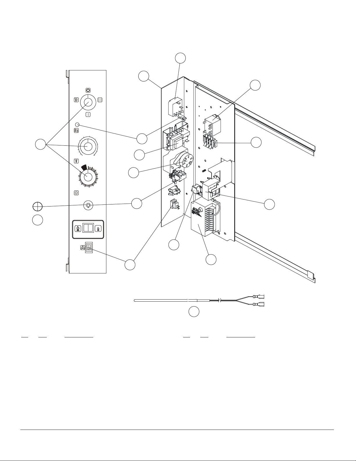
INFINITE CONTROL
120 VOLT FOR OVENS BUILT BEFORE 10/22/2003
4
16
OVEN OFF
12
14
COOL
DOWN
HIGH RATE DISABLED WITH LOW FAN
OVEN READY
0
7
1
25
3
0
5
1
00
5
3
2
130
7
5
2
5
1
0
1
0
2
0
0
9
0
1
7
0
60
55
50
45
80,000
BTU
ROAST
FROZEN
HEAVY LOAD
RAPI D COOK
DISCONNECT THIS PRODUCT FROM THE
POWER SUPPLY BEFORE OPENING THE
LIGHT OFF
5
3
5
0
°C
ON
OFF
190
0
LOW FAN
5
7
3
°F
THERMOSTAT
F
F
O
40
TIMER
GAS SHUTOFF
CONTROL MODULE
HIGH
FAN
2
1
0
4
0
0
2
4
2
3
5
0
4
5
0
25
4
0
7
5
0
0
5
5
2
0
5
7
2
0
5
5
0
9
2
0
5
10
15
20
25
30
35
60,000
BTU
BAKE
FRESH
LIGHT LOAD
STD. COOK
3
13
8
15
1
10
9
11
7
2
Ref. Part
No. No. Description
1 36546 Controller, Temperature, Solid State Modular
2 36506 Probe, Temperature, Solid State
3 18225 Timer, 60 Minute, 120V, 60 HZ
4 21068 Mode Selector Switch, 4 pos
5 36616 Knob, Replacement, all functions Qty 3
7 36376 Gas Switch, On/Off
8 18265 Indicator Light, Round, Red 28V
9 36121 Buzzer, 120V
10 20355 Transformer 115V to 24V
11 54725 Spark Box Nat & LP
Ref. Part
No. No. Description
12 36603 Relay, 120V
13 30662 Momentary Light Switch Kit
14 36651 Plug, for Light Switch
NOTE: For units without lights only, use
this plug piece.
15 36604 Terminal Block, for controller
30503 Terminal Block, interconnecting, at rear of unit
22301 Axial Fan, Low Velocity, 115V, 60 HZ (Qty 2)
36580 Harness, Rear Connecting
JULY 28, 2016 4 DFG-100 XCEL
Page 5
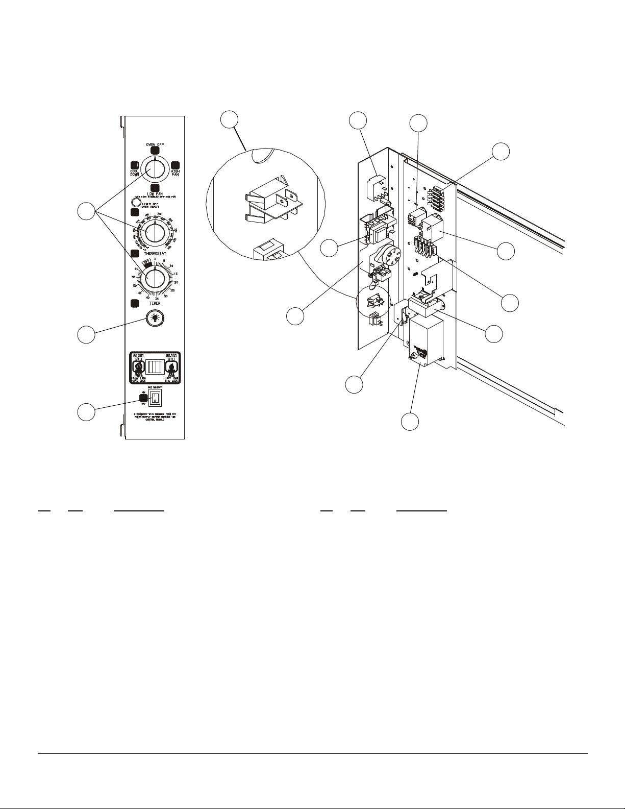
INFINITE CONTROL
24 VOLT FOR OVENS BUILT AFTER 10/22/2003
12
13
6
8
5
3
9
7
4
Note: orientation
shown is for ovens
built before 4/4/13.
Reverse for ovens
built after 4/4/13.
1
3
10
2
11
Ref. Part
No. No. Description
1 37317 Timer, 60 Min 24V
2 37489 Buzzer, 24V
3 37090 Harness, Module Inf
4 37058 High Fan Relay, 24 V
5 52781 Low Fan Relay, DPST 24V
37334 Harness, Innte Add-In
6 R8740 Rate Switch
37324 Module Assy, Innte 2 SP (Complete with
Probe)
Ref. Part
No. No. Description
7 36546 Controller, Temp, Before 4/4/13
56644 Controller, Temp 350º TDC, After 4/4/13
36506 Probe, Temp, Before 4/4/13
36720 Probe, Temp, After 4/4/13
8 21068 Switch, Mode 4 Position
9 36616 Knob, Control
10 20355 Transformer, 115V to 24V
11 54725 Control, Ignition Nat or LP
12 30662 Switch, Momentary Light
13 36376 Switch, Gas On/Off
JULY 28, 2016 5 DFG-100 XCEL
Page 6
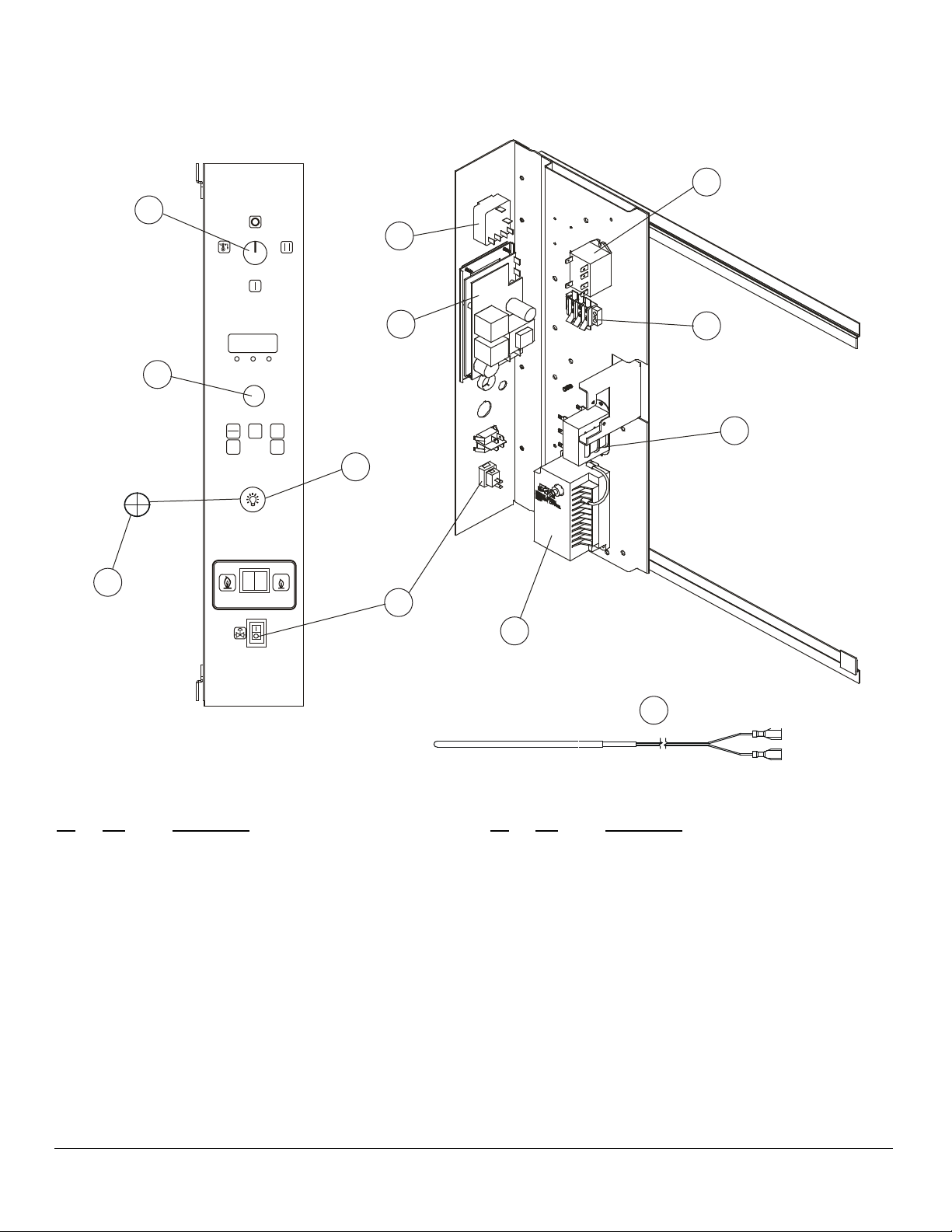
DIGITAL TIME & TEMPERATURE CONTROL
5 KEY DIGITAL - FOR OVENS BUILT BEFORE 10/22/2003
10
12
4
OVEN OFF
3
COOL
DOWN
HIGH RATE DISABLED WITH LOW FAN
HEAT PULSE HOLD
LOW FAN
HIGH
FAN
1
13
5
START
TEMP
TIME
STOP
HOLD
PULSE
8
11
80,000
BTU
ROAST
FROZEN
HEAVY LOAD
RAPID COOK
GAS SHUTOFF
ON
OFF
DISCONNECT THIS PRODUCT FROM THE
POWER SUPPLY BEFORE OPENING THE
CONTROL MODULE
60,000
BTU
BAKE
FRESH
LIGHT LOAD
STD. COOK
7
9
Ref. Part
No. No. Description
1 30658 Controller, Temperature, Solid State Digital
2 36506 Probe, Temperature, Solid State
3 21068 Mode Selector Switch, 4 pos
4 36616 Knob, Replacement, Mode
5 36617 Knob, Replacement, Adjust temperature
7 36376 Gas Switch, On/Off
8 20355 Transformer 115V to 24V
9 54725 Spark Box Nat & LP
10 36603 Relay, 120V
2
Ref. Part
No. No. Description
11 30662 Momentary Light Switch Kit
12 36651 Plug, for Light Switch
NOTE: For units without lights only, use this plug
piece.
13 36604 Terminal Block, for controller
30503 Terminal Block, interconnecting, at rear of unit
22301 Axial Fan, Low Velocity, 115V, 60 HZ (Qty 2)
36580 Harness, Rear Connecting
JULY 28, 2016 6 DFG-100 XCEL
Page 7

DIGITAL TIME & TEMPERATURE CONTROL
24 VOLT FOR OVENS BUILT AFTER 10/22/2003
6
3
1
2
1
Ref. Part
No. No. Description
1 37317 Timer, 60 Min 24V
2 37489 Buzzer, 24V
3 37090 Harness, Module Inf
4 37058 High Fan Relay, 24 V
5 52781 Low Fan Relay, DPST 24V
37334 Harness, Innte Add-In
6 R8740 Rate Switch
37306 Module Assy, Solid State Digital
36506 Temperature Probe
37983 Panel & Decal
JULY 28, 2016 7 DFG-100 XCEL
Page 8

CH PRO 3 CONTROL
14 KEYS - FOR OVENS BUILT BEFORE 10/22/2003
14
9
12
OVEN OFF
COOL
DOWN
4
HIGH RATE DISABLED WITH LOW FAN
LOW FAN
HIGH
FAN
3
1
HR/MIN
READY
HEAT
MIN/SEC
HOLD
TEMP
1
2 3
START PROG STOP
FAN
11
10
13
7
80,000
BTU
ROAST
FROZEN
HEAVY LOAD
RAPID COOK
GAS SHUTOFF
ON
OFF
DISCONNECT THIS PRODUCT FROM THE
POWER SUPPLY BEFORE OPENING THE
CONTROL MODULE
60,000
BTU
BAKE
FRESH
LIGHT LOAD
STD. COOK
6
8
2
Ref. Part
No. No. Description
1 37087 Controller, CH Pro 3
2 36720 Probe, Temperature, CH Pro 3
3 21068 Mode Selector Switch, 4 pos
4 36616 Knob, Replacement
6 36376 Gas Switch, On/Off
7 20355 Transformer 115V to 24V
8 54725 Spark Box Nat & LP
9 36603 Relay, 120V, Hi Speed
10 R3983 Relay, 120V, Low Speed
Ref. Part
No. No. Description
11 30662 Momentary Light Switch Kit
12 36651 Plug, for Light Switch
NOTE: For units without lights only, use this plug
piece.
13 36604 Terminal Block, for controller
30503 Terminal Block, interconnecting, at rear of unit
14 52879 Control Panel & Decal Assy
22301 Axial Fan, Low Velocity, 115V, 60 HZ (Qty 2)
JULY 28, 2016 8 DFG-100 XCEL
Page 9

CH PRO 3 CONTROL
24 VOLT FOR OVENS BUILT AFTER 10/22/2003
1
6
2
3
2
Ref. Part
No. No. Description
1 52781 Low Fan Relay, DPST 24VAC
2 37090 Harness, Control
3 37058 High Fan Relay, 24VAC
6 R8740 Rate Switch
JULY 28, 2016 9 DFG-100 XCEL
Page 10

IQ2 CONTROL
21 KEYS
11
OVEN
HEAT
OFF
ON
OFF
LOW
FAN
HOLD
PROG
GAS SHUTOFF
1
2
3
4
5
SHELF
1
SHELF
2
SHELF
3
COOL
DOWN
TOGGLE
CLEAR
ACTUAL
TEMP
SCAN
10
SHELF
SHELF
12
3
6
4
OVEN
ON
SET
TEMP
ENTER
80,000
BTU
60,000
BTU
PROGRAM
HIGH
FAN
5
7
8
6
7
8
9
4
5
1
9
10
13
2
Ref. Part
No. No. Description
1 37035 Controller, IQ2
2 36720 Probe, IQ2
3 19619 Rocker Switch, DPST, Black
4 36376 Gas Switch, On/Off
5 R8740 Rate Switch
6 56738 Relay, 24V Qty 2 per oven
7 36628 Relay, 24V, Qty 1 per oven
8 36604 Terminal Block, 3 pole
9 36700 Transformer, 120/240V to 24V Step Down
10 54725 Spark Box, Nat & LP
11 36403 Decal, IQ2, Before 7/20/2007
50829 Decal, IQ2, After 7/20/2007
22301 Axial Fan, Low Velocity, 115V, 60 HZ (Qty 2)
12 36680 Module Assy, IQ2 Controller (Less Controller)
13 30662 Light Switch
JULY 28, 2016 10 DFG-100 XCEL
Page 11

SMARTOUCH CONTROL
10
11
12
13
1
9
2
3
8
14
4
5
Ref. Part
No. No. Description
1 55950 Control, Programmed, Before 11/8/13
57738 Control, Programmed, After 11/8/13
2 52161 USB Cover
3 39781 Meat Probe Jack
39782 Meat Probe Jack Plug
56545 Meat Probe, 4", Dual Sensor
56546 Meat Probe, 6", Dual Sensor
4 R8740 Rate Switch
5 36376 Switch, Gas Shut-off
6 39688 Circuit Breaker 20A
7 55599 Relay, DPST, 24VDC
8 38604 Relay, DPDT, 24VDC
39343 Jumper
6
7
15
16
17
Ref. Part
No. No. Description
9 52647 USB Cable
10 53219 Speaker
11 53206 I/O Board, Before 11/8/13
57727 I/O Board, After 11/8/13
12 36755 Thermal Switch
13 36720 Probe, RTD, 1K
14 36700 Transformer, 120/240 to 24V
15 54604 DC Power Supply, 24V, 15W
16 52777 Varistor Assembly, 115V
17 54725 Ignition Control
54330 Communication Cable
JULY 28, 2016 11 DFG-100 XCEL
Page 12

HUMIDAIRE
5 KEYS
14
5
4
13
9
6
3
12
Ref. Part
No. No. Description
11
1
9
2
15
8
10
7
1 30658 Controller, temperature
2 20355 Transformer, 115V to 24V
3 30662 Momentary Light Switch Kit
4 21068 Switch, Rotary 4 Position
5 36616 Knob, Mode
6 36617 Knob, Adjust
7 36376 Switch, Gas On/Off
8 54725 Control, Ignition
9 37090 Harness, Digital
10 R8740 Switch, Rate
11 37058 High Fan Relay, 24 VAC
12 19014 Light, Indicator 28 VAC Amber
36853 Harness, Humidaire
13 36854 Timer, Preset Humidaire
14 52781 Relay, DPST 24V
15 30662 Pushbutton, Humidaire
37098 Harness, Rear Humidaire
37769 Harness, Jumper Probe
JULY 28, 2016 12 DFG-100 XCEL
Page 13

HUMIDAIRE COMPONENTS
1
3
2
1
4
5
6
4
7
Ref. Part
No. No. Description
36911 Regulator and Solenoid Assy 24VAC (includes everything pictured above)
1 M0959 Fitting, Compression 1/4 x 1/8
2 R10837 Valve, Solenoid
3 R10838 Coil, Solenoid 24VAC
4 18312 Nipple, Brass Hex 1/4 x 1.38
5 18410 Tee, Brass 11/16 x 1-9/16
6 36910 Regulator, Pressure
7 18309 Elbow, Brass 1/4 Pipe 90 DEG
18314 Thermal Switch, SPNO
32875 Tape, Gore-tex gasket, 3/4" (by the foot)
37215 Dam, Liner Bottom
18339 Cap, End
19086 Grommet, Rubber 5/8
19087 Grommet, Nylon Split
33488 Tube, Flex 1/4 x 12"
36909 Fitting, Compression
36913 Tube, Water Inject
4817 Clip, Thermostat Bulb
4
JULY 28, 2016 13 DFG-100 XCEL
Page 14

LINER
NOT REPLACEABLE
2
EXPLODED INTERIOR VIEW
5
3
Ref. Part
No. No. Description
1 55829 Burner Assy, In Shot NAT
1 56020 Burner Assy, In Shot LP
2 36420 Heat Deector Assy
3 33171 Blower Wheel, Natural Gas (Before 6/10/2007 and after 7/6/2009)
3 15853 Blower Wheel, Natural Gas (After 6/102007 and before 7/6/2009)
3 15853 Blower Wheel, Propane
33147 Wheel Puller
4 37453 Motor Mount & Panel Assy. (After 4/1/2004 and Before 6/11/2007)
5 37022 Motor, 115V, 1PH, 3/4 HP, 2 SP (After 4/1/2004)
57867 Motor, 115V, 1PH, 2 SP (Before 4/1/2004)
50681 Motor Mount Assy., (After 6/10/2007)
4
1
JULY 28, 2016 14 DFG-100 XCEL
Page 15

INTERIOR COMPONENTS & EXTERIOR VIEW
4
1
13
11
12
14
6
10
5
7
Ref. Part
No. No. Description
1 36437 Interior Bafe, Porcelain, Blower Wheel
Cover (Before 6/10/2007)
51673 Bafe Assembly (After 6/10/2007 and before
7/6/2009)
37006 Bafe Assembly (After 7/6/2009)
4 4342 Lamp, Qty 2 per oven
4922 Socket, for Lamp Qty 2 per oven
36435 Housing, for Socket & Lamp
5 18768 Racks, Each, Qty 5 per oven
38855 EZ Slide Rack
D0128 Bulb, Halogen, Qty 4 per oven, type G4
.16" between pins (Before 6/1/13)
57075 Bulb, Halogen, qty 4 per oven, type G5.3
.21" between pins (Before 6/1/13)
57075 Bulb, Halogen (After 6/1/13)
D0125 Bezel, Halogen Light
D0127 Gasket, Halogen Light
8
Ref. Part
No. No. Description
50192 Lens, Halogen Light
52946 24VDC, Power Supply
M3166 Fuse, power Supply
6 36900 Rack Support Kit, Set of 2
14 36620 Stops, Rack Each Qty 2 per oven
7 17361 Combustion Compartment Cover w/louvers
and security package
36431 Combustion Compartment Cover w/o louvers
and security package
38659 Crumb Pan Set (LR & RH)
8 55829 Burner Assy, In Shot NAT
8 56020 Burner Assy, In Shot LP
9 36512 Cover, Access Panel
10 22301 Axial Fan, Qty 1
11 36621 Bodytop, with opening for ue box
12 36407 Bodyside, RH
13 37205 Bodyside, LH
54422 Side Heat Shield, Right or Left
9
JULY 28, 2016 15 DFG-100 XCEL
Page 16

BURNER & PIPING, EXPLODED
1
6
10
5
3
Ref. Part
No. No. Description
1 55829 Burner Assy, In Shot NAT
1 56020 Burner Assy, In Shot LP
3 55811 Manifold Assy, After 4-3-13
4 38453 Ignitor Upgrade Kit Consists of Flame Sensor Probe and Ignitor Rod
4 39987 Flame Sensor Probe
4 38521 Ignitor, Spark Rod
19677 Flame Sensor Wire
5 33249 Flex Hose, for Manifold
6 1949 Nipple, Close 1/2 NPT, Before 4-3-13
10 16118 Reducer, 3/4 to 1/2", Before 4-3-13
50253 Elbow, 1/2" Flare x 1/2" NPT, After 4-3-13
11 36415 Orice, Main Burner Qty 4 per oven, Specify gas type & model) BLANK
36544 Orice, Main Burner Pre-Drilled NAT
36545 Orice, Main Burner Pre-Drilled LP
55648 Ignitor Wire
11
4
JULY 28, 2016 16 DFG-100 XCEL
Page 17

GAS VALVE ASSY
2
Ref. Part
No. No. Description
1 36608 Dual Gas Valve Assy, Nat.
2 36229 Flex Tubing, with ttings acts as thru pipe
1 38722 Dual Gas Valve, LP
38677 Conversion kit, Nat. to LP
38678 Conversion Kit, LP to Nat.
1
JULY 28, 2016 17 DFG-100 XCEL
Page 18

8
14
4
DOOR COMPONENTS
5
3
10
Right Hand Door -
Attached to unit
2
8
14
1
Left Hand Door
Left Hand Door
10
9
11
4
5
DOOR HINGE
COMPONENTS
6
9
13
7
8
Ref. Part
No. No. Description
37240 Door Assy Sld, RH
1 37241 Door Assy, Sld LH
2 37242 Door Assy, Gls RH
3 37243 Door Assy, Gls LH
9035 Window Tool, for installation and removal of window assy
4 9036 Window Assy., Drop In (10-1/8" x 17-1/8")
17558 Door Handle, Porc.
5 18081 Top Plate, Door Handle
6 90004 Bushings, Door Hinge (Set of 2)
7 16657 Sleeve, Upper Door Bushing
8 17557 Hinge Pin, Upper Door
9 17311 Center Trim, Door
10 36606 Pressure Lock
11 36876 Gasket Assy, Perimeter
12 36037 Lower Door Support Assy
13 35193 Microswitch, Door
14 16470 Nameplate
12
Side View,
Lower Door
Support Assy
6
JULY 28, 2016 18 DFG-100 XCEL
Page 19

LOWER DOOR SUPPORT COMPONENTS
2
1
Ref. Part
No. No. Description
1 36037 Lower Door Support Assy
NOTE: Lower Door Support Assy includes the hinge pins, arms, chain & turnbuckles, sprocket assys, cam assy, and
microswitch.
2 35193 Microswitch, Door
NOTE: If you need to replace the sprockets, chain & turnbuckle, or the hinge pin we strongly suggest ordering the e
tire lower door support. It will include all of these components and will greatly reduce your labor costs and
time invested.
JULY 28, 2016 19 DFG-100 XCEL
Page 20

ACCESSORIES
2
1
3
3
6
5
Ref. Part
No. No. Description
1 7839 Drafthood Assy., Direct Vent, S/S (6" dia.)
DFG100 Xcel Sgl
2 7840 Draft Diverter, Canopy Vent, S/S
DFG100 Xcel Sgl
21108 Drafthood Assy., Direct Vent, S/S (8" dia.)
DFG100 Xcel Dbl
20447 Draft Diverter, Canopy Vent, S/S
DFG100 Xcel Dbl
3 36687 Flue Connector Assy, 3 Piece
DFG100 Xcel Dbl
3 36686 Flue Box Single Oven DFG100 Xcel
31803 Clips, Stacking Double Oven
7 35048 Backpipe Assy, Dbl
21826 Installation Hose 36"
21242 Installation Hose 48"
6
7
4
Ref. Part
No. No. Description
37162 Bodyback, ALCT
36698 Backsheet
4 8600 Legs, 6" w/ Bolts, S/S Set of 4
5 8598 Legs, 25" w/ Bolts, S/S Set of 4
33196 Seismic Legs, 6", S/S Set of 4
92000 Studs, Leg Set of 4
7847 Bolts, Leg Set of 8
6 5779 Casters w/ Plate Set of 4 Dbl Oven
16002 Casters Set of 4 Sgl Oven Only
19528 Casters, Low Prole Set of 4 Dbl Oven
31013 Casters, Heavy Duty Low Prole
Set of 4 (Jarvis & Jarvis) Dbl Oven
* 6486 Open Stand w/ Feet, S/S DFG100
* 11416 Open Stand w/ Casters, S/S DFG100
JULY 28, 2016 20 DFG-100 XCEL
 Loading...