

Page 1

ELECTRIC CONVECTION INSTALLATION
FOURS A CONVECTION D’INSTALLATION
IMPORTANT
WARNING: IMPROPER INSTALLATION, ADJUSTMENT, ALTERATION, SERVICE OR MAINTENANCE CAN CAUSE
PROPERTY DAMAGE, INJURY OR DEATH. READ THE INSTALLATION, OPERATING AND MAINTENANCE INSTRUCTIONS THOROUGHLY BEFORE INSTALLING OR SERVICING THIS EQUIPMENT.
INSTRUCTIONS TO BE FOLLOWED IN THE EVENT THE USER SMELLS GAS MUST BE POSTED IN A PROMINENT
LOCATION. THIS INFORMATION MAY BE OBTAINED BY CONTACTING YOUR LOCAL GAS SUPPLIER.
FOR YOUR SAFETY Do not store or use gasoline or other ammable vapors or liquids in the vicinity of this or any other
appliance.
The information contained in this manual is important for the proper installation, use, and maintenance of this oven.
Adherence to these procedures and instructions will result in satisfactory baking results and long, trouble free service.
Please read this manual carefully and retain it for future reference.
Errors: Descriptive, typographic or pictorial errors are subject to correction. Specications are subject to change without
notice.
AVERTISSEMENT: UNE INSTALLATION, UN AJUSTEMENT, UNE ALTERATION, UN SERVICE OU UN ENTRETIEN
NON CONFORME AUX NORMES PEUT CAUSER DES DOMMAGES A LA PROPRIETE, DES BLESSURES OU LA
MORT. LISEZ ATTENTIVEMENT LES DIRECTIVES D’INSTALLATION, D’OPERATION ET D’ENTRETIEN AVANT DE
FAIRE L’INSTALLATION OU L’ENTRETIEN DE CET EQUIPEMENT.
LES INSTRUCTIONS A RESPECTER AU CAS OU L’UTILISATEUR PERQOIT UNE ODEUR DE GAZ DOIVENT ETRE
AFFCHEES DANS UN ENDROIT BIEN VISIBLE. VOUS POUVEZ VOUS LES PROCURER AUPRES DE VOTRE
FOURNISSEUR DE GAZ LOCAL.
AVERTISSEMENT Ne pas entreposer ni utiliser de l’essence ni d’autres vapeurs ou liquides inammables dans le voi-
sinage de cet appariel, ni de tout autre appareil.
Les informations donnees dans le present manuel sont importantes pour installer, utiliser et entretenir correctement ce
four. Le respect de ces instructions et procedures permettra d’obtenir de bons resultats de cuisson et une longue duree
de service sans problemes. Veuillez lire le present manuel et le conserver pour pouvoir vous y reporter a l’avenir.
Erreurs: Les erreurs de description, de typographie ou d’illustration font l’objet de corrections. Les caracteristiques sont
sujettes a modications sans preavis.
BLODGETT OVEN COMPANY
www.blodgett.com
44 Lakeside Avenue, Burlington, Vermont 05401 USA Telephone: (802) 658-6600 Fax: (802)864-0183
PN 54866 Rev D (3/14)
© 2014 - G.S. Blodgett Corporation
Page 2
DELIVERY AND LOCATION
DELIVERY AND INSPECTION
All Blodgett ovens are shipped in containers to prevent damage. Upon delivery of your new oven:
• Inspect the shipping container for external damage. Any evidence of damage should be noted on the delivery receipt
which must be signed by the driver.
• Uncrate the oven and check for internal damage. Carriers will accept claims for concealed damage if notied within
fteen days of delivery and the shipping container is retained for inspection.
The Blodgett Oven Company cannot assume responsibility for loss or damage suffered in transit. The carrier assumed full
responsibility for delivery in good order when the shipment was accepted. We are, however, prepared to assist you if ling
a claim is necessary.
OVEN LOCATION
The well planned and proper placement of your oven will result in long term operator convenience and satisfactory performance. The following clearances must be maintained between the oven and any combustible or non-combustible construc-
tion.
OVEN CLEARANCES
Model Right Side Left Side Back Bottom
CTB/CTBR 0” (0cm) 0” (0cm) 0” (0cm) 0” (0cm)
Mark V-100 1” (2.5cm) 1” (2.5cm) 1” (2.5cm) 0.5” (1.3cm)
Mark V-200 0.5” (1.3cm) 0.5” (1.3cm) 0.5” (1.3cm) 0.5” (1.3cm)
SHO-100-E 0” (0cm) 0” (0cm) 0” (0cm) 0.5” (1.3cm)
Zephaire-100-E 0” (0cm) 0” (0cm) 0” (0cm) 0.5” (1.3cm)
Zephaire-200-E 0.5” (1.3cm) 0.5” (1.3cm) 0.5” (1.3cm) 0.5” (1.3cm)
Mark V XCEL 0” (0cm) 0” (0cm) 0” (0cm) 0.5” (1.3cm)
12” (30cm) must be available on all oven sides and back for servicing.
Keep the oven area free and clear of all combustibles such as paper, cardboard, and ammable liquids and solvents.
Do not place the oven on a curb base or seal to a wall. This will restrict the ow of air and prevent proper ventilation result-
ing in damage to the oven.
Before making any utility connections to this oven, check the rating plate to be sure the oven specications are compatible
with the electrical services supplied for the oven.
1. Pull out control panel. The rating plate attached to the inside of the control compartment.
ELECTRIC CONVECTION OVENS 2 INSTALLATION
Page 3
OVEN ASSEMBLY
LEG ATTACHMENT
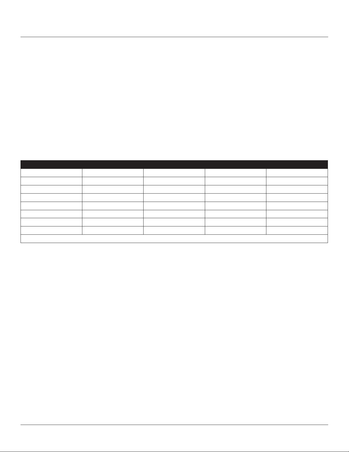
1. Push the oven onto a lift with the bottom of the oven down.
2. Align the threaded stud in each leg with the nut located inside each bottom corner of the oven frame. Turn the legs
clockwise and tighten to the nearest full turn.
3. Align the two leg plate holes in each leg with those in the oven bottom. Secure each leg using two 1/2” bolts.
NOTE: If using casters see CASTER ASSEMBLY before proceeding.
4. Level the oven by screwing the adjustable leg feet in or out as necessary.
6" (15 cm Legs Shown
Figure 1
CASTER ASSEMBLY
NOTE: Install the locking casters on the front of the oven. Install the non-locking casters on the back of the oven.
Casters for Single and Double Stacked Ovens:
1. Attach the legs as described.
2. Pry the adjustable feet out of the legs.
3. Insert one caster into each leg as shown. Tighten the lock nuts to secure the casters.
Low Prole Casters for Double Stacked Ovens:
1. Align the three holes in each caster assembly plate with those in the oven bottom. Secure each caster using three 1/2”
bolts.
Adjustable
Leg Foot
Caster Assembly
Figure 2
ELECTRIC CONVECTION OVENS 3 INSTALLATION
Page 4
OVEN ASSEMBLY
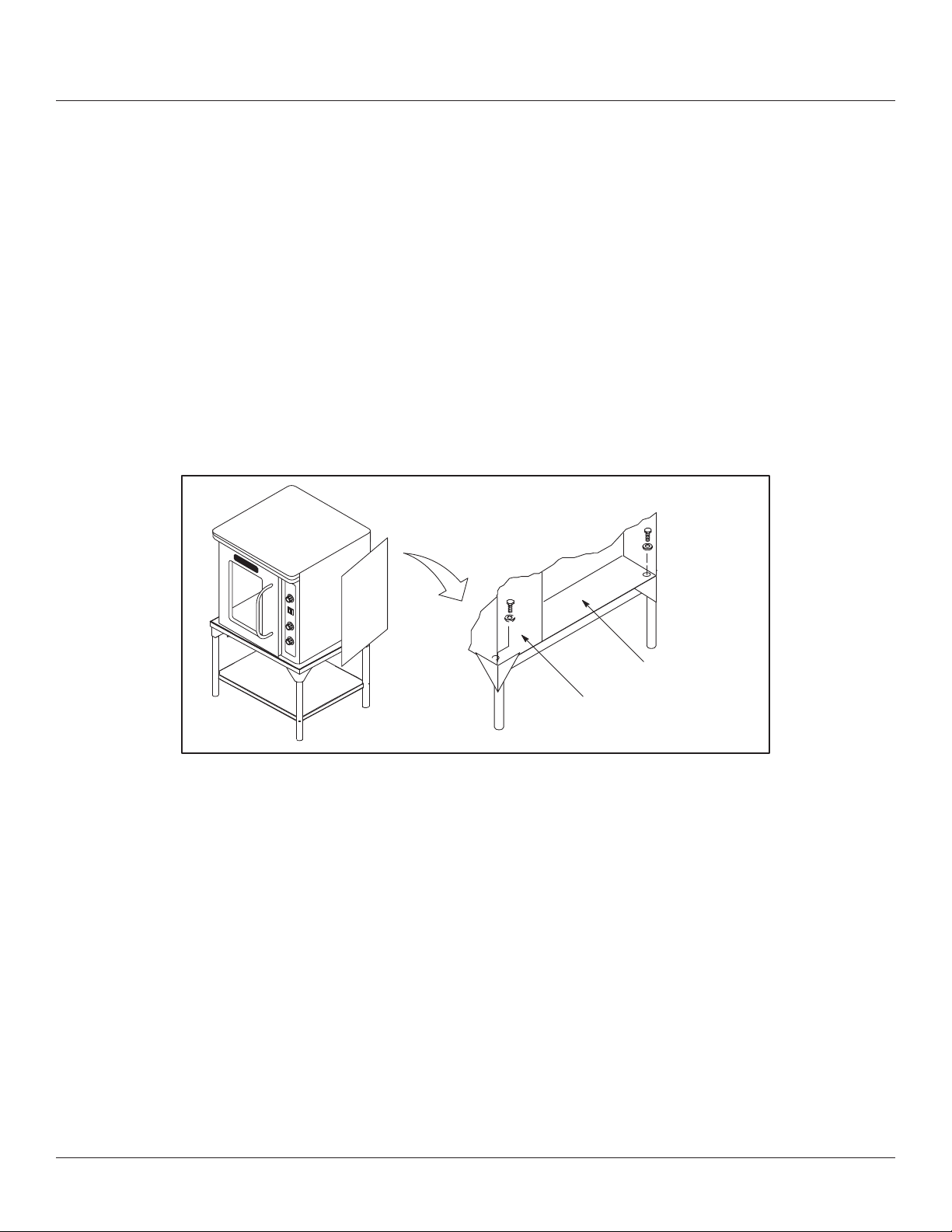
ASSEMBLY TO STAND - CTB ONLY SINGLE SECTION
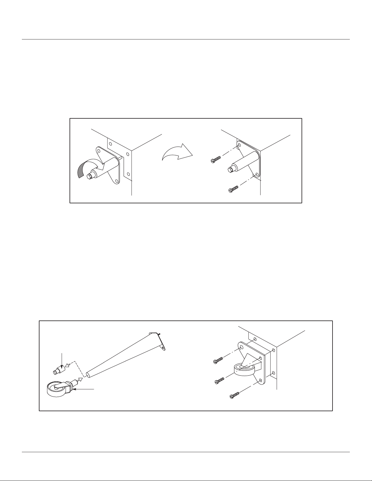
1. Place the assembled stand in the location where the oven is going to be used.
2. Remove the side control compartment cover and open the front control panel of a single oven (or lower section).
3. With a tool, punch out the knock-outs in the oven bottom near each corner on the control side.
4. Set the oven on the stand. Center it to the frame.
5. Align the front, and rear bolt holes of the oven with the bolt holes in the stand.
6. Insert a bolt and washer, from the top down through each of the 2 holes.
7. Place a nut and washer on each of the 2 bolts, and tighten securely.
8. Replace the oven’s side control compartment, and close the front control panel.
NOTE: For single section ovens only. For double stacked ovens step 8 will be completed once the ovens are stacked.
Figure 3
Motor
compartment
Control compartment
ELECTRIC CONVECTION OVENS 4 INSTALLATION
Page 5
OVEN ASSEMBLY
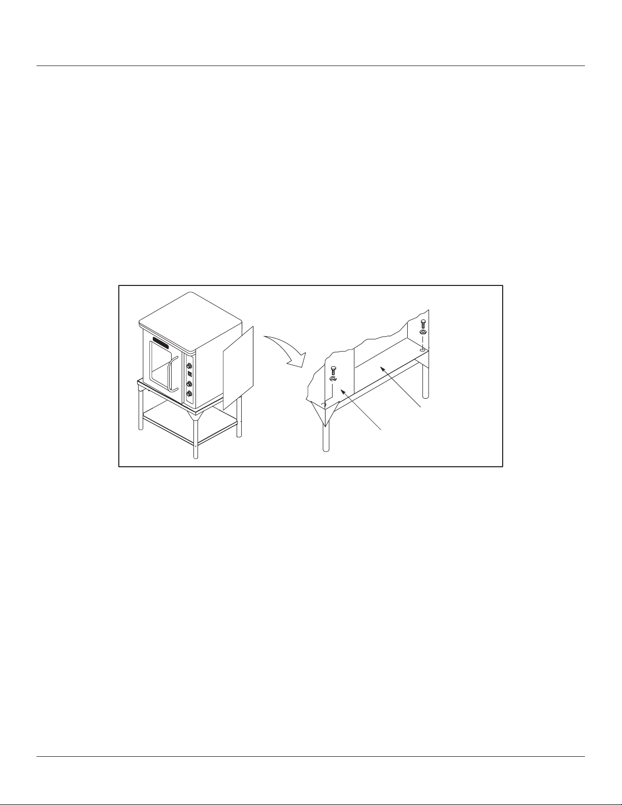
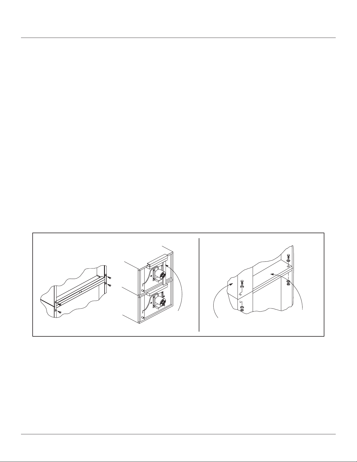
DOUBLE SECTION ASSEMBLY - FULL SIZE OVENS
1. Secure the short legs to the bottom sections as described.
2. Place the upper section in position on top of the lower oven.
3. Attach the stacking brackets using the remaining 5/16” bolts shipped with the ovens.
4. Attach the ue connector.
DOUBLE SECTION - CTB
1. Assemble the lower section to the stand as described. DO NOT replace the side control compartment or close the front
control panel.
2. With a tool, punch out the knock-outs in the oven top of the lower oven.
3. Remove the side control compartment cover and open the front control panel of the upper oven.
4. With a tool, punch out the knock-outs in the bottom of the upper oven near each corner.
5. Set the upper oven on the lower oven.
6. Align the front, and rear bolt holes of the upper oven with the bolt holes in the bottom oven.
7. Insert a bolt and washer, from the top down through each of the 2 holes.
8. Place a nut and washer on each of the 2 bolts, and tighten securely.
9. Replace the control compartment cover, and close the front control panel on both of the ovens.
Full Size Oven
Flue
Connector
CTB
Control
compartment
Figure 4
OVEN LEVELING
After assembly, the oven should be leveled and moved to the operating location.
1. The oven can be leveled by adjusting the feet or casters located on the bottom of each leg.
Motor
compartment
ELECTRIC CONVECTION OVENS 5 INSTALLATION
Page 6
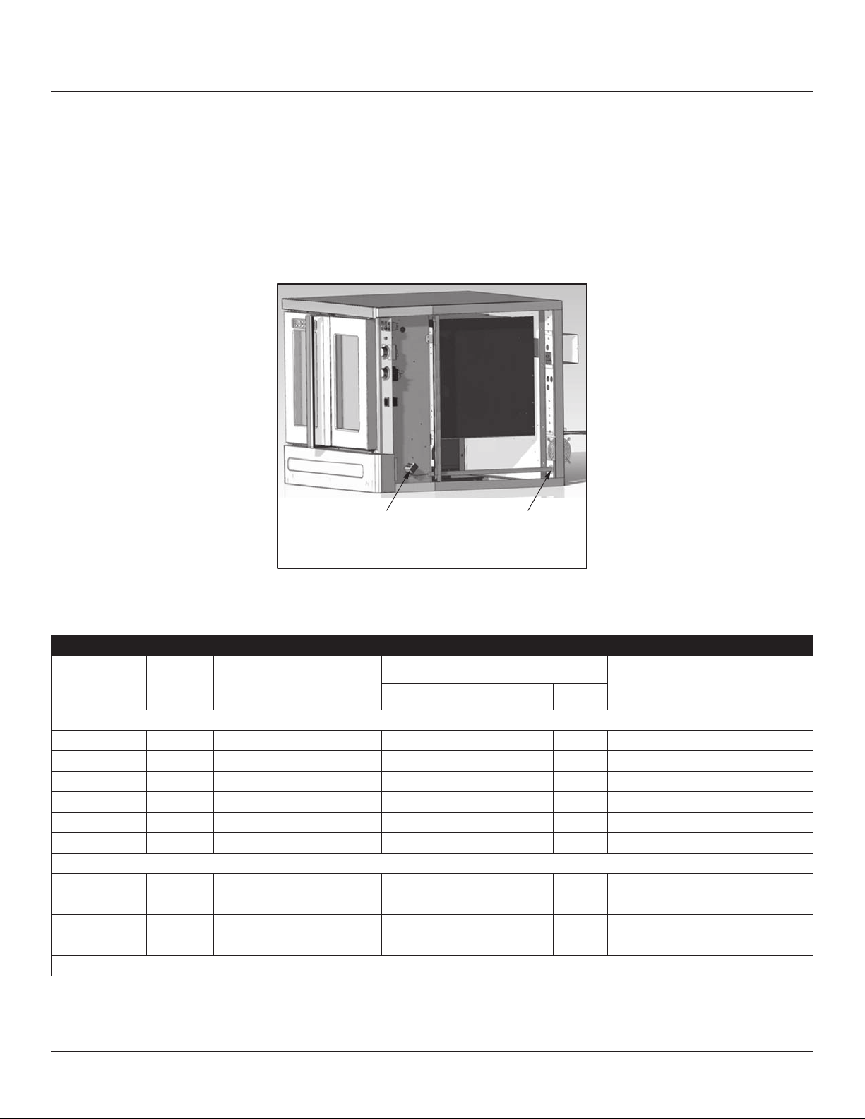
UTILITY CONNECTION
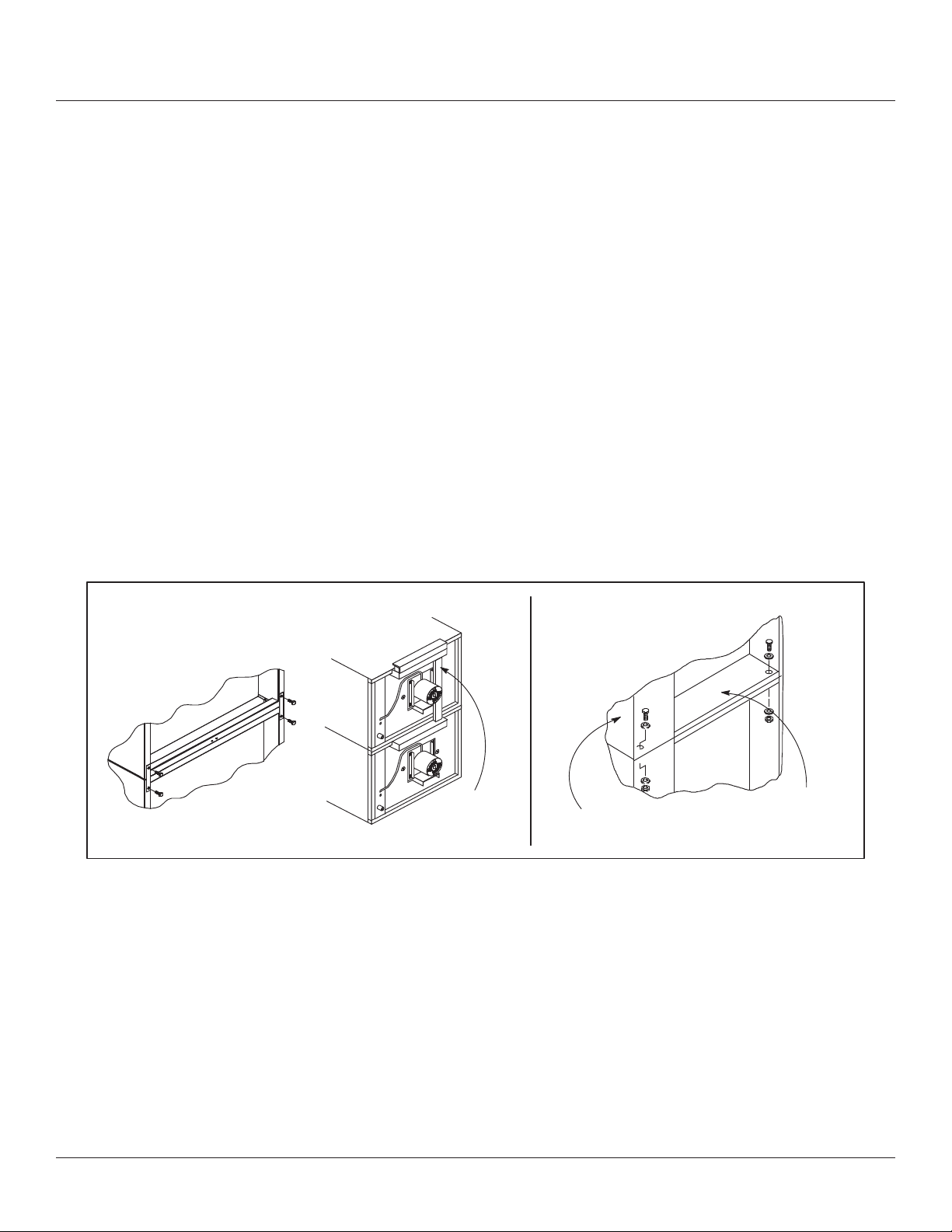
ELECTRICAL CONNECTION - ALL UNITS EXCEPT MARK V XCEL
Wiring diagrams are located in the control compartment and on the back of the oven. Ovens are supplied for operation in
several voltage choices, single or three phase grounded circuits. The electric motor, indicator lights and related switches are
connected the one power source supplied to the oven.
The supply conduit enters through the rear of the oven and electrical block secured to the perforated panel at the back of
the control compartment.
THE BLODGETT OVEN COMPANY CANNOT ASSUME RESPONSIBILITY FOR LOSS OR DAMAGE SUFFERED AS A
RESULT OF IMPROPER INSTALLATION.
Connect wires to
terminal block
Run supply line through
the knock-out
Figure 5
FULL SIZE OVENS
KW
HZ
VOLTAGE PHASE
MAX LOAD (AMPS ELECTRICAL
L1 L2 L2 N
CONNECTION
(MINIMUM SIZE)*
U.S. and Canadian installations
11.0 60 208 1 51 — 51 — 6 AWG
11.0 60 208 3 31 29 29 — 8 AWG
11.0 60 220-240 1 44 — 44 — 6 AWG
11.0 60 220-240 3 26 24 24 — 8 AWG
11.0 60 440 3 15 14 14 — 12 AWG
11.0 60 480 3 14 13 13 — 12 AWG
General Export installations
11.0 50 220-240 1 48 — — 48 Size per local code
11.0 50 220/380 3 18 15 15 3 Size per local code
11.0 50 240/415 3 18 14 14 4 Size per local code
11.0 50 230/400 3 18 15 15 3 Size per local code
NOTE: *Electric connection wiring is sized for 90ºC copper wire at 125% of rated input.
ELECTRIC CONVECTION OVENS 6 INSTALLATION
Page 7

UTILITY CONNECTION
CTB & CTBR
VOLTAGE
60 HZ
208 5.6 1 27 — 27 — 8
220-240 5.6 1 24 — 24 — 8
50 HZ
220-240 5.6 1 24 — — 24 Size per local codes
240/415 5.6 3 11 0 9 3 Size per local codes
230/400 5.6 3 11 0 10 1 Size per local codes
* Electric connection wiring is sized for 90ºC copper wire at 125% of rated input.
KW
5.6 3 24 12 15 — 10
6.8 1 33 — 33 — 6
6.8 3 20 18 19 — 10
8.0 1 35 — 35 — 6
8.0 3 22 20 21 — 10
5.6 3 21 11 14 — 10
6.8 1 28 — 28 — 6
6.8 3 18 16 17 — 10
8.0 1 32 — 32 — 6
8.0 3 20 18 19 — 10
6.8 1 28 — 28 —
8.0 1 35 — — 35
6.8 3 11 9 9
8.0 3 13 11 11 2
6.8 3 11 9 9
8.0 3 13 11 11 2
PHASE
MAX LOAD (AMPS) ELECTRICAL CONNECTION
L1 L2 L2 N
AWG*
NOTE: Double units can have phase loads partially equalized by matching lines during hook-up. Otherwise, CTB-Double
or CTBR-Double load ratings are twice the above data.
ELECTRIC CONVECTION OVENS 7 INSTALLATION
Page 8

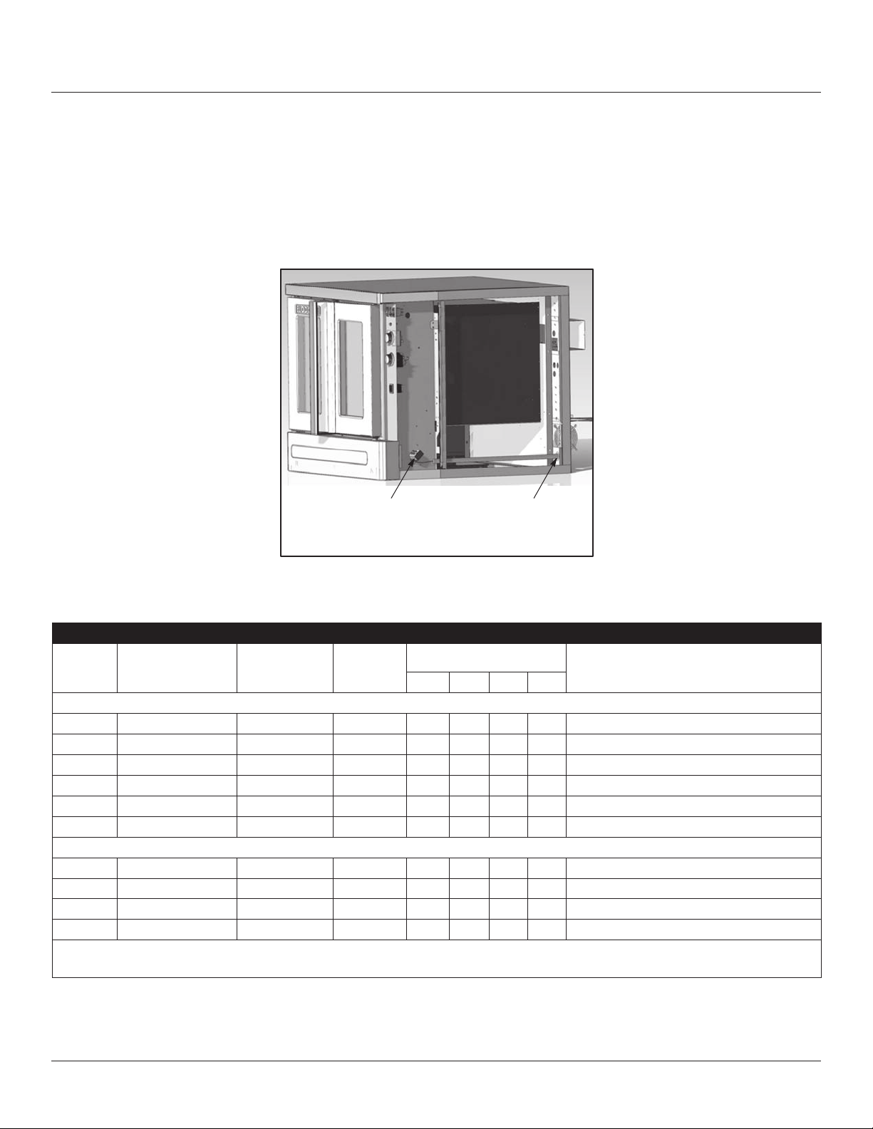
UTILITY CONNECTION
ELECTRICAL CONNECTION - MARK V XCEL
Wiring diagrams are located in the control compartment and on the back of the oven.
The electric motor, indicator lights and related switches are connected to the oven as follows:
1. Remove the bottom trim and control panel covers. Slide the control panel forward.
2. Connect the supply conduit to the wire duct located in the lower left hand corner on the back of the oven.
3. Run the supply wires through the duct to the front of the oven.
4. Connect the supply wires to top of right contactor in the control compartment at the lower right corner of the oven.
5. Reinstall the bottom trim and control panel covers.
NOTE: To prevent damage there is no power to the heating elements when the blower is not operating.
THE BLODGETT OVEN COMPANY CANNOT ASSUME RESPONSIBILITY FOR LOSS OR DAMAGE SUFFERED AS A
RESULT OF IMPROPER INSTALLATION.
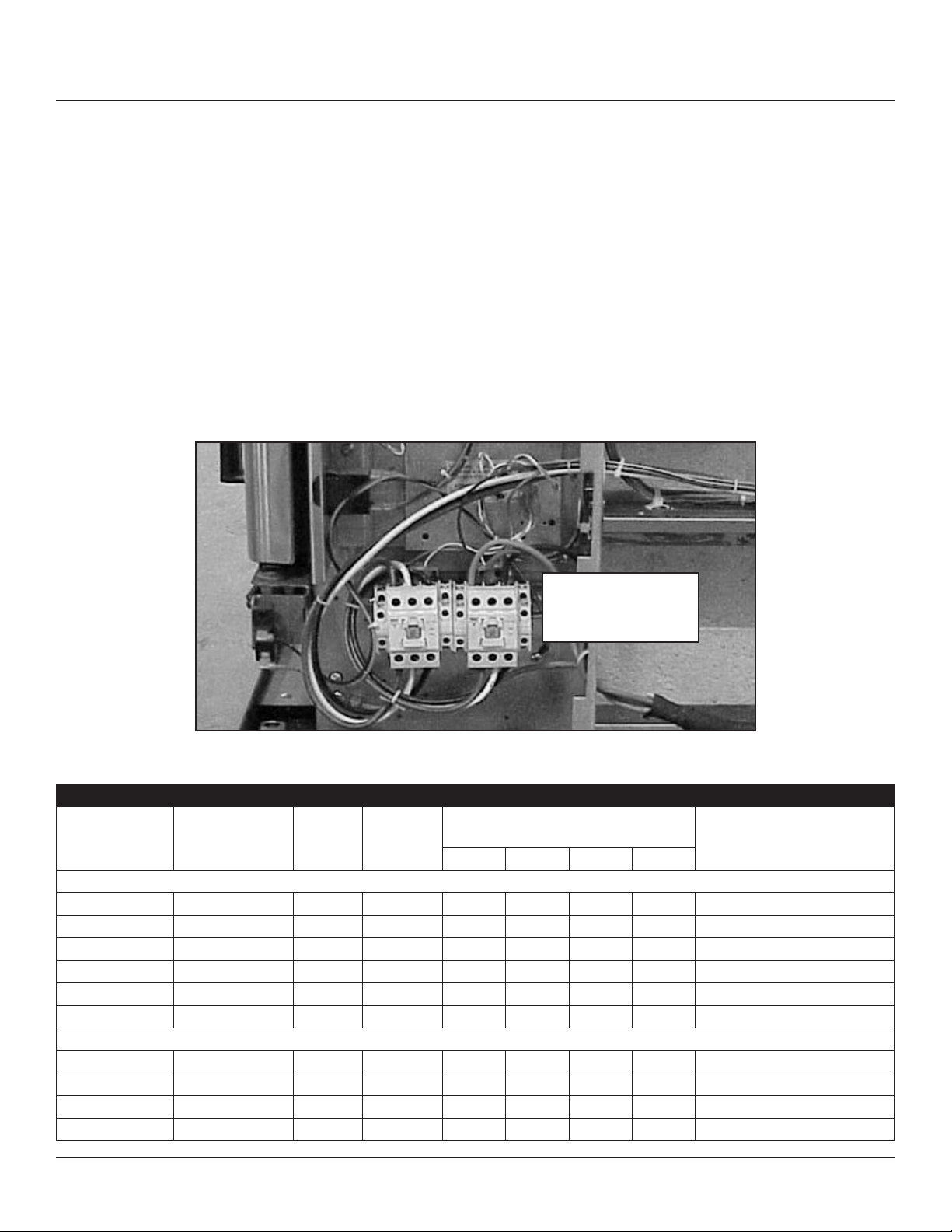
Install incoming
power on this
contactor
Figure 6
MARK V XCEL
VOLTAGE
HZ
KW
PHASE
MAX LOAD (AMPS
L1 L2 L3 N
MOTOR
U.S. and Canadian installations
208 60 11.0 1 53 — 53 — 6 AWG
208 60 11.0 3 33 28 33 — 8 AWG
220-240 60 11.0 1 50 — 50 — 6 AWG
220-240 60 11.0 3 28 23 28 — 8 AWG
440 60 11.0 3 16 13 16 — 12 AWG
480 60 11.0 3 15 12 15 — 12 AWG
General Export installations
220-240 50 11.0 1 50 — 50 — Size per local code
240/415 50 11.0 3 19 14 14 5 Size per local code
220/380 50 11.0 3 17 15 15 4 Size per local code
230/400 50 11.0 3 19 14 14 5 Size per local code
ELECTRIC CONVECTION OVENS 8 INSTALLATION
Page 9

INITIAL STARTUP
ADJUSTMENTS ASSOCIATED WITH INITIAL INSTALLATION
Each oven, and its component parts, have been thoroughly tested and inspected prior to shipment. However, it is often
necessary to further test or adjust the oven as part of a normal and proper installation. These adjustments are the responsibility of the installer, or dealer. Since these adjustments are not considered defects in material or workmanship, they are
not covered by the Original Equipment Warranty. They include, but are not limited to:
• calibration of the thermostat
• adjustment of the doors
• leveling
• tightening of fasteners.
No installation should be considered complete without proper inspection, and if necessary, adjustment by qualied installa-
tion or service personnel.
ELECTRIC CONVECTION OVENS 9 INSTALLATION
Page 10

LIVRAISON ET IMPLANTATION
LIVRAISON ET INSPECTION
Tous les fours sont expedies en conteneurs. A la reception de votre four Blodgett vous devez:
• Verier que les emballages ne sont pas abimes. Toute defection dans l’emballage doit etre notee sur l’accuse de
reception de la marchandise; celui-ci doit etre signe par le chauffeur.
• Sortir le four de son emballage et verier son bon etat. Les transporteurs n’acceptent les reclamations et plaintes que
si elles sont faites dans les quinze jours qui suivent la livraison et si l’emballage a ete conserve an d’etre inspecte.
La Blodgett Oven Co., n’est pas responsable des degats subis pendant le transport. Le transporteur est seul responsable
de la livraison du materiel en bon etat lorsque l’expedition a ete acceptee. Neanmoins, nous sommes a votre disposition
pour vous aider a composer votre dossier de reclamation.
IMPLANTATION DU FOUR
L’implantation correcte et bien etudiee du four sera a l’avantage a long terme de l’operateur et permettra d’obtenir un rendement satisfaisant. Les espaces de degagement ci-dessous doivent etre prevus entre le four et toute construction combus-
tible ou non.
DEGAGEMENTS DE FOUR
Mod le Cote droit Cote gauche Arri re du four Dessous du four
CTB/CTBR 0” (0cm) 0” (0cm) 0” (0cm) 0” (0cm)
Mark V-100 1” (2.5cm) 1” (2.5cm) 1” (2.5cm) 0.5” (1.3cm)
Mark V-200 0.5” (1.3cm) 0.5” (1.3cm) 0.5” (1.3cm) 0.5” (1.3cm)
SHO-100-E 0” (0cm) 0” (0cm) 0” (0cm) 0.5” (1.3cm)
Zephaire-100-E 0” (0cm) 0” (0cm) 0” (0cm) 0.5” (1.3cm)
Zephaire-200-E 0.5” (1.3cm) 0.5” (1.3cm) 0.5” (1.3cm) 0.5” (1.3cm)
Mark V XCEL 0” (0cm) 0” (0cm) 0” (0cm) 0.5” (1.3cm)
12” (30cm) doit etre disponible sur tous les cotes et dos de four pour l’entretien.
Maintenez la zone du four libre et degagee de tous materiaux combustibles tels que le papier, le carton, ainsi que les liquides et solvants inammables.
Ne pas mettre le four sur une base courbee ni le sceller au mur an d’eviter de limiter le debit d’air et d’empecher ainsi une
ventilation appropriee.
Avant de raccorder le four aux prises des services publics, verier la plaque signaletique an de s’assurer que les specications du four soient compatibles avec les services electriques fournis a ce dernier.
1. La plaque signaletique est situee au dessous du four.
FOURS A CONVECTION 10 D’INSTALLATION
Page 11

MONTAGE DU FOUR
ASSEMBLAGE DES PIEDS
1. Pousser le four, couche sur le dos, sur un elevateur.
2. Alignez le goujon lete du pied sur le trou de vis prevu dans le coin avant du fond de caisse. Vissez le pied, dans le sens
des aiguilles d’une montre, jusqu’au dernier tour complet possible.
3. Alignez les deux orices de la plaque du pied sur les trous prevus au bas du four. Fixez le pied a l’aide de deux boulons
de 12.7 mm (1/2 po).
REMARQUE: Si des roulettes sont utilisees, voir MONTAGE DES ROULETTES avant de continuer.
4. Si necessaire, mettez le four de niveau en vissant ou en devissant la vis de niveau des pieds reglables.
Illustre : pieds de 15 cm (6”)
Figure 7
MONTAGE DES ROULETTES
REMARQUE: Installer les roulettes a frein sur le devant du four. Installer les roulettes sans frein a l’arriere.
Roulettes pour four simple ou pour four superposes :
1. Placer les pieds comme decrit.
2. Desserrer l’ecrou de blocage des embouts au bas de chaque pied reglable. Retirer les embouts.
3. Inserer une roulette dans chaque pied, comme illustre. Serrer les ecrous de blocage pour xer les roulettes.
Roulettes de bas prole pour deux fours superposes :
1. Aligner les trois trous dans chaque plaque de l’ensemble de roulette avec les trous dans le fond du four. Fixer chaque
roulette a l’aide de trois boulons de 12.7 mm (1/2 po).
Embouts de pied
ajustables
Ensemble de roulette
Figure 8
FOURS A CONVECTION 11 D’INSTALLATION
Page 12
MONTAGE DU FOUR
ASSEMBLAGE DU FOUR SUR LE SOCLE - CTB SEULEMENT SECTION SIMPLE
1. Placez le bati assemble a l’endroit denitif ou sera utilise le four.
2. Retirez le couvercle du compartiment lateral de commande et ouvrez le panneau de commande avant du four (ou du
four inferieur).
3. Au moyen d’un outil, detachez les rondelles amovibles situees pres de chaque coin du fond du four.
4. Placez le four sur le bati. Centrez-le sur le bati.
5. Alignez les trous de boulon avant et arriere du four avec les trous de boulon du bati.
6. Inserez, du haut vers le bas, un boulon et une rondelle dans chacun des 2 trous.
7. Posez un ecrou et une rondelle sur chacun des 2 boulons et serrez a fond.
8. Remettez le couvercle du compartiment lateral en place et refermez le panneau de commande avant.
REMARQUE: Pour les fours simples seulement. Dans le cas de fours doubles superposes, effectuez l’etape 8 une fois
les deux fours superposes.
Figure 9
Compartiment de
moteur
Compartiment de
commandez
FOURS A CONVECTION 12 D’INSTALLATION
Page 13
MONTAGE DU FOUR
MONTAGE DE LA SECTION DOUBLE - FOURS EN TAILLE RÉELLE
1. Fixez les pieds de courte longueur au bas de la section inferieure comme decrit.
2. Posez la section superieure par-dessus la section inferieure.
3. Fixez les ferrures de montage superpose au moyen des autres boulons de 5/16 po expedies avec les fours.
4. Raccordez le connecteur de carneau.
MONTAGE DE LA SECTION DOUBLE - CTB
1. Assemblez la section inferieure du bati, tel que decrit. NE REFERMEZ PAS le couvercle du compartiment lateral ni le
panneau de commande avant.
2. Au moyen d’un outil, detachez les rondelles amovibles situees sommet du four inferieur.
3. Retirez le couvercle du compartiment lateral des commandes et ouvrez le panneau de commande avant du four super-
ieur.
4. Au moyen d’un outil, detachez les rondelles amovibles situees pres de chaque coin du fond du four superieur.
5. Mettez le four superieur sur le four inferieur.
6. Alignez les trous de boulon avant et arriere du four superieur avec les trous de boulon du four inferieur.
7. Inserez, du haut vers le bas, un boulon et une rondelle dans chacun des 2 trous.
8. Posez un ecrou et une rondelle sur chacun des 2 boulons et serrez a fond.
9. Remettez le couvercle du compartiment de commande en place et refermez le panneau de commande avant des deux
fours.
Fours en taille réelle
Le Connecteur
CTB
Compartiment de
commandez
Compartiment de
moteur
Figure 10
MISE A NIVEAU DU FOUR
Apres assemblage le four doit etre mis a niveau et installe a son emplacement d’utilisation.
1. Le four peut etre mis a niveau en ajustant les vis de mise a niveau ou les roulettes en bas de chaque pied.
FOURS A CONVECTION 13 D’INSTALLATION
Page 14
BRANCHEMENT D’UTILITE
RACCORDEMENT ELECTRIQUE - TOUTES LES UNITÉS SAUF MARK V XCEL
Les diagrammes de cablage se trouvent dans le coffret de commande et a l’arriere du four. Les fours sont disponibles pour
operation dans plusieurs choix de voltages, de circuits mis a la terre monophases ou triphases. Le moteur electrique, les
voyants lumineux et les interrupteurs connexes sont raccordes au four comme suit:
Le conduit du l’arriere du compartiment de commande.
LA SOCIETE BLODGETT NE SAURAIT ETRE TENUE POUR RESPONSABLE DES PERTES OU DOMMAGES SUBI PAR
SUITE DE L’INSTALLATION INCORRECTE DE FOURS.
Connect wires to terminal
block
Amener la ligne
d’alimentation à travers le
disque défonçable
Figure 11
FOURS EN TAILLE RÉELLE
KW
FREQUENCE
TENSION PHASE
AMP RES CONNEXION ELECTRIQ E
L1 L2 L2 N
(CALIBRE MINIMUM)*
Installation E-U et Canada
11.0 60 208 1 51 — 51 — 6 AWG
11.0 60 208 3 31 29 29 — 8 AWG
11.0 60 220-240 1 44 — 44 — 6 AWG
11.0 60 220-240 3 26 24 24 — 8 AWG
11.0 60 440 3 15 14 14 — 12 AWG
11.0 60 480 3 14 13 13 — 12 AWG
Installation a l’export
11.0 50 220-240 1 48 — — 48 Calibre suivant code local
11.0 50 220/380 3 18 15 15 3 Calibre suivant code local
11.0 50 240/415 3 18 14 14 4 Calibre suivant code local
11.0 50 230/400 3 18 15 15 3 Calibre suivant code local
REMARQUE: *La dimension du cablage des connexions electriques est determinee pour les ls de cuivre de 90ºC
a 125 % de la puissance d’entree nominale.
FOURS A CONVECTION 14 D’INSTALLATION
Page 15

BRANCHEMENT D’UTILITE
CARACTÉRISTIQUES TECHNIQUES- CTB ET CTBR
TENSION
FRÉQUENCE 60 HZ
208 5.6 1 27 — 27 — 8
220-240 5.6 1 24 — 24 — 8
FRÉQUENCE 50 HZ
220-240 5.6 1 24 — — 24 Calibre suivant code local
240/415 5.6 3 11 0 9 3 Calibre suivant code local
230/400 5.6 3 11 0 10 1 Calibre suivant code local
REMARQUE: *La dimension du câblage des connexions électriques est déterminée pour les ls de cuivre de 90 °C à 125
% de la puissance d’entrée nominale.
KW
5.6 3 24 12 15 — 10
6.8 1 33 — 33 — 6
6.8 3 20 18 19 — 10
8.0 1 35 — 35 — 6
8.0 3 22 20 21 — 10
5.6 3 21 11 14 — 10
6.8 1 28 — 28 — 6
6.8 3 18 16 17 — 10
8.0 1 32 — 32 — 6
8.0 3 20 18 19 — 10
6.8 1 28 — 28 —
8.0 1 35 — — 35
6.8 3 11 9 9
8.0 3 13 11 11 2
6.8 3 11 9 9
8.0 3 13 11 11 2
PHASE
CHARGE MAXIMALE (AMPÈRES) CONNEXION ÉLECTRIQUE
L1 L2 L2 N
(CALIBRE MINIMUM)*
REMARQUE: Les charges de phase des unités doubles peuvent être partiellement mises en équilibre en alignant les
lignes lors du raccordement. Sinon, les exigences de charge électrique des modèles de fours superposés
CTB-double ou CTBR-double sont égales à deux fois les données indiquées ci-dessus.
FOURS A CONVECTION 15 D’INSTALLATION
Page 16
BRANCHEMENT D’UTILITE
RACCORDEMENT ELECTRIQUE - MARK V XCEL
Les diagrammes de cablage se trouvent dans le coffret de commande et a l’arriere du four.
Le moteur electrique, les voyants lumineux et les interrupteurs connexes sont raccordes au four comme suit:
1. Retirer la garniture inferieure et les couvercles du panneau de commande, puis glisser le panneau vers l’avant.
2. Raccorder le conduit d’alimentation a la gaine de ls situee dans le coin gauche inferieur, derriere le four.
3. Acheminer les ls d’alimentation a travers la gaine jusqu’au devant du four.
4. Raccorder les ls d’alimentation a la partie superieure du contacteur droit a l’interieur du compartiment de commande
situe dans le coin droit inferieur du four.
5. Reinstaller le garniture inferieure et les couvercles du panneau de commande.
REMARQUE: An de prevenir les dommages, les elements chauffants sont hors tension lorsque le ventilateur soufant
ne fonctionne pas.
LA SOCIETE BLODGETT NE SAURAIT ETRE TENUE POUR RESPONSABLE DES PERTES OU DOMMAGES SUBI PAR
SUITE DE L’INSTALLATION INCORRECTE DE FOURS.
Installer la prise
d’alimentation d’entree
sur ce contacteur
Figure 12
SPÉCIFICATIONS ÉLECTRIQUES (PAR SECTION DE FOUR) - MKV1XL/AA
TENSION
FRÉQUENCE
KW
PHASE
CHARGE MAXIMALE
(AMPÈRES)
MOTEUR
L1 L2 L3 N
Installation É-U et Canada
208 60 11.0 1 53 — 53 — 6 AWG
208 60 11.0 3 33 28 33 — 8 AWG
220-240 60 11.0 1 50 — 50 — 6 AWG
220-240 60 11.0 3 28 23 28 — 8 AWG
440 60 11.0 3 16 13 16 — 12 AWG
480 60 11.0 3 15 12 15 — 12 AWG
Installation à l’export
220-240 50 11.0 1 50 — 50 — Calibre suivant code local
240/415 50 11.0 3 19 14 14 5 Calibre suivant code local
220/380 50 11.0 3 17 15 15 4 Calibre suivant code local
230/400 50 11.0 3 19 14 14 5 Calibre suivant code local
FOURS A CONVECTION 16 D’INSTALLATION
Page 17

MISE EN MARCHE INITIALE
REGLAGES A FAIRE LORS DE L’INSTALLATION INITIALE
Chaque four ainsi que ses composants ont ete soigneusement testes et inspectes avant d’etre expedies. Ce pendant, il est
bien souvent necessaire de faire des verications et des reglages sur place au moment de l’installation initiale. Ceci est un
procede normal. De tels reglages sont sous la responsabilite du vendeur ou de l’installateur et ne sont pas imputables a des
defauts de fabrication ou de materiau. Par consequent, ces reglages ne sont pas couverts par la garantie de l’equipment
d’origine. Ces reglages comprennent, sans s’y limiter:
• le calibrage du thermostat
• le reglage des portes
• reglage du bruleur
• la mise de niveau
• la verication de la pression du gaz
• le serrage des boulons
On ne peut considerer une installation achevee tant qu’un personnel qualie n’a pas procede a sa verication complete et
fait les reglages necessaires s’il en est besoin.
FOURS A CONVECTION 17 D’INSTALLATION
 Loading...