

Page 1

CTBR-AP
KFC ALL PURPOSE HALF-SIZE
ELECTRIC CONVECTION OVEN
INSTALLATION - OPERATION - MAINTENANCE
BLODGETT OVEN COMPANY
www.blodgett.com
44 Lakeside Avenue, Burlington, Vermont 05401 USA Telephone: (802) 658-6600 Fax: (802)864-0183
PN 34532 Rev H (10/12)
© 2012 - G.S. Blodgett Corporation
Page 2

Your Service Agency’s Address:
Model
Serial number
Oven installed by
Installation checked by
Page 3

IMPORTANT
TABLE OF CONTENTS
WARNING: Improper installation, adjustment, alternation,
service or maintenance can
cause property damage, injury or death. Read the instllation, operation and maintenance instructions thoroughly
before installing or servicing
this equipment.
FOR YOUR SAFETY
Do not store or use gasoline or
other ammable vapors or liquids in the vicinity of this or any
other appliance.
The information contained in this
manual is important for the proper installation, use, and maintenance of this oven. Adherence
to these procedures and instructions will result in satisfactory
baking results and long, trouble free service. Please read
this manual carefully and retain
it for future reference.
ERRORS: Descriptive, typographic or pictorial errors are
subject to correction. Specications are subject to change
without notice.
INSTALLATION
Oven Description and Specications ....................................... 2
Utility Connections ....................................................... 3
Oven Assembly .......................................................... 4
Stand Assembly ...................................................... 4
Oven Assembly to Stand .............................................. 5
Double Section Assembly ............................................. 6
Ventilation .......................................................... 10
OPERATION
Safety Information ....................................................... 11
IQ VVC-208 Control ..................................................... 12
Component Description .............................................. 12
Oven Operational Test Procedure ..................................... 13
Recipe Review ...................................................... 13
View Temperature Setting ............................................ 13
Cool Down.......................................................... 13
Setback ............................................................ 14
Programming ....................................................... 14
Changing the Menu Strip ............................................. 14
Recipe Programming (1724) ......................................... 15
System Programming (6647) ......................................... 19
Product or Alarm Name Libraries (6647) ............................... 21
SCK Address (6647) ................................................. 23
MAINTENANCE
Cleaning and Preventative Maintenance .................................. 24
Page 4
Installation
Oven Description and Specications
Cooking in a convection oven differs from cooking in a
conventional deck or range oven since heated air is constantly recirculated over the product by a fan in an enclosed chamber. The moving air continually strips away
the layer of cool air surrounding the product, quickly allowing the heat to penetrate. The result is a high qual-
ity product, cooked at a lower temperature in a shorter
amount of time.
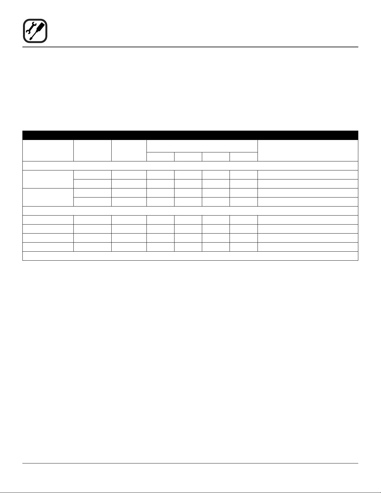
ELECTRICAL RATINGS
VOLTAGE
60 HZ
208 8.0 1 35 — 35 — 6
220-240 8.0 1 32 — 32 — 6
50 HZ
220-240 8.0 1 35 — — 35 Size per local codes
220/380 8.0 3 14 12 12 2 Size per local codes
240/415 8.0 3 13 11 11 2 Size per local codes
230/400 8.0 3 13 11 11 2 Size per local codes
* Electric connection wiring is sized for 90ºC copper wire at 125% of rated input.
KW
8.0 3 22 20 21 — 10
8.0 3 20 18 19 — 10
PHASE
MAX LOAD (AMPS) ELECTRICAL CONNECTION
L1 L2 L2 N
Blodgett convection ovens represent the latest advancement in energy efciency, reliability, and ease of operation. Heat normally lost, is recirculated within the cooking
chamber before being vented from the oven: resulting in
substantial reductions in energy consumption and enhanced oven performance.
AWG*
NOTE: Double units can have phase loads partially equalized by matching lines during hook-up. Otherwise, CTB-Double
or CTBR-Double load ratings are twice the above data.
2
Page 5

Installation
Utility Connections
THE INSTALLATION INSTRUCTIONS CONTAINED
HEREIN ARE FOR THE USE OF QUALIFIED INSTALLATION AND SERVICE PERSONNEL ONLY. INSTALLATION OR SERVICE BY OTHER THAN QUALIFIED
PERSONNEL MAY RESULT IN DAMAGE TO THE OVEN
AND/OR INJURY TO THE OPERATOR.
Qualied installation personnel are individuals, a rm,
a corporation, or a company which either in person or
through a representative are engaged in, and responsible
for:
• the installation of electrical wiring from the electric
meter, main control box or service outlet to the electric appliance.
Qualied installation personnel must be experienced in
such work, familiar with all precautions required, and have
complied with all requirements of state or local authorities
having jurisdiction.
U.S. and Canadian installations
All ovens, when installed, must be electrically grounded
in accordance with local codes, or in the absence of local codes, with the National Electrical Code, ANSI/NFPA
70-Latest Edition and/or Canadian National Electric Code
C22.2 as applicable.
The ventilation of this oven should be in accordance with
local codes. In the absence of local codes, refer to the
National ventilation code titled, “Standard for the Installa-
tion of Equipment for the Removal of Smoke and Grease
Laden Vapors from Commercial Cooking Equipment”,
NFPA-96-Latest Edition.
General export installations
Installation must conform with Local and National instal-
lation standards. Local installation codes and/or requirements may vary. If you have any questions regarding the
proper installation and/or operation of your Blodgett oven,
please contact your local distributor. If you do not have a
local distributor, please call the Blodgett Oven Company
at 0011-802-658-6600.
ELECTRICAL CONNECTION
WARNING!!
Before making any utility connections to this
oven, check the rating plate to be sure the
oven specications are compatible with the
electrical services supplied for the oven.
Wiring diagrams are located in the control compartment
area.
Ovens are supplied for operation in several voltage choices, single or three phase grounded circuits.
U.S. and Canadian Installations
The electric motor, indicator lights and related switches
are interconnected through the one power source supplied to the oven.
1. The supply conduit enters through the rear of the
oven and electrical block secured to the perforated
panel at the back of the control compartment.
General Export Installations
Export ovens are not supplied with a power cord. Size
the electrical connection in accordance with local and National installation standards.
The Blodgett Oven Company cannot assume responsibility for loss or damage suffered as a result oF improper
installation.
3
Page 6

Installation
Oven Assembly
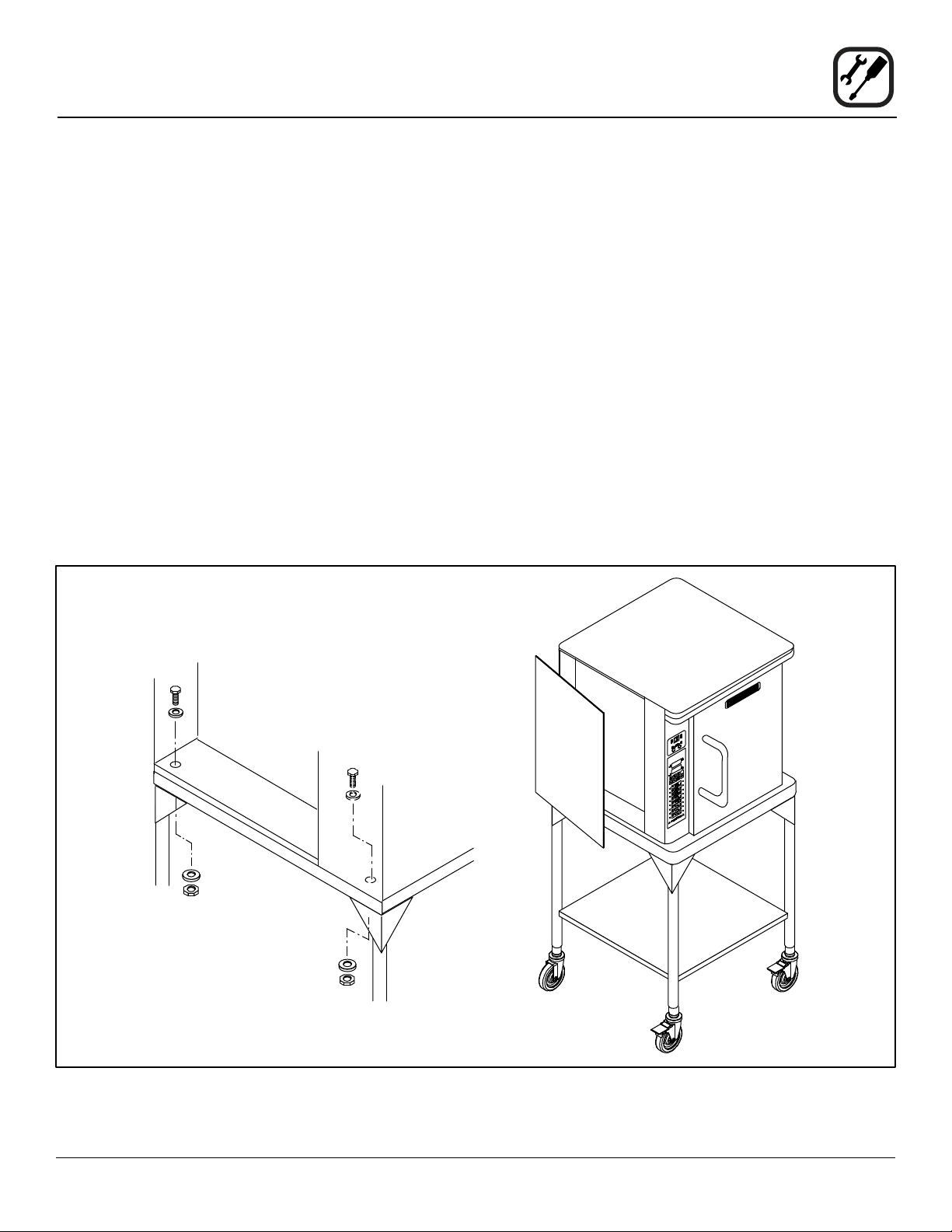
STAND ASSEMBLY
1. Place stand frame upside down on a work surface.
2. Attach one leg to each of the corner stud bolts on the
bottom of the stand top.
3. Place a lock washer and nut on each bolt and tighten.
DO NOT tighten leg bolts completely.
6. Insert a carriage bolt from the outside of the leg,
through the leg, and through the shelf corner bracket.
7. Place a lock washer and nut on each bolt, and tighten
securely.
8. Tighten the leg frame bolts.
4. Place the shelf between the legs so that the smooth
top surface is facing the top of the stand.
5. Align the shelf holes with the bolt holes found near
the bottom of each leg.
Top of
Stand
Attach the legs to
the stand frame
Attach the shelf to the stand
9. Snap the casters into the legs of the stand. Secure by
tightening the locknut.
NOTE: The locking casters must be installed on the
front of the stand.
Shelf
See View A
Bottom View
Attach the casters to the legs
View A
Figure 1
4
Page 7
OVEN ASSEMBLY TO STAND
1. Place the assembled stand in the location where the
oven is going to be used.
Installation
Oven Assembly
7. Place a nut and washer on each of the bolts and tighten securely.
2. Remove the side control compartment cover and
open the front control panel of a single oven (or lower
section).
3. With a tool, punch out the knock-outs in the oven bottom near each corner.
4. Set the on the stand. Center it to the frame.
NOTE: There should be approximately 1/2” of stand
visible on all sides of the unit.
5. Align the front and rear bolt holes of the oven with the
bolt holes in the stand.
6. Insert a bolt and washer, from the top down through
each of the two holes.
8. Replace the oven’s side control compartment, and
close the front control panel.
NOTE: For single section ovens only. For double
stacked ovens step 8 will be completed once
the ovens are stacked.
Oven Leveling
1. Place a level on top of the oven. Loosen the set
screws on the side of each caster. Turn the adjustment collar clockwise to raise and counter clockwise
to lower the oven.
2. When the oven is level, tighten the casters by turning
the two set screws on the side of each caster assembly.
Figure 2
5
Page 8

Installation
Oven Assembly
DOUBLE SECTION ASSEMBLY
There are three stacking congurations available for the
CTBR-AP.
• Two CTBR-AP ovens
• CTB biscuit oven stacked on top of a CTBR-AP
• CTBR-AP stacked on top of a Mark V
See the following pages for stacking instructions for all
congurations.
Two CTBR-AP ovens CTB Biscuit Oven on a CTBR-AP CTBR-AP on a Mark V
Figure 3
6
Page 9

Installation
Oven Assembly
Stacking two CTBR-AP’s or a CTB biscuit oven on top
of a CTBR-AP
NOTE: When stacking a CTBR-AP and CTB biscuit oven
with the FAST timer, the CTB must be placed on
top.
1. Assemble the lower section to the stand.
2. Place the stainless steel crown trim on top of the lower section.
3. Remove the side control compartment cover and
open the front control panel on the upper section.
4. With a tool, punch out the knock-outs in the oven bottom near each corner of the upper section.
5. Punch out the knockouts in the top of the lower section near the left hand corners.
Upper Section
6. Lay the upper section on its back. Attach the self adhesive gasket tape to the front and side edges on the
bottom of the unit.
7. Set the upper section on the lower section.
8. Align the front and rear bolt holes of the upper section
with the bolt holes in the bottom section.
9. Insert a bolt and washer from the top down through
each of the two holes.
10. Place a nut and washer on each of the bolts and tighten securely.
11. Replace the oven side control compartments, and
close the front control panels on both oven sections.
12. Place the top cap on top of the upper unit.
Top Cap
Lower Section
Gasket
Tape
Crown Trim
Double stacked CTBR-AP shown
Figure 4
7
Page 10

Installation
Oven Assembly
Stacking a CTBR-AP on top of a Mark V
1. Lay the Mark V on its back.
2. Remove the 25” legs. Pry the casters out of the old
legs.
3. Attach the 6” legs with casters as follows:
NOTE: The locking casters must be installed on the
front of the oven.
a. Align the threaded stud in each leg with the nut
located inside each bottom corner of the oven
frame. Turn the legs clockwise and tighten to the
nearest full turn.
b. Align the two leg plate holes in each leg with
those in the oven bottom. Secure each leg using
two 1/2” bolts.
c. Pry the foot out of the 6” legs. Snap the casters
into the legs.
d. Tip the oven up on the casters.
4. Remove the crown trim from the Mark V.
5. Bolt the stacking plate to the top of the Mark V with
the studs facing up.
6. Reinstall the crown trim.
7. Lay the CTBR-AP on its back. Attach the self adhesive gasket tape to the front and side edges on the
bottom of the unit.
8. Set the CTBR-AP upright on top of the Mark V.
9. Remove the control compartment cover and access
panel from the CTBR-AP.
10. Align the front and rear bolt holes of the CTBR-AP
with the studs on the stacking plate.
11. Place a nut and washer on each of the studs and
tighten securely.
12. Replace the control compartment cover and access
panel.
13. Insert the ue extension over the ue on the Mark V.
Attach using screws provided.
NOTE: If the oven has a vent guard it must be re-
moved before installing the ue extension.
14. Place the at plate of the ue brace on top the CTBR-
AP. The two holes in the end of the brace must line
up with the holes in the ue extension. Attach the ue
brace to the ue extension with the screws provided.
Attaching the 6’ legs and casters
Figure 5
15. Place the top cap on top of the CTBR-AP.
NOTE: This will secure the ue brace.
Oven Leveling
1. Place a level on top of the oven. Loosen the set
screws on the side of each caster. Turn the adjustment collar clockwise to raise and counter clockwise
to lower the oven.
2. When the oven is level, tighten the casters by turning
the two set screws on the side of each caster assembly.
8
Page 11

Crown Trim
Stud
Installation
Oven Assembly
View A
Stacking
Plate
Top Cap
Stacking Plate
Stud
Attaching the Stacking Plate to the Mark V
Gasket
Tape
See
View A
Attaching the CTBR-AP to the Stacking Plate
Figure 6
9
Page 12

Installation
Oven Assembly
VENTILATION
SINGLE OVENS
1. Mount the vent shield with the vent guard. Align the
mounting holes in the vent shield with top holes in the
vent guard.
DOUBLE STACKED OVENS
Two CTBR-AP’s or a CTB biscuit oven on top of a
CTBR-AP
1. Connect the upper and lower ues with the vent riser.
Mount the vent shield with the vent riser. Align the
mounting holes in the vent shield with top holes in the
vent riser.
Vent
Guard
Vent
Shield
Stacking a CTBR-AP on top of a Mark V
1. Mount the vent shield with the vent guard. Align the
mounting holes in the vent shield with top holes in the
vent guard.
2. Insert the ue extension over the ue on the Mark V.
Attach using screws provided.
NOTE: If the oven has a vent guard it must be re-
moved before installing the ue extension.
3. Slide the at plate of the ue brace under the top cap
on top the CTBR-AP. The two holes in the end of the
brace must line up with the holes in the ue extension.
4. Attach the ue brace to the ue extension with the
screws provided.
Top Cap
Vent
Guard
Vent
Flue
Brace
Shield
Vent
Guard
Vent
Shield
CTBR-AP Single Oven CTBR-AP on a CTBR-AP CTBR-AP on a Mark V
Flue
Extension
Figure 7
10
Page 13

Operation
Safety Information
THE INFORMATION CONTAINED IN THIS SECTION IS
PROVIDED FOR THE USE OF QUALIFIED OPERATING
PERSONNEL. QUALIFIED OPERATING PERSONNEL
ARE THOSE WHO HAVE CAREFULLY READ THE INFORMATION CONTAINED IN THIS MANUAL, ARE FAMILIAR WITH THE FUNCTIONS OF THE OVEN AND/
OR HAVE HAD PREVIOUS EXPERIENCE WITH THE
OPERATION OF THE EQUIPMENT DESCRIBED. ADHERENCE TO THE PROCEDURES RECOMMENDED
HEREIN WILL ASSURE THE ACHIEVEMENT OF OPTIMUM PERFORMANCE AND LONG, TROUBLE-FREE
SERVICE.
Please take the time to read the following safety and operating instructions. They are the key to the successful
operation of your Blodgett convection oven.
11
Page 14

Operation
IQ VVC-208 Control
COMPONENT DESCRIPTION
1. Indicator Lights Light up when product key
is activated.
2. Programming Buttons Used to access programming mode and change
parameters.
3. VFD (Vacuum
Fluorescent Display)
4. Slide-In Menu Strips Menu items are printed
5. Product Buttons Used to activate cook
6. SCAN Key Used for recipe review
7. COOL DOWN key Used to enter or exit cool
8. TEMP/TOGGLE
CLEAR key
9. HOLD key Holds are not used for
10. SETBACK key Used to enter or exit Set-
11. SCK LINK logo Signies your control is
Bright blue for easy viewing. Displays programming
and cook cycle information.
directly on easy-to-change
menu strip.
cycles and for certain programming functions.
during idle.
Used to review time
remaining during multiple
cooks (press & hold)
down mode.
Used to check actual
temperature; also used
to clear value when in
programming mode.
KFC applications. Used to
toggle between upper and
lower case letters when
programming libraries.
back mode.
communications-capable.
Figure 8
12
Page 15

Operation
IQ VVC-208 Control
OVEN OPERATIONAL TEST PROCEDURE
1 Plug oven into electrical source
2 Turn the oven power switch on.
NOTE: AP and Mark V computer is unpowered if off. The XCEL is powered if plugged in.
3 NOTE: This scrolling can be bypassed by pressing SCAN.
The controller will scroll through the following:
a. Appliance Type
b. Software #
c. Download #
d. SCK Address
e. “PREHEAT”
4 The oven will enter “PREHEAT” mode and begin to warm up. When the set temperature (default 325°F) is
reached, the Preheat timer will count down from 45 minutes to zero. When “LOAD” is displayed, the oven is
ready for use.
5 Press any illuminated product key.
6 The cook cycle will count down in the display.
RECIPE REVIEW
Quickly see what is programmed for each product key.
1. Press the SCAN key.
2. Select any product key previously programmed-LED
will be lit above the key.
3. Press the DOWN arrow key to scroll through the list.
4. Press SCAN to exit.
VIEW TEMPERATURE SETTING
1. Press the TEMP key ‘once’ to view Actual Temperature, or
2. Press the TEMP key ‘twice’ to view Set Temperature.
3. Press the TEMP key ‘three’ times to view Fan Speed
4. Press the TEMP key ‘four’ times to view Fan Direction
COOL DOWN
1. To enter Cool Down, press the COOL DOWN key
while the oven door is closed. When the display reads
“COOL,” the door can then be opened.
WARNING!!
THE FAN IS STILL MOVING. DO NOT REACH
INTO THE OVEN. The fan will automatically
shut off when the actual temperature reaches
105°F.
2. To exit Cool Down, press the COOL DOWN key again.
The oven will come back up to set temperature.
WARNING!!
Always turn off main power before removing
bafe or placing hands near fan.
13
Page 16

Operation
IQ VVC-208 Control
SETBACK
1. Used to manually reduce the set temperature tem-
porarily during times of infrequent cooking. Press the
SETBACK key once to reduce the set temperature to
the pre-programmed setback temperature.
2. Press the SETBACK key again to exit Setback and
warm back up to the operating temperature.
PROGRAMMING
Programming Mode for the Vision Controller is entered
by pressing the “P” key for three (3) seconds. The following programming mode is available on the VVC-208 as
follows:
ACCESS LEVEL PASSCODE
Employees 1724
Managers 6647
PROGRAM AREA EMPLOYEE MANAGER
System n/a X
Recipe X na/
Product Name Library X X
Alarm Library X X
SCK Address X X
CHANGING THE MENU STRIP
1 Turn off the oven power.
2 With a Phillips screwdriver, remove the two screws
that secure the bezel of the VVC-208 in place. Remove the bezel.
3 Remove the existing menu strip(s) by lifting the tab
and pulling the menu strip out from the bottom of
the controller.
4 Using the tab as a guide, slide the new menu strip
in.
5 Replace the bezel and screws that secure it to the
controller.
6 Turn on the oven power.
NOTE: Pressing the “P” key saves the previous param-
eter.
NOTE: If no key is pressed within 2 minutes while in Pro-
gramming mode, the controller will automatically
return to idle mode.
NOTE: All scrolling will loop back through allowed values.
14
Page 17

RECIPE PROGRAMMING (1724)
KEY PRESS DISPLAY ACTION
1 Enter Program Mode
Operation
IQ VVC-208 Control
• To enter programming mode,
press and hold the “P” key for 3
seconds.
• Scroll down to “Programming.”
• Press the “P” key to lock in
entry.
2 Enter Pass Code
3 Choose a Product Key (Recipe)
ENTER CODE
****
RECIPE
SELECT PRODUCT TO PROGRAM
Choices are:
ALL, NAME, TIME,
TEMPERATURE, TIMING, SENSI-
TIVITY, FAN SPEED FAN CYCLE,
FAN PULSE ON, FAN PULSE OFF,
ALARM TIME, ALARM NAME,
ALARM DONE, ALARM TONE,
HOLD TIME, HOLD TEMP, HOLD
DONE, HOLD FAN SPEED, PROD-
UCTS HEADS, EXIT
• The display will prompt user to
enter a pass code.
• Enter pass code 1 7 2 4.
• Press the “P” key to lock in your
entry.
• Display will show “Recipe.”
Press the “P” key.
• Press the product key to be
programmed. That key’s LED
will remain lit.
• Scroll to the feature you want
changed and press the “P” key.
NOTE: Selecting “ALL” allows you
to review and/or change all
parameters for that key.
To jump to a specic
feature, select one from
the list and follow the appropriate instructions to
make the changes.
15
Page 18

Operation
IQ VVC-208 Control
RECIPE PROGRAMMING (continued)
KEY PRESS DISPLAY ACTION
4 Choose a Product Name
5 Set Stage 1 Cook Time
6 Set Stage 1 Temperature
7 Set Stage 1 Timing
7A Set Sensitivity
PRODUCT NAME • Press the UP or DOWN arrow
keys to scroll through product
names, OR start spelling the
desired product name by using
the top row of lettered product
keys.
• Press the”P” key to lock in
selection.
STAGE 1 TIME
MM:SS
STAGE 1 TEMP
XXX F
STAGE 1 TIMING (STRAIGHT,
FLEX or
SENSITIVITY)
STAGE 1 SENS
(0 - 9)
• Type in the time for Stage 1.
Range is from 00:00 to 99:59.
• Press the “P” key to advance to
next stage or parameter.
• Type in the Setpoint temperature for this stage. Range is
from 140 to 500F, or the equivalent of Degrees C.
• Press the “P” key to advance to
the next stage or parameter.
• Press the LEFT or RIGHT arrow
keys to select the type of timing
to be used for this stage.
• Press the “P” key to advance to
next stage or parameter.
• THIS ONLY APPEARS IF
SENSITIVITY IS SELECTED
ABOVE
8 Set Stage 1 Fan Speed
9 Set Stage 1 Fan Cycle
STAGE 1 FAN SPEED
(HIGH, LOW)
STAGE 1 FAN CYCLE
(FULL, HEAT, PULSE)
16
• Type in Sensitivity setting of 0-9
• Press the “P” key to advance to
next stage or parameter.
• Press the LEFT or RIGHT arrow
keys to select the fan speed.
• Press the “P” key to advance to
next stage or parameter.
• Press the LEFT or RIGHT arrow
keys to select the fan cycle.
• Press the”P” key to advance to
next stage or parameter.
Page 19

RECIPE PROGRAMMING (continued)
KEY PRESS DISPLAY ACTION
9A Set Stage 1 Fan ON
9B Set Stage 1 Fan OFF
10 If applicable, repeat steps 5-9 for additional stages.
A total of 9 stages can be programmed.
11 Set Alarm 1 Time (Selectable)
12 Set Alarm 1 Name (Selectable)
STAGE 1 FAN CYCLE
(FULL, HEAT, PULSE)
STAGE 1 FAN OFF NOTE: THIS SECTION ONLY AP-
ALARM 1 TIME
MM:SS
ALARM 1 NAM
“ACTION”
Operation
IQ VVC-208 Control
• Press the LEFT or RIGHT arrow
keys to select the fan cycle.
• Press the “P” key to advance to
next stage or parameter.
PEARS IF “PULSE” IS SELECTED FOR FAN CYCLE.
• Type in desired fan OFF time.
• Press the “P” key to advance to
next stage or parameter.
• Type in Alarm Time for activating the Action Alarm. Skip Steps
11-14 if the Alarm Time for this
stage is zero.
• Press the “P” key to advance to
the next stage or parameter.
• Press the UP or DOWN arrow
keys to scroll through the Alarm
Names, OR start spelling the
desired action alarm name by
pressing the appropriate product keys.
• Press “P” key to lock in the
13 Set Alarm #1
Done Mode (selectable)
14 Setting Alarm 1 Tone
DOUBLE, LONG/SHORT, NONE
15 If applicable, repeat Steps 10-13 for additional Action Alarms.
A total of three (3) Action Alarms can be programmed.
ALARM 1 DONE
(AUTOMATIC, MANUAL)
ALARM 1 TONE
SHORT, MEDIUM, LONG,
17
selection.
• Press the LEFT or RIGHT arrow
keys to select how the Action
Alarm is to be canceled.
• Press the “P” key to advance to
next stage or parameter.
• Press the LEFT or RIGHT arrow
keys to select Alarm Tone.
• Press the “P” key to advance to
next stage or parameter.
Page 20

Operation
IQ VVC-208 Control
RECIPE PROGRAMMING (continued)
KEY PRESS DISPLAY ACTION
16 Select Hold Time
HOLD TIME
00:00
• Type in the length of hold time
required. The value is in the
range of 00:00 to 99:59.
17 Set Hold Temp
18 Set Hold Done
19 Set Hold Fan Speed
20 Set Product Heads
21 Select Another Product Key
HOLD TEMP
XXXF
HOLD DONE
(AUTOMATIC, MANUAL)
HOLD FAN SPEED
(HIGH, LOW)
PRODUCT HEADS
XX
SELECT PRODUCT
TO PROGRAM
• Press the “P” key to advance to
the next step or parameter.
• Type in desired Hold temperature.
• Press the “P” key to advance to
the next step or parameter.
• Press the LEFT or RIGHT arrow keys to select how the hold
alarm is to be cancelled.
• Press the “P” key to advance to
the next step or parameter.
• Press the LEFT or RIGHT arrow keys to select the hold fan
speed.
• Press the “P” key to advance to
the next step or parameter.
• Type in the proper count value.
The range is 0-99 pieces.
• Press the “P” key to advance.
• Repeat from step #3 in this
section, or press the”P” key and
scroll to Exit.
18
• Press the “P” key to exit programming.
Page 21

SYSTEM PROGRAMMING (6647)
KEY PRESS DISPLAY ACTION
1 Enter Program mode
Operation
IQ VVC-208 Control
• To enter programming mode,
press and hold the “P” key for 3
seconds.
• Scroll Down to Programming.
• Press the “P” key to lock in your
entry.
2 Enter pass code
3 Conrm or Select Appliance Type
4 Select Language
5 Set Tone Level
ENTER CODE
****
APPLIANCE TYPE
(ELECTRIC HALF,
ELECTRIC FULL)
HALF = AP
FULL = MARK V
SELECT LANGUAGE
(English, Other)
TONE LEVEL
(None, 1, 2, 3, 4)
• The display will prompt user to
enter a pass code.
• Enter pass code 6 6 4 7.
• Press the “P” key when “System” is displayed.
• Press the “P” key again to enter
System Programming.
• Press the LEFT or RIGHT arrow
keys to select from a pre-programmed list of appliances.
NOTE: Changing appliance
type clears all current
recipe programs.
• Press the “P” key to lock in your
entry
• Press the LEFT or RIGHT arrow
key to select language
• Press the “P” key to lock in your
entry
NOTE: ‘Other’ is downloadable.
• Press the LEFT or RIGHT arrow keys to select a tone level.
At each level the controller will
continuously sound the selected
tone.
• Press the “P” key to lock in your
entry
19
Page 22

Operation
IQ VVC-208 Control
SYSTEM PROGRAMMING (continued)
KEY PRESS DISPLAY ACTION
6 Set Temperature Mode
7 Program Setback Time
8 Program Setback Temperature
9 Set Hold Time
TEMPERATURE
F = FAHRENHEIT or
C = CELSIUS
SETBACK TIME
HH:MM
SETBACK TEMP
XXX
HOLD TIME
HH:MM
• Press the LEFT or RIGHT arrow
keys to select the method that
all temperatures will be displayed in.
• Press the ”P” key to lock in your
entry
• Press the numbered product keys to select the time in
HH:MM format for activating
Setback mode.
NOTE: 0:00 is default to disable
Setback.
• Press the “P” key to lock in your
entry
• Press the numbered product
keys to select the Setback
temperature in the range of
140-300°F.
• Press the “P” key to lock in your
entry
• Type in the length of hold time
required. The value is in the
range of 00:00 to 99:59.
10 Set Hold Temperature
11 Set Hold Done
12 Set Hold Fan Speed
HOLD TEMP
XXX
HOLD DONE
(AUTOMATIC, MANUAL)
HOLD FAN SPEED
(HIGH, LOW)
20
• Press the “P” key to advance to
the next stage or parameter.
• Type in the desired Hold temperature. Hold Temperature
Range is 140-210°F
• Press the “P” key to advance to
the next stage or parameter.
• Press the LEFT or RIGHT arrow
keys to select Hold Done.
• Press the “P” key to advance to
the next stage or parameter.
• Press the LEFT or RIGHT arrow
keys to select Hold Fan Speed.
• Press the “P” key to advance to
the next stage or parameter.
Page 23

SYSTEM PROGRAMMING (continued)
KEY PRESS DISPLAY ACTION
13 Set Preheat Time
14 Exit Program Mode
Operation
IQ VVC-208 Control
PREHEAT TIME
MM:SS
EXIT • Press the UP or DOWN arrow
• Type in the desired Preheat
Time.
• Press the “P” key to advance to
the next stage or parameter.
keys to scroll to “Exit.”
15
PRODUCT OR ALARM NAME LIBRARIES (6647)
KEY PRESS DISPLAY ACTION
1 Enter Program mode
2 Enter Pass Code
SYSTEM PROGRAMMING
****
• Press the “P” key to return to
idle mode.
• To enter programming mode,
press and hold the “P” key for 3
seconds.
• Scroll Down to Programming.
• Press the “P” key to lock in your
entry.
• Enter pass code 6 6 4 7.
• Press the “P” key to lock in your
entry.
3
PROD NAME LIB
Or
ALARM LIB
21
• Scroll to “Prod Name Lib” or
“Alarm Lib”
• Press the “P” key to advance.
Page 24

Operation
IQ VVC-208 Control
PRODUCT OR ALARM NAME LIBRARIES (continued)
KEY PRESS DISPLAY ACTION
4 From this point, you can either MODIFY an Existing Name, or ADD a New Name.
4A MODIFY or ADD an Existing
Product or Alarm Name
4B
Prod Name Lib
xxxxxxxx
OR
Alarm Name Lib
xxxx
• Start spelling the name (predic-
tive method) using keys 1-10,
OR
• Use the UP and DOWN arrow
keys to scroll through the library
(traditional method).
• Once name is located, press
the SCAN key to toggle from
predictive text input to traditional
text input.
4C
4D
• Use the LEFT and RIGHT arrow
keys to move the cursor.
SAVE LIBRARY
MODIFY, ADD, CANCEL
• Press “HOLD” to toggle between Upper and Lower case.
• “TEMP/TOGGLE CLEAR” can
be used to clear the existing
product name.
• Press the “P” key to complete.
• Press the LEFT or RIGHT arrow
keys to select “Modify” or “Add.”
• Press the “P” key.
NOTE: Selecting “Cancel” al-
lows you to exit without
making any changes.
4E Exit Program Mode
EXIT • Press the UP or DOWN arrow
keys to scroll to “Exit.”
22
Page 25

SCK ADDRESS (6647)
KEY PRESS DISPLAY ACTION
1 Enter Program Mode
2 Enter Pass Code
ENTER CODE
****
Operation
IQ VVC-208 Control
• To enter programming mode,
press and hold the “P” key for 3
seconds.
• Scroll to Programming.
• Press the “P” key.
• The display will prompt user to
enter a pass code.
• Enter pass code 6 6 4 7.
• Press the “P” key to lock in your
entry.
• Scroll to SCK Address.
• Press “P” to advance.
3 Set SCK Address
4 Set SCK Node
5 Exit SCK Programming
SCK ADDRESS
XX
NETWORK NODES
XX XX XX XX XX
EXIT • Scroll to Exit.
• Press the LEFT or RIGHT arrow keys to scroll through the
SCK address to be used for this
controller. The range is from 1
to 31, or “Auto Assign.”
• Press the “P” key to lock in your
selection.
• The display will scroll in mar-
quee-style all SCK Nodes cur-
rently in the system. Scrolling
will constantly be updated.
• Press the “P” key to advance.
• Press the “P” key to return to
idle.
23
Page 26

Maintenance
Cleaning and Preventative Maintenance
CLEANING THE OVEN
Refer to KFC Equipment Standards Library Volume 2 -
CTBR-AP for morning start-up and nightly cleaning procedures.
There are two critical performance areas that warrant
daily cleaning. These include:
• Fan Wheel
• Probe
Cleaning the Fan Wheel
1. Hold the fan wheel with a gloved hand.
2. Use the L-shaped oven brush to clean the ns on the
fan wheel.
3. Use the hand brush to clean the center portion of the
blower wheel.
4. Wipe all around the fan with a damp towel.
L Shaped Brush
PREVENTATIVE MAINTENANCE
The best preventative maintenance measures are the
proper installation of the equipment and a program for
routinely cleaning the ovens.
Annual Maintenance
This oven requires no lubrication, however, the venting
system should be checked annually for possible deterio-
ration resulting from moisture and corrosive ue products.
If maintenance or repairs are required, contact your local
Blodgett service company, a factory representative or the
Blodgett Oven company.
WARNING!!
Always disconnect the appliance from the
power supply before servicing or cleaning.
Hand Brush
Figure 9
Cleaning the Probe
1. Use the L shaped brush to clean behind the probe.
2. Use a damp towel to wipe the probe.
Cleaning Behind the Bafe Panel
1. Use the hand brush to clean around the heating ele-
ment area behind the bafe panel.
24
 Loading...