

Page 1
TM
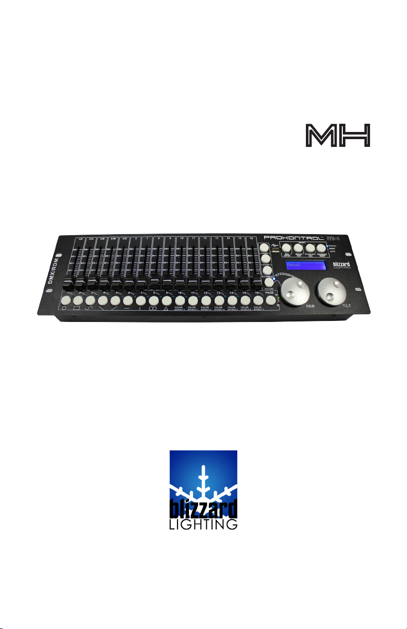
PROKONTROL
MH
Blizzard Lighting, LLC
www.blizzardlighting.com
Waukesha, WI USA
Copyright (c) 2015
Page 2

TABLE OF CONTENTS
1. GETTING STARTED 3
1.1 What’s In The Box? 3
1.2 Getting It Out Of The Box 3
1.3 Powering Up! 3
1.4 Getting A Hold Of Us 3
1.5 Instructions on Our Instructions 4
2. INTRODUCTION 5
2.1 Features 5
2.2 General Overview 5
2.3 The ProKontol™ MX Pin-up Pictures 5
2.4 Button and Fader Functions 5
2.5 Common Terms 7
3. OPERATING INSTRUCTIONS 8
3.1 Setup 8
3.1.1 Setting Up The System 8
3.2 LCD Menu Navigation 8
3.4 Fixture Adressing / Patching Fixtures and Faders 9
3.4 Fixture Patching Instructions (Step by Step) 10
3.5 System Functions 11
3.5.1 Resetting the Systems 11
3.5.2 Delete All Fixture Patches 11
3.5.3 Data Back-Up 11
3.5.4 Load Data 11
3.5.5 Send Fixture Update File 11
3.5.6 RDM DMX Address Setup 12
3.6 Manual Fixture Control 12
3.7 Fade Mode 12
3.8 Built-In Movement and Color Effects 12
3.9 Scenes and Chases 13
3.9.1 Scene Editing 13
3.9.2 Chase Editing 13
3.9.3 Run Scenes 13
3.9.4 Run Chases 13
3.9.5 Fade In/Out Time of Color Channels 14
3.9.6 Firmware Updates 14
4. APPENDIX 15
4.1 A Quick Lesson On DMX 15
4.2 Keeping Your ProKontrol™ MH As Good As New 16
4.3 Returns (Gasp!) 16
4.4 Shipping Issues 16
4.5 Tech SPECS! 17
ProKontrol MH Manual Rev. B © 2013-15 Blizzard Lighting, LLC
Page 2
Page 3

1. GETTING STARTED
What’s In The Box?
• 1x PROKONTROL™ MH DMX Controller
• 1x 9 VDC, 800ma AC/DC Adaptor
• A Warranty Card & Warranty Info
• This Lovely User Manual
1.2 Getting It Out Of The Box
We could tell just by lookin’ atcha. You’re a bit of a control freak, aren’t ya? Just kidding!
CONGRATULATIONS! You’ve purchased a GREAT little DMX controller! Bravo! Now that
you’ve got your PROKONTROL™ MH, you should carefully unpack the box and check the
contents to ensure that all parts are present and in good condition. If anything looks as if it
has been damaged in transit, notify the shipper immediately and keep the packing material
for inspection. Again, please save the carton and all packing materials. If a xture must be
returned to the factory, it is important that the xture be returned in the original factory
box and packing.
1.3 Powering Up!
All xtures must be powered directly off a switched circuit and cannot be run off a
rheostat (variable resistor) or dimmer circuit, even if the rheostat or dimmer
channel is used solely for a 0% to 100% switch.
AC Voltage Switch - Not all xtures have a voltage select switch, so please verify that the
xture you receive is suitable for your local power supply. See the label on the xture or
refer to the xture’s specications chart for more information. A xture’s listed current
rating is its average current draw under normal conditions. Check the xture or device
carefully to make sure that if a voltage selection switch exists that it is set to the correct
line voltage you will use.
Warning! Verify that the voltage select switch on your unit matches the line
voltage applied. Damage to your xture may result if the line voltage applied does
not match the voltage indicated on the voltage selector switch. All xtures must
be connected to circuits with a suitable Ground (Earthing).
1.4 Getting A Hold Of Us
If something is wrong, please just visit our website at www.blizzardlighting.com
and open a support ticket. We’ll be happy to help, honest.
Blizzard Lighting
N16 W23390 Stoneridge Dr. Suite E
Waukesha, WI 53188 USA
www.blizzardlighting.com
414-395-8365
Disclaimer: The information and specications contained in this document are subject
to change without notice. Blizzard Lighting™ assumes no responsibility or liability for any
errors or omissions that may appear in this user manual. Blizzard Lighting™ reserves the
right to update the existing document or to create a new document to correct any errors
or omissions at any time. You can download the latest version of this document from www.
blizzardlighting.com.
Author: Date: Last Edited: Date:
J. Thomas 8/5/2013 J. Thomas 9/18/2015
ProKontrol MH Manual Rev. B © 2013-15 Blizzard Lighting, LLC
Page 3
Page 4
IMPORTANT SAFETY INSTRUCTIONS
• Please keep this User Guide for future use. If you sell the unit to
someone else, be sure that they also receive this User Guide.
• ALWAYS make sure that you are connecting to the proper voltage,
and that the line voltage you are connecting to is not higher than
that stated on the decal or rear panel of the xture.
• This product is intended for indoor use only.
• To prevent risk of re or shock, do not expose xture to rain or mois-
ture.
• Make sure there are no ammable materials close to the unit while
operating.
• ALWAYS disconnect from the power source before servicing or replacing fuse and be sure to replace with same fuse size and type.
• DO NOT operate at ambient temperatures higher than 104°F (40°C).
• In the event of a serious operating problem, stop using the unit immediately. NEVER try to repair the unit by yourself. Repairs carried
out by unskilled people can lead to damage or malfunction. Please
contact the nearest authorized technical assistance center. Always
use the same type spare parts.
• Make sure the power cord is never crimped or damaged.
• Never disconnect the power cord by pulling or tugging on the cord.
• Avoid direct eye exposure to the light source while it is on.
Caution! There are no user serviceable parts inside the unit. Do not open the
housing or attempt any repairs yourself. In the unlikely event your unit may require service, please contact Blizzard Lighting at support@blizzardlighting.com.
1.5 Instructions on Our Instructions
We try to make these manuals easy to read and as fun as reading an instruction manual can be. Because there are buttons, switches, sliders and knobs
galore on most of our products, it makes sense to refer to things in a consistent
fashion. So, when you see text formatted in certain ways, it should say to you
“Hey! Look at me! I MEAN something, dammit!”
Special Text What It Means
LCD
<MENU> Button <X> to be pressed
ProKontrol MH Manual Rev. B © 2013-15 Blizzard Lighting, LLC
Text displayed on the xture’s LCD control panel
Page 4
Page 5
2. INTRODUCTION
proKO NTROL MH
™
2.1 Features
• DMX512 standard with RDM protocol compatibilty.
• 512 DMX channels
• Controls up to 32 xtures, each with up to of 18 DMX channels
• Fixture starting addresses and channels can be soft patched
• 32 chases, able to run 5 chases simultaneously
• 32 scenes, all scenes are able to be operated simultaneously
• 9 built-in effect buttons for moving head xtures, plus 7 built-in
color effect buttons
• USB port for rmware updates and data backup
• Sound control via built-in microphone
2.2 General Overview
The ProKontrol™ MH is a universal intelligent lighting controller with RDM
protocol compatibilty. Once properly patched it it’s the perfect controller for
any moving head xture, allowing ease of use with its dedicated PAN and TILT
wheels. It allows the control of 32 xtures composed of 18 channels each.
Programs can be triggered by music, automatically, or manually. You can run up
to 5 chases, and all scenes can be executed at the same time.
On the surface you will also nd a variety of programming tools such as 16
universal c-hannel sliders, quick access “Movement” and built-in “Color Effect”
buttons, plus an LCD display indicator for easy navigation of all controls and
menu functions.
2.3 The ProKontrol™ Pin-up Pictures
ProKontrol MH Manual Rev. B © 2013-15 Blizzard Lighting, LLC
Page 5
Page 6
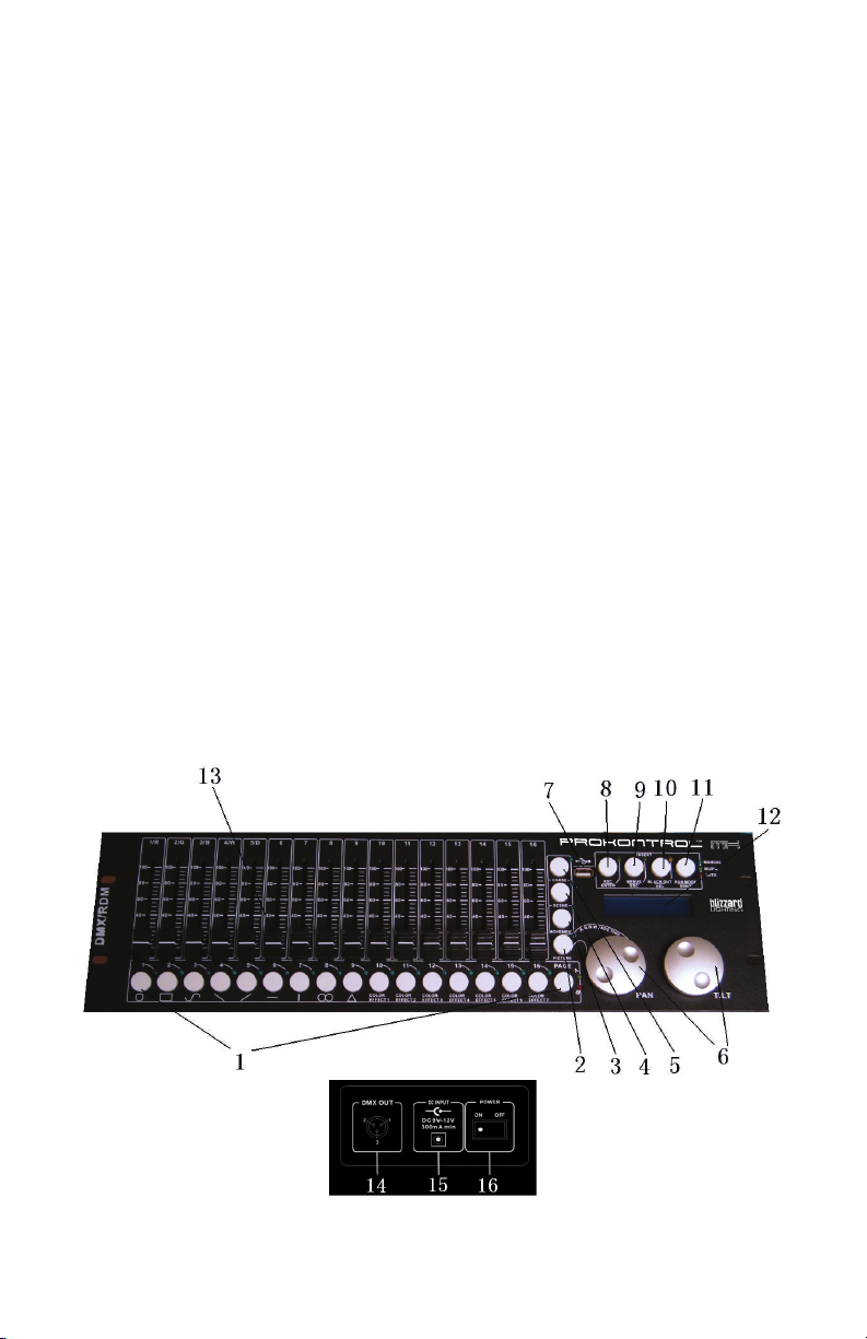
2.4 Button and Fader Functions
Number Button/Fader/Connection Does...
1 NUMBER Buttons
2 FIXTURE Button
3 MOVEMENT Button
4 SCENE Button
5 CHASE Button
6 PAN/TILT Wheels
7 USB Port
8 REC/ENTER Button REC/ENTER
9 MENUS/ESC Button MENUS/ESC
10 BLACKOUT/DEL Button BLACKOUT/DELETE
11 RUN MODE/SWAP Button RUN MODE/SWAP
12 LCD Screen LCD Screen
13 Faders Adjusts the DMX output value
14 DMX Out DMX Out (3-pin)
15 DC Input DC Input
16 Power On/Off Power On/Off
Functions differently in different
modes.
When activated, the 16 number but-
tons xture selection.
When activated, the 16 number buttons built-in movements/macros.
When activated, the 16 number buttons scene playback
When activated, the 16 number buttons are for chase playback.
Functions differently in different
modes.
Used for rmware updates and data
backup. FAT32 and FAT16 supported.
Number Buttons
• In CHASE mode, press a number button, the chase will be activated or
deactivated.
• In SCENE mode, press a number button, the scene will be activated or
deactivated.
• In MOVEMENT mode, press a number button, the movement will be
activated or deactivated.
• In FIXTURE mode, press a number button, a xture will be selected or
deselected.
Faders
• In FIXTURE mode, move a fader to adjust the DMX output value.
Pan/Tilt Wheels
• In CHASE mode, PAN/TILT wheels are to adjust the chase speed and time
respectively.
• In SCENE mode, nothing dened in PAN/TILT wheels.
• In MOVEMENT mode, PAN/TILT wheels are to adjust the MOVEMENT
parameters.
• In FIXTURE mode, PAN/TILT wheels are to adjust the output values of PAN/
TILT.
ProKontrol MH Manual Rev. B © 2013-15 Blizzard Lighting, LLC
Page 6
Page 7

2.5 Common Terms
The following are common terms used in intelligent light programming, so pay
attention! We’ll be using many of them throughout the manual.
• Blackout is a state by where all lighting xtures light output are set
to 0 or off, usually on a temporary basis.
• DMX-512 stands for Digital MultipleX is an industry standard digital
communication protocol used in entertainment lighting equipment.
For more information read the DMX Primer and DMX Control Mode
Sections later in the manual.
• Fixture refers to your lighting instrument or other device such as a
fogger or dimmer of which you can control.
• Programs are a bunch of scenes stacked one after another. It can be
programmed as either a single scene or multiple scenes in sequence.
• Scenes are static lighting states.
• Sliders are a delicious small burger or sandwich, but here they are
used in the same context as faders.
• Chases can also be called programs. A chase consists of a number of
scenes stacked one after another.
• Scanner refers to a lighting instrument with a pan and tilt mirror;
however, in the ProKontrol™ MH controller it can be used to control
any DMX-512 compatible device as a generic xture.
• Stand Alone refers to a xture’s ability to function independently of
an external controller and usually in sync to music, due to a built in
microphone.
• Fade Slider is used to adjust the time between scenes within a
chase.
• Speed Slider affects the amount of time a scene will hold its state. It
is also considered a wait time.
• Shutter is a mechanical device in the lighting xture that allows you
to block the lights path. It is often used to lessen the intensity of the
light output and to strobe.
• Patching refers to the process of assigning xtures a DMX channel.
• Playbacks can be either scenes or chases that are directly called to
execution by the user. A playback can also be considered program
memory that can be recalled during a show.
ProKontrol MH Manual Rev. B © 2013-15 Blizzard Lighting, LLC
Page 7
Page 8

3. OPERATING INSTRUCTIONS
3.1 Setup
3.1.1 Setting Up The System
Plug the AC to DC power supply to the system back panel and to the mains
outlet.
Plug in your DMX cable(s) to your intelligent lighting as described in the xtures
respective manual. For a quick lesson on DMX see the DMX Primer section in
the Appendix of this manual.
3.2 LCD Menu Navigation
Press and hold the <MENUS> button for 2 seconds to enter/exit Menu Mode.
The menu options are as follows:
01. Patch Fixture - To patch xtures starting addresses and the
channel position, etc.
02. Reset Factory - To restore the factory settings.
03. Delete All Fixture Patch - To delete all patch settings.
04. Fade Mode - To set fade time mode.
05. RDM DMX Address Setup - To implement RDM functions.
06. Data Back Up - To back up data to a USB memory stick.
07. Data Load - To load data from a USB memory stick.
08. Send Fixture Update File - To send the xture update code.
The PAN wheel is used to browse between the menu options.
ProKontrol MH Manual Rev. B © 2013-15 Blizzard Lighting, LLC
Page 8
Page 9

3.3 Fixture Adressing / Patching Fixtures and Faders
This controller is programmed to control 18 channels of DMX per xture on its 16
faders plus the PAN and TILT encoder wheels.
To take full advantage of your ProKontrol™ MH, you’ll need to patch in the DMX
address codes of the xtures and faders. The address of the xtures and faders can
be changed as needed, but rst let’s just look at the default values.
The default Fixture Patch Settings are:
Page Fixture DMX Start Address Page Fixture DMX Start Address
1 001
2 019 18 307
3 037 19 325
4 055 20 343
5 073 21 361
6 091 22 379
7 109 23 397
8 127 24 415
A
9 145 25 433
10 163 26 451
11 181 27 469
12 199 28 487
13 217 29 505
14 235 30 (Blank)
15 253 31 (Blank)
16 271 32 (Blank)
17 289
B
And the default Fader Patch Setting are:
Fader DMX Ch. Fader DMX Ch. Fader DMX Ch.
1/R (Red) 1 7 7 13 13
2/G (Green) 2 8 8 14 14
3/B (Blue) 3 9 9 15 15
4/W (White) 4 10 10 16 16
5/D (Dimmer) 5 11 11 PAN 17
6 6 12 12 TILT 18
In the above table, R=RED, G=GREEN, B=BLUE, W=WHITE, D=DIMMER
DMX START ADDRESS + FADER CHANNEL, - 1 = FADER DMX ADDRESS
For example: With these default xture patch settings, the FIXTURE 1 PAN DMX
address is 17, so xiture 2 PAN DMX address would be 35.
Before controlling a xture without RDM function, you need to patch the xture’s
DMX starting address. For example, if you are patching a moving head, you
must patch the pan/tilt channels of the moving head to PAN/TILT wheels on the
ProKontrol MH. If you are patching an LED xture, then, you must patch the Red,
Green, Blue, White and Dimmer channels to the corresponding faders respectively.
The ProKontrol MH will then be able to correctly run all of its built-in movements
and fade in/out effects with the patch setting.
ProKontrol MH Manual Rev. B © 2013-15 Blizzard Lighting, LLC
Page 9
Page 10

3.4. Fixture Patching Instructions (Step by step)
Follow these steps to begin patching your xtures:
1. Press and hold <MENUS> for 2 seconds to enter Menu Mode.
2. Rotate the PAN wheel to locate: 01. PATCH FIXTURE.
3. Press <ENTER> to conrm.
4. Select a xture (only one xture can be selected).
5. Press <SWAP> to switch between the four settings: DMX START
ADDRESS, FADER CHANL, FADER REVERSE and COLOR FADE.
6. In DMX START ADDRESS, rotate the PAN wheel to adjust the DMX
start address; press <ENTER> to save, or press <DEL> to delete
the existing DMX start address.
7. In FADER CHANL, rotate the PAN wheel to select a fader name
within “1/R” to “TILT”. Rotate the TILT wheel to adjust the address
of the corresponding DMX channel within 1-40. Press <ENTER> to
save the patching or press <DEL> to delete the existing patching.
8. In FADER REVERSE, rotate the PAN wheel to select a fader name
within “1/R” to “TILT”. Rotate the TILT wheel to select YES or NO;
YES means to set the corresponding channel reverse; NO means
inverse. Press <ENTER> to save the setting.
9. In COLOR FADE, you can enable or disable the fade in/out time of
the xture’s color channels. Rotate the PAN wheel, select YES or
NO; YES means to enable; NO means to disable. Press <ENTER>
to save the settings.
10. To copy a patched xture to a new xture, press and hold the
number button of the patched xture, then press the number
button of a new xture.
11. Press <ESC> to exit patch setting.
*DMX START ADDRESS + FADER CHANNEL, - 1 = FADER DMX ADDRESS
Example: If FIXTURE 1 is set to 11 as its DMX starting address, and its 1/R
fader channel is set to 1, when you move the 1st fader the output of the 11th
DMX channel will be changed.
But, if FIXTURE 1 is set to 11 as its DMX starting address, and its 1/R fader
channel is set to 10, and you move the 1st fader, the output of the 20th DMX
channel will be changed.
When patching, a “!” mark will be shown in the LCD display when there is
a overlap in the patching of DMX channels. This will need to be corrected,
otherwise the DMX output may run in error.
ProKontrol MH Manual Rev. B © 2013-15 Blizzard Lighting, LLC
Page 10
Page 11

3.5 System Functions
3.5.1 Resetting The System
WARNING: This will reset the controller to its factory defaults. ALL PROGRAMS AND
SETTINGS WILL BE ERASED!
1. Press and hold <MENUS> for 2 seconds to enter Menu Mode.
2. Rotate the PAN wheel to locate “02. Reset factory”.
3. Press <ENTER> to conrm.
4. Rotate the PAN wheel to select YES or NO.
5. Press <ENTER> to conrm or <ESC> to return to the main menu.
3.5.2 Delete All Fixture Patches
1. Press and hold <MENUS> for 2 seconds to enter Menu Mode.
2. Rotate the PAN wheel to locate “03. delete all Fixture patch”.
3. Press <ENTER> to conrm.
4. Rotate the PAN wheel to select YES or NO.
5. Press <ENTER> to conrm or <ESC> to return to the main menu.
3.5.3 Data Back-Up to USB Memory Stick
1. Press and hold <MENUS> for 2 seconds to enter Menu Mode.
2. Rotate the PAN wheel to locate “06. Data back up”.
3. Press <ENTER> to conrm.
4. Insert a USB memory stick to the USB port.
5. Rotate the PAN wheel to select YES or NO; press <ENTER> to conrm.
6. Press a number button to store the back-up le. Up to 16 les can be
backed up, respectively stored in number 1-16 buttons. If the LED indicator
of a number button is on, it means there is back-up le in this position.
7. Press the <ESC> button to return to the main menu.
3.5.4 Load Data From USB Memory Stick
1. Press and hold <MENUS> for 2 seconds to enter Menu Mode.
2. Rotate the PAN wheel to locate “07. data load.”
3. Press <ENTER> to conrm.
4. Make sure your USB memory stick is in the USB port.
5. Rotate the PAN wheel to select YES or NO; press <ENTER> to conrm.
6. Press a number button to load the back-up le. Up to 16 les can be
backed up, respectively stored in number 1-16 buttons. If the LED indicator
of a number button is on, it means there is back-up le in this position.
7. Press the <ESC> button to return to the main menu.
3.5.5 Send Fixture Update File (RDM Fixtures Only)
Through the DMX cable, send xture rmware code.
1. Press and hold <MENUS> for 2 seconds to enter Menu Mode.
2. Insert a USB memory stick to the USB port.
3. Rotate the PAN wheel to locate “08. Send xture Update le”.
4. Press <ENTER> to conrm.
5. Rotate the PAN wheel to locate the le to send.
6. Press <ENTER> to start sending.
7. Repeat Step 4 and 5 to send another le.
8. Press the <ESC> button to exit.
ProKontrol MH Manual Rev. B © 2013-15 Blizzard Lighting, LLC
Page 11
Page 12

3.5.6 RDM DMX Address Setup
1. Press and hold <MENUS> for 2 seconds to enter Menu Mode.
2. Rotate the PAN wheel to locate “05. RDM DMX Address setup”.
3. Press <ENTER> to conrm.
4. Rotate the PAN wheel to select YES or NO; If YES and you press
<ENTER> you will enter RDM operation.
5. The ProKontrol™ MH will search and show the number of RDM
devices.
6. Rotate the PAN wheel to select an RDM device; rotate the TILT wheel
to adjust the DMX address of the RDM device. Press <ENTER> to
conrm.
7. Press <SWAP> to switch the information of the selected device,
Press <DEL> to verify the selected device.
8. Press <ESC> to return to the main men
3.6 Manual Fixture Control
1. Press the <FIXTURE> button to activate FIXTURE mode.
2. Select the desired xtures with the number buttons (1-16) and the
PAGE button (PAGE A: 1-16, PAGE B: 17-32).
3. Move the faders and/or wheels to adjust the DMX output values. In
Step 2, xtures can be selected one by one; Alternatively, you can
select more xtures in a single operation. For example, to select
Fixture 1-8, you can press and hold the number button 1 and then
press the number button 8, Fixture 1-8 will all be selected. The same
can be applied to deselect xtures.
3.7 Fade Mode
1. Press and hold <MENUS> for 2 seconds to enter Menu Mode.
2. Rotate the PAN wheel to locate “04. Fade mode”.
3. Press <ENTER> to conrm.
4. Rotate the PAN wheel to select ALL CHANNEL or ONLY PAN/TILT.
5. Press <ENTER> to conrm or <ESC> to return to the main menu.
3.8 Built-In Movement and Color Effects
There are 9 built-in “movements” in the ProKontrol™ MH, and 7 built-in color
macros for LED xtures. Before running a movement, all xtures must be
patched correctly.
1. Press the <FIXTURE> button to enter FIXTURE mode (indicator on).
2. Select the desired xtures with the number buttons (1-16) and the
PAGE button (PAGE A: 1-16, PAGE B: 17-32).
3. Press the <MOVEMENT> button to activate the MOVEMENT mode.
4. Select a desired MOVEMENT/MACRO with the number buttons (1-16).
5. Movement 1-9 is for the pan/tilt movement of moving heads. By
using the <SWAP> button, toggle through the options.
ProKontrol MH Manual Rev. B © 2013-15 Blizzard Lighting, LLC
Page 12
Page 13

Movement Range
Pan: 0-100% TL: 0-100%
Adjusts the movement size.
Movement Offset
Pan: 0-255 TL: 0-255
Adjusts the movement center point.
Movement Speed
0.00-30.00s
Adjusts the time needed to complete one step.
Delay Level
Level: 00-25
Steps to offset each xture.
6. Press <SWAP> to switch between the adjustable parameters.
3.9 Scenes and Chases
3.9.1 Scene Editing
Channels and movements can be edited in a static scene.
1. Press and hold the <REC> button for 2 seconds to enter Editing
Mode.
2. Press the <FIXTURE> button (indicator on).
3. Select the desired xture(s) with the number buttons (1-16) and the
PAGE button (PAGE A: 1-16, PAGE B: 17-32).
4. Move the faders and/or wheels to adjust the DMX output values.
Movements can also be included.
5. Press the <REC> button to get ready to save.
6. Press the <SCENE> button and then press a number button to save
the scene. There are two pages (Page A and B) to save the scenes.
Once a scene is saved successfully, all the LED indicators will blink 3
times.
7. Repeat Step 3-6 to edit another scene.
8. Press and hold the <REC> button for 2 seconds to exit Editing Mode.
3.9.2 Chase Editing
Channels, scenes and movements can be edited in a chase.
1. Press and hold the <REC> button for 2 seconds to enter Editing
Mode.
2. Press the <CHASE> button (indicator on).
3. Select a number button for the chase.
ProKontrol MH Manual Rev. B © 2013-15 Blizzard Lighting, LLC
Page 13
Page 14

4. Press the <FIXTURE> button (indicator on).
5. Select the desired xture(s) with the number buttons (1-16) and the
PAGE button (PAGE A: 1-16, PAGE B: 17-32).
6. Move the faders and/or wheels to adjust the DMX output values.
Scenes and/or movements can also be included.
7. Press the <REC> button to save the current step.
8. Repeat Step 4-5 to edit a new step while in <CHASE> mode, you
can rotate the PAN wheel to browse all the steps. You can also press
the <INSERT> button to insert a step. Repeat Step 3-6 to edit another
scene.
9. When all the steps are edited, press the <CHASE> button then
press the number button to save (the same button as step 3).
10. Press and hold the <REC> button for 2 seconds to exit Editing
Mode.
3.9.3 Run Scenes
1. Press the <SCENE> button (indicator on).
2. Press the number button(s) to activate the scene(s).
3. Note: Scenes may be stacked. The last scene takes precedence.
3.9.4 Run Chases
1. Press the <CHASE> button (indicator on).
2. Press the number button(s) to activate the chase(s). Maximum 5
chases can be output simultaneously.
3. Press <RUN MODE> to select a run mode:
• AUTO: Chases run in the sequences of the numbers.
• MANUAL: Rotate the PAN wheel to run step by step, forward or
backward.
MUSIC: The chases will be activated by sound. To adjust the sensitivity of
sound activation in MUSIC mode, press and hold and then rotate the TILT
wheel. When two or more chases are running simultaneously, the chase that is
adjustable shows a blinking LED indicator. To adjust another chases, press the
corresponding number button for 2 seconds until its LED indicator blinks, then it
is ready for adjustment. The last activated chase will always be the one that is
adjustable.
Use the PAN wheel to adjust the wait time, 0.10-10m00s, and use the TILT
wheel to adjust the fade time, 0.05-30.0s.
3.9.5 Fade In/Out Time of the Color Channels
1. Press the <FIXTURE> button (indicator on)
2. Press and hold the <FIXTURE> button, then rotate the PAN wheel
to adjust the fade in/out time of the color channels. Each xture can
be set with individually fade in/out settings. Fade in/out time can also
be set to enabled/disabled.
ProKontrol MH Manual Rev. B © 2013-15 Blizzard Lighting, LLC
Page 14
Page 15

3.9.6 Firmware Updates
If rmware updates become available anytime in the future, they will be available at our website at: www.blizzardlighting.com.
1. Create a folder named “PROKONTROL MH” in the root directory of
your USB memory stick.
2. Download and copy the update le to the folder.
3. Insert the USB memory stick to the USB port.
4. Power off the controller.
5. Press and hold REC + BLACK OUT + RUN MODE.
6. Power on, and wait for about 3 seconds till the LCD display shows
“PRESS ANY BUTTON TO UPDATE”
7. Release REC + BLACK OUT + RUN MODE.
8. Press any button, then, it will start updating.
9. Once the update is completed, power off the controller, then power
on again. The updated rmware is now in service.
4. APPENDIX
4.1 A Quick Lesson On DMX
DMX (aka DMX-512) was created in 1986 by the United States Institute for Theatre
Technology (USITT) as a standardized method for connecting lighting consoles to lighting
dimmer modules. It was revised in 1990 and again in 2000 to allow more exibility. The
Entertainment Services and Technology Association (ESTA) has since assumed control over
the DMX512 standard. It has also been approved and recognized for ANSI standard clas-
sication.
DMX provides up to 512 control “channels” per data link. Each of these channels was originally intended to control lamp dimmer levels. You can think of it as 512 faders on a lighting
console, connected to 512 light bulbs. Each slider’s position is sent over the data link as an
8-bit number having a value between 0 and 255. The value 0 corresponds to the light bulb
being completely off while 255 corresponds to the light bulb being fully on.
DMX data is transmitted at 250,000 bits per second using the RS-485 transmission standard over two wires. As with microphone cables, a grounded cable shield is used to prevent
interference with other signals.
There are ve pins on a DMX connector: a wire for ground (cable shield), two wires for
“Primary” communication which goes from a DMX source to a DMX receiver, and two wires
for a “Secondary” communication which goes from a DMX receiver back to a DMX source.
Generally, the “Secondary” channel is not used so data ows only from sources to receivers. Hence, most of us are most familiar with DMX-512 as being employer over typical
3-pin “mic cables,” although this does not conform to the dened standard.
DMX is connected using a daisy-chain conguration where the source connects to the input
of the rst device, the output of the rst device connects to the input of the next device,
and so on. The standard allows for up to 32 devices on a single DMX link.
Each receiving device typically has a means for setting the “starting channel number” that
it will respond to. For example, if two 6-channel xtures are used, the rst xture might
be set to start at channel 1 so it would respond to DMX channels 1 through 6, and the next
xture would be set to start at channel 7 so it would respond to channels 7 through 12.
DMX has become the standard for lighting control. It is exible, robust, and scalable, and
its ability to control everything from dimmer packs to moving lights to foggers to lasers
makes it an indispensable tool for any lighting designer or lighting performer.
ProKontrol MH Manual Rev. B © 2013-15 Blizzard Lighting, LLC
Page 15
Page 16

4.2 Keeping Your ProKontrol™ MH As Good As New
The ProKontrol™ MH you’ve received is a rugged, tough piece of pro lighting
equipment, and as long as you take care of it, it will take care of you. That
said, like anything, you’ll need to take care of it if you want it to operate as
designed. You should absolutely keep the xture clean, especially if you are
using it in an environment with a lot of dust, fog, haze, wild animals, wild
teenagers or spilled drinks.
Cleaning the surface routinely with a suitable cleaner is useful for keeping the
faders clean and in good operating condition.
Common sense and taking care of your controller will be the single biggest
thing you can do to keep it running at peak performance and let you worry
about designing a great light show, putting on a great concert, or maximizing
your client’s satisfaction and “wow factor.” That’s what it’s all about, after all!
4.3 Returns (Gasp!)
We’ve taken a lot of precautions to make sure you never even have to worry
about sending a defective unit back, or sending a unit in for service. But,
like any complex piece of equipment designed and built by humans, once in a
while, something doesn’t go as planned. If you nd yourself with a unit that
isn’t behaving like a good little xture should, you’ll need to obtain a Return
Authorization (RA).
Don’t worry, this is easy. Just send an email to support@blizzardlighting.com,
and we’ll issue you an RA. Then, you’ll need to send the unit to us using a
trackable, pre-paid freight method. We suggest using USPS Priority or UPS.
Make sure you carefully pack the xture for transit, and whenever possible, use
the original box & packing for shipping.
When returning your xture for service, be sure to include the following:
1.) Your contact information (Name, Address, Phone Number, Email
address).
2.) The RA# issued to you
3.) A brief description of the problem/symptoms.
We will, at our discretion, repair or replace the xture. Please remember
that any shipping damage which occurs in transit to us is the customer’s
responsibility, so pack it well!
4.4 Shipping Issues
Damage incurred in shipping is the responsibility of the shipper, and
must be reported to the carrier immediately upon receipt of the items.
Claims must be made within seven (7) days of receipt.
ProKontrol MH Manual Rev. B © 2013-15 Blizzard Lighting, LLC
Page 16
Page 17

4.5 TECH SPECS!
.
W
B
.
F
A
G
D
.
E
T
R
I
M
DMX/R DM
Weight & Dimensions
Length 19 inches (48.26 cm)
Width 5.1 inches (13 cm)
Height 3.1 inches (7.9 cm)
Weight 1.4 lbs (3 kg)
Power
Operating Voltage DC9V, 800mA max (From included power supply)
Thermal
Max. Operating Temp. 104 degrees F (40 degrees C) ambient
E
Control
Protocol USITT DMX-512
DMX Channels 512
Output 3-pin XLR Female
Remote Control
Telekinesis (Supernatural Skills Required)
Warranty 2-year limited warranty.
ProKontrol MH Manual Rev. B © 2013-15 Blizzard Lighting, LLC
Page 17
Page 18

This page intentionally left blank.
ProKontrol MH Manual Rev. B © 2013-15 Blizzard Lighting, LLC
Page 18
Page 19

This page intentionally left blank.
ProKontrol MH Manual Rev. B © 2013-15 Blizzard Lighting, LLC
Page 19
Page 20

Enjoy your product!
Our sincerest thanks for your purchase!
--The team @ Blizzard Lighting
 Loading...