

Page 1

MCTRL660 PRO
Independent Controller
Product Version:
V1.0.0
Document Number:
NS110100560
User Manual
XI'AN NOVASTAR TECH CO., LTD.
Page 2

www.novastar.tech
i
Copyright © 2018 Xi’an NovaStar Tech Co., Ltd. All Rights Reserved.
No part of this document may be copied, reproduced, extracted or transmitted in any form or by any means
without the prior written consent of Xi’an NovaStar Tech Co., Ltd.
Trademark
is a trademark of Xi’an NovaStar Tech Co., Ltd.
Statement
You are welcome to use the product of Xi’an NovaStar Tech Co., Ltd. (hereinafter referred to as NovaStar).
This document is intended to help you understand and use the product. For accuracy and reliability,
NovaStar may make improvements and/or changes to this document at any time and without notice. If you
experience any problems in use or have any suggestions, please contact us via contact info given in
document. We will do our best to solve any issues, as well as evaluate and implement any suggestions.
XI'AN NOVASTAR TECH CO., LTD.
Page 3

MCTRL660 PRO Independent Controller
User Manual
Change History
www.novastar.tech
ii
Version
Release Date
Description
V1.0.0
2018-09-26
First release
XI'AN NOVASTAR TECH CO., LTD.
Change History
Page 4

MCTRL660 PRO Independent Controller
User Manual
Contents
www.novastar.tech
iii
XI'AN NOVASTAR TECH CO., LTD.
Contents
Change History ................................................................................................................................ ii
1 Safety ............................................................................................................................................... 1
Storage and Transport Safety ...................................................................................................................... 1
Installation and Use Safety .......................................................................................................................... 1
2 Overview ......................................................................................................................................... 2
3 Features ........................................................................................................................................... 3
Features ....................................................................................................................................................... 3
Video Source Features ................................................................................................................................ 3
4 Applications ................................................................................................................................... 5
5 Cascading Devices ........................................................................................................................ 7
6 Hardware Structure....................................................................................................................... 8
Appearance .................................................................................................................................................. 8
6.1.1 Front Panel ............................................................................................................................................... 8
6.1.2 Rear Panel ................................................................................................................................................ 8
Dimensions .................................................................................................................................................. 9
7 Home Screen ................................................................................................................................ 10
Sending Card Mode ................................................................................................................................... 10
Fiber Converter Mode ................................................................................................................................. 11
8 Menu Operations ........................................................................................................................ 13
Quick Screen Configuration ....................................................................................................................... 13
8.1.1 Step 1 Setting Input Source .................................................................................................................... 13
8.1.2 Step 2 Setting Input Resolution .............................................................................................................. 14
8.1.3 Step 3 Quickly Configuring Screen......................................................................................................... 14
Brightness Adjustment ............................................................................................................................... 15
Screen Settings ......................................................................................................................................... 16
8.3.1 Quick Configuration ................................................................................................................................ 16
8.3.2 Advanced Configuration ......................................................................................................................... 16
8.3.3 Auto Configuration .................................................................................................................................. 17
8.3.4 Image Offset ........................................................................................................................................... 18
Input Settings ............................................................................................................................................. 18
Display Control .......................................................................................................................................... 18
Page 5
MCTRL660 PRO Independent Controller
User Manual
Contents
www.novastar.tech
iv
XI'AN NOVASTAR TECH CO., LTD.
Image Mirroring .......................................................................................................................................... 19
Backup and Restore .................................................................................................................................. 21
Advanced Settings ..................................................................................................................................... 21
8.8.1 Mapping Function ................................................................................................................................... 22
8.8.2 Loading RCFG Files ............................................................................................................................... 22
8.8.3 Alarm Threshold Settings........................................................................................................................ 23
8.8.4 Image Settings ........................................................................................................................................ 23
8.8.5 Saving to RV Card .................................................................................................................................. 23
8.8.6 Redundancy ............................................................................................................................................ 23
8.8.7 Presets .................................................................................................................................................... 23
8.8.8 Inputs Backup ......................................................................................................................................... 24
8.8.9 Low Latency ............................................................................................................................................ 24
8.8.10 Color Depth ........................................................................................................................................... 24
System Settings ......................................................................................................................................... 25
Communication Settings .......................................................................................................................... 25
Working Mode .......................................................................................................................................... 26
Language ................................................................................................................................................. 27
9 Operations on PC ........................................................................................................................ 28
Individual Gamma Adjustment for RGB ..................................................................................................... 28
Operations on Web Page .......................................................................................................................... 29
9.2.1 Environment Configuration ..................................................................................................................... 29
9.2.2 Applications ............................................................................................................................................. 29
Software Operations on PC ....................................................................................................................... 30
9.3.1 NovaLCT ................................................................................................................................................. 30
9.3.2 SmartLCT ............................................................................................................................................... 31
Firmware Update ....................................................................................................................................... 31
9.4.1 NovaLCT ................................................................................................................................................. 31
9.4.2 SmartLCT ............................................................................................................................................... 31
10 Specifications ............................................................................................................................. 32
Page 6

MCTRL660 PRO Independent Controller
User Manual
1 Safety
www.novastar.tech
1
XI'AN NOVASTAR TECH CO., LTD.
1 Safety
This chapter illustrates safety of the MCTRL660 PRO independent controller to
ensure the product’s storage, transport, installation and use safety.
Safety instructions are applicable to all personnel who come into contact with or use
the product. Please pay attention to following points.
Read through the instructions.
Retain all instructions.
Comply with all instructions.
Storage and Transport Safety
Pay attention to dust and water prevention.
Avoid long-term direct sunlight.
Do not place the product in a position near fire and heat.
Do not place the product in an area containing explosive materials.
Do not place the product in a strong electromagnetic environment.
Place the product in a stable position to prevent damage or personal injury
caused by dropping.
Save the packing box and materials for future storage and shipping of product.
For maximum protection during storage and shipping, repack the product as it
was originally packed at the factory.
Installation and Use Safety
Only trained professionals may install the product.
Plugging and unplugging operations are prohibited when the power is on.
Ensure safe grounding of the product.
Beware of electric shock hazards.
Always wear a wrist band and insulating gloves.
Do not place the product in an area that is frequently or strongly shaken.
Perform regular dust removal.
Rather than having the product disassembled and maintained by non-certified
professionals, please contact NovaStar for maintenance at any time.
Replace faulty parts only with the spare parts supplied by NovaStar.
Page 7

MCTRL660 PRO Independent Controller
User Manual
2 Overview
www.novastar.tech
2
XI'AN NOVASTAR TECH CO., LTD.
2 Overview
The MCTRL660 PRO is a professional controller developed by NovaStar. A single
MCTRL660 PRO has a loading capacity of up to 1920×1200@60Hz. It allows users
to customize resolutions to configure ultra-large screens with ultra-width or ultraheight.
The MCTRL660 PRO has various video connectors:
Input connectors: 1 × 3G-SDI, 1 × HDMI 1.4a, 1 × single-link DVI
Output connectors: 6 × Gigabit Ethernet ports, 2 × 10G optical ports
Loop output connectors: 1 × 3G-SDI LOOP, 1 × HDMI 1.4a LOOP, 1 × DVI
LOOP
The MCTRL660 PRO has many industry-leading advanced technologies:
Input of ultra-high color depths, such as 10-bit/12-bit 4:4:4, with input resolutions
up to 1920×1080@60Hz, increasing color expression capabilities by 4096 times
compared to 8-bit inputs, and presenting images with rich and delicate colors,
smoother transitions, as well as clearer details
Individual Gamma adjustment for RGB, effectively controlling image nonuniformity under low grayscale and white balance offset to improve image quality
A low latency of less than 1 frame (≤ 10 lines)
Dual working modes: working as sending card and fiber converter
One-click backup and recovery, quickly recovering previous screen
configurations to deal with sudden on-site failure.
Image mirroring, allowing for more cool and dazzling stage effects
The MCTRL660 PRO is mainly used for the rental and fixed fields, such as concerts,
live events, security monitoring centers, Olympic Games and various sports centers.
Page 8
MCTRL660 PRO Independent Controller
User Manual
3 Features
www.novastar.tech
3
Input Connector
Features
Color Depth
Sampling Format
Resolution
HDMI 1.4a
8-bit
RGB 4:4:4
YCbCr 4:4:4
YCbCr 4:2:2
YCbCr 4:2:0
Maximum input resolution supported by standard
program: 1920×1200@60Hz.
10-bit/12-bit
Maximum input resolution supported by standard
program: 1920×960@60Hz.
Maximum input resolution supported by
customized sending card and receiving card
programs: 1920×1080@60Hz.
Note: Customized program supports only A8s
receiving card.
Single-link DVI
8-bit
Maximum input resolution supported by standard
XI'AN NOVASTAR TECH CO., LTD.
Features
3 Features
Supports inputs of 10-bit/12-bit 4:4:4 ultra-high color depths and resolutions up
to 1920×1080@60Hz.
A low latency of less than 1 frame (≤ 10 lines)
Auto LED screen configuration
Web control
Image mirror
Dual working modes: working as sending card and fiber converter
Pixel level brightness and chroma calibration
Independent Gamma adjustment of RGB (Only the A8s receiving card supports
this function)
Monitoring of inputs
One-click backup and recovery
Multiple MCTRL660 PRO units can be cascaded.
Video Source Features
Page 9

MCTRL660 PRO Independent Controller
User Manual
3 Features
www.novastar.tech
4
program:1920×1200@60Hz.
10-bit/12-bit
Maximum input resolution supported by standard
program: 1920×960@60Hz.
Maximum input resolution supported by
customized sending card and receiving card
programs: 1920×1080@60Hz.
Note: Customized program supports only A8s
receiving card.
3G-SDI
Maximum supported input resolution:1920×1080@60Hz
Note: Do not support setting the resolutions for 3G-SDI input sources.
XI'AN NOVASTAR TECH CO., LTD.
Page 10
MCTRL660 PRO Independent Controller
User Manual
4 Applications
www.novastar.tech
5
XI'AN NOVASTAR TECH CO., LTD.
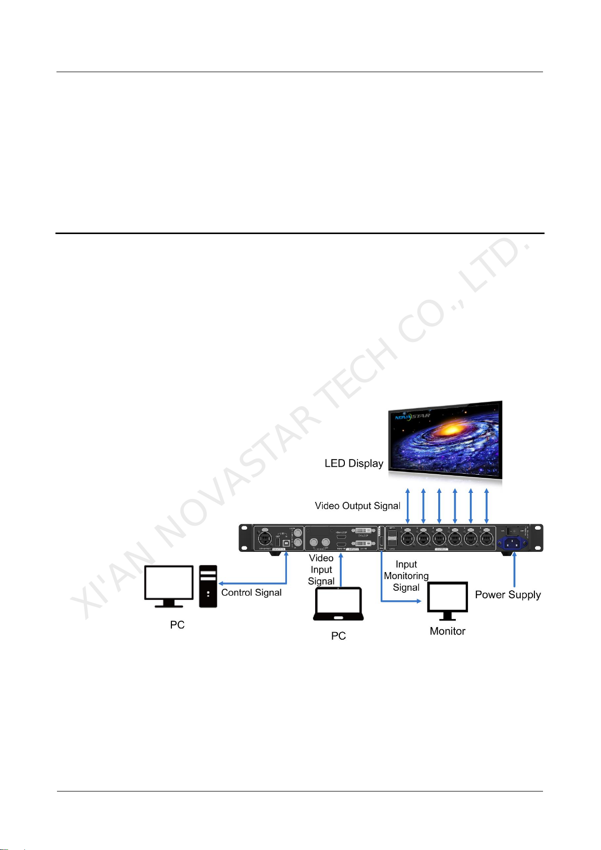
The MCTRL660 PRO can work as a sending card or fiber converter, meeting multiple
application needs.
Scenario 1: Application of Sending Card Mode
On the OLED menu screen, choose Working Mode > Sending Card. This mode
uses the optical ports or Gigabit Ethernet ports to output video signals.
4 Applications
Figure 4-1 Application of sending card mode
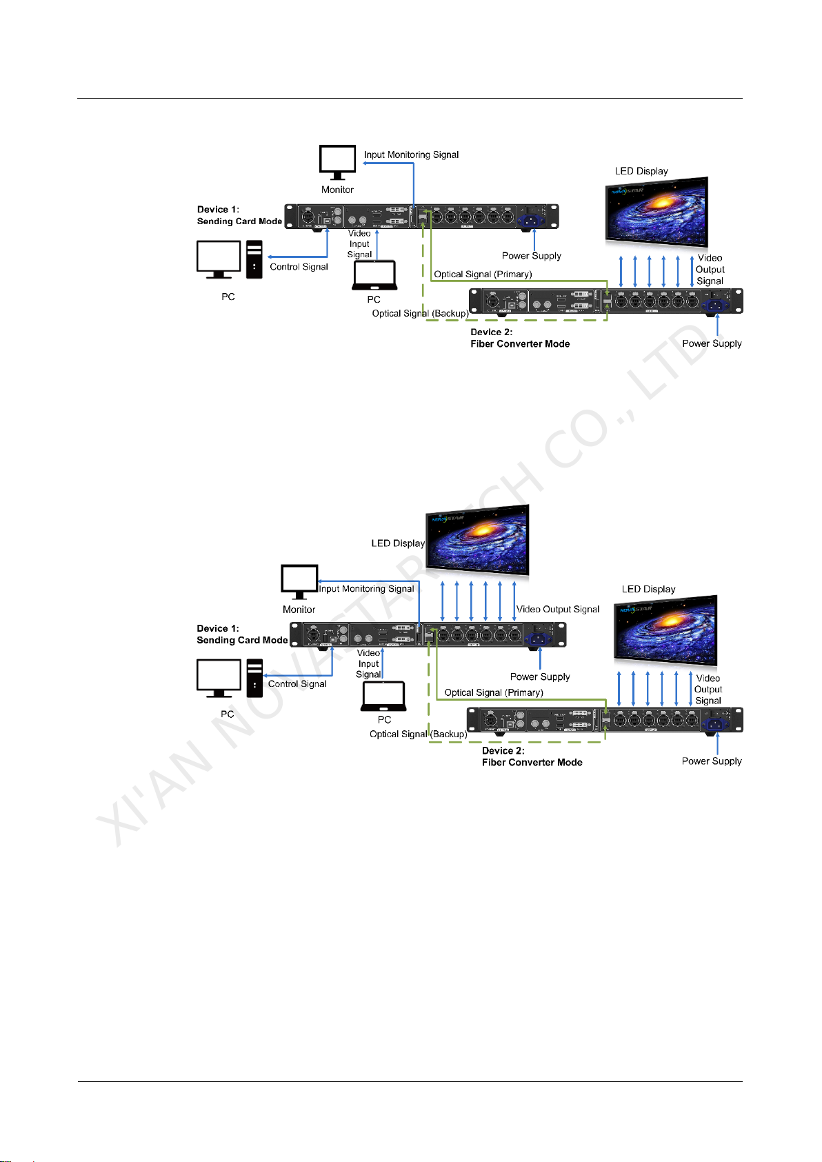
Scenario 2: Application of Fiber Converter Mode
Set the working mode for the two devices respectively, as shown in Figure 4-2.
Device 2 uses the optical ports (for input/output) and Gigabit Ethernet ports (for
output/input) to realize optical and electric signal conversion, which allows for longdistance signal transmission.
Page 11
MCTRL660 PRO Independent Controller
User Manual
4 Applications
www.novastar.tech
6
XI'AN NOVASTAR TECH CO., LTD.
Figure 4-2 Application of fiber converter mode
Scenario 3: Application of Dual-Output Working Mode
Set the working mode for the two devices respectively, as shown in Figure 4-3.
Device 1 uses the optical ports and Gigabit Ethernet ports to output video signals at
the same time.
Figure 4-3 Application of dual-output working mode
Page 12

MCTRL660 PRO Independent Controller
User Manual
5 Cascading Devices
www.novastar.tech
7
XI'AN NOVASTAR TECH CO., LTD.
5 Cascading Devices
The control computer needs to control multiple MCTRL660 PRO devices.
Cascade devices via USB IN and USB OUT ports of the MCTRL660 PRO
devices. Up to 8 devices can be cascaded.
Multiple MCTRL660 PRO devices need to be genlocked.
Cascade devices via GENLOCK IN and GENLOCK LOOP connectors of the
MCTRL660 PRO devices. Up to 8 devices can be cascaded.
Page 13

MCTRL660 PRO Independent Controller
User Manual
6 Hardware Structure
www.novastar.tech
8
No.
Description
1
Operating indicator
2
Standby button
3
OLED operation screen
4
Function knob
5
BACK button: Press to go back to previous menu.
6
INPUT button: Press to choose a video source.
7
USB port: Used to update firmware
Connector Type
Connector Quantity
Connector Name
Input
1
DVI IN
1
HDMI IN
1
3G-SDI IN
XI'AN NOVASTAR TECH CO., LTD.
Appearance
6.1.1 Front Panel
6 Hardware Structure
6.1.2 Rear Panel
Page 14

MCTRL660 PRO Independent Controller
User Manual
6 Hardware Structure
www.novastar.tech
9
Output
6
RJ45 (Gigabit Ethernet ports)
2
OPT1/OPT2 (10G optical ports)
1
DVI LOOP
1
HDMI LOOP
1
3G-SDI LOOP
MONITOR
1
HDMI (Output)
Control
1
GENLOCK IN
1
GENLOCK LOOP
1
ETHERNET (Fast Ethernet port)
1
USB IN
1
USB OUT
Power
1
100 V–240 V AC
XI'AN NOVASTAR TECH CO., LTD.
Dimensions
Unit: mm
Page 15

MCTRL660 PRO Independent Controller
User Manual
7 Home Screen
www.novastar.tech
10
No.
Description
1 1
Device name
2 2
The currently selected input source and its resolution and refresh rate
3 3
IP address
4 4
Different types of video sources and their connection statuses
5 5
Ethernet port connection status
Always on: The Ethernet port connection works and the port serves as master.
Off: The Ethernet port is not connected or the connection does not work.
A mark (not flashing) on top corner of icon: The Ethernet port is in redundancy
status, but the redundancy has not taken effect.
A mark (flashing) on top corner of icon: The Ethernet port is in redundancy
status and the redundancy has taken effect.
6 6
Operating status
/
The system configuration file is backed up/not backed
up.
XI'AN NOVASTAR TECH CO., LTD.
Sending Card Mode
In the sending card mode, the home screen of the MCTRL660 Pro is shown below.
7 Home Screen
Page 16

MCTRL660 PRO Independent Controller
User Manual
7 Home Screen
www.novastar.tech
11
No.
Description
(The voltage and temperature alarm status has the
display priority here.)
/ /
Voltage alarm / Temperature alarm / Voltage and
temperature alarms
(When there are no such alarms, the backup status is
displayed here.)
1–2
Optical port connection status:
Always on: The optical port connection works and the
port serves as master.
Off: The optical port is not connected or the
connection does not work.
/ / /
Connection status of control ports:
Not connected / USB connected / Ethernet connected /
GENLOCK connected
When USB port, Ethernet port and GENLOCK
connector are all connected to the control computer,
their priority in control is GENLOCK > USB >
ETHERNET.
7 7
LED screen brightness
/
Buttons on the front panel are locked/unlocked.
No.
Description
1 1
Device name
2 2
IP address
XI'AN NOVASTAR TECH CO., LTD.
Fiber Converter Mode
In the fiber converter mode, the home screen of the MCTRL660 Pro is shown below.
Page 17

MCTRL660 PRO Independent Controller
User Manual
7 Home Screen
www.novastar.tech
12
No.
Description
3 3
The OPT1 port is the master input/output optical port, corresponding to the 6
Gigabit Ethernet ports. The OPT1 icon has different statuses:
− Always on: The OPT1 port connection works.
− Off: The OPT1 port is not connected or the connection does not work.
4 5
1–6: Indicate Ethernet ports 1–6.
LINK: Ethernet port connection status
The following diamond icon status indicates the Ethernet connection status.
− Always on: The Ethernet port connection works.
− Off: The Ethernet port is not connected or the connection does not work.
ACT: Signal transmission status of Ethernet port
The following diamond icon status indicates the signal transmission status of
Ethernet port.
− Flashing: The Ethernet port is transmitting signals.
− Off: The Ethernet port is not transmitting signals.
5
The OPT2 port works as the backup input/output port of OPT1.
Always on: The OPT2 port connection works.
Off: The OPT2 port is not connected or the connection does not work.
6 6
7
Operating status
/
/ /
Normal voltage and temperature / Voltage alarm /
Temperature alarm / Voltage and temperature alarms
/ /
Connection status of control ports:
Not connected / USB connected / Ethernet connected
When both USB and Ethernet ports are connected to the
control computer, USB port has the priority in control.
/
Buttons on the front panel are locked/unlocked.
XI'AN NOVASTAR TECH CO., LTD.
Page 18

MCTRL660 PRO Independent Controller
User Manual
8 Menu Operations
www.novastar.tech
13
XI'AN NOVASTAR TECH CO., LTD.
The MCTRL660 PRO is powerful and easy to use. You can quickly configure the LED
screen to light it up and display the entire input source following steps in 8.1 Quick
Screen Configuration. With other menu settings, you can further improve the LED
screen display effect.
Instruction on knob operations:
Press the knob to enter a menu page or confirm an operation.
Rotate the knob to select a menu item or adjust a menu parameter.
Hold the knob and BACK button simultaneously for 5 seconds to lock or unlock
all the buttons.
8 Menu Operations
Quick Screen Configuration
Following the steps below, namely Setting Input Source > Setting Input
Resolution > Quickly Configuring Screen, you can quickly light up the LED screen
to display the entire input source.
8.1.1 Step 1 Setting Input Source
Supported input sources include 3G-SDI, Single-Link DVI and HDMI 1.4a. Select an
input source that matches the type of the inputted external video source.
Constraints on input sources:
Only one video input source can be selected at the same time.
Interlaced SDI video sources do not support low latency.
SDI video sources do not support the following functions:
− Color depth adjustment
− Image mirroring
− Contrast, saturation and hue adjustment
Page 19

MCTRL660 PRO Independent Controller
User Manual
8 Menu Operations
www.novastar.tech
14
XI'AN NOVASTAR TECH CO., LTD.
Figure 8-1 Input source settings
Step 1 On the home screen, press the knob to enter the menu.
Step 2 Chose Input Settings > Input Source to enter its submenu.
Step 3 Select the target video source and press the knob to enable it.
8.1.2 Step 2 Setting Input Resolution
Note: SDI input sources do not support input resolution settings.
The input resolution can be set through either of the following methods.
Method 1: Selecting a Preset Resolution
Select an appropriate preset resolution and refresh rate as the input resolution.
Step 1 On the home screen, press the knob to enter the menu.
Step 2 Choose Input Settings > Preset Resolution to enter its submenu.
Step 3 Select a resolution and a refresh rate, and press the knob to apply them respectively.
The MCTRL660 PRO supports the following preset resolutions.
1024×768@(24/30/48/50/60/72/75/85/100/120)Hz
1280×1024@(24/30/48/50/60/72/75/85)Hz
1366×768@(24/30/48/50/60/72/75/85/100)Hz
1440×900@(24/30/48/50/60/72/75/85)Hz
1600×1200@(24/30/48/50/60)Hz
1920×1080@(24/30/48/50/60)Hz
1920×1200@(24/30/48/50/60)Hz
2560×960@(24/30/48/50)Hz
2560×1600@(24/30)Hz
Method 2: Customizing a Resolution
Customize a resolution by setting a custom width, height and refresh rate.
Step 1 On the home screen, press the knob to enter the menu.
Step 2 Choose Input Settings > Custom Resolution to enter its submenu and set the
screen width, height and refresh rate.
Step 3 Select Apply and press the knob to apply the custom resolution.
8.1.3 Step 3 Quickly Configuring Screen
This function is used to quickly configure a screen.
Page 20

MCTRL660 PRO Independent Controller
User Manual
8 Menu Operations
www.novastar.tech
15
Note
a). If n ports are used to load
the screen, the number of
cabinets loaded by each of
the first (n–1) ports must be
the same and the integral
multiple of the number of
cabinet rows or columns, and
it cannot be less than the
number of cabinets loaded
by the last port.
Example:
If all the 6 Ethernet ports are used to load the screen,
the number of cabinets loaded by ports 1–5 must be
the same and the integral multiple of the number of
cabinet rows or columns. Therefore, you need to set
only the number of cabinets loaded by port 1 according
to the actual situation. The number of cabinets loaded
by port 6 must be less than or equal to the number of
cabinets loaded by port 1.
b). Irregular screens must be configured in NovaLCT.
c). Rotate the knob to select the target data flow which can be previewed on the LED
screen in real time and then press the knob to save the one you selected.
d). Ensure that the cabinets loaded by each Ethernet port are connected one by one in
the same direction.
e). Ensure that the Ethernet port 1 is at the beginning position of the whole physical
connection.
XI'AN NOVASTAR TECH CO., LTD.
Figure 8-2 Quick configuration
Step 1 On the home screen, press the knob to enter the menu.
Step 2 Choose Screen Settings > Quick Config to enter its submenu.
Step 3 Enable Quick Config and set the parameters.
Set Cabinet Row Qty and Cabinet Column Qty (number of cabinet rows and
columns to be loaded).
Set Port 1 Cabinet Qty (number of cabinets loaded by Ethernet port 1). The
device has restrictions on the number of cabinets loaded by the Ethernet ports.
For details, see Note a).
Set Data Flow of the screen. For details, see Note c), d), and e).
Brightness Adjustment
Adjust the LED screen brightness value based on the current ambient brightness and
eye comfort. Appropriate brightness can extend life of LEDs in LED screen.
Page 21

MCTRL660 PRO Independent Controller
User Manual
8 Menu Operations
www.novastar.tech
16
XI'AN NOVASTAR TECH CO., LTD.
Figure 8-3 Brightness adjustment
Step 1 On the home screen, press the knob to enter the menu.
Step 2 Select Brightness and press the knob to enter the adjustment status.
Step 3 Rotate the knob to adjust the brightness value. The LED screen displays the
adjustment effect in real time. Press the knob to apply the brightness value.
Screen Settings
Configure the LED screen to ensure the screen can display the whole image
normally.
Screen configuration methods include quick, advanced and auto configurations.
There are constrains on these methods, explained as below.
The three methods cannot be used at the same time.
When you are configuring screen in NovaLCT, the three configuration methods
on The MCTRL 660 PRO are disabled.
8.3.1 Quick Configuration
Configure the whole LED screen uniformly and quickly. For details, see 8.1.3 Step 3
Quickly Configuring Screen.
8.3.2 Advanced Configuration
Set parameters for each Ethernet port, including number of cabinet rows and
columns (Cabinet Row Qty and Cabinet Column Qty), horizontal offset (Start X),
vertical offset (Start Y), and data flow.
Figure 8-4 Advanced configuration
Step 1 On the home screen, press the knob to enter the menu.
Step 2 Choose Screen Settings > Advanced Config to enter its submenu.
Step 3 Enable Advance Config and set the parameters.
Page 22

MCTRL660 PRO Independent Controller
User Manual
8 Menu Operations
www.novastar.tech
17
XI'AN NOVASTAR TECH CO., LTD.
8.3.3 Auto Configuration
Note: Each Ethernet port must load only a whole row or column of cabinets.
Figure 8-5 Each Ethernet port loading only one row of cabinets
Figure 8-6 Each Ethernet port loading only one column of cabinets
Figure 8-7 Auto configuration
Step 1 On the home screen, press the knob to enter the menu.
Step 2 Choose Screen Settings > Auto Config to enter its submenu.
Step 3 Enable Auto Config and select a data flow.
Page 23

MCTRL660 PRO Independent Controller
User Manual
8 Menu Operations
www.novastar.tech
18
XI'AN NOVASTAR TECH CO., LTD.
8.3.4 Image Offset
After configuring the screen, adjust the horizontal and vertical offsets (Start X and
Start Y) of the overall displayed image to ensure it is displayed in the target position.
Figure 8-8 Image offset
Step 1 On the home screen, press the knob to enter the menu.
Step 2 Choose Screen Settings > Image Offset to enter its submenu.
Step 3 Set the Start X and Start Y values.
Input Settings
Set the input source and input resolution.
Input Source Settings
On the OLED menu screen, select an input source that matches the type of the
inputted external video source. Only one video input source can be selected at the
same time. For details, see 8.1.1 Step 1 Setting Input Source.
Input Resolution Settings
Set a preset or custom resolution for the selected input source. For details, see 8.1.2
Step 2 Setting Input Resolution.
Display Control
Control the status of display on the LED screen.
Figure 8-9 Display control
Normal: The LED screen displays the current input source normally.
Black Out: The LED screen goes black and does not display input source still being
played in the background.
Freeze: The LED screen always displays the frame when frozen. The input source is
still being played in the background.
Test Pattern: Test patterns are used to check the display effect and pixel operating
status. There are 8 test patterns, including pure colors and line patterns.
Page 24

MCTRL660 PRO Independent Controller
User Manual
8 Menu Operations
www.novastar.tech
19
XI'AN NOVASTAR TECH CO., LTD.
Step 1 On the home screen, press the knob to enter the menu.
Step 2 Choose Display Control to enter its submenu.
Step 3 Select a control mode and press the knob to apply it.
Image Mirroring
Mirror images displayed on the LED screen. You can disable mirroring, mirror the
image from left to right or from top to bottom. The image mirroring is based on the
entire output image.
Constrain: Image mirroring and low latency cannot be enabled at the same time.
Figure 8-10 Image mirroring
Step 1 On the home screen, press the knob to enter the menu.
Step 2 Select Mirror and press the knob to enter its submenu.
Step 3 Set the mirroring mode for the image loaded by current Ethernet port.
Step 4 (Optional) Select Apply to All Ports and press the knob. The mirroring settings will
take effect on all other Ethernet ports automatically.
The mirroring effects are illustrated in the following figures.
Figure 8-11 Left-right mirroring of the image loaded by Ethernet port 1
As shown above, after you set the mirroring mode as left-right for Ethernet port 1, the
image displayed in the Ethernet port 1 area changed to the left-right mirrored image
of the image loaded by Ethernet port 4. That is to say, the entire image is mirrored
horizontally, but only the Ethernet port 1 area displays the partial mirrored image.
Page 25

MCTRL660 PRO Independent Controller
User Manual
8 Menu Operations
www.novastar.tech
20
XI'AN NOVASTAR TECH CO., LTD.
Figure 8-12 Left-right mirroring of images loaded by Ethernet port 1 and 2
As shown above, after you set the mirroring mode as left-right for Ethernet ports 1-2,
the images displayed in the areas of Ethernet ports 1-2 changed to the left-right
mirrored images of the images loaded by Ethernet ports 3-4. That is to say, the entire
image is mirrored horizontally, but only the areas of Ethernet ports 1-2 display the
partial mirrored images.
Figure 8-13 Left-right mirroring of the entire image
As shown above, after you set the mirroring mode as left-right for Ethernet ports 1-4,
the entire image is mirrored horizontally.
Figure 8-14 Top-bottom mirroring of the image loaded by Ethernet port 1
As shown above, after you set the mirroring mode as top-bottom for Ethernet port 1,
the image loaded by Ethernet port 1 will be mirrored vertically. That is to say, the
entire image is mirrored vertically, but only the Ethernet port 1 area displays the
partial mirrored image.
Page 26

MCTRL660 PRO Independent Controller
User Manual
8 Menu Operations
www.novastar.tech
21
XI'AN NOVASTAR TECH CO., LTD.
Figure 8-15 Top-bottom mirroring of the entire image
As shown above, after you set the mirroring mode as top-bottom for Ethernet ports 1-
4, the entire image is mirrored vertically.
Backup and Restore
Figure 8-16 Backup and restore
Back up the system configuration to the controller.
Restore the system configuration from the controller.
Restore the receiving card configuration from the controller.
Restore the sending card configuration from the controller.
System configuration includes configuration files of the sending card (namely the
controller) and receiving cards.
Advanced Settings
Figure 8-17 Advanced settings
Page 27

MCTRL660 PRO Independent Controller
User Manual
8 Menu Operations
www.novastar.tech
22
XI'AN NOVASTAR TECH CO., LTD.
8.8.1 Mapping Function
When mapping function is enabled, each of the cabinets will display its cabinet No.
and the No. of the Ethernet port that loads the cabinet.
Note: Receiving cards used by the system must support mapping function.
Figure 8-18 Illustration of mapping function
Example: P: 01 indicates the Ethernet port No. #001 indicates the cabinet No.
8.8.2 Loading RCFG Files
Before you begin: Save the cabinet configuration file (*.rcfgx or *.rcfg) to the local PC.
Note: Configuration files of irregular cabinets are not supported.
Step 1 Run NovaLCT and choose Tools > Controller Cabinet Configuration File Import.
Step 2 On the displayed page, select the currently used serial port or Ethernet port, click
Add Configuration File to select and add a cabinet configuration file.
Step 3 Click Save the Change to HW to save the change to the controller.
Page 28

MCTRL660 PRO Independent Controller
User Manual
8 Menu Operations
www.novastar.tech
23
Parameter
Description
Color temperature
Range: 4000 K–9500 K, Stepping: 100
Red
Green
Blue
Range: 0–255, Stepping: 1
Gamma
Range: 1.0–4.0, Stepping: 0.1
Contrast
Range: 0%–100%, Stepping: 1
Saturation
Range: 0%–100%, Stepping: 1
Hue
Range: 0–180, Stepping: 1
XI'AN NOVASTAR TECH CO., LTD.
8.8.3 Alarm Threshold Settings
Set the alarm thresholds for device temperature and voltage. When a threshold is
exceeded, its corresponding icon will be flashing, instead of displaying the value.
Note: When there are no temperature or voltage alarms, the home screen will display
the backup status.
: Voltage alarm, icon flashing. Voltage threshold range: 3.5 V–7.5 V).
: Temperature alarm, icon flashing. Temperature threshold range: -20°C–
85°C).
: Voltage and temperature alarms at the same time, icon flashing.
8.8.4 Image Settings
Adjust the color of parameters of the output image on the LED screen.
Table 8-1 Image parameters
8.8.5 Saving to RV Card
Send and save the configuration parameters of the controller to the receiving cards
and those parameters will not be lost after the controller is powered off.
8.8.6 Redundancy
Set the controller as the primary or backup device. When the controller works as a
backup device, set the data flow direction as opposite to that of the primary device.
If the controller is set as the backup device, when the primary device fails, the backup
device will immediately take over the work of the primary device, that is, the backup
takes effect. After the backup takes effect, the target Ethernet port icons on the home
screen will have marks on top flashing once every 1 second.
8.8.7 Presets
Choose Advanced Settings > Presettings to save current settings as a template.
Up to 10 presets can be saved.
Save: Save current parameters as a preset.
Page 29

MCTRL660 PRO Independent Controller
User Manual
8 Menu Operations
www.novastar.tech
24
Backup No.
Primary Video Source
Backup Video Source
Backup 1
SDI
NULL/DVI/HDMI
Backup 2
HDMI
NULL/DVI/SDI
Backup 3
DVI
NULL/SDI/HDMI
Color Depth of
Input Source
Description
8bit
Input of 8-bit input source does not change the controller's loading
capacity. You cannot perform deep color loop mode adjustment.
10bit
Input of 10-bit input source reduces the controller's loading
capacity by half. You can perform deep color loop mode
adjustment.
XI'AN NOVASTAR TECH CO., LTD.
Load: Read back the parameters from the saved preset.
Delete: Delete the parameters saved in the preset.
8.8.8 Inputs Backup
Set a backup video source for each primary video source. Other input video sources
supported by the controller can be set as backup video sources.
After a backup video source takes effect, the video source selection is irreversible.
Table 8-2 Video source backup
8.8.9 Low Latency
Low latency is used to reduce the time delay between the input of video signal to the
controller and the corresponding output. To enable low latency, you need to set the
horizontal resolution loaded by a single Ethernet port less than or equal to 512 pixels.
Low latency cannot be enabled with any of the following functions at the same time.
Image mirroring
Input of interlaced SDI video sources
GENLOCK
8.8.10 Color Depth
Set the color depth of input source, including 8 bit, 10 bit and 12 bit.
Constraints: SDI video sources do not support adjustment of input color depth.
Figure 8-19 Color depth
Table 8-3 Input color depth adjustment
Page 30

MCTRL660 PRO Independent Controller
User Manual
8 Menu Operations
www.novastar.tech
25
12bit
Input of 12-bit input source reduces the controller's loading
capacity by half. You cannot perform deep color loop mode
adjustment.
XI'AN NOVASTAR TECH CO., LTD.
Video sources with different color depths support different input resolutions. For
details, see 3.2 Video Source Features.
Deep Color Loop Mode Adjust
When multiple MCTRL660 PRO units are cascaded, if the color depth of the output
video source on current device does not match the color depth of the video source
inputted from the previous device, you can select this function on the previous device
to adjust the loop output.
System Settings
Figure 8-20 System settings
Factory Reset
Reset the controller to factory settings.
Go Homepage (s)
Set the time of staying on the current screen before going back to the homepage
when no action is performed. The time range is 30s to 3600s.
OLED Brightness
Adjust the brightness of the OLED menu screen on the front panel.
Hardware Version
Check the hardware version of the controller. If a new version is released, you can
update the firmware programs in NovaLCT or SmartLCT.
Communication Settings
Set the communication mode and network parameters of the MCTRL660 PRO.
Page 31

MCTRL660 PRO Independent Controller
User Manual
8 Menu Operations
www.novastar.tech
26
XI'AN NOVASTAR TECH CO., LTD.
Communication mode: USB preferred and Local Area Network (LAN) preferred
The controller connects to PC via the USB port or ETHERNET port. If USB
Preferred is selected, the PC prefers to communicate with the controller via the
USB port, or else via the ETHERNET port.
Network settings can be manual or automatic.
− Manual settings parameters include controller IP address and subnet mask.
− Automatic settings can read the network parameters automatically.
Reset: Reset the network parameters to default values.
Working Mode
The MCTRL660 PEO allows you to switch between sending card mode and fiber
converter mode.
Sending Card Mode
On the OLED menu screen, set the working mode as Sending Card. Both the optical
ports and Gigabit Ethernet ports can work as output ports to output video signals.
You can refer to Scenario 1: Application of Sending Card Mode. The home screen in
sending card mode is shown below.
Figure 8-21 Home screen in sending card mode
Fiber Converter Mode
Only communication settings and working mode settings are available.
The temperature and voltage alarm ranges are the same as their last settings.
On the OLED menu screen, set the working mode as Fiber Converter. The optical
ports (for input/output) and Gigabit Ethernet ports (for output/input) are used to
realize conversion between optical and electric signals. You can refer to Scenario 2:
Application of Fiber Converter Mode. The home screen in fiber converter mode is
shown below.
Figure 8-22 Home screen in fiber converter mode
Page 32

MCTRL660 PRO Independent Controller
User Manual
8 Menu Operations
www.novastar.tech
27
XI'AN NOVASTAR TECH CO., LTD.
Language
Change the user interface language of the OLED menu screen.
Page 33

MCTRL660 PRO Independent Controller
User Manual
9 Operations on PC
www.novastar.tech
28
XI'AN NOVASTAR TECH CO., LTD.
9 Operations on PC
Individual Gamma Adjustment for RGB
This function can effectively control image non-uniformity under low grayscale and
white balance offset to improve the LED screen's image quality.
Note: Only the A8s receiving card supports this function.
Step 1 Run NovaLCT and choose Brightness > Manually Adjustment.
Step 2 Under Advanced Settings, choose Gamma > Custom Gamma Adjustment and
click Configuration to enter the Gamma Adjustment page.
Step 3 Adjust Red Gamma, Green Gamma and Blue Gamma, respectively.
Step 4 Click Send.
Page 34

MCTRL660 PRO Independent Controller
User Manual
9 Operations on PC
www.novastar.tech
29
XI'AN NOVASTAR TECH CO., LTD.
Operations on Web Page
The MCTRL660 PRO supports screen configuration on web page, allowing for more
convenient screen configuration.
Note:
Operations that cannot be done on web page: backup and restore, loading RCFG
files), presettings, inputs backup, system settings, communication mode settings, and
working mode settings.
9.2.1 Environment Configuration
Step 1 Connect the MCTRL660 PRO to PC (or mobile device).
− Scenario 1: MCTRL660 PRO connected to PC Via Ethernet cable
− Scenario 2: MCTRL660 PRO connected to PC (or mobile device) via router
to the same LAN
Step 2 Set the PC (or mobile device) and the MCTRL660 PRO on the same LAN.
Step 3 Obtain the IP address of the MCTRL660 PRO.
Step 4 On the browser, enter the IP address to enter the operation page.
Note: .Google Chrome is recommended. (Safari browser can also be used on iOS.)
9.2.2 Applications
Scenario 1: MCTRL660 PRO connected to PC via Ethernet cable
Page 35

MCTRL660 PRO Independent Controller
User Manual
9 Operations on PC
www.novastar.tech
30
XI'AN NOVASTAR TECH CO., LTD.
Scenario 2: MCTRL660 PRO connected to PC (or mobile device) via LAN
Software Operations on PC
9.3.1 NovaLCT
Connect the MCTRL660 PRO to the control computer installed with NovaLCT V5.1.0
or later via USB cable to perform screen configuration, brightness adjustment,
calibration, display control, monitoring, etc. For details on their operations, see
NovaLCT LED Configuration Tool for Synchronous System User Guide.
Figure 9-1 User interface of NovaLCT
Page 36

MCTRL660 PRO Independent Controller
User Manual
9 Operations on PC
www.novastar.tech
31
XI'AN NOVASTAR TECH CO., LTD.
9.3.2 SmartLCT
Connect the MCTRL660 PRO to the control computer installed with SmartLCT V3.2.0
or later via USB cable to perform building-block cabinet configuration, seam
brightness adjustment, real-time monitoring, hot backup, etc. For details on their
operations, see SmartLCT User Manual.
Figure 9-2 User interface of SmartLCT
Firmware Update
9.4.1 NovaLCT
In NovaLCT, perform the following steps to update the MCTRL660 PRO firmware.
Step 1 Start NovaLCT and choose User > Advanced Synchronous System User Login
and log in as an advanced user.
Step 2 Type the secret code "admin" to enter the program loading page.
Step 3 Click Browse to select the update program path and then click Update.
9.4.2 SmartLCT
In SmartLCT, perform the following steps to update the MCTRL660 PRO firmware.
Step 1 Start SmartLCT and enter the V-Sender page.
Step 2 In the properties area on the right, click to enter the Firmware Upgrade page.
Step 3 Click to select the update program path.
Step 4 Click Update.
Page 37

MCTRL660 PRO Independent Controller
User Manual
10 Specifications
www.novastar.tech
32
Connector
Type
Connector Name
Description
Input
DVI IN
Single-link DVI connector
Custom resolutions supported:
Maximum horizontal resolution: 3840×600@60Hz
Maximum vertical resolution: 600×3840@60Hz
Supported standard resolutions:
1024×768@(24/30/48/50/60/72/75/85/100/120)Hz
1280×1024@(24/30/48/50/60/72/75/85)Hz
1366×768@(24/30/48/50/60/72/75/85/100)Hz
1440×900@(24/30/48/50/60/72/75/85)Hz
1600×1200@(24/30/48/50/60)Hz
1920×1080@(24/30/48/50/60)Hz
1920×1200@(24/30/48/50/60)Hz
2560×960@(24/30/48/50)Hz
2560×1600@(24/30)Hz
HDMI IN
HDMI 1.4a compliant
HDCP 1.4 compliant
Custom resolutions supported:
Maximum horizontal resolution: 3840×600@60Hz
Maximum vertical resolution: 600×3840@60Hz
Supported standard resolutions:
1024×768@(24/30/48/50/60/72/75/85/100/120)Hz
1280×1024@(24/30/48/50/60/72/75/85)Hz
1366×768@(24/30/48/50/60/72/75/85/100)Hz
1440×900@(24/30/48/50/60/72/75/85)Hz
1600×1200@(24/30/48/50/60)Hz
1920×1080@(24/30/48/50/60)Hz
1920×1200@(24/30/48/50/60)Hz
XI'AN NOVASTAR TECH CO., LTD.
10 Specifications
Page 38

MCTRL660 PRO Independent Controller
User Manual
10 Specifications
www.novastar.tech
33
2560×960@(24/30/48/50)Hz
2560×1600@(24/30)Hz
3G-SDI IN
SMPTE ST 425-1 Level A & B, SMPTE ST 274, ST 296, ST 295
compliant
Maximum supported input resolution: 1920×1080@60Hz
Note: 3G-SDI input sources do not support input resolution
settings.
Output
RJ45 × 6
6 Gigabit Ethernet ports
Maximum loading capacity of a single output: 650 000 pixels
Support redundancy between Ethernet ports.
OPT1
OPT2
10G optical ports
− Single-mode twin-core fiber: Support LC optical connectors;
wavelength: 1310 nm; transmission distance: 10 km;
OS1/OS2 recommended.
− Dual-mode twin-core fiber: Support LC optical connectors;
wavelength: 850 nm; transmission distance: 300 m;
OM3/OM4 recommended.
The maximum loading capacity of a single optical port equals to
that of all the 6 Ethernet ports.
2 OPT inputs/outputs
− The OPT1 works as the primary input or output port, and the
6 Gigabit Ethernet ports work as the corresponding output or
input ports.
− The OPT2 works as the backup input or output port of OPT1.
In the sending card mode, both OPT ports and 6 Gigabit Ethernet
ports can work as output ports to output the same image.
In the fiber converter mode, when the OPT ports work as the
input ports, the 6 Gigabit Ethernet ports work as output ports. Or,
when the 6 Gigabit Ethernet ports work as input ports, the OPT
ports work as output ports.
DVI LOOP
DVI loop output
HDMI LOOP
HDMI loop output
3G-SDI LOOP
SDI loop output
MONITOR
HDMI
Connect to a monitor to monitor the inputs. The monitor output
resolution is 1920×1080@60Hz.
If the input resolution exceeds the monitor resolution, the input will
be automatically scaled in proportion and then displayed on the
monitor starting from its top left.
Control
GENLOCK IN
GENLOCK input connector
Genlock type: Blackburst
Input Genlock sync signal to ensure synchronization and same
refresh rate between the output signals of cascaded MCTRL660
PRO units and the external Genlock input signal.
XI'AN NOVASTAR TECH CO., LTD.
Page 39

MCTRL660 PRO Independent Controller
User Manual
10 Specifications
www.novastar.tech
34
GENLOCK LOOP
Genlock loop output connector. Up to 8 MCTRL660 PRO units can
be cascaded.
ETHERNET
Fast Ethernet port, which connects to PC and supports TCP/IP
USB IN
Input port for cascading devices, or connecting to PC
USB OUT
Output port for cascading devices. Up to 8 MCTRL660 PRO units
can be cascaded.
Power
100 V –240 V AC
Input voltage
100 V–240 V AC
Rated power consumption
20.0 W
Operating temperature
-20°C–60°C
Operating humidity
0% RH–90% RH, non-condensing
Dimensions
482.6 mm × 349.0 mm × 50.7 mm
Net weight
4.6 kg
Space requirement
1U
Packing
Carrying case: 550 mm × 440 mm × 175 mm, white cardboard box
Packing box: 530 mm × 140 mm × 410 mm, craft paper box
Accessory box: white cardboard box
1 × MCTRL660 PRO unit
1 × Ethernet cable (1.5 m)
1 × DVI cable (1.5 m, double magnetic ring design, EMC)
1 × USB cable (1.5 m)
1 × HDMI cable (1.5 m)
1 × Power cord
XI'AN NOVASTAR TECH CO., LTD.
 Loading...