

Bedienungs- und Einbauanleitung D
Operating and installation instructions GB
Notice d’emploi et de montage F
Istruzioni d’uso e di installazione I
Gebruiksaanwijzing en inbouwhandleiding NL
Bruks- och monteringsanvisning S
Instrucciones de manejo e instalación E
Instruções de serviço e de montagem P
Zubehör
Accessories
Accessoires
VSB 120
8 622 402 929 / 04.01 7 606 265 001
D
GB
12 3
45
9
;
:
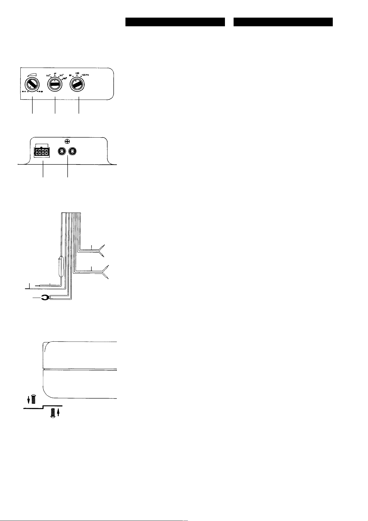
ANSCHLUSS
Der Anschluß 6 rot wird mit plus Batterie, der
Anschluß 7 schwarz mit minus Fahrzeugmasse und der Steueranschluß 8 gelb mit
dem Steuerausgang (z. B. für Electronicantenne o. Verstärker) des Auto-Steuergerätes verbunden. Die Ansteuerung der VSB 120
erfolgt 2kanalig, wahlweise durch die Vorverstärker-Ausgänge oder die Lautsprecher-Ausgänge des Auto-Stereogerätes. Die V orverstärker-Ausgänge werden über eine abgeschirmte Tonleitung an den Cinch (RCA)-Buchsen der
Woofer-Box angeschlossen. Bei Ansteuerung
durch die Lautsprecher-Ausgänge werden die
Eingangsleitungen Pos. 9, : zu den am
nächsten liegenden Lautsprecherkabeln (Front
oder Heck) links und rechts geführt, diese werden aufgetrennt und mit den Eingangsanschlüssen verbunden. Die Polarität der Anschlüsse + oder - ist unbedingt zu beachten.
Auch Brückenendstufen (BTL) können direkt,
ohne zusätzlichen Adapter angeschlossen
werden.
1 Eingangsempfindlichkeit
2 Phasenlage
3 Obere Grenzfrequenz
4 Anschlußstecker
5 Vorverstärker Eingänge
6 + Batterie, rot
7 - Masse, schwarz
8 EIN/AUS Steuereingang, gelb
9 Lautsprecher-Eingang links,
+ grün, -grün/schwarz
: Lautsprecher-Eingang rechts,
+ grau, -grau/schwarz
; Sicherung 7 A
CONNECTIONS
Connect red wire 6 with positive battery, the
black wire 7 with negative v ehicle ground and
the yellow control wire 8 with the control output (e.g. f or electronic aerial or amplifier) of the
car stereo equipment. The VSB 120 has two
drive options, either via the preamplifier output
terminals or the loudspeaker output terminals
of the car stereo equipment. Preamplifier output terminals are connected to cinch (RCA)
jacks of the Woofer Box via a shielded audio
line. When using the loudpeaker output terminals as drive option, run the input leads 9 and
1 to the nearest loudspeaker cables (front or
back) on the left and on the right, separate them
and connect to the input terminals. The polarity of the connections, + or -, must be observed.
Bridge output terminals (BTL), can also be
connected without an additional adaptor.
1 Input sensitivity
2 Phase adjustment
3 Crossover frequency
4 Connection sockets
5 Preamplifier input jacks
6 + battery, red
7 - ground, black
8 ON/OFF control input, yellow
9 Loudspeaker input left,
+ green, - green/black
: Loudspeaker input right,
+ grey, -grey/black
; Fuse 7 A
7
8
6
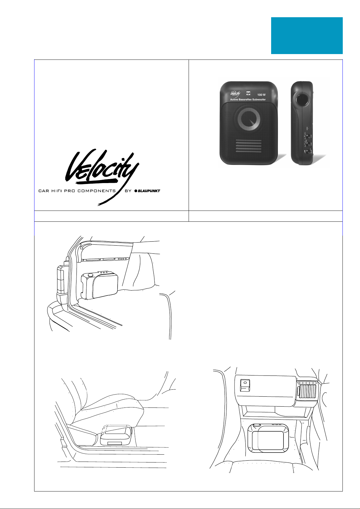
MONTAGE
Mögliche Montageorte richten sich nach der
Art des Fahrzeuges. Erfolgt die Montage direkt auf harten Unterlagen (Seiten-/Bodenblech) empfehlen wir beigefügtes, selbstklebendes Schaumstoffpolster zwischen Gehäuse, Haltewinkel und Montagefläche zu verwenden.
EINSTELLUNGEN
Als Grundeinstellung vor der Inbetriebnahme
empfehlen wir folgende Schalter- und Reglerpositionen: Empfindlichkeit Pos. 1 auf Minimum, Phase Pos. 2 auf 0°, Filter Pos. 3 auf
80 Hz. Schalten Sie die Anlage ein und wählen Sie von Cassette oder CD ein Musikstück
mit ausgeprägter Basswiedergabe. Erhöhen
Sie die Lautstärke an Ihrem Stereogerät bis
zum maximalen unverzerrten Lautstärkepegel. Drehen Sie nun den Empfindlichkeitsregler 1 vorsichtig so weit auf, bis Sie eine
deutliche V erstärkung des Tieftonpegels hören.
Danach wählen Sie mit Schalter 3 eine Filtereinstellung, die Ihnen einen übergangslosen
Höreindruck zwischen den Einbaulautsprechern und dem Woofersystem vermittelt.
Abschließend passen Sie mit Schalter 2 die
Phasenlage so an, daß der Bass druckvoll
klingt und als Schallquelle räumlich, möglichst
nicht mehr geortet werden kann. Überprüfen
Sie Ihre Einstellungen der VSB 120 auch mit
voll aufgedrehtem Bassregler und ggf. eingeschalteter Loudness. Eine Übersteuerung der
ACTIV -WOOFER-BO X durch zu hoch ge wählte Verstärkung (Pos. 1) führ t zu verzerrter
Wiedergabe und kann den Lautsprecher zerstören.
INSTALLATION
Possible positions for installation vary according to the type of car. If installed directly on a
hard base (side or bottom plate), we recommend to use the enclosed, self-adhesive foam
padding between the housing, supporting angle and installation surface.
TUNING
As basic tuning before initial operation we recommend the following switch and control settings: response 1 on minimum, phase 2 on
0°, filter 3 on 80 Hz. Switch on the equipment
and select a piece of music, either on cassette
or CD, with a prominent bass line. Raise the
volume of your stereo equipment until you
reach a maximum volume without distortion.
Now turn up the response control 1 carefully
unitl you hear a distinct increase in the bass
level. By means of switch 3, adjust the filter
so that the acoustic blend of the builtin loudspeakers and the woofer system is unnoticeable. Finally adjust the phase position 2 so
that the bass resonates but cannot be spatially
located as a source of sound. Check y our tuning of the VSB 120 with the bass control fully
turned up and, if necessary, with the loudness
turned on. Overamplification of the ACITVE
WOOFER BOX caused by too high sensitivity
setting 1 leads to distorded reproduction and
can irreparably damage the loudspeaker .

F
I
NL
CONNEXION
Connecter la prise rouge 6 à la batterie (borne
positive), la prise noire 7 à la masse (borne
négative) et la prise de commande jaune 8 á
la sortie de la commande (par. ex pour l’antenne électronique ou ampli) de l’autoradio stéréo. L’e xitation de l’ VSB 120 se f ait à deux voies,
soit par les sorties des préamplificateurs, soit
par les sorties des haut-parleurs de l’autoradio stéréo. Connecter les sorties des préamplificateurs 9, : à l’aide d’une ligne musicale protégée aux prises Cinch (RCA) du
woofer. En cas d’alimentation par les sorties
haut-parleurs, ramener les fils d’entrée aux
câbles des haut-parleurs les plus proches (à
l’avant ou à l’arrière) à droite et à gauche. Les
brancher aux prises d’entrée. Bien respecter
la polarité des connexions. Il est également
possible de connecter directement des sorties
en pont (BTL) sans utiliser un adaptateur
supplémentarie.
1 Sensibilité d’entrée
2 Phase
3 Fréquence limite maximale
4 Connecteur
5 Préamplificateur entrées
6 Batterie (+) rouge
7 Masse (-) noire
8 MARCHE/ARRET entrée d’alimentation,
jaune
9 Haut-parleur, entrée, gauche (+) vert,
(-) vert/noir
: Haut-parleur, entrée, droite (+) gris,
(-) gris/noir
; Fusible 7 A
COLLEGAMENTO
Il cavo 6 rosso viene allacciato al positivo della
batteria, il cavo 7 nero al negativo massa del
veicolo e il cavo di comando 8 giallo all’uscita di comando (per es. per un’antenna elettronica oppure per I’amplificatore) dell’apparecchio di comando dell’automobile.
L’azionamento del VSB 120 a vviene a due canali, a scelta attraverso le uscite del
preamplificatore oppure attraverso le uscite
degli altoparlanti dell’apparecchio stereo dell’autovettura. Le uscite del preamplificatore
vengono allacciate alle prese Cinch (RCA) del
Woofer-Box con l’aiuto di un cavo schermato.
Per l’azionamento attra verso le uscite degli altoparlanti i cavi di ingresso pos. 9, : vengo-
no condotti ai più vicini cavi degli altoparlanti
(parte anteriore o posteriore) a sinistra e a
destra; questi v engono tagliati e collegati ai cavi
di ingresso. La polarità dei cavi + oppure - dev e
essere assolutamente osservata. Anche stadi
implificatori finali possono essere collegati direttamente senza necessità di ulteriori adattatori.
1 Sensibilità di entrata
2 Posizione di fase
3 Frequenza limite superiore
4 Spina di connessione
5 Entrate preamplificatore
6 + batteria, rosso
7 Massa, nero
8 ON/OFF entrata di comando, giallo
9 Entrata altoparlante sinistro,
+ verde, verde/nero
: Entrata altoparlante destro,
+ grigio, grigio/neo
; Fusibile 7 A
AANSLUITING
Aansluiting 6 rood wordt v erbonden met plus
accu, aansluiting 7 zwart met min voertuigmassa en stuuraansluiting 8 geel met de
stuuruitgang (b.v. voor elektrische antenne of
versterker) van de autoradio . De aansturing v an
de VSB 120 geschiedt 2kanaals, naar keuze
via de voorversterker- of via de luid-sprekeruitgangen van de autoradio. De v oorversterkeruitgangen worden via een geïsoleerde
audiokabel aangesloten op de Cinch(RCA)aansluitingen va de wooferbox. Bij aansturing
via de luidsprekeruitgangen worden de
ingangskabels pos. 9, : naar de dichtstbij
gelegen luidsprekerkabels (voor of achter) links
en rechts gevoerd, deze w orden opgesplitst en
op de ingangen aangesloten. De polariteit van
de aansluitingen + of - dient strikt in acht te
worden genomen. Ook brugeindtrappen (BTL)
kunnen direct zonder extra adapter worden
aangesloten.
1 Ingangsgevoeligheid
2 Faseligging
3 Bovenste grensfrequentie
4 Aansluitsteker
5 Voorversterkeringangen
6 + accu, rood
7 - massa, zwart
8 AAN/UIT stuuringang, geel
9 Luidsprekeringang links,
+ groen, -groen/zwart
: Luidsprekeringang rechts,
+ grijs, -grijs/zwart
; Zekering 7 A
MONTAGE
Les emplacements pour le montage dépendent
du type de véhicule. En cas d’un montage effectué directement sur un support dur (tôle latérale ou de fond), nous vous conseilons d’utiliser les plastiques alvéolaires auto-collantes
jointes, entre la carrosserie, l’equerre et la surface de montage.
REGLAGES
Nous vous conseillons comme réglage de base
avant la mise en service les positions suivantes: Sensibilité position 1 au minimum, phase
position 2 sur On, filtre position 3 sur 80 Hz.
Aprés la mise en service sélectionner á partir
du CD ou de la cassette un morceau de musique ayant des graves profonds. Augmenter le
volume sonore jusqu’au niveau maximale sans
aucune défor. Régler le bouton de sensibilité
1 progressivement jusqu’à ce que vous entendiez un renforcement sensible des graves.
Adopter ensuite au moyen du bouton 3 un
réglage de filtre de sorte que l’équilibrage audible entre les haut-parleurs et le systéme woofer
soit parfaitement égal. Ajuster au moyen du
bouton 2 les phases de telle maniére que les
basses soient puissantes et qu’il soit de préférence impossible de localiser la source sonore.
Vérifier les réglages VSB 120 en tournant à
fond le bouton de réglage des grav es et, le cas
échéant, avec un loudness activé. Une suralimentation du WOOFER A CTIV due à une amplification trop 1 élevée a pur conséquence
une déformation acoustique de la réproduction
sans parler du risque d’endommagement du
haut-parleur.
MONTAGGIO
Possibili luoghi per il montaggio dipendono dal
tipo di autovettura. P er il caso che il montaggio
avvenga direttamente su una base dura (lamiera laterale/del pavimento) consigliamo di
usare le spugnette autoadesive fornite da mettere fra la carcassa, I’angolare di supporto e la
superficie di montaggio.
IMPOSTAZIONI
Come regolazione base prima della messa in
funzione consigliamo le seguenti posizioni per
gli interruttori e regolatori: Sensibilità pos. 1
su minimo, fase pos . 2 su 0°, filtro pos. 3 su
80 Hz. Inserite I’impianto e scegliete un brano
musicale su cassetta o CD con i toni bassi
molto accentuati. Alzate il volume del vostro
apparecchio stereo fino al livello massimo riprodotto senza distorsioni. Adesso alzate con
cautela il regolatore di sensibilità 1 finché
percepiate una chiara accentuazione delle
basse frequenze. Quindi scegliete con l’interruttore 3 una regolazione filtro che vi offre
una percezione acustica armonica tra gli altoparlanti integrati ed il sistema Woofer. Infine
adattate la posizione di fase con l’interruttore
2 in modo tale che i bassi abbiano un suono
pieno, ma non possano più essere individuati
direttamente come sorgente sonora. Controllate le vostre impostazioni del VSB 120 anche
con il regolatore dei toni bassi al massimo ed
eventualmente avendo anche il Loudness inserito. Una sovramodulazione del ACTIVWOOFER-BOX do vuta ad un’eccessiva amplificazione (pos. 1 porta ad una r iproduzione
distorta e può distruggere gli altoparlanti.
MONTAGE
De inbouwplaats hangt af van het soort voertuig. Bij montage direct op een harde
onderground (zij- of bodemplaat) is het raadzaam tussen behuizing, montagehoek en
montagevlakken het meegeleverde, zelf-klevende schuimstofkussen te gebruiken.
INSTELLINGEN
Raadzaam als basisinstelling zijn de volgende
schakelaar- en regelaarstanden: gevoeligheid
pos. 1 op minimum, fase pos. 2 op 0°, filter
pos. 3 op 80 Hz. Schakel de installatie aan
en kies een cassette- of CD-titel met een duidelijke basweergav e . Verhoog het volume aan
uw stereo-toestel tot het maximale
onvervormde volumeniv eau. Draai vervolgens
de gevoeligheidsregelaar 1 v oorzichtig zo ver
open tot u een duidelijke versterking van de
lage tonen hoort. Kies vervolgens met schakelaar 3 en filterinstelling di u qua klankindruk
een glijdende overgang tussen de inbouwluidsprekers en het woofersysteem geeft. Ter
afsluiting past u met schakelaar 2 de faseligging zo aan, dat de bas krachtig en als klankbron ruimtelijk klinkt, indien mogelijk zo dat het
lijkt alsof het geluid niet uit een bepaalde richting komt. P as op! Controleer uw instelling v an
de VSB 120 ook met vol opengedraaide basregelaar en ev. ingeschakelde loudness. Een
oversturing van de actiev e wooferbo x door een
te hoog gekozen versterking (pos. 1) leidt tot
vervormde klankweergave en kan de luidspreker beschadigen.

S
E
P
INKOPPLING
Ledningen 6 röd ansluts till bilbatteriets pluspol, ledningen 7 svart till bilens chassie och
styrledningen 8 gul till bilstereons styrutgång
(t ex för auto-matantenner och förstärkare). Den
tvåkanaliga signalmatningen till VSB 120 sker
antingen via bilstereons lågnivåutgång eller
högtalarutgångar. När lågnivån användes kopplas signalerna med en skärmad ledning till
Cinch (RCA)-kontakterna på Woofer-boxen.
När signalmatning sker via högtalarutgångarna
skall ledningarna 9 och : anslutas till de
närmaste högtalar-ledningarna (fram eller bak)
höger och vänster. Var noga med polariteten +
och - på högta-larledningarna. Anslutning till
högtalar-ledningarna kan ske direkt även om
dessa är inkopplade på bryggkopplade slutsteg.
1 Ingångskänslighet
2 Fasläge
3 Övre brytfrekvens
4 Anslutningskontakt
5 Lågnivåingång
6 + batteri, röd
7 - chassie, svart
8 Till/från-styringång, gul
9 Högtalaringång vänster,
+ grön, -grön/svart
: Högtalaringång höger,
+ grå, -grå/svart
; Säkring 7 A
CONEXIÓN
Conectar la línea roja 6 al polo positivo de la
batería, la línea negra 7 a masa del automó-
vil y al línea de control amarilla 8 a la salida
de mando (p.ej. para una antena motorizada o
un amplificador) del equipo estereofónico. El
VSB 120 facilita dos opciones de accionamiento: bien a través de las salidas del
preamplificador, bien por vía de los terminales
altoparlantes del equipo estereofónico. Las
salidas preamplificadoras son conectadas a las
tomas Cinch (RCA) del Woofer a través de un
cable blindado. Para el accionamiento por vía
de los terminales altoparlantes, colocar las líneas de entrada 9 y : a los cables de altavoces más próximos (delantero o transero) al
lado derecho o izquierdo, separarlos y conectarlos a los terminales de entrada. La polaridad de las conexiones + o - debe ser considerada. Los terminales de amplivicatión en puente también pueden ser conectados sin adapter
adicional.
1 Sensibilidad de entrada
2 Ajuste de fase
3 Frecuencia de transición
4 Tomas de conexión
5 Tomas de entrada preamplificadora
6 + batería, rojo
7 - masa, negro
8 ON/OFF entrada de mando, amarillo
9 Entrada altavoz izquierda,
+ verde, - verde/negro
: Entrada altavoz derecha
+ gris, - gris/negro
; Fusible 7 A
CONEXÃO
A conexão 6 vermelha é ligada ao o pólo
positivo da bateria, a conexão 7 preta ao pólo
negativo da massa do automóvel e a cone xão
de comando 8 amarela à saida de comando
(por exemplo para antena eléctrica ou amplificador) do aparelho de comando do automóvel. O comando de VSB 120 é f eito atra vés de
2canais com as saídas do pré-amplificador ou
através das saídas do aparelho Stereo do automóvel. As saídas do pré-amplificador sao
conectadas através de um cabo de som às
tomadas Cinch (RCA) na caixa do Woof er. P ara
o comando através das saídas de altifalantes
os cabos de entrada positivos 9, : devem
ser conduzidos para os cabos de altifalantes
mais próximos (dianteiros ou traseiros) da esquerda e da direita. Estes serão então separados e conectados com as conexões de entradas. A polaridade das cone xões + e - dev e ser
considerada. T ambém amplificadores em ponte
(BTL) podem ser conectados directamente
sem adaptador separado.
1 Sensibilidade de entrada
2 Posição de fases
3 Frequência limite máxima
4 Ficha de conexão
5 Entradas de pré-amplificador
6 + bateria, vermelha
7 Massa, preta
8 Entrada de comando ligard desligar,
amarela
9 Entrada de altifalante esquerda,
+ verde, -verde/preta
: Entrada de altifalante direita,
+ cinza, -cinza/preta
; Fusível 7 A
MONTERING
Möjliga placeringar beror på biltypen. Om
monteringen sker på på hårda underlag rekommenderar vi att den bifogade, självhäftande
skumgummiplattan används mellan hölje, fästvinklar och monteringsytan.
INSTÄLLNINGAR
Innan du startar anläggningen bör du ställa in
följande grundinställning: Känslighet pos 1 på
minimúm, Fas pos 2 på 0°, Filter pos 3 på
80 Hz. Nu startar du anläggningen och väljer
ut ett baskraftigt musikstycke från kassett eller
CD. Öka nu ljudstryrkan, med bilstereons volym-kontroll, så högt som möjligt utan att dis-
torsion uppträder. Vrid nu försiktig på känslighets-kontrollen 1 så att du hör en tydlig höjning av basåtergivningen. Därefter väljer du
med omkopplaren 3 den filterinställning som
ger den bästa övergången mellan de vanliga
högtalarna och Woofern. Avslutningsvis kontrollerar du vilket läge på fasomkopplaren 2
som låter bäst, basen skall vara så fyllig som
möjligt och helst inte vara möjlig att riktningsbestämma. K ontrollera att dina inställningar av
VSB 120 låter bra även när du har maximal
bas och Loudness på din bilstereo. Överstyrning av ACTIVE-WOOFER-BOX, genom för
högt vald känslighet 1, medför distorderat ljug
och risk för högtalarhaveri.
MONTAJE
Los lugares de montaje posibles dependen del
tipo de automóvil. Si se monta el equipo directamente sobre una superficie dura (placa lateral o de fondo) recomendamos colocar los acolchados auto-adhesivos adjuntos de material
alveolar entre la caja, los ángulos de soporte y
la superficie de montaje.
AJUSTE
Recomendamos los siguientes ajustes básicos
para los interruptores y reguladores antes de
poner el equipo en funcionamiento: Sensibilidad 1 en mínimo, fase 2 en 0°, filtro 3 en
80 Hz. Conectar el equipo y seleccionar un título de cassette o CD con graves fuertes. Aumentar el volumen de su equipo estereofónico
hasta obtener el nivel máximo sin
distorsiones. Luego gir ar el regulador de sensibilidad 1 cuidadosamente en sentido horario hasta que se oye una clara acentuación de
los graves . Entonces utilizar el conm utador 3
para seleccionar un ajuste del filtro que le proporciona una acústica harmonica entre los altavoces y el sistema Woofer. Finalmente, regular la posición de fase utilizando el conmutador 2 de manera que se producen graves
bien acentuados que no pueden ser localizados como fuente sonora separada. V erificar los
ajustes del VSB 120 también con el regulador
de graves puesto en máximo y, si es necesario, con el Loudness conectado. Una
sobremodulación del ACTIVE W OOFER BOX
debido a una amplificación excesiva 1 puede resultar en una reproducción distorsionada
o incluso deteriorar el altavoz.
MONTAGEM
Os locais de montagem possíveis dependem
do tipo de automóvel. Se montar directamente
sob uma superfície dura (sob metal no chão
ou em paredes) recomendamos utilizar os
estofamentos de material alveolar entre a caixa, o ângulo de suporte e a superfície de montagem.
AJUSTES
Recomendamos os seguintes ajustes básicos
para as posições de interruptores e reguladores antes de ligar o aparelho: Sensibilidade 1
no mínimo, fase 2 em 0°, filtro 3 em 80 Hz.
Ligue o equipamento e seleccione um título
de cassete ou CD com graves f ortes. A umente
o volume de som no seu aparelho Stereo até
o nível mais alto sem distorção. Gire então o
regulador de sensibilidade 1 cuidadosamente até ouvir uma amplificação nítida do nível
de graves. Seleccione então com o interruptor
3 um ajuste de filtro que Ihe proporcione uma
impressão acústica sem transição entre
altifalantes e sistema de Woofer. Em seguida
ajuste com o interruptor 2 posição de fase
de modo que os graves sejam pressionantes
e não possam ser localizados como fonte de
som. Controle os ajustes do VSB 120 também
com o regulador de graves no máximo ou
Loudness ligado. Uma sobrecarregação do
ACTIV-WOOFER-BOX devido à uma amplificação muito alta (pos 1) leva a uma reprodu-
ção distorcida e pode danificar os altifalantes.
8 622 402 929
 Loading...