

Amplifi er
THA 475 PnP
7 607 792 130
www.blaupunkt.com
THA 475 PnP
ENGLISH ................................................. 3
Installation drawings .................................... 12
中文 ......................................................... 5
安裝圖 ............................................................ 12
한국어한국어 ...................................................... 8
설치 그림 ....................................................... 12
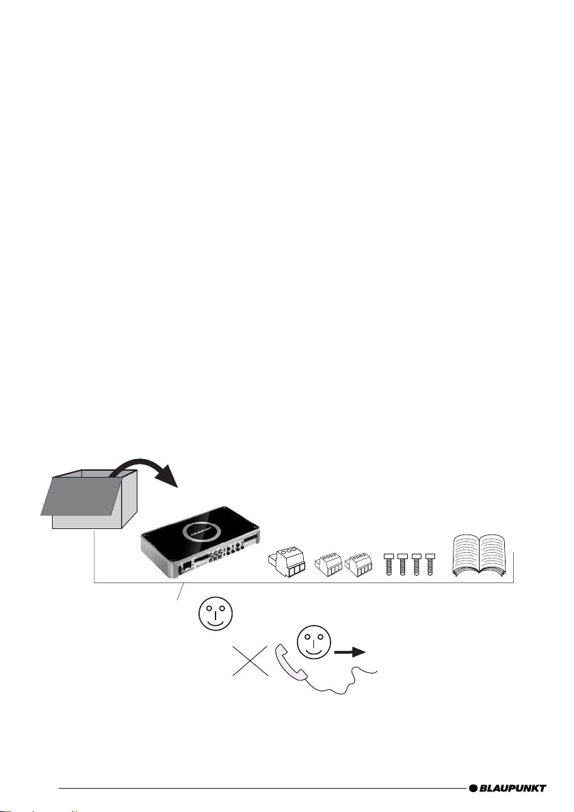
Scope of delivery, 交貨內容, 배송 범위배송 범위
OK
OK
?
?
Spezialist dealer
專業經銷商
전문 대리점
2
THA 475 PnP
ENGLISH
Warranty
We provide a manufacturer warranty for our products
bought within the European Union. You can view the
warranty terms at www.blaupunkt.de or request them
directly from:
Blaupunkt GmbH
Hotline
Robert-Bosch-Str. 200
D-31139 Hildesheim
Germany
Recommendation:
The performance of an amplifi er can only be as good
as its installation. A correct installation increases the
overall performance of your car sound system. The THA
amplifi er should be installed by a trained person. If you
would to install it yourself, please read these installation
instructions very carefully and allow yourself suffi cient
time for the installation.
In conclusion, allow us a few words about the topic of
health protection:
During the playback of music in your vehicle, please
consider that continuous sound-pressure levels above
100 dB can lead to permanent damages to the human
ear and even to loss of hearing. Using today's highperformance systems and loudspeaker confi gurations
allows for reaching sound-pressure levels above 130
dB.
Safety notes
Please observe the following safety notes
during the installation and connection.
- Disconnect the negative pole of the battery! Observe
the safety notes of the vehicle manufacturer.
- When you drill holes, ensure that you do not damage
any vehicle components.
- The cross section of the plus and minus cable may
not be less than 1.5 mm
- Use cable glands for holes with sharp edges.
- An incorrect installation can result in malfunctions
of the electronic vehicle systems or your car sound
system.
Installation and connection instructions
With respect to accident safety, the THA 475 PnP must
be secured in a professional way.
When selecting the installation location, select a dry
location that offers suffi cient air circulation for cooling
the amplifi er.
The installation surface must be suitable to accept the
accompanying screws and provide a fi rm support.
2
(A.W.G. 16).
The amplifi er power cable must be fi tted with a
fuse no more than 30 cm from the battery (see Fig. 2a)
to protect the vehicle battery in case of a short circuit
between power amplifi er and battery. The fuse of the
amplifi er protects only the amplifi er, not the vehicle
battery.
Use loudspeakers with 2-4 Ω impedance (see table or
installation drawing). Observe the maximum power
handling capacity (music output). Do not connect
loudspeakers to earth, use only the referenced
terminals.
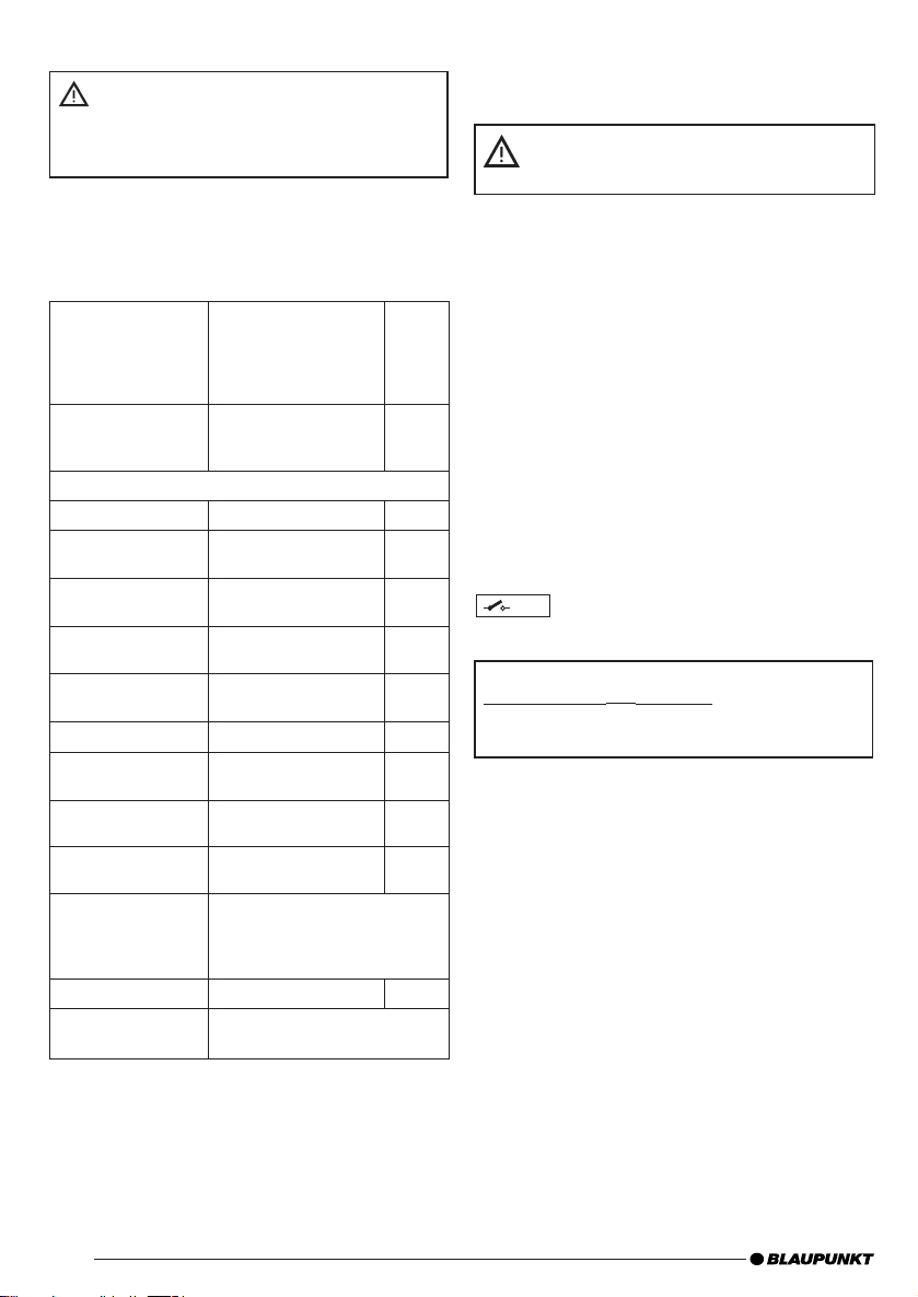
Application options and loudspeaker connection:
Stereo mode
Max power
Max power
RMS power
RMS power
Bridge mode
Max power
RMS power
RMS power acc. to CEA-2006 ( <1% HD/+14.4 V)
Frequency
response
Signal-to-noise
ratio
Signal-to-noise
ratio
Distortion factor
(RMS)
Stability
Input sensitivity
Input sensitivity
Direct AUX IN
Low-pass fi lter
(Low Pass)
High-pass fi lter
(High Pass)
Inputs
Outputs
Dimensions
W x H x D (mm)
4 x 150 Watt / 4 Ω
4 x 170 watt / 2 Ω
4 x 75 watt / 4 Ω
4 x 85 watt / 2 Ω
2 x 360 watt / 4 Ω
2 x 180 watt / 4 Ω
10 Hz - 30,000 Hz
> 95 dB @ RMS power
> 78 dB @ 1 w/ 1 kHz
< 0.05%
2 Ω (4 Ω in bridge
mode)
0.3 - 8 V
0.3 V
50-250 Hz
10-250 Hz
4 x Cinch/RCA,
4 x HighLevel speaker PnP
2 x Direct Aux inputs, 3.5 mm
stereo
4 x loudspeaker
285x42x160 (11.2"x1.7"x6.3")
Fig. 4
Fig. 4
Fig. 5
Fig. 5
3
THA 475 PnP
Plus / minus connection
- We recommend a minimum cross section of 1.5 mm2.
The 12-V continuous positive cable must
be connected with the amplifier + cable at
the vehicle adapter cable (7 607 622 ...)
(see Fig. 7).
- Route a commercially available positive cable to the
battery and connect it via fuse holder 30 cm from
the battery.
- Use cable glands for holes with sharp edges.
- Securely fasten commercially available minus cables to
a noise-free earth point (chassis screw, chassis metal)
(not to the minus pole of the battery).
- Scrap the contact surfaces of the earth point until
they are bright and grease with graphite grease.
Integrated fuses (Fuse)
The fuses integrated in the amplifi er protect the power
amplifi er and the entire electrical system in case of an
error. If a replacement fuse is used, never bridge fuses
or replace them with a type with higher current.
Connection examples
Connection of the voltage supply ............. Fig. 2, 2a, b
Connection to car sound system
with cinch output ..................................... Fig. 3
Loudspeaker connections ....................... Fig. 4/5
Direct Aux Input........................................ Fig. 6/6a
Direct Aux Input connection
Connection option in case of missing or occupied
AUX input at the car sound system
Various NF sources, such as an MP3 player or
a mobile navigation, can be directly connected
via a 3.5-mm jack plug at the Direct Aux Input.
All signal sources can be listened to at the same
time and their volume is adjusted at the respective source device.
Note:
All NF sources must be switched off during in-
stallation and connection!
Installing the jack plug cable
Please use our 5-m jack plug cable with order
number 7 607 001 525 for the connection.
One of its special features is an on/off switch.
Switch position OFF (•):
For installation and deinstallation and no connected NF source.
Switch setting ON: (I / II):
Only after an NF source has been connected.
Caution:
For the connection, always adjust the volume
control to minimum and switch off the amplifi er.
If you want to listen to one sound source via
the front and rear loudspeakers, you must connect the Direct Aux inputs with our Y jack plug
cable (7 607 001 524), (see Fig. 6).
Remote connection of the amplifi er with
+12V
switchable +12 V voltage source.
This allows the amplifi er to be switched on and off using
the on/off-switch of the radio device.
Note:
If the connection is made using a PnP-INPUT cable,
the switch-on is performed automatically.
! As a special feature, +12 V/200 mA are now available
as output switching voltage at the remote input/output after automatic switch-on.
High-level connections (via PnP High-Inputcable
only)
The amplifi er features high-level connections (High
Input) to be able to connect to radio devices without prestage outputs (Fig. 2). This allows for a direct connection
at the loudspeaker output of the radio device.
Note:
Unused Out/Input connectors from the PnP cable must
be connected (see Fig. 2a *).
4
Level control
The Level control is used to adjust the input sensitivity
of the power amplifi er to the output voltage of your car
sound system.
The adjustment range is from 0.3 V to 8 V.
A few important explanations in this context:
By turning the control clockwise, the input sensitivity of
the amplifi er and, therefore, also the volume increases.
However, this is not a volume control; no further amplifi er
output can be achieved in the end position, even if it
may sound like that at the beginning. The system merely
increases the volume faster if the volume control of the
car sound system is turned up.
Loudspeaker connections
(If the amplifi er is to be jumpered, continue with the
section "Bridged loudspeaker connections" at this
point).
As with every audio component, the correct polarisation
of amplifi er and loudspeakers is of essentially importance
for a good bass response. For this reason, ensure that
the positive (+) connection of the amplifi er is connected
with the positive connection (+) of the loudspeaker; the
same applies to the negative (-) connections. In addition,

THA 475 PnP
the left amplifi er channel must be connected with the
left loudspeaker and the right amplifi er channel with
the right loudspeaker.
Bridged loudspeaker connections
Note: Not possible for connection via PnP cable.
The THA 475 PnP amplifi er allows for switching the
channels 1+2 and 3+4 as bridge connection. This allows
the amplifi er to be used for one or several subwoofers
or a mid-range driver. In this confi guration, the amplifi er
combines the right and left channel to a single-channel
output (mono output).
Note:
The amplifi er can add the right and left signal information
only if the right as well as the left RCA connection were
carried out.
Caution:
In a bridge circuit, the amplifi er load must be 4 ohm
or higher. A lower load leads to an overheating or
switch-off of the amplifi er and can cause permanent
damages.
Adjusting the type and range of the frequency
crossovers
With the THA 475 PnP, the type of frequency crossover
(i.e. "Low Pass" or "Hi-Pass") and the desired crossover
frequency can be adjusted. For example, if a pair of
subwoofers is to be connected, low-pass settings are
required. The crossover frequency is dependent upon the
frequency range of the loudspeakers (see recommended
frequency range of the loudspeakers).
High-Pass
At a setting of 250 Hz, the amplifi er has a frequency
range of 250 Hz to 30,000 Hz.
Low-pass frequency control
This control is active if the switch is in the position
"Low-Pass", and allows for setting the desired crossover
frequency.
Example:
At a setting of 150 Hz, the amplifi er has a frequency
range of 10 Hz to 150 Hz.
Radio detection - Auto Remote
With a connection via a PnP INPUT cable, the amplifi er is automatically switched on (Auto Remote func-
tion). A remote connecting cable is not needed!
Power-on indicator (POWER / PROTECTION)
Green LED:
Output stage on, regular operating status.
Red LED:
Output stage is electronically switched off due to an
error.
Recycling and disposal
Please use the return and collection systems
available to dispose of the product.
Subject to changes.
中文
擔保
我們對在歐洲聯盟內購買的本公司產品提供廠家擔保。您可
以在 www.blaupunkt.de 閱讀有關擔保條款或直接向以下
地點索取:
Blaupunkt GmbH
Hotline
Robert-Bosch-Str. 200
D-31139 Hildesheim
Germany
建議:
擴音器的性能好壞完全基於安裝的好壞。正確的安裝增加您
汽車音響系統的整體性能。THA 擴音器應該由受過專門訓
練的人員進行安裝。如果您要自行安裝,請細讀此安裝說明
書並讓您有充足時間進行安裝。
作為總結,請讓我們略談保健此課題:
當在您的汽車內播放音樂時,請顧慮持續高於 100 分貝的
聲壓水平可以對人類的耳朵造成永久性的傷害,甚至失聰。
運用當今的高性能系統和擴音器配置可讓聲壓水平達到 130
分貝以上。
安全備註
請在進行安裝和連接時遵守以下安全備註。
- 拆開電池的負極!請遵守汽車廠商的安全備註。
- 當您鑽孔時,請確保您沒有損壞任何一件汽車組件。
- 正與負電纜的橫截面不可少過 1.5 平方毫米(美國線規
16)。
- 對於有鋒利邊緣的孔,請使用電纜襯墊。
- 不正確的安裝可以導致電子汽車系統或您的汽車音響系統
發生故障。
安裝和連接指示
為確保意外發生時的安全,THA 475 PnP 必須以專業的方
法鎖定。
當選擇安裝位置時,請選擇一個乾爽的位置以便在冷卻擴音器
時能夠提供足夠的空氣環流。
有關安裝表面必須適合鎖上配備的螺絲,同時能夠給於穩固的
支撐。
5
THA 475 PnP
擴音器的電源電纜在離開電池不超過30釐米的位置必
須裝上一個保險絲(請看圖 2a)以便在功率放大器和電池
之間發生短路時保護汽車電池。擴音器的保險絲只保護擴
音器,並沒有保護汽車電池。
使用 2-4 Ω 阻抗的喇叭(看製錶或安裝圖)。遵守功率電
容的最大極限(音樂輸出)。不要把喇叭接地,只使用參考端
子。
應用選項和喇叭連接:
立體音響模式
最高功率
最高功率
均方根值功率
均方根值功率
電橋模式
最高功率
均方根值功率
按照 CEA-2006 的均方根值功率 ( <1% HD / +14.4 伏特)
頻率反應
信噪比
信噪比
失真係數(均方根
值)
穩定性
輸入敏感度
輸入敏感度
直接 AUX IN
低通濾波器
(低通)
高通濾波器
(高通)
輸入
輸出
尺寸
寬 x 高 x 深(毫米)
4 x 150 瓦特 / 4 Ω
4 x 170 瓦特 / 2 Ω
4 x 75 瓦特 / 4 Ω
4 x 85 瓦特 / 2 Ω
2 x 360 瓦特 / 4 Ω
2 x 180 瓦特 / 4 Ω
10 赫茲至 30,000 赫茲
> 95 分貝 @ 均方根
值功率
> 78 分貝 @ 1 瓦 / 1
千赫
< 0.05%
2 Ω (4 Ω 於電橋模
式內)
0.3 至 8 伏特
0.3 伏特
50-250 Hz
10-250 Hz
4 x 非平衡式/RCA
4 x 高電平揚聲器 PnP
2 x 直接輔助輸入,3.5 毫米
立體音響
4 x 喇叭
285x42x160 (11.2"x1.7"x6.3")
圖 4
圖 4
圖 5
圖 5
正/負連接
- 我們建議至少 1.5 平方毫米的橫截面。
12 伏特連續正極電纜必須使用擴音器 + 電纜連接至
汽車適配器電纜(7 607 622 ...)(看圖 7)
- 接駁商用的正極電纜至電池並經由離電池 30 公分的保險
絲支架連接。
- 對於有鋒利邊緣的孔,請使用電纜襯墊。
- 紮牢商用負極電纜至無噪聲的接地點(底盤螺旋、底盤金
屬)(不是至電池的負極)。
- 敲打接地點的接觸表面直到光亮並以石墨脂潤滑。
綜合保險絲(保險絲)
發生誤差時,綜合在擴音器內的保險絲保護功率放大器和整
個電氣系統。如果使用替換保險絲,請勿橋接保險絲或以更
高電流類型的保險絲替代。
連接例子
電壓供應的連接 ..........................................................圖 2, 2a, b
以非平衡式輸出連接至汽車音響系統 ...............圖 3
喇叭連接 .......................................................圖 4/5
直接輔助輸入 ................................................圖 6/6a
以可變換 +12 伏特電壓電源遠程連接擴音器。
+12V
如此,擴音器可使用收音機裝置的開關鈕打開和關閉。
備註:
如果連接使用的是PnP輸入電纜,擴音器將自動開啟。
! 作為特別功能,現有 +12 伏特/200 毫安培作為遙程輸
入/輸出在自動啟動後的輸出切換電壓。
高電平連接(只經由PnP高輸入電纜)
擴音器高電平連接(高輸入)的特色是可以連接至收音機
而無需前置級輸出(圖 2)。這允許收音機設備的喇叭輸出
的直接連接。
備註:
從 PnP 電纜沒被使用的輸出/輸入連接器必須被連接。(看
圖 2a *)
6

直接輔助輸入連接
在汽車音響系統輔助輸入從缺或佔用時的連接選項
各式 NF 源,有如 MP3 播放器或流動導航,可於直
接輔助輸入經由 3.5 毫米的插頭直接連接。所有信
號源可於同時間被收聽,它們的音量也可在各別音
源設備調節。
備註:
所有 NF 源必須在進行安裝和連接時被關閉!
安裝插頭電纜
請使用我們的 5 公尺、序號為 7 607 001 525 的插
頭電纜作為連接。
它的其中一個特點是開/關鈕。
鈕位置為關閉(•):
用於安裝和拆卸及無有連接的 NF 源。
鈕設置為啟動 (I / II):
只在 NF 源被連接後。
小心:
連接時,請務必調節音量控制至最低並關閉擴音
器。
如您要通過前和後喇叭聆聽一個音源,您必須以我們
的 Y 插頭電纜 (7 607 001 524) 連接直接輔助輸入
(看圖 6)。
電平控制
電平控制被用作調節功率擴音器至您的汽車音響系統的輸出
電壓的輸入靈敏度。
調節範圍是 0.3 伏特至 8 伏特。
關於這點的幾個重要解說:
順時針方向旋轉控制,擴音器的輸入靈敏度和音量皆增加。
無論如何,這不是音量的控制;雖然在開始時輸出的確有增
加,但是使被調到最後位置時擴音器已不能再提高輸出。
如汽車音響系統的音量控制開啟著,此系統只更快地增加
音量。
喇叭連接
(如果擴音器將會被跨線,在此點繼續到“橋接喇叭連
接”的部分)。
正如每一個音頻組件,擴音器和喇叭的正確極化對於好的低
音頻響應非常重要。為此,請確保擴音器的正極連接(+)被
連接至喇叭的正極連接(+),相同的連接應用在負極 (-)
上。此外,左邊的擴音器頻道必須與左邊的喇叭連接,而右
邊的擴音器與右邊的喇叭連接。
橋接喇叭連接
備註: 不適於經由 PnP 電纜的連接。
THA 475 PnP 擴音器允許頻道 1+2 和 3+4 轉換為橋接連
接。這使擴音器可被用於一個或數個亞低音揚聲器或中距離
驅動器。在這結構下,擴音器結合右和左頻道至單頻道輸出
(單聲道輸出)。
THA 475 PnP
備註:
擴音器只可在進行了右和左 RCA 連接後,才能加入右和左
信號訊息。
小心:
在橋接電路線,擴音器的負載必須是 4 歐姆或更高。更低的
負載將導致過熱或關閉擴音器,並可造成永久性的損壞。
調節頻率交迭的類型和範圍
使用 THA 475 PnP,頻率交迭的類型(即是“低通”或“高
通”)和想要的交迭頻率可被調節。例如,如果要連接一對
亞低音揚聲器,就需低通設置。交迭頻率依喇叭的頻率範圍
而定(參閱建議的喇叭頻率範圍)。
高通
於 250 赫茲的設置,擴音器有 250 赫茲至 30,000 赫茲的
頻率範圍。
低通頻率控制
若開關位於“低通”,則控制被激活,並且允許設置想要
的交迭頻率。
例子:
於 150 赫茲的設置,擴音器有 10 赫茲至 150 赫茲的頻率
範圍。
收音機探測 – 自動遙控
若經由
(自動遙控功能)。
無需遙控連接電纜!
電源開啟指示燈(電源/保護)
綠色發光二極管:
輸出級開啟,正常操作狀況。
紅色發光二極管:
輸出級因為誤差而被電子關閉。
循環和處理
有待更改。
PnP 輸入電纜連接,擴音器將自動開啟
請使用適用的循環回收系統處理本產品。
7

THA 475 PnP
한국어한국어
보증보증
유럽 공동체(EU) 내의 지역에 제공된 제품에 대해서는
제조업체 보증이 제공됩니다. 보증 조항에 관한 내용은
www.blaupunkt.de를 참조하거나 다음 주소로 직접 요
청하십시오.
Blaupunkt GmbH
Hotline
Robert-Bosch-Str. 200
D-31139 Hildesheim
Germany
권장 사항:권장 사항:
앰프를 올바르게 설치한 경우에만 최상의 성능을 얻을 수
있습니다. 올바르게 설치하면 카 사운드 시스템의 전반적
인 성능이 향상됩니다. 반드시 숙련된 기술자가 THA 앰프
를 설치해야 합니다. 사용자가 직접 앰프를 설치하려면 설
치하기 전에 충분한 시간을 갖고 설치 설명서를 주의해서
읽어보시기 바랍니다.
마지막으로,
이 있습니다.
자동차에서 음악을 재생할 때에는 지속적으로 음압 레벨을
100 dB 이상으로 유지하면 청각에 영구적인 손상을 입거
나 청력을 잃을 수 있습니다. 최신 고성능 시스템과 라우
드스피커 구성을 사용하면 음압 레벨이 130 dB 이상까지
도달할 수 있습니다.
안전 정보안전 정보
배터리의 음극을 분리하십시오! 차량 제조업체의 안전 배터리의 음극을 분리하십시오! 차량 제조업체의 안전
-
정보를 준수하십시오.정보를 준수하십시오.
- 구멍을 뚫을 때에는 차량의 부품이 손상되지 않도록 주
의하십시오.
- 양극(+)/음극(-) 케이블의 단면적은 1.5 mm2 이상이
어야 합니다(A.W.G. 16).
- 모서리가 날카로운 구멍의 경우에는 케이블 그랜드를 사
용합니다.
- 기기를 올바르게 설치하지 않으면 차량의 전기 시스템
또는 카 사운드 시스템이 고장날 수 있습니다.
설치 및 연결 지침설치 및 연결 지침
안전 사고와 관련해서 반드시 THA 475 PnP를 전문적인 방
식으로 단단히 고정시켜야 합니다.
설치 위치를 선택할 때에는 앰프를 냉각시킬 수 있도록 통
풍이 잘 되는 건조한 위치를 선택합니다.
설치 표면은 제품에 동봉된 나사를 장착할 수 있고 기기를
단단히 지탱할 수 있는 곳이어야 합니다.
건강 보호건강 보호에 관해 몇 가지 주의해야 할 항목
본 기기의 설치 및 구성 중에는 다음의 안전 정
보를 반드시 준수하십시오.
앰프 전원 케이블은 전원 앰프 및 배터리 사이의 회앰프 전원 케이블은 전원 앰프 및 배터리 사이의 회
로가 단락된 경우, 차량의 배터리를 보호할 수 있도록 배로가 단락된 경우, 차량의 배터리를 보호할 수 있도록 배
터리에서 터리에서 30 cm 이상 간격을 두고(그림 이상 간격을 두고(그림 2a 참조) 퓨즈에 참조) 퓨즈에
연결해야 합니다. 앰프의 퓨즈는 차량 배터리가 아닌 앰연결해야 합니다. 앰프의 퓨즈는 차량 배터리가 아닌 앰
프만을 보호합니다.프만을 보호합니다.
2-4 Ω 임피던스를 지원하는 라우드스피커를 사용하십시오
(표 또는 설치 그림 참조). 최대 전원 취급 용량을 준수하십
시오(음악 출력). 라우드스피커를 접지 연결하지 말고 레퍼
런스 단자를 사용하십시오.
애플리케이션 옵션 및 라우드스피커 연결:애플리케이션 옵션 및 라우드스피커 연결:
스테레오 모드스테레오 모드
최대 전원
최대 전원
RMS 전원
RMS 전원
브리지 모드브리지 모드
최대 전원
RMS 전원
CEA-2006
주파수 응답주파수 응답
신호-노이즈신호-노이즈
비율비율
신호-노이즈신호-노이즈
비율비율
왜곡률 (왜곡률 (RMS)
안정성안정성
입력 감도입력 감도
입력 감도입력 감도
직접 직접 AUX IN
로우패스 필터로우패스 필터
(Low Pass)
하이패스 필터하이패스 필터
(High Pass)
입력입력
출력출력
치수치수
W x H x D (mm)
에 따른 에 따른 RMS 전원 전원 ( <1% HD/+14.4 V)
4 x 150 W / 4 Ω
4 x 170 W / 2 Ω
4 x 75 W / 4 Ω
4 x 85 W / 2 Ω
2 x 360 W / 4 Ω
2 x 180 W / 4 Ω
10 Hz - 30,000 Hz
> 95 dB @ RMS 전원
> 78 dB @ 1 W/ 1 kHz
<0.05%
2 Ω (브리지
모드에서 4 Ω)
0.3 - 8 V
0.3 V
50-250 Hz
10-250 Hz
4 x 신치/RCA,
4 x 고수준 스피커 PnP
2 x 직접 Aux 입력, 3.5 mm
4 x 라우드스피커
285x42x160 (11.2"x1.7"x6.3")
그림 4
그림 4
그림 5
그림 5
8

+
/- 연결 연결
- 음극(-) 단면적을 1.5 mm2로 설정하는 것이 좋습니다.
12-V의 연속 양극 케이블의 연속 양극 케이블은 차량 어댑터 케이블
의 앰프 + 케이블+ 케이블에 연결해야 합니다. (7 607 622 ...)
(그림 7 참조)
- 일반적으로 사용되는 양극 케이블을 배터리에 연결하고 일반적으로 사용되는 양극 케이블을 배터리에 연결하고
배터리에서 배터리에서 30 cm 떨어진 퓨즈 홀더를 통해 연결합니 떨어진 퓨즈 홀더를 통해 연결합니
다.다.
- 모서리가 날카로운 구멍의 경우에는 케이블 그랜드를 사
용합니다.
- 일반적으로 사용되는 음극 케이블을 노이즈가 없는 접
지 지점(섀시 나사, 섀시 금속)에 단단히 고정시킵니다
(배터리의 음극이 아님).
- 그라파이트 그리스(광물흑연 그리스)를 사용해서 접지
지점의 접촉 표면이 형광을 발하고 광택이 날 때까지 문
지릅니다.
통합 퓨즈 (통합 퓨즈 (Fuse)
앰프에 통합된 퓨즈는 오류 발생 시 전원 앰프와 전체 전기
시스템을 보호합니다. 교체형 퓨즈가 사용된 경우 더 높은
전류를 갖는 퓨즈로 교체하지 마십시오.
연결 예연결 예
전압 공급장치 연결 ...................................그림 2, 2a, b
신치 출력을 통해 카 사운드 시스템 연결 ... 그림 3
라우드스피커 연결 ....................................그림 4/5
직접 Aux 입력 ............................................ 그림 6/6a
전환 가능한 +12 V 전압 소스를 사용한 앰프
+12V
원격 연결원격 연결
이렇게 하면 라디오 기기의 ON/OFF 스위치를 사용해서
앰프를 켜고 끌 수 있습니다.
참고:참고:
PnP-INPUT 케이블을 사용하여 연결한 경우, 자동으로
전원이 켜집니다.
! 특수한 기능으로, 전원이 자동으로 켜진 후 원격 입/출
력에서 출력 스위칭 전압에 대해 +12 V/200 mA가 제
공됩니다.
고급 연결(PnP 고입력 케이블을 사용한 경우에고급 연결(PnP 고입력 케이블을 사용한 경우에
만)만)
본 앰프는 사전 단계 출력 없이 라디오 장치에 연결할 수
있는 고급 연결(고입력) 기능을 지원합니다(그림 2). 이
를 통해 라디오 장치의 라우드스피커 출력에 직접 연결할
수 있습니다.
참고:참고:
PnP 케이블에서 사용되지 않은 출력/입력 커넥터에 연결
해야 합니다(그림 2a * 참조).
THA 475 PnP
직접 직접 Aux 입력 연결 입력 연결
카 사운드 시스템의 카 사운드 시스템의 AUX 입력이 손실되었거나 이미 입력이 손실되었거나 이미
사용된 경우의 연결 옵션사용된 경우의 연결 옵션
3.5-mm 잭 플러그를 통해 MP3 플레이어 또는 모바
일 네비게이션과 같이 다양한 NF 소스를 직접 Aux
입력에 연결할 수 있습니다. 이를 통해 모든 신호
소스를 동시에 청취할 수 있으며 해당하는 소스 장
치에서 음량을 조절할 수 있습니다.
참고: 참고:
설치 및 연결 중에는 모든 NF 소스를 꺼두어야
합니다!
잭 플러그 케이블 설치잭 플러그 케이블 설치
기기를 연결하려면 당사의 5-m 잭 플러그(주문 번
호: 7 607 001 525)를 사용하십시오.
이 플러그의 특수 기능 중 하나는 ON/OFF 스위치
입니다.
스위치를 OFF로 설정(스위치를 OFF로 설정(•):):
설치 및 분리 시, 연결된 NF 소스가 없는 경우.
스위치를 ON으로 설정: (스위치를 ON으로 설정: (I / / II):):
NF 소스가 연결된 후후에만
주의:주의:
연결할 때는 반드시 음량 컨트롤을 최소로 설정하
고 앰프의 전원을 꺼두십시오.
전방전방 및 후방후방 라우드스피커를 통해 하나하나의 음원
을 청취하려면 Y 잭 플러그 케이블(7 607 001
524)을 사용하여 직접 Aux 입력을 연결해야 합니
다(그림 6 참조).
레벨 컨트롤레벨 컨트롤
레벨 컨트롤을 카 사운드 시스템의 출력 전압에 맞게 전원
앰프의 입력 감도를 조절하는 데 사용됩니다.
조절 범위는 0.3 V - 8 V 사이입니다.
그 밖의 중요 정보:그 밖의 중요 정보:
컨트롤을 시계방향으로 돌리면 앰프의 입력 감도가 증가하므
로 음량이 커집니다. 그러나 이 컨트롤은 음량 컨트롤이 아니
기 때문에 처음에는 음량이 커진 것처럼 들릴지라도 앰프 출력
이 구현된 것은 아닙니다. 카 사운드 시스템의 음량 컨트롤을
조작한 경우에만 음량을 신속하게 조절할 수 있습니다.
라우드스피커 연결라우드스피커 연결
(앰프의 점퍼가 설정된 경우 “브리지 라우드스피커 연결”
절을 참조하십시오.)
모든 오디오 컴포넌트에서 탁월한 저음 응답을 얻기 위해서
는 앰프 및 라우드스피커의 극성을 올바르게 연결하는 것이
중요합니다. 이러한 이유로 인해 앰프의 양극(+) 연결부를
라우드스피커의 양극(+) 연결부에 연결하고 음극(-) 연결
부 또한 같은 방식으로 연결해야 합니다. 또한 좌측 앰프
채널을 좌측 라우드스피커에, 우측 앰프 채널을 우측 라우
드스피커에 연결해야 합니다.
9

THA 475 PnP
브리지 라우드스피커 연결브리지 라우드스피커 연결
참고:참고: PnP 케이블을 통해 연결할 수 없습니다.
THA 475 PnP 앰프를 사용하면 브리지 연결로 채널 1+2
및 3+4를 전환할 수 있습니다. 이렇게 하면 하나 이상의
서브우퍼 또는 중음 드라이버에 대해 앰프를 사용할 수 있
습니다. 이 구성에서 앰프의 좌/우측 채널을 단일 채널 출
력(모노 출력)에 연결합니다.
참고:참고:
좌/우측 RCA를 연결한 경우에만 앰프를 통해 좌/우측 신
호 정보를 추가할 수 있습니다.
주의:주의:
브리지 회로에서 앰프 부하는 브리지 회로에서 앰프 부하는 4 Ω 이상이어야 합니다. 이상이어야 합니다.
이보다 낮은 부하를 사용하면 앰프가 과열되거나 전원이이보다 낮은 부하를 사용하면 앰프가 과열되거나 전원이
꺼져 영구적인 손상이 발생할 수 있습니다.꺼져 영구적인 손상이 발생할 수 있습니다.
주파수 크로스오버 유형 및 범위 조절주파수 크로스오버 유형 및 범위 조절
THA 475 PnP를 사용하면 주파수 크로스오버(즉, “로우
패스” 또는 “하이패스”) 유형과 원하는 크로스오버 주
파수를 조절할 수 있습니다. 예를 들어, 서브우퍼 쌍이 연
결된 경우 로우패스 설정이 필요합니다. 크로스오버 주파
수는 라우드스피커의 주파수 범위에 종속됩니다(라우드스
피커에 대해 권장되는 주파수 범위 참조).
하이패스하이패스
250 Hz 설정에서 앰프는 250 Hz - 30,000 Hz의 주파수 범
위를 지원합니다.
로우패스 주파수 컨트롤로우패스 주파수 컨트롤
스위치가 “Low-Pass” 위치로 설정된 경우 이 컨트롤
이 활성화되고 원하는 크로스오버 주파수를 설정할 수 있
습니다.
예:
150 Hz 설정에서 앰프는 10 Hz - 150 Hz의 주파수 범위
를 지원합니다.
재활용 및 폐기재활용 및 폐기
반드시 반환 및 회수 시스템을 사용해서 제품을
폐기하십시오.
예고 없이 변경될 수 있습니다.
라디오 감지 - 자동 원격라디오 감지 - 자동 원격
PnP INPUT 케이블케이블을 통해 연결한 경우에는 앰프
가 자동으로 켜집니다(자동 원격 기능)(자동 원격 기능). 따라서
원격 연결 케이블이 필요하지 않습니다!
전원 켜기 표시기 전원 켜기 표시기 (POWER / PROTECTION)
녹색 녹색 LED:
출력부가 켜지고, 정상적인 작동 상태를 나타냅니다.
빨간색 빨간색 LED:
오류로 인해 출력부의 전력이 차단됩니다.
10

THA 475 PnP
+12V
SUPPLY
REMOTE
GROUND
THA 475 PnP
FRONT
REAR
PnP INPUT
L
L
R
R
R
L
L
R
Speaker REAR
Speaker FRONT
FRONT
OUT
REAR
INPUTS
LINE
Installation, 安裝,
Fig. 1
Fig. 2
30A
설치설치
+12V
SUPPLY
REMOTE
GROUND
POWER
PROTECT
PnP INPUT
FRONT
L
R
THA 475 PnP
REAR
R
L
FRONT
INPUTS
R
L
REAR
LINE
OUT
R
L
Speaker FRONT
Speaker REAR
radio
A
PnP High-Input
only for car radios with bridged output stage
只供有橋接輸出級的汽車收音機
브리지 출력 단계를 사용한 차량 라디오의 경
우에만
7 607 621 ...
11

THA 475 PnP
+12V
SUPPLY
REMOTE
GROUND
THA 475 PnP
FRONT
REAR
PnP INPUT
L
L
R
R
R
L
L
R
Speaker REAR
Speaker FRONT
FRONT
OUT
REAR
INPUTS
LINE
Installation, 安裝,
Fig. 2a
30A
설치설치
+12V
REMOTE
SUPPLY
radio
A
GROUND
POWER
PROTECT
PnP INPUT
FRONT
L
R
THA 475 PnP
*
R
REAR
FRONT
L
*
INPUTS
REAR
R
L
LINE
OUT
R
L
Speaker FRONT
Speaker REAR
*
12
max.300 mm/12”
( FUSE 30A )
7 607 621 ...
+12V
1
2
V

THA 475 PnP
+12V
SUPPLY
REMOTE
GROUND
THA 475 PnP
FRONT
REAR
PnP INPUT
L
L
R
R
FRONT
OUT
REAR
INPUTS
R
L
L
R
LINE
Installation, 安裝,
Fig. 2b
30A
설치설치
+12V
SUPPLY
REMOTE
GROUND
POWER
PROTECT
PnP INPUT
FRONT
L
R
THA 475 PnP
REAR
R
L
max.300 mm/12”
( FUSE 30A )
FRONT
INPUTS
R
L
REAR
+12V
+12V
1
2V
LINE
OUT
R
L
13

THA 475 PnP
+12V
SUPPLY
REMOTE
GROUND
THA 475 PnP
FRONT
REAR
PnP INPUT
L
L
R
R
R
L
L
R
INPUT FRONT right
INPUT FRONT left
INPUT REAR left
INPUT REAR right
Line Out right
Line Out left
FRONT
OUT
REAR
INPUTS
LINE
+12V
SUPPLY
REMOTE
GROUND
THA 475 PnP
FRONT
REAR
PnP INPUT
L
L
R
R
R
L
L
R
REAR
FRONT
left +
left right +
right -
right right +
left left +
FRONT
OUT
REAR
INPUTS
LINE
PnP INPUT
PnP INPUT
Installation, 安裝,
Fig. 3
Fig. 3
30A
40A
+12V
SUPPLY
+12V
SUPPLY
설치설치
REMOTE
GROUND
POWER
PROTECT
THA 475 PnP
REMOTE
GROUND
POWER
PROTECT
FRONT
R
FRONT
right right +
left left +
FRONT
R
THA 475 PnP
PnP INPUT
R
L
PnP INPUT
PnP INPUT
R
L
REAR
REAR
INPUTS
FRONT
L
REAR
R
L
LINE
OUT
R
L
REAR
left +
left right +
right -
PnP INPUT
INPUTS
FRONT
L
REAR
R
L
LINE
OUT
R
L
Fig. 4
14
FRONT
INPUT FRONT right
INPUT FRONT left
min. 4 x 2 Ω
REAR
FRONT
Line Out right
Line Out left
INPUT REAR right
INPUT REAR left
REAR

THA 475 PnP
Installation, 安裝,
Fig. 4
Fig. 5
설치설치
FRONT
FRONT
REAR
min. 4 x 2 Ω
REAR
FRONT
FRONT
BRIDGED BRIDGED
REAR
REAR
Fig. 6
7 607 001 525
MP3
player
7 607 001 524
min. 4 Ω
REAR
FRONT
min. 4 Ω
TravelPilot
Lucca
DIRECT AUX
INPUT
15

THA 475 PnP
Installation, 安裝, 설치설치
Fig. 6a
Fig. 7
MP3
REAR
FRONT
5
,5
2
,5
TravelPilot
Lucca
DIRECT AUX
INPUT
m 7
60
6
7
0
m
1
2
2
0
7
6
1
2
2
01
7
6
0
16
pe
rm
+
12
V
7 607 622 XXX
+12
V
a
n
e
n
t +
1
2
V

THA 475 PnP
17

THA 475 PnP
18

THA 475 PnP
19

Service numbers, 服務電話號碼, 서비스 센터 번호서비스 센터 번호
Country: Phone: Fax:
Germany (D) 0180-5000225 05121-49 4002
Austria (A) 01-610 39 0 01-610 393 91
Belgium (B) 02-525 5444 02-525 5263
Denmark (DK) 44 898 360 44-898 644
Finland (FIN) 09-435 991 09-435 99236
France (F) 01-4010 7007 01-4010 7320
Great Britain (GB) 01-89583 8880 01-89583 8394
Greece (GR) 210 94 27 337 210 94 12 711
Ireland (IRL) 01-46 66 700 01-46 66 706
Italy (I) 02-369 6331 02-369 6464
Luxembourg (L) 40 4078 40 2085
Netherlands (NL) 00 31 24 35 91 338 00 31 24 35 91 336
Norway (N) 66-817 000 66-817 157
Portugal (P) 2185 00144 2185 00165
Spain (E) 902 52 77 70 91 410 4078
Sweden (S) 08-7501850 08-7501810
Switzerland (CH) 01-8471644 01-8471650
Czech. Rep. (CZ) 02-6130 0446 02-6130 0514
Hungary (H) 76 511 803 76 511 809
Poland (PL) 0800-118922 022-8771260
Turkey (TR) 0212-335 06 71 0212-3460040
USA (USA) 800-950-2528 708-865-5296
Brasil
(Mercosur) (BR) 0800 7045446 +55-19 3745 2773
Malaysia
(Asia Pacifi c) (MAL) +604-6382 474 +604-6413 640
Blaupunkt GmbH
Robert-Bosch-Str. 200
D-31139 Hildesheim
05.2007
CM-AS/SCS1- 8 622 405 476
 Loading...