

Page 1

VELOCITY POWER
CLASS D AMPLIFIER with DSP
MP 68A
Operating and Installation Instructions
Page 2

Device must be used in a way that compliments
safety of the user when driving the vehicle. It is
recommended for the user to install at an
appropriate location when operating the device.
While driving, user is not recommended to use
applications that can be prone to distraction.
Before installation, disconnect the negative terminal
of the battery. Refer to the safety vechicle
manufacturer’s user manual.
Ensure positions of the holes are nowhere near the
vehicle component to avoid any damage during
drilling.
Ensure corss section of the cables i no less than
2.5mm if the positive and the negative cables are
too long. incorrect installation may result in
malfunction of the device or the car sound system.
Select a dry and well-ventilated location to install
the device.
The device must not be installed in overly exposed
location.
The installation location must be suitable for screw
holes and stable ground support
User is advised to keep the volume of the car radio
to a moderate level for the protection of the ears
and to increase the ability to hear any emergency
warning signals (e.g. police and ambulance sirens).
Do not increase the car radio volume while the car
radio is muted as it is not audible. The car radio
volume can be too loud when the car radio is
unmuted.
CAUTIONS
This device has been manufactured according to
established safety guidelines. However, dangers may still
occur if the safety notes in this manual is not observed.
This manual is intended to familiarize the user with the
device’s important functions. Read this carefully, prior to
using the car radio. Keep this manual in an easily
accessible location. In addition, do observe the
instructions of other devices used in conjunction with
this device.
Installation Safety Notes
Always observe the following safety notes:
•
•
•
•
•
•
•
General Safety Notes:
Observe the following for protection against injuries:
•
Disclaimer
•
•
•
Voltage Supply
•
•
•
•
Compatible PC OS
•
Scope of Delivery
•
•
•
•
•
•
•
Blaupunkt is not liable for any loss or damage
caused or resulting from unauthorized disassembly
or modication to the product.
In no event shall Blaupunkt be liable for any direct,
indirect, punitive, incidental, special consequential
damages, to property or life, improper storage,
whatsoever arising out of or connected with the use
or misuse of our products.
USA & CANADA : Products not intended for
sales in the United States and Canada. If
purchased in the U.S. or Canada, this product
is purchased as-is. No warranty, expressed or
implied is provided in the U.S. and Canada.
+12V : Positive connection terminal for car 12V
power supply.
GND : Power supply negative connection terminal.
Firmly and carefully connect the ground lead to a
bare metal point ont he vehicle chassis.
Operation temperature : 0° - 70°C
With or higher than PC OS Windows XP, 1.5GHz, 1GB
RAM processor speed, 1024x600 resolution
DSP Signal Interface Processor (163 x 378 x 47mm)
5.0m USB cable
Control High Level Input
4 of 4x15mm / 8 of 3x6mm self-tapping, screws
DSP 1.0 SW CD or visit www.blaupunkt.com/ase to
download (Windows only)
Digital Remote Control (DRC) Control Panel
(Optional)
5.0m DRC AC Link Cable
1
Page 3

INPUT FUNCTION
2
USB
Input
Optical
Input
ProtectionPower
Remote Control
In-Out
Speaker Out
1. CH1 Out -
2. CH1 Out +
3. CH2 Out -
4. CH2 Out +
5. CH3 Out -
6. CH3 Out+
7. CH4 Out -
8. CH4 Out +
Power-in
9. CH5 Out -
10. CH5 Out +
11. CH6 Out -
12. CH6 Out +
13. CH7 Out -
14. CH7 Out +
15. CH8 Out -
16. CH8 Out +
Output to an amplier system
Speaker-in Hi-level Stereo
Front + Rear + Subwoofer
Aux-in L/R : Auxiliary analog stereo signal
Adjustable sensitivity 0.6 - 5V RMS
Low / High
Level-input
3
2
4
5
1
Page 4

INPUT SIGNAL
1
Remark
If low-level output (Pre-out) with output signal ≥2 VRMS is available, connect it to high-level MASTER input (speakers).
Adjust the sensitivity using the Level controls.
2 USB INPUT
Connect PC to the processor through the USB (type B) input to adjust its setting with the downloaded DSP software.
Visit www.blaupunkt.com/ase to download.
REMOTE CONTROL OUTPUT
3
4
5
Low/High Level-input
Line Inputs : FR-FL-RR-RL, SUB R-SUB L inputs (Speakers)
The DSP comes with 6 High Level Signal inputs to connect amplied signal cables coming from the main Analog
source. Input sensitivity is adjustable between 2 - 15V RMS.
Low Level-input
The DSP comes with an auxiliary stereo signal input for external connection. Source input sensitivity is adjustable
between 0.3 - 5 VRMS.
Power-in
+12V : Positive terminal for 12V vehicle power supply
GND : Power supply negative terminal (GND)
Warning : Ensure the polarity connection is as indicated on the terminals. Misconnection may damage the DSP .
After completing the wire connections, wait for at least 10-sec before turning on the DSP.
Optical Input
Warning : The DSP must be turned on before turning on any ampliers. Car radio’s REM-out must be connected to
DSP’s REM-in whenever Optical-in is connected with car radio’s Optical-out.
Remote Control In-Out
REM-in : Input to turn on the processor remotely along with the audio signal remote out.
INPUT FUNCTION
3
Page 5

INSTALLATION & WIRING DIAGRAM
4
REM-OUT to car radio
+BATT +12V
-BATT
Use 1mm (16AWG)
cable for power supply
connection
T30A-delayed
(fuse & holder are
not provided)
Remark : The device is protected by its built-in fuse-resistor
Ground
Ground
12V
Page 6
INSTALL SOFTWARE
5
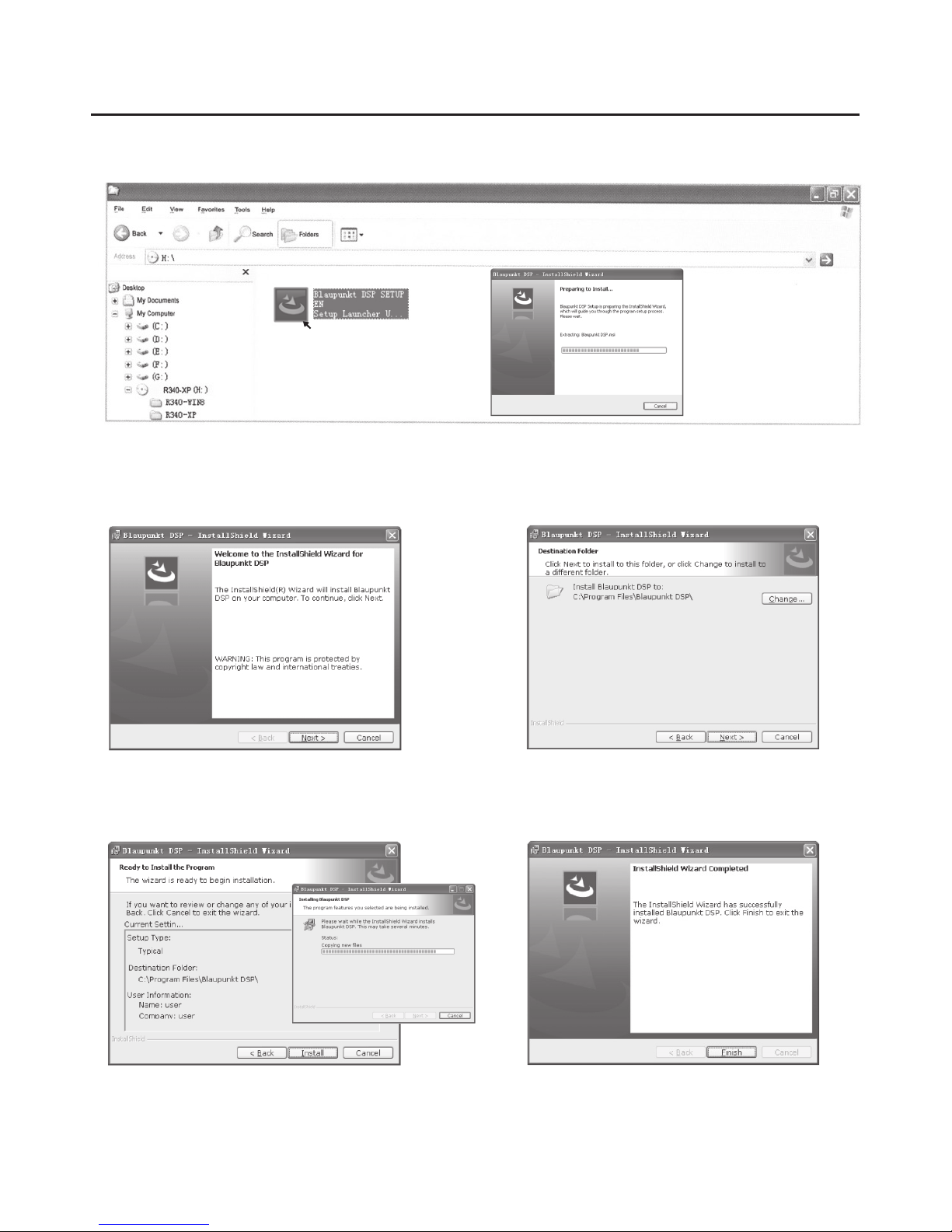
1. Insert Software CD into the PC and double-click on Blaupunkt DSP Setup EN to began installinng software.
(Software is also available at www.blaupunkt.com/ase)
2. Click NEXT 3. Click CHANGE to change le saving location if prefer,
then click NEXT
4. Click INSTALL and wait 5. Click FINISH
Page 7
SOFTWARE OPERATION
6
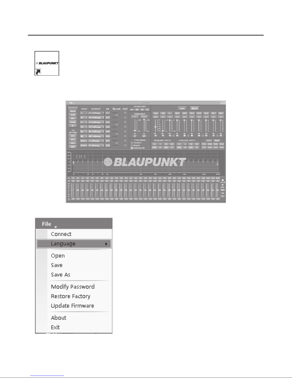
Double-click on Blaupunkt DSP software to began using
Car entertainment enthusiast / experts may now begin to tone signal details. Enhance the sound eect according to
your very own preference for optimum music enjoyment with the DSP software
Blaupunkt DSP 1.0
Click File for Main Menu
1. Connect (connect to the DSP)
2. Language (choose the preferred language)
3. Open (To load preset le in PC folder)
4. Save
5. Save as
6. Change Password
7. Reset (All setting will reset to default setting)
8. Update Firmware
9. About
10. Exit
1. FILE
Page 8

SOFTWARE OPERATION
7
iv. Output Channel
Clik the drop-down button to adjust channel input
Options on the LINK are for combine setting for Left/
Right CH. Tone each selected channel with Left/Right CH
4. CROSSOVER X-TYPE
5. CROSSOVER FREQUENCY
2. INPUT MODE
To select dierent input devices
3. CHANNEL SETTING
i. Optional Fullrange
2-way crossover. 3-way crossover. Clear All
ii. CH Setting (click on the default in put state)
iii. INPUT Channel
Clik the drop-down button to adjust channel input
Page 9

SOFTWARE OPERATION
8
12. READ
i. To read setting from DSP (POS1-POS8)
ii. To delete setting from DSP (POS1-POS8)
13. X-OVER AND EQ CHARTS
i. Red lines and slopes will change when HP/LP of
crossover and EQ are modied.
ii. EQ frequency points can be move left/right. For
20Hz - 20kHz can be any regulation.
14. EQ SETTING
Q value = 1-12
6. GAIN
0-40dB is optional range for gain control kf every CH
7. DELAY
i. Auto conguration (base on 1.5 setting)
ii. Manual congurations in selected CH manually
8. LP/SLOPE
9. HP/SLOPE
10. FILTER MODEL
11. WRITE
H
Page 10

INSTALLATION REFERENCE
9
CHANNEL STAND ALONE TREBLE MODE
2-WAY CROSSOVER TREBLE MODE
3-WAY CROSSOVER TREBLE MODE
CH1/CH2 SPEAKER OUTPUT
CH3/CH4 SPEAKER OUTPUT
CH5/CH6 SPEAKER OUTPUT
CH7/CH8 SPEAKER OUTPUT
MP 68A
Hi Level Input
HU
ACCU
Ground
Subwoofer
FLT W
FRTW
FLMB
FRMB
RLMidrange
RRMidrange
CH1/CH2 SPEAKER OUTPUT
CH3/CH4 SPEAKER OUTPUT
CH5/CH6 SPEAKER OUTPUT
CH7/CH8 SPEAKER OUTPUT
CH1/CH2 SPEAKER OUTPUT
CH3/CH4 SPEAKER OUTPUT
CH5/CH6 SPEAKER OUTPUT
CH7/CH8 SPEAKER OUTPUT
MP 68A
MP 68A
Subwoofer
Hi Level Input
Hi Level Input
HU
HU
ACCU
Ground
Subwoofer / CH7 + CH8
to Subwoofer
FLT W
FRTW
FLMB
FRMB
RLT W
RRTW
RLMB
RRMB
2 CH/
Power
Subwoofer
Subwoofer / CH7 + CH8
to Subwoofer
2 CH/
Power
Ground
Page 11

1.
a. Adjust Volume
b. Press once to MUTE/UNMUTE
c. Press and hold to enter MENU mode
2. Volume display
3. DSP mode display window (1-8)
4. Input display status (CD - AUX - SPDIF - BT)
REMOTE CONTROL KEY FUNCTION
10
Page 12

Designed and engineered by Blaupunkt Competence Center
1 141 18 002 02 01
 Loading...