

Page 1
In Car Video
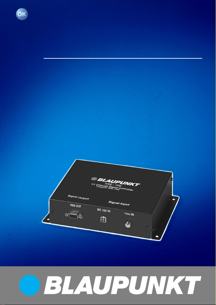
IVSC-1102
Operating and installation instructions
http://www.blaupunkt.com
Page 2

CONTENTS
General information ................. 7
Installation and safety notices .......... 7
Accessories .................................... 7
Function .......................................... 7
Supplied parts .......................... 8
Installation................................ 8
Installation and safety notices .......... 8
Positive connection ......................... 8
Switching positive ........................... 9
Negative (ground) connection .......... 9
Specifications .......................... 9
Features .......................................... 9
Connection diagrams ............. 38
6
Page 3

GENERAL INFORMATION
General information
Thank you for choosing a Blaupunkt
product. We hope you enjoy using this
new piece of equipment.
Please read these operating instructions before using the equipment for
the first time.
The Blaupunkt editors are constantly
working on making the operating instructions clearer and easier to understand. However, if you still have any
questions on how to operate the device,
please contact your dealer or the telephone hotline for your country . You will
find the telephone number printed at the
back of this booklet.
We provide a manufacturer guarantee
for our products bought within the European Union. You can view the guarantee conditions at www.blaupunkt.de
or ask for them directly at:
Blaupunkt GmbH
Hotline
Robert Bosch Str. 200
D-31 139 Hildesheim
Installation and safety notices
Before connecting your signal controller, please read the following information carefully .
The battery’s negative terminal must
be disconnected for the entire time
it takes to install and connect this device.
When doing so, observe the vehicle
manufacturer’s safety notices (airbags,
alarm systems, trip computers, immobilizers).
Before drilling any holes, make sure that
no installed cables or vehicle components can be damaged.
When installing the signal controller,
select a location in the vehicle that allows you to attach it firmly into place
using screws. The installation location
should be such that the signal controller does not get in the way of the driver
and cannot endanger the occupants in
the event of the vehicle suddenly coming to a halt, for instance, during an
emergency stop.
Accessories
We recommend you use accessories
that have been approved by Blaupunkt.
Function
The IVSC-1102 signal controller makes
it possible for you to connect analogue
video sources like the IVDP-01, IVTV01, etc. to Blaupunkt navigation components such as TravelPilot DX-N, DXV and similar devices.
Certain settings must be configured in
the navigation component’s menu before a video source image can be displayed on the navigation monitor.
You will find information on the necessary settings in the operating instructions for those components
.
DEUTSCH
ENGLISH
FRANÇAIS
ITALIANO
NEDERLANDS
SVENSKA
ESPAÑOL
PORTUGUÊS
DANSK
7
Page 4

SUPPLIED PARTS
INSTALLATION
Supplied parts
The signal controller is supplied with all
the parts listed below. Please check that
the range of parts supplied with your
device is complete. If one of the listed
parts is missing, please contact your
dealer immediately .
● Signal controller 7 607 003 553
● Connecting cable
● Screws
● Operating and installation instruc-
tions
Installation
Installation and safety notices
Before connecting your signal controller, please read the following information carefully .
The battery’s negative terminal must
be disconnected for the entire time
it takes to install and connect this device.
When doing so, observe the vehicle
manufacturer’s safety notices (airbags,
alarm systems, trip computers, immobilizers).
Before drilling any holes, make sure that
no installed cables or vehicle components can be damaged.
When installing the signal controller,
select a location in the vehicle that allows you to attach it firmly into place
using screws. The installation location
should be such that the signal controller does not get in the way of the driver
and cannot endanger the occupants in
the event of the vehicle suddenly coming to a halt, for instance, during an
emergency stop.
Note:
Before connecting the monitors to
your signal controller, check that the
+/- and switching positive connections are working properly .
Positive connection
Connect the fuse holder (1A fuse) to
protect the positive cable (permanent
(1), see Fig. 1). The fuse holder should
8
Page 5

INSTALLATION
SPECIFICATIONS
be connected to the positive terminal at
a distance of max. 30 cm from the vehicle battery (if necessary, drill a hole in
the bulkhead and use the appropriate
cable grommets).
Switching positive
Connect the switching positive cable (2)
(see Fig. 1) to the switching positive
output (ignition
) of the main device (e.g. car radio or navigation device).
If connecting to terminal 15 of the vehicle, protect the switching positive cable
(2) by installing a fuse holder (1A fuse)
at a maximum distance of 20 c m from
the point of connection.
Negative (ground) connection
Attach the negative cable (1) (earth/
GND, (3), see Fig. 1) directly to the vehicle body using a screw. Scratch the
surface down to the bare metal at the
point at which the earth contact is made
and apply graphite grease (important for
a good earth connection).
• If the installation requires holes to be
drilled or any other changes to be
made to the vehicle, please contact
a specialist workshop in your area.
Note:
You cannot display PAL video on the
wide vision TV monitor using the RGB
input.
In this case, the P AL video signal must
be connected directly to the AV input of
the wide vision TV monitor.
Specifications
Video input:
Composite Video, 1.0 Vpp, 75 Ohm
RGB output (video signal, internal
resistance 75 ohm):
Typical 0.7 Vpp
RGB output (composite sync, internal resistance 75 ohm):
Typical 1.0 Vpp
Power supply:
DC12V , +/- 10%, max. 1A
Features
1 Video input:
Cinch jack
1 RGB output:
15-pin Sub-D plug-type connector
Conversion:
CCVS (NTSC/PAL) in RGB 50/60 Hz
Power input:
4-pin plug-type connector
Metal housing
DEUTSCH
ENGLISH
FRANÇAIS
ITALIANO
NEDERLANDS
SVENSKA
ESPAÑOL
PORTUGUÊS
DANSK
9
Page 6

Anschlussbilder • Connection diagrams • Schéma
électrique • Schemi di allacciamento • Aansluittekeningen •
Anslutningsbilder • Esquemas de conexión • Esquemas de
ligação • Tilslutningsskemaer
12V
Fig. 1
Video in
Signal Controller
+12V Ignition
Fig. 2
RGB out
(2)
RGB OUT DC 12V IN Video IN
+12V Permanent (Batterie,
battery)
(1)
Masse/GND
(3)
TravelPilot DX...
38
IVSC - 1102
RGB OUT
7 607 001 601 / 1,5 m
7 607 001 602 / 4 m
DC 12V IN
IR
VIDEO IN
Video IN
ON
IVDP-01
IVTV-01
Page 7

Service-Nummern / Service numbers / Numéros du service aprèsvente / Numeri del servizio di assistenza / Servicenummers /
Telefonnummer för service / Números de servicio / Números de
serviço / Servicenumre
Country: Phone: Fax: WWW:
Germany (D) 0180-5000225 05121-49 4002 http://www.blaupunkt.com
Austria (A) 01-610 390 01-610 393 91
Belgium (B) 02-525 5454 02-525 5263
Denmark (DK) 44 898 360 44-898 644
Finland (FIN) 09-435 991 09-435 99236
France (F) 01-4010 7007 01-4010 7320
Great Britain (GB) 01-89583 8880 01-89583 8394
Greece (GR) 210 57 85 350 210 57 69 473
Ireland (IRL) 01-4149400 01-4598830
Italy (I) 02-369 6331 02-369 6464
Luxembourg (L) 40 4078 40 2085
Netherlands (NL) 023-565 6348 023-565 6331
Norway (N) 66-817 000 66-817 157
Portugal (P) 01-2185 00144 01-2185 11111
Spain (E) 902-120234 916-467952
Sweden (S) 08-7501500 08-7501810
Switzerland (CH) 01-8471644 01-8471650
Czech. Rep. (CZ) 02-6130 0441 02-6130 0514
Hungary (H) 01-333 9575 01-324 8756
Poland (PL) 0800-118922 022-8771260
Turkey (TR) 0212-3350677 0212-3460040
USA (USA) 800-2662528 708-6817188
Brasil
(Mercosur) (BR) +55-19 3745 2769 +55-19 3745 2773
Malaysia
(Asia Pacific) (MAL) +604-6382 474 +604-6413 640
Blaupunkt GmbH
07/03 CM/PSS - 8 622 403 776
 Loading...