

Page 1
In Car Video
IVMS-5802
IVMS-6502
Operating and installation instructions
http://www.blaupunkt.com
Page 2
DEVICE OVERVIEW
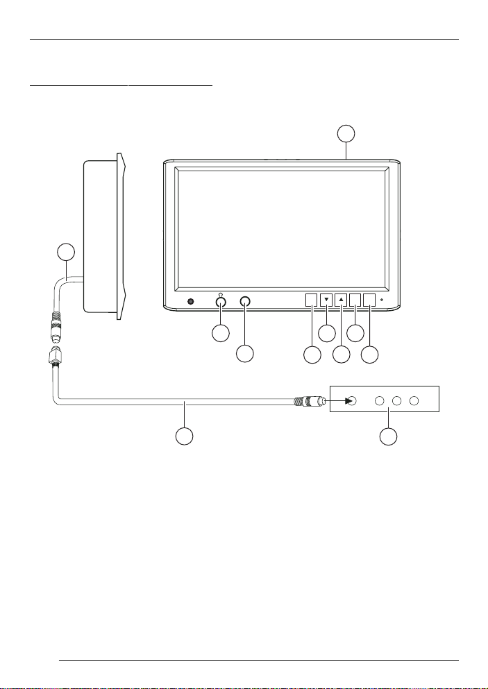
Device overview
5.8" and 6.5" TFT-LCD screen
9
1
VDEO
I
7
8
CH
5
6
ON
MENÜ
3
4
2
10
1 5.8"/ 6.5" TFT LCD screen for
headrests
2 On/off switch
3 Key for screen menu display
(OSD menu)
4 Up menu
5 Down menu
6 AV channel setting
(AV1 - AV2 - ...)
14
11
7 Headphone socket
8 Video input (internal)
9 Connecting cable
: Interface cable
; AV signal converter unit
Page 3

TAB LE OF CONTENTS
Device overview ..................... 14
5.8" and 6.5" TFT-LCD screen ...... 14
General information ............... 16
Important notes ............................. 16
Safety notices ............................... 16
Accessories............................ 17
Accessories supplied .................... 17
Available accessories .................... 17
Fitting ..................................... 17
Monitor installation......................... 17
Prepare the working area .............. 17
Mark out the dimensions ................ 17
Carefully cut open the headrest
cover ............................................. 18
Open the headrest and remove
filling and other items ..................... 18
Lay the cable through the headrest . 19
Insert the mounting frame in the
headrest ........................................ 19
Inserting the monitor ...................... 19
Check and adjust the monitor then
apply the Velcro strips ................... 20
Example of a direct connection to a
DVD player .................................... 20
Positive connection ....................... 20
Negative (ground) connection ........ 21
Removal ................................. 21
OSD menu ............................. 22
Operation ...................................... 22
IR remote control ................... 23
Functions ...................................... 23
Specifications ........................ 24
5.8" screen ................................... 24
6.5" screen ................................... 25
Connection diagram ............ 109
DEUTSCH
ENGLISH
FRANÇAIS
ITALIANO
NEDERLANDS
SVENSKA
15
ESPAÑOL
PORTUGUÊS
DANSK
Page 4
NOTES
General information
Thank you for choosing a Blaupunkt
product. We hope you enjoy using this
new piece of equipment.
Please read these operating instructions before using the equipment for
the first time.
The Blaupunkt editors are constantly
working on making the operating instructions clearer and easier to understand. However, if you still have any
questions on how to operate the device,
please contact your dealer or the telephone hotline for your country . You will
find the telephone number printed at the
back of this booklet.
We provide a manufacturer guarantee
for our products bought within the European Union. You can view the guarantee conditions at www.blaupunkt.de
or ask for them directly at:
Blaupunkt GmbH
Hotline
Robert Bosch Str. 200
D-31 139 Hildesheim
Important notes
This device is not intended for fitting in
the forward section of the passenger
compartment where it could also be
seen by the driver. Fitting this device in
any part of the vehicle where it could
interfere with or distract the driver’s attention is dangerous and is not permitted. The manufacturer cannot accept
responsibility for any damage caused
as a result of improper fitting of this device.
To avoid the risk of electrical
shock, the device must be protected
from water and moisture, and must
not be opened. Dangerously high
voltages are generated inside the
device.
We wish to point out that the right to
claim against warranty is invalidated by
any changes or modifications to the
device that have not been explicitly approved by the manufacturer.
Long-term operation or storage outside
the specific temperature range can lead
to a shortening of the useful life of the
LC display .
Safety notices
Please observe the following safety
notices during installation and whilst
making the connections.
- Disconnect the negative and positive terminals of the battery .
- When doing so, please observe the
safety notices provided by the vehicle
manufacturer.
- Before drilling the holes necessary
for mounting the equipment and for
laying cables, please make sure that
concealed cables, the fuel tank and
fuel lines cannot be damaged in the
process!
16
Page 5
ACCESSORIES FITTING
Accessories
Accessories supplied
- Connecting cable
- Extraction tool
- Operating instructions
- Mounting plate
- Adapter cable for a direct connection
to an AV source
- IR remote control IVRC-06
Available accessories
- Monitor bracket 7608009300
The installation instructions are included
with the bracket.
Note regarding VIDEO IN/AUX:
Only use original Blaupunkt accessory
7 607 001 510.
Or else use a mono plug.
Fitting
Monitor installation
Note:
It is recommended that the fitting is carried out at a specialist workshop.
Prepare the working area
➮ Remove the headrest, and place it
on a working surface that has been
cleared and cleaned, where the further assembly procedures may be
carried out.
Note:
Take appropriate action to ensure that
the headrest is not damaged while fitting the monitor.
DEUTSCH
ENGLISH
FRANÇAIS
ITALIANO
NEDERLANDS
SVENSKA
Mark out the dimensions
➮ Feel the covering of the headrest
carefully to ensure that there are no
invisible parts that would prevent the
monitor from being fitted.
Mark out the surface that needs to be
cut out - its size must match that of the
installation frame.
17
ESPAÑOL
PORTUGUÊS
DANSK
Page 6

FITTING
Carefully cut open the headrest
cover
Use a knife with an adjustable cutting
depth to cut out the planned area.
➮ Make the first cut inside the marked
area at a point about 0.5 cm from one
of the corners, then make a diagonal cut to a point about 0.5 cm from
the opposite corner.
➮ Make a similar cut between the oth-
er two diagonally opposed corners.
Open the headrest and remove
filling and other items
➮ Carefully lift the covering material
away from the cut area.
➮ Adjust the cutting depth of the knife
to about 2.5 cm, and cut into the headrest following a line about 0.5 cm
inside the marked edge.
➮ Carefully lift the filling material at one
corner, and cut deeper into the material with the knife.
➮ Remove the filling material in small
pieces.
➮ As you do this, lift one piece of the
filling material, and ensure that the
cut is being made to an even depth.
To remove other pieces, use a Dremel
saw or another suitable tool.
➮ Insert the monitor to check that it will
fit into the cut area, and make adjustments if necessary .
18
Page 7

Lay the cable through the
headrest
➮ Now pass the supplied cables throu-
gh the opening so that they emerge
from the underneath of the headrest.
➮ If possible, cover the cable with a ca-
ble tunnel.
➮ Now connect the power supply,
ground and video signal cables, to
check that the monitor is working.
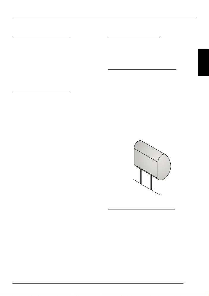
Insert the mounting frame in the
headrest
➮ Before connecting the monitor, pass
the connecting cables through the
holes provided in the mounting plate, as shown in the illustration.
➮ Insert the mounting plate into the
area that has been cut out, and fix it
in place with appropriate fastenings.
FITTING
Inserting the monitor
➮ Before connecting the monitor, pass
the connecting cables through the
holes provided in the mounting plate, as shown in the illustration.
➮ Insert the monitor into the mounting
plate, and attach it with appropriate
fastenings.
Monitor
Mounting plate
DEUTSCH
ENGLISH
FRANÇAIS
ITALIANO
NEDERLANDS
SVENSKA
ESPAÑOL
19
PORTUGUÊS
DANSK
Page 8

FITTING
Check and adjust the monitor
then apply the Velcro strips
➮ Connect the monitor, place it tempo-
rarily in the cut-out, and place the
headrest into position.
➮ Check the various monitor settings
such as brightness, headphone function, volume control and so on.
➮ Then attach the Velcro strips to the
rear of the monitor, and push the frame onto the headrest.
Take care not to press the screen itself, and apply pressure only in the
region of the frame.
Example of a direct connection to
a DVD player
Adapter cable for a
direct connection to an
AV source
DVD - Player (IVDP-01)
Digital
AV
out
in
IVMS 5802/6502
Video out
Audio L out
Audio R out
○○○○○○○○○○○○○
Masse
/GND
+12V
Positive connection
Connect the fuse holder to protect the
positive cable (+12 V). The fuse holder
should be connected to the positive terminal at a distance of max. 30 cm from
the vehicle battery (if necessary, drill a
hole in the bulkhead and use the appropriate cable grommets).
20
Page 9

FITTING
REMOVAL
Negative (ground) connection
Attach the negative cable (earth/GND)
directly to the vehicle body using a
screw. Scratch the surface down to the
bare metal at the point at which the
ground is made.
• If the installation requires holes to be
drilled or any other changes to be
made to the vehicle, please contact
a specialist workshop in your area.
Removal
➮ To remove the screen, insert the ex-
traction tool between the screen and
the mounting plate.
➮ Insert the extraction tool at the place
where a slot has been provided between the screen and the mounting
plate.
Extraction tool
DEUTSCH
ENGLISH
FRANÇAIS
ITALIANO
NEDERLANDS
SVENSKA
21
ESPAÑOL
PORTUGUÊS
DANSK
Page 10

OSD MENU
OSD menu
Operation
➮ Press the “MENU” button on the dis-
play or on the remote control to open
the OSD menu.
●
Use the arrow buttons / to select the options and after you press
the MENU button you can use the
arrow buttons
settings.
➮ Press the “EXIT” option to close the
OSD menu again.
ZOOM
BRIGHTNESS
CONTRAST
COLOR
TINT
REVOLVE LEFT-RIGHT
RESET PICTURE
EXIT
/ to change the
UP-DOWN
●
TINT:
To adjust the picture shade (only
for NTSC)
●
REVOLVE:
To revolve the screen display
- LEFT - RIGHT
Horizontally mirrored
- UP - DOWN
Vertically mirrored
●
RESET PICTURE:
To reset the configured parameters
to the factory default settings.
●
EXIT:
To close the OSD menu
●
ZOOM (picture size):
Change the picture height/width
- FULL
- NORMAL
- WIDE
●
BRIGHTNESS
To adjust the brightness
●
CONTRAST:
To adjust the contrast
●
COLOR:
To adjust the colour
22
Page 11

IR remote control
Functions
The supplied remote control is suitable
for operating the following monitors:
IVMS-5802 and IVMS-6502.
1 POWER
On/off button for the monitor.
2 TV/VIDEO
No function.
/
/
buttons
3 VOL • arrow button
Increase the volume for the selected monitor.
VOL • arrow button
Decrease the volume for the selected monitor.
4 MUTE
Mute the volume of the loudspeakers inside the monitor.
5 CH • arrow button
Channel selection if the monitor is
connected to a signal controller
IVSC-3302 or IVSC-5502.
Caution:
The way the CH
function depends on the monitor
selection (which is made using
the signal controller’s remote control).
6 Menu
See OSD menu, operation (page
22).
IR REMOTE CONTROL
1
2
MENÜ
IVRC-06
3
MUTETV/VIDEOPOWER
VOL CH
4
5
6
DEUTSCH
ENGLISH
FRANÇAIS
ITALIANO
NEDERLANDS
SVENSKA
ESPAÑOL
PORTUGUÊS
23
DANSK
Page 12

SPECIFICATIONS
Specifications
5.8" screen
System: NTSC/P AL auto switch
Power supply / consumption: 12 V direct current, ± 10%,
<900 mA
Standby: < 1 mA
Video input level: 1 Vpp, 75 ohms
Audio input level: 0 - 0.3 Vrms, 20 Hz - 20 kHz
Operating temperature: -20° C to +60° C
Storage temperature: -30° C to +80° C
Screen size (diagonal): 5.8" (14.7 cm)
Contrast ratio: 60
Power consumption: < 11 W
Brightness: 300 cd/m
Display technology: TFT active matrix system
Resolution (pixels): 1200 (H) x 234 (W) = 280,800 pixels
Visible screen area: 127.20 (W) x 71.84 (H) mm
Viewing angle: From the left and right: 60°,
From above: 60°,
From below: 30°
Total monitor dimensions: 165 (W) x 122 (H) x 26.7 (D) mm
Monitor weight: < 400 g
2
24
Page 13

6.5" screen
SPECIFICATIONS
System: NTSC/PAL auto switch
Power supply / consumption: 12 V direct current, ± 10%,
<900 mA
Standby: < 1 mA
Video input level: 1 Vpp, 75 ohms
Audio input level: 0 - 0.3 Vrms, 20 Hz - 20 kHz
Operating temperature: -20° C to +60° C
Storage temperature: -30° C to +80° C
Screen size (diagonal): 6.5" (16.5 cm)
Contrast ratio: 60
Power consumption: < 10 W
Brightness: 280 cd/m
2
Display technology: TFT active matrix system
Resolution (pixels): 1200 (H) x 234 (W) = 280,800 pixels
Visible screen area: 142.80 (W) x 87.70 (H) mm
Viewing angle: From the left and right: 60°,
From above: 60°,
From below: 30°
Total monitor dimensions: 176.0 (W) x 122 (H) x 26.7 (D) mm
Monitor weight: < 400 g
DEUTSCH
ENGLISH
FRANÇAIS
ITALIANO
NEDERLANDS
SVENSKA
ESPAÑOL
Subject to changes!
PORTUGUÊS
DANSK
25
Page 14
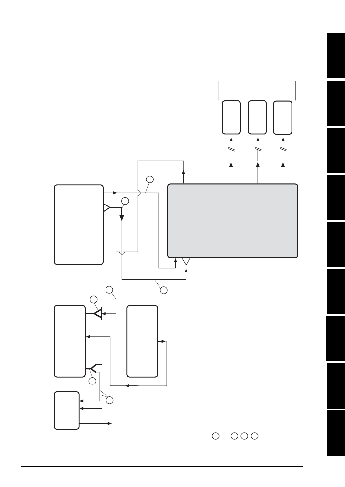
Anschlussbild • Connection diagram • Schéma de connexion
Speakers
Video 1
Audio L 1
Audio R 1
Video 2
Audio L 2
Audio R 2
Video 3
Audio L 3
Audio R 3
Signal Controller IVSC-3302
Preamp
out
Car Radio
2x Aux-in
Amplifier
Anschlusskabel/Additional Cables:
1
RCA-Cable 7 607 885 093 (1,3m)
7 607 886 093 (5m)
2
RCA-Y-Cable 7 607 001 507
3
C1-4x Cinch 7 607 893 093 (0,35m)
4
AUX 2-in 7 607 001 508
1
1
in
4
3
1
AUX 2
CDC
in
Audio
out
D 3
D 2
D 1
DVD - Player (IVDP-01)
Video out
AV
in
Digital
out
Audio L out
Audio R out
CDC-A08
IDC-A09
CDC
out
2
1
Right
Monitor
Left
Monitor
IVMS 5802/6502
Front
Monitor
• Schema di allacciamento • Bedradingsschema •
Anslutningsschema • Cuadro de conexiones • Esquema de
ligação • Tilslutningsbillede
DEUTSCH
Connection example with various components
Beispielanschluss mit verschiedenen Komponenten /
ENGLISH
FRANÇAIS
ITALIANO
NEDERLANDS
SVENSKA
ESPAÑOL
PORTUGUÊS
DANSK
109
Page 15

Service-Nummern / Service numbers / Numéros du service aprèsvente / Numeri del servizio di assistenza / Servicenummers /
Telefonnummer för service / Números de servicio / Número de
serviço / Servicenumre
Country: Phone: Fax: WWW:
Germany (D) 0180-5000225 05121-49 4002 http://www.blaupunkt.com
Austria (A) 01-610 390 01-610 393 91
Belgium (B) 02-525 5454 02-525 5263
Denmark (DK) 44 898 360 44-898 644
Finland (FIN) 09-435 991 09-435 99236
France (F) 01-4010 7007 01-4010 7320
Great Britain (GB) 01-89583 8880 01-89583 8394
Greece (GR) 210 57 85 350 210 57 69 473
Ireland (IRL) 01-4149400 01-4598830
Italy (I) 02-369 6331 02-369 6464
Luxembourg (L) 40 4078 40 2085
Netherlands (NL) 023-565 6348 023-565 6331
Norway (N) 66-817 000 66-817 157
Portugal (P) 01-2185 00144 01-2185 11111
Spain (E) 902-120234 916-467952
Sweden (S) 08-7501500 08-7501810
Switzerland (CH) 01-8471644 01-8471650
Czech. Rep. (CZ) 02-6130 0441 02-6130 0514
Hungary (H) 01-333 9575 01-324 8756
Poland (PL) 0800-118922 022-8771260
Turkey (TR) 0212-3350677 0212-3460040
USA (USA) 800-2662528 708-6817188
Brasil
(Mercosur) (BR) +55-19 3745 2769 +55-19 3745 2773
Malaysia
(Asia Pacific) (MAL) +604-6382 474 +604-6413 640
Blaupunkt GmbH
07/03 CM/PSS2 - 8 622 403 803
 Loading...