

Page 1
In Car Video
IVMR-7001
Operating and installation instructions
http://www.blaupunkt.com
Page 2
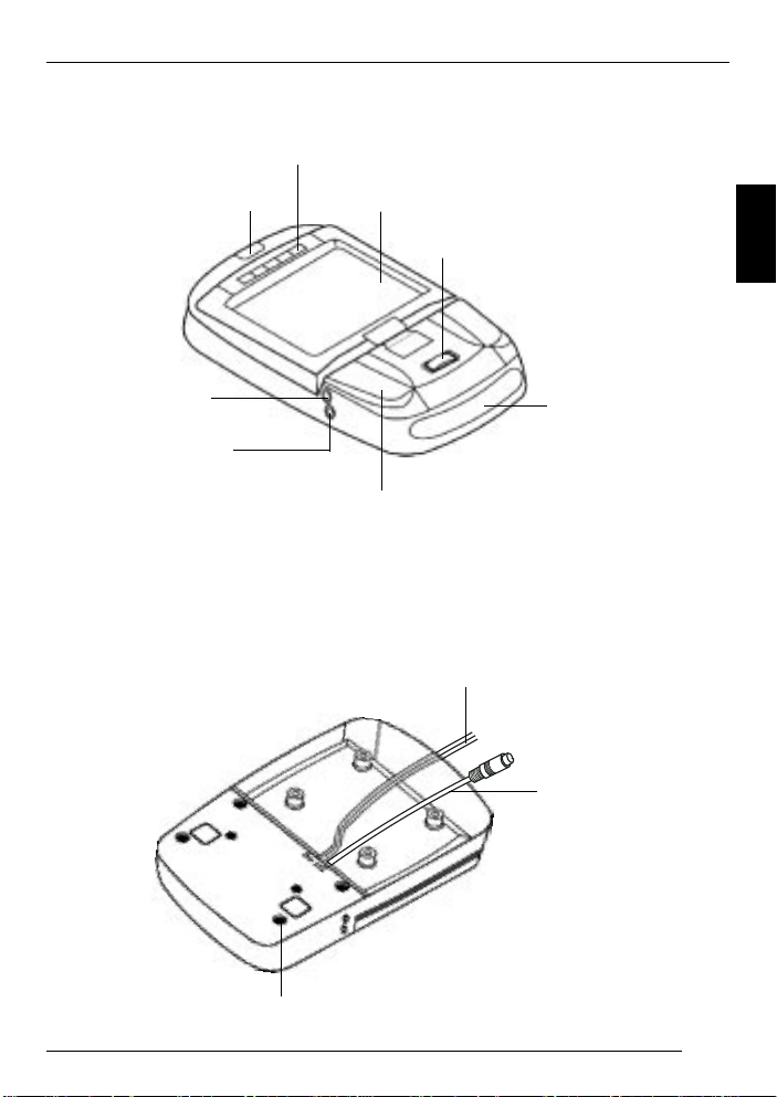
Front view
DEVICE OVERVIEW
Monitor release button
AUX socket
Headphones socket
Rear view
Control buttons
LCD screen
Light switch
Main light unit
Light cable for the main unit
DEUTSCH
ENGLISH
FRANÇAIS
Infrared receiver
ITALIANO
NEDERLANDS
SVENSKAESPAÑOL
Connecting cable
Screws
PORTUGUÊS
DANSK
17
Page 3

CONTENTS
Notes for the user .................. 19
Supplied equipment .............. 20
Using for the first time ........... 21
Using the interior light .................... 21
Changing the light bulb ................. 22
Light bulb specifications ................ 22
Wiring ........................................... 22
Monitor connection ........................ 22
Installing the monitor...................... 23
Operation ............................... 24
Opening the monitor ...................... 24
Repositioning the monitor .............. 24
Closing the monitor ....................... 24
Switching on the monitor ............... 24
Display controls ............................. 25
Remote control .............................. 25
OSD menu .................................... 26
IR-Headphones ...................... 28
Specifications ........................ 30
Guarantee .............................. 31
Appendix ................................ 31
Changing the battery in the
remote control ............................... 31
18
Page 4

NOTES FOR THE USER
Notes for the user
Please observe all the warning notices,
precautionary measures and maintenance tips contained in these operating instructions so as to extend the life
of your monitor.
● To avoid causing a road accident,
never use the monitor during the
journey.
● Do not place the monitor’s aerial in
the following positions:
1. Positions in which the driver’s
view could be restricted.
2. Positions in which the aerial
could become a danger to safety (e.g. handbrake, steering
wheel, gearshift lever and airbag).
● To avoid the danger of receiving an
electric shock and damaged to the
monitor, make sure that the monitor cannot become wet or moist. If,
however, this does occur, switch
the device off, disconnect the electrical cable, and take the monitor to
your local specialised dealer as
quickly as possible or send it in to
our customer service centre.
● Only operate the device with the
recommended electrical supply of
12V direct current.
● Make sure you do not place or
hang any objects on the electrical
cable since this could damage it.
● Avoid laying the cable haphazardly
or twisting it. Keep it away from
heated objects.
● Do not attempt to repair the electri-
cal cable if it becomes damaged or
severed – instead, replace it immediately with a new one.
● Make sure that no metallic or in-
flammable objects make their way
into the monitor’s insides through
the ventilation slots.
● Do not attempt to open or disman-
tle the monitor, since you could suffer an electric shock as a result.
● If you detect smoke or a strange
smell, disconnect the electrical cable immediately and take it to your
local specialised dealer or send it
in to our customer service centre.
● If the monitor’s housing is dam-
aged or broken, take it to your local
specialised dealer or send it in to
our customer service centre.
● Avoid using the monitor in places
where it is subjected to dust, dirt or
moisture.
● Do not install the monitor in places
where it is subjected to direct sunlight or extreme temperatures.
● Do not subject the monitor to the
wet or moisture.
● After installing the monitor, avoid
knocking it or pulling it downwards
excessively , since this will loosen
the screws and the monitor could
drop off.
DEUTSCH
ENGLISH
FRANÇAIS
ITALIANO
NEDERLANDS
SVENSKAESPAÑOL
PORTUGUÊS
DANSK
19
Page 5

SUPPLIED EQUIPMENT
Supplied equipment
The monitor is supplied with all parts listed below. Please check that your device is supplied with all the parts. If one
of the listed parts is missing, please contact your dealer immediately .
Standard package
● Monitor (including mounting fixture)
● Remote control with battery
● IR-Headphones
● 500 cm long, 8-pin system cable
(only for AV signal converter)
● Operating instructions
20
Page 6
USING FOR THE FIRST TIME
Using for the first time
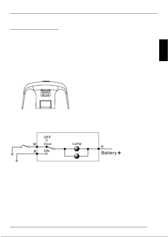
Using the interior light
There are three settings for the interior
light: OFF , DOOR and ON (see diagram
below).
OFF: The lights are switched off.
DOOR: With this setting, the lights only
come on when the vehicle’s doors are
opened.
ON: The lights are switched on.
OFF DOOR ON
Circuit diagram
Notes:
● There is no electrical cable con-
nected to position “B”, since “B” is
connected to the ground via two
screws.
● The power supply must be
12 volts.
DEUTSCH
ENGLISH
FRANÇAIS
ITALIANO
NEDERLANDS
SVENSKAESPAÑOL
W = White = Connection to the sensor
B = Black = Ground
R = Red = Electrical connection
PORTUGUÊS
DANSK
21
Page 7

USING FOR THE FIRST TIME
Changing the light bulb
To fit a new bulb, proceed as follows:
➮ Set the light switch to “OFF”.
➮ Push back the bulb cover and open
it (see diagram below).
➮ Remove the old bulb and dispose
of it.
➮ Fit a new bulb.
➮ Close the bulb cover.
Bulb cover
Light bulb
Light bulb specifications
Diameter: 8 mm
Length: 29 mm
Voltage: 12 V direct current,
5 W
Type: Stanley A3022C or a
type with the same
specifications
Wiring
Bulb for the main unit
Light cable for the main unit
Connecting
cable
Screws
Red = Electrical supply (12 V)
White = Internal lighting system
Black = Ground
Caution:
● The screws have different sizes.
Make sure that you insert the
screws in the correct positions.
● Make sure that the screws are
screwed tight to ensure a good
ground connection.
Monitor connection
Connecting cable
System cable
Light cable for the main unit
22
Page 8

USING FOR THE FIRST TIME
Installing the monitor
Select a suitable position for secure installation of the monitor:
● The device must not distract the
driver or restrict the driver’s view.
● The ability to enter and get out of
the vehicle must not be impeded.
● The device must not be installed in
such a way that could prevent the
other vehicle components from
functioning properly (e.g. sliding
sunroof).
● Make sure that the device is in-
stalled in a safe and secure position and cannot become detached
in the event of an emergency stop.
● Do not attach the device merely to
the roof liner.
● If you need to drill additional holes,
make sure you do not drill through
the vehicle’s sheet metal.
● Avoid using the monitor over a
longer period of time whilst the engine is off so as to prevent the battery from becoming drained.
DEUTSCH
ENGLISH
FRANÇAIS
ITALIANO
NEDERLANDS
SVENSKAESPAÑOL
23
PORTUGUÊS
DANSK
Page 9

OPERATION
Operation
Opening the monitor
➮ Press the monitor release button to
flip down the LCD display.
➮ To watch the television, lower the
monitor until it is at an angle of 90
degrees to the main unit.
Repositioning the monitor
The monitor can be rotated by up to 30
degrees to the right and left from its
central viewing position (see the following diagram).
Closing the monitor
➮ Rotate the monitor back to its cen-
tral viewing position (see the following diagram).
➮ Push the monitor back into its main
unit so that the screen clips back
into the releasing/locking mechanism.
Switching on the monitor
Press the power-on button on the main
unit or on the remote control to switch
the monitor on/off.
Note:
Before the monitor is switched on, the
power indicator lights up orange. This
means that the monitor is connected to
the 12 V direct current electrical supply .
Furthermore, “NO SIGNAL” will flash on
and off in the on-screen display (OSD)
as long as there is no A/V input signal
present.
24
Page 10

OPERATION
Display controls
SRC
● POWER:
This button is used to switch the main
unit on/off.
● OSD:
OSD
ON
➮ Press the “OSD” button to open the
OSD menu or select a function in
the OSD menu.
● SRC:
➮ Press this button to select the AV
channel (channel 1 – channel 5) of
the AV signal converter.
:You can use this button to in-
crease the volume.
You can also navigate upwards
in the OSD menu using this
button.
:You can use this button to de-
crease the volume.
Press this button to navigate
downwards in the OSD menu.
Remote control
MUTE
AV/T V
MENU
CHANNEL
● POWER:
POWER
AUTO PROG
VOLUME
To switch the main unit on/off
● MUTE (Stumm):
Turns down the volume to zero
● AV/TV:
➮ Press this button to switch between
AV and TV channels.
Note:
This function is only available if the E/A
box is connected or the E/A box together with the tuner box.
● AUTO PROG (Automatic program-
ming):
Select this option on the remote control
or in the OSD menu if you want the
monitor to automatically search and
store the television channels.
The specifications are as follows:
TV system Channels
USA 2-69
JAPAN 1-62
PALB/G 2-69
PALD/K 1-57
PALA/I 21-69
DEUTSCH
ENGLISH
FRANÇAIS
ITALIANO
NEDERLANDS
SVENSKAESPAÑOL
PORTUGUÊS
DANSK
25
Page 11

OPERATION
Note:
This function is only available if the E/A
box is connected together with the tuner box.
● MENU:
You can use this button to open the OSD
menu.
● CHANNEL:
These buttons allow you to select the
selected channels or functions in the
OSD menu.
● VOLUME:
1. To adjust the volume
2. To adjust settings in the OSD menu
OSD menu
Main menu
➮ Press the “SRC” button on the
main unit or “MENU” on the remote
control to open the main menu.
Use “EXIT” to close the OSD menu
again.
VOLUME
BRIGHTNESS
CONTRAST
COLOR
TINT
MISC
EXIT
+
● VOLUME:
To adjust the volume
● BRIGHTNESS:
To adjust the brightness
● CONTRAST:
To adjust the contrast
● COLOR:
To adjust the colour
● TINT:
To adjust the tint
● MISC:
To open the submenu
● EXIT:
To close the OSD menu
Submenu
➮ In the main menu, select the
“MISC” option to display the following choice of options.
➮ Select “MAIN MENU” to return to
the main menu and then “EXIT” to
close the OSD menu.
ZOOM: FULL
SPEAKER: OFF
REVOLVE: LEFT RIGHT
REVOLVE: UP DOWN
RESET PICTURE
MAIN MENU
26
Page 12

OPERATION
● FM CHAN:
Use this option to select the FM channel. This channel is set by default to
“OFF”.
The specifications are as follows:
TV system FM frequency (MHz) in
steps of 0.2 MHz
USA OFF / 88.1 - 91.9
JAPAN OFF / 77.1 - 80.9
PALB/G OFF / 88.1 - 91.9
PALD/K OFF / 88.1 - 91.9
PALA/I OFF / 88.1 - 91.9
● AUTO PROG (Automatic program-
ming):
Please refer to the “AUTO PROG” function in the section describing the remote
control.
● AV OUT:
Select this option to switch between the
AV output modes “Constant” and “Variable”.
● ZOOM :
This mode is set by default to “Full”. Y ou
can use the
and buttons to switch
between the following settings:
Full = for displaying a 4:3 signal on a
16:9 screen format
ZOOM1 = Picture height expansion,
zoom factor = 4/3
WIDTH1 = Picture height expansion and
different picture width change
Normal = Side ratio of 4:3
ZOOM2 = Zoom factor = 8/7, picture
height expansion
WIDTH = Different picture width change
WIDTH2 = Picture height expansion and
different picture width change
ZOOM3 = vertical expansion, zoom fac-
tor = 8/7
● SPEAKER:
Select the “SPEAKER” option and then
use the
and buttons to switch the
monitor loudspeaker on/off.
● REVOLVE:
This function and the and buttons
allow you to reverse the picture (i.e.
right-to-left reversed).
● RESET PICTURE:
Select the “RESET PICTURE” option to
reset the adjusted parameters back to
their factory defaults.
● MAIN MENU:
If you are in the submenu, you can return to the main menu by selecting this
option.
● AUX (input):
Video input for connecting an additional signal source (games console, camcorder, etc.)
Note:
Only use original Blaupunkt
accessory 7 607 001 510.
Or else use a mono plug.
DEUTSCH
ENGLISH
FRANÇAIS
ITALIANO
NEDERLANDS
SVENSKAESPAÑOL
PORTUGUÊS
DANSK
27
Page 13

IR-HEADPHONES
1. Infrared sensors
2. On/off switch
3. Stereo / mono
4. Volume control
Operating instructions
1. Switch on the audio/video device
that is connected to the transmitter.
2. Move the on/off switch on the
headphones to the on position.
OFF / ON
5. Battery compartment cover
6. Ear cushion
7. Adjustable headband
3. Adjust your preferred volume using the volume control on the left
whilst making sure you do not obstruct the sensors.
28
Page 14

IR-HEADPHONES
4. For stereo audio, move the switch
to the stereo position. Move the
switch to the mono position for
mono audio/video devices.
Specifications
Surround transmitter:
Power consumption
Effective angle
Weight
Stereo headphones:
Type
Transducer system
Impedance
Frequency response
Sound intensity level
Distortion
Infrared wavelength
Modulation
Carrier frequency
Power supply
Battery operating time
(at 10 mV output power)
Weight
Range
5. Reception position
The headphones/receiver receive
audio signals within certain ranges
from any direction and directly .
You will enjoy the best reception
if you stay within a distance of
5 metres from the transmitter.
12 V DC 200 mA
120 degrees
approx. 55 g
dynamic, open
40 mm Mylar membrane
32 ohm +/- 6.4 ohm
20 Hz – 23 KHz
98 dB/rated deviation
1 % total harmonic distortion
at rated deviation
845 mm +/- 5 mm
high frequency modulation
right 2.8 MHz, left 2.3 MHz
2 DCV (1.5 V AAA x 2)
approx. 48 hours
approx. 170 g (without batteries)
approx. 7 metres
DEUTSCH
ENGLISH
FRANÇAIS
ITALIANO
NEDERLANDS
SVENSKAESPAÑOL
PORTUGUÊS
DANSK
29
Page 15

SPECIFICATIONS
Specifications
Screen size: 7" Monitor, A1
Screen resolution:
1440 (H) x 234 (V)
Active area: 154.08 (H) x
86.58 (V)
Pixel pitch (mm): 0.107 (H) x
0.370 (V)
Signal system: Dual system NTSC/
PAL
Brightness: 400 cd/m
Contrast ratio: 150
Viewing angle:
Left/right: 60/60 degrees
Top/bottom: 60/30 degrees
Response time (rise/fall):
25/30 ms
Video input level: 1.0 Vpp ± 10%
2
Carrier frequency for IR sensor:
L-CH : 2.3 MHz
R-CH : 2.78 MHz
Headphones output level:
1.0 Vpp
Operating voltage (direct current
voltage): 1 1 - 15 V
Power consumption:
9 W
Operating temperature:
0 - 60° C
Storage temperature:
-25 - 80° C
Dimensions: 320 x 195 x
60 mm
Weight: 1,200 ± 50 g
Audio input level: 0.3 Vrms
A/V input level: 1.0 Vpp ± 10%
AUX input level: 1.0 Vpp ± 10%
30
Page 16

GUARANTEE
APPENDIX
Guarantee
The scope of the guarantee depends
on the regulations in force within the
country in which the unit was purchased.
We provide a manufacturer guarantee
for our products bought within the European Union. You can view the guarantee conditions at www.blaupunkt.de
or ask for them directly at:
Blaupunkt GmbH, Hotline CM/PSS 6,
Robert Bosch Str. 200,
D-31 139 Hildesheim, Germany
This guarantee does not cover damage
due to wear, incorrect usage or commercial use.
If you wish to enforce a claim under the
manufacturer’s guarantee that is provided by Blaupunkt, please send the faulty
equipment together with the purchase
receipt to the Blaupunkt customer service centre in your country . You can find
out which address is closest to you by
contacting the telephone hotline listed
on the back page of this booklet. Blaupunkt retains the right to rectify defects
or supply a replacement.
Appendix
Changing the battery in the
remote control
➮ Push the battery compartment but-
ton to the right (see A below).
➮ Pull the battery compartment out of
the remote control (see B below).
➮ Change the battery .
+
A
B
DEUTSCH
ENGLISH
FRANÇAIS
ITALIANO
NEDERLANDS
SVENSKAESPAÑOL
Subject to changes!
PORTUGUÊS
DANSK
31
Page 17

Service-Nummern / Service numbers / Numéros du service aprèsvente / Numeri del servizio di assistenza / Servicenummers /
Telefonnummer för service / Números de servicio / Números de
serviço / Servicenumre
Country: Phone: Fax: WWW:
Germany (D) 0180-5000225 05121-49 4002 http://www.blaupunkt.com
Austria (A) 01-610 390 01-610 393 91
Belgium (B) 02-525 5454 02-525 5263
Denmark (DK) 44 898 360 44-898 644
Finland (FIN) 09-435 991 09-435 99236
France (F) 01-4010 7007 01-4010 7320
Great Britain (GB) 01-89583 8880 01-89583 8394
Greece (GR) 0800-550 6550 01-576 9473
Ireland (IRL) 01-4149400 01-4598830
Italy (I) 02-369 6331 02-369 6464
Luxembourg (L) 40 4078 40 2085
Netherland (NL) 023-565 6348 023-565 6331
Norway (N) 66-817 000 66-817 157
Portugal (P) 01-2185 00144 01-2185 11111
Spain (E) 902-120234 916-467952
Sweden (S) 08-7501500 08-7501810
Switzerland (CH) 01-8471644 01-8471650
Czech. Rep.(CZ) 02-6130 0441 02-6130 0514
Hungary (H) 01-333 9575 01-324 8756
Poland (PL) 0800-118922 022-8771260
Turkey (TR) 0212-3350677 0212-3460040
USA (USA) 800-2662528 708-6817188
Brasil
(Mercosur) (BR) +55-19 3745 2769 +55-19 3745 2773
Malaysia
(Asia Pacific) (MAL) +604-6382 474 +604-6413 640
Blaupunkt GmbH
08/02 CM/PSS2 - 8 622 403 175 B
 Loading...