

Page 1
Installation and Operation Manual
Teranex Mini
IP Video 12G
April 2017
Page 2

Welcome
Thank you for purchasing Teranex Mini IP Video 12G, a Teranex Mini converter that lets you
send SDI video over IP networks.
English
Your Teranex Mini IP Video 12G converts SDI video into TICO encoded data which can be
delivered over your network via Ethernet. A second unit connected to the network decodes the
data and converts it back to SDI so you can plug the video into other SDI equipment.
With multiple units connected to your network as sources or destinations, you can route any
signal to any unit using Blackmagic Videohub Control or Teranex setup software, or via the LCD
menu with an optional Teranex Mini Smart Panel attached.
HD video can be connected via the 1G Ethernet port, or you can install an optional 10G Ethernet
optical fiber SFP module if you want to connect Ultra HD video!
This instruction manual contains all the information you need to start using your Teranex Mini
IPVideo 12G.
Please check the support page on our website at www.blackmagicdesign.com for the latest
version of this manual and for updates to your IP Video 12G converter’s software. Keeping your
software up to date will ensure you get all the latest features as well as support for any new
SDIformats that might be invented in the future! When downloading software, please register
with your information so we can keep you updated when new software is released or you can
follow us on twitter to get notifications of any software updates. We are continually working on
new features and improvements, so we would love to hear from you!
Grant Petty
CEO Blackmagic Design
Page 3

Contents
Teranex Mini IP Video 12G
Getting Started with HD 4
Connecting Power 4
Connecting HD Video 4
Connecting Audio 6
Connecting to your Network 6
Network Settings 6
Setting a Unit as a Source or Destination 6
Routing Sources and Destinations 7
Low Latency and Clean Switching 8
Adding More Units to the Network 8
Getting Started with Ultra HD 9
Connecting Power 9
Connecting Ultra HD Video 9
Connecting Audio 11
Connecting to your Network 11
Network Settings 11
Setting a Unit as a Source or Destination 11
Routing Sources and Destinations 12
Low Latency and Clean Switching 13
Adding More Units to the Network 13
Settings 14
Installing Blackmagic Teranex Setup 14
Changing Settings using a
Teranex Mini Smart Panel 18
Smart Panel Settings 20
Changing Settings using Switches 21
Teranex Mini Rack Shelf 22
Setting up and Routing an IP
Videohub 23
Installing Blackmagic
Videohub Software 23
Creating an IP Videohub 24
Removing an IP Videohub 26
Blackmagic Videohub Control 26
Blackmagic Videohub Control
at a Glance 29
Using a Videohub Hardware Panel 32
Teranex Mini IP Video 12G Block
Diagram 33
Updating the Internal Software 34
Appendix 35
Help 36
Regulatory Notices and Safety
Information 37
Warranty 38
Page 4

Getting Started with HD
1G
ETHERNET PoE+
10G
ETHERNET
SDI IN
SDI OUT
SDI OUT
For a basic IP video connection, you will need two Teranex Mini IP Video 12G’s. One unit will be
the source, which will convert your source video using TICO encoding, and the other unit will be
the destination, which receives the TICO encoded video signal and converts it back to SDI so
you can then plug it into other SDI equipment such as a monitor or recording deck.
TICO encoding is a visually lossless compression specifically designed to let you to distribute
high quality video across an IP network.
However, Teranex Mini IP Video 12G is more than a simple point to point video over Ethernet
converter, because it can also use the Blackmagic Videohub Software. This turns any Windows
or Mac OS computer into a router server that can manage the connections between many units
so you can build a large custom sized router, all using your network.
The advantage of this is you can customize the size of your router plus you can also use
broadcast router control panels, routing software and even custom automation solutions
designed for Blackmagic Design’s Videohub routers. This eliminates the user and installation
complexity, and the whole system is as fast to use as any traditional broadcast style router.
Connecting Power
The first step is to plug in power to your Teranex IP Video 12G units. To supply power, simply
plug a standard IEC power cable into the power input on each unit’s rear panel. When power is
connected, the small LED indicator on the basic front panel illuminates white.
NOTE You can also power your IP Video 12G via Ethernet by connecting the 1G Ethernet
PoE+ port on the rear of each unit into a compatible Ethernet switch that supports PoE+
or ‘power over Ethernet plus’.
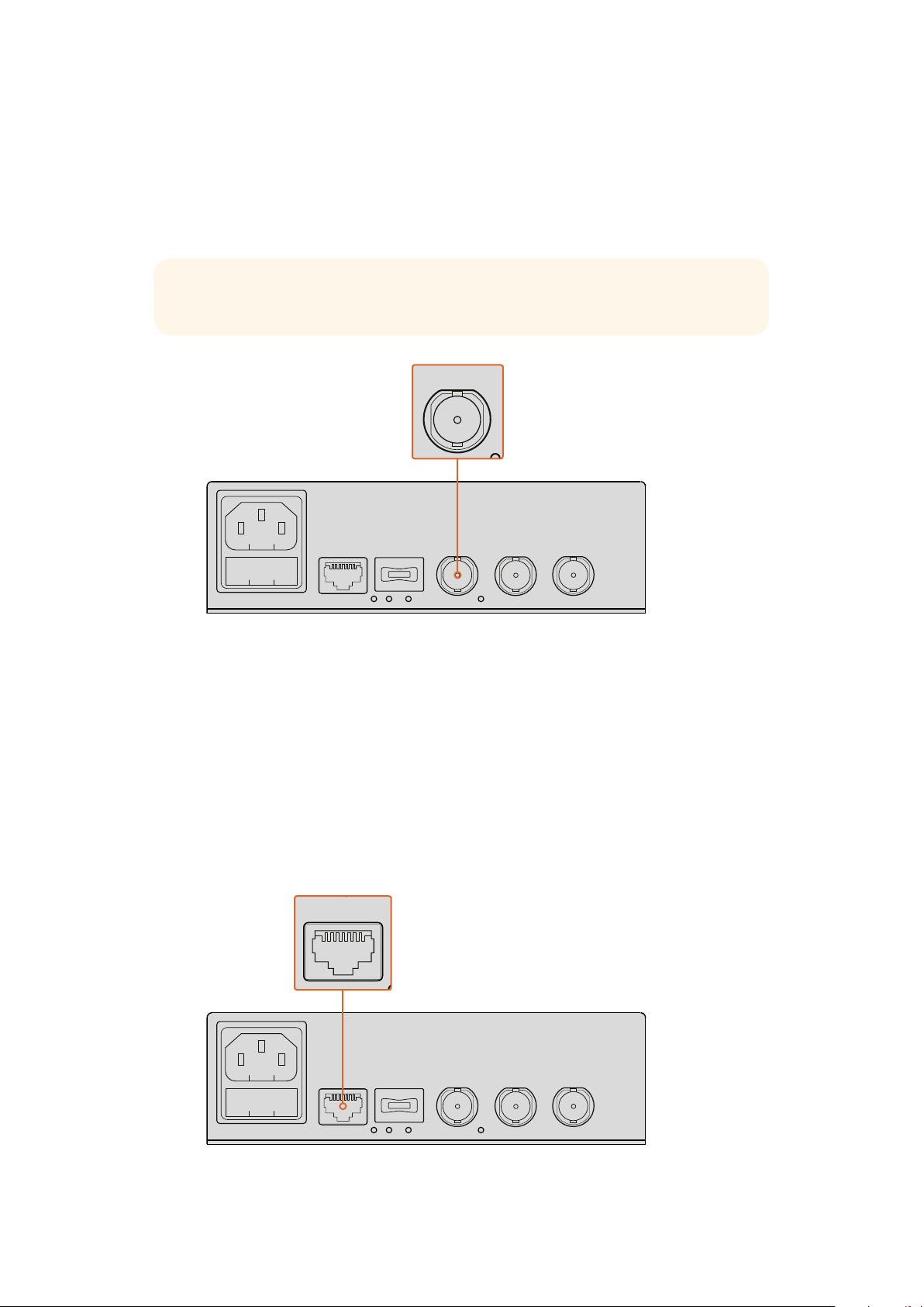
Connec t power to your Blackmagic Teranex Mini IP Video
12G’s rear panel using a standard IEC power cable, or via
1G Ethernet if your network switch suppor t PoE+
Connecting HD Video
ETHERNET PoE+
1G
10G
ETHERNET
SDI IN
SDI OUT
SDI OUT
Teranex Mini IP Video 12G takes an HD video source connected via the unit’s SDI input and
converts the signal using TICO encoding so you can connect the video output to your network
via Ethernet.
44Getting Started with HD
Page 5
Plugging in the HD Source Video
1G
ETHERNET PoE+
10G
ETHERNET
SDI IN
SDI OUT
SDI OUT
SDI IN
SDI OUT
SDI OUT
SDI IN
SDI OUT
SDI OUT
1G
ETHERNET PoE+
10G
ETHERNET
SDI IN
SDI OUT
SDI OUT
1G
ETHERNET PoE+
10G
ETHERNET
SDI IN
SDI OUT
SDI OUT
1G
ETHERNET PoE+
10G
ETHERNET
SDI IN
SDI OUT
SDI OUT
Connect the HD source video to a source unit via the SDI in connector on the rear panel. The
unit will automatically detect the video format and the LED indicator on the basic front panel will
illuminate green. The small LED indicator next to the SDI connector will also illuminate to let you
know the signal is locked.
TIP If you have a Teranex Mini Smart Panel attached, the source video can be seen on
the panel’s LCD.
1G
ETHERNET PoE+
10G
ETHERNET
SDI IN
SDI OUT
SDI OUT
Plug the SDI source video into the source unit’s SDI video input
Plugging in Video via Ethernet
The next step is to connect the unit’s 1G Ethernet output to your network. HD video is sent and
received via the 1G Ethernet connector on the unit’s rear panel. The direction of the signal, for
example a video input or output, depends on whether you have set the unit as a source or
destination. You can find more information about this setting in the ‘setting Teranex Mini IP
Video 12G as a source or destination’ section in this manual.
You can plug into your network using a standard Cat 5 or Cat 5e Ethernet cable, however we
recommend using a shielded cable, such as a Cat 6a S/FTP network cable. A shielded cable
will prevent potential electromagnetic interference when the unit is positioned near other
electrical equipment.
1G
ETHERNET PoE+
10G
ETHERNET
SDI IN
SDI OUT
SDI OUT
Plug HD video to and from your network via the 1G Ethernet connector
55Getting Started with HD
Page 6

Connecting the Destination Video Output
For the destination unit, you will likely want to connect the unit’s video outputs to other SDI
equipment, for example a HyperDeck Disk Recorder or SDI monitor. To do this, simply plug into
the SDI outputs on the unit’s rear panel. There are two SDI outputs so you have the option to
plug into more SDI equipment if you need to.
Connecting Audio
There are no separate audio inputs as audio is always embedded into the SDI video signal and
is carried across the network in sync with the video.
Connecting to your Network
Your Teranex Mini IP Video 12G source and destination units were connected to the network
when you connected video via the 1G Ethernet connector. The Ethernet connector handles all
network related activity including sending and receiving TICO encoded video, changing
settings and updating the unit’s internal software.
About Network Switches
When connecting to a network switch, we recommend using a managed switch with PTP
precision time protocol and E2E end to end enabled. This type of network switch lets you
change the configuration to suit your network requirements, for example prioritizing traffic for
smoother data flow and improved reliability.
If you are connecting to a network switch with VLAN functionality, ensure VLAN is disabled.
Non managed network switches can still be used. However, without the IGMP management
systems enabled, a destination unit may be getting traffic from several sources, thus exceeding
its port’s bandwidth.
NOTE The number of IP video streams you can have routed on your network depends
on the bandwidth of your network switch. Refer to the your network switch’s
manufacturer specifications for more information.
Network Settings
Your source and destination units will have their network settings set to DHCP by default. DHCP
lets your network automatically identify each Teranex Mini IP Video 12G with their own IP
addresses and lock each unit to the network’s PTP clock, so you won’t need to change any
settings and each unit will be automatically recognized by your network.
If you want to set the IP address manually on each unit, you can change the network settings
via the Blackmagic Teranex Setup administration software, or by using an optional Teranex Mini
Smart Panel, if attached. For more information, refer to the ‘Settings’ section in this manual.
Setting a Unit as a Source or Destination
Now that video is connected to your source and destination units and each unit is connected to
the network, you need to set each unit as a source or destination so they can be routed
correctly.
If you have the basic front panel attached that came with the unit, you can use the built in small
switches. Simply move switch 1 up or down using the tip of a pen.
66Getting Started with HD
Page 7
IP Video 12G
1ON2 3 4 5 6 7 8
Source List
1 Input 1
Input 2
Input 3
Input 4
Input 5
Input 6
2
3
4
5
6
On the basic front panel, set the unit as a source or destination by
moving switch 1 up or down with the tip of a pen
If you have a Teranex Mini Smart Panel attached, you can change this setting and more using
the LCD menu settings. You can also use the Blackmagic Teranex Setup software. Refer to the
Blackmagic Teranex Setup section for more information on how to change settings using the
setup software.
Routing Sources and Destinations
With each unit set as a source and destination, you can now route the source to the destination
unit. There are two ways you can route your IP video, including the LCD menu with an optional
Teranex Mini Smart Panel attached, or via the Blackmagic Videohub software.
Routing IP Video using Teranex Mini Smart Panel
With a Teranex Mini Smart Panel attached you can route IP video using the buttons, rotary
knob and LCD.
To route a source to a destination unit:
1 Press the menu button to enter the settings menu.
2 Rotate the knob clockwise or counter clockwise to select the ‘source list’. Press the set
button to open the list.
3 Rotate the knob to select your desired source from the list and press the set button to
confirm the selection.
Press the menu button twice to return to the home screen. You will now see the video
for the selected source on the home screen.
With a Teranex Mini Smart Panel attached,
you can use the sources list in the LCD menu
to route sources to a destination
Routing IP Video using Blackmagic Videohub
If you have a larger network with multiple IP video units connected, it is much faster and easier
to route them all using Blackmagic Videohub Control. The Blackmagic Videohub software panel
lets you manage and route small to large networks of IP video units using one single
control panel.
For details on how to use the Videohub software, refer to the ‘Routing IP Video using
Blackmagic Videohub Control Software’ section.
77Getting Started with HD
Page 8
Blackmagic Sof tware Control lets you manage and route multiple
sources and destinations using one single control panel
For hardware control over large networks you can route IP Video using a Blackmagic Design
hardware control panel, such as a Blackmagic Smart Videohub or Master Control. Refer to the
‘using a Videohub hardware panel’ section in this manual for more information.
Low Latency and Clean Switching
If you need clean switching when routing sources, you can set the unit to use the clean switch
feature. This lets you route sources sharing the same video format without any glitches.
However, this introduces a minor delay of several lines in the output video. For immediate
routing without any delay, select low latency. You can find more information about these
settings and how to change them in the ‘settings’ section in this manual.
Adding More Units to the Network
You can always add more Teranex Mini IP Video 12G units to your network if you need access to
more video sources, or route more video sources to more destinations.
1 Power the unit and connect to your network via Ethernet as shown earlier in the getting
started section.
2 Once connected and recognized by the network, set the unit as a source or destination
using the built in switches, or optional Teranex Mini Smart Panel.
3 Route a source to the unit using Blackmagic Teranex Setup or Teranex Mini Smart
Panel, or you can add the input to an IP Videohub and route the new source or
destination using Blackmagic Videohub Control.
NOTE For information on how to setup an IP Videohub on your computer so you can
route sources and destinations using Blackmagic Videohub Control, refer to the Setting
up and Routing and IP Videohub’ section in this manual.
That’s all there is to getting started routing HD video on your network!
The size of your network can be as small or as large as you need. It’s not unusual to find many
units connected to a network with many video sources routed to many destinations. Please
keep reading this manual for more information about the features on your Teranex Mini IP Video
12G, plus all available settings.
88Getting Started with HD
Page 9

Getting Started with Ultra HD
1G
ETHERNET PoE+
10G
ETHERNET
SDI IN
SDI OUT
SDI OUT
For a basic IP video connection, you will need two Teranex Mini IP Video 12G’s. One unit will be
the source, which will convert your source video using TICO encoding, and the other unit will be
the destination, which receives the TICO encoded video signal and converts it back to SDI so
you can then plug it into other SDI equipment such as a monitor or recording deck.
TICO encoding is a visually lossless compression specifically designed to let you to distribute
high quality video across an IP network.
However, Teranex Mini IP Video 12G is more than a simple point to point video over Ethernet
converter, because it can also use the Blackmagic Videohub Software. This turns any Windows
or Mac OS computer into a router server that can manage the connections between many units
so you can build a large custom sized router, all using your network.
The advantage of this is you can customize the size of your router plus you can also use
broadcast router control panels, routing software and even custom automation solutions
designed for Blackmagic Design’s Videohub routers. This eliminates the user and installation
complexity, and the whole system is as fast to use as any traditional broadcast style router.
Connecting Power
The first step is to plug in power to your Teranex IP Video 12G units. To supply power, simply
plug a standard IEC power cable into the power input on each unit’s rear panel. When power is
connected, the small LED indicator on the basic front panel illuminates white.
1G
ETHERNET PoE+
Connec t power to your Blackmagic Teranex Mini IP Video
12G’s rear panel using a standard IEC power cable
10G
ETHERNET
SDI IN
SDI OUT
SDI OUT
Connecting Ultra HD Video
Teranex Mini IP Video 12G supports 12G-SDI so you can connect SDI video formats up to
2160p60. However, to send and receive Ultra HD video over the network you will need to install
an optional 10G Ethernet optical fiber module and connect to the network via single mode
optical fiber cables with LC connectors.
The 10G Ethernet optical fiber module is available from any Blackmagic Design reseller and you
can find more information on the Blackmagic Design website at www.blackmagicdesign.com.
TIP When the optional 10G Ethernet optical fiber module is installed and connected to
your network, the 1G Ethernet port is disabled and all communication between your
Teranex Mini IP Video 12G and your network is handled via the 10G Ethernet connection.
This includes all network related activity, such as changing settings and updating the
unit’s internal software.
99Getting Started with Ultra HD
Page 10

Plugging in the Ultra HD Source Video
SDI IN
SDI OUT
SDI OUT
10G
ETHERNET
SDI IN
SDI OUT
SDI OUT
Connect the Ultra HD source video to a source unit via the SDI in connector on the rear panel.
The unit will automatically detect the video format and the LED indicator on the basic front
panel will illuminate green. The small LED indicator next to the SDI connector will also illuminate
to let you know the signal is locked.
TIP If you have a Teranex Mini Smart Panel attached, the source video can be seen on
the panel’s LCD.
1G
ETHERNET PoE+
10G
ETHERNET
SDI IN
SDI OUT
SDI OUT
Plug the SDI source video into the source unit’s SDI video input
Plugging in Ultra HD Video via Ethernet
The next step is to connect the 10G Ethernet output to your network. Ultra HD video is sent and
received via the 10G Ethernet connector on the unit’s rear panel when the 10G Ethernet optical
fiber SFP module is installed. The direction of the signal, for example a video input or output,
depends on whether you have set the unit as a source or destination. Keep reading the getting
started section for information on how to set a unit as a source or destination.
The 10G Ethernet connector plugs into your network via optical fiber using single mode optical
fiber cables with LC connectors. These are available joined together as a duplex cable for
bi-directional support. High speed Ethernet networks typically support optical fiber.
1G
ETHERNET PoE+
10G
ETHERNET
SDI IN
SDI OUT
SDI OUT
When the 10G Ethernet optical fiber SFP module is installed, Ultra HD video
can be connected to your network via the 10G Ethernet connector
1010Getting Started with Ultra HD
Page 11

Connecting the Destination Video Output
For the destination unit, you will likely want to connect the unit’s video outputs to other SDI
equipment, for example a HyperDeck Disk Recorder or SDI monitor. To do this, simply plug into
the SDI outputs on the unit’s rear panel. There are two SDI outputs so you have the option to
plug into more SDI equipment if you need to.
Connecting Audio
There are no separate audio inputs as audio is always embedded into the SDI video signal and
is carried across the network in sync with the video.
Connecting to your Network
Your Teranex Mini IP Video 12G source and destination units were connected to the network
when you connected video via the 10G Ethernet connector. The 10G Ethernet connector
handles all network related activity including sending and receiving TICO encoded video,
changing settings and updating the unit’s internal software.
About Network Switches
When connecting to a network switch, we recommend using a managed switch with PTP
precision time protocol and E2E end to end enabled. This type of network switch lets you
change the configuration to suit your network requirements, for example prioritizing traffic for
smoother data flow and improved reliability.
If you are connecting to a network switch with VLAN functionality, ensure VLAN is disabled.
Non managed network switches can still be used. However, without the IGMP management
systems enabled, a destination unit may be getting traffic from several sources, thus exceeding
its port’s bandwidth.
NOTE The number of IP video streams you can have routed on your network depends
on the bandwidth of your network switch. Refer to the your network switch’s
manufacturer specifications for more information.
Network Settings
Your source and destination units will have their network settings set to DHCP by default. DHCP
lets your network automatically identify each Teranex Mini IP Video 12G with their own IP
addresses and lock each unit to the network’s PTP clock, so you won’t need to change any
settings and each unit will be automatically recognized by your network.
If you want to set the IP address manually on each unit, you can change the network settings
via the Blackmagic Teranex Setup administration software, or by using an optional Teranex Mini
Smart Panel, if attached. For more information, refer to the ‘Settings’ section in this manual.
Setting a Unit as a Source or Destination
Now that video is connected to your source and destination units and each unit is connected to
the network, you need to set each unit as a source or destination so they can be routed
correctly.
If you have the basic front panel attached that came with the unit, you can use the built in small
switches. Simply move switch 1 up or down using the tip of a pen.
1111Getting Started with Ultra HD
Page 12

IP Video 12G
1ON2 3 4 5 6 7 8
Source List
1 Input 1
Input 2
Input 3
Input 4
Input 5
Input 6
2
3
4
5
6
On the basic front panel, set the unit as a source or destination by
moving switch 1 up or down with the tip of a pen
If you have a Teranex Mini Smart Panel attached, you can change this setting and more using
the LCD menu settings. You can also use the Blackmagic Teranex Setup software. Refer to the
Blackmagic Teranex Setup section for more information on how to change settings using the
setup software.
Routing Sources and Destinations
With each unit set as a source and destination, you can now route the source to the destination
unit. There are two ways you can route your IP video, including the LCD menu with an optional
Teranex Mini Smart Panel attached, or via the Blackmagic Videohub software.
Routing IP Video using Teranex Mini Smart Panel
With a Teranex Mini Smart Panel attached you can route IP video using the buttons, rotary
knob and LCD.
To route a source to a destination unit:
1 Press the menu button to enter the settings menu.
2 Rotate the knob clockwise or counter clockwise to select the ‘source list’. Press the set
button to open the list.
3 Rotate the knob to select your desired source from the list and press the set button to
confirm the selection.
Press the menu button twice to return to the home screen. You will now see the video
for the selected source on the home screen.
With a Teranex Mini Smart Panel attached,
you can use the sources list in the LCD menu
to route sources to a destination
Routing IP Video using Blackmagic Videohub
If you have a larger network with multiple IP video units connected, it is much faster and easier
to route them all using Blackmagic Videohub Control. The Blackmagic Videohub software panel
lets you manage and route small to large networks of IP video units using one single
control panel.
For details on how to use the Videohub software, refer to the ‘Routing IP Video using
Blackmagic Videohub Control Software’ section.
1212Getting Started with Ultra HD
Page 13

Blackmagic Sof tware Control lets you manage and route multiple
sources and destinations using one single control panel
For hardware control over large networks you can route IP Video using a Blackmagic Design
hardware control panel, such as a Blackmagic Smart Videohub or Master Control. Refer to the
‘using a Videohub hardware panel’ section in this manual for more information.
Low Latency and Clean Switching
If you need clean switching when routing sources, you can set the unit to use the clean switch
feature. This lets you route sources sharing the same video format without any glitches.
However, this introduces a minor delay of several lines in the output video. For immediate
routing without any delay, select low latency. You can find more information about these
settings and how to change them in the ‘settings’ section in this manual.
Adding More Units to the Network
You can always add more Teranex Mini IP Video 12G units to your network if you need access to
more video sources, or route more video sources to more destinations.
1 Power the unit and connect to your network via Ethernet as shown earlier in the getting
started section.
2 Once connected and recognized by the network, set the unit as a source or destination
using the built in switches, or optional Teranex Mini Smart Panel.
3 Route a source to the unit using Blackmagic Teranex Setup or Teranex Mini Smart
Panel, or you can add the input to an IP Videohub and route the new source or
destination using Blackmagic Videohub Control.
NOTE For information on how to setup an IP Videohub on your computer so you can
route sources and destinations using Blackmagic Videohub Control, refer to the Setting
up and Routing and IP Videohub’ section in this manual.
That’s all there is to getting started routing Ultra HD video on your network!
The size of your network can be as small or as large as you need. It’s not unusual to find many
units connected to a network with many video sources routed to many destinations. Please
keep reading this manual for more information about the features on your Teranex Mini IP Video
12G, plus all available settings.
1313Getting Started with Ultra HD
Page 14

Settings
There are three different ways you can change settings on your Teranex Mini IP Video 12G. You
can use the Blackmagic Teranex Setup administration utility to change settings via Ethernet or
USB, you can use the LCD menu if you have an optional Teranex Mini Smart Panel attached, or
you can use the built in small switches on the unit itself.
Installing Blackmagic Teranex Setup
The Blackmagic Teranex Setup administration software is used to change routing settings and
update your Teranex Mini IP Video 12G with the latest internal software via USB or Ethernet.
Youcan also change network settings using the setup software via USB.
The software installer is located on the supplied SD card, but we recommend downloading
thelatest version from the Blackmagic Design Support Center at www.blackmagicdesign.com/
support/family/broadcast-converters.
Blackmagic Teranex Setup can be installed
on Mac and Windows computers
Mac OS Installation
1 Download the Blackmagic Teranex software from www.blackmagicdesign.com.
2 Unzip the downloaded file and open the resulting disk image to reveal its contents.
3 Double click the installer and follow the prompts to complete the installation.
The Teranex setup utility is now installed.
1414Settings
Page 15

Windows Installation
1 Download Blackmagic Teranex software from www.blackmagicdesign.com.
2 Unzip the downloaded file. You should see a Blackmagic Teranex Setup folder
containing this PDF manual and the Teranex setup utility installer.
3 Double click the installer and follow the prompts to complete the installation.
4 When the installation has finished, it will prompt you to restart your computer.
Click‘restart’ to complete the installation.
Once the computer has restarted, Blackmagic Teranex Setup will be ready to use.
Changing Settings using Blackmagic Teranex Setup
Once you have installed the Teranex Setup software on your computer, connect the computer
to your Teranex Mini IP Video 12G via USB or an Ethernet cable. Using Blackmagic Teranex
Setup is the most efficient way to manage multiple units on your network.
The first thing you’ll see when launching the software is the home page. Here you can select
the unit you want to configure. To change settings, click on the ‘settings’ icon below the image
of your Teranex Mini IP Video 12G. If you have more than one unit connected to your network or
computer, choose the unit by clicking on the arrows on each side of the home page.
Adjustments will be immediately saved to the unit. This means if power is lost, your settings will
be re-established as soon as the power is restored.
NOTE If you have connected your Teranex Mini IP Video 12G via Ethernet but the unit does
not appear on the home page, you may first need to configure the unit’s network settings
via USB. Refer to the ‘configure tab’ information in this section for more information on
how to change the network settings on your Teranex Mini IP Video 12G.
Blackmagic Teranex Setup lets you update your
Teranex Mini IP Video 12G’s internal software and
change settings using a Mac or Windows computer
1515Settings
Page 16

Configure Tab
The ‘configure’ tab contains the network settings for your IP Video 12G. Here you can select
between DHCP and static network addresses, as well as set up the IP address, subnet mask,
and gateway for the unit. To change network settings, your Teranex Mini IP Video 12G must be
connected to the computer via USB.
The ‘configure’ tab lets you change network settings
when the unit is connected to your computer via USB
Routing Tab
The routing tab contains the direction settings which lets you set the unit as a source or
destination, displays important information about the source and destination network settings,
plus lets you set a destination unit to use low latency or clean switch modes.
Use the ‘routing tab’ in Blackmagic Teranex Setup to set
your Teranex Mini IP Video 12G as a source or destination
1616Settings
Page 17

Device
Click on the destination or source radio buttons to set your Teranex Mini IP Video 12G as a
source or destination unit.
Source and Destination Settings
These settings display the IP address and base port for the source and destination units.
Low Latency and Clean Switch Settings
Destination units can be set to low latency or clean switch modes. Low latency minimizes any delay
in signal from source to destination by only several lines, however when switching between
sources there may be a small disturbance as the source is resynchronized. To avoid any
disturbance or glitches when changing sources, select ‘clean switch’. This removes any disturbance
when changing sources using the same video format, but adds 1 to 2 frames of latency.
About Tab
The ‘about’ tab allows you to name your Teranex Mini IP Video 12G and identify individual units.
Device
To name a unit, simply click the ‘name’ text box and type your desired name.
Click ‘save’ to confirm the change
Identify
To visually identify your selected Teranex Mini IP Video 12G, click on the ‘identify’
checkbox. Thiswill flash the LED indicator on the unit’s basic front panel. If you have a
Teranex Mini Smart Panel installed, you will see the smart panel buttons flash. Deselect
the checkbox to turn off the indicators.
Software Information
This information identifies which software version your Teranex Mini IP Video 12G is
running. If the unit’s internal software is older than the current version that comes with
Blackmagic Teranex Setup, an ‘update now’ button will appear which allows you to
update the unit’s internal software.
The ‘about’ tab in Blackmagic Teranex Setup is used to
name and identif y your TeranexMini IP Video 12G.
Youcan also check the version of the setup software
1717Settings
Page 18

Changing Settings using a Teranex Mini Smart Panel
1
2
SET
VIDEO
MENU
AUDIO
With an optional Teranex Mini Smart Panel attached, you can quickly change settings directly
from the unit itself using buttons, a rotary knob and LCD menu. You can also confirm sources
visually on the LCD and check the audio via the audio meters on the home screen.
This control panel mounts to the front of your IP Video 12G and replaces the original basic panel
that shipped with the unit.
The panels are hot swappable, so you don’t even need to turn off your Teranex Mini IP Video
12G when installing.
1 Remove the two M3 screws on each side of your unit’s basic front panel using a
Pozidriv2 screwdriver and gently pull the panel away from the front of your Teranex Mini.
2 On the inside of the basic panel, you’ll notice a small clear plastic tube attached to the
bottom corner. This tube directs light from the LED inside the unit to illuminate the status
indicator on the basic panel. This tube should stay attached to the basic front panel.
TIP If reattaching the basic front panel, make sure the light tube is aligned with
the slot in the front of the unit.
3 Align the connector on the rear of the Smart Panel with the adjoining connector on
the face of your Teranex Mini IP Video 12G and gently push the Smart Panel towards
the unit until the connectors are firmly seated. The Smart Panel should make a firm
connection and fit neatly inside the face of your Teranex Mini IP Video 12G.
4 Re-insert the M3 screws from the original panel.
If your Teranex Mini IP Video 12G is installed in a Teranex Mini Rack Shelf, you will need to
remove the unit from the rack shelf to access the front panel screws.
See the ‘Teranex Mini Rack Shelf’ section for more information.
When installing the Teranex Mini Smart Panel to your IP Video 12G, holding the panel with
your fingers and thumb aligned with the panel’s rear connector will help guide it into place
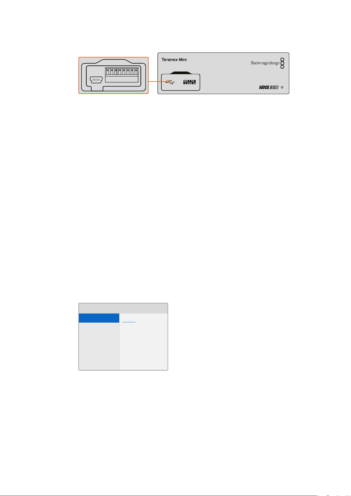
The USB port is still accessible with the Smart Panel attached. To access the port, simply
open the rubber USB dust cover. With the Smart Panel installed, the front panel small switches
are covered up and no longer used. This is because all settings can now be changed via the
LCD menus.
Refer to the ‘changing settings’ section for information on changing settings using an optional
Teranex Mini Smart Panel.
TIP The original basic panel is very strong, so if you need to mount your Teranex Mini IP
Video 12G in the back of a rack system or in areas where there are lots of cables or
activity, you can always reinstall the original basic panel.
1818Settings
Page 19

Smart Panel Features
00:00:00:00
Network IP Video 12G
00:00:00:00
Locking … IP Video 12G
00:00:00:00
No Video IP Video 12G
00:00:00:00
Data rate IP Video 12G
01:23:47:08
2160p59.94 IP Video 12G
LCD Display
The home screen is the first feature you’ll see on your Teranex Mini Smart Panel’s LCD display.
It displays important information, including the source video format, custom name for the unit,
source timecode, and status indicators.
Timecode – The timecode
embedded in the video source
Device name – The name that you have
entered for the unit in the ‘about’ tab
Audio meters – Displays the
audio levels of your video
source connected to your
Teranex Mini IP Video 12G
Source video format
– The format and
frame rate of your video
source connected or
routed to your Teranex
Mini IP Video 12G
1 MENU
2 VIDEO
SET AUDIO
Video monitor – Displays the source video
2160p59.94 IP Video 12G
01:23:47:08
Status Indicators
Indicators on the LCD will show you the current status of the video signal, network connection,
and supported data rate.
If the network is not detected, ‘network’
will be displayed on the LCD screen. Check the unit’s
network settings, and also check the network cable is
properly locked into the Ethernet connectors and
firmly seated.
After the network is successfully connected, you will see
the ‘locking’ indicator as the unit locks to the PTP clock of
your network switch. Depending on the network you are
connecting to, it may take a short period of time to lock.
Once locked to the network switch, the unit will look for a
video signal. If a video signal from the SDI source or
Ethernet connection is not detected, ’no video’ will be
displayed on the LCD screen. Check the SDI source cable
is properly connected.
If the data rate of your SDI source signal is toohigh for
transmission through the selected Ethernet port, ‘data rate’
will be displayed onthe LCD screen. Try changing the
source to an HD signal if using the 1G Ethernet port, or
install an optional 10G Ethernet optical fiber SFP module
for Ultra HD.
1919Settings
Page 20

Control Buttons and Rotary Knob
Main Menu
Direction Destination
ONLow Latency
Network
Information
PTP
Source List
Teranex Mini Smart Panel has a set of buttons and a rotary knob that are used to navigate your
Teranex Mini IP Video 12G’s settings menu.
1 and 2 buttons
Press these buttons to increase or decrease the numeric setting values, or to move up
or down through menu settings.
Set
Press the set button to confirm a settings change.
Menu
Press ‘menu’ to open the settings menu. You can also press the menu button to step
back through menu items.
Video and Audio Buttons
These buttons have no function for Teranex Mini IP Video 12G.
Rotary Knob
Turn the rotary knob clockwise or counter clockwise to navigate through the menu
settings and adjust numeric setting values.
Smart Panel Settings
With the Smart Panel attached you can now change settings using the LCD menus.
1 MENU
MENU
2 VIDEO
SET AUDIO
You can quickly change your settings using an optional Teranex Mini Smart Panel. .
To change a setting using the Smart Panel:
1 Press the menu button to open the settings menu.
2 Use the rotary knob to scroll through the list of settings.
3 Press the set button to select the setting you want to change.
4 Use the rotary knob and set button to make changes to the selected setting, then press
the menu button to back out of the menu settings and return to the home screen.
The settings displayed on the Teranex Mini Smart Panel will differ depending on whether your
Teranex Mini IP Video 12G is set as a ‘source’ or ‘destination’. These settings include:
Direction
This setting lets you to choose whether the unit is a source or a destination.
By default, the unit will be set as a destination. When changing the direction setting,
your Teranex Mini IP Video 12G will restart.
2020Settings
Page 21

Low Latency
1ON2 3 4 5 6 7 8
Destination units can be set to low latency or clean switch modes. Low latency minimizes
any delay in signal from source to destination by only several lines, however when switching
between sources there may be a small disturbance as the source is resynchronized.
Toavoid any disturbance or glitches when changing sources, turn low latency off. This
sets the unit to use clean switch mode, which removes any disturbance when changing
sources using the same video format, but adds 1 to 2 frames of latency.
Network
Select DHCP if you want to let the network automatically identify each unit with its own
IP address, or ‘static’ if you want to enter your own network settings.
Information
This setting is an indicator that provides information on the source Ethernet connection,
such as the source port and IP address.
PTP
The PTP, or precision time protocol setting, indicates whether the unit is a master or
slave. The master is provided by a PTP grandmaster device somewhere in the network.
If your network does not contain a PTP grandmaster, one Teranex Mini IP Video 12G will
be automatically set as the master unit, and all other connected units will lock to that
master unit.
Source List
All available Teranex Mini IP Video 12G source units will be displayed in a list using their
custom name entered using Blackmagic Teranex Setup. On a destination unit, press the
‘set’ button to open the list, select your desired source using the rotary knob, and press
‘set’ again to confirm.
NOTE Even if there is only one source unit connected to the network, you must
still select it from the source list on the destination unit.
Changing Settings using Switches
On the original basic panel of your Teranex Mini you’ll see a rubber dust cover which protects a
set of small switches used for settings. The ‘on/off’ switches are used to configure internal
settings and you can change them using the tip of a pen.
IP Video 12G
Change settings by adjusting switch 1 with a pen
You’ll find a switch settings diagram printed on the base of your IP Video 12G. Ensure your
switch settings correspond to the legend by observing the switch numbers from 1 to 8,
left to right.
2121Settings
Page 22

When using the optional Teranex Mini Smart Panel, the switch settings will be overridden by the
Smart Panel settings. Your Teranex Mini IP Video 12G will retain its last settings whether applied
via switch, Smart Panel or Blackmagic Teranex Setup software. If reverting to switch control
after removing the Smart Panel or updating your converter’s settings via software, you may
need to toggle switch 1 for new settings to take effect.
Even though switch settings are printed on the base of your converter, new features in later
updates can add new settings so it’s worth checking the latest version of this manual for the
most up to date information. You can download the latest version from the Blackmagic Design
support center at www.blackmagicdesign.com/support
Switch Settings
Switch 1 on Teranex Mini IP Video 12G’s small switches sets the direction of the unit to a source
or destination. The default state for switch 1 is ‘off’, which means the unit is set as a destination.
To set the unit as a source, set switch 1 to ‘on’.
IP Video
Refer to the switch legend
printed on the base of your
Teranex Mini IP Video 12G when
DESTINATION
SOURCE
setting the unit as a source or
destination using switch 1
Teranex Mini Rack Shelf
When running multiple sources and destinations, you can use Teranex Mini Rack Shelf to install
your Teranex Mini IP Video 12G units into a broadcast rack or road case. Up to three Teranex
Minis can fit neatly onto each 1RU Teranex Mini Rack Shelf. Teranex Mini IP Video 12G units are
installed into the rack shelf by removing each unit’s rubber feet, if attached, and screwing each
unit into the base of the shelf using the mounting holes underneath. The Teranex Mini Rack
Shelf ships with two original blank panels which you can use to cover gaps if you don’t need to
install additional units.
For more information, check the Blackmagic Design website at www.blackmagicdesign.com
IP Video 12G
Teranex Mini IP Video 12G can be installed in the Teranex Mini Rack Shelf along with other Blackmagic
equipment that shares the same form factor, such as HyperDeck Studio Mini and Teranex Mini Converters
2222Teranex Mini Rack Shelf
Page 23

Setting up and Routing an IP Videohub
Blackmagic Videohub software lets you set up an IP Videohub and make routing changes using
Blackmagic Videohub Control software, or you can also configure a hardware control panel,
such as a Blackmagic Videohub Master Control or Smart Control, so you can make routing
changes from a rack mounted control panel.
Installing Blackmagic Videohub Software
The Videohub software runs on the latest Sierra version of Mac OS, plus 32 and 64 bit versions
of Windows 10. It can be installed from the SD card supplied with your Teranex Mini IP Video 12G,
however we recommend downloading the latest version of the software from the Blackmagic
Design Support Center at www.blackmagicdesign.com/support/family/routing-and-distribution
To install the Videohub software, double
click the installer and follow the prompts
The Blackmagic Videohub folder contains three
Videohub applications. Videohub Control, Videohub
Setup, and Videohub Hardware Panel Setup.
2323Setting up and Routing an IP Videohub
Page 24

Mac OS Installation
1 Double click the installer file from your downloads folder.
2 Follow the install prompts and Mac OS will automatically install the software.
A folder called ‘Blackmagic Videohub’ will be created within your applications folder containing
the following three applications: Videohub Control, Videohub Setup and Videohub Hardware
Panel Setup.
Windows installation
1 Double click the installer file from your downloads folder.
2 Follow the install prompts and accept the terms in the License Agreement and
Windows will automatically install the software.
Click the Windows Start button and then All Programs>Blackmagic Design>Videohub.
Thefollowing three applications are contained within the folder: Videohub Control, Videohub
Setup and Videohub Hardware Panel Setup.
Creating an IP Videohub
To use Blackmagic Videohub Control to make routing changes, you will need to create a
Videohub server on the host computer. This server can then be accessed by any computer or
Blackmagic Videohub control panel on the same network.
To create an IP Videohub using Blackmagic Videohub Setup:
1 Connect your Teranex Mini IP Video 12G units to the network as described in the
getting started section. Also make sure your computer is also connected to the
same network.
2 Launch Blackmagic Videohub Setup.
3 Click on the ‘+’ symbol and select ‘Create IP Videohub’.
Use Blackmagic Videohub Setup to create an IP Videohub so you
can route units using Blackmagic Videohub Control
4 Enter a name for the IP Videohub and select a number of inputs and outputs.
Forexample, 1 input and 1 output if you have 1 source unit and one destination unit
connected to your network.
5 Click ‘add’.
2424Setting up and Routing an IP Videohub
Page 25

NOTE The IP address of the created IP Videohub will share the same IP address of
your computer.
Now that your IP Videohub is created, you can see it in the home page. Click on the
IPVideohub’s icon to open the settings. Here is where the inputs and outputs are defined for
the Videohub server. This is important because it tells Blackmagic Videohub Control what all
the sources and destinations are so that you can route them.
Create an IP Videohub so you can route source and
destinationunits using Blackmagic Videohub Control software
To set the inputs and outputs for the IP Videohub:
1 Click on the ‘inputs’ tab. This lists the number of inputs you defined when
creating the IP Videohub. Now you will need to assign source units to each
input. You will see an icon on the right side of each input name. Click on the
icon to the right of the ‘input 1’ label.
2 A new window will open showing a list of all source units connected to the network.
Choose a source for input 1.
If the source unit does not appear in the list, you can add it manually by entering its IP address.
After selecting the source unit, click ‘save’.
To assign destination units to each output, simply click on the ‘outputs’ tab and follow the same
instructions set out above but for the outputs instead of the inputs. Click ‘save’ after you have
finished setting your inputs and outputs.
TIP If you gave your source and destination units a custom name in Blackmagic Teranex
Setup, the inputs and outputs list will display their custom labels.
2525Setting up and Routing an IP Videohub
Page 26

If you want to add more inputs and outputs to your IP Videohub, or rename your IP Videohub,
simply click on the ‘configure’ tab and edit the settings from there. You can also edit the names
of each input and output by launching Blackmagic Teranex Setup and changing the device
name in the ‘about’ tab.
The inputs and outputs tabs let you assign source
and destination units to each input and output
NOTE The IP address of the created IP Videohub will match your computer’s IP address.
Removing an IP Videohub
After finishing a project, you may want to remove the IP Videohub from your network. Note that
you can only remove the IP Videohub on the local host.
Toremove an IP Videohub:
1 Select the Videohub you would like to remove.
2 Click on the ‘+’ symbol and select ‘Remove IP Videohub’.
3 A dialogue box will ask you to confirm the removal of the IP Videohub from your
computer. Click ‘remove’.
Blackmagic Videohub Control
Using Blackmagic Videohub Control provides a fast and intuitive way to view and switch
between multiple sources and destinations. Videohub Control operates on a single video
output at a time, and selecting a destination pushbutton shows which source is connected to it
by illuminating the source pushbutton. To change the source, simply click on a different source
pushbutton.
2626Blackmagic Videohub Control
Page 27

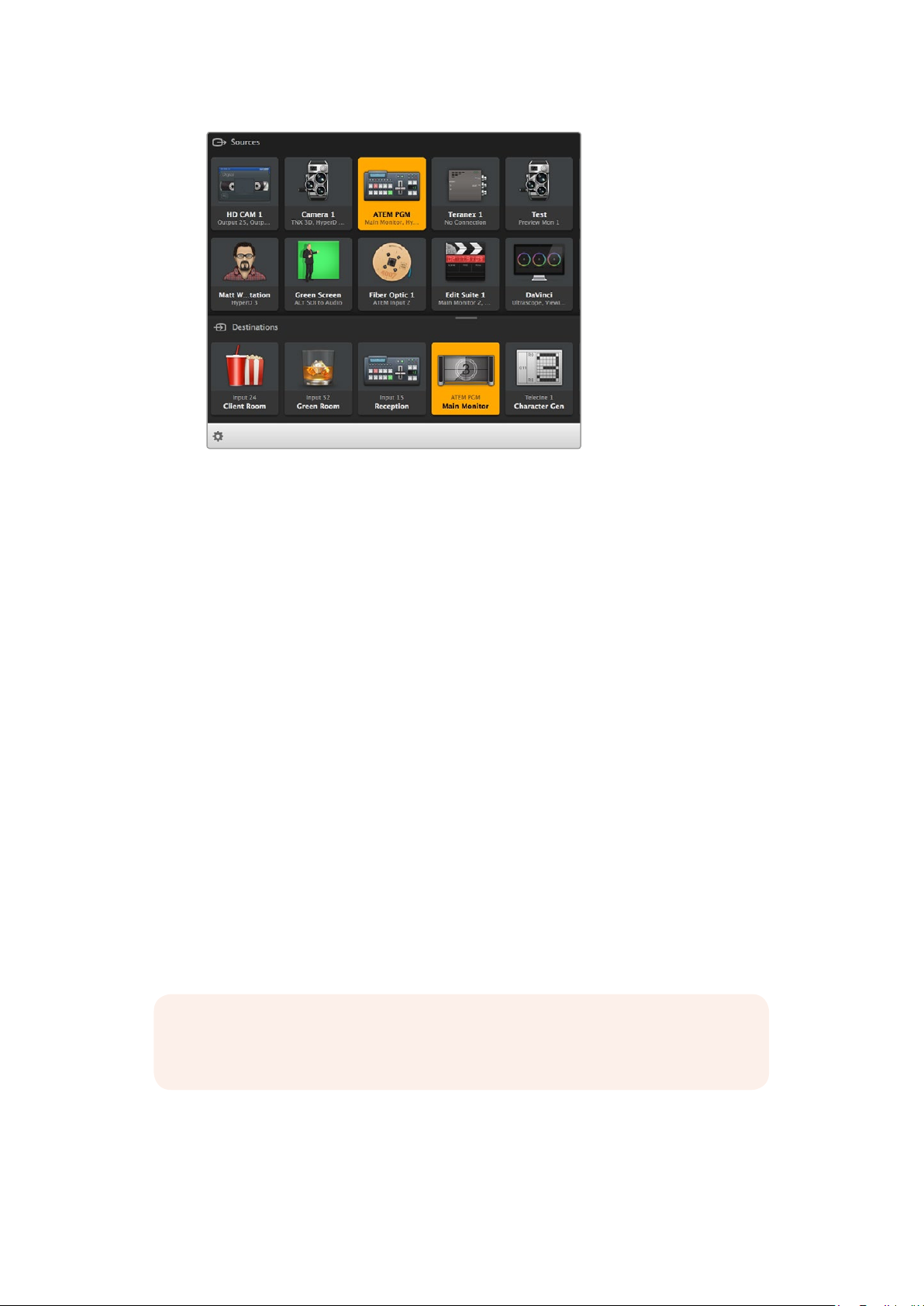
Videohub Control provides an intuitive, icon-driven
representation of the Videohub connections
Selecting a Videohub
Launch Videohub Control and click ‘select Videohub’. If you already have another Videohub
selected, click on the settings icon and choose, ‘select Videohub’.
Click on the IP Videohub you just created. You will now see two panels in the software named
‘sources’ and ‘destinations’, and your IP Video units will appear in each one.
Of course, in the IP Videohub we created there is only one source and one destination, so they
will always be routed to each other, but if you have more source and destination units
connected, you will see all of them as buttons in both areas and they can all be routed.
You have now set up your IP router so you can route source and destination units using
Blackmagic Videohub Control.
Keep reading for more information on how to customize push buttons, including labels and
icons, and general control features.
The video destination button will illuminate when selected and
displays its current source. In the above example, the destination
is the main monitor connected to a DaVinci Resolve suite.
2727Blackmagic Videohub Control
Page 28

Click on the ‘Select Videohub’ button and then select the Videohub you
wish to control. Select ‘edit buttons’ to modify your panel layout.
Adding Pushbuttons
Select the settings button and then select ‘edit buttons’. Click on the add button and choose
whether to add a source or destination pushbutton. The set button window appears and allows
you to set the IP video source or destination icon for the pushbutton.
Viewing Routes
In order to see which IP video source has been routed to a video destination, press the button
in the destinations panel to make the button illuminate. The associated video source button will
illuminate in the sources panel, making it immediately obvious which source is connected to
that destination.
Switching Routes
In order to change the video source from one IP video unit to another one, press a different
source pushbutton in the sources panel to immediately illuminate the new source and route that
source to your selected destination.
Resizing the Interface
Click and drag the bottom right hand corner to proportionally resize the interface to
best fit your screen size. Alternatively, drag a window edge to resize either vertically or
horizontally.
Resizing the Sources and Destinations Areas
Drag the divider bar up and down and use the scroll bars to scroll the respective areas.
Switching Views
You can switch between pushbutton view and list view by clicking the icons in the
bottom right corner.
Using the Dynamic Search
Both the sources and destinations areas contain a search icon, which allows you to
search for text dynamically. This is useful if you have many pushbuttons and quickly
want to locate a pushbutton with a specific name. As you type the name you wish to
search for, the pushbuttons that are displayed will be dynamically filtered.
2828Blackmagic Videohub Control
Page 29

The word ‘ATEM’ is entered into the Destinations
Search Box and the filtered results are displayed
Blackmagic Videohub Control at a Glance
Titl e Bar shows
Videohub type
Sources AreaDestinations Area
Settings
Highlighted Pushbuttons
denote paired connections
Click and drag the window edges to resize Blackmagic Videohub Control to fit
your screen size. Drag the Divider Bar up or down to reveal more or less of the
‘Sources’ and ‘Destinations’ areas and use the Scroll Bars to scroll the areas
Us e TAKE
Sources Area Search
Scrollbars indicate
not all pushbuttons
are visible
Destinations
Area Search
List View
Reveal SourceDivider Bar
Pushbutton View
Settings Menu
Select Videohub
Select from a list of Videohubs that are currently connected to your network.
Save Layout
Save customized pushbutton layouts for the different environments in which you use
your Videohub.
Load Layout
Load previously saved pushbutton layouts.
Edit Buttons
Displays the edit buttons for editing the pushbuttons.
2929Blackmagic Videohub Control
Page 30

Reset All
Displays all of the inputs and outputs of the connected Videohub and replaces
customized icons with the default icon. Source, destination and deck control settings
are maintained.
Click the Settings button to
display the above menu
Edit Buttons
Add
Add a source or destination pushbutton.
Edit
Allows you to set the SDI source or destination, deck control and the icon for the
selected pushbutton.
Lock and Unlock
This feature is not available for an IP Videohub.
Clear
Deletes source, destination and deck control settings as well as the icon for the
selected pushbutton.
Remove
Removes the selected pushbutton.
Done
Click the Done button to exit the edit mode.
Click on the settings icon and select ‘edit buttons’
to open the pushbutton customization settings
3030Blackmagic Videohub Control
Page 31
Using Pushbuttons
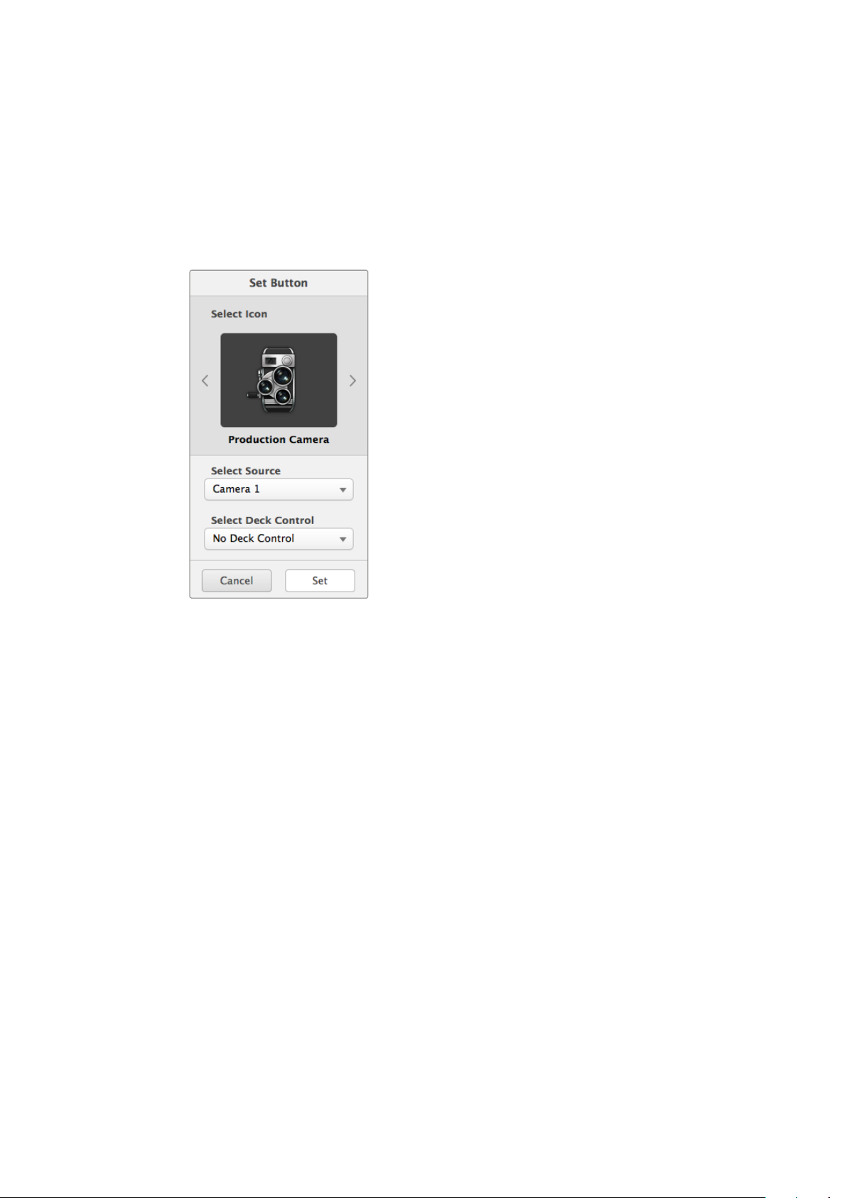
Adding and Editing Pushbuttons
Click on the settings icon and then select ‘edit buttons’. Click on the add button and
choose whether to add a source or destination pushbutton, or click ‘edit’ to modify an
existing one.
The set button window appears and allows you to set the IP video source or
destination, control and the icon for the pushbutton.
The set button window allows icon customization
for sources and destination pushbuttons
Moving Pushbuttons
When editing or adding pushbuttons, you can also reposition them by clicking on the
respective button and dragging it to a new position.
Once you are satisfied with your changes, click ‘done’ to return the software to
standard routing.
Viewing and Switching Routes
Viewing Routes
In order to see which IP video source has been routed to a video destination, such as a
monitor, press the button in the destinations panel to make the button illuminate. The
associated video source button will illuminate in the sources panel, making it
immediately obvious which source is connected to the monitor.
Reveal Source
If you select a destination but the source is currently positioned offscreen, clicking the
reveal source button will scroll the sources area to display the source pushbutton.
Switching Routes
In order to change the video source from a tape deck to a video camera, press a
camera pushbutton in the sources panel. The camera pushbutton will illuminate,
indicating that it is now routed to the video monitor. The tape deck button will no longer
be illuminated and will be disconnected from the video monitor.
3131Blackmagic Videohub Control
Page 32

Use TAKE Confirmation before Switching Routes
You may wish to enable the ‘use take’ button to help prevent unintentional changes to
video routes. Once enabled, any attempt to change a video route using a pushbutton
will cause a red ‘take’ button to appear. Select the button to confirm or click the current
source or destination pushbutton to cancel.
Using a Videohub Hardware Panel
You can also control your IP Videohub router using a Videohub hardware control panel, such as
a Blackmagic Videohub Master Control or Smart Control. This lets you route all your sources
and destinations from one single rack mounted control panel.
SRC CLEAR
LEVEL DEST
1 2 3 4 5 6 7 8 9 0
Using an optional control panel like Videohub Master Control lets you route all your
IP Video sources and destinations from a rack mounted hardware control panel
All you need to do is tell the hardware panel the IP Videohub router you want it to control.
Thisis done by entering the IP Videohub’s IP address in the panel’s network settings via
Blackmagic Videohub Hardware Panel Setup.
To set the IP address in the panel’s network settings:
TAKE
1 Launch Blackmagic Videohub Hardware Panel Setup.
2 Make sure your hardware panel is connected to your computer via Ethernet and is
selected in the left column of the hardware panel’s setup settings.
3 In the hardware panel network settings you will see a setting at the bottom of the list for
remote Videohub IP. Click in the edit window and enter your IP Videohub’s IP address.
When your hardware panel connects with the IP Videohub, the indicator on right side of the
IPaddress setting will illuminate green.
Now you can route your IP Video sources and destinations using the Videohub hardware
control panel.
Set the remote Videohub IP setting in Blackmagic
Videohub Hardware Panel Setup so you can route your
IP video using a Videohub hardware control panel
3232Blackmagic Videohub Control
Page 33

Teranex Mini IP Video 12G Block Diagram
Source
SDI In
SDI Out 1
SDI Out 2
Optional
Smart Panel
and LCD
Destination
SDI Out 1
SDI Out 2
USB
Equalizer,
Re-Clocker and
10 bit De-Serializer
Central
Processor and
Firmware
Video
Clock Recovery
10 bit Serializer
and Cable Driver
Video TICO Encoder
and IP Encapsulation
Multiplexer
Video TICO Decoder
and IP Decapsulation
Optional
10G SFP Ethernet
1G Ethernet
with Power
Optional
10G SFP Ethernet
USB
Optional
Smart Panel
and LCD
Central
Processor and
Firmware
Multiplexer
1G Ethernet
with Power
3333Teranex Mini IP Video 12G Block Diagram
Page 34

Updating the Internal Software
Occasionally, updates for your Teranex Mini IP Video 12G’s internal software will be available on
the Blackmagic Design website. We recommend downloading the software and updating the
internal software so you can benefit from new features and improvements.
The latest software can be downloaded from the Blackmagic Design Support Center at
www.blackmagicdesign.com/support
To update the internal software:
1 Download and install the latest version of Teranex Mini Setup. Refer to the ‘settings’
section for information on how to install Teranex Mini Setup.
2 Power your Teranex Mini IP Video 12G.
NOTE It is important to ensure that power is connected to your Teranex Mini
IPVideo 12G before connecting a USB cable between the computer
and the unit.
3 Attach a USB cable from your computer to the unit, or connect via Ethernet, and launch
the Blackmagic Teranex Setup utility.
If your Teranex Mini IP Video 12G is not detected, Blackmagic Teranex Setup will report ‘no
converter connected’ in the title bar. When the unit is detected, the name of the unit and its
image will appear.
If Blackmagic Teranex Setup contains newer internal software than that currently installed in
your Teranex Mini IP Video 12G, it will prompt you to update. Just follow the on screen
instructions to complete the update. Once the internal software update is complete, you will be
able to make adjustments to the unit using the Blackmagic Teranex Setup utility.
3434Updating the internal Software
Page 35

Appendix
Connecting a Grand-Master Clock
If connecting a grand master clock to your switch, it should allow unicast delay request packets.
Packet fields recommended values:
defaultDS.priority1: 128
defaultDS.priority1: 128
defaultDS.domainNumber: 127
defaultDS.slaveOnly: FALSE
portDS.logAnnounceInterval: -2 (this is 250ms)
portDS.announceReceiptTimeout: 3 (the number of announce intervals that have to
pass without receipt of an announce message before the occurrence of the event
ANNOUNCE_RECEIPT_TIMEOUT_EXPIRES)
portDS.logSyncInterval: -3 (this is 125ms)
portDS.delayMechanism: 01h (we do only Delay request-response, aka End-to-End)
portDS.logMinPDelayReqInterval: -3 (equal to portDS.logSyncInterval)
transparentClockDefaultDS.delayMechanism: 01h (we do only End-to-End)
transparentClockDefaultDS.primaryDomain: 127 (same as defaultDS.domainNumber)
portDS.logMinDelayReqInterval: -3 (equal to portDS.logSyncInterval)
3535Appendix
Page 36

Help
Getting Help
The fastest way to obtain help is to go to the Blackmagic Design online support pages and
check the latest support material available for your Teranex Mini.
Blackmagic Design Online Support Pages
The latest manual, software and support notes can be found at the Blackmagic Design support
center at www.blackmagicdesign.com/support.
Contacting Blackmagic Design Support
If you can’t find the help you need in our support material, please use the ‘Send us an email’
button on the support page to email a support request. Alternatively, click on the ‘Find your
local support team’ button on the support page and call your nearest Blackmagic Design
support office.
Checking the Software Version CurrentlyInstalled
To check which version of Blackmagic Teranex Setup software is installed on your computer,
open the About Blackmagic Teranex Setup window.
On a Mac, open Blackmagic Teranex Setup from the Applications folder. Select About
Blackmagic Teranex Setup from the application menu to reveal the version number.
On Windows 7, open Blackmagic Teranex Setup from your Start menu. Click on the Help menu
and select About Blackmagic Teranex Setup to reveal the version number.
On Windows 8, open Blackmagic Teranex Setup from the Blackmagic Teranex Setup tile on
your Start page. Click on the Help menu and select About Blackmagic Teranex Setup to reveal
the version number.
How to Get the Latest Software Updates
After checking the version of Blackmagic Teranex Setup software installed on your computer,
please visit the Blackmagic Design support center at www.blackmagicdesign.com/support to
check for the latest updates. While it is usually a good idea to run the latest updates, it is wise to
avoid updating any software if you are in the middle of an important project.
3636Help
Page 37

Regulatory Notices and Safety Information
Regulatory Notices
Disposal of waste of electrical and electronic equipment within the European union.
The symbol on the product indicates that this equipment must not be disposed of with
other waste materials. In order to dispose of your waste equipment, it must be handed
over to a designated collection point for recycling. The separate collection and
recycling of your waste equipment at the time of disposal will help conserve natural
resources and ensure that it is recycled in a manner that protects human health and the
environment. Formore information about where you can drop off your waste
equipment for recycling, please contact your local city recycling office or the dealer
from whom you purchased the product.
This equipment has been tested and found to comply with the limits for a Class A
digitaldevice, pursuant to Part 15 of the FCC rules. These limits are designed to provide
reasonable protection against harmful interference when the equipment is operated in
a commercial environment. This equipment generates, uses, and can radiate radio
frequency energy and, if not installed and used in accordance with the instructions,
maycause harmful interference to radio communications. Operation of this product in a
residential area is likely to cause harmful interference, in which case the user will be
required to correct the interference at personal expense.
Operation is subject to the following two conditions:
1 This device may not cause harmful interference.
2 This device must accept any interference received, including interference that may
cause undesired operation.
Connection to HDMI interfaces must be made with high quality shielded HDMI cables.
Safety Information
This equipment must be connected to a mains socket outlet with a protective earth
connection.
To reduce the risk of electric shock, do not expose this equipment to dripping or
splashing.
This equipment is suitable for use in tropical locations with an ambient temperature of
up to 40ºC.
Ensure that adequate ventilation is provided around the product and is not restricted.
When rack mounting, ensure the ventilation is not restricted by adjacent equipment.
No operator serviceable parts inside. Refer servicing to your local Blackmagic Design
service centre.
Use only at altitudes not more than 2000m above sea level.
This product has the facility to connect small form-factor transceiver (SFP) optical fibre
modules. Only use Laser class 1 optical SFP modules.
3737Regulatory Notices and Safety Information
Page 38

Warranty
36 Month Limited Warranty
Blackmagic Design warrants that Teranex Minis will be free from defects in materials and
workmanship for a period of 36 months from the date of purchase excluding connectors,
cables, fiber optic modules, fuses and batteries which will be free from defects in materials and
workmanship for a period of 12 months from the date of purchase. If a product proves to be
defective during this warranty period, Blackmagic Design, at its option, either will repair the
defective product without charge for parts and labor, or will provide a replacement in exchange
for the defective product.
In order to obtain service under this warranty, you the Customer, must notify Blackmagic Design
of the defect before the expiration of the warranty period and make suitable arrangements for
the performance of service. The Customer shall be responsible for packaging and shipping the
defective product to a designated service center nominated by Blackmagic Design, with
shipping charges pre paid. Customer shall be responsible for paying all shipping charges,
insurance, duties, taxes, and any other charges for products returned to us for any reason.
This warranty shall not apply to any defect, failure or damage caused by improper use or
improper or inadequate maintenance and care. Blackmagic Design shall not be obligated to
furnish service under this warranty: a) to repair damage resulting from attempts by personnel
other than Blackmagic Design representatives to install, repair or service the product, b) to
repair damage resulting from improper use or connection to incompatible equipment, c) to
repair any damage or malfunction caused by the use of non Blackmagic Design parts or
supplies, or d) to service a product that has been modified or integrated with other products
when the effect of such a modification or integration increases the time or difficulty of servicing
the product.
THIS WARRANTY IS GIVEN BY BLACKMAGIC DESIGN IN LIEU OF ANY OTHER WARRANTIES,
EXPRESS OR IMPLIED. BLACKMAGIC DESIGN AND ITS VENDORS DISCLAIM ANY IMPLIED
WARRANTIES OF MERCHANTABILITY OR FITNESS FOR A PARTICULAR PURPOSE.
BLACKMAGIC DESIGN’S RESPONSIBILITY TO REPAIR OR REPLACE DEFECTIVE PRODUCTS IS
THE WHOLE AND EXCLUSIVE REMEDY PROVIDED TO THE CUSTOMER FOR ANY INDIRECT,
SPECIAL, INCIDENTAL OR CONSEQUENTIAL DAMAGES IRRESPECTIVE OF WHETHER
BLACKMAGIC DESIGN OR THE VENDOR HAS ADVANCE NOTICE OF THE POSSIBILITY OF
SUCH DAMAGES. BLACKMAGIC DESIGN IS NOT LIABLE FOR ANY ILLEGAL USE OF
EQUIPMENT BY CUSTOMER. BLACKMAGIC IS NOT LIABLE FOR ANY DAMAGES RESULTING
FROM USE OF THIS PRODUCT. USER OPERATES THIS PRODUCT AT OWN RISK.
© Copyright 2017 Blackmagic Design. A ll rights reserved. ‘Blackmagic Design’, ‘DeckLink’, ‘HDLink ’, ‘Workgroup Videohub’,
‘Multibridge Pro’, ‘Multibridge Extreme’, ‘Intensity’ and ‘Leading t he creat ive video revolution’ are regis tered trademarks in the
US and other countries. All other company and product names may be trade marks of t heir respect ive companies with which
they are associated.
3838Warranty
 Loading...