Blackmagic Design Studio Camera 4k Plus, Studio Camera 4K Pro Installation and Operation Manual

Blackmagic Design Studio Camera 4k Plus, Studio Camera 4K Pro Installation and Operation Manual

July 2021

Installation and Operation Manual

Blackmagic

Studio Cameras

Blackmagic Studio Cameras

Languages

To go directly to your preferred language, simply click on the hyperlinks listed in the contents below.

English

3


104

Français

206

Deutsch

308

Español

410


512


614

Русский

716

Italiano

818

Português

920

Türkçe

1022

Welcome

Thank you for purchasing a Blackmagic Studio Camera!

Blackmagic Studio Cameras have the same features as large studio cameras, miniaturized into a single compact and portable design.

With increased dynamic range and Blackmagic Design color science, the cameras can handle extremely difficult lighting conditions while producing cinematic looking images. The dual gain sensor supports ISO up to 25,600 so you can create amazing images even in dimly lit venues.

Advanced features include talkback, tally, camera control, built in color corrector, Blackmagic RAW recording to USB disks and much more! You can even add a focus and zoom demand for lens control!

We hope you use your new camera for some amazing live productions and produce some fantastic looking work! We are extremely excited to see what creative work you produce!

Grant Petty

CEO Blackmagic Design

Contents

Which Studio Camera are you using?

5

Getting Started

5

Attaching a Lens

6

Plugging in Power

7

Turning Your Camera On

7

Setting the Frame Rate and Resolution

8

Connecting to an ATEM switcher

9

Connecting a Talkback Headset

10

Setting the ATEM Camera ID

11

Checking your Setup

11

Studio Camera Connections

13

Left Panel

13

Right Panel

14

5 Pin XLR Talkback Connector


Pinout Diagram

15

Using Studio Camera Controls

15

Touchscreen Controls

18

Changing Settings using the Head


up Display

18

Head up Display Settings

19

Menu Settings

38

Record Settings

39

Blackmagic RAW

40

Recording to Blackmagic RAW

40

Record Duration

43

File Naming Convention

47

Monitor Settings

47

Audio Settings

56

Setup Settings

59

Presets

66

LUTs

68

Using the Sun Hood

71

Blackmagic Zoom and Focus Demands

72

Connecting and Attaching to your


Camera

73

Using Blackmagic Focus Demand

75

Using Blackmagic Zoom Demand

76

Blackmagic Camera Setup

78

How to Update your Camera’s


Internal Software

78

Using ATEM Software Control

79

Camera Control

79

Using Camera Control

79

DaVinci Resolve Primary Color Corrector  83

Developer Information

86

Blackmagic SDI Camera Control Protocol  86

Example Protocol Packets

95

Blackmagic Embedded Tally


Control Protocol

96

Connecting Tally using the


Blackmagic 3G-SDI Shield for Arduino

98

Help

100

Regulatory Notices

101

Safety Information

102

Warranty

103

Blackmagic Studio Cameras

4

Which Studio Camera are you using?

Blackmagic Studio Cameras are designed to have similar features to large studio cameras, miniaturized into a compact and more portable design. The cameras also feature wide dynamic range and advanced color science, so they can handle difficult lighting conditions while producing cinematic looking images.

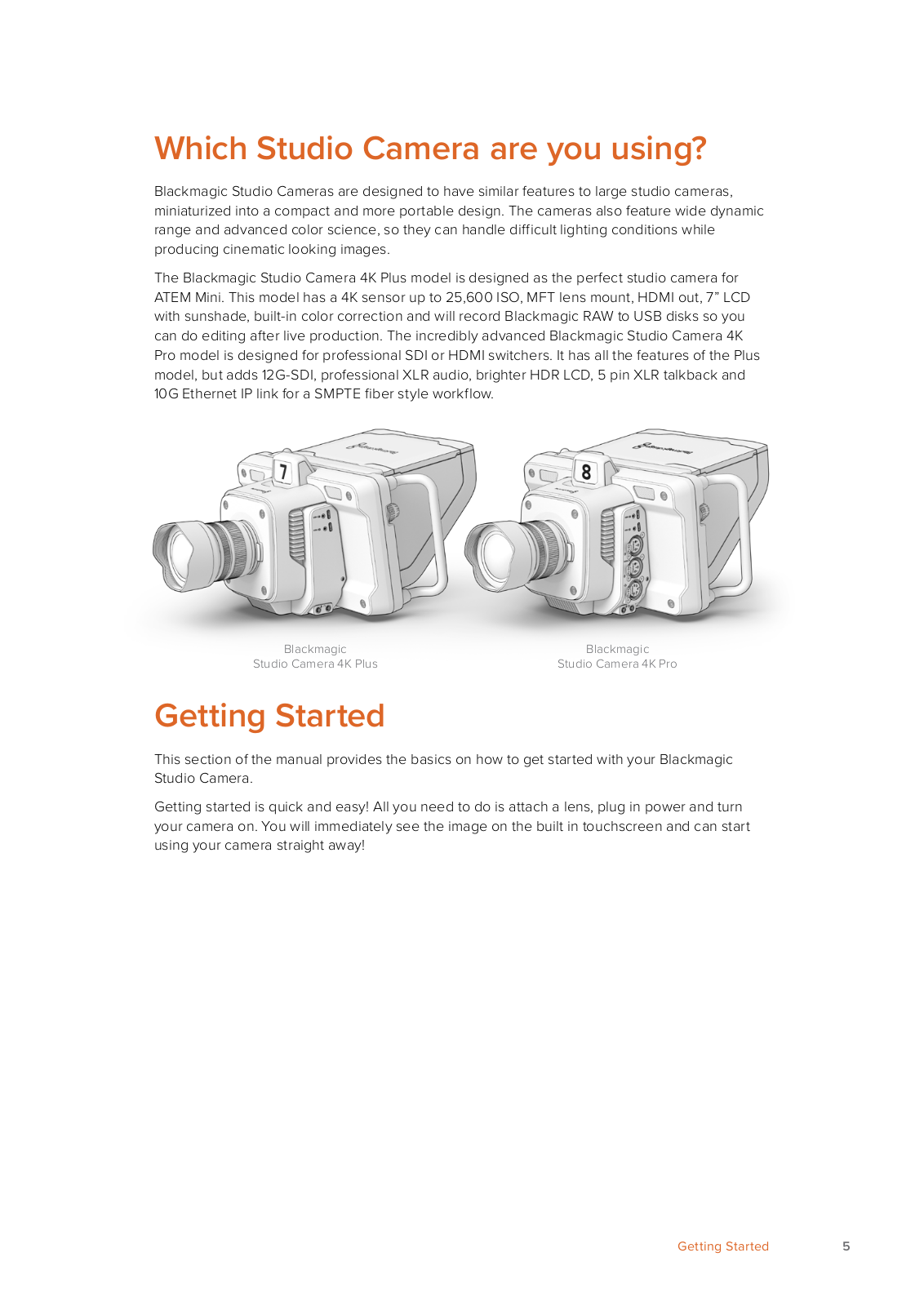
The Blackmagic Studio Camera 4K Plus model is designed as the perfect studio camera for ATEM Mini. This model has a 4K sensor up to 25,600 ISO, MFT lens mount, HDMI out, 7” LCD with sunshade, built-in color correction and will record Blackmagic RAW to USB disks so you can do editing after live production. The incredibly advanced Blackmagic Studio Camera 4K Pro model is designed for professional SDI or HDMI switchers. It has all the features of the Plus model, but adds 12G-SDI, professional XLR audio, brighter HDR LCD, 5 pin XLR talkback and 10G Ethernet IP link for a SMPTE fiber style workflow.

Blackmagic

Blackmagic

Studio Camera 4K Plus

Studio Camera 4K Pro

Getting Started

This section of the manual provides the basics on how to get started with your Blackmagic Studio Camera.

Getting started is quick and easy! All you need to do is attach a lens, plug in power and turn your camera on. You will immediately see the image on the built in touchscreen and can start using your camera straight away!

Getting Started

5

Attaching a Lens

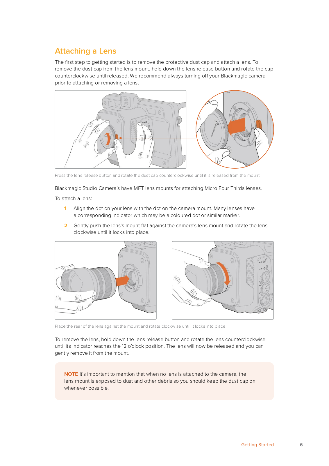
The first step to getting started is to remove the protective dust cap and attach a lens. To remove the dust cap from the lens mount, hold down the lens release button and rotate the cap counterclockwise until released. We recommend always turning off your Blackmagic camera prior to attaching or removing a lens.

Press the lens release button and rotate the dust cap counterclockwise until it is released from the mount

Blackmagic Studio Camera’s have MFT lens mounts for attaching Micro Four Thirds lenses. To attach a lens:

1Align the dot on your lens with the dot on the camera mount. Many lenses have a corresponding indicator which may be a coloured dot or similar marker.

2Gently push the lens’s mount flat against the camera’s lens mount and rotate the lens clockwise until it locks into place.

Place the rear of the lens against the mount and rotate clockwise until it locks into place

To remove the lens, hold down the lens release button and rotate the lens counterclockwise until its indicator reaches the 12 o’clock position. The lens will now be released and you can gently remove it from the mount.

NOTE It’s important to mention that when no lens is attached to the camera, the lens mount is exposed to dust and other debris so you should keep the dust cap on whenever possible.

Getting Started

6

Plugging in Power

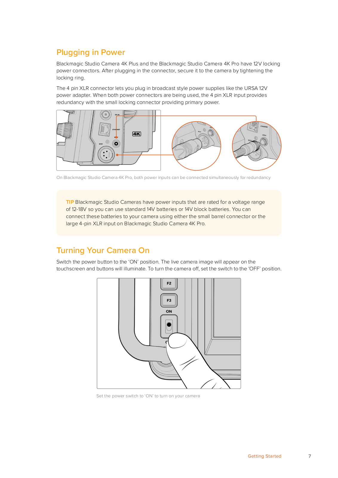
Blackmagic Studio Camera 4K Plus and the Blackmagic Studio Camera 4K Pro have 12V locking power connectors. After plugging in the connector, secure it to the camera by tightening the locking ring.

The 4 pin XLR connector lets you plug in broadcast style power supplies like the URSA 12V power adapter. When both power connectors are being used, the 4 pin XLR input provides redundancy with the small locking connector providing primary power.

On Blackmagic Studio Camera 4K Pro, both power inputs can be connected simultaneously for redundancy

TIP Blackmagic Studio Cameras have power inputs that are rated for a voltage range of 12-18V so you can use standard 14V batteries or 14V block batteries. You can connect these batteries to your camera using either the small barrel connector or the large 4-pin XLR input on Blackmagic Studio Camera 4K Pro.

Turning Your Camera On

Switch the power button to the ‘ON’ position. The live camera image will appear on the touchscreen and buttons will illuminate. To turn the camera off, set the switch to the ‘OFF’ position.

Set the power switch to ‘ON’ to turn on your camera

Getting Started

7

Setting the Frame Rate and Resolution

With a lens attached and the camera turned on, the next step is to set the video format for the HDMI or SDI output. This is the video standard and frame rate you will be sending to destination equipment such as an ATEM switcher, a monitor, or HyperDeck disk recorder.

To set the frame rate:

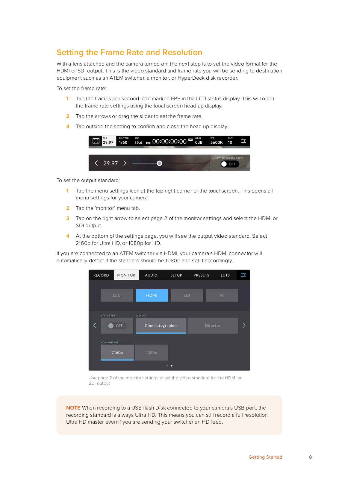
1Tap the frames per second icon marked FPS in the LCD status display. This will open the frame rate settings using the touchscreen head up display.

2Tap the arrows or drag the slider to set the frame rate.

3Tap outside the setting to confirm and close the head up display.

To set the output standard:

1Tap the menu settings icon at the top right corner of the touchscreen. This opens all menu settings for your camera.

2Tap the ‘monitor’ menu tab.

3Tap on the right arrow to select page 2 of the monitor settings and select the HDMI or SDI output.

4At the bottom of the settings page, you will see the output video standard. Select 2160p for Ultra HD, or 1080p for HD.

If you are connected to an ATEM switcher via HDMI, your camera’s HDMI connector will automatically detect if the standard should be 1080p and set it accordingly.

Use page 2 of the monitor settings to set the video standard for the HDMI or

SDI output

NOTE When recording to a USB flash Disk connected to your camera’s USB port, the recording standard is always Ultra HD. This means you can still record a full resolution Ultra HD master even if you are sending your switcher an HD feed.

Getting Started

8

Connecting to an ATEM switcher

Connecting to an ATEM switcher lets you switch multiple studio cameras in your live production and control them using the switcher or ATEM Software Control. Tally signals are sent back to your camera so your camera’s tally light illuminates when it is switched on air.

Connecting via HDMI

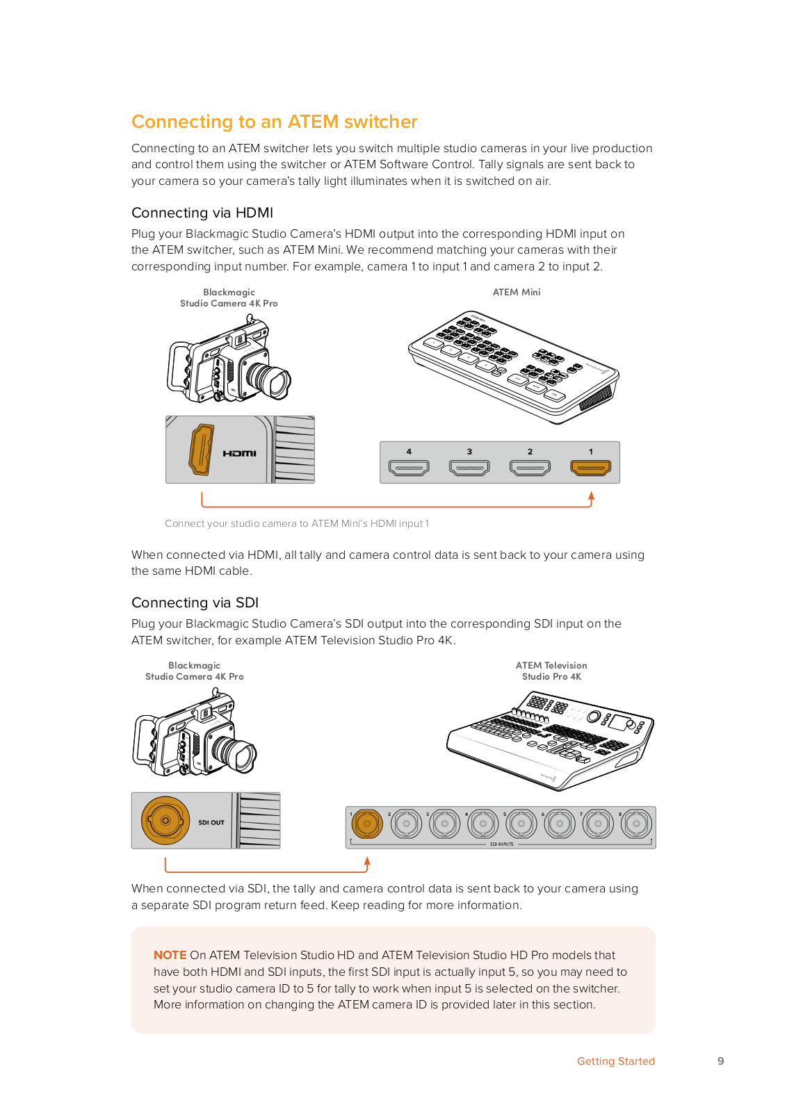
Plug your Blackmagic Studio Camera’s HDMI output into the corresponding HDMI input on the ATEM switcher, such as ATEM Mini. We recommend matching your cameras with their corresponding input number. For example, camera 1 to input 1 and camera 2 to input 2.

Blackmagic

Studio Camera 4K Pro

Connect your studio camera to ATEM Mini’s HDMI input 1

When connected via HDMI, all tally and camera control data is sent back to your camera using the same HDMI cable.

Connecting via SDI

Plug your Blackmagic Studio Camera’s SDI output into the corresponding SDI input on the ATEM switcher, for example ATEM Television Studio Pro 4K.

Blackmagic

ATEM Television

Studio Camera 4K Pro

Studio Pro 4K

2

3

4

5

6

7

8

SDI INPUTS

When connected via SDI, the tally and camera control data is sent back to your camera using a separate SDI program return feed. Keep reading for more information.

NOTE On ATEM Television Studio HD and ATEM Television Studio HD Pro models that have both HDMI and SDI inputs, the first SDI input is actually input 5, so you may need to set your studio camera ID to 5 for tally to work when input 5 is selected on the switcher. More information on changing the ATEM camera ID is provided later in this section.

Getting Started

9

Connecting the Program Return Feed

The program return feed lets you monitor the program output from your switcher on your studio camera’s LCD. The program output also contains tally, talkback, camera control data, plus timecode and reference genlock signals.

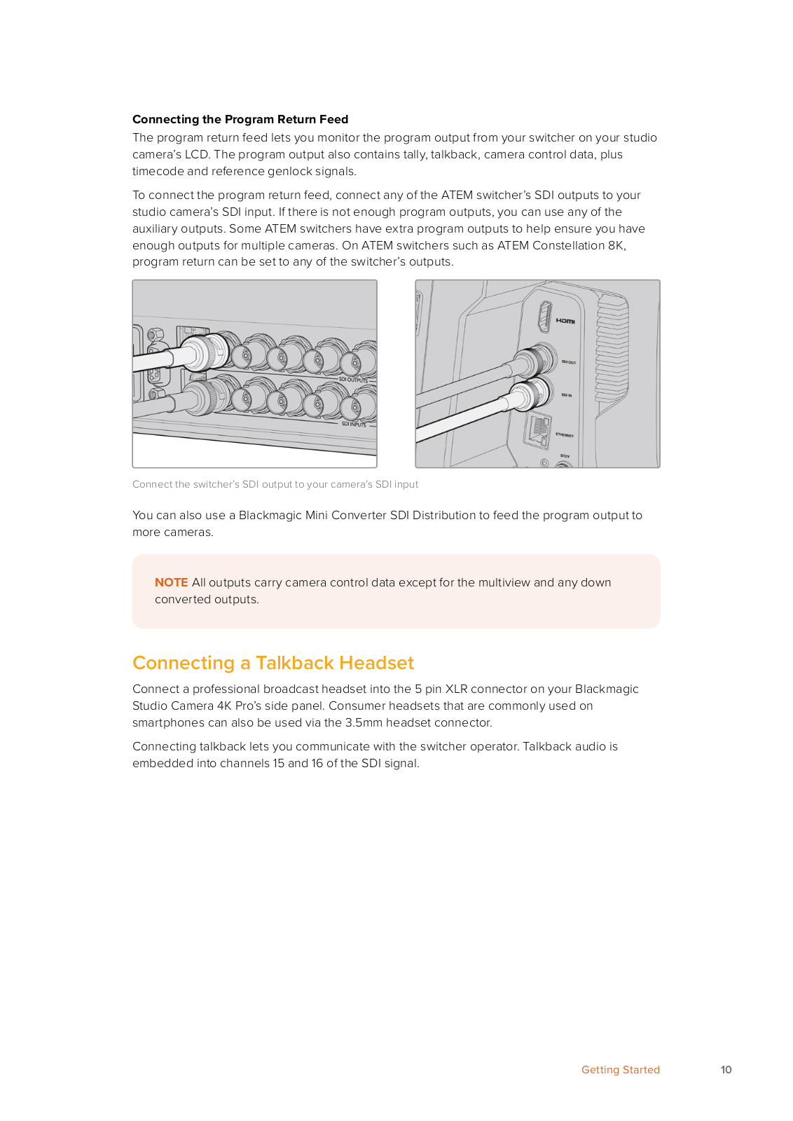
To connect the program return feed, connect any of the ATEM switcher’s SDI outputs to your studio camera’s SDI input. If there is not enough program outputs, you can use any of the auxiliary outputs. Some ATEM switchers have extra program outputs to help ensure you have enough outputs for multiple cameras. On ATEM switchers such as ATEM Constellation 8K, program return can be set to any of the switcher’s outputs.

Connect the switcher’s SDI output to your camera’s SDI input

You can also use a Blackmagic Mini Converter SDI Distribution to feed the program output to more cameras.

NOTE All outputs carry camera control data except for the multiview and any down converted outputs.

Connecting a Talkback Headset

Connect a professional broadcast headset into the 5 pin XLR connector on your Blackmagic Studio Camera 4K Pro’s side panel. Consumer headsets that are commonly used on smartphones can also be used via the 3.5mm headset connector.

Connecting talkback lets you communicate with the switcher operator. Talkback audio is embedded into channels 15 and 16 of the SDI signal.

Getting Started

10

You can use common 3.5mm TRRS phone headsets that have a built in microphone via the 3.5mm jack, or use a 5 pin XLR talkback headset on the Blackmagic Studio Camera 4K Pro

Setting the ATEM Camera ID

The ATEM camera ID is a setting in your camera’s menu settings that determines which SDI input your studio camera is connected to on the ATEM switcher. When the camera ID

corresponds to the switcher’s input number, your camera will detect tally data for that input and the tally light will work correctly on your camera.

When connected to an ATEM switcher via HDMI, you don’t need to worry about setting the camera ID as the switcher can detect the input each camera is connected to and assign tally data accordingly.

For more information on changing the ATEM camera ID, refer to the ‘menu settings’ section.

Change the ATEM camera ID using your studio camera’s ‘setup’ settings

Checking your Setup

Now that everything is plugged in and ATEM Camera IDs are correct, you can check that everything is working.

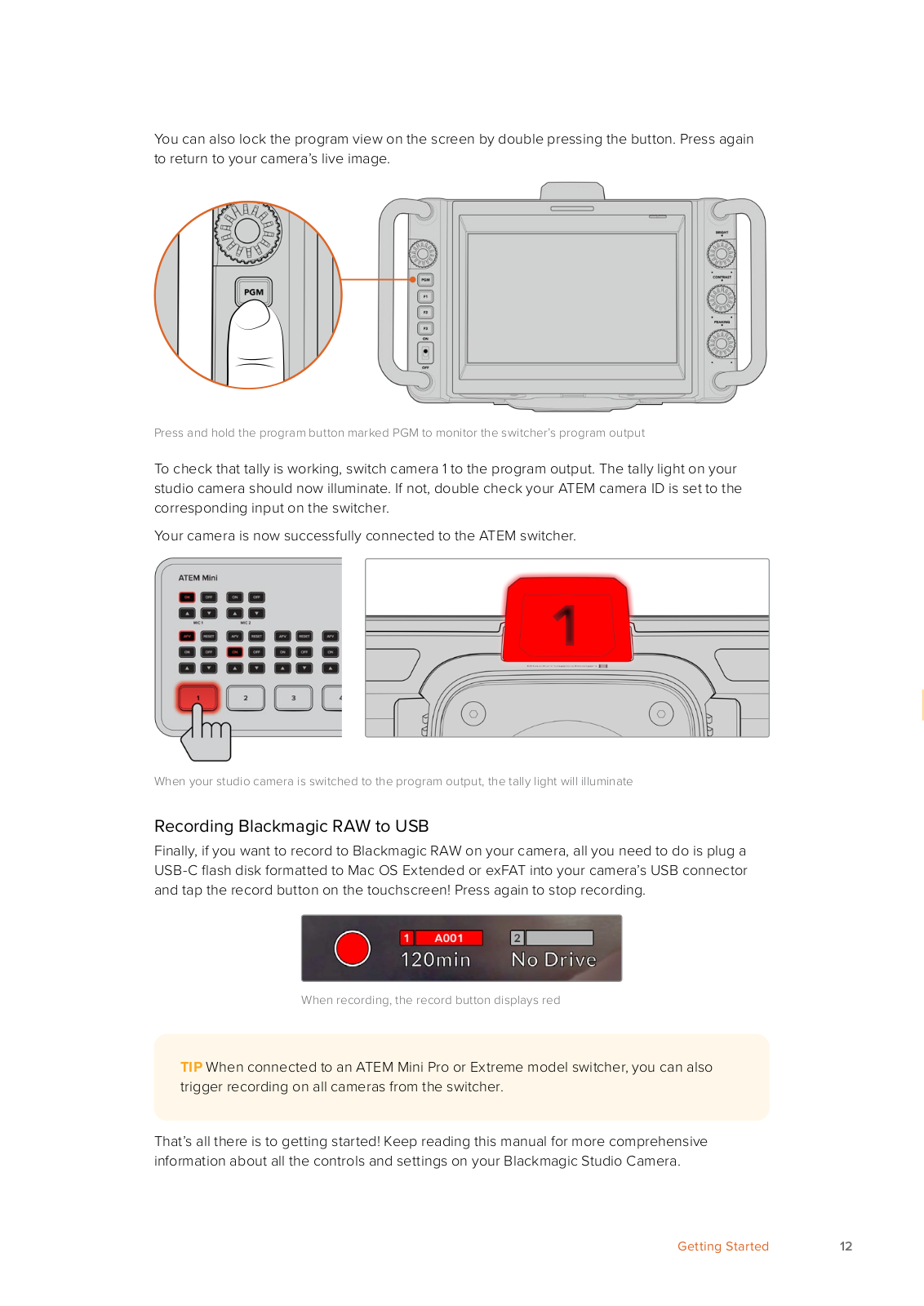
On Blackmagic Studio Camera 4K Pro, a fast way to check is to press and hold the program button marked PGM on your camera, then switch color bars to the program output on your ATEM switcher. If you see color bars on your camera, you know the program output is working properly with your camera.

Getting Started

11

You can also lock the program view on the screen by double pressing the button. Press again to return to your camera’s live image.

Press and hold the program button marked PGM to monitor the switcher’s program output

To check that tally is working, switch camera 1 to the program output. The tally light on your studio camera should now illuminate. If not, double check your ATEM camera ID is set to the corresponding input on the switcher.

Your camera is now successfully connected to the ATEM switcher.

When your studio camera is switched to the program output, the tally light will illuminate

Recording Blackmagic RAW to USB

Finally, if you want to record to Blackmagic RAW on your camera, all you need to do is plug a USB-C flash disk formatted to Mac OS Extended or exFAT into your camera’s USB connector and tap the record button on the touchscreen! Press again to stop recording.

When recording, the record button displays red

TIP When connected to an ATEM Mini Pro or Extreme model switcher, you can also trigger recording on all cameras from the switcher.

That’s all there is to getting started! Keep reading this manual for more comprehensive information about all the controls and settings on your Blackmagic Studio Camera.

Getting Started

12

Studio Camera Connections

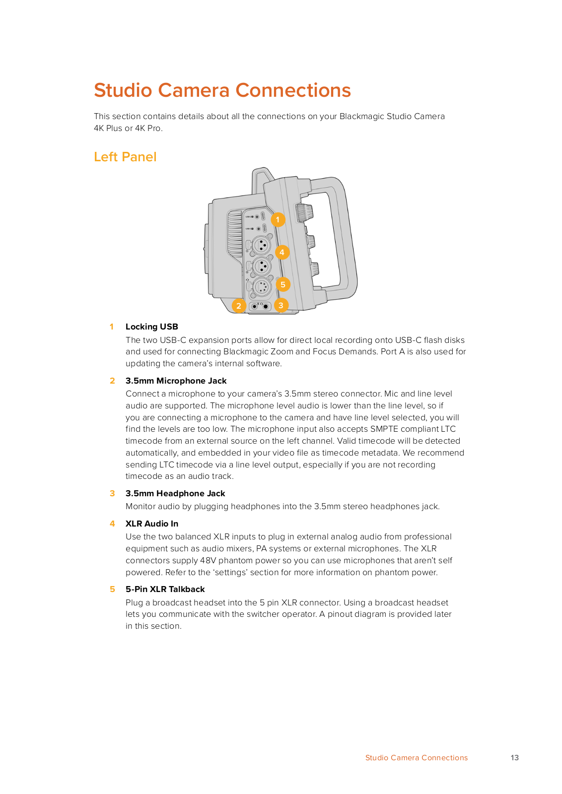
This section contains details about all the connections on your Blackmagic Studio Camera 4K Plus or 4K Pro.

Left Panel

1

4

5

2 3

1Locking USB

The two USB-C expansion ports allow for direct local recording onto USB-C flash disks and used for connecting Blackmagic Zoom and Focus Demands. Port A is also used for updating the camera’s internal software.

23.5mm Microphone Jack

Connect a microphone to your camera’s 3.5mm stereo connector. Mic and line level audio are supported. The microphone level audio is lower than the line level, so if you are connecting a microphone to the camera and have line level selected, you will find the levels are too low. The microphone input also accepts SMPTE compliant LTC timecode from an external source on the left channel. Valid timecode will be detected

automatically, and embedded in your video file as timecode metadata. We recommend sending LTC timecode via a line level output, especially if you are not recording timecode as an audio track.

33.5mm Headphone Jack

Monitor audio by plugging headphones into the 3.5mm stereo headphones jack.

4XLR Audio In

Use the two balanced XLR inputs to plug in external analog audio from professional equipment such as audio mixers, PA systems or external microphones. The XLR connectors supply 48V phantom power so you can use microphones that aren’t self powered. Refer to the ‘settings’ section for more information on phantom power.

55-Pin XLR Talkback

Plug a broadcast headset into the 5 pin XLR connector. Using a broadcast headset lets you communicate with the switcher operator. A pinout diagram is provided later in this section.

Studio Camera Connections

13

Right Panel

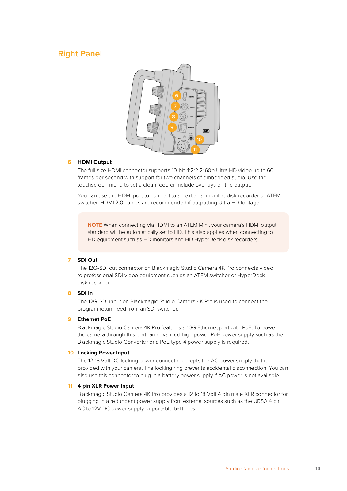
6

7

8

9

10

11

6HDMI Output

The full size HDMI connector supports 10-bit 4:2:2 2160p Ultra HD video up to 60 frames per second with support for two channels of embedded audio. Use the touchscreen menu to set a clean feed or include overlays on the output.

You can use the HDMI port to connect to an external monitor, disk recorder or ATEM switcher. HDMI 2.0 cables are recommended if outputting Ultra HD footage.

NOTE When connecting via HDMI to an ATEM Mini, your camera’s HDMI output standard will be automatically set to HD. This also applies when connecting to HD equipment such as HD monitors and HD HyperDeck disk recorders.

7SDI Out

The 12G-SDI out connector on Blackmagic Studio Camera 4K Pro connects video to professional SDI video equipment such as an ATEM switcher or HyperDeck disk recorder.

8SDI In

The 12G-SDI input on Blackmagic Studio Camera 4K Pro is used to connect the program return feed from an SDI switcher.

9Ethernet PoE

Blackmagic Studio Camera 4K Pro features a 10G Ethernet port with PoE. To power the camera through this port, an advanced high power PoE power supply such as the Blackmagic Studio Converter or a PoE type 4 power supply is required.

10Locking Power Input

The 12-18 Volt DC locking power connector accepts the AC power supply that is provided with your camera. The locking ring prevents accidental disconnection. You can also use this connector to plug in a battery power supply if AC power is not available.

114 pin XLR Power Input

Blackmagic Studio Camera 4K Pro provides a 12 to 18 Volt 4 pin male XLR connector for plugging in a redundant power supply from external sources such as the URSA 4 pin AC to 12V DC power supply or portable batteries.

Studio Camera Connections

14

5 Pin XLR Talkback Connector Pinout Diagram

External views

Pins

Signal

I/O

Description


1

Intercom MIC (Y)

GND

The intercom mic input supports


electret condenser mics and dynamic


mics, which can be balanced or


unbalanced. Pin 1 is the mic signal


2

Intercom MIC (X)

In

common, and pin 2 is the mic signal


input for both types. With electret


mics, a DC bias supply is also output


via the same mic signal input pin.


3

GND

GND

GND

5 pin XLR

4

Intercom left

Out


‘headset’ connector


5

Intercom right

Out


Using Studio Camera Controls

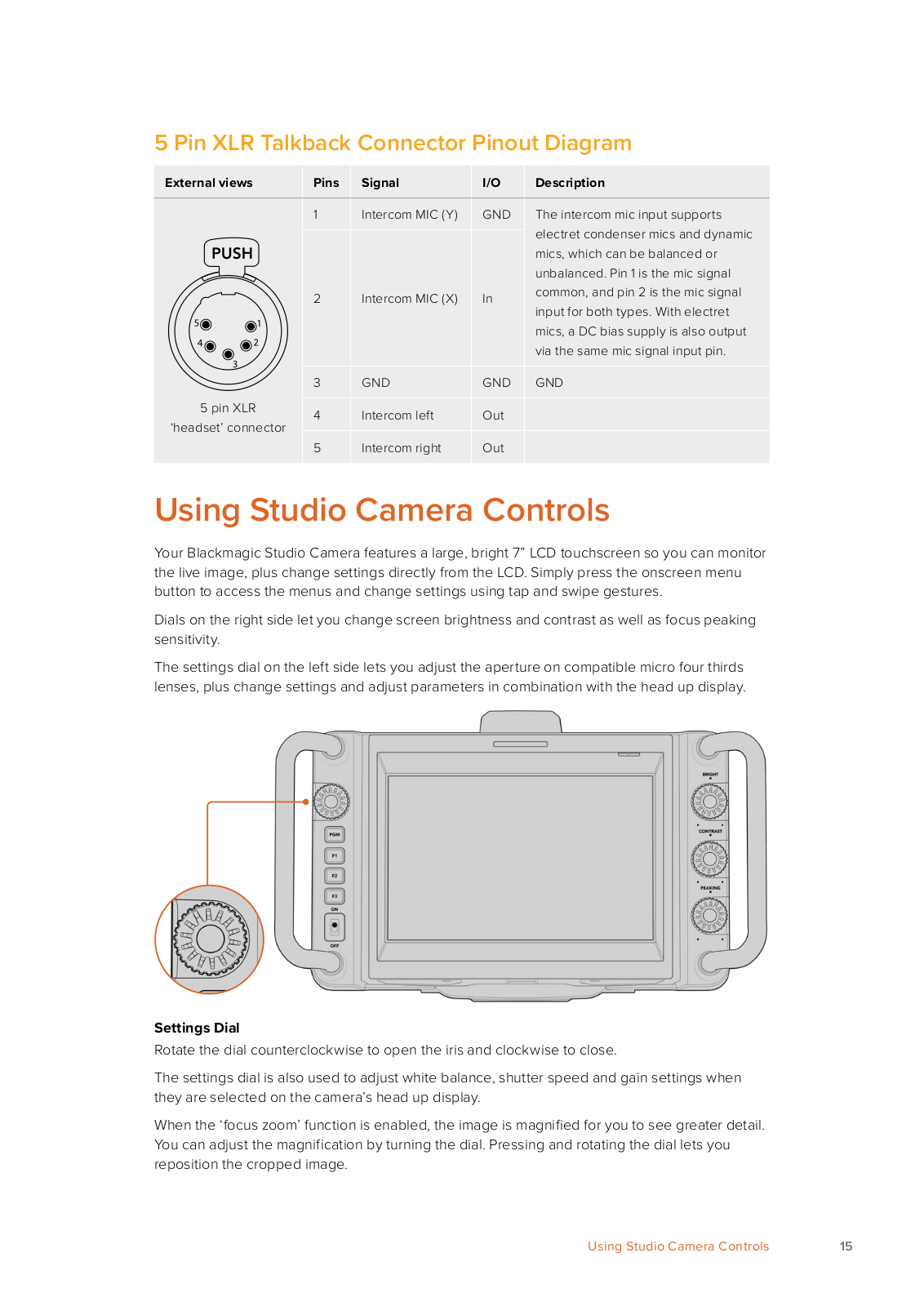
Your Blackmagic Studio Camera features a large, bright 7” LCD touchscreen so you can monitor the live image, plus change settings directly from the LCD. Simply press the onscreen menu button to access the menus and change settings using tap and swipe gestures.

Dials on the right side let you change screen brightness and contrast as well as focus peaking sensitivity.

The settings dial on the left side lets you adjust the aperture on compatible micro four thirds lenses, plus change settings and adjust parameters in combination with the head up display.

Settings Dial

Rotate the dial counterclockwise to open the iris and clockwise to close.

The settings dial is also used to adjust white balance, shutter speed and gain settings when they are selected on the camera’s head up display.

When the ‘focus zoom’ function is enabled, the image is magnified for you to see greater detail. You can adjust the magnification by turning the dial. Pressing and rotating the dial lets you reposition the cropped image.

Using Studio Camera Controls

15

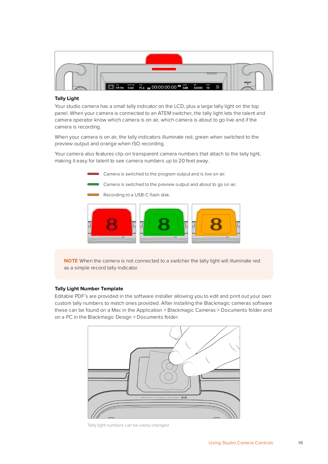
Tally Light

Your studio camera has a small tally indicator on the LCD, plus a large tally light on the top panel. When your camera is connected to an ATEM switcher, the tally light lets the talent and camera operator know which camera is on air, which camera is about to go live and if the camera is recording.

When your camera is on air, the tally indicators illuminate red, green when switched to the preview output and orange when ISO recording.

Your camera also features clip-on transparent camera numbers that attach to the tally light, making it easy for talent to see camera numbers up to 20 feet away.

Camera is switched to the program output and is live on air.

Camera is switched to the preview output and about to go on air.

Recording to a USB-C flash disk.

NOTE When the camera is not connected to a switcher the tally light will illuminate red as a simple record tally indicator.

Tally Light Number Template

Editable PDF’s are provided in the software installer allowing you to edit and print out your own custom tally numbers to match ones provided. After installing the Blackmagic cameras software these can be found on a Mac in the Application > Blackmagic Cameras > Documents folder and on a PC in the Blackmagic Design > Documents folder.

Tally light numbers can be easily changed

Using Studio Camera Controls

16

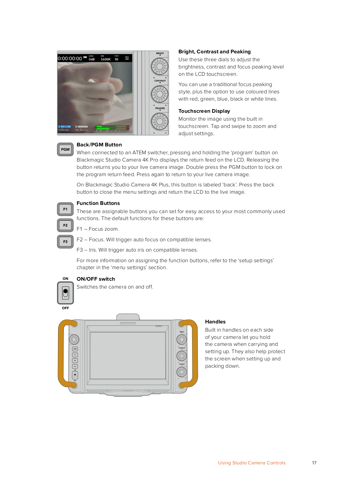
Bright, Contrast and Peaking

Use these three dials to adjust the brightness, contrast and focus peaking level on the LCD touchscreen.

You can use a traditional focus peaking style, plus the option to use coloured lines with red, green, blue, black or white lines.

Touchscreen Display

Monitor the image using the built in touchscreen. Tap and swipe to zoom and adjust settings.

Back/PGM Button

When connected to an ATEM switcher, pressing and holding the ‘program’ button on Blackmagic Studio Camera 4K Pro displays the return feed on the LCD. Releasing the button returns you to your live camera image. Double press the PGM button to lock on the program return feed. Press again to return to your live camera image.

On Blackmagic Studio Camera 4K Plus, this button is labeled ‘back’. Press the back button to close the menu settings and return the LCD to the live image.

Function Buttons

These are assignable buttons you can set for easy access to your most commonly used functions. The default functions for these buttons are:

F1 – Focus zoom.

F2 – Focus. Will trigger auto focus on compatible lenses. F3 – Iris. Will trigger auto iris on compatible lenses.

For more information on assigning the function buttons, refer to the ‘setup settings’ chapter in the ‘menu settings’ section.

ON/OFF switch

Switches the camera on and off.

Handles

Built in handles on each side of your camera let you hold the camera when carrying and

setting up. They also help protect the screen when setting up and packing down.

Using Studio Camera Controls

17

Touchscreen Controls

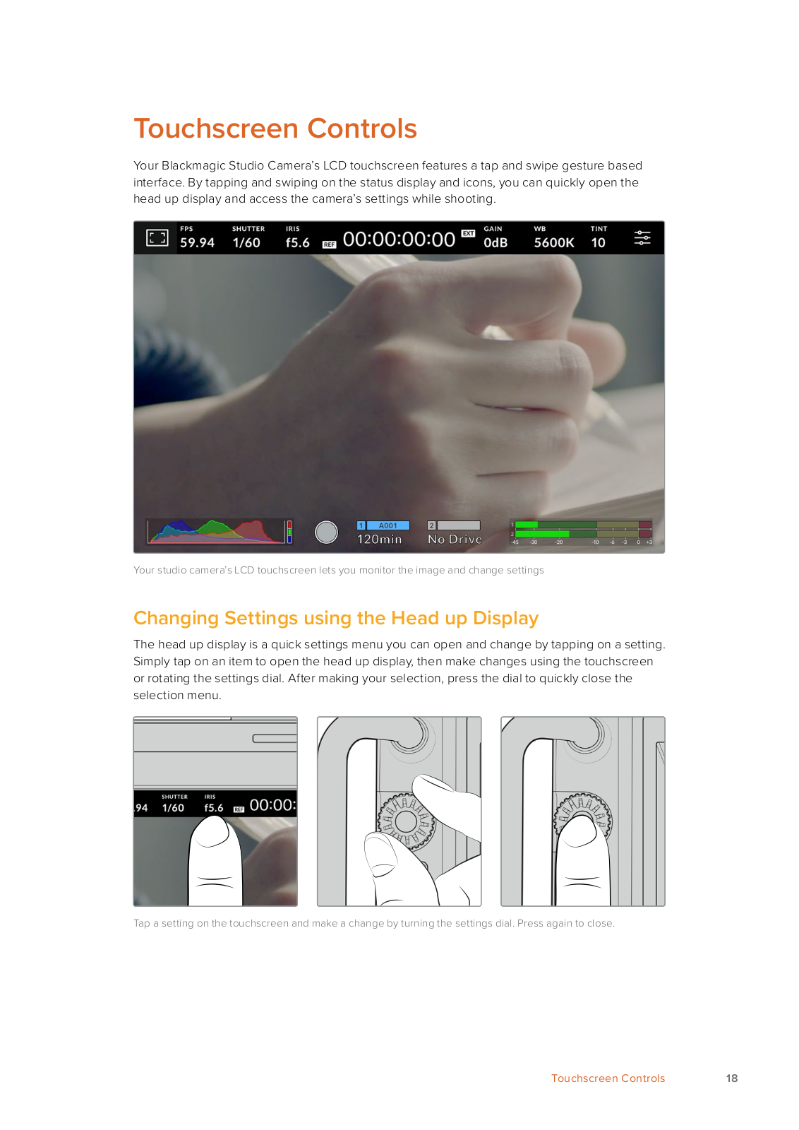
Your Blackmagic Studio Camera’s LCD touchscreen features a tap and swipe gesture based interface. By tapping and swiping on the status display and icons, you can quickly open the head up display and access the camera’s settings while shooting.

Your studio camera’s LCD touchscreen lets you monitor the image and change settings

Changing Settings using the Head up Display

The head up display is a quick settings menu you can open and change by tapping on a setting. Simply tap on an item to open the head up display, then make changes using the touchscreen or rotating the settings dial. After making your selection, press the dial to quickly close the selection menu.

Tap a setting on the touchscreen and make a change by turning the settings dial. Press again to close.

Touchscreen Controls

18

Head up Display Settings

This section of the manual describes the settings you can change using the head up display and settings dial.

LCD Monitor Options

Tap the ‘monitor’ icon at the top left of the touchscreen to access the LCD monitor settings. These settings let you toggle and adjust the appearance of your studio camera’s monitoring features, including zebra, focus assist, frame guides, grids, safe area guides and false color.

When accessing LCD monitor options, the controls for these features appear in a tabbed menu along the bottom edge of the LCD touchscreen.

Tap the icon at the top left of your camera’s LCD touchscreen to access LCD monitor options

Zebra

The ‘zebra’ setting toggles the appearance of the zebra on the LCD touchscreen, as well as setting the zebra level.

Zebra displays diagonal lines over areas of your image that exceed a set exposure level. For example, setting zebra to 100% shows which areas are completely overexposed. This is useful for achieving optimum exposure in fixed lighting conditions.

Tap the ‘zebra’ icon while accessing ‘LCD monitor options’ to access the zebra settings

To toggle the zebra for the LCD touchscreen, tap the switch icon in the bottom left of the screen while in the ‘zebra’ tab.

Set the exposure level at which the zebra appears by dragging the slider left and right, or tapping the arrow buttons next to the zebra level percentage. Zebra level is adjustable in five percent steps between 75 and 100 percent exposure.

For information on enabling zebra on your camera’s HDMI or SDI output, see the ‘monitor settings’ section in this manual.

TIP If you’re shooting in variable light such as outdoors on a partly overcast day, setting your zebra level lower than 100 can warn you of potential overexposure.

Focus Assist

The ‘focus assist’ setting toggles the appearance of focus assist on the LCD touchscreen, as well as setting the level of focus assistance.

Tap the ‘focus assist’ icon while accessing ‘LCD monitor options’ to access your camera’s focus assist settings

Touchscreen Controls

19

To toggle focus assistance for the LCD touchscreen, tap the switch icon in the bottom left of the screen while in the ‘focus assist’ tab. To set the level of focus assistance move the slider left and right along the bottom of the touchscreen.

The optimum level of focus assistance varies shot by shot. When focusing on actors, for example, higher level of focus assistance can help resolve edge detail in faces. A shot of foliage or brickwork, on the other hand, may show distracting amounts of focus information at higher settings.

For information on enabling focus assist on your camera’s HDMI output on both camera models and the SDI output on the Studio Camera 4K Pro, see the ‘monitor settings’ section in this manual.

TIP Your Blackmagic Studio Camera has two focus assist modes. You can switch between ‘peaking’ and ‘colored lines’ focus assistance in the ‘monitor’ settings menu. For more information, see the ‘monitor settings’ section in this manual.

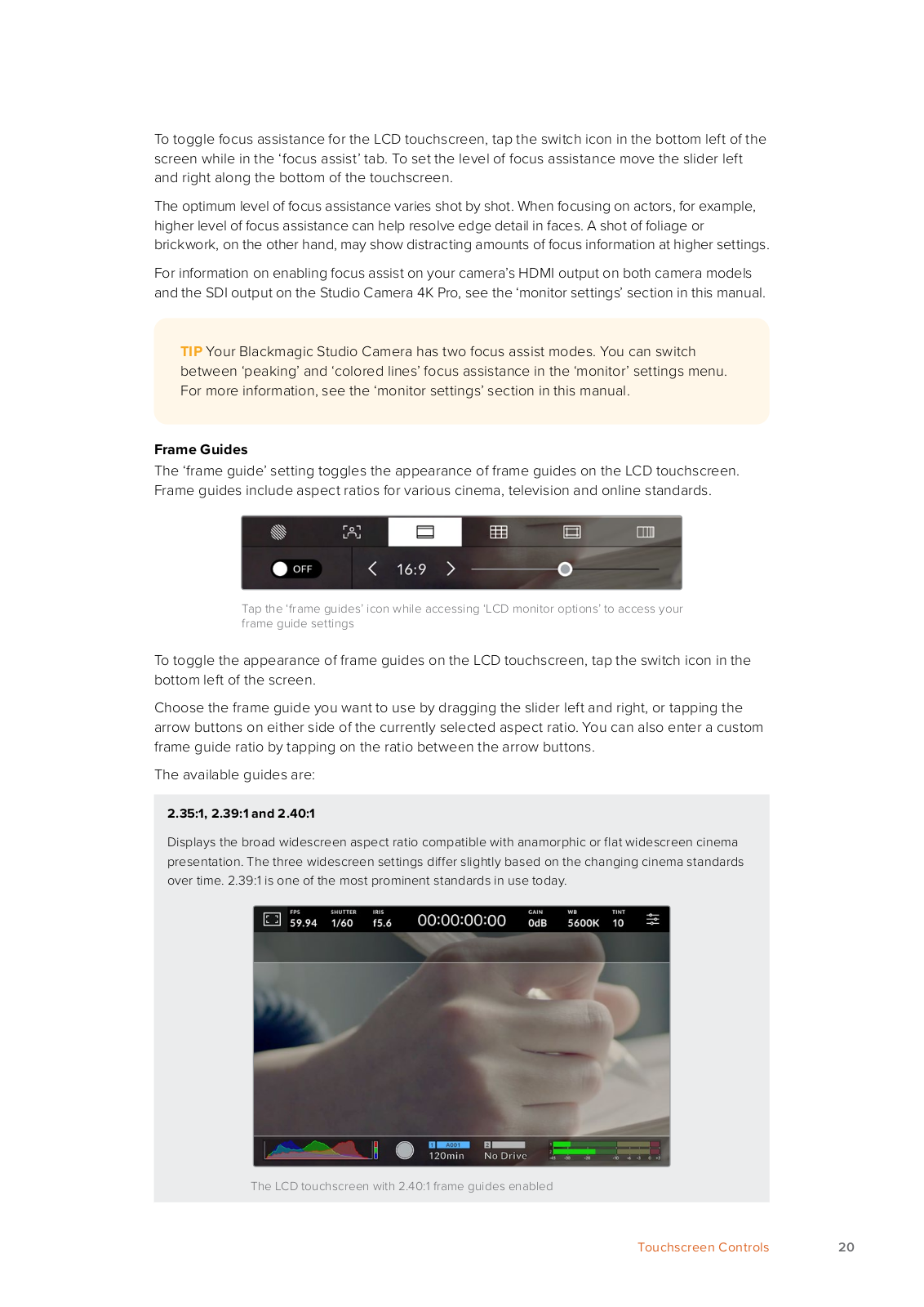
Frame Guides

The ‘frame guide’ setting toggles the appearance of frame guides on the LCD touchscreen. Frame guides include aspect ratios for various cinema, television and online standards.

Tap the ‘frame guides’ icon while accessing ‘LCD monitor options’ to access your frame guide settings

To toggle the appearance of frame guides on the LCD touchscreen, tap the switch icon in the bottom left of the screen.

Choose the frame guide you want to use by dragging the slider left and right, or tapping the arrow buttons on either side of the currently selected aspect ratio. You can also enter a custom frame guide ratio by tapping on the ratio between the arrow buttons.

The available guides are:

2.35:1, 2.39:1 and 2.40:1

Displays the broad widescreen aspect ratio compatible with anamorphic or flat widescreen cinema presentation. The three widescreen settings differ slightly based on the changing cinema standards over time. 2.39:1 is one of the most prominent standards in use today.

The LCD touchscreen with 2.40:1 frame guides enabled

Touchscreen Controls

20

2:1

Displays a ratio slightly wider than 16:9 but not as wide as 2.35:1.

1.85:1

Displays another common flat widescreen cinema aspect ratio. This ratio is slightly wider than HDTV 1.78:1 but not as wide as 2.39:1.

16:9

Displays a 1.78:1 aspect ratio compatible with 16:9 HD television and computer screens. This ratio is most commonly used for HD broadcasting and online videos. The same aspect ratio has also been adopted for Ultra HD broadcasting.

14:9

Displays a 14:9 aspect ratio used by some television broadcasters as a compromise between 16:9 and 4:3 television sets. Ideally, both 16:9 and 4:3 footage remains legible when center cropped to fit 14:9. You can use this as a compositional guide if you know your project may be broadcast by a television station that uses 14:9 cropping.

4:3

Displays the 4:3 aspect ratio compatible with SD television screens, or to help with framing when using 2x anamorphic adapters.

1:1

Displays a 1:1 ratio slightly narrower than 4:3. This square ratio is growing in popularity on social media.

4:5

Displays a 4:5 aspect ratio. This vertical aspect ratio is ideal for portraits and viewing on smartphones.

Custom Frame Guide Ratio

To create your own frame guide ratio for a unique appearance, tap on the ratio displayed between the arrow buttons. On the ‘custom frameguide’ screen tap the backspace button to delete the current ratio, then use the numeric keypad to specify a new ratio. Tap ‘update’ to apply your custom frame guide ratio and return to shooting.

Use the numeric keypad on the ‘custom frame guide’ screen to enter a new guide ratio

Touchscreen Controls

21

TIP You can change the opacity of frame guide overlays and enable or disable them on your camera’s HDMI or SDI output. For more information see the ‘monitor settings’ section of this manual.

Grids

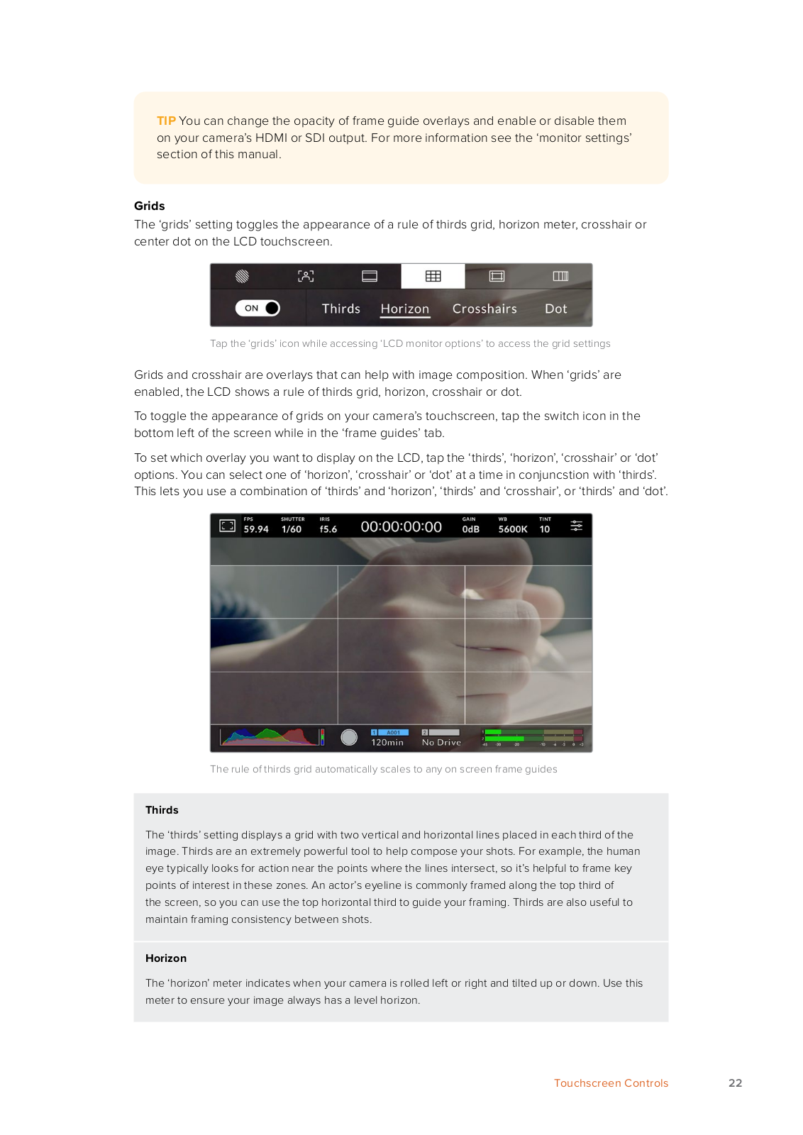
The ‘grids’ setting toggles the appearance of a rule of thirds grid, horizon meter, crosshair or center dot on the LCD touchscreen.

Tap the ‘grids’ icon while accessing ‘LCD monitor options’ to access the grid settings

Grids and crosshair are overlays that can help with image composition. When ‘grids’ are enabled, the LCD shows a rule of thirds grid, horizon, crosshair or dot.

To toggle the appearance of grids on your camera’s touchscreen, tap the switch icon in the bottom left of the screen while in the ‘frame guides’ tab.

To set which overlay you want to display on the LCD, tap the ‘thirds’, ‘horizon’, ‘crosshair’ or ‘dot’ options. You can select one of ‘horizon’, ‘crosshair’ or ‘dot’ at a time in conjuncstion with ‘thirds’. This lets you use a combination of ‘thirds’ and ‘horizon’, ‘thirds’ and ‘crosshair’, or ‘thirds’ and ‘dot’.

The rule of thirds grid automatically scales to any on screen frame guides

Thirds

The ‘thirds’ setting displays a grid with two vertical and horizontal lines placed in each third of the image. Thirds are an extremely powerful tool to help compose your shots. For example, the human eye typically looks for action near the points where the lines intersect, so it’s helpful to frame key points of interest in these zones. An actor’s eyeline is commonly framed along the top third of

the screen, so you can use the top horizontal third to guide your framing. Thirds are also useful to maintain framing consistency between shots.

Horizon

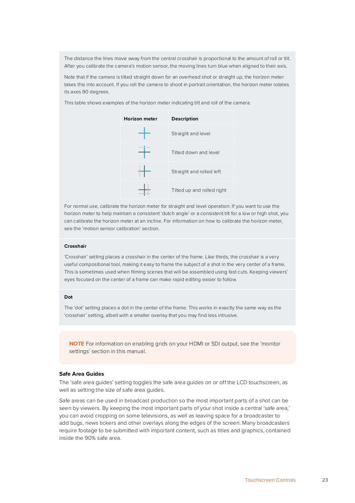
The ‘horizon’ meter indicates when your camera is rolled left or right and tilted up or down. Use this meter to ensure your image always has a level horizon.

Touchscreen Controls

22

The distance the lines move away from the central crosshair is proportional to the amount of roll or tilt. After you calibrate the camera’s motion sensor, the moving lines turn blue when aligned to their axis.

Note that if the camera is tilted straight down for an overhead shot or straight up, the horizon meter takes this into account. If you roll the camera to shoot in portrait orientation, the horizon meter rotates its axes 90 degrees.

This table shows examples of the horizon meter indicating tilt and roll of the camera.

Horizon meter

Description


Straight and level


Tilted down and level


Straight and rolled left


Tilted up and rolled right


For normal use, calibrate the horizon meter for straight and level operation. If you want to use the horizon meter to help maintain a consistent ‘dutch angle’ or a consistent tilt for a low or high shot, you can calibrate the horizon meter at an incline. For information on how to calibrate the horizon meter, see the ‘motion sensor calibration’ section.

Crosshair

‘Crosshair’ setting places a crosshair in the center of the frame. Like thirds, the crosshair is a very useful compositional tool, making it easy to frame the subject of a shot in the very center of a frame. This is sometimes used when filming scenes that will be assembled using fast cuts. Keeping viewers’ eyes focused on the center of a frame can make rapid editing easier to follow.

Dot

The ‘dot’ setting places a dot in the center of the frame. This works in exactly the same way as the ‘crosshair’ setting, albeit with a smaller overlay that you may find less intrusive.

NOTE For information on enabling grids on your HDMI or SDI output, see the ‘monitor settings’ section in this manual.

Safe Area Guides

The ‘safe area guides’ setting toggles the safe area guides on or off the LCD touchscreen, as well as setting the size of safe area guides.

Safe areas can be used in broadcast production so the most important parts of a shot can be seen by viewers. By keeping the most important parts of your shot inside a central ‘safe area,’ you can avoid cropping on some televisions, as well as leaving space for a broadcaster to add bugs, news tickers and other overlays along the edges of the screen. Many broadcasters require footage to be submitted with important content, such as titles and graphics, contained inside the 90% safe area.

Touchscreen Controls

23

Safe area guides can also be used to assist with framing your shot where you know that the shot will be stabilised in post production, which can crop the edges of the image. They can also be used to indicate a specific crop. For example by setting it to 50% when recording at Ultra HD 3840x2160 you can see what a 1920x1080 crop of the frame would look like. The safe area guides also scale to your frame guides, so they will adjust to indicate the chosen percentage of your target frame.

The ‘safe area’ indicator set to 85%

To toggle safe area guides for the LCD touchscreen, tap the switch icon in the bottom left of the screen while in the ‘safe area guides’ tab. To set the level of safe area guides for your camera’s LCD touchscreen, tap the left or right arrows on either side of the current numerical value at the bottom of the touchscreen. Alternatively, you can drag the slider left or right.

For information on enabling safe area guides on your camera’s HDMI or SDI output, see the ‘monitor settings’ section in this manual.

False Color

The ‘false color’ setting toggles the appearance of false color exposure assistance on the LCD touchscreen.

False color overlays different colors onto your image that represent exposure values for different elements in your image. For example, pink represents optimum exposure for lighter skin tones, while green is a good match to darker skin tones. By monitoring the pink or green false color when recording people, you can maintain consistent exposure for their skin tones.

Similarly, when elements in your image change from yellow to red, that means they are now over exposed.

False Color Chart

Touchscreen Controls

24

To toggle false color for the LCD touchscreen, tap the switch icon in the bottom left of the screen while in the ‘false color’ tab.

The ‘false color’ exposure assistance tab

Frames Per Second

The ‘FPS’ indicator displays your currently selected frames per second.

Tap the frames per second indicator to access frame rate settings

Tapping the ‘FPS’ indicator lets you change your camera’s sensor and project frame rates via a menu at the bottom of the LCD touchscreen.

Project Frame Rate

The project frame rate is the camera’s recording format frame rate and provides a selection of common frame rates used in the film and television industry. This frame rate should normally be set to match your broadcast delivery format.

8 project frame rates are available including 23.98, 24, 25, 29.97, 30, 50, 59.94 and 60 frames per second.

To adjust your camera’s project frame rate while in the ‘FPS’ menu, tap the left or right arrows next to the current frame rate at the bottom left of your touchscreen. Alternatively, you can drag the slider left or right.

Tap the arrows on either side of the project frame rate or move the slider to make adjustments

Sensor Frame Rate

The sensor frame rate sets how many actual frames from the sensor are recorded every second. This frame rate will affect how fast or slow your recorded video will play back at your set project frame rate in DaVinci Resolve.

With ‘off speed frame rate’ enabled, tap a preset or the arrows on either side of the sensor frame rate or move the slider to make adjustments

Touchscreen Controls

25

By default, the project and sensor frame rates are matched for a natural playback speed. However, by tapping the ‘off speed frame rate’ switch icon in the bottom right hand side of your camera’s ‘FPS’ menu, you can independently set the sensor frame rate.

To change the sensor frame rate, tap the arrows next to the sensor frame rate indicator in the lower left of your touchscreen. You can also drag the slider left or right to increase or decrease the frame rate. Above the slider, you can tap on a common off speed frame rate. These are based on your current project frame rate.

You can create dynamic and interesting speed effects in DaVinci Resolve by varying the sensor frame rate for your recorded video. Setting the sensor frame rate higher than your project frame rate will create slow motion during playback.

Shutter

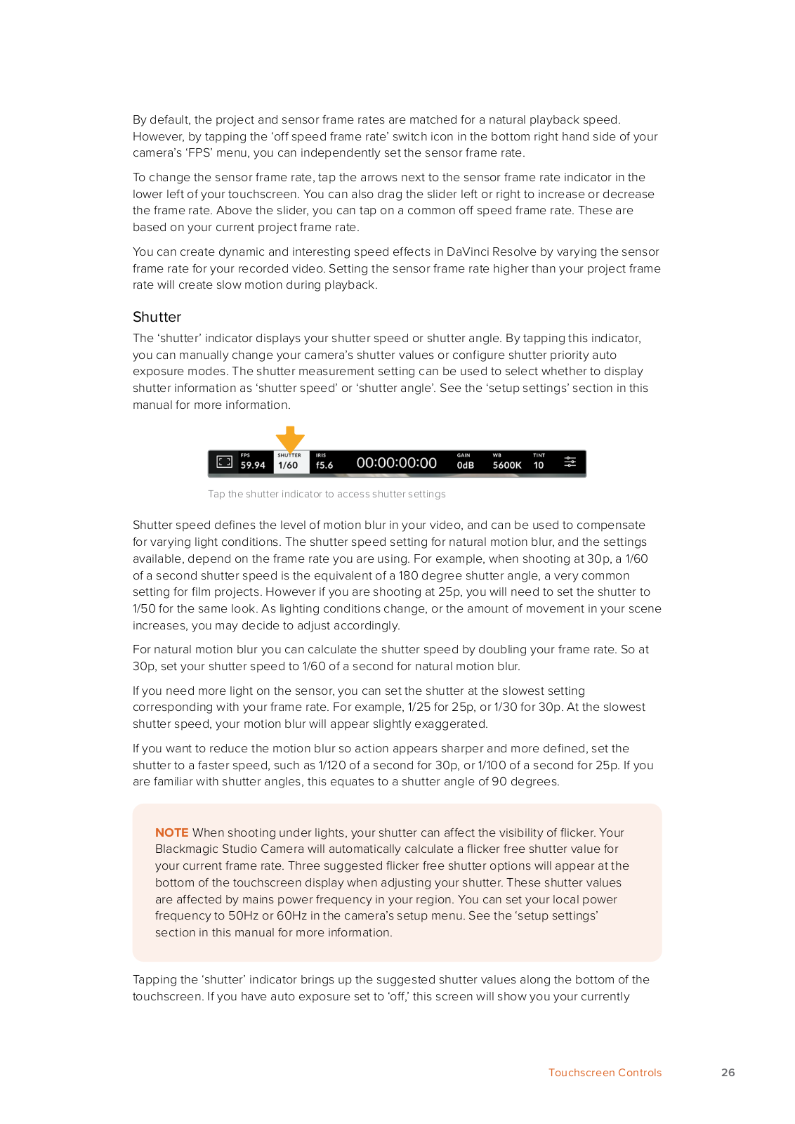
The ‘shutter’ indicator displays your shutter speed or shutter angle. By tapping this indicator, you can manually change your camera’s shutter values or configure shutter priority auto exposure modes. The shutter measurement setting can be used to select whether to display shutter information as ‘shutter speed’ or ‘shutter angle’. See the ‘setup settings’ section in this manual for more information.

Tap the shutter indicator to access shutter settings

Shutter speed defines the level of motion blur in your video, and can be used to compensate for varying light conditions. The shutter speed setting for natural motion blur, and the settings available, depend on the frame rate you are using. For example, when shooting at 30p, a 1/60 of a second shutter speed is the equivalent of a 180 degree shutter angle, a very common setting for film projects. However if you are shooting at 25p, you will need to set the shutter to 1/50 for the same look. As lighting conditions change, or the amount of movement in your scene increases, you may decide to adjust accordingly.

For natural motion blur you can calculate the shutter speed by doubling your frame rate. So at 30p, set your shutter speed to 1/60 of a second for natural motion blur.

If you need more light on the sensor, you can set the shutter at the slowest setting corresponding with your frame rate. For example, 1/25 for 25p, or 1/30 for 30p. At the slowest shutter speed, your motion blur will appear slightly exaggerated.

If you want to reduce the motion blur so action appears sharper and more defined, set the shutter to a faster speed, such as 1/120 of a second for 30p, or 1/100 of a second for 25p. If you are familiar with shutter angles, this equates to a shutter angle of 90 degrees.

NOTE When shooting under lights, your shutter can affect the visibility of flicker. Your Blackmagic Studio Camera will automatically calculate a flicker free shutter value for your current frame rate. Three suggested flicker free shutter options will appear at the bottom of the touchscreen display when adjusting your shutter. These shutter values are affected by mains power frequency in your region. You can set your local power frequency to 50Hz or 60Hz in the camera’s setup menu. See the ‘setup settings’ section in this manual for more information.

Tapping the ‘shutter’ indicator brings up the suggested shutter values along the bottom of the touchscreen. If you have auto exposure set to ‘off,’ this screen will show you your currently

Touchscreen Controls

26

selected shutter value, as well as the available flicker free shutter values, based on the mains power frequency you have selected in your camera’s setup menu. The characteristics of individual light sources may still cause flicker even when using flicker free values. We recommend always performing a test shoot when not using continuous lights. For more information, see the ‘setup settings’ section in this manual.

To select one of the flicker free shutter values, simply tap on one of the displayed shutter values. Using the arrows on either side of the current shutter value indicator, will cycle through some of the most commonly used values.

Your camera will suggest flicker free shutter values based on the mains power frequency you choose in the ‘setup’ menu

If you would like to choose a specific shutter value, you can do so by double tapping the current shutter indicator at the bottom left of your screen. This will bring up a keypad that allows you to type in any shutter value you wish.

If you type in a shutter value that is less than your current frame rate, for example 1/25th when shooting at 29.97 frames per second, the nearest achievable shutter value will be used. The nearest shutter speed in this example would be 1/30th.

Use the manual shutter keypad to enter your shutter timing of choice when shooting outdoors or under flicker free lights

Tapping the ‘auto exposure’ switch icon at the far right of the shutter menu opens the shutter auto exposure menu.

This gives you the following auto exposure options.

Shutter

This setting automatically adjusts shutter value to maintain a constant exposure while keeping iris aperture consistent. If you want to maintain a fixed depth of field, this is the setting to choose. It’s worth mentioning that the subtle automatic adjustments of the shutter may have an effect on motion blur. It’s also worth keeping an eye out for any flicker that may be introduced from various light fixtures on indoor shoots. The auto iris feature is not available when the ‘shutter’ auto exposure mode is selected.

Touchscreen Controls

27

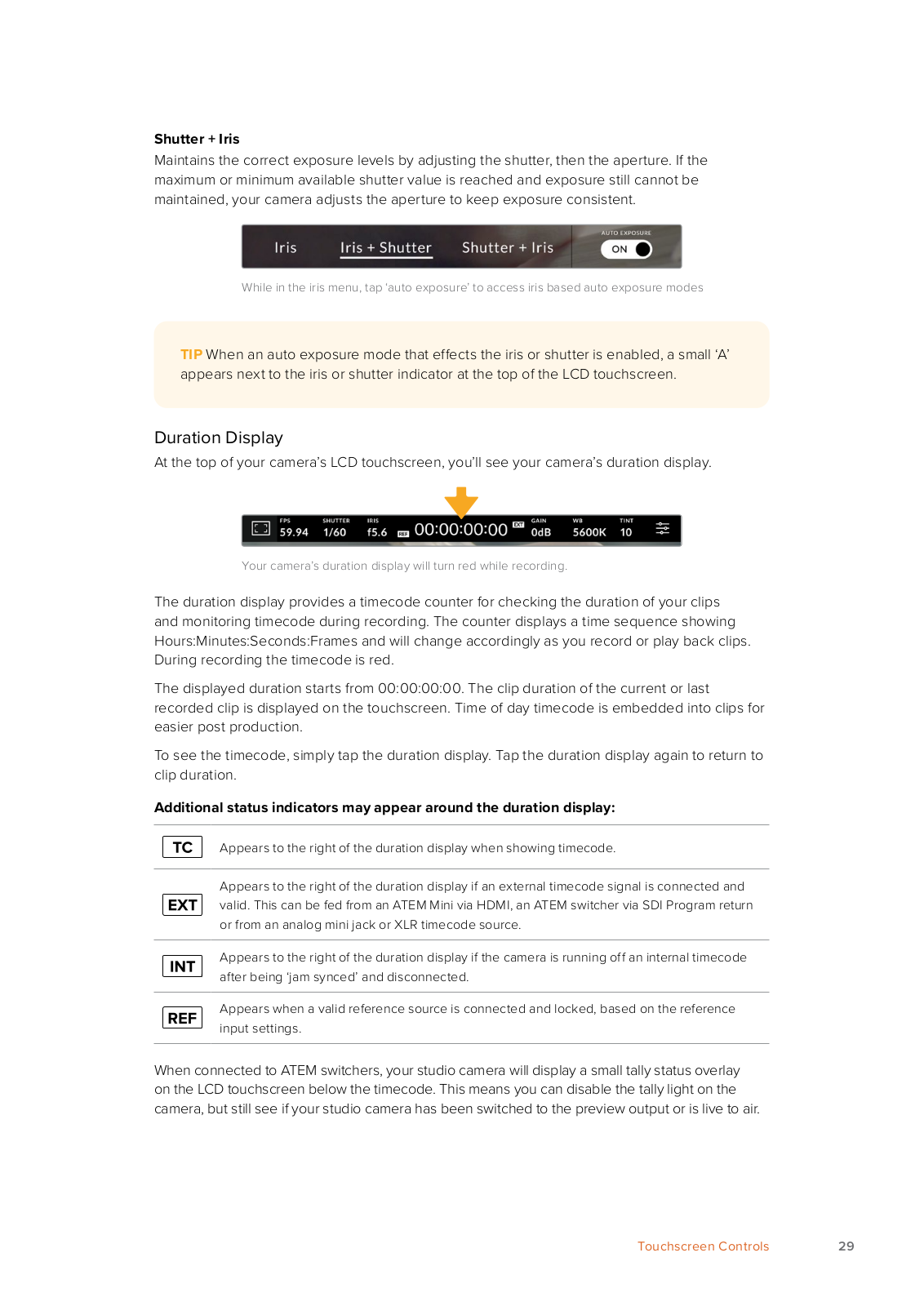
Shutter + Iris

Maintains the correct exposure levels by adjusting the shutter, then the aperture. If the maximum or minimum available shutter value is reached and exposure still cannot be maintained, your camera adjusts the aperture to keep exposure consistent.

Iris + Shutter

Maintains the correct exposure levels by adjusting the aperture, then the shutter value. If the maximum or minimum available aperture is reached and exposure still cannot be maintained, your camera adjusts the shutter value to keep exposure consistent.

While in the shutter menu, tap ‘auto exposure’ to access shutter based auto exposure modes

TIP When an auto exposure mode that effects the shutter or iris is enabled, a small ‘A’ appears next to the shutter or iris indicator at the top of the LCD touchscreen.

Iris

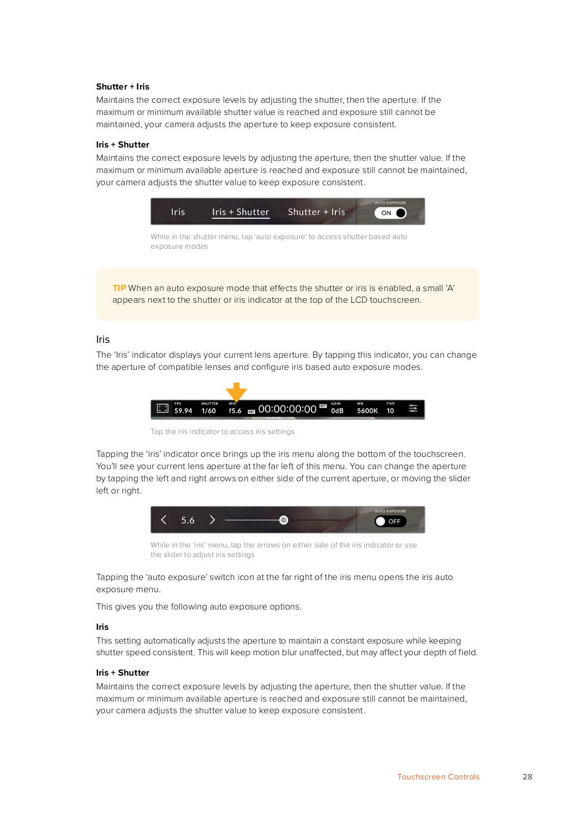
The ‘Iris’ indicator displays your current lens aperture. By tapping this indicator, you can change the aperture of compatible lenses and configure iris based auto exposure modes.

Tap the iris indicator to access iris settings

Tapping the ‘iris’ indicator once brings up the iris menu along the bottom of the touchscreen. You’ll see your current lens aperture at the far left of this menu. You can change the aperture by tapping the left and right arrows on either side of the current aperture, or moving the slider left or right.

While in the ‘iris’ menu, tap the arrows on either side of the iris indicator or use the slider to adjust iris settings

Tapping the ‘auto exposure’ switch icon at the far right of the iris menu opens the iris auto exposure menu.

This gives you the following auto exposure options.

Iris

This setting automatically adjusts the aperture to maintain a constant exposure while keeping shutter speed consistent. This will keep motion blur unaffected, but may affect your depth of field.

Iris + Shutter

Maintains the correct exposure levels by adjusting the aperture, then the shutter value. If the maximum or minimum available aperture is reached and exposure still cannot be maintained, your camera adjusts the shutter value to keep exposure consistent.

Touchscreen Controls

28

Shutter + Iris

Maintains the correct exposure levels by adjusting the shutter, then the aperture. If the maximum or minimum available shutter value is reached and exposure still cannot be maintained, your camera adjusts the aperture to keep exposure consistent.

While in the iris menu, tap ‘auto exposure’ to access iris based auto exposure modes

TIP When an auto exposure mode that effects the iris or shutter is enabled, a small ‘A’ appears next to the iris or shutter indicator at the top of the LCD touchscreen.

Duration Display

At the top of your camera’s LCD touchscreen, you’ll see your camera’s duration display.

Your camera’s duration display will turn red while recording.

The duration display provides a timecode counter for checking the duration of your clips and monitoring timecode during recording. The counter displays a time sequence showing Hours:Minutes:Seconds:Frames and will change accordingly as you record or play back clips. During recording the timecode is red.

The displayed duration starts from 00:00:00:00. The clip duration of the current or last recorded clip is displayed on the touchscreen. Time of day timecode is embedded into clips for easier post production.

To see the timecode, simply tap the duration display. Tap the duration display again to return to clip duration.

Additional status indicators may appear around the duration display:

Appears to the right of the duration display when showing timecode.

Appears to the right of the duration display if an external timecode signal is connected and valid. This can be fed from an ATEM Mini via HDMI, an ATEM switcher via SDI Program return or from an analog mini jack or XLR timecode source.

Appears to the right of the duration display if the camera is running off an internal timecode after being ‘jam synced’ and disconnected.

Appears when a valid reference source is connected and locked, based on the reference input settings.

When connected to ATEM switchers, your studio camera will display a small tally status overlay on the LCD touchscreen below the timecode. This means you can disable the tally light on the camera, but still see if your studio camera has been switched to the preview output or is live to air.

Touchscreen Controls

29

ATEM switchers automatically synchronize the timecode on your studio camera to match the switcher’s timecode when connected. This makes it easier to perform accurate multi camera edits in DaVinci Resolve.

Gain

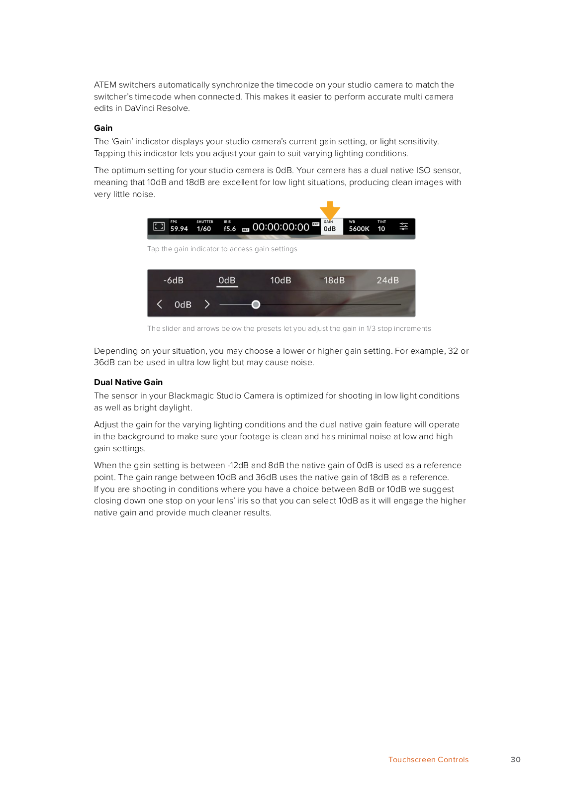
The ‘Gain’ indicator displays your studio camera’s current gain setting, or light sensitivity. Tapping this indicator lets you adjust your gain to suit varying lighting conditions.

The optimum setting for your studio camera is 0dB. Your camera has a dual native ISO sensor, meaning that 10dB and 18dB are excellent for low light situations, producing clean images with very little noise.

Tap the gain indicator to access gain settings

The slider and arrows below the presets let you adjust the gain in 1/3 stop increments

Depending on your situation, you may choose a lower or higher gain setting. For example, 32 or 36dB can be used in ultra low light but may cause noise.

Dual Native Gain

The sensor in your Blackmagic Studio Camera is optimized for shooting in low light conditions as well as bright daylight.

Adjust the gain for the varying lighting conditions and the dual native gain feature will operate in the background to make sure your footage is clean and has minimal noise at low and high gain settings.

When the gain setting is between -12dB and 8dB the native gain of 0dB is used as a reference point. The gain range between 10dB and 36dB uses the native gain of 18dB as a reference.

If you are shooting in conditions where you have a choice between 8dB or 10dB we suggest closing down one stop on your lens’ iris so that you can select 10dB as it will engage the higher native gain and provide much cleaner results.

Touchscreen Controls

30

Loading...
+ 1093 hidden pages