

Page 1
Installation and Operation Manual
Blackmagic Studio Cameras
English, 日本語, Français, Deutsch, Español, 中文, 한국어 and Русский
Mac OS X
Windows
September 2015
™
™
Page 2
Blackmagic Studio Camera
English 3
日本語
Français 86
Deutsch 128
Español 170
中文
한국어
Русский
44
212
254
296
Page 3
3
Welcome
Thank you for purchasing a Blackmagic Studio Camera!
We are extremely excited to have designed the Blackmagic Studio Camera
and Micro Studio Camera 4K. Ever since I was a teenager I have loved live
production, it’s so exciting!
Traditionally cameras with talkback and tally were very expensive and physically
large, so hard to manage. We really wanted to solve this problem by designing
a more compact camera that included all the talkback, tally and camera control
features of physically much larger cameras.
That’s why the Blackmagic Studio Camera was developed. We wanted to build
a much smaller camera for portability, however normally small cameras have
small tiny screens. We did not want that. What we really wanted was a much
larger viewfinder! The result is Blackmagic Studio Camera, a small broadcast
camera with a very large viewfinder that’s wonderful to use! Precise focus and
framing are so easy with a viewfinder this large!
Of course you get tally indicators, talkback, massive built in battery and of
course a fantastic quality camera with flexible MFT lens mount. It’s everything
you need in a complete package! You can plug in larger wind protected
microphones even with phantom power and with user installable optical fiber,
you can add an SFP module when you need to run your camera miles away
from your switcher! If you need, you can even add a HyperDeck Shuttle and
use the camera for general production use!
Blackmagic Micro Studio Camera 4K takes the small size and capability of
Blackmagic Studio Camera even further! This tiny camera pairs an amazing
Ultra HD sensor with an incredibly tiny chassis and a host of remote control
options. Now you can capture broadcast production footage from previously
impossible locations, all with complete control from an ATEM switcher or via
custom remote.
We hope you use your new camera for some amazing live productions and
produce some fantastic looking work! We are extremely excited to see what
creative work you produce!
Grant Petty
CEO Blackmagic Design
Page 4
Contents
4
Blackmagic Studio Camera
5 Getting Started
Attaching a Lens 5
Turning Your Camera On 5
6 Camera Features
Blackmagic Studio Camera Features 6
Blackmagic Micro Studio Camera 4K Features 8
10 Camera Connections
Blackmagic Studio Camera - Left Side 10
Blackmagic Studio Camera - Right Side 11
Blackmagic Micro Studio Camera 4K - Left Side 12
Blackmagic Micro Studio Camera 4K - Right Side 13
14 Customization
Blackmagic Micro Studio Camera 4K Expansion Cable 14
Wiring diagram for the Blackmagic Micro Studio
Camera Expansion Cable 15
16 Camera Settings
Camera Settings 16
Audio Settings 18
Monitoring Settings 20
Studio Settings 21
Remote Settings 22
Button Settings 22
24 Camera Video Output
Connecting to Video Switchers 24
Connecting to Recorders 24
25 Blackmagic Camera Setup
26 Attaching Accessories
Sun Shade 26
Other Accessories 26
27 Using ATEM Software Control
Introducing Camera Control 27
Using Camera Control 28
DaVinci Resolve Primary Color Corrector 30
Synchronizing Settings 32
33 Developer Information
Blackmagic Video Device Embedded Control Protocol 33
42 Help
43 Warranty
Page 5
55 Getting Started
OPTICAL OUT
OPTICAL IN
SDI OUT
SDI IN
REF
12V
1
1
3
2
PUSH
2
1
3
2
PUSH
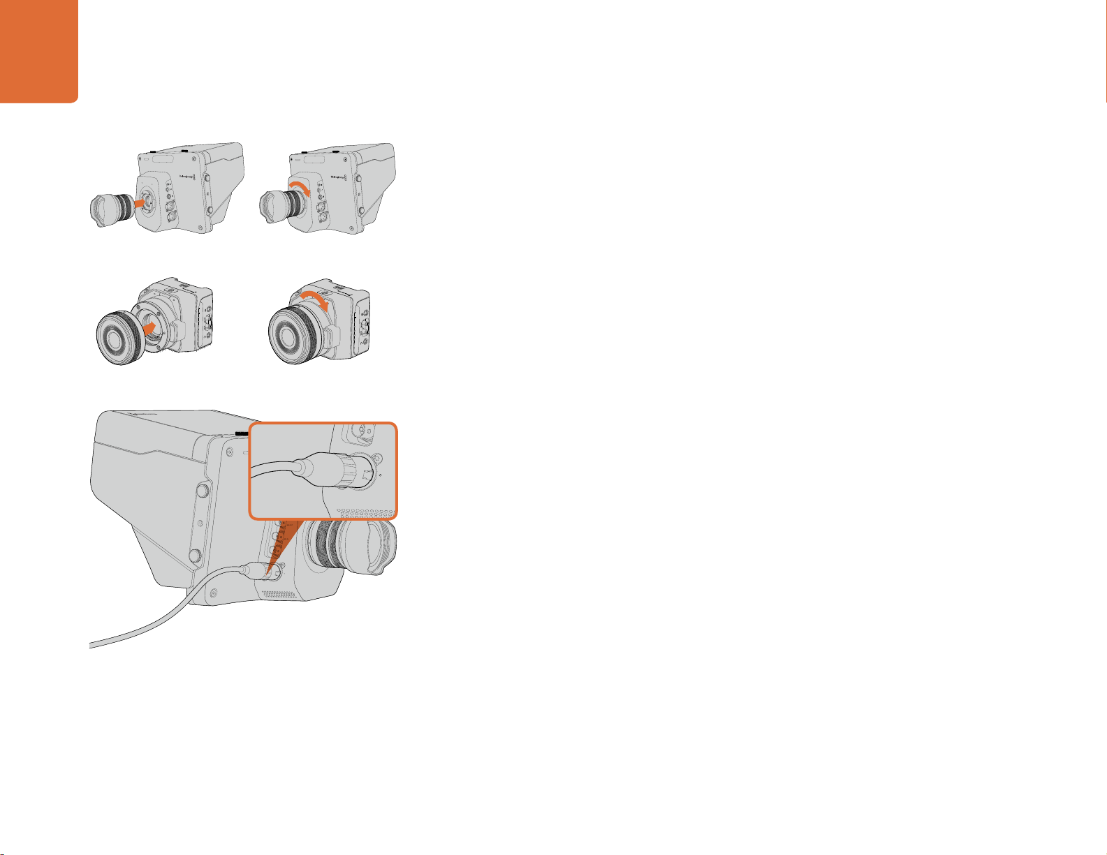
Attaching and removing a lens on Studio Camera.
Attaching and removing a lens on Micro Studio Camera 4K.
Getting Started
Attaching a Lens
Getting started with your Blackmagic Studio Camera or Blackmagic Micro Studio Camera 4K is as
1
1
3
2
PUSH
2
1
3
2
PUSH
simple as attaching a lens and turning the camera on. To remove the protective dust cap from the
lens mount, hold down the locking button and rotate the cap counterclockwise until it is released.
We recommend you always turning off your Blackmagic camera prior to attaching or removing a lens.
To attach a lens:
Step 1. Align the dot on your lens with the dot on the camera mount. Many lenses have either a blue,
red or white dot or some other indicator.
Step 2. Twist the lens clockwise until it locks into place.
Step 3. To remove the lens, hold down the locking button, rotate the lens counterclockwise until
its dot or indicator reaches the 12 o’clock position and gently remove.
When no lens is attached to the camera, the lens mount is exposed to dust and other debris so you'll
want to keep the dust cap on whenever possible.
OPTICAL OUT
OPTICAL IN
SDI OUT
SDI IN
REF
12V
Use the supplied power adapter to charge the internal battery
and power the Studio Camera.
Turning Your Camera On
The Studio Camera has an internal battery that can be charged using the supplied power adapter.
The camera can be charged and operated while connected via external power and will switch between
power sources without any interruption.
Step 1. Press the power button below the LCD. The live camera image will appear on the LCD.
Step 2. Press and hold the power button to switch off the camera.
Micro Studio Camera 4K accepts LP-E6 and LP-E6N batteries, which can be charged with an external
battery charger or slowly trickle charged by the camera. The camera can also be charged and
operated via external power and will switch between power sources automatically if external power
is interrupted. External power is provided via the Micro Studio Camera 4K's expansion port.
Step 1. Press the power button on the right hand side of the camera.
The tally light will glow white to indicate the camera is on.
Step 2. Press and hold the power button to switch off your camera.
That's all there is to getting started. You can now connect your camera to a switcher, or ATEM
Converter, and start creating your live production!
Page 6
66 Camera Features
FOCUS
IRIS PTT PGM LUT SET DISPLAY MENU
1
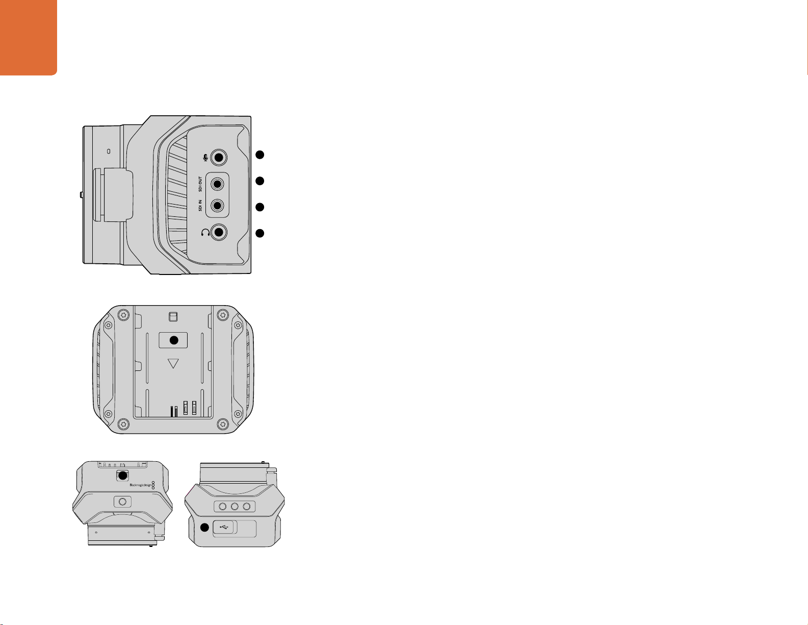
Blackmagic Studio Camera Features
Front Panel
1. Front Tally Light
Indicates to the on-air talent which camera is currently "live". See the 'monitoring settings' section in this
manual for more details.
Left Panel
2. LANC Remote
2.5mm stereo jack for LANC remote control supports iris, zoom and focus control.
3. Aviation Headphones
0.25" TRS connector for monitoring PGM and control room audio with aviation style headsets.
4. Headphones Microphone Input
0.206" TRS connector for talking to the control room with aviation style headsets.
5. Audio Inputs
L OUT
2
3
4
1
PUSH
5
2
PUSH
OPTICA
6
OPTICAL IN
7
SDI OUT
SDI IN
8
REF
9
10
12V
2 x 1/4" balanced XLR connectors for audio input.
6. Optical Input/Output
Optical input and output allows cable runs of up to 28 miles.
Refer to the 'Blackmagic Studio Camera - left panel' section in this manual for more details.
Right Panel
7. SDI Out
SDI output for connecting to a switcher or other device.
8. SDI In
SDI input allows the camera operator to view the Program (PGM) output.
9. Reference Input
Allows multiple cameras to be genlocked to a blackburst or tri-level reference signal.
10. Power
12 – 24V power input for power supply and battery charging.
Refer to the 'Blackmagic Studio Camera - right panel' section in this manual for more details.
Page 7
77 Camera Features
1
PUSH
2
PUSH
11 12
Rear Panel
11. 10" LCD
Monitor live camera output or program output, or view the menu. See the 'monitoring section' in
this manual for more details.
12. Rear Tally Light
When lit, it indicates to the camera operator that their camera is currently live.
13. Focus Button
Press once to auto focus or twice to display focus peaking on the LCD.
FOCUS
IRIS PTT PGM LUT SET DISPLAY MENU
14. Iris Button
Press once for auto exposure.
13 14 15 16 17 18
19
22
212018
15. Push To Talk Button (PTT)
Press and HOLD to talk. Press twice in quick succession for hands free communication. Press again
to revert to the default behavior.
16. Program (PGM) Button
Press to toggle between live camera output and program output from a switcher control room.
23
17. Look Up Table (LUT) Button
Currently not implemented.
18. Menu Navigation Buttons
Navigate the menu on the LCD.
19. Set Button
Use this button to confirm your menu selections.
20. Display Button
Press this button to toggle overlays on and off.
21. Menu Button
Access the menu on the LCD.
22. Power Button
Press the power button to turn on the Blackmagic Studio Camera. Press and hold the button to turn
the camera off.
Refer to the 'button settings' section in this manual for more details.
Bottom Panel
23. USB Connector
USB Mini-B port for camera firmware updates. See 'Blackmagic Camera Setup' section in this manual.
Page 8
88 Camera Features
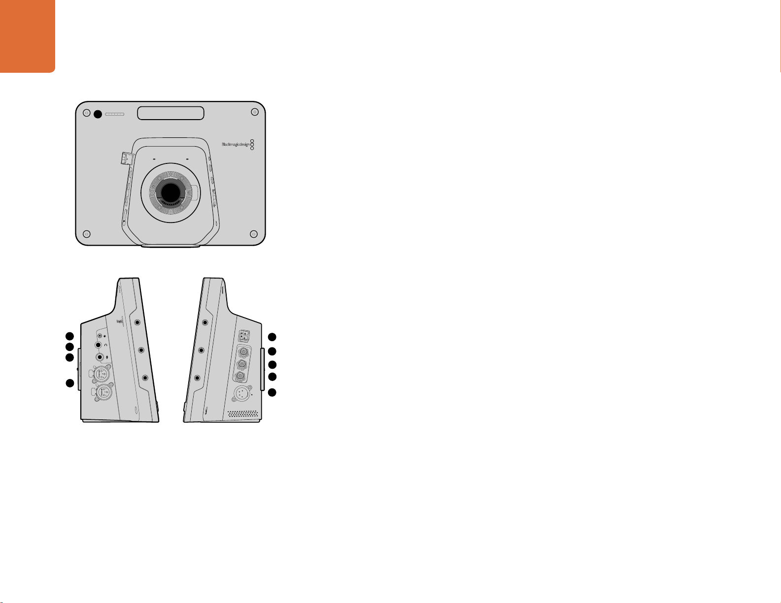
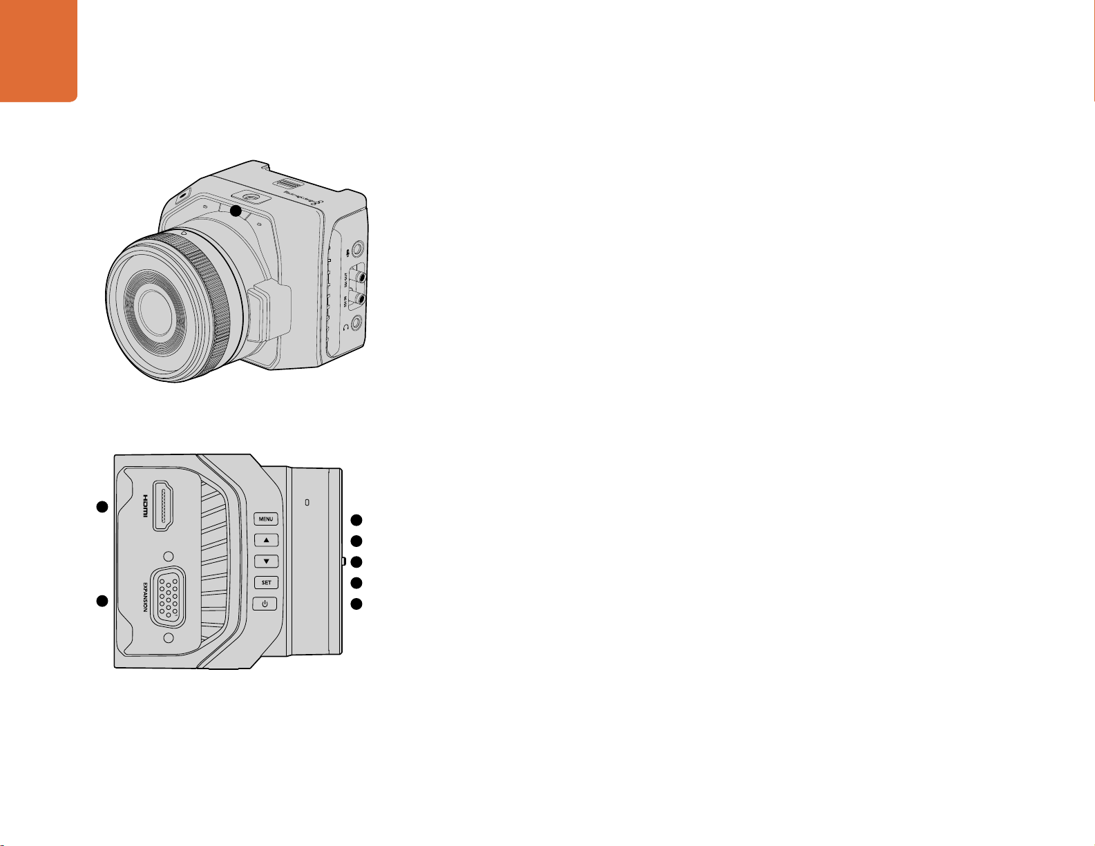
Blackmagic Micro Studio Camera 4K Features
Front Panel
1
1. Tally Light
The Tally light indicates to on-air talent which camera is currently 'live,' as well as alerting the operator
to the status of the camera. The following scenarios are possible:
White - Powered
Red - Live
Alternating red and orange - Battery low when live
Alternating white and orange - Battery low
You can adjust the brightness of the tally light in Micro Studio Camera 4K's settings. See the 'camera
settings' section for more information.
Left Panel
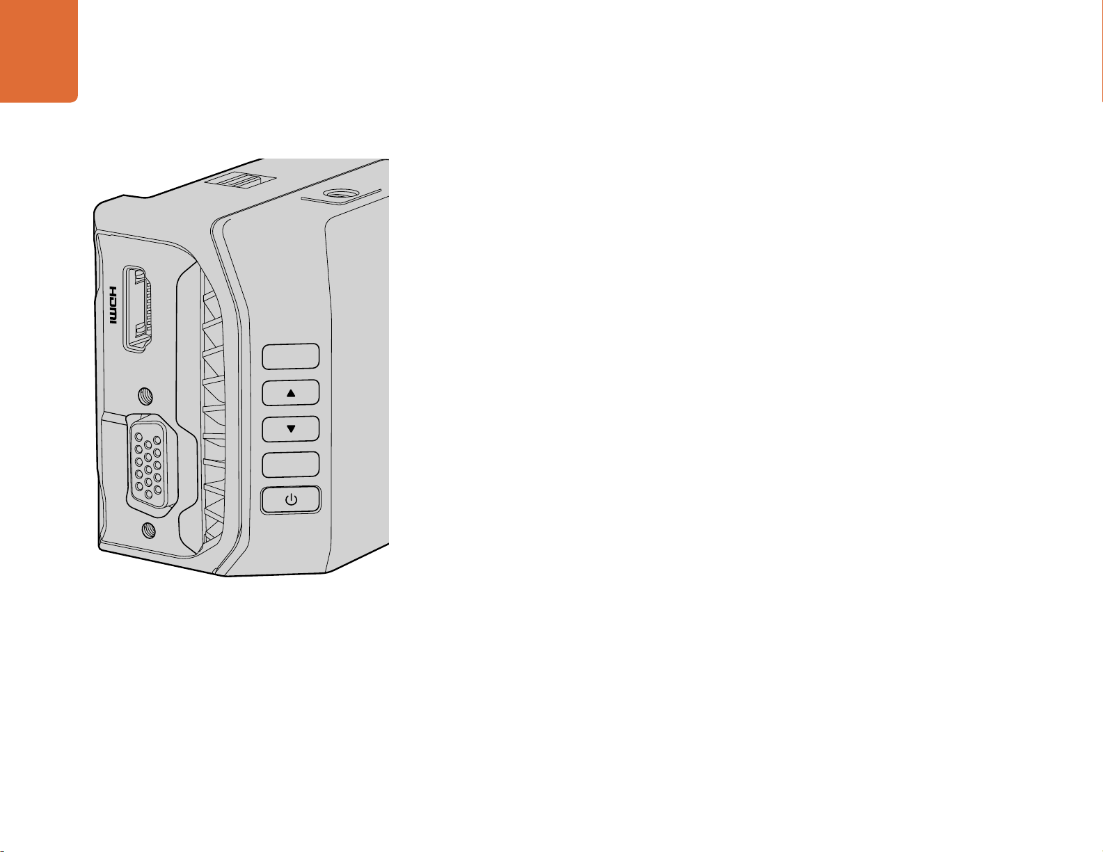
2. HDMI Out
The HDMI output lets you preview your video output and navigate the camera menus using external
monitors such as Blackmagic Video Assist. Output resolution is always 1080HD, regardless of the
recording resolution, and you can choose to display overlays such as frame guides, a histogram, and
audio levels. See the ‘monitoring settings’ section in this manual for more detail.
2
3
4
5
6
7
8
3. Expansion Port
DB-HD15 connector. Used for external power input and a range of remote control options as well as
reference input. See the section 'Blackmagic Micro Studio Camera 4K Expansion Cable' for details.
4. Menu Button
Use the menu buttons to access the camera's built in menu which can be displayed on an attached
HDMI display.
5. Up Button
Use the button to navigate menus.
6. Down Button
Use this button to navigate menus.
7. Set Button
Use this button to confirm your menu selections.
8. Power Button
Press the power button to turn on the Blackmagic Micro Studio Camera 4K. Press and hold the button
to turn the camera off.
Page 9
99 Camera Features
Right Panel
9. Analog Audio In
3.5mm stereo audio input, switchable between microphone and line-level input in menu.
9
10. SDI Out
10
SDI output for connecting to a switcher, external recorder or other device.
11
12
11. SDI In
SDI input allows camera control via ATEM switchers.
12. Headphone / Talkback
3.5mm jack for talkback with iPhone and Android style headsets. Double press the play/pause button
on your headset to toggle talkback on and press it once again to turn talkback off.
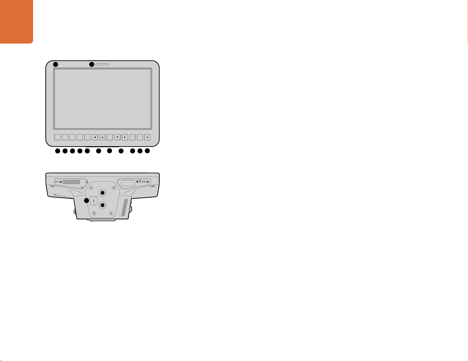
Rear Panel
13. Battery Slot
Blackmagic Micro Studio Camera 4K comes with one LP-E6 battery which fits into this slot. The battery
13
will be trickle charged while the camera is connected to power via its expansion port.
Top Panel
14. Battery Release
Slide forward to release the battery.
Bottom Panel
15. USB Connector
USB port for camera firmware updates. See the 'Blackmagic Camera Setup' section in this manual.
14
15
Page 10
Camera Connections
10
Camera Connections
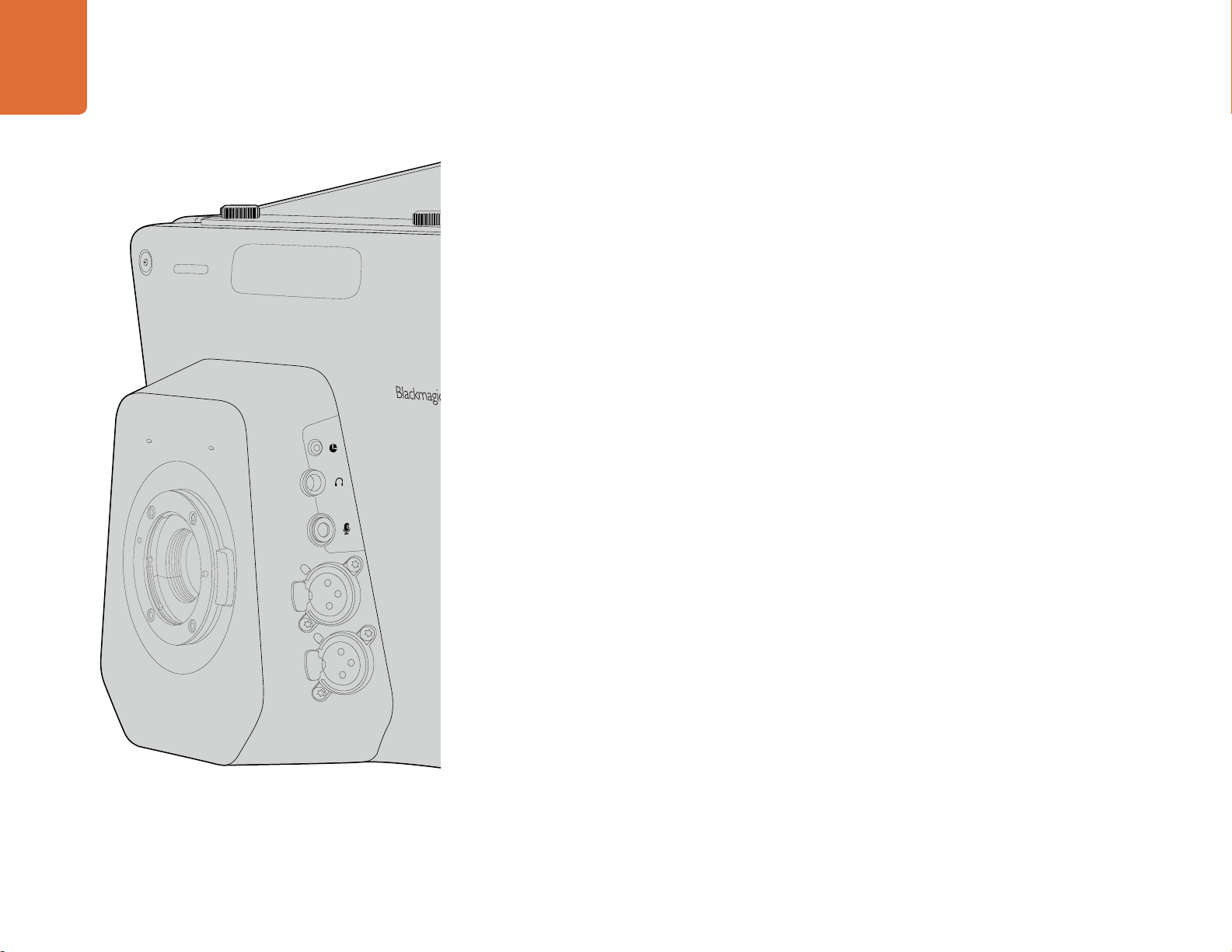
Blackmagic Studio Camera - Left Side
LANC Remote Control
The remote port on your camera is used to remotely control lens focus, iris and zoom adjustments
when using a compatible lens. The port takes a 2.5 mm stereo jack using the standard LANC protocol.
Active MFT lenses allow you to control the zoom servo with a LANC controller. The following lenses
are currently supported:
Panasonic Lumix G X Vario PZ 14-42mm f/3.5-5.6 Power O.I.S. Lens
Panasonic Lumix G X Vario PZ 45-175mm f/4.0-5.6 Zoom O.I.S. Lens
Olympus M.Zuiko Digital ED 12-50mm f/3.5-6.3 EZ Micro 4/3 Lens
Olympus M.Zuiko Digital ED 14-42mm f/3.5-5.6 EZ Micro 4/3 Lens
Headphones Output
For monitoring program and control room audio with aviation style headsets with "fixed wing"
connectors. Aviation headsets range from single ear models for use in studio environments to full
size noise cancelling models which are suitable for loud concerts or sporting events. Audio is taken
from channel 15 and 16 of the incoming SDI signal. Channels 15 and 16 are rarely if ever used during
production and so are very suitable to serve for the audio talkback.
1
PUSH
2
PUSH
1
3
2
1
3
2
For talking to the control room with aviation style headsets. Audio is embedded into channel 15 and
16 of the SDI signal output.
Audio Inputs
Two channels of professional balanced analog audio is supported via XLR connectors. Use the audio menu
to set the input levels for each channel. The inputs support both mic level inputs and line level inputs
and the input type is also selected from the audio menu. Audio is embedded into channel 1 and 2 of the
SDI stream.
Headphones Microphone Input
Page 11
11
Camera Connections
OPTICAL OUT
OPTICAL IN
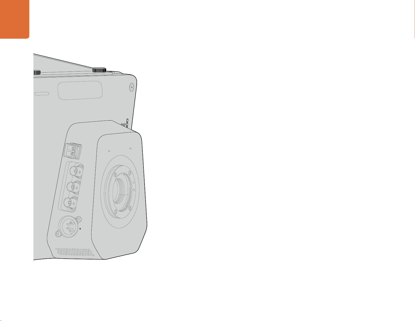
Blackmagic Studio Camera - Right Side
Optical Input/Output
For optical fiber input and output, you will need to install an optional optical fiber SFP module. This
lets you connect industry standard LC connectors, supporting 3G-SDI on Studio Camera HD, and
6G-SDI on Studio Camera 4K. Optical fiber cable is widely available because it's the same cable used
in computer networking. Optical fiber allows cable runs of up to 28 miles which is more than enough
for even the most demanding outside broadcast event. If both optical and SDI inputs are connected,
the output from the device which was connected first will be used. To purchase an optical fiber SFP
module for your Blackmagic Studio Camera, contact your nearest Blackmagic Design reseller. You
can find your nearest reseller on our website at www.blackmagicdesign.com/resellers.
SDI Out
Use the SDI Out connector to output 10-bit 4:2:2 video to professional SDI video equipment such
as routers, monitors, SDI capture devices and broadcast switchers. Blackmagic Studio Camera HD
supports 3G-SDI, and Studio Camera 4K supports 12G-SDI.
SDI OUT
SDI IN
REF
The SDI input allows the camera operator to view the Program (PGM) output. Simply press the PGM
button to toggle between live camera output and Program output from a switcher control room.
If both optical and SDI inputs are connected, the output from the device which was connected first will
be used. If you're using the Studio Camera to record to a device such as the Blackmagic Hyperdeck
Shuttle, the output from the Hyperdeck can be connected to the SDI input so you can playback what
you have just recorded.
Reference Input
SDI In
12V
This allows multiple cameras to be genlocked to a blackburst or tri-level reference signal. Genlocking
cameras to an external reference signal helps to prevent timing errors which may result in the picture
jumping when switching between different cameras.
Power
Use the 12 – 24V power input for connecting your power supply and to charge the internal battery.
When the battery is fully charged it will power the camera for up to 4 hours on Studio Camera HD,
and up to 3 hours on Studio Camera 4K .
Page 12
12
Camera Connections
MENU
Blackmagic Micro Studio Camera 4K - Left Side
HDMI Output
The HDMI port on your Blackmagic Micro Studio Camera 4K outputs 10-bit 4:2:2 1080p video with
2 channels of audio for monitoring purposes. You can connect any HD capable HDMI monitor, such
as Blackmagic Video Assist, to frame and focus shots as well as navigating the Micro Studio Camera
4K’s menus.
The frame rate of the HDMI output will match the format of the camera. For example, if the camera
is set to 2160p30, the HDMI output will be in 1080p30.
Expansion Port
Blackmagic Micro Studio Camera 4K’s small size makes it easy to capture unique shots from close to
the action or difficult to reach spots. While your Micro Studio Camera 4K can be easily tucked away out
of sight, the same can’t always be said of a camera operator. So being able to remotely control your
camera is important to making full use of its tiny size.
EXPANSION
SET
You can adjust some settings on Micro Studio Camera 4K via SDI input with an ATEM Switcher, as
detailed in the section 'Introducing Camera Control' in this manual. However, the majority of control
options are provided by the expansion port.
Blackmagic Micro Studio Camera 4K’s DB-HD15 connector provides a wide range of connections,
including power, LANC remote, pan, tilt, zoom and genlock via the expansion cable included.
We encourage you to use a wide range of easily available cables to access specific features, or to
solder your own custom connections and adapt the Micro Studio Camera 4K to your needs. See the
'Blackmagic Micro Studio Camera 4K Expansion Cable' section in this manual for more information.
Page 13
13
Camera Connections
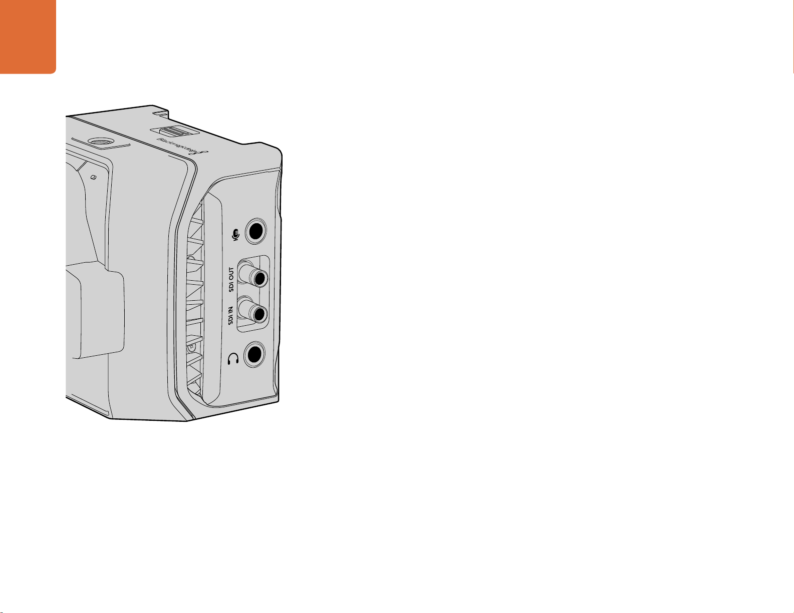
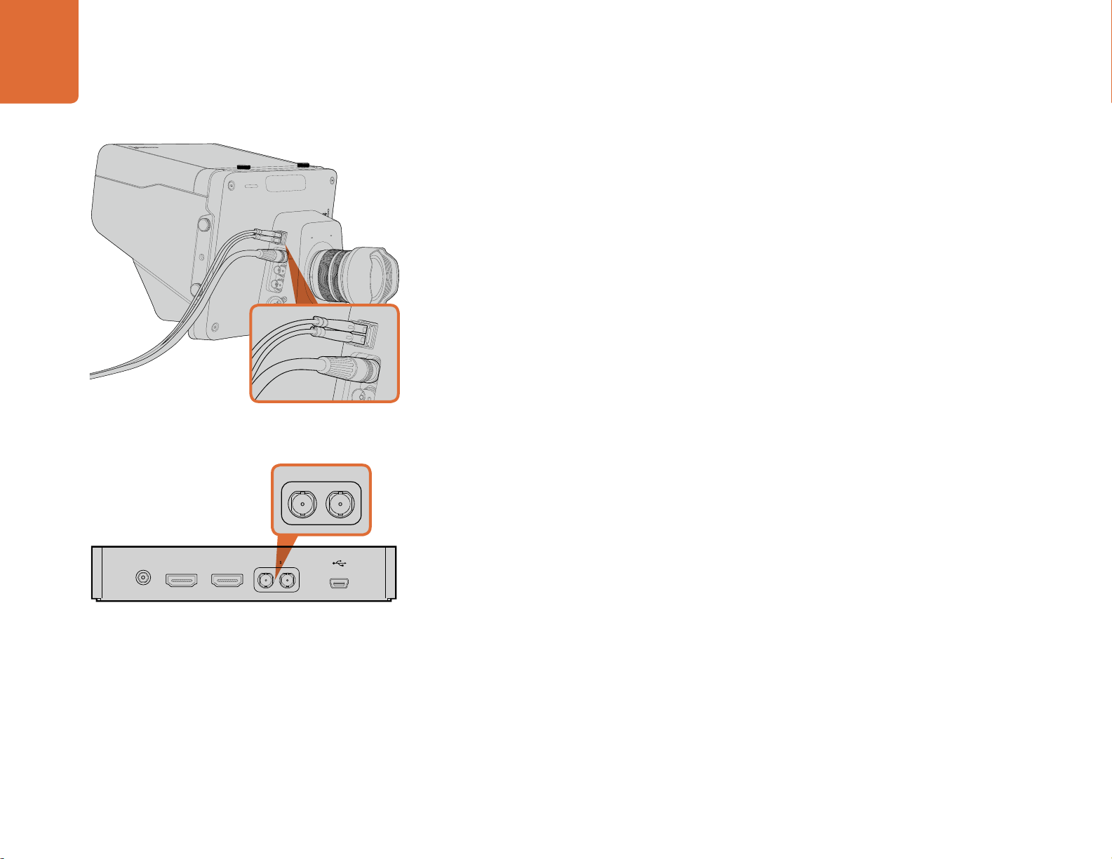
Blackmagic Micro Studio Camera 4K - Right Side
Analog Audio In
The 3.5mm stereo audio connector accepts microphone or line level audio. You can switch between
these options in the camera’s ‘audio settings’ menu. It’s important to select the appropriate setting
or your audio may sound too quiet or too loud.
SDI Out
Use the SDI out connector to output 10-bit 4:2:2 video to professional SDI video equipment such as
routers, monitors, SDI capture devices and broadcast switchers. Blackmagic Micro Studio Camera
4K supports 6G-SDI. You will need a DIN 1.0/2.3 to SDI adapter cable to connect to devices with full
size SDI connectors.
SDI In
Use the SDI in connector to control your Micro Studio Camera 4K via ATEM switchers. Refer to the
section ‘Introducing Camera Control’ for information about which controls are available.
Headphone / Talkback audio
The 3.5mm headphone / talkback input lets you talk to the control room with iPhone or Android style
headsets. Double press the play/pause button on your headset to enable talkback, and press once
to disable. Audio is embedded into channel 15 and 16 of the SDI signal output.
Page 14
Customization
Micro Studio Cam MSC Breakout Cable
14
Customization
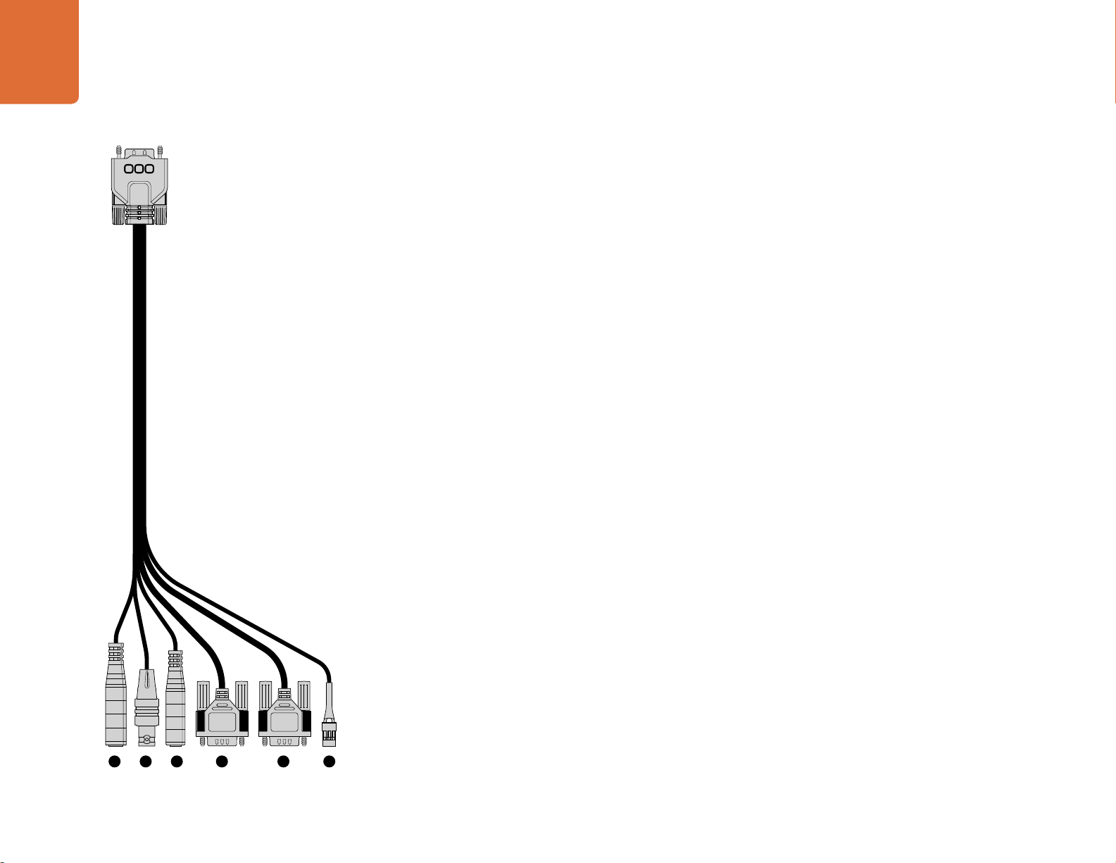
Blackmagic Micro Studio Camera 4K Expansion Cable
There are two ways to access the expansion port's functions. You can use the expansion cable that
comes with your Micro Studio Camera 4K, or solder your own custom connectors.
The expansion cable provides connectors for the following control options.
1. Power Input
The 12V power input connects via a DC jack and provides power to the Micro Studio Camera 4K,
as well as trickle charging any batteries attached. When mains power is supplied, the camera will
automatically turn on.
2. Reference Input
This allows multiple cameras to be genlocked to a blackburst or tri-level reference signal. Genlocking
cameras to an external reference signal helps to prevent timing errors which may result in the picture
jumping when switching between different cameras.
3. LANC
Connect wired LANC remote controllers to the 2.5mm jack for controlling functions like recording
start and stop, iris adjustment, and manual focus from a tripod arm when using compatible lenses.
4. Pan Tilt Zoom
The RS-422 connector is used to relay pan tilt zoom commands received by Micro Studio Camera 4K
from its SDI input to a motorized head.
1 2 3 4 5 6
Blackmagic Micro Studio Camera 4K expansion cable.
5. B4 Communication
The DB-9 connector allows you to power and control B4 broadcast lenses attached to the Micro
Studio Camera 4K via an MFT to B4 adapter. A B4 lens with digital serial communication can be
controlled, and power is supplied when the Micro Studio Camera 4K is connected to external power.
You can adjust settings such as iris, focus and zoom in the same way you would an active MFT lens either via an ATEM switcher using the ‘camera control’ menu, or via the other remote control
interfaces offered by the Micro Studio Camera 4K Expansion Cable.”
6. S.Bus Digital Servo
By connecting to a compatible S.Bus receiver using the Futaba J cable, you have 18 S.Bus remote
channels where features of the camera can be assigned to and remotely controlled. These features can
include focus, servo zoom, iris control and other such features. For more information about mapping
functions to S.Bus remote channels, see the ‘Remote Settings’ section of this manual.
Page 15
15
Customization
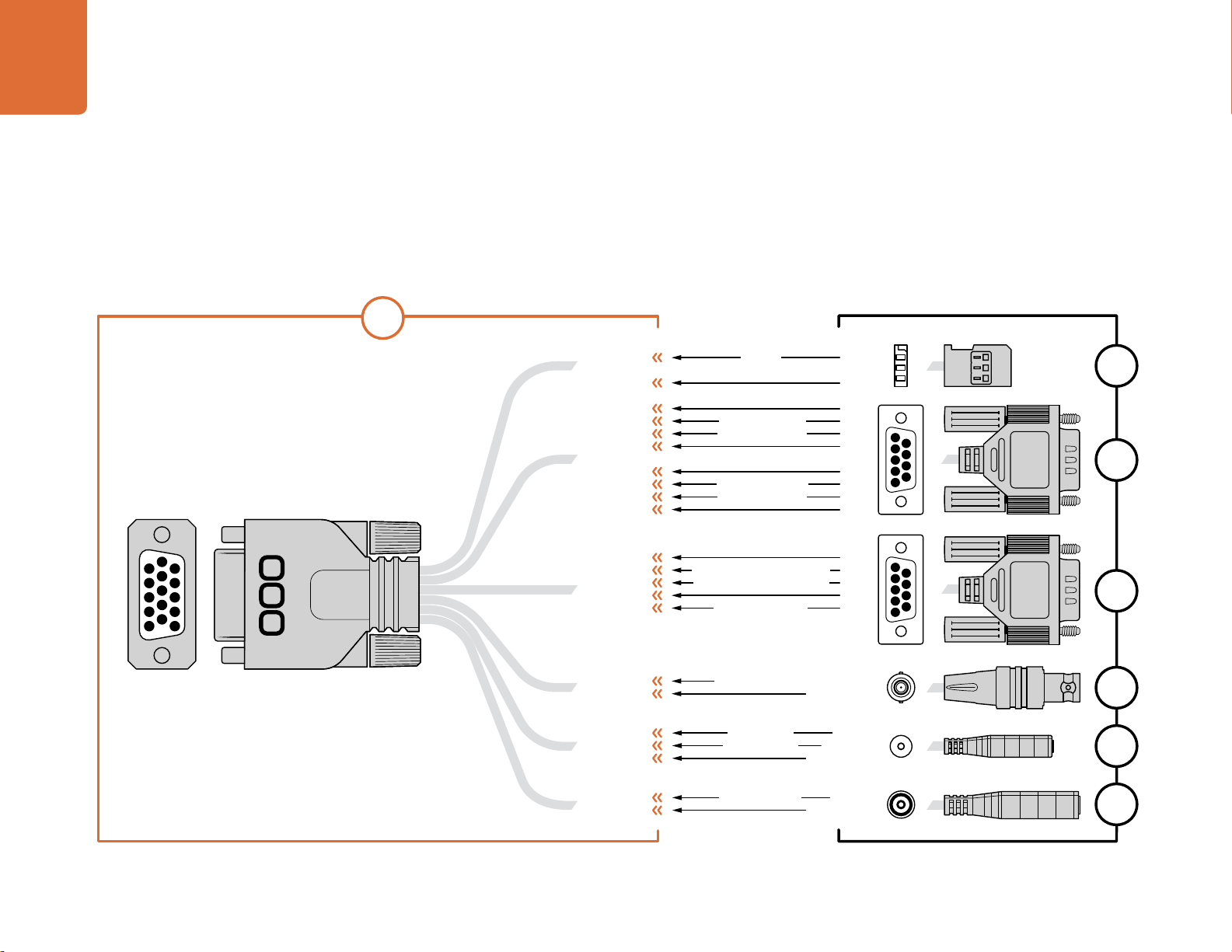
Wiring diagram for the Blackmagic Micro Studio Camera Expansion Cable
When using Blackmagic Micro Studio Camera 4K’s expansion port you may
only want to access one or two functions. For example, you may want to control
an attached B4 Broadcast Lens while simultaneously receiving 12V power and
a reference signal. It’s easy to make a connector that will give you just these
functions without the clutter of additional, unused connectors.
Use the following diagram when wiring the expansion cable included or use it
as an example for how you can wire up the connections on your own custom
cable correctly. The full range of available pins are listed under group P1,
while the subsets used for particular functions, as well as their layout within
the appropriate connectors, are shown in groups P2 through P7.
10
5
15
9
4
14
8
3
13
7
2
12
6
11
1
1 Ground
2 S. Bus
3 PTZ RS422 Tx-
4 Ground
5 Reference Input
6 Power +12V in
7 Ground
8 PTZ RS422 Tx+
9 LANC Data
10 LANC Power
P1
11 Ground
12 PTZ RS422 Rx-
13 PTZ RS422 Rx+
14 B4 Lens Control Transmit
15 B4 Lens Control Receive
GROUND
GROUND
GROUND
GROUND
GROUND
GROUND
GROUND
GROUND
GROUND
GROUND
PIN ASSIGNMENT
2
12
8
13
3
14
15
6
5
9
10
6
PTZ RS422 RxPTZ RS422 Tx+
PTZ RS422 Rx+
PTZ RS422 Tx-
B4 Lens Control Transmit
B4 Lens Control Receive
Power +12V in*
Reference Input
LANC Data
LANC Power
Power +12V in
S. Bus
OTHER
CENTER
SLEEVE
TIP
RING
SLEEVE
PIN
SLEEVE
1
2
P2
3
1
2
3
5
4
5
6
7
9
4
8
3
7
2
6
1
P3
8
9
1
5
2
3
4
5
9
4
8
3
7
2
6
1
P4
P5
P6
P7
Page 16
Camera Settings
16
Camera Settings
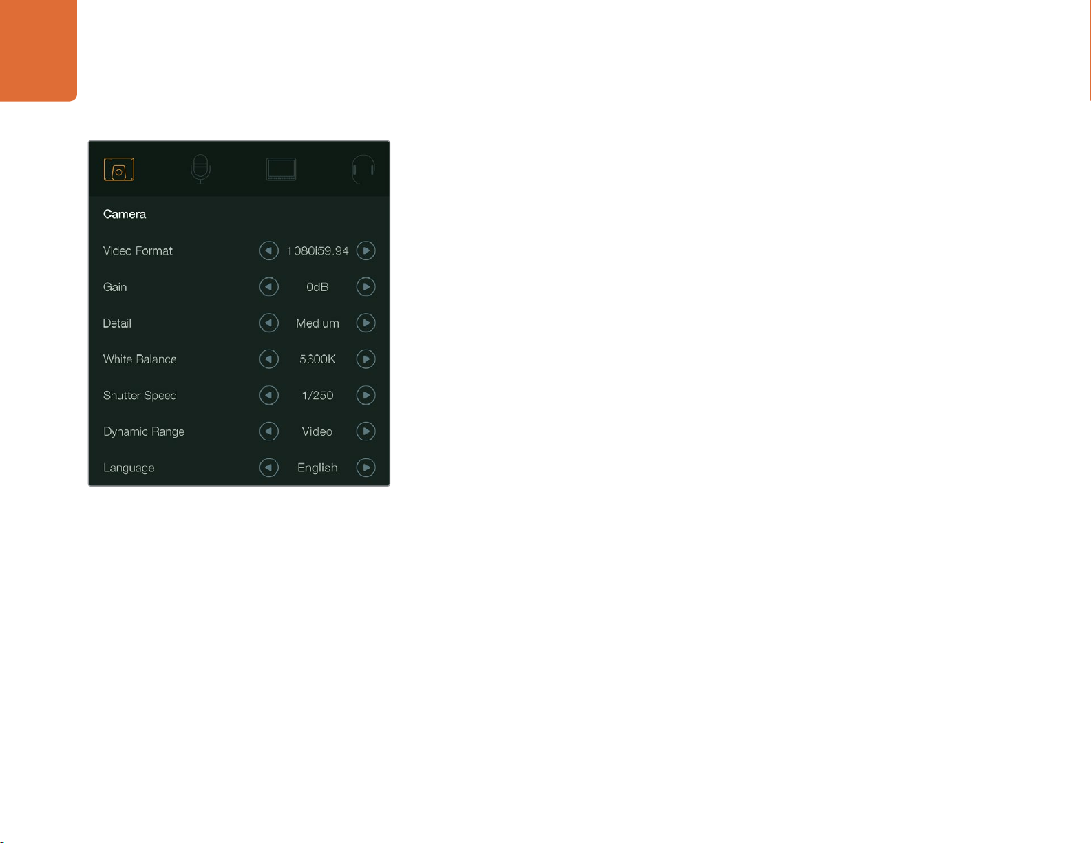
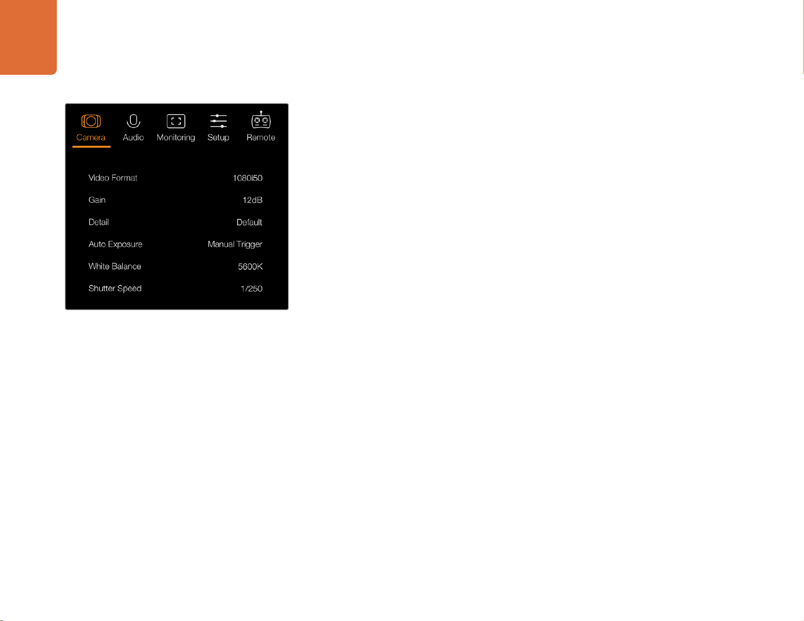
Camera settings - Blackmagic Studio Camera.
Camera Settings
To configure settings on your Blackmagic Studio Camera or Blackmagic Micro Studio Camera 4K,
press the 'menu' button. Use the menu navigation buttons to highlight menus and press the 'set'
button to confirm your selection.
If you are using the Micro Studio Camera 4K, you will need to connect an external monitor via the
camera's HDMI port to view menu settings.
Video Format
Select your desired video format using the navigation buttons. For example, to select between
1080p and 1080i formats, press the left or right arrow buttons to progress through the format options.
Press the 'set' button to confirm the format you want.
Turn the page to see a list of supported video formats.
Gain
Gain settings are helpful when you are shooting in low light conditions. The default setting is 0dB
and gain can be increased in 6dB increments up to 18dB.
Detail
Use this setting to sharpen your image live from your Studio Camera. Decrease or increase the level
of sharpening by selecting 'off' or 'default' for low sharpening, 'medium' and 'high'.
Auto Exposure
Blackmagic Micro Studio Camera 4K gives you several auto exposure options.
Iris
Maintains a constant shutter speed while changing the aperture to achieve a constant exposure.
Shutter
Maintains a constant aperture while changing the shutter speed to achieve a constant exposure.
Iris + Shutter
Mantains the correct exposure levels by adjusting the aperture. If the maximum or minimum available
aperture is reached and exposure still cannot be maintained, Micro Studio Camera 4K will begin
adjusting the shutter speed to keep exposure constant.
Page 17
17
Camera Settings
Camera settings - Blackmagic Micro Studio Camera 4K.
Shutter + Iris
Maintains the correct exposure levels by adjusting the shutter speed. If the maximum or minimum
available shutter speed is reached and exposure still cannot be maintained, Micro Studio Camera
4K will begin adjusting the aperture to keep exposure constant.
Manual Trigger
Iris aperture and shutter speed are set manually and exposure may vary with changing light
conditions.
White Balance
Eighteen white balance presets are selectable for a variety of color temperature conditions.
2500, 2800, 3000, 3200, 3400, 3600, 4000, 4500 and 4800K for various conditions under
tungsten, incandescent or fluorescent light, or under dull natural light including candle light,
sunrise/sunset, morning, and after noon light.
5000, 5200, 5400 and 5600K for outdoors on a clear, sunny day.
6000, 6500, 7000, 7500 and 8000K for a variety of daylight conditions.
Shutter Speed
Shutter speed complements the gain setting by regulating the amount of light on the sensor. There
are 15 different shutter speeds available ranging from 1/50 sec to 1/2000 sec.
Page 18
18
Camera Settings
Blackmagic Studio Cameras Supported Video Formats
All Studio Cameras Micro Studio Camera 4K
Additional Formats
720p50 2160p23.98 2160p23.98
720p59.94 2160p24 2160p24
720p60 2160p25 2160p25
1080i50 2160 p29.97 2160 p29.97
1080i59.94 2160p30 2160p30
1080i60 2160p50
1080p23.98 2160 p59.94
1080p24 2160p60
1080p25
1080p29.97
1080p30
1080p50
1080p59.94
1080p60
Studio Camera 4K
Additional Formats
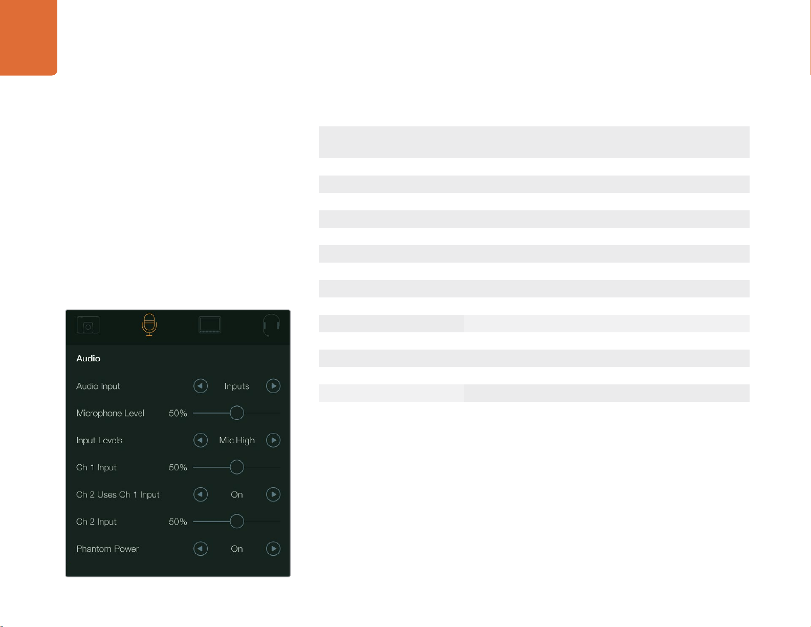
Audio Settings
Audio settings - Blackmagic Studio Camera.
To adjust audio input and audio monitoring settings on your Blackmagic Studio Camera, press the
'menu' button and select the microphone icon to the left of the display. Use the menu navigation
buttons to highlight menus and use the 'set' button to confirm your selection.
Automatic Gain Control
Blackmagic Micro Studio Camera 4K features an automatic audio gain control setting that lets camera
adjust the audio recording levels. It automatically reduces the audio gain levels if the input level gets
too loud and subtly raises it if it is too low.
Audio Input
Switches audio between using the camera's internal microphone and the XLR audio connectors.
Page 19

19
Camera Settings
Microphone Level
Microphone input adjusts the recording levels of the built in microphone. Move the audio slider left
or right to increase or decrease levels. Studio Camera has a built in stereo microphone. The built in
microphone records to audio channels 1 and 2 when no external audio source is connected.
Input Level
External audio connectors support audio at microphone level or line level. Select Line when connecting
external audio equipment such as an audio mixer or amplifier. Select the mic low or mic high setting
depending on the signal strength of your microphone. It's important to select the appropriate level
to avoid your external audio sounding almost inaudible or too hot and distorted. Set the external
audio input levels by using the left and right arrows.
Ch 1 Input
Move the audio slider icon left or right to increase or decrease levels for channel 1. The external audio
input overrides the built in microphone and is output to audio channel 1.
Ch 2 Uses Ch 1 Input
Select 'on' if you want to embed channel 1 external audio into channels 1 and 2 of the SDI or the
optional optical fiber output. This is the same as connecting input 1 to both audio channels in the
camera and is useful when using microphones with a single mini audio output and you need to connect
both stereo audio channels to it. Select this setting to off if you want channel 1 audio to remain on
one channel only and channel 2 will take audio from the channel 2 audio input, which is preferred
when using stereo audio sources.
Ch 2 Input
Move the audio slider icon left or right to increase or decrease levels for channel 2. The external
audio input overrides the built in microphone and is output to audio channel 2.
Phantom Power
Phantom power supplies power through microphone cables and is a convenient power source for
condenser microphones. Enable or disable phantom power for studio cameras with XLR inputs by
navigating to the 'audio' menu and selecting on or off using the arrow buttons. Phantom power is
automatically disabled when the 'line input level' setting is selected. Be sure to wait at least 10 seconds
for phantom power to discharge after disconnecting before plugging in a self powered microphone.
Older ribbon type microphones are not suitable for phantom power usage.
Page 20
20
Camera Settings
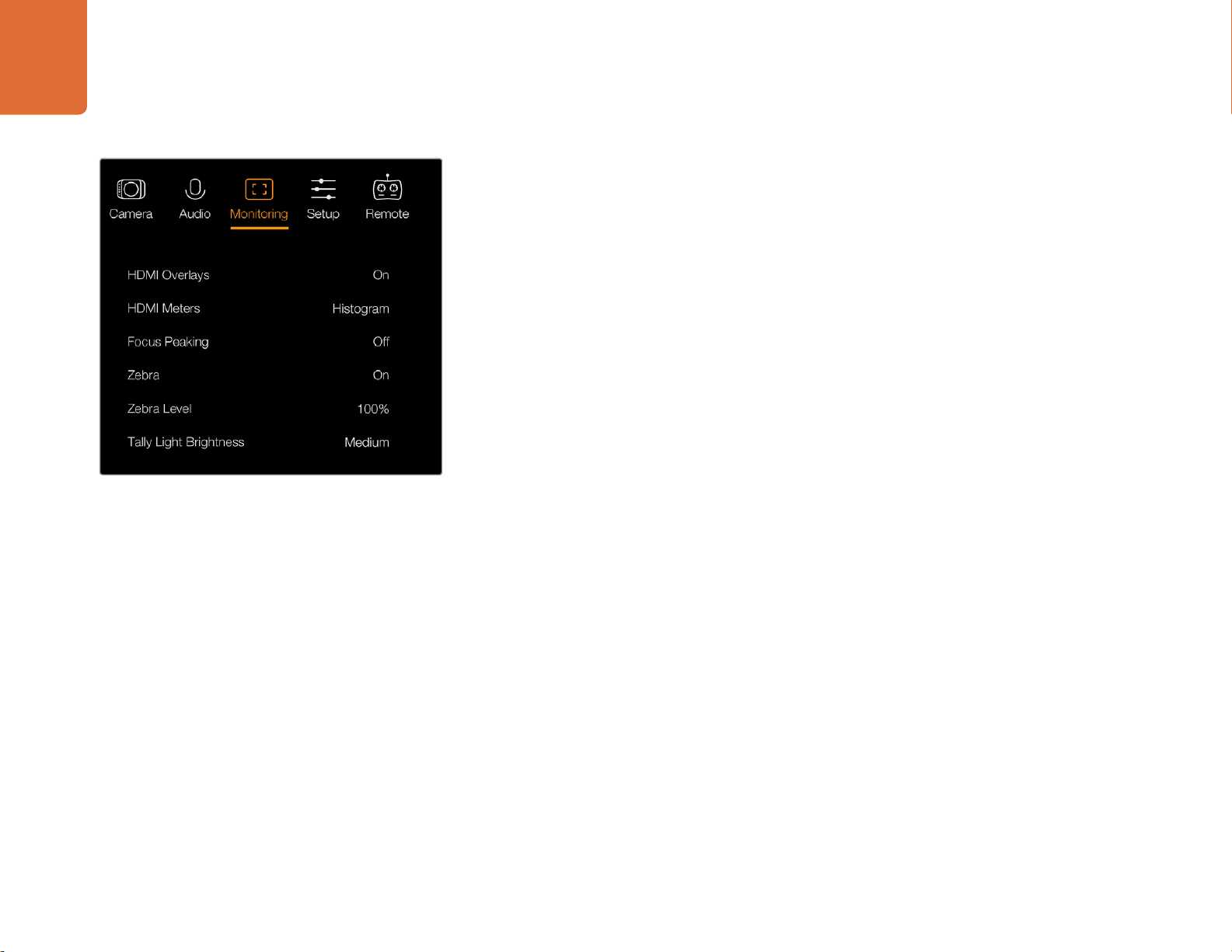
Monitoring Settings
To adjust the display settings for the LCD, press the 'menu' button and select the monitor icon. Use
the menu navigation buttons to highlight menus and use the 'set' button to confirm your selection.
HDMI Meters
Blackmagic Micro Studio Camera 4K gives you the option to select which meters you want to display
on the HDMI output.
Histogram
The histogram shows the contrast between whites and blacks along a horizontal scale. The left edge
of the histogram displays shadows, or blacks, and the far right displays highlights, or whites. When
you close or open the lens aperture, you'll notice the information in the histogram moves to the left
or right accordingly.
This setting toggles the histogram on and off. When on, this will appear in the bottom right corner
of an attached monitor when 'HDMI overlays' are set to on.
Monitoring settings - Blackmagic Micro Studio Camera 4K.
Audio
The audio meter represents the current volume of left and right audio channels in two horizontal
bars. Left is on top, right is on the bottom. If your audio levels rise too high, your audio peaks can be
clipped and you will hear distortion in your audio. To avoid this, adjust the audio gain on your camera
until your audio levels stay within safe levels.
This setting toggles the audio meter on and off. When on, this will appear in the bottom left corner
of an attached monitor when 'HDMI overlay' are set to on.
HDMI Overlays
This setting is only available on Micro Studio Camera 4K. When set to 'on,' HDMI video output
will include frame guides and information about the camera settings and identity, as well
as any meters enabled via the 'HDMI meters' setting.
Brightness
Move the slider icon left or right to adjust brightness settings for the LCD. The default setting is 60%.
Zebra
Blackmagic Cameras have a zebra feature which gives an indication of exposure levels. Diagonal lines
will appear across any part of the video that exceeds the zebra exposure level.
Turn zebra on and select the desired zebra warning level by using the left and right arrows. The
default setting is medium.
Page 21
21
Camera Settings
Focus Peaking
Allows you to change the level of focus peaking. The settings include: off, low, medium and high.
Adjust this setting when you are using a very sharp lens and the peaking covers the entire image.
The default setting is medium.
Front Tally Brightness
Changes the brightness of the front tally light. Settings include: off, low, medium and high. The
default setting is medium.
Rear Tally Brightness
Changes the brightness of the rear tally light. Settings include: low, medium and high. The default
setting is medium.
Tally Light Brightness
Changes the brightness of the tally light on Micro Studio Camera 4K. The default setting is medium.
Display Battery Percentage
Some LP-E6 batteries can tell the camera their charge levels directly via digital serial communication.
If this option is enabled, you can display the battery levels for Micro Studio Camera 4K using a
percentage value instead of graphical bars. However, if you find the percentage display inaccurate, you
can switch back to using graphical bars which measures of the state of charge directly off the battery.
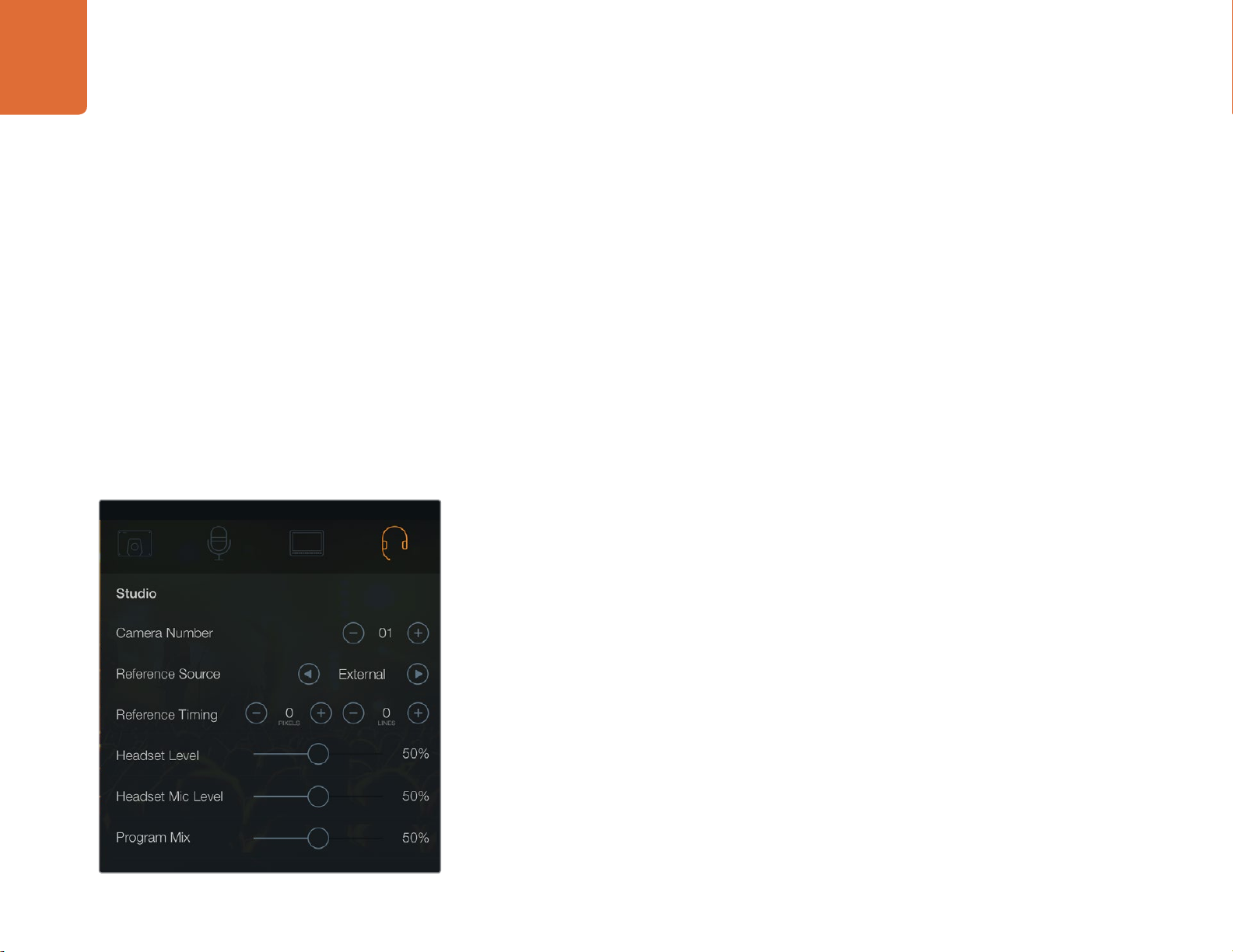
Studio settings - Blackmagic Studio Camera.
Studio Settings
To adjust the display settings for the LCD, press the 'menu' button and select the headphones icon.
Use the menu navigation buttons to highlight menus and use the 'set' button to confirm your selection.
Camera Number
If you want your Studio Camera to receive tally signals from an ATEM switcher, you'll need to set
the camera number on your camera. This ensures the switcher sends the tally signal to the correct
camera. The camera number can be set to a value of 1-99. Default setting is 1.
Reference Source
Used to select the genlock source. The Studio Camera can lock to program SDI input or external
genlock source. If using an external genlock source, be aware that changing that source will most
likely cause a glitch as the camera locks to the new source.
Reference Timing
Allows you to manually adjust the reference timing on a line or pixel basis.
Page 22
22
FOCUS
IRIS PTT PGM LUT SET DISPLAY MENU
Camera Settings
Remote settings - Blackmagic Micro Studio Camera 4K.
Headset Level
Move the volume slider left or right to increase or decrease audio monitoring levels. The default
setting is 50%.
Headset Mic Level
Move the volume slider left or right to increase or decrease audio microphone input levels. The
default setting is 50%.
Program Mix
Changes the balance of camera sound to talkback sound. The headphones will output audio following
what is displayed on the LCD. For instance, if you are in camera view, camera audio is heard. And if
you are in program view, program audio is heard. The default setting is 0%.
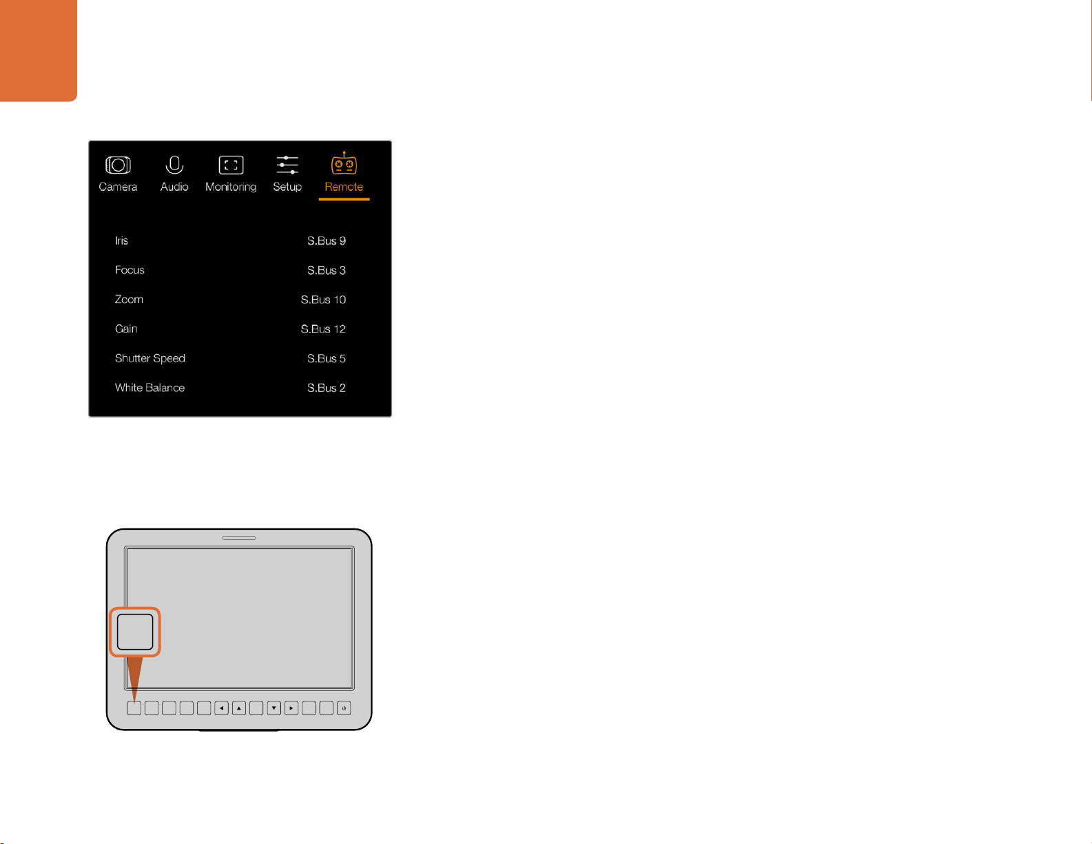
Remote Settings
Blackmagic Micro Studio Camera 4K features an additional menu for setting remote functions. If you
are using S.Bus to control your camera, you can use this menu to assign functions such, iris, shutter
speed and so on to individual S.Bus channels. Simply select the function you wish to control and
assign an available channel using the ‘up,’ ‘down’ and ‘set’ buttons.
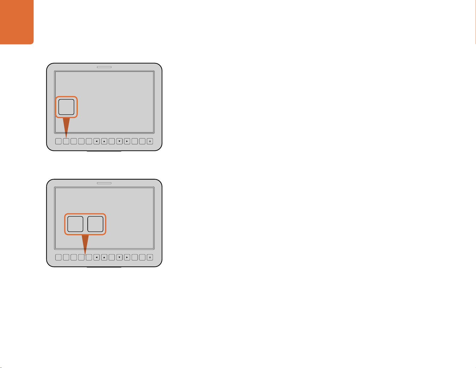
Button Settings
Adjusting Lens Settings
Blackmagic Studio Camera supports electronic lens control, which allows you to adjust lens settings
such as aperture and auto focus. The focus peaking feature creates a green edge around the sharpest
parts of the image so you can easily confirm your focus. Focus peaking is only visible on the LCD and
does not affect the SDI output.
Focus Button
When using the Studio Camera with an auto focus lens, press the focus button for focus peaking
or auto focus. Press the focus button once to auto focus. A quick double press of the focus button
activates focus peaking.
FOCUS
IRIS PTT PGM LUT SET DISPLAY MENU
Press the focus button once to auto focus. A quick double
press of the focus button activates focus peaking.
When using a manual lens, press the focus button once for focus peaking.
Iris Button
When using video dynamic range settings, a single press of the iris button will set an average exposure
based on the highlights and shadows in your shot. When using film dynamic range settings, pressing
the iris button sets your exposure to accommodate the brightest highlight in your shot. To set your
aperture manually on your Studio camera, press the up and down menu navigation buttons.
Page 23
23
IRIS PTT PGM LUT SET DISPLAY MENU
Camera Settings
FOCUS
IRIS PTT PGM LUT SET DISPLAY MENU
Additional Settings
Push to Talk (PTT) Button
When doing live production it's vital that camera operators can talk to the director and others within
the control room. Simply press and hold the button to begin talking. Press twice in quick succession
for hands free communication. Press again to revert to the default behavior.
Program (PGM) Button
It's sometimes important for camera operators to see the program output, rather than just the view
from their own camera. Press the button to toggle between live camera output and the program
output from a switcher control room. You can use either the SDI input, or user upgradable optical
fiber input to connect your external video source.
Press the iris button for auto exposure or use the up and down
navigation controls for manual exposure.
FOCUS
IRIS PTT PGM LUT SET DISPLAY MENU
The Studio Camera features settings like PTT and PGM which
are essential for live production.
Look Up Table (LUT) Button
Currently not implemented.
Left, Up, Down, Right Buttons
Use these buttons to navigate the menus.
Set Button
Use this button to confirm your menu selections.
Display Button
Press this button to display useful information on your Studio Camera's 10" monitor, including:
Frame guides with camera and lens settings such as camera number, video format and frame
rate, shutter speed, white balance, battery life, gain setting and f-stop number.
Press the Disp button again to turn overlays off and monitor the image only. Overlays are visible on
the 10" monitor. The SDI output is always clean.
Menu Button
Press this button to bring up the menu and then use the arrow buttons to navigate.
Power Button
Press the power button to turn on the Blackmagic Studio Camera. Press and hold the button to turn
the camera.
Page 24
OPTICAL OUT
OPTICAL IN
SDI OUT
Camera Video Output
24
Camera Video Output
OPTICAL OUT
OPTICAL IN
SDI OUT
SDI IN
REF
12V
Connect your Studio Camera to a switcher via SDI, or via
optical fiber with user upgradable SFP module installed.
Connecting to Video Switchers
Blackmagic Studio Cameras output 10-bit 4:2:2 video so you can connect to broadcast switchers
and other SDI video equipment. With the user upgradable SFP module installed you can connect via
optical fiber, which means ATEM Camera Converters are not required at the camera end.
If you're using a Blackmagic Studio Camera HD or Studio Camera 4K, you can easily view the Program
(PGM) output from the switcher by connecting it to your Studio Camera's SDI input, or to the
optical fiber input when the user upgradable SFP module is installed.
Blackmagic Studio Camera also features a reference input which allows multiple cameras to be
genlocked to a blackburst or tri-level reference signal. Genlocking cameras, VTRs and other devices
to an external reference signal helps to eliminate timing errors which may result in the picture jumping
when switching between different sources.
Connecting to Recorders
If you simply wish to record your Studio Camera's output, you can connect the SDI output to the
SDI input of an SSD recorder such as the Blackmagic HyperDeck Shuttle. The SDI output from the
HyperDeck can then be connected to the Studio Camera's SDI input, so you can view your recordings
on the camera's LCD.
+12V POWER HDMI IN HDMI OUT SDI IN SDI OUT
Connect the camera's SDI output to the HyperDeck's SDI
input and connect the HyperDeck's SDI output to the
camera's SDI input to view your recordings.
Page 25
25
1
PUSH
2
PUSH
SDI OUT
OPTICAL OUT
OPTICAL IN
SDI IN
REF
12V
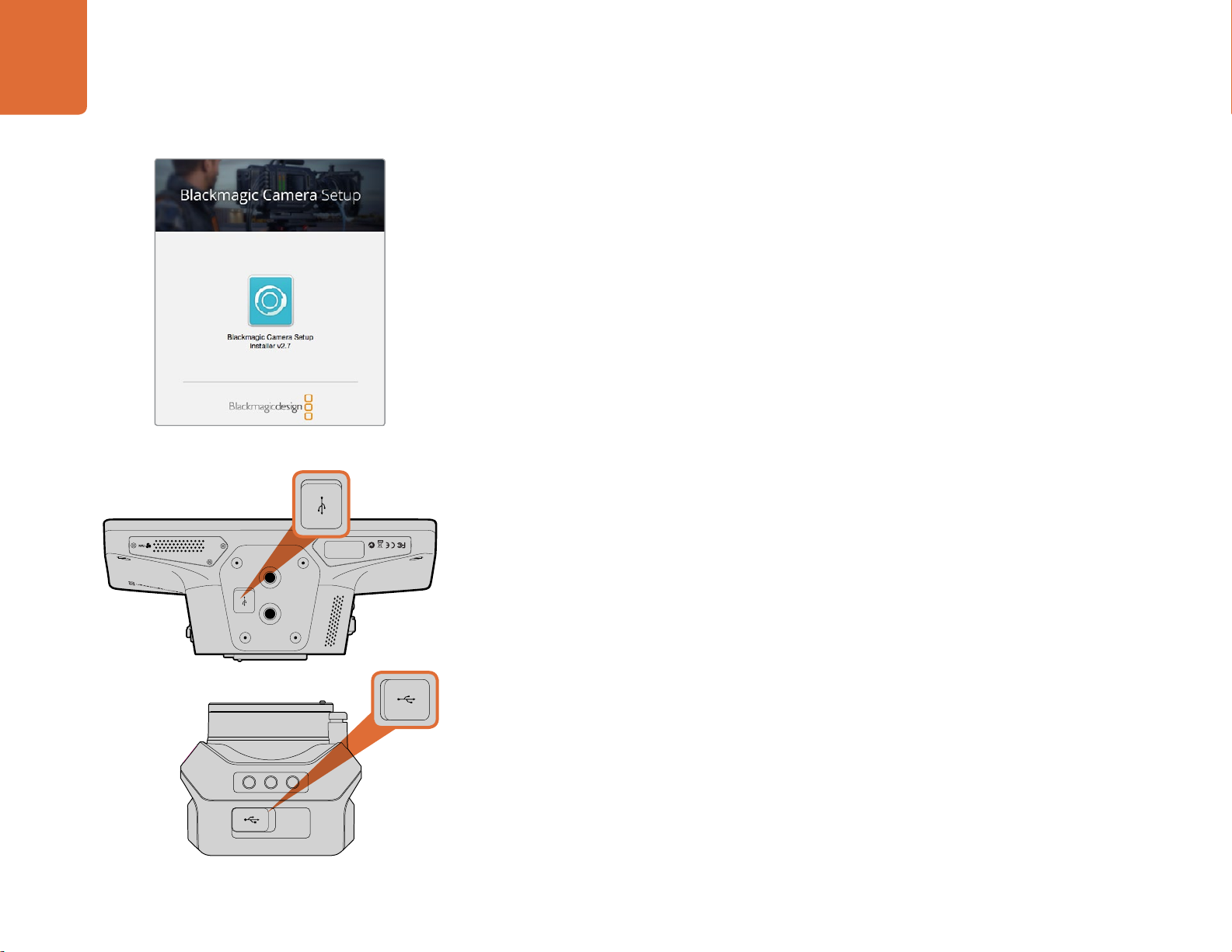
Blackmagic Camera Setup
Blackmagic Camera Setup software.
How to Update Your Camera Software on Mac OS X
After downloading the ‘Blackmagic Camera Setup’ software, unzip the downloaded file and double
click on the .dmg disk image file. Launch the 'Blackmagic Camera Setup' installer and follow the
onscreen instructions.
How to Update Your Camera Software on Windows
After downloading the ‘Blackmagic Camera Setup’ software and unzipping the downloaded file,
you should see a ‘Blackmagic Camera Setup’ installer window. Double click on the installer icon and
follow the onscreen prompts to complete the installation.
After the installation is complete, click on the Windows 'start' menu, and go to 'all programs'. Click on
the Blackmagic Design folder to open the Blackmagic Camera setup software and instruction manuals.
How to Update your Camera's Internal Software
After installing the latest Blackmagic Camera setup software on your computer, connect a USB cable
between the computer and your camera. The Mini-B USB 2.0 port is located on the underside of
the camera.
Launch 'Blackmagic Camera Setup' and follow the onscreen prompts to update the camera software.
The Mini-B USB 2.0 ports are located on the underside
of the cameras.
Page 26
Attaching Accessories
26
Attaching Accessories
Sun Shade
The Studio Cameras include a foldable sun shade to shade the LCD in bright conditions and ensure
optimum viewing is possible at all times.
Step 1. Locate the 6 thumbscrews that are included with your Studio Camera.
Step 2. Align the holes in the sun shade with the camera's mounting points and screw in
2 thumbscrews to the top and each side of the camera to firmly secure the sun shade.
Other Accessories
For studio use, you might want to mount the camera on a pedestal and add rails for large broadcast
lenses and teleprompters. For outside broadcast use, your may want to attach microphones, external
batteries, or LANC remote controllers. The camera includes two 3/8” mounting points on the bottom,
and ten 1/4” mounting points on the sides and the top. This means you have the flexibility to customize
your rig for any size production.
Page 27
PUSH PUSH
SDI INPUTS REF IN AUX 1-3 PREVIEW PROGRAM OUTPUTS MULTI-VIEW ANALOG AUDIO IN
STEREO IN
REMOTE
ANALOG AUDIO OUT
CH 1
All SDI and HDMI video connections are
SD, HD and Ultra HD switchable unless indicated
CH 2CH 1 CH 2
IN
1
IN2IN
1
IN
3
IN
4
IN
5
IN
6
IN
7
IN
8
IN
9
IN
10
2
1 321
HD HD HD
PUSH PUSH
STEREO IN
REMOTE
ANALOG AUDIO OUT
CH 1
All SDI and HDMI video connections are
SD, HD and Ultra HD switchable unless indicated
CH 2CH 1 CH 2
21HD HD HD
4321
OPTICAL OUT/IN
SDI OUT
L R
OPTICAL OUT/IN
SDI OUT
L R
ANALOG AUDIO OUT OPTICAL OUT/IN
SDI OUT
L R
ANALOG AUDIO OUT OPTICAL OUT/IN
SDI OUT
L
OUT
R
ANALOG AUDIO OUTANALOG AUDIO OUT
IN
PGM SDI
OUT
IN
MIC
OUT
IN
H/PHONE
AES/EBU TALKBACK LOOPS
OUT
IN
PGM SDI
OUT
IN
MIC
OUT
IN
H/PHONE
AES/EBU TALKBACK LOOPS
Using ATEM Software Control
27
Using ATEM Software Control
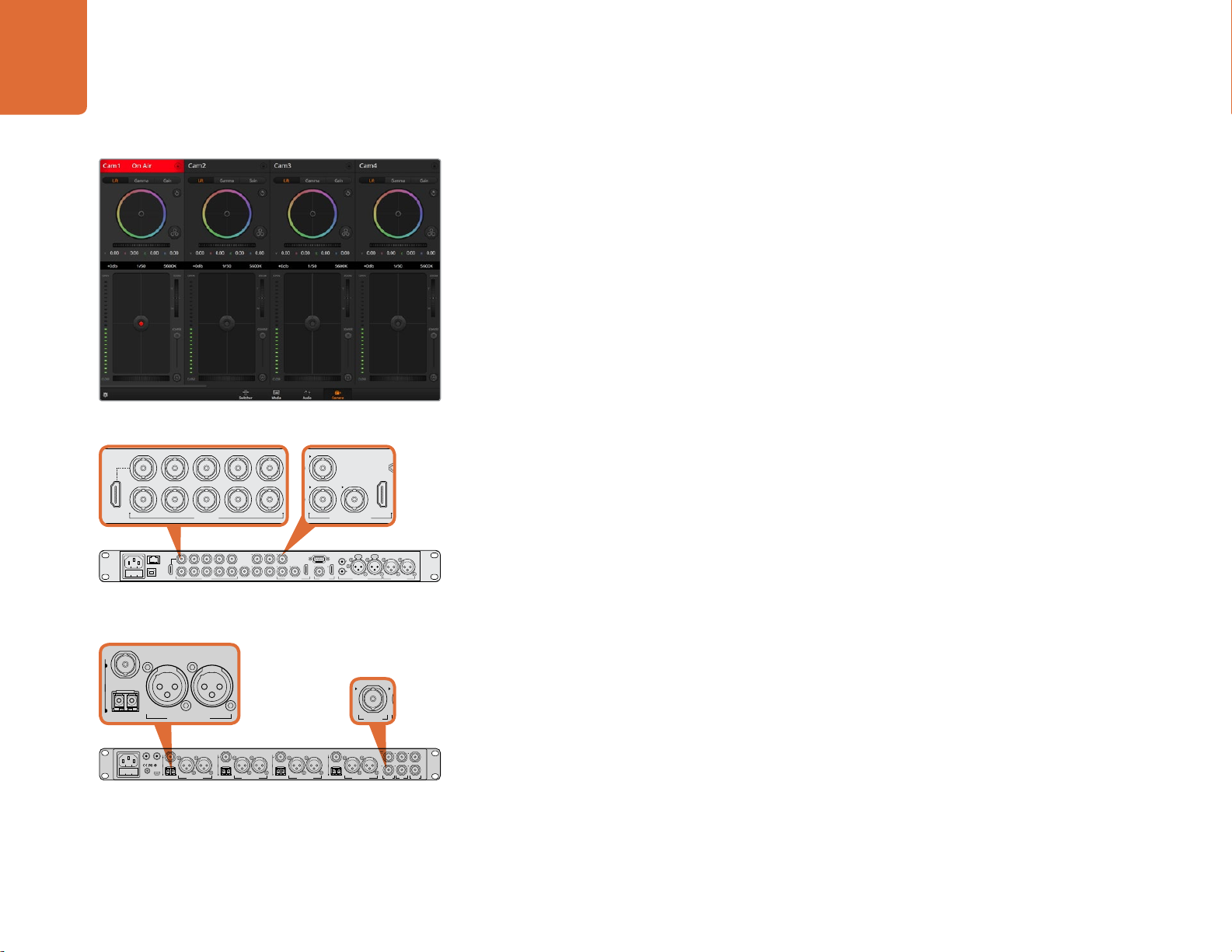
Introducing Camera Control
Your Blackmagic Studio Camera can be controlled from an ATEM switcher using the Camera Control feature
in ATEM Software Control. Clicking on the Camera button opens the camera control feature. Settings such
as iris, gain, focus and zoom control are easily adjusted using compatible lenses, plus you can color balance
cameras and create unique looks using the DaVinci Resolve primary color corrector.
The ATEM switcher control works by broadcasting camera control packets via all the non down conver ted SDI outputs
of an ATEM switcher. So this means you can connect an SDI output of an ATEM switcher to your camera's video input,
your camera will detect the control packets in the SDI link and allow you to control features in the camera itself. You
can control your camera via both regular SDI, or via user upgradable
Connecting via SDI
ATEM Camera Control.
CONTROL
USB 2.0 HDMI IN
IN
5
3
1
IN
IN
IN2IN
6
4
1
SDI INPUTS REF IN AUX 1-3 PREVIEW PROGRAM OUTPUTS MULTI-VIEW ANALOG AUDIO IN
7
IN
8
9
IN102
1 321
IN
IN
IN
IN
HD HD HD
REMOTE
STEREO IN
PUSH PUSH
All SDI and HDMI video connections are
SD, HD and Ultra HD switchable unless indicated
CH 1
ANALOG AUDIO OUT
CH 2CH 1 CH 2
Connect your Blackmagic Studio Camera to any of the ATEM
switcher's SDI inputs.
Step 1. Connect your Blackmagic Studio Camera's SDI Out to any SDI In on the ATEM switcher.
Step 2. Connect any one of the ATEM switcher's SDI outputs, except down converted or multi view
Step 3. On your Blackmagic Studio Camera, press Menu. Navigate to Studio Settings>Camera
Connecting via Optical Fiber
Step 1. With the user upgradable optical fiber SFP module installed in your Studio Camera, connect
optical
fiber when the SFP module is installed.
outputs, to your Studio Camera's SDI In. Camera control signals are not sent via the multi view
and down converted SDI outputs.
Number and set it to match the switcher input. For example, if studio camera 1 is connected to
Cam 1 on the ATEM switcher, the camera number must also be set to 1. This ensures tally is
sent to the correct camera.
the Optical Out/In to the Optical Out/In on an ATEM Studio Converter.
Connect multiple Blackmagic Studio Cameras via optical fiber
using an ATEM Studio Converter.
Step 2. Connect a suitable SDI out from ATEM Studio Converter to any SDI In on the ATEM switcher.
Step 3. Connect any one of the ATEM switcher's SDI outputs, except down converted or multi view
outputs to ATEM Studio Converter's SDI In. Camera control signals are not sent via the multi
view and down converted SDI outputs.
AES/EBU TALKBACK LOOPS
OUT
OUT
OUT
IN
IN
IN
R
PGM SDI
MIC
H/PHONE
Step 4. On your Blackmagic Studio Camera, press Menu. Navigate to Studio Settings>Camera Number
and set it to match the switcher input. For example, if studio camera 1 is connected to Cam 1
RL
SDI OUT
+12V BACKUP
POWER
USB 2.0
OPTICAL OUT/IN
L R
SDI OUT
OPTICAL OUT/IN
L R
ANALOG AUDIO OUT OPTICAL OUT/IN
SDI OUT
L R
ANALOG AUDIO OUT OPTICAL OUT/IN
4321
SDI OUT
L
ANALOG AUDIO OUTANALOG AUDIO OUT
on the ATEM switcher, your camera number must also be set to 1. This ensures tally is sent to
the correct camera.
Open ATEM Software Control Preferences and set the switcher's button mapping to make sure you are
switching the right camera with correct tally. Now you have a video connection from the switcher to your
Blackmagic Studio Camera, you can also get the advantage of live tally indicators on your camera, as well
as being able to view the program feed of the switcher by pressing your camera’s PGM button.
Page 28
28
Using ATEM Software Control
Using Camera Control
Launch ATEM Software Control and click on the Camera button located at the bottom of the software
window. You’ll see a row of labeled camera controllers containing tools to adjust and refine each camera’s
image. The controllers are easy to use. Simply click the buttons using your mouse, or click and drag to adjust.
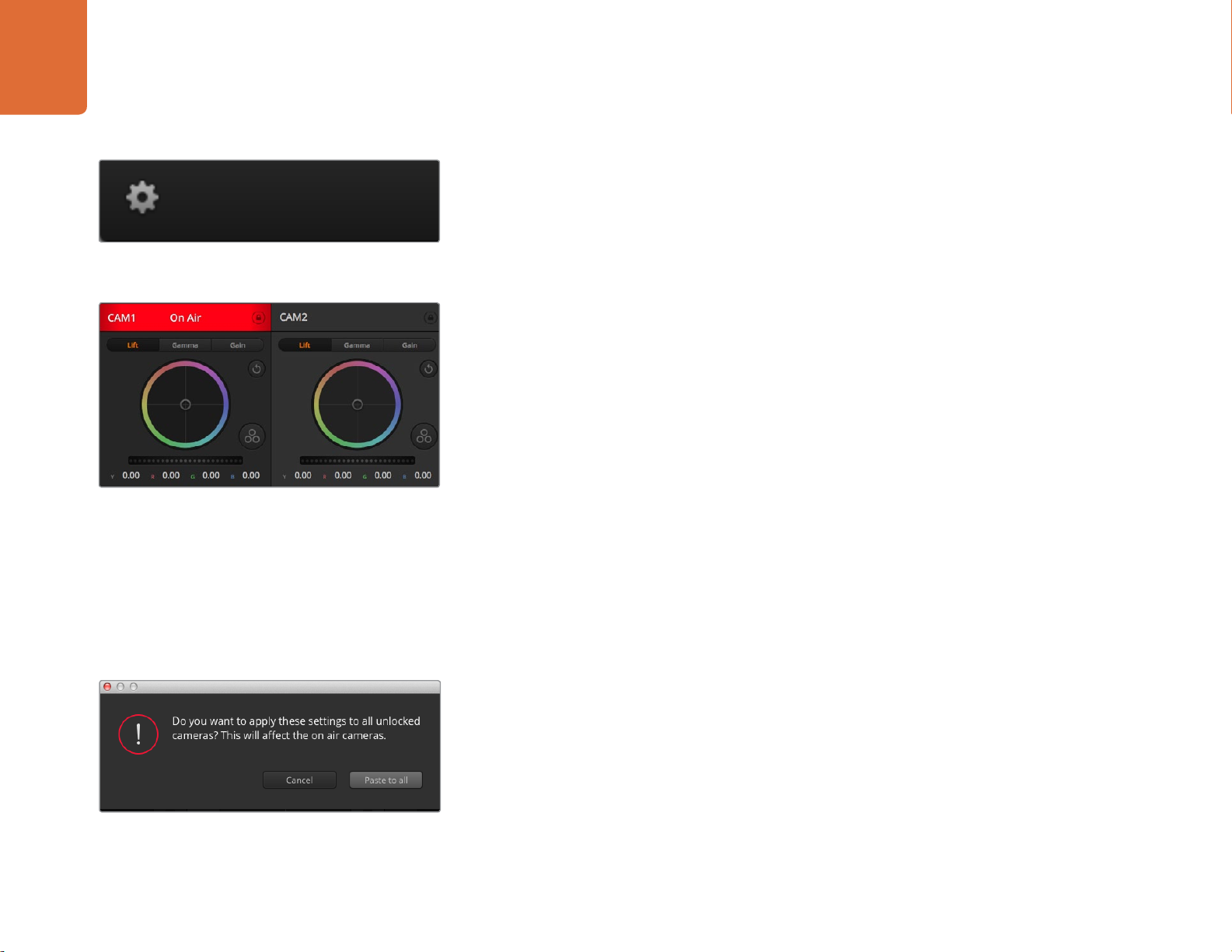
Click on the settings icon to select the Aux output for
camera control.
Each camera controller displays the channel status so you
know which camera is on air. Use the color wheels to adjust
each YRGB channel's lift, gamma and gain settings.
Camera Control Selection
The button row at the top of the camera control page lets you select the camera number you would
like to control. If you have more cameras that fit onto the window size, or you are running the color
corrector window, then you can use these buttons to select between which camera you would like
to control. If you are using an Aux output for monitoring your camera control, pushing these buttons
to change the camera to control will also send that camera's video output to the Aux output setup
in the switcher preferences.
Channel Status
The channel status at the top of each camera controller displays the camera label, On Air indicator
and lock button. Press the lock button to lock all the controls for a specific camera. When on air, the
channel status illuminates red and displays the On Air alert.
Color Wheel
The color wheel is a powerful feature of the DaVinci Resolve color corrector and used to make color
adjustments to each YRGB channel’s lift, gamma and gain settings. You can select which setting to
adjust by clicking on the three selection buttons above the color wheel.
When applying Paste to all, a warning message will appear
asking you to confirm your action. This is so you don’t
accidentally paste new settings to any unlocked cameras
that are currently on air.
Master Wheel
Use the master wheel below the color wheel to make contrast adjustments to all YRGB channels at
once, or luminance only for each lift, gamma or gain setting.
Reset Buttons
The reset button near the top right of each camera controller lets you easily choose color correction
settings to reset, copy or paste. Each color wheel also has its own reset button. Press to restore a setting
to its default state, or copy/paste a setting. Locked controllers are not affected by the Paste feature.
The master reset button on the top right corner of the color corrector panel lets you reset lift, gamma
and gain color wheels plus Contrast, Hue, Saturation and Lum Mix settings. You can paste color
correction settings to camera controllers individually, or all cameras at once for a unified look. Iris,
focus, coarse and pedestal settings are not affected by the Paste feature. When applying Paste to
all, a warning message will appear asking you to confirm your action. This is so you don’t accidentally
paste new settings to any unlocked cameras that are currently on air.
Page 29
29
Using ATEM Software Control
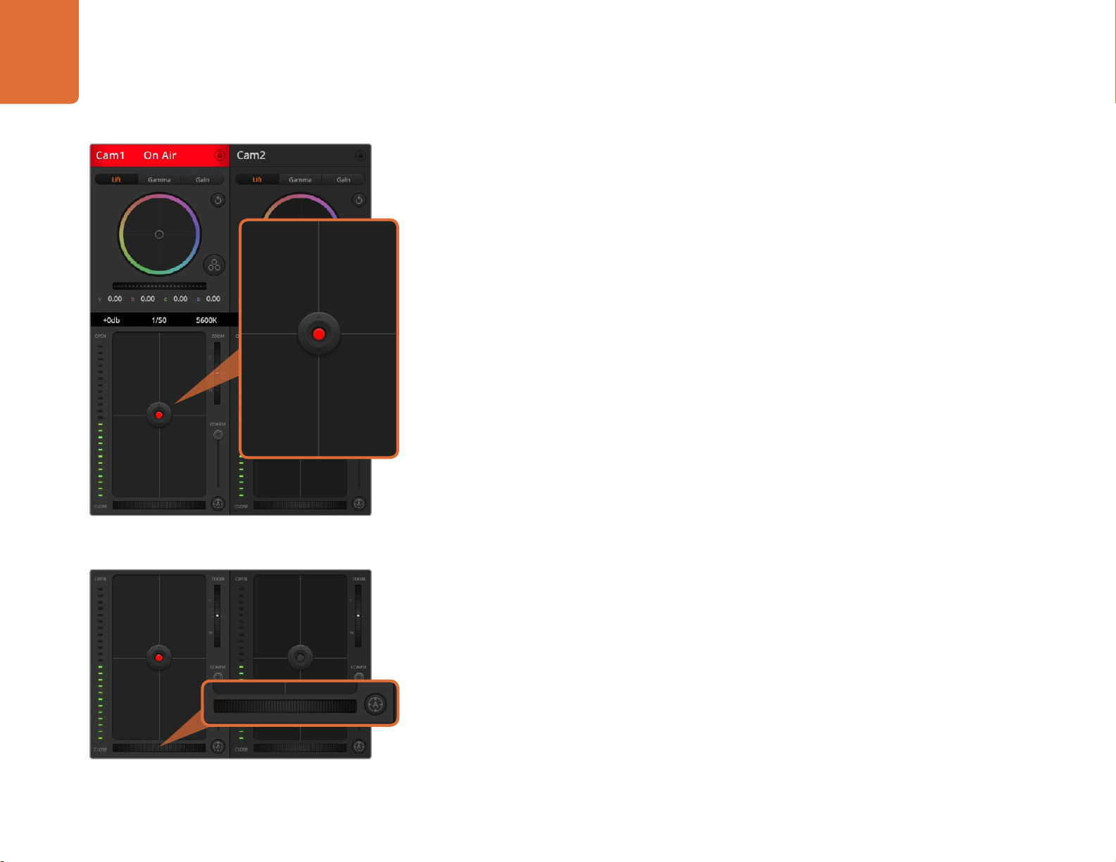
Iris/Pedestal Control
The iris/pedestal control is located within the cross hairs of each camera controller. The control
illuminates red when its camera is on air.
To open or close the iris, drag the control up or down. Holding the shift key allows only iris adjustments.
To darken or lift the pedestal, drag the control left or right. Holding the command key on a Mac, or
the Control key on Windows, allows only pedestal adjustments.
Zoom Control
When using compatible lenses with an electronic zoom feature, you can zoom your lens in and out
using the zoom control. The controller works just like the zoom rocker on a lens, with telephoto on
one end, and wide angle on the other. Click on the zoom control, located above the coarse slider,
and drag up to zoom in, or drag down to zoom out.
If your lens does not have active lens control or your camera does not support zoom control via the
SDI camera control protocol then these settings will have no affect. If you are using Blackmagic Studio
Camera or Blackmagic Studio Camera 4K, please make sure you have updated your camera software
to v1.9.11 or later to ensure your camera has support for controlling MFT lenses with active zoom.
Coarse Setting
The coarse setting is located to the left of the iris/pedestal control and is used to limit the iris range.
The iris/pedestal control illuminates red when its
respective camera is on air.
This feature helps you prevent over exposed images from going to air.
To set your coarse threshold, completely open the iris using the iris control, then drag the coarse
setting up or down to set optimum exposure. Now when you adjust the iris, the coarse threshold will
prevent it from going above optimum exposure.
Click on the auto focus button or drag the manual focus
adjustment left or right to focus a compatible lens.
Iris Indicator
The iris indicator is located to the right of the iris/pedestal control and displays a visual reference
so you can easily see how open or closed the lens aperture is. The iris indicator is affected by the
coarse setting.
Auto Focus Button
The auto focus button is located at the bottom left corner of each camera controller. Press to
automatically set the focus when you have an active lens that supports electronic focus adjustments. It's
important to know that while most lenses support electronic focus, some lenses can be set to manual
or auto focus modes, and so you need to ensure your lens is set to auto focus mode. Sometimes this
is set by sliding the focus ring on the lens forward or backward.
Page 30
30
Using ATEM Software Control
Manual Focus Adjustment
When you want to adjust the focus on your camera manually, you can use the focus adjustment
located at the bottom of each camera controller. Drag the wheel control left or right to manually
adjust focus while viewing the video feed from the camera to ensure your image is nice and sharp.
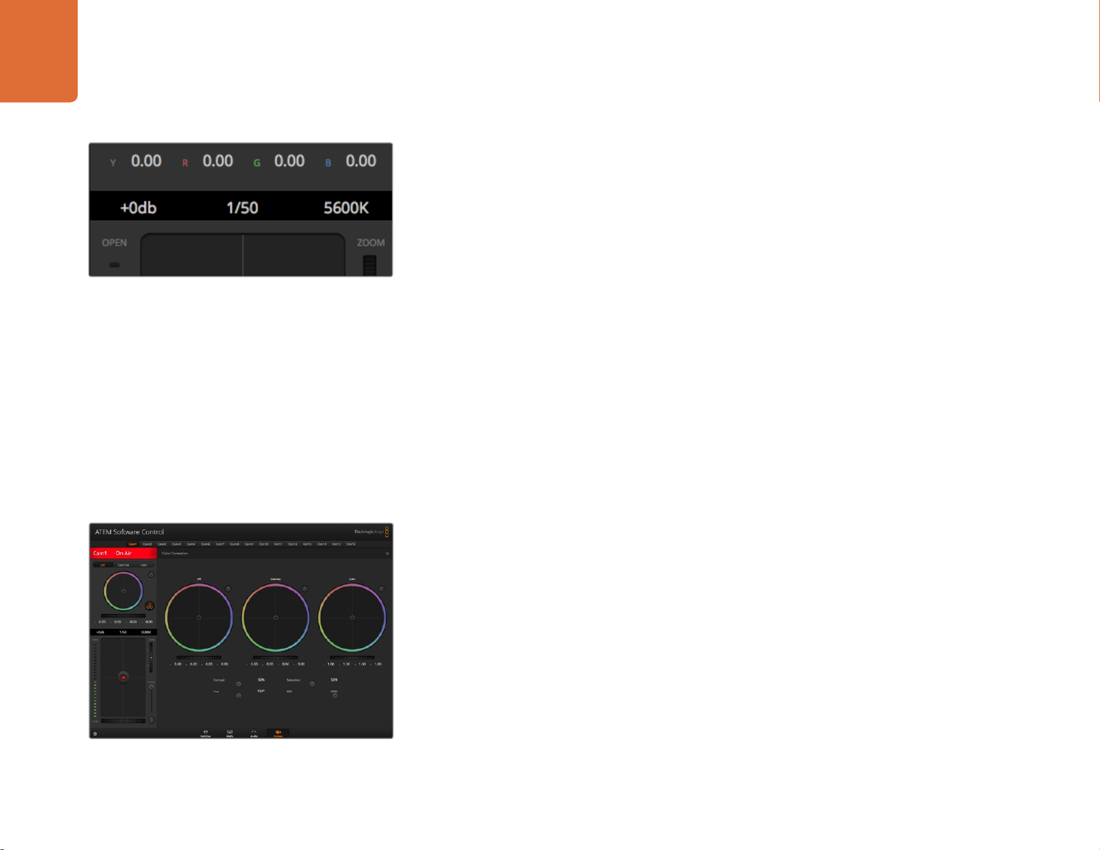
Camera Gain
The camera gain setting allows you to turn on additional gain in your camera. This is important when
you are operating in low light conditions and need extra gain in the front end of your camera to avoid
Hovering your mouse pointer over the gain, shutter speed
and white balance indicators reveal arrows you can click on
to adjust their respective settings.
your images being under exposed. You can decrease or increase gain by clicking on the left or right
arrows on the dB gain setting.
You can turn on some gain when you need it, such as outdoor shoots when the light fades at sunset and you
need to increase your image brightness. It's worth noting that adding gain will increase noise in your images.
Shutter Speed Control
The shutter speed control is located in the section between the color wheel and the iris/pedestal
control. Decrease or increase the shutter speed by hovering your mouse pointer over the shutter
speed indicator and then clicking on the left or right arrows.
If you see flicker in lights you can decrease your shutter speed to eliminate it. Decreasing shutter
speed is a good way to brighten your images without using camera gain because you are increasing
the exposure time of the image sensor. Increasing shutter speed will reduce motion blur so can be
used when you want action shots to be sharp and clean with minimal motion blur.
Click on the DaVinci Resolve primary color corrector button
to expand the color correction window and adjust settings.
White Balance
The white balance setting next to the shutter speed control can be adjusted by clicking on the left
or right arrows on each side of the color temperature indicator. Different light sources emit warm or
cool colors, so you can compensate by adjusting the white balance. This ensures the whites in your
image stay white.
DaVinci Resolve Primary Color Corrector
If you have a color correction background, then you can change the camera control from a switcher
style CCU interface to a user interface that's more like a primary color corrector on a post production
color grading system.
Your Blackmagic Studio Camera features a DaVinci Resolve primary color corrector built in. If you have
used DaVinci Resolve, then creatively, grading in your Blackmagic Studio Camera will be identical so
you can use your color grading experience for live production.
Page 31

31
Using ATEM Software Control
The color corrector panel can be expanded out of any camera controller and provides expanded
color correction control with extra settings and a full primary color corrector interface.
You have color wheels and settings such as saturation available and you can see shadows, mid tones
and highlight settings all at the same time. Simply switch between cameras using the camera selection
controls at the top of the window as you need.
Color Wheels
The Lift/Gamma/Gain controls allow tonally specific yet overlapping regions of adjustment.
In photographic terms lift, gamma and gain corresponds to shadows, mid tones and highlights.
Lift, gamma and gain color wheels in the color
corrector panel.
Use the color wheels in the following ways to make fine or aggressive adjustments:
Click and drag anywhere within the color ring: Note that you don’t need to drag the
color balance indicator itself. As the color balance indicator moves, the RGB parameters
underneath change to reflect the adjustments being made to each channel.
Shift-Click and drag within the color ring: Jumps the color balance indicator to the
absolute position of the pointer, letting you make faster and more extreme adjustments.
Double-click within the color ring: Resets the color adjustment without resetting the master
wheel adjustment for that control.
Click the reset control at the upper-right of a color ring: Resets both the color balance
control and its corresponding master wheel.
Adjust the master wheels by dragging the wheel control left
or right.
Drag the sliders left or right to adjust Contrast, Saturation,
Hue and Lum Mix settings.
Master Wheels
Use the master wheels below the color wheels to adjust each YRGB channels’ lift, gamma and
gain controls.
To make adjustments using the master wheel:
Drag the master wheel left or right: Dragging to the left darkens the selected parameter
of the image, dragging to the right lightens that parameter. As you make an adjustment, the
YRGB parameters underneath change to reflect the adjustment you’re making. To make a
Y-only adjustment, hold down the ALT or Command key and drag left or right. Because the
color corrector uses YRGB processing, you can get quite creative and create unique affects
by adjusting the Y channel only. Y channel adjustments work best when the Lum Mix setting
is set to the right side to use YRGB processing vs the left side to use regular RGB processing.
Normally, most DaVinci Resolve colorists use the YRGB color corrector as you get a lot more
control of color balance without affecting overall gain, so you spend less time getting the
look you want.
Page 32

32
Using ATEM Software Control
Contrast Setting
The Contrast setting gives you control over the distance between the darkest and lightest values of
an image. The effect is similar to making opposing adjustments using the lift and gain master wheels.
The default setting is 50%.
Contrast, Saturation, Hue and Lum Mix settings.
Saturation Setting
The Saturation setting increases or decreases the amount of color in the image. The default
setting is 50%.
Hue Setting
The Hue setting rotates all hues of the image around the full perimeter of the color wheel. The default
setting of 180 degrees shows the original distribution of hues. Raising or lowering this value rotates
all hues forward or backward along the hue distribution as seen on a color wheel.
Lum Mix Setting
The color corrector built into your Blackmagic Studio Camera is based on the DaVinci Resolve primary
color corrector. DaVinci has been building color correctors since the early 1980’s and most Hollywood
films are color graded on DaVinci Resolve than any other method.
This means the color corrector built into your Blackmagic Studio Camera has some unique and
creatively powerful features. The YRGB processing is one of those features.
When color grading, you can choose to use RGB processing, or YRGB processing. High end colorists
use YRGB processing because you have more precise control over color and you can independently
adjust the channels with better separation and more creative options.
When the Lum Mix control is set to the right side, you have the 100% output of the YRGB color
corrector. When you have the Lum Mix control set to the left side, you get 100% output of the RGB
corrector. You can set the Lum Mix to any position between the left and right to get a blend of output
from both the RGB and YRGB correctors.
Which is the correct setting to use? That's up to you, as color correction is a pure creative process
and there is no right and wrong, and the best setting is what you like the most and what you think
looks good!
Synchronizing Settings
When connected, camera control signals are sent from the ATEM switcher to your Blackmagic Studio
Camera. If a setting is accidentally adjusted from your Studio Camera, camera control will automatically
reset that setting to maintain synchronization.
Page 33

Developer Information
33
Developer Information
Blackmagic Video Device Embedded Control Protocol
Version 1.0
If you are a software developer you can use the Video Device Embedded Control Protocol to construct
devices that integrate with our products. Here at Blackmagic Design, our approach is to open up our
protocols and we eagerly look forward to seeing what you come up with!
Overview
This document describes an extensible protocol for sending a uni-directional stream of small control
messages embedded in the non-active picture region of a digital video stream.
The video stream containing the protocol stream may be broadcast to a number of devices. Device
addressing is used to allow the sender to specify which device each message is directed to.
Assumptions
Alignment and padding constraints are explicitly described in the protocol document. Bit fields are
packed from LSB first. Message groups, individual messages and command headers are defined as,
and can be assumed to be, 32 bit aligned.
Blanking Encoding
A message group is encoded into a SMPTE 291M packet with DID/SDID x51/x53 in the active region
of VANC line 16.
Message Grouping
Up to 32 messages may be concatenated and transmitted in one blanking packet up to a maximum
of 255 bytes payload. Under most circumstances, this should allow all messages to be sent with a
maximum of one frame latency.
If the transmitting device queues more bytes of message packets than can be sent in a single frame,
it should use heuristics to determine which packets to prioritise and send immediately. Lower priority
messages can be delayed to later frames, or dropped entirely as appropriate.
Page 34

34
Developer Information
Abstract Message Packet Format
Every message packet consists of a three byte header followed by an optional variable length data
block. The maximum packet size is 64 bytes.
Destination device (uint8)
Device addresses are represented as an 8 bit unsigned integer. Individual
devices are numbered 0 through 254 with the value 255 reserved to indicate a
broadcast message to all devices.
Command length (uint8)
The command length is an 8 bit unsigned integer which specifies the length
of the included command data. The length does NOT include the length of
the header or any trailing padding bytes.
Command id (uint8)
The command id is an 8 bit unsigned integer which indicates the message type
being sent. Receiving devices should ignore any commands that they do not
understand. Commands 0 through 127 are reserved for commands that apply
to multiple types of devices. Commands 128 through 255 are device specific.
Reserved (uint8)
This byte is reserved for alignment and expansion purposes. It should be set
to zero.
Command data (uint8[])
The command data may contain between 0 and 60 bytes of data. The format
of the data section is defined by the command itself.
Padding (uint8[])
Messages must be padded up to a 32 bit boundary with 0x0 bytes. Any
padding bytes are NOT included in the command length.
Receiving devices should use the destination device address and/or the command identifier to
determine which messages to process. The receiver should use the command length to skip irrelevant
or unknown commands and should be careful to skip the implicit padding as well.
Page 35

35
Developer Information
Defined Commands
Command 0 : change configuration
Category (uint8)
The category number specifies one of up to 256 configuration categories
available on the device.
Parameter (uint8)
The parameter number specifies one of 256 potential configuration
parameters available on the device. Parameters 0 through 127 are device
specific parameters. Parameters 128 though 255 are reserved for parameters
that apply to multiple types of devices.
Data type (uint8)
The data type specifies the type of the remaining data. The packet length is
used to determine the number of elements in the message. Each message
must contain an integral number of data elements.
Currently defined values are:
0: void / boolean
A void value is represented as a boolean array of length zero.
The data field is a 8 bit value with 0 meaning false and all other values meaning true.
1: signed byte
Data elements are signed bytes
2: signed 16 bit integer
Data elements are signed 16 bit values
3: signed 32 bit integer
Data elements are signed 32 bit values
4: signed 64 bit integer
Data elements are signed 64 bit values
5: UTF-8 string
Data elements represent a UTF-8 string with no terminating character.
Data types 6 through 127 are reserved.
Page 36

36
Developer Information
128: signed 5.11 fixed point
Data elements are signed 16 bit integers representing a real number with
5 bits for the integer component and 11 bits for the fractional component.
The fixed point representation is equal to the real value multiplied by 2^11.
The representable range is from -16.0 to 15.9995 (15 + 2047/2048).
Data types 129 through 255 are available for device specific purposes.
Operation type (uint8)
The operation type specifies what action to perform on the specified
parameter. Currently defined values are:
0: assign value
The supplied values are assigned to the specified parameter. Each
element will be clamped according to its valid range.
A void parameter may only be “assigned” an empty list of boolean type.
This operation will trigger the action associated with that parameter.
A boolean value may be assigned the value zero for false, and any other
value for true.
1: offset / toggle value
Each value specifies signed offsets of the same type to be added to the
current parameter values. The resulting parameter value will be clamped
according to their valid range.
It is not valid to apply an offset to a void value.
Applying any offset other than zero to a boolean value will invert that value.
Operation types 2 through 127 are reserved. Operation types 128 through
255 are available for device specific purposes..
Data (void)
The data field is 0 or more bytes as determined by the data type and number
of elements.
The category, parameter, data type and operation type partition a 24 bit operation space.
Page 37

37
Developer Information
Group ID Parameter Type Index Minimum Maximum Interpretation
Lens
0
.0 Focus fixed16 0.0 1.0 0.0=near, 1.0=far
.1 Instantaneous autofocus void trigger instantaneous autofocus
.2 Aperture (f-stop) fixed16 -1.0 16.0 Aperture Value (where fnumber = sqrt(2^AV))
.3 Aperture (normalised) fixed16 0.0 1.0 0.0=smallest, 1.0=largest
.4 Aperture (ordinal) int16 0 n Steps through available aperture values from
minimum (0) to maximum (n)
.5 Instantaneous auto
aperture
.6 Optical image stabilisation boolean true=enabled, false=disabled
.7 Set absolute zoom (mm) int16 0 max Move to specified focal length in mm, from
.8 Set absolute zoom
(normalised)
void trigger instantaneous auto aperture
minimum (0) to maximum (max)
fixed16 0.0 1.0 Move to specified normalised focal length:
0.0=wide, 1.0=tele
Video
.9 Set continuous zoom
(speed)
1
.0 Video mode int8 [0] = frame rate 24, 25, 30, 50, 60
.1 Sensor Gain int8 1 16 1x, 2x, 4x, 8x, 16x gain
.2 Manual White Balance int16 3200 7500 Colour temperature in K
fixed16 -1.0 +1. 0 Start/stop zooming at specified rate:
-1.0=zoom wider fast, 0.0=stop, +1.0=zoom
tele fast
[1] = M-rate 0=regular, 1=M-rate
[2] =
dimensions
[3] = interlaced 0=progressive, 1=interlaced
[4] = colour
space
0=NTSC, 1=PAL, 2=720, 3=1080, 4=2k, 5=2k
DCI, 6=UHD
0=YU V
Page 38

38
Developer Information
Group ID Parameter Type Index Minimum Maximum Interpretation
.3 Reserved Reserved
.4 Reserved Reserved
.5 Exposure (us) int32 1 42000 time in us
.6 Exposure (ordinal) int16 0 n Steps through available exposure values from
minimum (0) to maximum (n)
.7 Dynamic Range Mode int8 enum 0 1 0 = film, 1 = video
.8 Video sharpening level int8 enum 0 3 0=Off, 1=Low, 2=Medium, 3=High
Audio
Output
Display
2
.0 Mic level fixed16 0.0 1.0 0.0=minimum, 1.0=maximum
.1 Headphone level fixed16 0.0 1.0 0.0=minimum, 1.0=maximum
.2 Headphone program mix fixed16 0.0 1.0 0.0=minimum, 1.0=maximum
.3 Speaker level fixed16 0.0 1.0 0.0=minimum, 1.0=maximum
.4 Input type int8 0 2 0=internal mic, 1=line level input, 2=low mic
level input, 3=high mic level input
.5 Input levels fixed16 [0] ch0 0.0 1.0 0.0=minimum, 1.0=maximum
[1] ch1 0.0 1.0 0.0=minimum, 1.0=maximum
.6 Phantom power boolean true = powered, false = not powered
3
.0 Overlays uint16 bit field 0x1 = display status
0x2 = display guides
Some cameras don’t allow separate control of
guides and status overlays.
4
.0 Brightness fixed16 0.0 1.0 0.0=minimum, 1.0=maximum
Page 39

39
Developer Information
Group ID Parameter Type Index Minimum Maximum Interpretation
.1 Overlays int16 bit field 0x4 = zebra
0x8 = peaking
.2 Zebra level fixed16 0.0 1.0 0.0=minimum, 1.0=maximum
.3 Peaking level fixed16 0.0 1.0 0.0=minimum, 1.0=maximum
Tally
Reference
Configuration
Colour
Correction
.4 Colour bars display time
(seconds)
5
.0 Tally brightness fixed16 0.0 1.0 Sets the tally front and tally rear brightness to
.1 Tally front brightness fixed16 0.0 1.0 Sets the tally front brightness. 0.0=minimum,
.2 Tally rear brightness fixed16 0.0 1.0 Sets the tally rear brightness. 0.0=minimum,
6
.0 Source int8 enum 0 1 0=internal, 1=program, 2=external
.1 Offset int32 +/- offset in pixels
7
.0 Real Time Clock int32 [0] time BCD - HHMMSSFF
.1 Reserved Reserved
8
.0 Lift Adjust fixed16 [0] red -2.0 2.0 default 0.0
int8 0 30 0=disable bars, 1-30=enable bars with
timeout (s)
the same level. 0.0=minimum, 1.0=maximum
1.0=maximum
1.0=maximum
Tally rear brightness cannot be turned off
[1] date BCD - YYYYMMDD
[1] green -2.0 2.0 default 0.0
[2] blue -2.0 2.0 default 0.0
Page 40

40
Developer Information
Group ID Parameter Type Index Minimum Maximum Interpretation
[3] luma -2.0 2.0 default 0.0
.1 Gamma Adjust fixed16 [0] red -4.0 4.0 default 0.0
[1] green -4.0 4.0 default 0.0
[2] blue -4.0 4.0 default 0.0
[3] luma -4.0 4.0 default 0.0
.2 Gain Adjust fixed16 [0] red 0.0 16.0 default 1.0
[1] green 0.0 16.0 default 1.0
[2] blue 0.0 16.0 default 1.0
[3] luma 0.0 16.0 default 1.0
.3 Offset Adjust fixed16 [0] red -8.0 8.0 default 0.0
[1] green -8.0 8.0 default 0.0
[2] blue -8.0 8.0 default 0.0
[3] luma -8.0 8.0 default 0.0
.4 Contrast Adjust fixed16 [0] pivot 0.0 1.0 default 0.5
[1] adj 0.0 2.0 default 1.0
.5 Luma mix fixed16 0.0 1.0 default 1.0
.6 Colour Adjust fixed16 [0] hue -1.0 1.0 default 0.0
[1] sat 0.0 2.0 default 1.0
.7 Correction Reset Default void reset to defaults
Page 41

41
Developer Information
Example Protocol Packets
Operation Packet
Length
trigger instantaneous auto
focus on camera 4
turn on OIS on all cameras 12 255 5 0 0 0 6 0 0 1 0 0 0
set exposure to 10 ms on
camera 4 (10 ms = 10000 us =
0x00002710)
add 15% to zebra level
(15 % = 0.15 f = 0x0133 fp)
select 1080p 23.98 mode on
all cameras
8 4 4 0 0 0 1 0 0
12 4 8 0 0 1 5 3 0 0x10 0x27 0x00 0x00
12 4 6 0 0 4 2 128 1 0x33 0x01 0 0
16 255 9 0 0 1 0 1 0 24 1 3 0 0 0 0 0
Byte
0 1 2 3 4 5 6 7 8 9 10 11 12 13 14 15
header command data
destination
length
command
reserved
category
parameter
type
operation
subtract 0.3 from gamma
adjust for green & blue
(-0.3 ~= 0xfd9a fp)
all operations combined 76 4 4 0 0 0 1 0 0 255 5 0 0 0 6 0 0
16 4 12 0 0 8 1 128 1 0 0 0x9a 0xfd 0x9a 0xfd 0 0
1 0 0 0 4 8 0 0 1 5 3 0 0x10 0x27 0x00 0x00
4 6 0 0 4 2 128 1 0x33 0x01 0 0 255 9 0 0
1 0 1 0 24 1 3 0 0 0 0 0 4 12 0 0
8 1 128 1 0 0 0x9a 0xfd 0x9a 0xfd 0 0
Page 42

Help
42
Help
Getting Help
The fastest way to obtain help is to go to the Blackmagic Design online support pages and check
the latest support material available for your camera.
Blackmagic Design Online Support Pages
The latest manual, software and support notes can be found at the Blackmagic Design support centre at
www.blackmagicdesign.com/support.
Contacting Blackmagic Design Support
If you can't find the help you need in our support material, please use the "Send us an email" button
on the support page for your camera to email a support request. Alternatively, click on the "Find
your local support team" button on the support page and call your nearest Blackmagic Design
support office.
Checking the Software Version Currently Installed
To check which version of Blackmagic Camera Setup software is installed on your computer, open
the About Blackmagic Camera Setup window.
On Mac OS X, open Blackmagic Camera Setup from the Applications folder. Select About
Blackmagic Camera Setup from the application menu to reveal the version number.
On Windows, open Blackmagic Camera Setup from your Start menu or Start Screen. Click on
the Help menu and select About Blackmagic Camera Setup to reveal the version number.
How to Get the Latest Software Updates
After checking the version of Blackmagic Camera Setup software installed on your computer, please visit
the Blackmagic Support Center at www.blackmagicdesign.com/support to check for the latest updates.
While it is usually a good idea to run the latest updates, it is wise to avoid updating any software if
you are in the middle of an important project.
Battery Replacement
The Studio Camera's built in battery is not user-serviceable. Should the battery require replacement,
you will need to send it to your nearest Blackmagic Design service center for replacement. If the
camera is outside of its warranty period, the battery replacement will incur a small service fee for
the cost of the battery, labor and return of the camera to you. Please contact Blackmagic Design
Support to find out details of where to send your camera, how to package it safely and how much
the replacement will cost in your country.
Page 43

Warranty
43
Warranty
12 Month Limited Warranty
Blackmagic Design warrants that this product will be free from defects in materials and workmanship for
a period of 12 months from the date of purchase. If a product proves to be defective during this warranty
period, Blackmagic Design, at its option, either will repair the defective product without charge for parts
and labor, or will provide a replacement in exchange for the defective product.
In order to obtain service under this warranty, you the Customer, must notify Blackmagic Design
of the defect before the expiration of the warranty period and make suitable arrangements for the
performance of service. The Customer shall be responsible for packaging and shipping the defective
product to a designated service center nominated by Blackmagic Design, with shipping charges pre
paid. Customer shall be responsible for paying all shipping charges, insurance, duties, taxes, and any
other charges for products returned to us for any reason.
This warranty shall not apply to any defect, failure or damage caused by improper use or improper
or inadequate maintenance and care. Blackmagic Design shall not be obligated to furnish service
under this warranty: a) to repair damage resulting from attempts by personnel other than Blackmagic
Design representatives to install, repair or service the product, b) to repair damage resulting from
improper use or connection to incompatible equipment, c) to repair any damage or malfunction
caused by the use of non Blackmagic Design parts or supplies, or d) to service a product that has
been modified or integrated with other products when the effect of such a modification or integration
increases the time or difficulty of servicing the product. THIS WARRANTY IS GIVEN BY BLACKMAGIC
DESIGN IN LIEU OF ANY OTHER WARRANTIES, EXPRESS OR IMPLIED. BLACKMAGIC DESIGN
AND ITS VENDORS DISCLAIM ANY IMPLIED WARRANTIES OF MERCHANTABILITY OR FITNESS
FOR A PARTICULAR PURPOSE. BLACKMAGIC DESIGN’S RESPONSIBILITY TO REPAIR OR REPLACE
DEFECTIVE PRODUCTS IS THE WHOLE AND EXCLUSIVE REMEDY PROVIDED TO THE CUSTOMER
FOR ANY INDIRECT, SPECIAL, INCIDENTAL OR CONSEQUENTIAL DAMAGES IRRESPECTIVE OF
WHETHER BLACKMAGIC DESIGN OR THE VENDOR HAS ADVANCE NOTICE OF THE POSSIBILITY
OF SUCH DAMAGES. BLACKMAGIC DESIGN IS NOT LIABLE FOR ANY ILLEGAL USE OF EQUIPMENT
BY CUSTOMER. BLACKMAGIC IS NOT LIABLE FOR ANY DAMAGES RESULTING FROM USE OF THIS
PRODUCT. USER OPERATES THIS PRODUCT AT OWN RISK.
© Copyright 2015 Blackmagic Design. All rights reserved. ‘Blackmagic Design’, ‘Deck Link’, ‘HDLink ’, ‘Workgroup Videohub’, ‘Multibridge
Pro’, ‘Multib ridge Ex treme’, ‘Intensit y’ and ‘Lead ing the creative video revo lution’ are reg istered tra demarks in t he US and other c ountries.
All other company and product names may be trade marks of their respective companies with which they are associated.
Page 44

インストール/オペレ ー ション マニュアル
Blackmagic Studio Camera
日本語
Mac OS X
Windows
2015年9
月
™
™
Page 45

45
ようこそ
このたび は
いました 。
私たちは、
ま す。私 は10代の 頃からライブプロダクションを愛しています が、このカメラを 発表
できることは本当に嬉しいことです。従 来、トークバックやタリーなどの機 能の付 い
たカメラは、非常に高価でサイズも大きく、容易に使用できるものではありませんで
した。私 たちは、トークバックやタリーだけでなく、大 型カメラの持つカメラコント
ロール機能をよりコンパクトなカメラに搭載することで、この問題を解決したいと切
に願っていました。
これが、
優れた非常に小さなカメラを作りたいと考えていましたが、通常、小さなカメラに
は、小さなスクリーンが搭載されています。これは 、私たちが求めていたものではあ
りませんでした。私たちが 本当に求めていたのは、大型のビューファインダーだった
のです。その結果、非常に大きな美しいビューファインダーを搭載し、かつ 最小サイズ
の放 送 用 カメラ、
とフレーミングが、この大型のビューファインダーで 簡単に調整で きるのです!
タリー・インジ ケーター、トー クバック、内 蔵大型バッテリーも搭載するこの非 常に 高
品質なカメラには、フレキシブルな
ラ・パッケージには、必要なすべての機能が詰め込まれているのです!風防付き大型
マイクをファンタム電 源で接 続 で きるだけで なく、オプション で
ストールすれば、スイッチャーから何マイルも離 れた場所 のカメラに光ファイバーで
接続できます! 必要であれば
ダク ション に も 使 用 で き ま す!
Blackmagic Studio Camera
Blackmagic Studio Camera
Blackmagic Studio Camera
Blackmagic Studio Camera
MFT
HyperDeck Shuttle
をお買い求めいただき誠にありがとうござ
が 完成したことを大変喜 ばしく思ってい
の 開 発 に 至 っ た 理 由 で す。私 た ち は 携 帯 性 に
が 完 成し た の で す!正 確 な フォー カ ス
レ ン ズ マ ウ ン ト が 採 用 さ れ て い ま す 。こ の カ メ
SFP
モジュールをイン
を 追 加 して 、カ メ ラ を 通 常 の プ ロ
Blackmagic Micro Studio Camera 4Kは、Blackmagic Studio Camera
性や機能をさらに進化させました!この小型カメラは、極めて小さな筐体に驚異的な
Ultra HD
ATE M
能だった場所から放 送 用フッテ ージを撮 影できます。
ユーザーの皆様 が弊社の新しいカメラを使い 、素 晴らしいライブプロダクションや
最高の映像作品を作られることを願ってやみません。皆様のクリエイティブな作品
を拝見することを、心より楽しみにしています。
センサ ー を搭 載しており、多 様 なリモートコントロール に 対 応して います。
スイッチャーやカスタムリモートコントロールでカメラを制 御し、過 去には 不可
のコ ンパクト
Blackmagic Design CEO
グ ラント・ペティ
Page 46

目次
46
BlackmagicStudioCamera
47 はじめに
レンズ の 取 り付け
カメラの電源を 入 れる
48 カメラの機 能
Blackmagic Studio Camera
Blackmagic Micro Studio Camera 4K
52 接続
Blackmagic Studio Camera -
Blackmagic Studio Camera -
Blackmagic Micro Studio Camera 4K -
Blackmagic Micro Studio Camera 4K -
56 カスタマイズ
Blackmagic Micro Studio Camera 4K
Blackmagic Micro Studio Camera 4K
58 カメラ設 定
カ メ ラ 設 定(
オーディオ設定(
モニター設定(
ス タ ジ オ 設 定(
リ モ ー ト 設 定(
ボタン設定
Camera
Monitoring
Studio
Remote
)
Audio
の機能
の機能
レフトパ ネル
ライトパ ネル
左側
右側
の拡張ケーブル
の拡張ケーブル:配線
)
)
)
)
47
47
48
50
52
53
54
55
56
57
58
60
62
63
64
64
66 カメラのビ デ オ 出 力
スイッチャーに接続
レコーダーに接続
67
BlackmagicCameraSetup
68 アクセ サリを装着
サンシェード
その他 のアクセサリ
69
75
ATEMSoftwareControl
カメラコントロ ールとは
カメラコントロ ールの 使 用
DaVinci Resolve Primary Color Corrector
設定の同期
DeveloperInformation
Blackmagic Video Device Embedded Control Protocol
84 ヘ ルプライン
85 保証
の使用
66
66
68
68
69
70
72
74
75
Page 47

4747 はじめに
OPTICAL OUT
OPTICAL IN
SDI OUT
SDI IN
REF
12V
はじめに
レンズの取り 付 け
Studio Camera
1
1
3
2
PUSH
2
1
3
2
PUSH
のレンズ の 取り付 け/取り外し
1
1
3
2
PUSH
2
1
3
2
PUSH
Micro Studio Camera 4Kのレン ズ の 取り付 け/取り外し
OPTICAL OUT
OPTICAL IN
SDI OUT
SDI IN
REF
12V
Blackmagic Studio Camera
Blackmagic Micro Studio Camera 4K
および
は 、レ ン ズ を 取 り 付 け 、電 源 を 入 れ
るだけで 簡 単に使 用 を開 始 できます。レンズマウントか ら保 護 用 の ダストキャップ を外すには 、ロックボタンを
押しながら、反時計回りに回します。レンズの取り付け、取り外し時は、
Blackmagic Camera
の電源を
Off
にして
ください 。
レン ズ を 取 り 付 け る:
ステップ 1 レンズ 上 のドット( 点 )とカ メラのマウント 部 分 のドットを合 わ せ ます。多 くのレンズ には 、青 、赤 、
白のドットか、そ の 他 の目印 が ついていま す。
ステップ 2 レンズ が マ ウントに ロッ クするまで時 計 回りに 回しま す。
ステップ 3 レンズ を 外 す 時 は 、ロックボタ ンを押 しな がら、レンズ を 反 時 計 回りに12時の位置まで回し、ゆっ
くり 外 しま す。
レンズを装着していないときは、センサーがゴミや埃にさらされています。常にダストキャップを付けてセンサー
を保護するようにしてください。
カメラの 電 源 を 入 れ る
Studio Camera
Camera
は外部電源に接続しながら充電・操作できるため、撮 影を中断せずに電源を切り替えることが可能です。
ステップ 1
は、同 梱の 電 源アダプター を使用して充電 できる 内部バッテリーが 搭 載されています。
LCD
の下にある電源ボタンを押します。
LCD
にライブカメラのイメージが 表示されます。
ステップ 2 ボタンを長 押しすると、カメラがオフになります。
Micro Studio Camera 4K
で使用できるバッテリーは 、
LP-E6
または
LP-E6N
で す 。こ れ ら の バ ッ テ リ ー は 外 部 充
電器で充電するか、またはカメラで低速のトリクル充電が可能です。カメラは外部電源で充電/操 作することも
可能で、外部電源が遮断すると自動的に電源ソースを切り替えます。外部電源は、
Micro Studio Camera 4K
拡 張 ポートから供 給します。
Studio
の
同梱の電 源アダプターを 使用して、内 部バッテリーを充 電し、
カメラ に電源を 入れま す。
ステップ 1 カメラの 右 側 面 にある電 源 ボタンを押 しま す。カメラの 電 源 が オ ンにな り、タリーラ イトが 白く点
灯します。
ステップ 2 ボタンを長 押しすると、カメラがオフになります。
使用の開始に必要な準備はこれですべてです。
Blackmagic Studio Camera
を スイッ チ ャ ー や
ATE M Converter
に接続して、ライブプロダクションの制作を始めましょう!
Page 48

4848 カメラの機能
FOCUS
IRIS PTT PGM LUT SET DISPLAY MENU
カメラの機能
1
Blackmagic Studio Camera
の機能
フロントパネル
1.
フロ ントタリーライト
出演者に対し、現 在どのカメラが「ライブ」状 態にあるか を表 示します。詳細については、このマニュアルの「モ
ニタリング 設 定 」セクションを参照してください。
レフトパ ネ ル
2.LANC
LANC
3.
0.25
グ で きま す。
4.
0.206
能 です。
L OUT
2
3
4
1
PUSH
5
2
PUSH
OPTICA
6
OPTICAL IN
7
SDI OUT
8
SDI IN
REF
9
10
12V
5.
オー ディオ入 力 用
6.
光ファイバーを介した入出力で、最長28マ イ ル( 約
詳 細 は 、こ の マ ニ ュ ア ル の 「
リモート
リモ ートコ ントロ ール 用 の
航 空 機 用 ヘッド フォン
TRS
インチ
コネクター 。航 空 機 用 ヘッド セットを 使 用して、
ヘッドフ ォン マイク 入 力
TRS
インチ
コネクター 。航 空 機 用 ヘッドセットを 使 用 して、コントロ ールル ーム とのコミュニ ケーシ ョン が 可
オー ディオ入 力
1/4
インチ バランス
光ファイバー入力/出 力(
2.5mm
ステレオジャック。アイリス、ズーム、フォーカスの 調整が可 能です。
XLR
コネクター 2系統。
OPTICALIN/OUT
)
45km
Blackmagic Studio Camera -
PGM/
コントロ ールルームオーディオをモニタリン
)までのケーブル接続が可能です。
レフトパネル」セクションを参照してください。
ライトパ ネル
7.SDI
スイッ チ ャ ー や 他 の デバイス 接 続 用 の
8.SDI
SDI
入 力 を 使 用 し て 、カ メ ラ マ ン が プ ロ グ ラ ム(
9.
リ フ ァ レ ン ス 入 力(
複 数 のカメラをブ ラックバーストまた は3値シンクにゲ ンロックで きま す。
10.
電源
電源供給およびバッテリー充電用の
詳 細 は 、こ の マ ニ ュ ア ル の 「
出 力(
入 力(
SDIOUT
SDIIN
)
)
SDI
出力。
REF
)
12-24V
電源入力。
Blackmagic Studio Camera -
PGM
)出 力 を 確 認 で き ま す 。
ライトパネル」セクションを参照してください。
Page 49

4949 カメラの機能
1
PUSH
2
PUSH
11 12
リアパネル
11.10
インチ
LCD
ライブカメラ出 力やプログ ラム出力の モニタリング、メニュー の 表 示 。詳 細 については 、このマニュアルの「 モニ
タリング 設 定 」セクションを参照してください。
12.
リアタリー ライト
カメラ が「ラ イブ」に なると、点 灯してカメラマンに 知らせ ます。
13.
フ ォ ー カ ス ボ タ ン(
1
回押すとオートフォーカス、2回 押すとフォーカスピーキングが
14.
FOCUS
IRIS PTT PGM LUT SET DISPLAY MENU
13 14 15 16 17 18
19
22
212018
ア イ リ ス ボ タ ン(
1
回押すと露出が自動設定されます。
15.
プ ッ シ ュ・ト ゥ・ト ー ク・ボタ ン(
ボ タ ン を 押 し な が ら 話 が で き ま す 。連 続 で2回 押すと、ハ ンズ フリー が 使 用 できます。再 度 ボタンを 押すと、
デ フォルト設 定 に 戻ります。
16.
プ ロ グ ラ ム ボ タ ン(
FOCUS
IRIS
PGM
)
)
)
PTT
)
LCD
に 表 示され ま す。
ライブカメラ出力とスイッチャーからのプログラム 出力をトグルボタンで切り替えられます。
17.
ル ッ ク ア ッ プ テ ー ブ ル ボ タ ン(
23
現在未対応。
18.
メニューナビゲーションボタン
LCD
上でメニューを操 作 できま す。
19.
セ ッ ト ボ タ ン(
SET
)
LUT
)
このボタンを押すと、メニューで選 択した項目が 確 認で きます。
20.
デ ィ ス プ レ イ ボ タ ン(
DISPLAY
)
こ の ボ タ ン を 押 す と 、オ ー バ ー レ イ の オ ン/オフを切り替えられます。
21.
メ ニ ュ ー ボ タ ン(
LCD
上のメニューにアクセスします。
22.
電 源ボタン
電 源 ボタンを押すと、
MENU
)
Blackmagic Studio Camera
がオンになります。ボタンを 長押しすると、カメラがオフにな
りま す。
詳細は、このマニュアルの「ボタン設 定 」セクションを参 照してください。
ボトム パネル
23.USB
カメラのファームウェアのアップデ ート用
てくだ さい 。
コネクター
USB mini
ポ ー ト 。「
Blackmagic Camera Setup
」セ ク シ ョ ン を 参 照 し
Page 50

5050 カメラの機能
Blackmagic Micro Studio Camera 4K
の機能
フロントパネル
1.
1
フロ ントタリーライト
タリーラ イトは 、どの カメラ が ライブ 中であ るかを出 演 者 に知らせます。ま たオペレー ターは 、タリーライトでカ
メラの状況を 確 認 で きま す。カメラの 状 況とタリーラ イトの 動 作:
白 - 電源オン
赤 - ライブ
赤 か らオレン ジ に 変 化 - 低バッテリー(ライブ )
白 か ら オレン ジ に 変 化 - 低バッテリー
タリーラ イトの 明 るさは 、
Micro Studio Camera 4K
の設 定で調 整できます。詳細は「カメラ設定」セクションを
参 照してくだ さい 。
レフトパ ネ ル
2.HDMI
HDMI
のナビゲートなどが可能です。出力解像度は、収録解像度に関わらず、常に
トグラム、オーディオレベルなどのオーバーレイは、表示/非表示を切り替えられます。詳細は、同マニュアルの「
モニタリング 設 定」セクションを 参照してください 。
2
3
4
5
6
7
8
3.
DB-HD15
「
4.
カメラに内蔵されたメニューにアクセスします。メニューは接続した
5.
メニューのナビゲーションに使 用します。
出力
Blackmagic Video Assist
出力を
拡 張 ポ ー ト(
EXPANSION
)
などの外 部 モニターに 接 続して、ビデオ出 力のプレビューや カメラメニュー
コネクター。外部電源 の入力、各 種リモートコントロール、リファレンス入 力に使 用します。詳細は 、
Blackmagic Micro Studio Camera 4K
メ ニ ュ ー ボ タ ン(
MENU
)
上 ボタン
1080HD
で す 。フ レ ー ム ガ イ ド 、ヒ ス
の拡 張ケーブル」セクションを参照してください。
HDMI
ディス プ レ イに 表 示 さ れ ま す。
6.
下 ボタン
メニューのナビゲーションに使 用します。
7.
セ ッ ト ボ タ ン(
SET
)
選 択したメニューを 決 定 する際に使 用 しま す。
8.
電 源ボタン
Blackmagic Micro Studio Camera 4K
の電源をオンにします。長押しするとカメラの電源がオフになります。
Page 51

5151 カメラの機能
13
ライトパ ネル
9.
アナログオーディオ入力
3.5mm
ステレオオーディオ入力。メ ニュー画面で入力レベ ル を
9
10
11
12
10.SDI
出 力(
SDIOUT
)
スイッチャー、外部レコーダー、その他のデバイスに接続する
11.SDI
SDI
入 力 を 使 用して、
12.
ヘッドフォン/トークバック
3.5mm
SDIIN
入 力(
ジャック。
)
ATE M
iPhone/
スイッチャーからカメラをコントロールできます。
アンドロイド用 の ヘッドセットでトークバックに 対 応 で きま す。ヘッドセット の 再 生/停
mic/line
SDI
出力。
で切り替えられます。
止ボタンを2回押すとトークバックがオンになり、もう一度1回 だけ押すとトークバックが オ フにな りま す。
リアパネル
13.
バッテリースロット
Blackmagic Micro Studio Camera 4KにはLP-E6
バッテリー が1つ同 梱されており、このスロットに取り付けて
使用できます。カメラが拡張ポート経由で外部電源に接続されている際は、バッテリーはトリクル充電されます。
トップパ ネ ル
14.
バッテリーリリース
前方にスライドさせ、バッテリーを取り外します。
ボトム パネル
15.USB
カメラのファームウェアのアップデ ート用
ンを参 照してください 。
14
15
コネクター
USB
ポ ー ト 。同 マ ニ ュ ア ル の「
Blackmagic Camera Setup
」セ ク シ ョ
Page 52

52 接続
接続
1
PUSH
2
PUSH
Blackmagic Studio Camera -
LANC
リモ ートコントロ ール
レフトパ ネ ル
互 換 性 の あ るレン ズ を 使 用 している場 合 は 、カ メラのリモートポートを 使 用してレンズのフォ ーカ ス 、アイリス、
ズームを遠隔操 作 で 調整できます。リモートポートは 標 準
アクティブ方式
MFT
レンズ は 、
LANC
コントローラーでズームサーボを制 御できます。現在、以下のレンズがサ
LANC
プロトコルの
2.5mm
ステレオジャックで す。
ポートされていま す。
Panasonic Lumix G X Vario PZ 14-42mm f/3.5-5.6 Power O.I.S.
Panasonic Lumix G X Vario PZ 45 -175 mm f/4.0-5.6 Zoom O.I.S.
Olympus M.Zuiko Digital ED 12-50mm f/3.5-6.3 EZ Micro 4/3
Olympus M.Zuiko Digital ED 14-42mm f/3.5-5.6 EZ Micro 4/3
レンズ
レンズ
レンズ
レンズ
ヘッド フォン出 力
「 航 空 機 」コ ネクターに 航 空 機 用 ヘッド セットを 使 用 して、
で きま す。航 空 機 用 ヘッドセット は 、ス タジ オ 環 境 で の 使 用 に 適 した 片 耳 モ デルから 、大音 量 のコン サ ートやス
ポーツイベントに適したフルサイズのノイズキャンセリング モ デルまで 様々なものがあります。オーディオは 、受
SDI
信する
信 号 の チャンネ ル15および16か ら 取 り 込 み ま す 。チ ャ ン ネ ル15および16はプ ロダクション中にはあまり
使用されないため、オーディオトークバックでの使 用に最 適です。
PGM/
コントロ ールルームオーディオを モニタリン グ
ヘッドフォン マイク入 力
1
3
2
航 空 機 用 ヘッド セットを 使 用 して、コントロー ルルームとコミュニケーション がとれ ま す。オー ディオ は 、
出 力のチャン ネル15および16にエンベッドされます。
SDI
信号
オー ディオ入 力
1
3
2
2
チャンネルのプロフェッショナルバランスアナログオーディオを
XLR
コネクターから入力できます。オーディオ
メニューを使 用して、各 チャンネ ル の入 力 レベルを設 定してください。オーディオ入 力 は
応しており、入 力の種類は オーディオメニューで 選 択 できます。オーディオは 、
SDI
信 号 の チャンネ ル1および2に
エ ンベッドされ ま す。
mic/line
レベル入力に対
Page 53

53 接続
REF
OPTICAL OUT
OPTICAL IN
SDI OUT
SDI IN
12V
Blackmagic Studio Camera -
光ファイバー入 力/出 力(
光ファイバーによる入出力を行うには 、別 売りの光ファイバー
こ れ に よ り 、業 界 標 準 のLCコネクターの接 続が可 能となり、
4Kでは6G-SDI
ケーブル あ る ため、様 々 な 種 類 が 入 手可能です。光 ファイバー ケーブル は 最 長28マ イ ル( 約
ので、最 も要求の 多 い 野 外 放 送 イベ ントにも十分に対応できます。光ファイバー入 力と
いる場合は、最初に接続されたデバイスからの出力が 使用されます。
SFP
バー
は 、弊 社 ウ ェ ブ サ イ ト(
SDI
出 力(
SDI
出力を使 用して、ル ーター、モニター、
デオ機器に、
4Kは12G -SDI
SDI
入 力(
SDI
入力を使用して、カメラマンはプログラム出力(
メラ出力とスイッチャーからのプログラム出力の切り替えをトグルオン/オフで きます。光ファイバー入 力と
力を両方 接続している場合は、最 初に接続されたデバイスからの出力が 使用されます。
Blackmagic HyperDeck Shuttle
して
続して、収録したばかりの映像を再生できます。
に対応できます。光ファイバーケーブルは、コ ンピュー ター ネットワークで 使 用され る のと 同じ
モ ジ ュ ー ル を 購 入 さ れ る 際 は 、最 寄 り の
SDI OUT
10-bit 4:2:2
をサポートしてい ます。
SDI IN
)
リファレンス 入 力(
複 数 のカメラをブラックバーストまた は3値シンクにゲンロックできます。カメラを外部リファレンス信号にゲン
ロックすることで、タイミングエラーを 防ぎ、複 数のカメラ間でシームレスな 切り替えが 可能です。
OPTICAL IN/OUT
www.blackmagicdesign.com/jp/resellers
)
ビデ オを出 力 できま す。
などの デバ イス に 収 録してい る 場 合 は 、
REF
)
ライトパ ネ ル
)
SFP
モジュールをインストールする必 要 があります。
Studio Camera HDでは3G-SDI、Studio Camera
45km
)ま で 接 続 で き る
SDI
入力を両方接続して
Blackmagic Studio Camera
Blackmagic Design
SDI
キャプチャーデバイス、放 送用スイッチャーなどのプロ仕様
Blackmagic Studio Camera HDは3G-SDI、Studio Camera
PGM
)を 確 認 で き ま す 。
販売店にご連絡ください。最寄りの販売店
)でご確認ください。
PGM
ボ タ ン を 押 す だ け で 、ラ イ ブ カ
Studio Camera
HyperDeck
の出力を
用に光ファイ
SDI
SDI
を使用
SDI
入力に接
ビ
入
電源
12 – 24V
HD
電源入力に電 源を接 続し、内部電 源を充 電できます。フルに充電したバッテリーで、
を最大4時間、
Studio Camera 4K
を最大3時 間 使 用 で きま す。
Studio Camera
Page 54

54 接続
EXPANSION
MENU
SET
Blackmagic Micro Studio Camera 4K -
HDMI
出力
Blackmagic Micro Studio Camera 4KのHDMI
ディオを出 力してモ ニタリングで きま す。
て、ショットのフレーミングやフォーカス合わせ、さらには
能 です。
HDMI
出 力 の フ レ ー ム レ ー ト は 、カ メ ラ の フ ォ ー マ ット と 一 致 し ま す 。例 え ば 、カ メ ラ が
る場合、
HDMI
拡 張 ポ ー ト(
Blackmagic Micro Studio Camera 4K
などから、ユニークなショットを簡単に撮影できます。
すが、カメラマンは 隠したカメラを操作する必要 があります。したがってカメラをリモートコントロールできる機
能は、このコンパクトなサイズを最大限に活かす上で重要です。
Micro Studio Camera 4K
記載されている通り、
ンの多くは 拡 張 ポート経由で調整します。
Blackmagic Micro Studio Camera 4KのDB-HD15
リモート、パン、ティルト、ズーム、ゲンロックなど、多くの目的に使用できます。簡単に購入できる様々なケーブ
ルを使 用して特定の機能にアクセスすることや、必 要に合わせてケーブルをはんだ付けし、
4K
を 環 境 に 順 応 さ せ す こ と も 可 能 で す 。 詳 細 は 、「
ションを参照してください 。
1080p30
出力は
EXPANSION
の設 定のいくつかは、詳細は同マニュアルの「カメラコントロールとは」セクションに
ATE M
スイッ チ ャ ー か ら の
となりま す。
)
Blackmagic Video Assist
はサイズが小さいため、アクションに接 近した位置や手の届かない場所
ポートか らは 、
Micro Studio Camera 4K
SDI
入力を通して調整 できます。しかし、コントロールオプショ
コ ネ ク タ ー は 、同 梱 の 拡 張 ケ ー ブ ル を 通 し て 、電 源 、
Blackmagic Micro Studio Camera 4K
左側
10-bit 4:2:2 1080p
などあらゆるHD対応
Micro Studio Camera 4K
ビデ オと2チャンネ ル の オー
HDMI
モニターを 接 続し
のメニューナビゲートが 可
2160p30
は小さいので簡単に隠せま
に設 定されてい
LANC
Micro Studio Camera
の 拡 張 ケ ーブ ル 」セ ク
Page 55

55 接続
Blackmagic Micro Studio Camera 4K -
右側
アナログオー ディオ入力
3.5mm
ステレオオーディオコネクター。
オー ディオ 設 定 」メニューで切り替えられます。オーディオ設定が適 切 でない 場 合、オー ディオ が 大きすぎる(
小さすぎる)などの問題が 生じる 場合が あります。
SDI
SDI
出力を使 用して、ル ーター、モニター、
デオ機器に、
し て い ま す 。フ ル サ イ ズ の
ブルが 必 要 で す。
SDI
SDI
入 力コネクター を 使 用して、
用できるコントロールに関する情報 は、「カメラコントロールとは」セクションを参照してください。
出 力(
入 力(
SDI OUT
10-bit 4:2:2
SDI IN
)
)
ビデ オを出 力 できま す。
SDI
コネクターを搭載 するデバイスに接続 するには 、
mic/line
ATE M
スイッ チ ャ ー か ら
レベルのオーディオに対応しています。これらのオプションは「
SDI
キャプチャーデバイス、放 送用スイッチャーなどのプロ仕様
Blackmagic Micro Studio Camera 4Kは、6G-SDI
DIN 1.0/2.3 - SDI
Micro Studio Camera 4K
を コ ン ト ロ ー ル で き ま す。使
アダプターケー
SDI
をサ ポート
ヘッド フォン/トークバックオ ー ディオ
3.5mm
ヘッド フォン/トークバック入 力 に
のト ー クバッ クが 可 能 で す。ヘッドセットの 再 生/停止ボタンを2回 押 すとト ー クバッ クがオン に なり 、1回 押すとオ
フ に な り ま す。オ ー デ ィ オ は 、
SDI
iPhone/
出力信号のチャンネル15および16にエンベッドされます。
アンドロイド用ヘッドセットを接続して、コントロールルームと
ビ
Page 56

56 カスタマイズ
Micro Studio Cam MSC Breakout Cable
カスタマイズ
Blackmagic Micro Studio Camera 4K
拡張ポートの機能にアクセスする方法は2通りありま す。1つは
ル を 使 用 す る 方 法 で 、も う1つはカスタムコネクターをはんだ付けする方法です。
同梱の拡張 ケーブルには、以下のコントロールオプションが 含まれています。
1.
電源入力
12V
電源入力。DCジャックを通して、
ト リ クル 充 電 さ れ ま す 。こ の 接 続 で 電 源 を 供 給 す る と 、カ メ ラ の 電 源 は 自 動 的 に オ ン に な り ま す 。
2.
リファレンス入力
複 数 のカメラをブ ラックバーストまた は3値リファレンス信号にゲンロックできます。カメラを外部リファレンス信
号にゲンロックすることで、タイミングエラーを回避し、複数のカメラ間でシームレスな切り替えが 可能です。
3.LANC
2.5mm
ジ ャ ッ ク 。有 線
ス調整 、三 脚アームか らのマニュアルフォーカスなどが可能です。
4.
パン/ティルト/ズーム
RS-422
コネクター 。
ヘッドに伝 達します。
5.B4
通信
DB-9
コネクター 。
ロールします。デジタルシリアル通信を行うB4レ ン ズ の コ ン ト ロ ー ル に 対 応 し て い ま す 。電 源 は
Camera 4K
式の
ケーブルで 接 続するリモートコントロールインターフェースで調整で きます。
を外部 電 源に接 続 すると供給さ れます。 アイリス、フォーカス、ズームな どの設定は 、アクティブ方
MFT
レンズ と同様、
LANC
コントローラーを接 続して、互 換レンズを使用する際に、収 録の開始/停 止 、ア イ リ
Micro Studio Camera 4KがSDI
MFT - B4
アダプターで
ATE M
Micro Studio Camera 4K
Micro Studio Camera 4K
ス イ ッ チ ャ ー の カ メ ラ コ ン ト ロ ー ル 機 能 、ま た は
の 拡 張 ケーブル
Micro Studio Camera 4
に 電 源 を 供 給 し ま す。取 り 付 け た バ ッ テ リ ー は
入 力から受 信した パン/ティルト/ズームコマンドを、電動
に取り付けたB4放 送 用 レンズ を 給 電/コント
Micro Studio Camera 4K
に 同 梱 さ れる 拡 張 ケ ーブ
Micro Studio
の拡張
1 2 3 4 5 6
Blackmagic Micro Studio Camera 4K
の拡張 ケーブル
6.S.Bus
互換性のある
機能を割り当て、リモートコントロールできます。制御で きる機能 には 、フォーカス、サーボズーム、アイリスなど
が あります。
セクションを参 照してください 。
デジタルサーボ
S.Bus
レシーバーを
S.Bus
リモートチャンネルへの機能のマッピングに関する詳細は、同マニュアルの「リモート設定」
Futaba J
ケーブルで接 続します。18系統の
S.Bus
リモ ートチ ャンネル に カメラの
Page 57

57 カスタマイズ
Blackmagic Micro Studio Camera 4K
Blackmagic Micro Studio Camera 4K
の拡 張ポートを使 用する際、アクセスしたい機
の 拡 張 ケ ーブル:配 線
能が1つまたは2つのみの場合もあります。カメラに取り付けたB4放 送 用 レンズ を 制 御
12V
し、
電源およびリファレンス信号を入力する場合などがその例です。不要なコネク
ターを追加せず、必要な機能のみを使用できるコネクターは、簡単に作成できます。
P1
10
5
15
9
4
14
8
3
13
7
2
12
6
11
1
以下のダイアグラムは、同 梱された拡張 ケーブルを配線する際に使用できます。また独
自のカスタムケーブルを使 用する 場 合 も 、正しく配 線 を 行 う例として 参 考 にしてくださ
い 。「P1」 に は 、 使 用 で き る す べ て の ピ ン が 記 載 さ れ て い ま す 。「P2」~「P7」 は 、そ れ ぞ
れの機能に使 用するピンおよび、各コネクターの 配線レイアウトです。
PIN ASSIGNMENT
GROUND
GROUND
GROUND
GROUND
GROUND
GROUND
GROUND
2
12
8
13
3
14
15
B4 Lens Control Transmit
B4 Lens Control Receive
6
S. Bus
PTZ RS422 Rx-
PTZ RS422 Tx+
PTZ RS422 Rx+
PTZ RS422 Tx-
Power +12V in*
OTHER
1
2
3
1
2
3
5
4
5
6
7
9
4
8
3
7
2
6
1
8
9
1
5
2
3
4
5
9
4
8
3
7
2
6
1
P2
P3
P4
1 Ground
2 S. Bus
3 PTZ RS422 Tx-
4 Ground
5 Reference Input
6 Power +12V in
7 Ground
8 PTZ RS422 Tx+
9 LANC Data
10 LANC Power
11 Ground
12 PTZ RS422 Rx-
13 PTZ RS422 Rx+
14 B4 Lens Control Transmit
15 B4 Lens Control Receive
GROUND
GROUND
GROUND
5
9
10
6
Reference Input
LANC Data
LANC Power
Power +12V in
CENTER
SLEEVE
TIP
RING
SLEEVE
PIN
SLEEVE
P5
P6
P7
Page 58

58 カメラ設 定
カ メ ラ 設 定(
Camera)- Blackmagic Studio Camera
カ メ ラ 設 定(
Blackmagic Studio Camera
押してくだ さい 。ナ ビゲ ーション ボタンを使 用してメニューをハ イラ イトし、「
確 定します。
Micro Studio Camera 4K
要 が ありま す。
ビ デ オ フ ォ ー マ ッ ト(
ナビゲ ーションボタンを 使 用 してビデ オフォーマットを選 択できま す。例 え ば 、フォー マット を
切り替えるには、左 右のナビゲーションボタンを押してフォーマットオプションを進みます。「
を決 定します。
サポートされているビデオフォーマットのリストは 、次のページに記載されています。
ゲ イ ン(
ゲイン設定は、撮影時に照明量が少ない場合に役立ちます。デフォルト設定は
つ、
デ ィ テ ー ル(
この設定を使 用して、イメージのシャープニングを
選択して、シャープニングのレベルを上下します
自動露出(
Blackmagic Micro Studio Camera 4K
Gain
+18 d B
までゲイン を上げ ることができます。
Camera
または
の メ ニ ュ ー 設 定 を 表 示 す る に は 、カ メ ラ の
Video Format
)
Detail
)
Auto Exposure
)
Blackmagic Micro Studio Camera 4K
HDMI
)
Studio Camera
:Off、Default(Low)、Medium、High
)
には 、複 数の 自動 露 出 オプションがあります。
か ら ラ イ ブ で 実 行 で き ま す 。次 の いず れ か を
を 設 定 す る に は 、「
SET
」ボ タ ン で 選 択 し た メ ニ ュ ー を
ポートで外部モニターに接続する必
0dB
に なっています。
MENU
」ボ タ ン を
1080pから1080i
SET
」を 押 し て 選 択
6dB
に
ず
ア イ リ ス(
シャッタースピードは維持したまま、アパーチャーを調整して一定の露出を得ます。
シ ャ ッ タ ー(
アパーチャーは維持したまま、シャッタースピードを調整して一定の露出を得ます。
ア イ リ ス + シ ャ ッ タ ー(
アパーチャーを調整して適切な露出レベルを維持します。アパーチャーが最大値/最 小 値 に なっても露 出 が 維 持
できない場合、
Iris
)
Shutter
)
Iris+Shutter
Micro Studio Camera 4K
)
はシャッタースピードを調 整して露出を一定に保ちます。
Page 59

59 カメラ 設 定
カ メ ラ 設 定(
Camera)- Blackmagic Micro Studio Camera 4K
シ ャ ッ タ ー + ア イ リ ス(
シャッタースピードを 調 整して適 切 な 露 出レ ベルを維 持 します。シャッタースピードが最大/最 小 に な って も 露 出
が維持できない場合、
マ ニ ュ ア ル ト リ ガ ー(
アパーチャーとシャッ タースピードを手 動 で 設 定します。露 出は照明条件によって 変 化します。
ホ ワ イ ト バ ラ ン ス(
様々な 色温 度条件用に、18のホ ワイトバランス・プリセットがあります。
2500、2800、3000、3200、3400、3600、4000、4500、4800K
白 熱 電 球 、蛍 光 灯 な ど の 照 明 条 件 、ま た は ロ ウ ソ ク 、日 の 出/日 没 、朝 、午 後 の 光 な ど 、
自然で明るすぎない照明条 件用。
5000、5200、5400、5600K
6000、6500K、7000K、8000K
シ ャ ッ タ ー ス ピ ー ド(
シャッタースピードは 、センサーの 光 量を調節することで、ゲイン 設 定を補完します。
種 類 のシャッタース ピード から選 択 で きます。
Shutter+Iris
Micro Studio Camera 4K
ManualTrigger
White Balance
Shutter Speed
)
)
)
:快晴の日の屋外用。
:様 々な日光条 件 用 。
)
はアパーチャーを調整して露出を一定に保ちます。
:タ ン グ ス テ ン ラ イト 、
1/50秒~1/2000
秒ま で、
15
Page 60

60 カメラ設 定
Blackmagic Studio Camera
全モデル
720p50 2160 p23.98 2160p23.98
72 0p59.94 2160p24 2160p24
720p60 2160p25 2160p25
1080i50 2160 p2 9.97
1080i59.94 2160p30 2160p30
1080i60 2160p50
1080p23.98 2160p59.94
1080p24 2160p60
1080p25
1080p29.97
1080p30
1080p50
1080p59.94
1080p60
対 応 ビ デ オ フォーマ ット
Micro Studio Camera 4K
追 加 フォ ーマット
Studio Camera 4K
追 加 フォ ーマット
2160 p2 9.97
オーディオ設定(
Audio) - Blackmagic Studio Camera
オ ー デ ィ オ 設 定(
Blackmagic Studio Camera
ボタ ンを押 して、ディスプ レイの左 側 に あ るマイクアイコンを 選 択してくださ い 。ナビ ゲー ションボタンを 使 用して
メ ニ ュ ー を ハ イ ラ イ ト し 、「
Audio
SET
)
でオーディオ入 力および オー ディオモニタリング 設 定を調 整 するには 、「
」ボタンで選択したメニューを確定します。
MENU
」
自動ゲインコントロ ール
Blackmagic Micro Studio Camera 4K
をカメラが 調整します。入 力レベルが大きすぎる場合はオーディオのゲインレベルを自動的に下げ、小さすぎる
場合はゲインレベルを上げます。
オ ー デ ィ オ 入 力(
カメラ の 内 蔵 マイクお よ び
Audio Input
XLR
オー ディオコネクターの オー ディオの切り替えが可能 で す。
は自動ゲインコントロール設定に対 応しており、収 録オーディオレベル
)
Page 61

61 カメラ 設 定
マ イ ク レ ベ ル(
マイク入 力 は 、内 蔵 マ イクの収 録 レ ベ ル を 調 整 します。オー ディ オ のスラ イダー を 左 右 に 動 か す ことで 、レ ベ ル を
上げ 下げ できま す。
ディオソースが接続 されてい ない 場合、オーディオチャンネル1、2に 収 録します。
入 力 レ ベ ル(
外 部オー ディオコネクターは 、
外部オー ディオ機 器に 接続する場合 は「
強 度 に 応じて 選 択してください。適 切 なレベルを選 択して い な いと、外 部 オー ディオの音が 聞き取 れ な か った
り、ピークノイズ が 発 生したりしま す。
左 右の矢印ボタンで 外 部 オーディオ入 力 のレベ ル を 設 定します。
Ch 1
入 力(Ch 1
オーディオのスライダーアイコンを左右に動かすことで、チャンネル1のレベルを上げ下げできます。外付け
オー ディオ入 力 は、内 蔵 マイクより優 先さ れ 、オーディオチャンネル1に出力さ れます。
Ch 2でCh 1
チャンネ ル1の外部オーディオを、
したい場合にオンにします。これは入力1をカメラの両オーディオチャンネルに接 続するのと同じで、ミニオー
ディオ出力 が1系統のマイクを使用していて、そこにオー ディオのステレオ両チャンネルを接 続する 場合に便 利で
す 。チ ャ ン ネ ル1のオーディオを1チャンネ ル の み にしたい 場 合 、この設 定をオ フにす ると 、チャンネ ル2はチャン ネ
ル2オーディオ入力 からのオーディオを 使用します。この設定はステレオオー ディオソースを使用する際に適して
います。
Microphone Level
Studio Camera
Input Level
Input
)
mic/line
)
入 力 を 使 用(Ch 2
SDI
)
は、ステレオマイクを内蔵しています。外部マイクは、外部オー
レベルオーディオに対応しています。オーディオミキサーやアンプなど、
Line
」 を 選 択 し て く だ さ い 。「
Uses Ch 1 Input
またはオプションの光ファイバー出力のチャンネル1および2に エンベッド
)
Mic Low
」と「
Mic High
」 は 、マ イ ク 信 号 の
Ch 2
入 力(Ch 2
オー ディオのスライダーアイコンを 左右に 動かすことで、チャンネル2のレベルを上げ下げできます。外付け
オー ディオ入 力 は、内 蔵 マイクより優 先さ れ 、オーディオチャンネル2に出力さ れます。
フ ァ ン タ ム 電 源(
マイクケーブルを通して給 電するファンタム電源です。コンデンサーマイクを 使用する際に必要です。
搭載 するモデルでファンタム電源のオン/オ フ を 切 り 替 え る に は 、「
Off
「
」 を 選 択 し ま す 。「
内蔵型のマイクを接続する場合は、ファンタム電源の接続を切ってから最低でも10秒 ほ ど お い て 、フ ァ ン タ ム 電
源を放 電させてください。従 来のリボン型のマイクは、ファンタム電源での 使用には適しません。
Input
)
Phantom Power
Input Levels
」で「
)
Audio
」メ ニ ュ ー の 矢 印 ボ タ ン で「On」ま た は
Line
」を選択すると、ファンタム電源は自動的にオフになります。電源
XLR
入力を
Page 62

62 カメラ 設 定
モ タ リ ン グ 設 定(
Camera 4K
Monitoring)- Blackmagic Micro Studio
モ ニ タ ー 設 定(
LCD
の デ ィ ス プ レ イ 設 定 を 調 整 す る に は 、「
ゲ ー シ ョ ン ボ タ ン を 使 用 し て メ ニ ュ ー を ハ イ ラ イ ト し 、「
HDMI
メ ー タ ー(
Blackmagic Micro Studio Camera 4K
ヒ ス ト グ ラ ム(
ヒストグラムは、水平スケールでホワイトとブラック間のコントラストを表示します。ヒ ストグラム表 示 の左 側 は
シ ャ ド ウ( ブ ラ ッ ク )で 、右 側 は ハ イ ラ イト( ホ ワ イ ト )に な り ま す 。レ ン ズ ア パ ー チ ャ ー を 閉 じ た り 開 い た り す る
と、ヒストグラム上の 情 報が左 右に 動くことを確 認できます。
こ の 設 定 で は 、ヒ ス ト グ ラ ム の オ ン/オ フ を 切 り 替 え ら れ ま す 。オ ン の 状 態 で「
ると、接 続されたモニターの右下にヒストグラムが 表示されます。
オ ー デ ィ オ(
オーディオメーターは、水平方向の2列のバー に、左 右 オー ディチャンネル のボリュームを表示します。上 が 左
チャンネル、下が右チャンネルです。オーディオレベルが高すぎると、オーディオピークがクリッピングされ、ピーク
ノイズが発生します。オーディオのクリッピ ングを避けるには 、カメラのオー ディオゲインを調整し、オー ディオ
レベルを安全な範囲に抑えます。
この設 定では 、オーディオメーター のオン/オ フ を 切 り 替 え ら れ ま す 。オ ン の 状 態 で「
ンにすると、接続されたモニターの左下にオーディオメーターが表示されます。
HDMI
Micro Studio Camera 4K
HDMI Meters
ら に「
Audio
オ ー バ ー レ イ(
Monitoring
HDMI Meters
Histogram
)
)
)
では、
)
HDMI Overlays
の み で 使 用 す る 設 定 で す 。「On」にすると、フレームガイド、カメラ設定、カメラ名、さ
」設 定 で 有 効 に し た メ ー タ ー が
MENU
」ボタンを押して、モ ニターアイコンを選 択してください。ナビ
SET
」ボタンで選択したメニューを確定します。
HDMI
出 力に表示するメーター を選 択できます。
HDMI Overlays
HDMI Overlays
」設 定をオンにす
)
HDMI
出 力に含 まれます。
」設 定 を オ
Brightness
明 度(
スライダーアイコンを 左右に動かすことで、
Medium
Zebra
)に な っ て い ま す 。
ゼ ブ ラ(
Blackmagic Camera
所は、斜線が表示されます。
ゼブラ機能をオンにして、左右の矢印アイコンでゼブラ警告レベルを選択してください。デフォルト設定は中
(
)
LCD
の明るさを調整できます。デフォルト設定は60% に なっています。
)
のゼブラ機能は、露出レベルの目安を表示します。ゼブラ露出レベル(
100%
)を 超 え た 箇
Page 63

63 カメラ設 定
フ ォ ー カ ス ピ ー キ ン グ(
フォ ーカ スピー キングのレ ベルを調整できます。設 定 には、オ フ、低 、中 、高(
ます。シ ャープ なレンズ を 使 用してお り、画 像 が すべてピー キン グされ る 場 合 は 、この 設 定 を 調 整してください 。
デ フ ォ ル ト 設 定 は 中(
タ リ ー 明 度 : フ ロ ン ト(
フロントのタリーライトの明 るさを変 更 できます。設 定オプション:
Medium
は
です。
タ リ ー 明 度 : リ ア(
リアのタリーライトの明るさを変更できます。設 定オプション:
タ リ ー ラ イ ト 明 度(
Micro Studio Camera 4K
バッテリー残 量パーセント表示(
LP-E6
バッテリーの種 類によっては、バッテリー残 量レベルをデジタルシリアル通信 でカメラに伝 達できます。こ
のオプションを有効にすると、
ント値で表示されます。何らかの理由でパーセント表示が正確でない場合は、残量をバッテリーから直接計測
するグ ラフィックバ ー 表 示 に 戻 してくださ い 。
ス タ ジ オ 設 定(
LCD
の デ ィ ス プ レ イ 設 定 を 調 整 す る に は 、「
ナビゲーションボタンを使用してメニューをハイライトし、「
Focus Peaking
Medium
)に な っ て い ま す 。
Front Tall y Brightness
Rear Tall y Brightness
Tall y Light Brightness
のタリーライトの明るさを変更できます。デフォルト設定は、中度の明るさの「
Micro Studio Camera 4K
Studio
)
)
)
Off、Low、Medium、High
)
Low、Medium、High
)
Display Battery Percentage
のバッテリー残 量 が、グラフィックバーではなくパー セ
MENU
」ボタンを押して、ヘッドフォンアイコ ンを 選 択してください。
SET
」ボタンで選択したメニューを確定します。
Off、Low、Medium、High
。デ フ ォ ル ト 設 定 は
)
)が あ り
。デ フ ォ ル ト 設 定
Medium
です。
Medium
」で す 。
ス タ ジ オ 設 定(
Studio)- Blackmagic Studio Camera
カ メ ラ 番 号(
ATE M
スイッ チ ャ ー か ら
が ありま す。カ メラに 番 号 が 付 いて い ると スイッチ ャー か ら適切なカ メラにタリー 信 号 を 送 信 で きま す。カメラ番
1-99
号は
リファレンスソース(
ゲンロックソ ースの 選 択 に使用します。
ソース にロックできます。外 部 ゲンロックソースを使用している 場 合 、ソースを 変 更 する とカメラが 新 しいソース
に再ロックするため 、グリッチの原因となることに留意してください。
リファレンスタイミング(
リファレンスタイミングを、ライン/ピクセルベースでマニュアル 調 整 で きま す。
Camera Number
Studio Camera
に設定可能です。デフォルト設定は1に なっています。
Reference Source
)
にタリー 信 号を送信したい 場 合 、各 カメラ にカメラ 番 号を付ける必要
)
Studio Camera
Reference Timing
は 、プ ロ グ ラ ム
)
SDI
入 力 、あ る い は 外 部 ゲ ン ロ ッ ク
Page 64

64 カメラ設 定
FOCUS
IRIS PTT PGM LUT SET DISPLAY MENU
リ モ ー ト 設 定(
Remote)- Blackmagic Micro Studio Camera 4K
ヘッドセットレ ベ ル(
ボリューム スライダーを左 右 に動か すことで、オー ディオモニタリン グのレベ ルを上 げ 下げできま す。デ フォルト
設定は50% に なっています。
ヘッドセットマイクレ ベ ル(
ボリュームスライダーを左右 に動 かすことで、オーディオマイクの入 力レ ベル を上 げ下げ できます。デ フォルト設
定は50% に なっています。
プ ロ グ ラ ム ミ ッ ク ス(
カ メラ・サ ウ ン ドとト ー クバッ ク・サ ウ ンド の バ ランス を 変 更し ま す。ヘッド フォン は 、
のオーディオを出力します。例えば、カメラの映像を表示している場合は、そのカメラのオーディオを聞くことが
できま す。プ ロ グラム映 像 を表示して いる場合は 、プ ログラム 映 像 のオー ディオを 聞くこと が できま す。デ フォ
ルト設 定は0% に なっています。
リ モ ー ト 設 定(
Blackmagic Micro Studio Camera 4K
S.Bus
ルに
ます。コ ントロ ールした い 機 能 を 選 択し、上下 ボタンと「
を使用 する場 合は、このメニューでアイリスやシャッタースピードなどを各
Headset Level
Headset Mic Level
Program Mix
Remote
)
には 、リモート機 能を設定するためのメニューが あります。カメラのコントロー
)
)
)
LCD
に表示されている映像
S.Bus
チャンネ ル に割り 当てられ
SET
」ボタンを使用して空いているチャンネルを割り当てます。
ボタン設定
レンズ設 定 の 調 整
Blackmagic Studio Camera
調 整できま す。フォーカスピーキング 機能は、画 像 の最もシャープな部 分を緑 色 で縁取りするので、フォーカスが合っ
ているか簡単に確認できます。フォーカスピーキングは、
はレンズの電子制 御に対応しており、アパーチャー、オートフォーカスなどのレンズ設 定を
LCD
スクリーン上 の み に 表 示 さ れ 、
SDI
出力には 影 響しません。
Focus
「
Studio Camera
ト フ ォ ー カ ス が 可 能 で す 。「
カスピーキングがオンになります。
FOCUS
IRIS PTT PGM LUT SET DISPLAY MENU
マニュアルレンズを使用している場合、
「
FOCUS
「
ンを2回 押すとフォー カスピー キングが オン になります。
」ボ タ ン を1回押すとオートフォーカスが、「
FOCUS
」ボ タ
Video
基づいた平均の露出が適用されます。
ば、ショットの最も明るいハイライトに露出が適用されます。
Studio Camera
」ボ タ ン
で オ ー ト フ ォ ー カ ス レ ン ズ を 使 用 し て い る 場 合 、「
IRIS
」ボ タ ン
ダ イ ナ ミ ッ ク レ ン ジ を 使 用 し て い る 場 合 、「
でアパーチャーを手動で設定する場合は、メニューナビゲーションの上下ボタンを使 用します。
FOCUS
」ボ タ ン を1回押すとオートフォーカスが、「
FOCUS
Film
」ボ タ ン を1回押すとフォーカスピーキングがオンになります。
IRIS
」ボ タ ン を1回 押 せ ば 、シ ョ ッ ト の ハ イ ラ イ ト お よ び 暗 部 に
ダ イ ナ ミ ッ ク レ ン ジ 設 定 を 使 用 し て い る 場 合 、「
FOCUS
」ボ タ ン で フ ォ ー カ ス ピ ー キ ン グ/オー
FOCUS
」ボ タ ン を2回 押すとフォー
IRIS
」ボ タ ン を 押 せ
Page 65

65 カメラ設 定
IRIS PTT PGM LUT SET DISPLAY MENU
追加設定
FOCUS
IRIS PTT PGM LUT SET DISPLAY MENU
IRIS
「
」ボタンを押すと露出をオート設定でき、上下の矢印ボタ
ンでマ ニュアル 調 整 でき ます。
FOCUS
IRIS PTT PGM LUT SET DISPLAY MENU
Studio Cameraは、PTT、PGM
な設定ボタンを搭載しています。
など、ライブ プロ ダクションに必要
プ ッ シ ュ・ト ゥ・ト ー ク(
PTT
)
ライブプロダクションでは 、カメラマンが、ディレクターや機 械 室にいるその 他のスタッフと意 思疎通できること
が 非 常 に重 要です。
PTT
ボタンを長押しして会話しましょう。同 ボタンを2度押しすると、ハンズフリーでもコミュ
ニケーション可能です。再度ボタンを押すとデフォルト設定に戻ります。
プ ロ グ ラ ム(
PGM
)
カメラマン にとって、担 当 のカメラの映 像 よりも 、プ ロ グラム出力 を 確 認 する方 が 重 要 な 状 況 が あります。ライブ
カメラ出力とスイッチャーからのプログラム出力をトグルボタン で切り替えられます。外部ビデ オソースを接続
するには 、
ル ッ ク ア ッ プ テ ー ブ ル(
SDI
入力あるいはユーザーによるアップグレードで 使用できる光ファイバー入力を使用します。
LUT
)
現在未対応。
上下左右の矢印ボタン
メニューのナビゲーションに使 用します。
SET
ボタン
選 択したメニューを 決 定 する際に使 用 しま す。
デ ィ ス プ レ イ(
この ボタンを押すと、
Display
)
Studio Cameraの10
インチモニターに以下の情報が表示されます:
フレームガイド、カメラ番 号、ビデオフォーマット、フレームレート、シャッタースピード、ホワイトバラ
ン ス 、バ ッ テ リ ー 残 量 、ゲ イ ン 設 定 、F値
Disp
ボタンをもう一 度押すと、オーバーレイがオフになり、モニターにはイメージのみが表示されます。
オーバーレイは10イン チ モニター に 表 示されま す。
MENU
ボタン
SDI
出力は常にクリーンイメージを出力します。
同ボタンを押してメニューを呼 び出し、矢印ボタンで ナビゲーションします。
電源ボタン
電 源 ボタンを押して
Blackmagic Studio Camera
をオンにしま す。オフにするには 、同 ボタ ンを長 押ししま す。
Page 66

66 カメラのビ デ オ出 力
OPTICAL OUT
OPTICAL IN
SDI OUT
カメラの ビ デオ出力
スイッチ ャ ー に 接 続
Studio Camera
アップグレードで
とスイッチャ ー は 、
SFP
モジュールがインストールされている場合は
光ファイバ ーで接 続しま す。
+12V POWER HDMI IN HDMI OUT SDI IN SDI OUT
OPTICAL OUT
OPTICAL IN
SDI OUT
SDI IN
REF
12V
SDI
で、またはユーザーによる
Blackmagic Studio Cameraは10-bit 4:2:2
ビデ オを出力するため、放 送用スイッチャー や他の
に接続できます。ユーザーによるアップグレードで
続が可能になるため、カメラへの接続に
Studio CameraのSDI
入力と、またはユーザーによるアップグレードで
ATE M Camera Converter
SFP
モジュールをインストールすると、光ファイバーによる接
が必要ありま せん。
SFP
モジュールがインストールされている
SDI
ビデオ機器
場合は光ファイバー入力とスイッチャーを接続すれば、スイッチャーからのプログラム出力を簡単に確認でき
ます。
Studio Camera
また、
ファレンス信号 にゲンロックすることが できます。カメラ、
はリファレンス入 力にも対応しており、複 数 のカメラをブ ラックバーストおよび3値シンクリ
VTR
、その他のデバイスを外部 のリファレンス信号にゲ
ンロックすることで、タイミングのエラーを回 避でき、ソース間のスムーズな 切替が 可能となります。
レコー ダーに 接 続
Studio Camera
コー ダーの
の 出 力 を 収 録 し た い 場 合 は 、カ メ ラ の
SDI
入 力 に 接 続 し ま す 。さ ら に 、
収 録した 映 像 をカメラの
LCD
で 確 認 できま す。
HyperDeckのSDI
SDI
Blackmagic HyperDeck Shuttle
出力を
Studio CameraのSDI
出力を
SSD
などの
レ
入力に接続すれば、
SDI
カメラの
HyperDeckのSDI
HyperDeckのSDI
出力を
出力を
Studio CameraのSDI
れば収録した映像を確認できます。
入力に接 続し、さらに
入力に接続す
Page 67

Blackmagic Camera Setup
1
PUSH
2
PUSH
SDI OUT
OPTICAL OUT
OPTICAL IN
SDI IN
REF
12V
67
BlackmagicCameraSetup
Blackmagic Camera Setup
ソフトウェア
Mac OS X
Blackmagic Camera Setup
でカメラソフトウェア をアップデートする
ソフトウェアをダ ウンロードしたら、ダウンロードした
ディス クイメー ジ フ ァイル を ダ ブ ル クリックします。
に 表 示され る 指 示 に 従いま す。
Windows
Blackmagic Camera Setup
面に
でカメラソフトウェア をアップデートする
ソフトウェアをダウンロードしたら、ダウンロードした
Blackmagic Camera Setup
インストーラーが 表 示され ます。インストーラーアイコンを ダブルクリックし、
画面に表示される指示に従ってインストールします。
インストールが 完 了したら 、
Blackmagic Design
す。
Windows
のスタートメニューをクリックし、「すべてのプログラム」を 選 択しま
フォル ダーを クリックして、
ク シ ョ ン・マ ニ ュ ア ル を 開 き ま す。
カメラ 内 蔵 ソ フトウェアのアップデ ート方 法
コンピューターに 最 新 の
ピューターと カメラを接続します。
Blackmagic Camera Setup
Blackmagic Camera
Mini-B USB 2.0
セットアップ ソフトウェ ア を インストール し、
ポ ー ト は 、カ メ ラ の 底 部 に 付 い て い ま す 。
を起動し、画 面に表 示される指 示に従ってカメラソフトウェアをアップ デートします。
Blackmagic Camera Setup
Blackmagic Camera
セットアップ ソフトウェ アとインストラ
zip
ファイルを解 凍して、
.dmg
イ ン ス ト ー ラ ー を 起 動 し 、画 面
zip
フ ァ イ ル を 解 凍 し ま す。画
USB
ケーブル でコン
Mini-B USB 2.0
ポートは、カメラの底 部に付いています。
Page 68

68 アクセサリを 装 着
アクセサ リ を装着
サンシェード
Studio Camera
常に最適な条件でモニタリングできます。
ステップ 1
ステップ 2 サンシェードの穴とカメラのマウントポイントを揃え 、上部と両サイドに2つずつある蝶ネジ を締
は折りたたみ式のサンシェードが付いているので、明るい環境でも
Studio Camera
めてサンシェードを固 定します。
に同 梱されている6つの蝶 ネジ を はめま す。
LCD
スクリーン が影になり、
その 他 のアクセサリ
スタジオで のニュース番組では、カメラを台座にマウントして、大 型のレンズやテレプ ロンプター 用のレールを取
り付けたい場合もあるでしょう。野外中継では、マイクや外部バッテリー、
タッチして使 用 する ことも あります。
と上面に¼インチのマウントポイントが付いています。このため、プロダクションの規 模に応じたリグをフレキシ
ブルにカスタマイズできます。
Studio Camera
は 、底 面 に2つの⅜インチマ ウントポイント、そして両サイド
LANC
リモ ートコ ントロ ーラー をア
Page 69

PUSH PUSH
SDI INPUTS REF IN AUX 1-3 PREVIEW PROGRAM OUTPUTS MULTI-VIEW ANALOG AUDIO IN
STEREO IN
REMOTE
ANALOG AUDIO OUT
CH 1
All SDI and HDMI video connections are
SD, HD and Ultra HD switchable unless indicated
CH 2CH 1 CH 2
IN
1
IN2IN
1
IN
3
IN
4
IN
5
IN
6
IN
7
IN
8
IN
9
IN
10
2
1 321
HD HD HD
PUSH PUSH
STEREO IN
REMOTE
ANALOG AUDIO OUT
CH 1
All SDI and HDMI video connections are
SD, HD and Ultra HD switchable unless indicated
CH 2CH 1 CH 2
21HD HD HD
ATEM Software Control
4321
OPTICAL OUT/IN
SDI OUT
L R
OPTICAL OUT/IN
SDI OUT
L R
ANALOG AUDIO OUT OPTICAL OUT/IN
SDI OUT
L R
ANALOG AUDIO OUT OPTICAL OUT/IN
SDI OUT
L
OUT
R
ANALOG AUDIO OUTANALOG AUDIO OUT
IN
PGM SDI
OUT
IN
MIC
OUT
IN
H/PHONE
AES/EBU TALKBACK LOOPS
OUT
IN
PGM SDI
OUT
IN
MIC
OUT
IN
H/PHONE
AES/EBU TALKBACK LOOPS
の使用
69
ATEMSoftwareControl
ATEM Camera Control
Blackmagic Studio CameraをATEM
SDI
の
ATEM Studio Converter
Camera
CONTROL
USB 2.0 HDMI IN
IN
IN
IN2IN
6
4
1
SDI INPUTS REF IN AUX 1-3 PREVIEW PROGRAM OUTPUTS MULTI-VIEW ANALOG AUDIO IN
IN
IN
IN
5
3
1
入力に接続
RL
SDI OUT
+12V BACKUP
L R
POWER
USB 2.0
OPTICAL OUT/IN
を 光ファイバーで接続
IN
IN
1 321
9
7
IN102
IN
8
HD HD HD
スイッ チャー
SDI OUT
OPTICAL OUT/IN
L R
ANALOG AUDIO OUT OPTICAL OUT/IN
SDI OUT
L R
ANALOG AUDIO OUT OPTICAL OUT/IN
を 使 用 し て 、複 数 の
REMOTE
STEREO IN
PUSH PUSH
4321
SDI OUT
OUT
IN
L
R
ANALOG AUDIO OUTANALOG AUDIO OUT
Blackmagic Studio
All SDI and HDMI video connections are
SD, HD and Ultra HD switchable unless indicated
CH 1
ANALOG AUDIO OUT
AES/EBU TALKBACK LOOPS
OUT
IN
PGM SDI
MIC
CH 2CH 1 CH 2
OUT
IN
H/PHONE
の使用
カメラコントロールとは
Blackmagic Studio Cameraは、ATE M Software Control
チャーからコントロールできます。
互換性のあるレンズを使用している場合は、アイリス、ゲイン、フォーカス、ズームコントロールなどの設定を簡
単に調整できます。さらにカメラバランスを調整したり、
用したりしてユニークなルックを作成することも可能です。
ATE M
して、放 送 カメラのコントロールパケットにより実現します。つまり、
デ オ 入 力 に 繋 ぐ と 、カ メ ラ は
ま す 。カ メ ラ は 一 般 的 な
ている 場 合 は光ファイバーでコントロ ールでき ます。
SDI
で接続
ステップ 1.
ステップ 2.
ステップ 3.
光ファイバーで 接 続
ステップ 1. ユーザーによるアップグレードで
ステップ 2.
ステップ 3.
ステップ 4.
ATE M Software Control Preferences
切 な カ メラ を スイッチ ングして い る こと を 確 認 します。こ れでス イッチャーと
続できたので、カメラ側でライブのタリーインジケーターを使用できます。また、
からのプログラムフィードを確認することもできます。
Camera
スイッチャーのコントロール機能は、
SDI
リンク でコントロールパケットを検 出し、カメラ自体の機 能 をコントロールでき
SDI
を介して、またはユーザーによるアップグレードで
Blackmagic Studio CameraのSDI
ATE M
スイッ チ ャ ー の
CameraのSDI
SDI
ト
出力からは 送信で きません。
SDI
出力(ダ ウンコンバート出力および
入 力 に 接 続 し ま す 。カ メ ラ コ ント ロ ー ル 信 号 は 、
Blackmagic Studio Cameraの「MENU
へとナビゲートし、カメラとスイッチャー入力をマッチさせます。例えば、
スイッ チ ャ ー の
Cam 1
に接続されている場合、
り、タリー信 号が正しいカメラに送 信されます。
は 、カ メ ラ の「
ATE M Studio Converter
ATE M
Studio ConverterのSDI
コンバート
Optical Out/In
の適切な
スイッ チ ャ ー の
SDI
出力(ダウンコンバート出力および
入 力 に 接 続 し ま す 。カ メ ラ コ ント ロ ー ル 信 号 は 、
SDI
出力からは 送信で きません。
Blackmagic Studio Cameraの「MENU
へとナビゲートし、カメラとスイッチャー入力をマッチさせます。例えば、
スイッ チ ャ ー の
Cam 1
に接続されている場合、
り、タリー信 号が正しいカメラに送 信されます。
を開き、スイッチャーのボタンマッピングを設定して、適切なタリーを使い適
のカメラコントロール機能を使 用して、
ATE M
スイッ
ボタンをクリックすると、カメラコントロール機能が開きます。
DaVinci Resolve
ATE M
スイッチャーか らの 出力(ダ ウンコンバート
ATE M
出力を
スイッ チ ャ ー の
」ボ タ ン を 押 し ま す。
のプライマリーカラーコレクターを 使
SDI
出 力 以 外 )を 介
ATE M
スイッ チ ャ ー の
SFP
モジュールが インストールさ れ
SDI
Multi View
Multi View
SDI
出 力をカメラのビ
入 力 に接 続します。
出 力 以 外 )を 、
およびダウンコンバー
Studio Settings > Camera Number
Studio
Studio Camera 1がATE M
Camera Numberを「1
Studio CameraにSFP
ATE M Studio Converterの「Optical Out/In
」を 、
SDI
出力を
ATE M
モジュールが インストールさ れている 場 合
スイッ チ ャ ー の
Multi View
」ボ タ ン を 押 し ま す。
Studio Settings > Camera Number
」に 設 定 し ま す 。こ れ に よ
」に 接 続 し ま す。
SDI
入 力 に接 続します。
出 力 以 外 )を 、
Multi View
およびダウン
ATE M
Studio Camera 1がATE M
Camera Numberを「1
Blackmagic Studio Camera
PGM
」に 設 定 し ま す 。こ れ に よ
をビデ オ接
ボ タ ン を 押 せ ば 、ス イ ッ チ ャ ー
Page 70

70
ATEMSoftwareControl
の使用
カメラコントロールの使 用
設 定アイコン をクリックしてカメラコントロー
Aux
ルの
出力を選択
各カメラコントロールにチャンネルの状況が表示されるので、ど の
カメラがオンエア中かが 確認できます。カラーホイールを使用し
YRGB
て 、各
チャンネルのリフト、ガンマ、ゲイン設定を調整しま す。
ATE M Software Control
ラベル付きのカメラコントローラー列が表 示され、各カメラのイメージを調整/微 調 整 するツールを使用で きま
す。これらのコントローラーの使い方は 簡単です。マウスを使ってボタンをクリックしたり、クリック&ドラッグ す
ることで 調 整 で きます。
を起 動して、ソフトウェアウィンドウの下部にある「
Camera
」ボ タ ン を クリッ ク し ま す 。
カメラコントロ ール の 選 択
カメラコントロール ページの上部にあるボタン列で、コントロールしたいカメラ番号を選 択します。ウィンドウサ
イズに入りきらない数のカメラを使用している場合、あるいはカラーコレクターウィンドウを開いている場合は、
これらのボタンを使ってコントロールしたいカメラを選 択します。カメラコントロールの モニタリング用に
力を使用している場 合は、これらのボタンを押して、コントロールするカメラを変更すると、該当のカメラのビデ
オ出 力がスイッチャープリファレンスで設 定した
Aux
出力に送信されます。
Aux
出
チャンネルステ ー タス
チャンネルステータスは、各カメラコントローラー の上部にあり、カメララベル 、オンエア・インジケーター、ロッ
クボタンを表示します。ロックボタンを押 すと、該 当のカメラのすべてのコントロール機 能がロックされます。該
当のカメラがオンエアされている場 合、チャンネルステータスは 赤く光り、「On
Air
」の 表 示 が 出 ま す 。
カラーホイール
カラーホ イール は
ゲイン設定のカラー調整に使用します。カラーホイールの上部にある3つ の 選 択 ボ タ ン を 押 す と 、調 整 す る 設 定
を 選 択 できま す。
DaVinci Resolve
カ ラ ー コ レ ク タ ー の パ ワ フ ル な 機 能 で 、各
YRGB
チ ャン ネ ル の リ フト 、ガ ン マ、
マスター ホ イール
カラーホ イール の下にある マスタ ーホイー ル を 使 用する と、すべ て の
整 できま す。あ るい は 、各リフト、ガ ンマ、ゲ イン 設 定 でルミナ ンスのみの 調 整 も可 能 で す。
YRGB
チャンネ ル のコントラストを 一 度 に 調
Paste to a(ll
「
する注意メッセージが表示されます。この確認表示は、現在オンエ
ア中でロックされていないカメラに、誤って新しい 設定 をペースト
してしまうのを 避けるのが 目的 です。
す べ て に ペ ー ス ト )」を 適 用 す る 際 は 、操 作 を確認
リセットボタン
各カメラコントローラーの右上にあるリセットボタンを 使えば、リセット、コピー、あるいはペーストしたいカラー
コレクション設定を簡単に選択できます。各カラーホイールにも、それぞれ独自のリセットボタンが付いていま
す。ボタンを押すと、設定をデフォルトの状態に戻す、あるいは設定をコピー/ペ ー ス トで き ま す。ロ ッ ク さ れ て い
るコントロー ラー は 、ペースト 機 能による影響を 受けま せん 。
カラーコレクターパネルの 右上にあるマスターリセットボタンは、リフト/ガンマ/ゲインのカラーホイール、そして
コントラスト、サチュレーション、ヒュー、ルマミックス設 定をリセットします。カラーコレクション設 定は各カメラ
コントローラーに個別にペーストできますが、すべてのカメラに同時にペーストして統 一されたルックを得ること
も可能です。アイリス、フォーカス、コース、ペデスタルの設 定は、ペースト機能による影響を受けません。「
to all
(すべてにペースト)」を適 用する際は、操作を確認する注意メッセージが表 示されます。この確認 表示は 、
現在オンエア中でロックされていないカメラに、誤って新しい設定をペーストしてしまうのを避けるのが目的 です。
Paste
Page 71

71
ATEMSoftwareControl
の使用
アイリス/ペ デ ス タ ル レ ベ ル・コ ン ト ロ ー ル
アイリス/ペデスタルレベル・コントロールは 、各カメラコントローラーの十字線上にあります。該 当のカメラがオ
ン エ ア さ れ て い る 場 合 、こ の コ ン ト ロ ー ル は 赤 く 光 り ま す 。
該当のカメラがオンエアされている場 合、アイリス/ペデス タルレベ
ル・コ ン ト ロ ー ル は 赤 く 光 ります。
アイリスを 開く/閉 じ る に は 、 コ ン ト ロ ー ル を 上 下 に 動 か し ま す 。「
調 整 で きま す。
ペデスタルレ ベルを 下げる/上 げ る に は 、コ ン ト ロ ー ル を 左 右 に 動 か し ま す 。
CONTROL
で は「
」キーを押さえていれば、ペデスタルレベルのみを調整できます。
SHIFT
」キーを押さえていればアイリスのみを
Mac
で は「
command
」キ ー 、
Windows
ズームコントロール
電 子ズーム 機 能 に 対 応 した 互 換 性 の あ るレンズを 使 用 している場 合 は 、ズームコント ロール を 使 用 してレンズ を
ズームイン/アウトできます。コントローラーは、レンズのズームロッカーと同様に機能します。一方は望遠 、もう一
方はワイドアングルです。コース・スライダーの上部にあるズームコントロール をクリックすると、上へドラッグし
てズームイン、下へドラッグしてズームアウトできます。
レンズ に アク ティブレンズコントロ ールが な い 場 合 、ま た は カメラが
たズームコントロールに対応していない場合は、これらの設定よる影響はありません。
Blackmagic Studio Camera 4K
または
バージョンにアップデートされており、アクティブズーム対応の
認してくだ さい 。
を 使 用 して い る 場 合 は 、カ メ ラ の ソ フ ト ウ ェ ア が
SDI
カメラコントロールプロトコルを使用し
Blackmagic Studio Camera
1.9.11
またはそれ以降の
MFT
レンズをカメラが サポートしていることを確
コース設 定
アイリス/ペデスタルレベル・コントロールの左側にあるコース設定は、アイリスの幅を制限するために使用し
ます。この機 能は 、露 出 過 多 の 映 像 の オンエア防 止 に 役 立 ちま す。
コースのしきい 値 を設 定するには 、まずアイリスコ ントロ ール を 使 用 してアイリスを完全に開 きま す。次 にコース
設定を上下に動かして適正露出を設定します。コースのしきい値を設定したことで、アイリスを調整する際に適
正露出を越えることを防止できます。
自動 フォーカスボタンを押すか、マニュアルフォーカス 調 整を左右
にドラッグして互換性のあるレンズのフォーカスを合わせます。
アイリス・インジケーター
アイリス/ペデスタルレベル・コントロールの右側 にあるアイリス・インジケーターは 、レンズアパーチャーの開 閉
状態を視覚的に、簡単に確認できます。アイリス・インジケーターは、コース設 定の影響を受けます。
自動フォーカスボタン
自動フォーカスボタンは、各カメラコントローラーの左下にあります。電子フォーカス調整に対応するアクティブ
方式のレンズを 使 用している場 合、このボタンを押すと自動 的にフォーカスを合わ せることが できます。多くのレ
ンズは電子フォーカスに対応していますが、マニュアル対応 、あるいは自動フォーカスモード対応のレンズもあり
ます。使 用するレンズが 自動フォーカスモードになっていることを確認してください。レンズのフォーカスリング
をスライドさせて設 定できる場 合もあります。
Page 72

72
ATEMSoftwareControl
マウスカーソルをゲイン、シャッタースピード、ホワイトバランスの
インジケーターに重ねて矢印を表示。クリックして各設定を調整し
ます。
の使用
マニュアルフォーカス調 整
カメラのフォーカスをマニュアルで調整したい場 合、各カメラコントローラーの下部にあるフォーカス調整 を使 用
できます。ホイールコントロール を左 右にドラッグすれ ばマニュアルでフォーカスを調整 できま す。カメラからの
ビデオフィードで、イメージがシャープに見えるか確認できます。
カメラゲイン
カ メ ラ ゲ イ ン 設 定 を 使 う と 、カ メ ラ で 追 加 の ゲ イ ン を オ ン に で き ま す 。こ の 機 能 は 、低 照 明 条 件 で 操 作 し て お り 、
イメージ が 露 出アンダーに なら ない ように カメラのフロントエンドに追 加 ゲイン が 必要な 場 合 に 、非 常 に重要
です。dBゲイン設定の左右の矢印 ボタンをクリックすると、ゲインを上 げ 下げで きます。
日暮れ時に野外撮影しており光が弱い場合や、イメージの明るさを強調したい場合など、必要に応じてゲインを
オンにできます。ゲインを上げるとイメージのノイズが増えることに注 意してください。
シ ャ ッ タ ー ス ピ ー ド・コ ント ロ ー ル
シャッタースピード・コントロールは、カラーホイールとアイリス/ペデスタルレベル・コントロールの間にありま
す。マウスカーソルをシャッタースピード・インジケーターの上に置いて、左右の矢印をクリックす れば 、シャッ
タース ピード を上げ下げできます。
フリッカ ーが 発 生した場合、シャッタースピードを下げるとフリッカー を回避できま す。シ ャッタースピードを下げ
ると、イメ ー ジ セン サ ー の 露 出 時 間 が 長 くなる の で、カメラ ゲイン を 上 げ ず に イメージを明 るくできま す。シ ャッ
タースピードを上げるとモーションブラーが少なくなるので、最小限のモーションブラー効果でシャープかつク
リーンなアクションショットを撮りたい場 合に最適です。
DaVinci Resolve
ラーコレクションウィンドウおよび設定が拡張します。
プ ラ イ マ リ ー カ ラ ー コ レ ク タ ー ボ タ ン を 押 す と 、カ
ホワイトバ ランス
ホワイトバランス 設 定は 、シャッタースピード・コントロールの隣にありま す。色温度インジ ケー ターの両 側にあ
る左右の 矢 印 を クリックして調 整 できます。光 源 の 種 類 によって、暖 色 や 寒色など 異 なる 色を発します。これら
は ホワイトバ ランスを調整して 補 正 できます。この補正によって、映 像 内 のホワ イトを 適 切 な ホ ワイトに保持でき
ます。
DaVinci Resolve Primary Color Corrector
カラーコレクションの経 験 があるユーザーは、カメラコントロールのインターフェースをスイッチャースタイルの
CCU
インターフェース から、ポストプ ロダクションで使用するカラ ーグレ ーディングシステムのプライマリーカラー
コレクター・ユーザーインターフェースに変更することもできます。
Blackmagic Studio Cameraは、DaVinci Resolve
Blackmagic Studio Camera
DaVinci Resolve
も
カラーコレクターパネルはすべてのカメラコントローラーから拡張でき、追 加設 定と完全なプライマリーカラー
コレクター・インターフェースで、より多 彩 なカラーコレクション・コントロールが可能 になります。
の経験を活かしたクリエイティブなカラーグレーディングが可能です。
でのグレーディングは
のプライマリーカラーコレクターを内蔵しています。
DaVinci Resolve
と全く同じなので、ライブプロダクションで
Page 73

73
ATEMSoftwareControl
カラーコレクションパネルのリフト/ガンマ/ゲ イ ン・カラー
ホイール
の使用
カラーホイール、そしてサチュレーションなどの設定を調整でき、シャドウ、ミッドトーン、ハイライトの設定を同
時に確認できます。必要に応じて、ウィンドウ上 部のカメラ選択コントロールでカメラを切り替えます。
カラーホイール
リフト/ガンマ/ゲインのコントロール を 使えば 、特 定 のトーンでオーバーラップする部 分を調 整 できます。リフト、
ガンマ、ゲインは、そ れ ぞ れ 、シ ャドウ、ミッドト ーン、ハ イラ イトに当 たります。
カラーホイールを以下のように使用して、微 調整や大 胆な 調整を行って下さい:
マスター ホ イール
カラーホ イール の下にある マスタ ーホイー ルで、各
できま す。
カラ ーリング内 でクリック&ドラッグ:カラーバランス・インジケーター自体をドラッグする必 要はあ
りません 。カラーバランスインジ ケー ター を動 かすと、下にある
変 更 が 反 映 されま す。
カラ ーリング内 でシフトクリック&ドラッグ:カラーバランス・インジケーターを、カーソルの絶対位置
に ジ ャ ン プ す る の で 、ス ピ ー デ ィ に 大 幅 な 調 整 が 可 能 で す 。
カラ ーリング内 でダブルクリック:マスターホイール調整をリセットせずに、カラー調整をリセットし
ます。
カラ ーリング右 上のリセットコントロールをクリック:カ ラ ー バ ラ ン ス・コ ン ト ロ ー ル お よ び 対 応 す る マ
スターホイールを両方リセットします。
YRGB
チャンネルのリフト、ガンマ、ゲインコントロールを 調整
RGB
パ ラ メ ー タ ー に 、各 チ ャ ン ネ ル の
ホイールコントロ ール を左右にドラッグしてマ スターホイー
ルを調整
スライダー を 左 右にドラッグして 、コントラスト、サチュレー ション、
ヒュー 、ルミナンスミックス 設定を調整
マ スター ホ イール を 使 った調 整:
マスターホイールを左右にドラッグ:左にドラッグ すると、選 択したイメージのパラメーター が暗くな
り、右にドラッグするとパラメーターが明るくなります。調整する際、下部にある
変 更 が 反 映 されま す。Yのみ 調整する場合は、
グ し ま す 。カ ラ ー コ レ ク タ ー は
調整することでユニー クなエフェクトを作成 できます。Yチャンネル調整は、ルマミックス設定が右側
に設 定されている時に最も効 果的に
DaVinci Resolve
通常、
に影 響を与えずに、より多彩なカラーバランス・コントロールが可能で、希 望通りのルックを短時 間で
得られるためです。
YRGB
処 理 を 採 用してい る ので、創 造 力 を 発 揮 して、Yチャンネ ル の み を
YRGB
のカラリスト は 、
ALT
あるいは
処 理 を 実 行 で き ま す。通 常 の
YRGB
カ ラ ー コ レ ク タ ー を 使 用 し ま す が 、こ れ は 全 体 の ゲ イ ン
Command
キ ーを長押しして左右にドラッ
RGB
YRGB
パラメーターに
処 理 の 場 合 は 左 側 で す。
コントラスト設定
コントラスト設 定は 、画 像の最も暗い部分と最も明るい 場部分 の差 をコントロールできます。リフトとゲインの
マスターホイールを使って 相対的 な調整 をした時と同 様の 効 果が得られ ます。デ フォルト設定は50% に なってい
ます。
Page 74

74
ATEMSoftwareControl
コントラスト、サ チュレ ーション、ヒュ ー 、ルミナンスミックス設定
の使用
サチュレーション設定
サチュレーション設定は、画像の色量を上げ下げします。デフォルト設定は50% に なっています。
ヒュー 設 定
ヒュー 設 定は、カラ ーホイール の周 囲 のすべてのヒュー(色相 )をロー テートします。デフォルト設 定 は 、
な っ て お り 、オ リ ジ ナ ル の ヒ ュ ー 配 置 を 表 示 し ま す 。こ の 数 値 を 上 げ 下 げ す る と 、カ ラ ー ホ イ ー ル に 表 示 さ れ る
ヒュー 配置に 沿って、すべてのヒューを両方向 にロ ーテーション できます。
ルマミックス 設 定
Blackmagic Studio Camera
に 基づいていま す。
画が
DaVinci Resolveは198 0
DaVinci Resolve
に内蔵 され たカラーコレクターは、
年代初 頭よりカラーコレクターを設計しており、多くのハリウッド映
を強いようしてカラーグレーディングされています。
DaVinci Resolve
180
°に
プライマリーカラーコレクター
つまり、
フル な 機 能 が 搭 載 されて います。
カラ ー グレーディングの際、
を好みますが 、これ は 色をより正確に コントロ ールで き、各チャンネルをはっきりと区別して調整し、より多くの
クリエイティブオプションを使用できるためです。
ルマミックス・コントロールが 右に設 定されていると、
ミックス・コントロールが左に設 定されていると、
スを左右の間に設定すると、
どちらの設 定を使 用するかは、ユーザー次 第 です。カラーコレクションは純 粋にクリエイティブな作業 であり、
正解や間違いはありません。ユーザーが気に入った設定が、ベストな選択なのです。
Blackmagic Studio Camera
YRGB
RGB
あるいは
RGB
および
に内蔵されたカラーコレクターには、ユニークかつクリエイティブなパワ
処理はこれらの機 能のうちの1つです。
YRGB
処 理 を 選 択 で きま す 。ハ イ エ ン ド の カ ラリストた ち は
YRGB
カラーコレクターの
RGB
カラーコレクターの
YRGB
コレクターを組み合わせた出力を得られます。
100
100
%の出力を得られます。ルマミック
%の出力を得られます。ルマ
YRGB
処理
設定の同期
ATE MとStudio Camera
Camera
できるよう自動 的にその設定をリセットします。
へ と 送 信 さ れ ま す 。誤 って 、
を接 続すると、カメラコントロール信号が
Studio Camera
で設定を調整した場合、カメラコントロールは同期を保持
ATE M
スイッ チ ャ ー か ら
Blackmagic Studio
Page 75

Developer Information
75
DeveloperInformation
Blackmagic Video Device Embedded Control Protocol
Version 1.0
If you are a software developer you can use the Video Device Embedded Control Protocol to construct
devices that integrate with our products. Here at Blackmagic Design our approach is to open up our
protocols and we eagerly look forward to seeing what you come up with!
Overview
This document describes an extensible protocol for sending a uni-directional stream of small control
messages embedded in the non-active picture region of a digital video stream.
The video stream containing the protocol stream may be broadcast to a number of devices. Device
addressing is used to allow the sender to specify which device each message is directed to.
Assumptions
Alignment and padding constraints are explicitly described in the protocol document. Bit fields are packed
from LSB first. Message groups, individual messages and command headers are defined as, and can be
assumed to be, 32 bit aligned.
Blanking Encoding
A message group is encoded into a SMPTE 291M packet with DID/SDID x51/x53 in the active region of
VANC line 16.
Message Grouping
Up to 32 messages may be concatenated and transmitted in one blanking packet up to a maximum of
255 bytes payload. Under most circumstances, this should allow all messages to be sent with a maximum
of one frame latency.
If the transmitting device queues more bytes of message packets than can be sent in a single frame,
it should use heuristics to determine which packets to prioritise and send immediately. Lower priority
messages can be delayed to later frames, or dropped entirely as appropriate.
Page 76

76
DeveloperInformation
Abstract Message Packet Format
Every message packet consists of a three byte header followed by an optional variable length data
block. The maximum packet size is 64 bytes.
Destination device (uint8)
Device addresses are represented as an 8 bit unsigned in teger. Individual
devices are numbered 0 through 254 with the value 255 reserved to indicate a
broadcast message to all devices.
Command length (uint8)
The command length is an 8 bit unsigned integer which specifies the length
of the included command data. The length does NOT include the length of
the header or any trailing padding bytes.
Command id (uint8)
Reserved (uint8)
Command data (uint8[])
Padding (uint8[])
The command id is an 8 bit unsigned integer which indicates the message type
being sent. Receiving devices should ignore any commands that they do not
understand. Commands 0 through 127 are reserved for commands that apply
to multiple types of devices. Commands 128 through 255 are device specific.
This byte is reserved for alignment and expansion purposes. It should be set
to zero.
The command data may contain between 0 and 60 bytes of data.
The format of the data section is defined by the command itself.
Messages must be padded up to a 32 bit boundary with 0x0 bytes. Any
padding bytes are NOT included in the command length.
Receiving devices should use the destination device address and/or the command identifier to determine
which messages to process. The receiver should use the command length to skip irrelevant or unknown
commands and should be careful to skip the implicit padding as well.
Page 77

77
DeveloperInformation
Defined Commands
Command 0 : change configuration
Category (uint8)
The category number specifies one of up to 256 configuration categories
available on the device.
Parameter (uint8)
The parameter number specifies one of 256 potential configuration
parameters available on the device. Parameters 0 through 127 are device
specific parameters. Parameters 128 though 255 are reserved for parameters
that apply to multiple types of devices.
Data type (uint8)
The data type specifies the type of the remaining data. The packet length is
used to determine the number of elements in the message. Each message
must contain an integral number of data elements.
Currently defined values are:
0: void / boolean
A void value is represented as a boolean array of length zero.
The data field is a 8 bit value with 0 meaning false and all other values
meaning true.
1: signed byte
Data elements are signed bytes
2: signed 16 bit integer
Data elements are signed 16 bit values
3: signed 32 bit integer
Data elements are signed 32 bit values
4: signed 64 bit integer
Data elements are signed 64 bit values
5: UTF-8 string
Data elements represent a UTF-8 string with no terminating char ac ter.
Data types 6 through 127 are reserved.
Page 78

78
DeveloperInformation
128: signed 5.11 fixed point
Data elements are signed 16 bit integers representing a real number with
5 bits for the integer component and 11 bits for the fractional component.
The fixed point representation is equal to the real value multiplied by 2^11.
The representable range is from -16.0 to 15.9995 (15 + 2047/2048).
Data types 129 through 255 are available for device specific purposes.
Operation type (uint8)
The operation type specifies what action to perform on the specified
parameter. Currently defined values are:
0: assign value
The supplied values are assigned to the specified parameter. Each element
will be clamped according to its valid range.
A void parameter may only be “assigned” an empty list of boolean type. This
operation will trigger the action associated with that parameter.
A boolean value may be assigned the value zero for false, and any other
value for true.
1: offset / toggle value
Each value specifies signed offsets of the same type to be added to the
current parameter values.The resulting parameter value will be clamped
according to their valid range.
It is not valid to apply an offset to a void value.
Applying any offset other than zero to a boolean value will invert that value.
Operation types
255 are available for device specific purposes..
Data (void)
The data field is 0 or more bytes as determined by the data type and
number of elements.
through 127 are reserved. Operation types 128 through
2
The category, parameter, data type and operation type partition a 24 bit operation space.
Page 79

79
DeveloperInformation
Group ID Parameter Type Index Minimum Maximum Interpretation
Lens 0
.0 Focus fixed16 0.0 1.0 0.0=near, 1.0 =far
.1 Instantaneous autofocus void trigger instantaneous autofocus
.2 Aperture (f-stop) fi xed16 -1.0 16.0 Aperture Value (where fnumber = sqrt(2^AV))
.3 Aperture (normalised) fixed16 0.0 1.0 0.0=smallest, 1.0=largest
Video 1
.4 Aperture (ordinal) int16 0 n Steps through available aperture values from
minimum (0) to maximum (n)
.5 Instantaneous auto
aperture
.6 Optical image stabilisation boolean true=enabled, false=disabled
.7 Set absolute zoom (mm) int16 0 max Move to specified focal length in mm, from
.8 Set absolute zoom
(normalised)
.9 Set continuous zoom
(speed)
.0 Video mode int8 [0] = frame rate 24, 25, 30, 50, 60
.1 Sensor Gain int8 1 16 1x , 2x, 4x, 8x, 16x gain
void trigger instantaneous auto aperture
minimum (0) to maximum (max)
fixed16 0.0 1.0 Move to specified normalised focal length:
0.0=wide, 1.0 =tele
fixed16 -1.0 +1. 0 Start/stop zooming at specified rate:
-1.0=z oo m wider fast, 0.0=stop, +1. 0 =zo om
tele fast
[1] = M-rate 0=regula r, 1=M-rate
[2] =
dimensions
[3] = interlaced 0=progressive, 1=interlaced
[4] = colour
space
0=NTSC, 1=PAL, 2=720, 3=1080, 4=2k, 5=2k
DCI, 6=UHD
0=YUV
.2 Manual White Balance int16 3200 750 0 Colour temperature in K
Page 80

80
DeveloperInformation
Group ID Parameter Type Index Minimum Maximum Interpretation
.3 Reserved Reserved
Audio 2
Output 3
.4 Reserved
.5 Exposure (us) int32 1 42000 time in us
.6 Exposure (ordinal) int16 0 n Steps through available exposure values from
.7 Dynamic Range Mode int8 enum 0 1 0 = film, 1 = video
.8 Video sharpening level
.0 Mic level fixed16 0.0 1.0 0.0=minimum, 1.0 =maximum
.1 Headphone level fixed16 0.0 1.0 0.0=minimum, 1.0 =maximum
.2 Headphone program mix f ixed16 0.0 1.0 0.0=minimum, 1.0 =maximum
.3 Speaker level fixed16 0.0 1.0 0.0=minimum, 1.0 =maximum
.4 Input type int8 0 2 0=internal mic, 1=line level input, 2=low mic
.5 Input levels fixed16 [0] ch0 0.0 1.0 0.0=minimum, 1.0 =maximum
.6 Phantom power boolean true = powered, false = not powered
.0 Overlays uint16 bit field 0x1 = display status
int8 enum
[1] ch1 0.0 1.0 0.0=minimum, 1.0 =maximum
0 3 0=Off, 1=Low, 2=Medium, 3=High
Reserved
minimum (0) to maximum (n)
level input, 3=high mic level input
Display 4
0x2 = display guides
Some cameras donʼt allow separate control of
guides and status overlays.
.0 Brightness fixed16 0.0 1.0 0.0=minimum, 1.0 =maximum
Page 81

81
DeveloperInformation
Group ID Parameter Type Index Minimum Maximum Interpretation
.1 Overlays int16 bit field 0x4 = zebra
0x8 = peaking
.2 Zebra level fixed16 0.0 1.0 0.0=minimum, 1.0 =maximum
.3 Peaking level fixed16 0.0 1.0 0.0=minimum, 1.0 =maximum
Tally 5
Reference 6
Configuration 7
Colour
Correction
.4 Colour bars display time
(seconds)
.0 Tally brightness fixed16 0.0 1.0 Sets the tally front and tally rear brightness to
.1 Tally front brightness
.2 Ta ll y rear brightness
.0 Source int8 enum 0 1 0=internal, 1=program, 2=external
.1 Offset int32 +/- offset in pixels
.0 Real Time Clock int32 [0] time BCD - HHMMSSFF
.1 Reserved
8
.0 Lift Adjust fixed16 [0] red -2.0 2.0 default 0.0
int8 0 30 0=disable bars, 1-30=enable bars with timeout
(s)
the same level. 0.0=minimum, 1.0 =maximum
fixed16 0.0 1.0 Sets the tally front brightness. 0.0=minimum,
1.0 =maximum
fixed16 0.0 1.0 Sets the tally rear brightness. 0.0=minimum,
1.0 =maximum
Tally rear brightness cannot be turned off
[1] date BCD - YYYYMMDD
Reserved
[1] green -2.0 2.0 default 0.0
[2] blue -2.0 2.0 default 0.0
Page 82

82
DeveloperInformation
Group ID Parameter Type Index Minimum Maximum Interpretation
[3] luma -2.0 2.0 default 0.0
.1 Gamma Adjust fi xed16 [0] red -4.0 4.0 default 0.0
[1] green -4.0 4.0 default 0.0
[2] blue -4.0 4.0 default 0.0
[3] luma -4.0 4.0 default 0.0
.2 Gain Adjust f ixed16 [0] red 0.0 16.0 default 1.0
[1] green 0.0 16.0 default 1.0
[2] blue 0.0 16.0 default 1.0
[3] luma 0.0 16.0 default 1.0
.3 Offset Adjust fixed16 [0] red -8.0 8.0 default 0.0
[1] green -8.0 8.0 default 0.0
[2] blue -8.0 8.0 default 0.0
[3] luma -8.0 8.0 default 0.0
.4 Contrast Adjust fixed16 [0] pivot 0.0 1.0 default 0.5
[1] adj 0.0 2.0 default 1.0
.5 Luma mix fixed16 0.0 1.0 default 1.0
.6 Colour Adjust f ixed16 [0] hue -1.0 1.0 default 0.0
[1] sat 0.0 2.0 default 1.0
.7 Correction Reset Default void reset to defaults
Page 83

83
DeveloperInformation
Example Protocol Packets
Operation Packet
Length
trigger instantaneous auto focus
on camera 4
turn on OIS on all cameras 12 255 5 0 0 0 6 0 0 1 0 0 0
set exposure to 10 ms on camera
4 (10 ms = 10000 us = 0x00002710)
add 15% to zebra level
(15 % = 0.15 f = 0x013 3 fp)
select 1080p 23.98 mode on all
cameras
8 4 4 0 0 0 1 0 0
12 4 8 0 0 1 5 3 0 0x10 0x27 0x00 0x00
12 4 6 0 0 4 2 128 1 0x33 0x01 0 0
16 255 9 0 0 1 0 1 0 24 1 3 0 0 0 0 0
Byte
0 1 2 3 4 5 6 7 8 9 10 11 12 13 14 15
header command data
destination
length
command
reserved
category
parameter
type
operation
subtract 0.3 from gamma adjust
for green & blue
(-0.3 ~= 0xfd9a fp)
all operations combined 76 4 4 0 0 0 1 0 0 255 5 0 0 0 6 0 0
16 4 12 0 0 8 1 128 1 0 0 0x9a 0xfd 0x9a 0xfd 0 0
1 0 0 0 4 8 0 0 1 5 3 0 0x10 0x27 0x00 0x00
4 6 0 0 4 2 128 1 0x33 0x01 0 0 255 9 0 0
1 0 1 0 24 1 3 0 0 0 0 0 4 12 0 0
8 1 128 1 0 0 0x9a 0xfd 0x9a 0xfd 0 0
Page 84

84 ヘルプライン
ヘルプ ライン
サポートを利用する
すぐに情報が欲しいかたは、
ポート情 報を確認でき ます。
Blackmagic Design
最 新のマニュアル 、ソフトウェア、サポートノートは、
サ ポートセン ターで確 認 できます。
Blackmagic Design
サポートページで必要な情報を得られなかった場合は、
を送信 」ボタンで、サ ポートのリクエストをメール送 信してください 。あるいは 、サポートページの「お 住まいの
地 域のサポートオフィス」をクリックして、お住まい の地域の
い合 わせください 。
Blackmagic Design
オンライン サポートページ で、
オンライン サ ポートページ
www.blackmagicdesign.com/jp/supportのBlackmagic
サポートへ連 絡する
Blackmagic Camera
Blackmagic Design
Blackmagic Camera
のサポートページにある「メール
サポートオフィスに電話でお問
の最新サ
現在インストールされているソフトウェアのバージョンを確認する
コンピューターにインストールされている
About Blackmagic Camera Setup
「
Mac OS X
ー シ ョ ン メ ニ ュ ー か ら「
Windows
メニュー をクリックして「
で は 、ア プ リ ケ ー シ ョ ン フ ォ ル ダ ー か ら「
About Blackmagic Camera Setup
では、スタートメニューあるい はスタート画 面 から「
About Blackmagic Camera Setup
Blackmagic Camera Setup
」ウ ィ ン ド ウ を 開 き ま す 。
Blackmagic Camera Setup
ソフトウェアのバージョンを確 認するには、
」を開きます。アプリケ
」を選択し、バージョンを確 認してください。
Blackmagic Camera Setup
」を選択し、バージョンを確 認してください。
」を 開 き ま す 。ヘ ル プ
最 新 のソ フトウェア を 入手する
コンピューターにインストールされ た
トセンター
ださい。常に最 新のソフトウェアを使用することを推奨しますが、重 要なプロジェクトの実行中は、ソフトウェア
のアップ デ ート は 行 わ な い 方 が よいで しょう 。
(www.blackmagicdesign.com/jp/support)
Blackmagic Camera Utility
で 最 新 の ソ フ ト ウ ェ ア・ア ッ プ デ ー ト を チ ェッ ク してく
のバージョンを確 認した後、
Blackmagic
サポー
バッテリーの 交 換
Studio Camera
合 は 、最 寄 り の
る場合、バッテリー交換には、バッテリー費、人件費、カメラの送 料を含むサービス料金 が発生します。カメラの
発送、梱包 、費用に関する詳 細は、最寄りの
の内 蔵 バッテリーは 、お客様ご自身で修 理することはできません。バッテリー交換が必要な 場
Blackmagic Design
サービ スセンターに送付して 修 理 を 依 頼してください 。保 証 期 間 を 過ぎてい
Blackmagic Design
サポートまでお問い合わせください。
Page 85

85 保証
保証
12
ヶ月限 定保 証
Blackmagic Design
を保証します。この保証期間内に製品に瑕疵が見つかった場合、
は、お買い上げの日から12ヶ月間、本製品の部品および仕上がりについて瑕疵がないこと
Blackmagic Design
は弊社の裁量において部
品代および人件費無料で該当製品の修理、あるいは製品の交換のいずれかで対応いたします。
この保証に基づいたサービスを受ける際、お客様は必ず保証期限終了前に
し、適応する保証サービスの手続きを行ってください。お客様の責任において不良品を梱包し、
Design
が指定するサポートセンターへ配送料前払で送付いただきますようお願い致します。理由の如何を問わ
Blackmagic Design
ず、
への製品返送のための配送料、保険、関税、税金、その他すべての費用はお客様の自己
Blackmagic Design
に瑕疵を通知
Blackmagic
負 担となります。
不適切な使用、または不十分なメンテナンスや取扱いによる不具合、故障、損傷に対しては、この保証は適用さ
れません。
の イ ン ス ト ー ル や 修 理 、サ ー ビ ス を 行 う
不適切な使 用や互換性のない機器 への 接続によって生じた損傷の修 理 、c)
Blackmagic Design
はこの保証で、以下に関してサービス提供義務を負わないものとします。a)製 品
Blackmagic Design
販売代理人以外の者によって生じた損傷の修理、b)
Blackmagic Design
の部品や供給
品ではない物を使用して生じたすべての損傷や故障の修理、d)改造や他製品との統合により時間増加や製品
の機能低下が生じた場合のサービス。この保証は
わず他の保証すべてに代わるものです。
性のあらゆる 黙 示 保 証 を 拒 否します。
Blackmagic Design
Blackmagic Design
接的、偶発的、または結果的に生じる損害に対して、
Blackmagic Design
とその販売社は、商品性と特定目的に対する適合
の不良品の修理あるいは交換の責任が、特別に、間
Blackmagic Design
が保証するもので、明示または黙示を問
あるいは 販売社が そのような 損害の可
能性についての事前通知を得ているか否かに関わらず、お客 様に提供される完全唯一の救 済手段となります。
Blackmagic Design
はお客様による機器のあらゆる不法使用に対して責任を負いません。
Blackmagic Design
は本製品の使用により生じるあらゆる損害に対して責任を負いません。使用者は自己の責任において本製品を
使 用 するものとします。
© Copyright 2015 Blackmagic Design
Videohub
諸国での登録商標です。その他の企業名ならびに製品名全てはそれぞれ関連する会社の登録商標である可能性があります。
Multibridge Pro
」 、「
著作権所有、無断複写・転載を禁じます。「
Multibridge Extreme
」 、「
」 、「
Intensity
Blackmagic Design
Leading the creative video revolution
」 、「
」 、「
DeckLink
HDLink
」 、「
」は 、米 国 な ら び に そ の 他
」 、「
Workgroup
Page 86

Manuel d'utilisation et d'installation
Blackmagic Studio Camera
Français
Mac OS X
Windows
septembre 2015
™
™
Page 87

87
Welcome
Bienvenue
Nous vous remercions d'avoir fait l'acquisition d'une Blackmagic Studio Camera.
Nous avons conçu la Blackmagic Studio Camera avec beaucoup d'enthousiasme.
J'ai toujours adoré la production en direct, et cela depuis mon adolescence.
Dans le passé, les caméras pourvues des fonctions tally et réseau d'ordres étaient
très onéreuses et très grandes, donc difficiles à gérer. Nous souhaitions vraiment
remédier à ce problème en créant une caméra plus compacte incluant des
fonctionnalités telles que le réseau d'ordres, le tally et le contrôle de la caméra
qui sont normalement offertes par des caméras de plus grande taille.
C'est la raison pour laquelle nous avons développé la Blackmagic Studio Camera.
Nous désirions créer une caméra beaucoup plus petite pour des raisons de
portabilité, cependant les petites caméras sont généralement dotées de tous
petits écrans. C'est ce que nous voulions éviter. Ce que nous recherchions, c'était
un viseur beaucoup plus grand ! Et voilà le résultat : la Blackmagic Studio Camera
est une petite caméra broadcast mais elle possède un très grand viseur qui est
un vrai plaisir à utiliser. Il est très facile de réaliser une mise au point et un cadrage
précis avec un viseur de cette taille.
Il va sans dire que vous bénéficiez également d'indicateurs tally, d'un réseau
d'ordres, d'une puissante batterie intégrée sans oublier une caméra d'excellente
qualité équipée d'une monture d'objectif Micro 4/3 flexible. C'est tout ce dont vous
avez besoin dans un seul produit ! Vous pouvez brancher des microphones munis
de bonnettes anti-vent même si ces derniers nécessitent une alimentation fantôme.
Vous pouvez également ajouter un module SFP pour disposer d'une connexion
fibre optique lorsque vous devez placer votre caméra à des kilomètres de votre
mélangeur. Si vous le souhaitez, vous pouvez même ajouter un HyperDeck Shuttle
et utiliser la caméra pour la production générale.
Malgré sa petite taille, la Blackmagic Micro Studio Camera 4K repousse les limites
fixées par la Blackmagic Studio Camera ! Cette petite caméra allie un capteur
Ultra HD incroyable à de nombreuses fonctionnalités de contrôle à distance. Vous
êtes désormais en mesure de capturer des images de qualité professionnelle et
de contrôler la caméra grâce à un mélangeur ATEM ou à votre propre système de
contrôle à distance.
Nous espérons que vous allez utiliser votre nouvelle caméra pour créer des
productions en direct exceptionnelles et produire des travaux au rendu remarquable !
Nous nous réjouissons de voir les travaux créatifs que vous allez réaliser !
Grant Petty
PDG de Blackmagic Design
Page 88

Sommaire
88
Blackmagic Studio Camera
89 Mise en route
Monter un objectif 89
Mise en route de votre caméra 89
90 Fonctions de la caméra
Caractéristiques clés de la Blackmagic Studio Camera 90
Caractéristiques de la Blackmagic Micro Studio Camera 4K 92
94 Connexions
Blackmagic Studio Camera - Face gauche 94
Blackmagic Studio Camera - Face droite 95
Blackmagic Micro Studio Camera 4K - Face gauche 96
Blackmagic Micro Studio Camera 4K - Face droite 97
98 Personnalisation
Câble expansion de la Blackmagic Micro Studio Camera 4K 98
Schéma de câblage pour le câble expansion de la
Blackmagic Micro Studio Camera 99
108 Sortie vidéo de la caméra
Connexion à des mélangeurs vidéo 108
Connexion à des enregistreurs 108
109 Blackmagic Camera Setup
110 Fixation des accessoires
Pare-s ole il 110
Autres accessoires 110
111 Utilisation de l'ATEM Software Control
Fonction Camera Control 111
Utilisation de la fonction Camera Control 112
DaVinci Resolve Primary Color Corrector 114
Synchronisation des paramètres 116
117 Developer Information
Blackmagic Video Device Embedded Control Protocol 117
100 Paramètres de la Studio Camera
Paramètres du menu Caméra 100
Paramètres du menu Audio 102
Paramètres du menu Monitoring 104
Paramètres du menu Studio 105
Paramètres du menu Remote 106
Paramètres des boutons 106
126 Assistance
127 Garantie
Page 89

8989 Mise en route
OPTICAL OUT
OPTICAL IN
SDI OUT
SDI IN
REF
12V
1
1
3
2
PUSH
2
1
3
2
PUSH
Monter et retirer un objectif sur la Studio Camera.
Monter et retirer un objectif sur la Micro Studio Camera 4K.
Mise en ro ute
Monter un objectif
Pour mettre en route votre Blackmagic Studio Camera ou Blackmagic Micro Studio Camera 4K, il vous suffit
1
1
3
2
PUSH
2
1
3
2
PUSH
de monter un objectif et d'allumer la caméra. Pour retirer le cache de protection de la monture d'objectif,
maintenez le bouton de verrouillage enfoncé et tournez le cache dans le sens inverse des aiguilles d'une
montre jusqu'à ce qu'il soit libéré. Nous vous recommandons d'éteindre systématiquement votre caméra
Blackmagic avant de monter ou de retirer un objectif.
Pour monter un objectif :
Étape 1. Alignez le point situé sur votre objectif avec celui de la monture. De nombreux objectifs possèdent
un point bleu, rouge ou blanc ou un autre indicateur.
Étape 2. Tournez l'objectif dans le sens des aiguilles d'une montre jusqu'à ce qu'il s'emboîte correctement.
Étape 3. Pour retirer l'objectif, maintenez le bouton de verrouillage enfoncé et tournez l'objectif dans le
sens inverse des aiguilles d'une montre jusqu'à ce que le point atteigne la position de midi puis
retirez-le délicatement.
OPTICAL OUT
OPTICAL IN
SDI OUT
SDI IN
REF
12V
Utilisez l'adaptateur fourni pour charger la batterie interne et
mettre en marche la caméra.
Si aucun objectif n'est assemblé à la caméra, le capteur est exposé à la poussière et à d'autres débris. Il vous
est donc conseillé de garder le cache anti-poussière autant que possible.
Mise en route de votre caméra
La Studio Caméra possède une batterie interne qui peut être chargée à l'aide de l'adaptateur fourni.
La caméra peut être chargée et utilisée tout en étant connectée à une source d'alimentation externe.
Puis elle basculera d'une source d'alimentation à l'autre sans interruption.
Étape 1. Appuyez sur le bouton de mise en marche situé au-dessous de l'écran LCD. L'image en direct de
la caméra apparaîtra alors à l'écran.
Étape 2. Appuyez et maintenez le bouton de mise en marche enfoncé pour éteindre la caméra.
La Micro Studio Camera 4K fonctionne avec des batteries LP-E6N et LP-E6. Elles peuvent être rechargées à
l'aide d'un chargeur externe ou en charge lente lorsqu'elles sont placées sur la caméra. De plus, la caméra
peut être chargée et utilisée tout en étant connectée à une source d'alimentation externe. Elle basculera vers
l'alimentation par batterie si l’alimentation externe est interrompue. L'alimentation externe est fournie par le
port expansion de la Micro Studio Camera 4K.
Étape 1. Appuyez sur le bouton de mise en marche situé à droite de la caméra. Le voyant tally s'allume
d’une lumière blanche pour indiquer que la caméra est allumée.
Étape 2. Appuyez et maintenez le bouton de mise en marche enfoncé pour éteindre la caméra.
C'est tout ce qu’il vous faut savoir pour commencer à utiliser la Blackmagic Studio Camera ! Vous pouvez désormais
la connecter à un mélangeur ou à un convertisseur ATEM et commencer à réaliser votre production en direct.
Page 90

90 Fonctions de la caméra
FOCUS
IRIS PTT PGM LUT SET DISPLAY MENU
Foncti ons de la camér a
1
Caractéristiques clés de la Blackmagic Studio Camera
Face avant
1. Voyant tally frontal
Indique à l'acteur quelle caméra passe actuellement à l'antenne. Pour plus d'information, consultez la section
Paramètres Monitoring de ce manuel.
Face gauche
2. Contrôle à distance LANC
Le jack stéréo de 2,5mm pour le contrôle à distance LANC prend en charge le contrôle du diaphragme,
du zoom et de la mise au point.
3. Casque d'aviation
Connec teur TRS de 0,25" pour le contrôle du programme et du son en régie par le biais d'un casque d'aviation.
4. Entrée pour le micro du casque
Connecteur TRS de 0,206" pour communiquer avec la régie au moyen d'un casque d'aviation.
L OUT
2
3
4
1
PUSH
5
2
PUSH
OPTICA
6
OPTICAL IN
7
SDI OUT
SDI IN
8
REF
9
10
12V
5. Entrées audio
Deux connecteurs XLR symétriques de 1/4" pour le signal audio.
6. Entrée/sortie optiques
L'entrée et la sortie optiques permettent une longueur de câble de 45 kilomètres.
Pour plus d'information, consultez la section Blackmagic Studio Camera - Face gauche de ce manuel.
Face droite
7. Sortie SDI
Sortie SDI permettant une connexion à un mélangeur ou à un autre appareil.
8. Entrée SDI
L'entrée SDI permet au cameraman de visualiser le signal de sortie du programme (PGM).
9. Entrée de référence
Permet à de multiples caméras d'être synchronisées à un signal de référence blackburst ou tri-level.
10. Alimentation
Entrée 12 - 24V pour l'alimentation et le chargement de la batterie.
Pour plus d'information, consultez la section Blackmagic Studio Camera - Face droite de ce manuel.
Page 91

91 Fonctions de la caméra
1
PUSH
2
PUSH
11 12
Face arrière
11. Écran LCD 10"
Contrôlez le signal de la caméra en direct ou le signal du programme, ou visualisez le menu. Pour plus d'information,
consultez la section Paramètres du menu Monitoring de ce manuel.
12. Voyant tally arrière
Lorsqu'il est allumé, il indique au cameraman que la caméra est à l'antenne.
13. Bouton de mise au point (Focus)
Appuyez une fois pour une mise au point automatique ou deux fois pour afficher le focus peaking (aide à la mise au
point) sur l'écran LCD.
FOCUS
IRIS PTT PGM LUT SET DISPLAY MENU
13 14 15 16 17 18
19
22
212018
14. Bouton diaphragme (Iris)
Appuyez une fois pour un réglage automatique de l'exposition.
15. Bouton PTT (Appuyer pour parler)
Appuyez et maintenez le bouton enfoncé pour parler. Appuyez deux fois rapidement pour une communication mains
libres. Appuyez à nouveau pour revenir à la configuration par défaut.
16. Bouton programme (PMG)
Appuyez pour basculer entre le signal en direct de la caméra et le signal du programme provenant de la régie où
se trouve le mélangeur.
23
17. Bouton LUT
Fonction non disponible actuellement.
18. Boutons de navigation
Naviguez sur le menu affiché sur l'écran LCD.
19. Bouton de confirmation (Set)
Utilisez ce bouton pour confirmer les sélections faites à partir du menu.
20. Bouton affichage (Display)
Appuyez sur ce bouton pour activer ou désactiver les informations à l'écran (repères pour le cadrage, indicateur de bat terie).
21. Bouton menu
Accédez au menu sur l'écran LCD.
22. Bouton de mise en marche
Appuyez sur le bouton de mise en marche pour allumer la Blackmagic Studio Camera. Appuyez sur le bouton et
maintenez-le enfoncé pour éteindre la caméra.
Pour plus d'information, consultez la section Paramètres supplémentaires de ce manuel.
Face inférieure
23. Connecteur USB
Port USB mini B pour les mises à jour du firmware de la caméra. Pour plus d'information, consultez la section
« Blackmagic Camera Setup » de ce manuel.
Page 92

92 Fonctions de la caméra
Caractéristiques de la Blackmagic Micro Studio Camera 4K
Face avant
1
1. Voyant tally
Le voyant tally indique quelle caméra est à l'antenne et informe le caméraman de l'état de sa caméra. Les
scénarios suivants sont possibles :
Lumière blanche - Caméra allumée
Lumière rouge - Caméra à l'antenne
Lumière rouge et orange clignotante - Caméra à l'antenne et batterie faible
Lumière blanche et orange clignotante - Batterie faible
Vous pouvez régler la luminosité du voyant tally dans les paramètres de la Micro Studio Camera 4K. Pour plus
d'informations à ce sujet, consultez la section « Paramètres du menu Camera ».
Face gauche
2. Sortie HDMI
Reliez la sor tie HDMI à un écran ex terne, par exemple le Blackmagic Video Assist, pour visualiser les images et naviguer
dans les menus de la caméra. La résolution de sortie est toujours de HD 1 080, peu importe le format d’image,
et vous pouvez choisir d'afficher les informations, telles que les repères de cadrage, l'histogramme et les niveaux
audio à l’écran. Pour plus d'information, consultez la section « Paramètres du menu Monitoring » de ce manuel.
2
3
4
5
6
7
8
3. Port expansion
Connecteur DB-HD15. Prend en charge l'alimentation externe, le contrôle à distance et l'entrée de référence. Pour
plus d'information, consultez la section « Câble expansion de la Blackmagic Micro Studio Camera 4K » de ce manuel.
4. Bouton MENU
Utilisez le bouton MENU pour ouvrir les paramètres de la caméra et les visualiser sur un écran HDMI externe.
5. Flèche de navigation vers le haut
Utilisez ce bouton pour naviguer entre les menus.
6. Flèche de navigation vers le bas
Utilisez ce bouton pour naviguer entre les menus.
7. Bouton SET (configurer)
Utilisez ce bouton pour confirmer les sélections faites dans les menus.
8. Bouton de mise en marche
Appuyez sur le bouton de mise en marche pour allumer la Blackmagic Micro Studio Camera 4K. Maintenez-le
enfoncé pour éteindre la caméra.
Page 93

93 Fonctions de la caméra
9
10
Face droite
9. Entrée audio analogique
Entrée audio stéréo de 3,5mm. Commutable entre les entrées micro et de niveau ligne à partir du menu.
10. Sortie SDI
Sortie SDI permettant de connecter des appareils tels que des mélangeurs, des enregistreurs externes ou
d'autres appareils.
11
11. Entrée SDI
L'entrée SDI offre un contrôle de la caméra via un mélangeur ATEM.
12
12. Casque / Réseau d'ordres
Jack de 3,5mm compatible avec les micros-casques iPhone et Android pour le réseau d’ordres. Appuyez
deux fois sur le bouton lecture/pause du micro-casque pour basculer vers le réseau d'ordres. Appuyez une
nouvelle fois pour éteindre la connexion.
Face arrière
13. Emplacement pour batterie
13
La Blackmagic Micro Studio Camera 4K est vendue avec une batterie LP-E6 compatible. La batterie peut
être rechargée par charge lente lorsqu'elle est fixée à la caméra, et que celle-ci est connectée à une source
d'alimentation via le port expansion.
Face supérieure
14. Bouton d'éjection de la batterie
Faites glisser ce bouton pour éjecter la batterie.
Face inférieure
15. Port USB
14
Port USB pour les mises à jour du firmware. Pour plus d'information, consultez la section « Blackmagic Camera
Setup » de ce manuel.
15
Page 94

94 Connexions
Connexions
Blackmagic Studio Camera - Face gauche
Contrôle à distance LANC
Le port LANC de votre caméra permet de contrôler à distance la mise au point de l'objectif, l'iris et le zoom
lorsque vous utilisez un objectif compatible. Le port fonctionne avec un jack stéréo de 2,5 mm qui prend en
charge le protocole LANC.
Les objectifs Micro 4/3 actifs vous permettent de contrôler le servo du zoom à l'aide de la télécommande
LANC. Les objectifs suivants sont pris en charge :
1
PUSH
2
PUSH
Objectif
Panasonic Lumix G X Vario PZ 14-42mm f/3.5-5.6 Power O.I.S.
Objectif Panasonic Lumix G X Vario PZ 45-175mm f/4.0-5.6 Zoom O.I.S.
Objectif Olympus M.Zuiko Digital ED 12-50mm f/3.5-6.3 EZ Micro 4/3
Objectif Olympus M.Zuiko Digital ED 14-42mm f/3.5-5.6 EZ Micro 4/3
Sortie Casque
Permet de contrôler le programme et le son en régie au moyen d'un casque d'aviation muni de connecteurs
de type "fixed wing". La gamme de casques d'aviation est étendue, elle part de modèles d'oreillettes pour
une utilisation dans les studios jusqu'aux casques à réduction de bruit de taille normale qui conviennent aux
concerts et événements sportifs. L'audio est acheminé à partir des canaux 15 et 16 du signal vidéo SDI entrant.
Les canaux 15 et 16 sont rarement utilisés durant la production et sont donc appropriés à une utilisation pour
le réseau d'ordres.
1
3
2
1
3
2
Entrée pour le micro du casque
Pour communiquer avec la régie au moyen d'un casque d'aviation. Le son est intégré aux canaux 1 et 2 du
signal de sortie SDI.
Entrées audio
2 canaux d'audio symétrique analogique professionnelle sont pris en charge par les connec teurs XLR. Configurez
les niveaux d'entrée de chaque canal à l'aide du menu audio. Les entrées prennent en charge les signaux de
niveau micro ainsi que les signaux de niveau ligne. Le type de signal est également sélectionnable à partir
du menu audio. Le son est intégré aux canaux 1 et 2 du flux SDI.
Page 95

95 Connexions
Blackmagic Studio Camera - Face droite
Entrée/Sortie optiques
Pour disposer d'une entrée et d’une sor tie fibre optique, il vous faudra installer un module SFP fibre optique en
option. Cela vous permet d'utiliser des connecteurs LC conformes aux normes de l'industrie, qui prennent en
charge des signaux 3G-SDI sur la Studio Camera HD, et des signaux 6G-SDI sur la Studio Camera 4K. Le câble
à fibre optique est très courant car il est également utilisé dans les réseaux informatiques. La fibre optique
permet une longueur de câble de 45 kilomètres ce qui est bien plus qu'il n'en faut même pour les diffusions
d'événements en plein air les plus exigeantes. Si les entrées optiques et SDI sont toutes deux connectées,
le signal de sortie provenant de l'appareil qui a été connecté en premier sera utilisé. Pour vous procurer un
module SFP fibre optique, contactez le revendeur Blackmagic Design le plus proche de chez vous. Pour
trouver un revendeur Blackmagic Design, veuillez vous rendre sur notre site web : www.blackmagicdesign.
com/fr/resellers.
REF
OPTICAL OUT
OPTICAL IN
SDI OUT
SDI IN
12V
Sortie SDI
Utilisez la sortie SDI pour acheminer de la vidéo 4:2:2 10 bits à du matériel vidéo SDI professionnel tel que des
grilles de commutation, moniteurs, périphériques de capture SDI et mélangeurs broadcast. La Blackmagic
Studio Camera HD prend en charge les signaux 3G-SDI et la Studio Camera 4K les signaux 12G-SDI.
Entrée SDI
L'entrée SDI permet au cameraman de visualiser le signal de sortie du programme (PGM). Il vous suffit d'appuyer
sur le bouton PGM pour basculer entre le signal en direct de la caméra et le signal du programme provenant
de la régie où se trouve le mélangeur. Si les entrées optiques et SDI sont toutes deux connectées, le signal
de sortie provenant de l'appareil qui a été connecté en premier sera utilisé. Si vous utilisez la Studio Camera
pour enregistrer sur un appareil tel que le Blackmagic Hyperdeck Shuttle, la sortie de l'Hyperdeck peut être
connectée à l'entrée SDI pour vous permettre de lire ce que vous venez d'enregistrer.
Entrée de référence
Elle permet à de multiples caméras d'être synchronisées à un signal de référence blackburst ou tri-level.
Le fait de synchroniser des caméras à un signal de référence externe facilite la prévention d'erreurs de timing
qui peuvent provoquer un saut de l'image lors de la commutation entre différentes caméras.
Bouton de mise en marche
Utilisez l'entrée 12 - 24V pour connecter votre source d'alimentation et charger la batterie interne. Lorsque
la batterie est complètement chargée, elle alimentera la caméra pour une durée de 4 heures sur la Studio
Camera HD, et de 3 heures sur la Studio Camera 4K.
Page 96

96 Connexions
Blackmagic Micro Studio Camera 4K - Face gauche
Sortie HDMI
Le port HDMI de votre Blackmagic Micro Studio Camera 4K achemine de la vidéo 1 080p 4:2:2 10 bits intégrant
2 canaux audio pour le contrôle de vos enregistrements. Vous pouvez connecter n'importe quel type de
moniteur HDMI prenant en charge la HD, tel que le Blackmagic Video Assist, afin de faciliter le cadrage et
la mise au point de vos images. Cela vous permet aussi de naviguer dans les différents menus de la Micro
Studio Camera 4K.
La sortie HDMI adapte la fréquence d'images au format des images capturées par la caméra. Par exemple,
si la caméra est configurée en 2160p30, la sortie HDMI acheminera du 1080p30.
EXPANSION
MENU
SET
Port expansion
La petite taille de la Blackmagic Micro Studio Camera 4K favorise la réalisation de prises de vues uniques,
de gros plans, de scènes d'action et de séquences tournées dans des lieux restreints. Cependant, même si
la Micro Studio Camera 4K peut être facilement dissimulée, il n'en est pas de même pour le caméraman. Il
est donc important de pouvoir contrôler la caméra à distance pour profiter pleinement de sa petite taille.
Il est possible de configurer certains paramètres de la Micro Studio Camera 4K à l'aide d'un mélangeur ATEM
connecté à l'entrée SDI de la caméra, comme indiqué dans la section « Fonction Camera Control » de ce
manuel. Cependant, la majorité des options de contrôle sont disponibles via le port expansion.
Le connecteur DB-HD15 de la Blackmagic Micro Studio Camera 4K et le câble expansion fourni offrent une
large gamme de connexions, notamment l'alimentation, le contrôle LANC, les commandes PTZ et le genlock.
Nous vous encourageons à utiliser les câbles disponibles dans le commerce pour pouvoir exploiter au maximum
certaines fonctions spécifiques de la caméra ou de personnaliser vos propres câbles pour configurer la Micro
Studio Camera 4K en fonction de vos besoins. Pour plus d'information, consultez la section « Câble expansion
de la Blackmagic Micro Studio Camera 4K » de ce manuel.
Page 97

97 Connexions
Blackmagic Micro Studio Camera 4K - Face droite
Entrée audio analogique
Le connecteur audio stéréo de 3,5mm fonctionne avec les liaisons micro et de niveau ligne. Vous pouvez
choisir entre ces deux liaisons dans les paramètres du menu Audio de la caméra. Il est important de choisir
le réglage approprié afin d'éviter que le son soit trop faible ou trop élevé.
Sortie SDI
Utilisez la sortie SDI pour acheminer de la vidéo 4:2:2 10 bits vers du matériel vidéo SDI professionnel tel que
des grilles de commutation, des moniteurs, des périphériques de capture SDI et des mélangeurs broadcast.
La Blackmagic Micro Studio Camera 4K prend en charge le 6G-SDI. Vous aurez besoin d'un câble adaptateur
DIN 1.0/2.3 vers SDI pour connecter la caméra à des connecteurs SDI de taille standard.
Entrée SDI
Utilisez l'entrée SDI pour contrôler la Micro Studio Camera 4K à l’aide d’un mélangeur ATEM. Pour plus
d'information sur les fonctions de contrôle disponibles, consultez la section « Fonction Camera Control »
de ce manuel.
Casque / Réseau d'ordres
L'entrée casque / réseau d'ordres de 3,5mm vous permet de communiquer avec la régie à l'aide d’un casquemicro pour iPhone et Android. Appuyez deux fois sur le bouton lec ture/pause du micro-casque pour basculer
vers le réseau d'ordres. Appuyez une nouvelle fois pour éteindre la connexion. Le son est intégré aux canaux
15 et 16 du signal de sortie SDI.
Page 98

98 Personnalisation
Micro Studio Cam MSC Breakout Cable
Personnalisation
Câble expansion de la Blackmagic Micro Studio Camera 4K
Il existe deux façons d'accéder aux fonctionnalités du port expansion. Vous pouvez utiliser le câble expansion
vendu avec la Micro Studio Camera 4K ou personnaliser vos propres câbles.
Le câble expansion est doté de connecteurs permettant de contrôler les options suivantes.
1. Entrée d'alimentation
L'entrée d'alimentation de 12V de la caméra fonctionne avec un jack DC. Ce câble permet d’alimenter la
Micro Studio Camera 4K et d'effectuer une charge lente de la batterie lorsque celle-ci est fixée à la caméra.
Lorsque l'alimentation externe est utilisée, la caméra s'allume automatiquement.
2. Entrée de référence
Elle permet à de multiples caméras d'être synchronisées à un signal de référence blackburst ou tri-level. Le
fait de synchroniser des caméras à un signal de référence externe facilite la prévention d'erreurs de timing
qui peuvent provoquer un saut de l'image lors de la commutation entre différentes caméras.
1 2 3 4 5 6
Câble expansion de la Blackmagic Micro Studio Cinema 4K.
3. LANC
Connectez un jack de 2,5mm à des télécommandes LANC pour contrôler de nombreuses fonctionnalités de
la caméra, telles que le démarrage et l'arrêt de l'enregistrement, le réglage du diaphragme, la mise au point
manuelle grâce à un bras fixé sur un trépied lorsqu'un objectif compatible est utilisé.
4. Commandes PTZ
Le connec teur RS-422 est utilisé pour envoyer les commandes PTZ reçues par le signal SDI de la Micro Studio
Camera 4K vers une tête motorisée.
5. Communication B4
Le connecteur DB-9 vous permet d'alimenter et de contrôler les objectifs broadcast B4 montés sur la Micro
Studio Camera 4K à l'aide d'un adaptateur Micro 4/3 vers B4. De plus, un objectif B4 intégrant la communication
série numérique est contrôlé et alimenté lorsque la Micro Studio Camera 4K est branchée à une source
d'alimentation externe. Vous pouvez régler différents paramètres, tels que l'iris, la mise au point et le zoom
de la même façon que sur un objectif Micro 4/3 actif. Le contrôle peut être effectué via un mélangeur ATEM
à partir du menu « Camera Control » ou à partir d’une interface de contrôle à distance accessible grâce au
câble expansion de la Micro Studio Camera 4K.
6. Servo numérique S.Bus
En connectant la caméra à un récepteur S.Bus compatible à l'aide d’un câble Futaba J, elle dispose de 18
canaux S.Bus auxquels il est possible d’assigner des fonctions de contrôle à distance. Ces fonctions incluent la
mise au point, le zoom motorisé, le contrôle de l'iris et autres. Pour obtenir plus d'informations sur l'attribution
de fonctions aux canaux S.Bus, consultez la section « Paramètres du menu Remote » de ce manuel.
Page 99

99 Per sonnalisation
Schéma de câblage pour le câble expansion de la Blackmagic Micro Studio Camera
Lorsque vous utilisez le port expansion de la Blackmagic Micro Studio Camera 4K, vous
n'aurez peut-être besoin que d'une seule ou de deux fonctions. Par exemple, il vous
faudra peut-être contrôler un objectif broadcast B4 tout en recevant une alimentation de
12V et un signal de référence. Il est très facile de personnaliser un connecteur pour qu’il
dispose de ces fonctions sans devoir vous encombrer de connecteurs supplémentaires.
Utilisez le schéma suivant pour connecter le câble expansion fourni ou consultez-le
pour relier correctement les connexions de votre câble personnalisé. La gamme
complète des broches disponibles est listée dans la section P1, tandis que les sousgroupes utilisés pour des fonctions particulières, ainsi que leur disposition au sein
des connecteurs appropriés, sont affichés dans les sections P2 à P7.
10
5
15
9
4
14
8
3
13
7
2
12
6
11
1
1 Ground
2 S. Bus
3 PTZ RS422 Tx-
4 Ground
5 Reference Input
6 Power +12V in
7 Ground
8 PTZ RS422 Tx+
9 LANC Data
10 LANC Power
P1
11 Ground
12 PTZ RS422 Rx-
13 PTZ RS422 Rx+
14 B4 Lens Control Transmit
15 B4 Lens Control Receive
GROUND
GROUND
GROUND
GROUND
GROUND
GROUND
15
GROUND
GROUND
10
GROUND
GROUND
PIN ASSIGNMENT
2
12
8
13
3
14
6
5
9
6
PTZ RS422 Rx-
PTZ RS422 Tx+
PTZ RS422 Rx+
PTZ RS422 Tx-
B4 Lens Control Transmit
B4 Lens Control Receive
Power +12V in*
Reference Input
LANC Data
LANC Power
Power +12V in
S. Bus
OTHER
CENTER
SLEEVE
TIP
RING
SLEEVE
PIN
SLEEVE
1
2
P2
3
1
2
3
5
4
5
6
7
9
4
8
3
7
2
6
1
P3
8
9
1
5
2
3
4
5
9
4
8
3
7
2
6
1
P4
P5
P6
P7
Page 100

Paramètres de la Studio Camera
100 Paramètres de la Studio Camera
Paramètres du menu Caméra
Pour configurer les paramètres de votre Blackmagic Studio Camera ou de votre Blackmagic Micro Studio Camera
4K, appuyez sur le bouton Menu. Utilisez les flèches de navigation pour mettre les menus en surbrillance et
confirmez votre sélection à l'aide du bouton Set.
Si vous utilisez une Micro Studio Camera 4K, il faudra connecter un moniteur externe via le port HDMI de la
caméra pour visualiser les paramètres du menu.
Format vidéo (Video Format)
Sélectionnez le format vidéo de votre choix à l'aide du menu de navigation. Par exemple, pour choisir entre
les formats 1080p et 1080i, appuyez sur la flèche gauche ou droite pour faire défiler les options. Appuyez sur
le bouton SET pour confirmer le format de votre choix.
À la page suivante, vous trouverez une liste des formats vidéo pris en charge.Gain
Les paramètres Gain sont utiles lorsque vous tournez dans des situations où l'éclairage est minime. Le paramètre
par défaut est de 0dB et le gain peut être augmenté par tranches de 6dB jusqu'à 18dB.
Paramètres du menu Camera - Blackmagic Studio Camera.
Détail (Detail)
Ce paramètre permet de régler la netteté de votre image en direct au sein de votre Studio Camera. Augmentez
et diminuez le niveau de netteté en sélectionnant OFF ou DEFAULT pour une netteté faible, MEDIUM et HIGH.
Exposition automatique
La Blackmagic Micro Studio Camera 4K vous offre plusieurs options d'exposition automatique.
Iris
Maintient une vitesse d'obturation constante en changeant l'ouverture de l’iris pour obtenir une exposition
constante.
Shutter
Maintient une ouverture constante en changeant la vitesse d'obturation pour obtenir une exposition constante.
Iris + Shutter
Maintient le niveau d'exposition approprié en modifiant l’ouverture de l’iris. Lorsque l'ouverture maximale ou
minimale a été atteinte et qu'il n'est toujours pas possible de maintenir la même exposition, la Micro Studio
Camera 4K ajuste la vitesse d'obturation pour que l'exposition reste constante.
 Loading...