

Page 1

Instruction Manual
Fairlight Console
Assembly
June 2019
Page 2

English
Welcome
Thank you for purchasing a Blackmagic Fairlight console for your audio post production!
Fairlight has been the premiere audio post production suite in the film and television industries for
decades. It has a long history of innovative software and hardware engineering that’s led the way
for music and audio production. We are excited about the new Fairlight console and believe you
will enjoy your experience with it.
Your Fairlight console is customizable, letting you install just the Fairlight modules you want
depending on the number of bays in your console. Modules include the Fairlight Console Channel
Control, Fairlight Console Channel Fader, Fairlight Console Audio Editor and Fairlight Console LCD
Monitor. You can install the modules and build your system to suit your own needs.
All the fine controls in each module are designed for precision handling and finesse, featuring
illuminated buttons with easy to read LCDs that let you monitor your settings and know exactly
what is happening at all times. The faders are also servo assisted, so they are able to be saved
and recalled while maintaining sync with DaVinci Resolve. There is nothing like watching the
faders reacting to your adjustments in realtime while monitoring your audio mix!
With your Fairlight console and DaVinci Resolve’s Fairlight page, you have the tools you need to
shape your audio just the way you want it.
This instruction manual will guide you through assembling your Fairlight console, installing the
Fairlight console modules and getting started with DaVinci Resolve so you can quickly start using
your Fairlight console.
Also, please check the support page on our website at www.blackmagicdesign.com for the
latest version of this manual and for updates to DaVinci Resolve. Keeping your software up to
date will ensure you get all the latest features! We are continually working on new features and
improvements, so we would love to hear from you!
Grant Petty
CEO Blackmagic Design
Page 3

Contents
Fairlight Console Assembly
Fairlight Console Components 4
Unpacking and Assembling 5
Tools Required 6
Attaching the Legs to the Console Chassis 7
Alternative Assembly with Two or More People 9
Installing the Fairlight Panels 11
Attaching the Monitor Infill Module 13
Powering the Modules 14
Arranging Cables and Replacing the Leg Side Covers 14
Connecting the Fairlight Modules 15
Connecting the Fairlight Console to your Computer 15
Connecting the Computer’s HDMI or SDI Output 16
Reattaching the Chassis Back Panel 16
Configuring the Fairlight Modules 16
Fairlight Panel Setup 17
Changing Network Settings 19
Fairlight Studio Utility 20
Selecting your Fairlight Console in DaVinci Resolve 22
Technical Specifications 23
Fairlight Road Case Dimensions 23
Fairlight Console Dimensions and Weight 23
Fairlight Panels Dimensions and Weight 24
Power Consumption 24
Operating Temperature 24
Help 25
Regulatory Notices 26
Safety Information 27
Warranty 28
Page 4
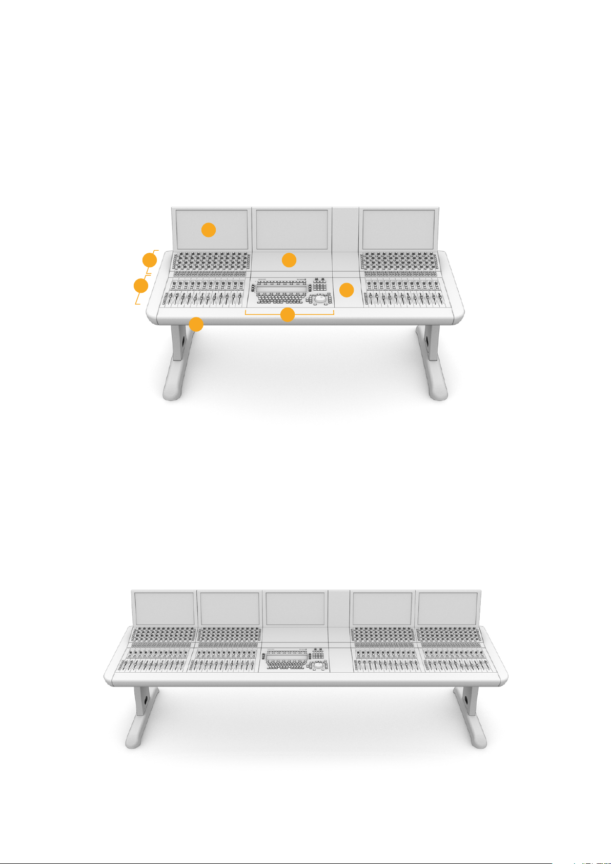
Fairlight Console Components
The Fairlight console is available in 4 configurations that let you build your console to suit
yourproduction requirements. Fairlight modules, for example the Fairlight Console Channel
Control, Fairlight Console Channel Fader, Fairlight Console Audio Editor, and the Fairlight
Console LCD Monitor, are installed into the module slots within the Fairlightconsole chassis.
Fairlight 3 Bay Console
1
2
3
4
1. Fairlight Console LCD Monitor 2. Fairlight Console Channel Control 3. Fairlight Console Channel Fader
4. Fairlight Console chassis, includes legs 5.Fairlight Console Audio Editor
6. Fairlight Console Channel Control Blank 7. Space for your mouse or notes
6
7
5
The illustration above shows a fully assembled Fairlight 3 Bay console. In a typical 3 bay
configuration, the Fairlight Console Channel Control and Fairlight Console Channel Fader
modules are installed on each side of the Fairlight Console Audio Editor. However you can
place modules in any position you prefer, as your Fairlight console is fully customizable.
On a 4 and 5 bay configuration, additional modules can be installed on each side.
Fairlight 5 Bay Console
4Fairlight Console Components
Page 5
Fairlight 2 Bay Console
The 2 bay configuration sets the Fairlight Console Channel Control module and Fairlight
Console Channel Fader module next to the Fairlight Console Audio Editor
NOTE You can arrange the Fairlight modules on either side of the audio editor and
change the position of the mouse area. For example you may be left handed and want to
have the mouse on the left side of the audio editor module. Fairlight modules are mounted
in a module bracket that can be lifted out and repositioned. Keep reading thismanual
for more information on how to install the Fairlight modules into the modulebrackets.
A Fairlight Console Channel Rack Kit is also available from Blackmagic Design resellers
if you need to install additional devices in your console. For example Blackmagic
HyperDeck recorders or SmartScope Duo monitors.
Additionally, you can install Fairlight Console LCD Monitor Blank, Fairlight Console
Channel Control Blank, or Fairlight Console Channel Fader Blank kits.
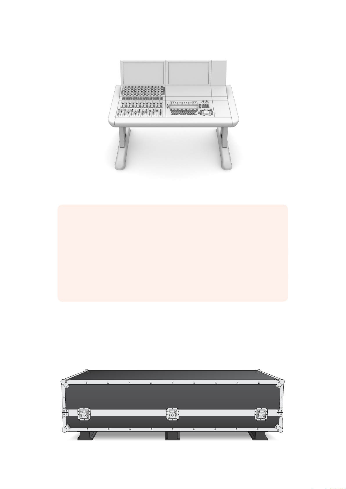
Unpacking and Assembling
Your Fairlight console is shipped in a large, strong and secure road case containing the
FairlightConsole chassis and legs. Each Fairlight module is shipped separately. Refer to the
‘technical specifications’ section of this manual for a complete list of size and weight
measurements foreach Fairlight configuration.
5Unpacking and Assembling
Page 6
After opening your Fairlight console's road case, carefully remove the console chassis and
place it gently onto a solid, stable surface strong enough to support the weight of the
chassis and legs.
NOTE Please note that an empty Fairlight 3 Bay Console weighs 90kg and up to
150kg for a 5 bay console. The console is built strong and is clearly too heavy to be
unpacked by one person. You will need to make sure that all lifting is performed by
4people using the correct lifting techniques, such as bending your knees, keeping a
straight back and lifting with careful, controlled movements.
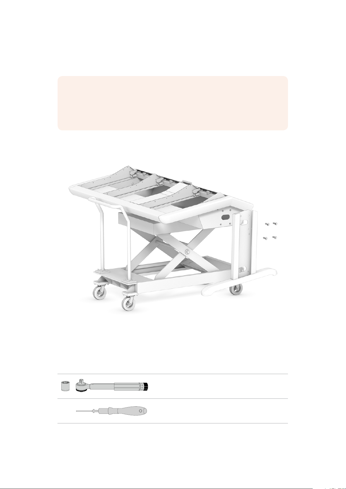
The surface your Fairlight console will be placed onto for assembly needs to be high enough
from the ground to ensure the legs are elevated when attaching to the chassis. Allow for at
least550mm. A scissor lift trolley or similar utility is the perfect solution for assembly.
Alternatively, if assembling the console with two or more people, you can stand the chassis on
its rear panel while attaching the legs and feet. Refer to the next section named 'Alternative
Assembly with Two or More People' for more details.
Tools Required
For assembly you will need the following tools:
1 x Torque wrench with
19mm socket capable of 35 Nm.
1 x Pozidriv 2 torque driver capable
of 0.45 Nm for M3 and M4 screws.
We recommend using torque tools for tightening only, and using a regular wrench or driver
forremoving the screws.
6Unpacking and Assembling
Page 7
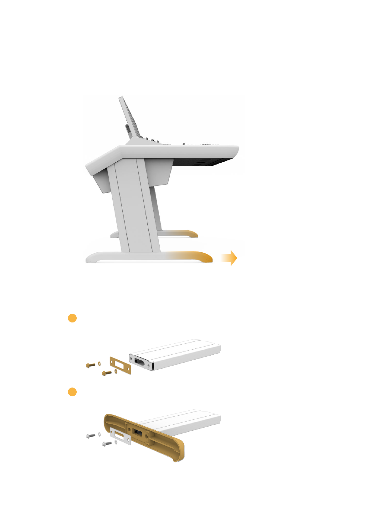
Attaching the Legs to the Console Chassis
The road case contains two legs that attach to each side of the console chassis. However,
before attaching to the chassis, you should first secure the feet to each leg. Each assembled
leg weighs 10 kilograms, so please take care when lifting.
The feet are attached to the console chassis with their length longer
atoneend. Ensure the longer end is facing the front of the console.
To attach the foot to each leg:
1 Lay the leg on its side with the cover panel facing upwards. Remove the two
M12screws fromthe end including the small brace plate.
2 Align the foot to the end of the leg and hold it in place. Make sure the rectangular
cutouts on the bottom of the leg and brace plate are completely aligned.
7Unpacking and Assembling
Page 8
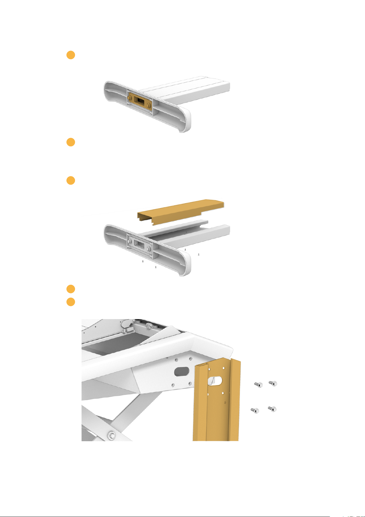
3 Now place the support plate on the bottom of the foot and secure the
foot to the leg using the two M12 screws. Tighten to atorque of 35 Nm.
4 Repeat steps 1 to 3 for the second leg.
To attach the legs to the console chassis:
1 Remove the side cover from each leg by unscrewing the four M3 screws
from the opposite side of the leg using a Pozidriv 2 screwdriver.
2 Remove the four M12 leg fastening screws from each side of the console chassis.
3 Align each leg to the side of the console by mounting it against the
guide pins on the chassis.
8Unpacking and Assembling
Page 9
4 Secure the legs to the chassis with the leg fastening screws and tighten the screws to
atorque of 35 Nm.
The side cover for each leg can be reattached later. Leaving the cover off at this point
of assembly provides access to the inside of the leg for when you are wiring up the
panels inside the console.
5 Carefully lower the console from the support surface and place it on the floor.
Werecommend placing the assembled chassis as close to its intended position as
possible, as once Fairlight modules are installed, the overall weight of the unit will
increase substantially. Ensure there is enough space at the rear of the chassis to
replace the back panel before securing your console into position.
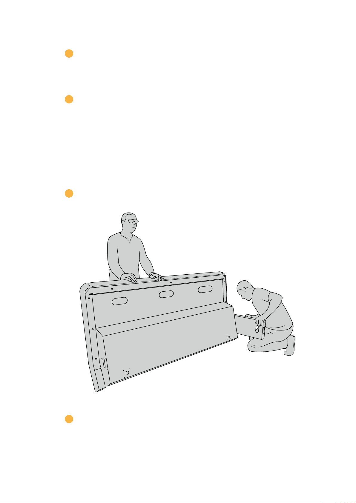
Alternative Assembly with Two or More People
If you don't have access to a scissor lift trolley or similar utility and have someone tohelp you,
you can stand the chassis on its rear panel and attach the legs and feet from this position.
To assemble the legs and feet:
1 After removing the console chassis from its road case, gently lean the chassis onto its
rear panel. Ensure a second person holds the chassis in place so it does not slip.
Lean the console chassis onto its rear panel so the front is facing upwards
2 With the console chassis securely held in place, attach the legs as shown in the
previous section.
9Unpacking and Assembling
Page 10

3 Attach the feet to each leg.
4 Once the legs and feet are attached, lean the chassis onto its feet into its
standing position.
Lean the Fairlight console onto its feet, ready to install the Fairlight panels
With the legs and feet attached to the console chassis, you can now install the
Fairlight panels.
10Unpacking and Assembling
Page 11

Installing the Fairlight Panels
The most common layout Fairlight audio engineers use for mounting the modules is to place the
Fairlight Console Audio Editor directly in front of the operator, the Fairlight Console Channel
Control and Channel Fader modules on each side, and the channel control modules above each
channel fader module. Their respective LCD monitors are installed along the top with the monitor
infill module. The small surface in between the Fairlight modules is for a mouse or trackball.
If you don't have all the modules for a full console, you can fill in the spaces with blank panels
until you are ready to add more modules later. You can add modules any time you like and as
you need them based on your production requirements.
To install the Fairlight modules into the console chassis:
1 Remove the back panel from the chassis by unscrewing the M3 screws using
aPozidriv2 screwdriver, and keep the panel and screws nearby in a safe place.
Removingthe back panel provides better access to the inside of the chassis
wheninstalling the Fairlight modules.
2 Each Fairlight module has its own module bracket you can easily lift and remove
fromthe chassis. This lets you install modules into their brackets on a bench where
thereismore space, then easily mount the assembled brackets into the chassis.
Hold each bracket arm and gently rotate the bracket up from the chassis. The bracket
hinges from the rear, allowing you tofree the bracket from the chassis by pulling it
awayfromthe hinge pin.
11Unpacking and Assembling
Page 12

3 With the module bracket removed from the chassis, place it on a stable surface, ready
forattaching the Fairlight modules. We recommend installing modules starting with the
LCD monitor at the top, the Fairlight Console Channel Control module in the middle,
then the Fairlight Console Channel Fader module closest to the audio operator.
4 Secure each module to the bracket usingthe M4 Pozidriv screws supplied with your
Fairlight module. Tighten to a torque of 1.5 Nm.
5 You can now place the assembled module bracket back into the chassis by
repositioning its rear latchesover the chassis hinge pins and gently lowering the
bracket into place.
NOTE When installing a bracket with Fairlight panel modules attached, we
recommend one person holding thefront edge of the bracket, with a second
supporting the bracket from underneath the chassis as it is lowered into place.
This lets you lower the bracket gently without dropping the edge at the
finalmoment.
After installation, the brackets can be lifted again by pushing from underneath
with one hand, and lifting the front of the bracket with the other. Each bracket
has a bay lift support brace you can swing out from underneath. This lets you
safely prop the bracket away from the chassis when you need to access the
interior for cabling.
12Unpacking and Assembling
Page 13

Lower the support brace by holding the brace handles and rotating
the brace down from the bracket. Allow the feet of the brace to rest
inside and against the front of the chassis so it cannot move.
Attaching the Monitor Infill Module
Inside the road case, you’ll find a small cardboard box. This box contains the LCD monitor infill
module that is installed next to the LCD monitors.
Remove the infill bracket from the chassis following the same procedure used for the other
module brackets.
To attach the infill module:
1 Place the monitor infill module into the neck of the bracket.
2 Secure the inf ill module to the bracket using the supplied M4 Pozidriv screws.
Tighten to a torque of 0.45Nm.
3 Place the bracket back into the chassis.
13Unpacking and Assembling
Page 14

Powering the Modules
Each Fairlight module is powered independently via its own power input. Simply plug each
module into your mains power supply using a standard IEC power cable.
We recommend using five way power boards to distribute power to the Fairlight modules, with
each power board to supply up to five modules only. Ensure the power boards are not daisy
chained and are each independently connected to mains power.
Two chassis earth points are built into the inner sides of the chassis for securing to a building
earth point. After installation, ensure at least one of the chassis earth points is connected to the
building earth point via an appropriately sized and bonded earth wire. With the Fairlight console's
rear cover detached, you can easily access the earth points on each side of the chassis.
Connect power to each Fairlight module via its standard IEC power input
Arranging Cables and Replacing the Leg Side Covers
Your Fairlight console is designed to keep cables tidy. After connecting power cables, you can
bundle them together and guide them through the cable slots on each leg.
Once cables are in place, you can then re-install the leg side covers and tightentheir 4 x M3
Pozidriv screws to a torque of 0.35Nm.
14Unpacking and Assembling
Page 15

Connecting the Fairlight Modules
HDMI
After installing the Fairlight modules and plugging in power, connect each module to the other
using an Ethernet daisy chain. It doesn’t matter which particular unit is connected to the other,
as long asthey are all connected via their Ethernet ports.
If you would like to use an Ethernet switch to connect the modules, this is ok and just place the
Ethernet switch inside the console where there is lots of space. Then you can connect each
panel module to the switch directly.
Below is an example of how you could connect the Fairlight modules in a daisy chain.
Ethernet
CONTROL ROOM STUDIO
Computer
TIP We recommend using 1.2 meter Cat6 Ethernet cables. These will allow you to
liftthe panel brackets after installation without stretching the cables.
Connecting the Fairlight Console to your Computer
Once all the modules in the console are connected together via ethernet, connect one of them
to the computer that will run DaVinci Resolve.
15Unpacking and Assembling
Page 16

Connecting the Computer’s HDMI or SDI Output
The LCD monitor above the Fairlight Audio Editor connects to your computer’s HDMI monitor
output. This lets you monitor DaVinci Resolve’s Fairlight page.
This LCD monitor can also be connected to the SDI output from video playback equipment,
for example a Videohub router or Decklink video output.
You can also bundle the Ethernet and video cables together with the power cables that are
threaded through your console’s legs and feet. This keeps all cables neatly together to and
from your Fairlight console.
Reattaching the Chassis Back Panel
Now that all your Fairlight modules are installed, powered and connected, the final step to
complete the assembly of your console is to reattach the chassis’ back panel.
Secure in place using the M3 Pozidriv screws and tighten to a torque of 0.45 Nm.
This completes the assembly and connection setup for your Fairlight console. You are now
ready to confirm your console is working with DaVinci Resolve.
Configuring the Fairlight Modules
The next step is to configure your Fairlight console for your studio.
There are two Fairlight utilities that are included in the DaVinci Resolve installer. The utilities
arecalled Fairlight Panel Setup and Fairlight Studio Utility.
The full studio version of DaVinci Resolve can be installed from the SD card included
withyourFairlight Console, but we recommend downloading the latest version from the
Blackmagic Design Support Center at www.blackmagicdesign.com/support.
To install DaVinci Resolve, launch the DaVinci Resolve installer and follow the onscreen
prompts. Be sure to select the 'Fairlight Studio Utility' when installing DaVinci Resolve.
16Configuring the Fairlight Modules
Page 17

Fairlight Panel Setup
Fairlight Panel Setup can be connected to the Fairlight module via USB or Ethernet using DHCP.
If you are not using a DHCP server, you can set the network settings to a fixed IP address via
USB. More information for changing network settings is provided later in this manual.
When configuring the Fairlight console for your studio, the first step is to name each module
using the Fairlight Panel Setup utility. This lets you easily identifiy each panel module by clicking
on the 'identify me' checkbox.
To name each module:
1 Launch the Fairlight Panel Setup utility.
The currently selected module will be visible on the setup
utility home screen. Navigate to each installed unit by clicking
on the arrows on each side of the home screen
2 Select a module on the home screen and click on the settings icon. You can also click
on the module's image to open the settings window.
3 Click on the 'configure' tab. Under 'device name' you will see a 'label' text box.
Changethe name in the text box and click 'save'. You can visually identify each module
installed in your console by clicking on the 'identify' checkbox. This will illuminate
features on the module.
17Configuring the Fairlight Modules
Page 18

Assign a custom name for each Fairlight module using the
'configure' settings in the Fairlight Panel Setup utility
Studio Name
Name the studio this Fairlight module will be assigned to.
Network Settings
Refer to the ‘Changing Network Settings’ section for information on manually changing
these settings.
Brightness
Changes the brightness of the Fairlight module’s LCDs, or the brightness of the Fairlight
Console LCD Monitor. Drag the slider left or right to decrease or increase the brightness.
Display Source
Each Fairlight Console LCD Monitor can be set as a data display or video monitor. This means
the monitor can be set to display the Fairlight page connected via Ethernet, or a video image if
there is a signal connected to the monitor's HDMI or SDI video input.
Data display – Displays the Fairlight page.
Video monitor – Displays the SDI or HDMI video input.
If a video signal is connected to either the HDMI or SDI input, the monitor will automatically
detect which input is being used. However, if both inputs have a video signal connected, you
can manually set the desired input.
18Configuring the Fairlight Modules
Page 19

3D LUT
When monitoring a video input, you can load a 3D LUT. For example, a 3D LUT can be used to
change the color space of the input video from a flat look to Rec 709, or you may want to load a
preset 'look' designed during post production. You can also use this 3D LUT to fine tune the
display on each of your Fairlight console's LCD monitors if the color reproduction between them
is a little different.
To load a 3D LUT:
1 In the 'load LUT' setting, click on the 'load' button.
2 Navigate to the folder where your LUTs are stored and click on the desired
.cube LUT file.
3 Click 'open'.
The 3D LUT will now be applied to your video source. If you want to disable the LUT, click on
the 'clear' button.
Changing Network Settings
If you need to change the network settings for each module manually, you can change the
settings in the 'configure' tab of the Fairlight Panel Setup utility. When changing network
settings, you will need to connect the panel to your computer via USB.
To change network settings:
1 Open the Fairlight Panel Setup utility. Click on the settings icon, or the Fairlight module
displayed on the home page to open the settings for that module.
2 Click on the 'configure' tab.
3 Change the 'IP Setting' from DHCP to 'Static IP'.
4 In the 'network settings', type a new address into the IP address, subnet mask, and
gateway text boxes.
When the IP address is set correctly, the module will be accessible on your network.
Repeat the same process for each Fairlight panel via USB.
Updating your Fairlight Modules' Internal Software
It’s a good idea to regularly check our website for new software updates.
When a new version of DaVInci Resolve is installed, it may also install updates for your
Fairlight console. To check, open the Fairlight Panel Setup utility and if there are new
updates you will see an 'update' button on the home screen for each module. Simply
click on the 'update' button and follow the prompts to update each module.
With all the setup settings complete, you can now close the Fairlight Panel Setup utility.
19Configuring the Fairlight Modules
Page 20

Fairlight Studio Utility
After setting up your Fairlight modules in the setup utility, assign each module to your
FairlightConsole using the Fairlight Studio Utility. This configures your console as a studio,
telling DaVinci Resolve exactly where each panel is in your Fairlight console so the Fairlight
page can control them all properly and display their controls on the appropriate LCD monitors.
The Fairlight Desktop Audio Editor does not need to be added to a studio configuration to be
selected by DaVinci Resolve. If you have only a Desktop Audio Editor in your studio, go to the
next section, ‘Selecting your Fairlight Console in DaVinci Resolve’, and follow the instructions
there to select the editor in DaVinci Resolve.
To set up a Fairlight Console for each studio:
1 Launch the Fairlight Studio Utility.
2 Select the number of bays in your Fairlight console and click 'next'. This will open a
configuration screen where modules are assigned to the corresponding chassis slots
in each bay.
Select the number of bays in your Fairlight console
3 In the configuration screen, click on the top left slot to assign a Fairlight Console
LCDMonitor. From the list of modules, select the desired monitor for the corresponding
slot by clicking on its icon.
Click on the top left slot to assign the corresponding LCD monitor
20Configuring the Fairlight Modules
Page 21

Each module can be identified by the custom name you entered when labeling the
modules. You can also click on the light bulb icon for each module to visually identify it.
When clicking on the light bulb, features will illuminate on the relevant module.
Click on the light bulb icon to identify each module in your Fairlight console
4 Click 'add'.
The monitor will be assigned to the top left slot on your Fairlight console. You can now
follow the same procedure to assign all the other panels to the corresponding
positionsin the configuration utility. If you select the wrong module by mistake, all you
need to do is click on the module in the group to reveal its options and then click on
the 'X' icon to remove it.
As you configure each module, you can confirm it corresponds to the correct position
in the console by clicking on the module in the group to reveal its options and then
clicking on the light bulb icon.
Your Fairlight console is now conf igured as a studio and you can change the name of
the studio by clicking in the 'untitled studio' text box, typing a new name, and pressing
the 'return' key to confirm. This makes it easier to identify each studio if you have
multiple studios installed in your facility.
Rename the newly configured studio by clicking in the studio name,
typinganew one, then pressing the 'return' key to confirm the change
21Configuring the Fairlight Modules
Page 22

Selecting your Fairlight Console in DaVinci Resolve
The next step is to select your Fairlight console in DaVinci Resolve's preferences.
1 Launch DaVinci Resolve.
2 In the menu bar at the top of the screen, select DaVinci Resolve/Preferences.
3 In the ‘Control Panels’ menu, you’ll notice an option for ‘Audio Console’ and a drop
down menu where you can select your console for Fairlight. Click on the drop down
menu and select the studio name for your console. If you have a standalone Fairlight
Desktop Audio Editor, you can also select it here.
4 Click ‘Save’.
The preferences window will close and a new message will appear asking you to restart
DaVinci Resolve. Simply restart DaVinci Resolve and your console will now be selected for
control using the Fairlight page.
22Configuring the Fairlight Modules
Page 23

Technical Specifications
Fairlight Road Case Dimensions
All contents included
2 bay Console
Road Case
Width = 1353 mm
Height = 552 mm
Depth = 1101 mm
Weight = 180 kg
3 bay Console
Road Case
Width = 1844 mm
Height = 552 mm
Depth = 1101 mm
Weight = 205 kg
4 bay Console
Road Case
Width = 2825 mm
Height = 552 mm
Depth = 1101 mm
Weight = 280 kg
Fairlight Console Dimensions and Weight
5 bay Console
Road Case
Width = 2825 mm
Height = 552 mm
Depth = 1101 mm
Weight = 300 kg
2 bay Console
Width = 1295 mm
Height = 1047 mm
Depth = 982 mm
Weight
Empty chassis including
legs and monitor infill
panel = 90 kg
Fully assembled = 120 kg
3 bay Console
Width = 1788 mm
Height = 1047 mm
Depth = 982 mm
Weight
Empty chassis including
legs and monitor infill
panel = 110 kg
Fully assembled = 157 kg
4 bay Console
Width = 2277 mm
Height = 1047 mm
Depth = 982 mm
Weight
Empty chassis including
legs and monitor infill
panel = 130 kg
Fully assembled = 195 kg
5 bay Console
Width = 2769 mm
Height = 1047 mm
Depth = 982 mm
Weight
Empty chassis including
legs and monitor infill
panel = 150 kg
Fully assembled = 232 kg
23Technical Specifications
Page 24

Fairlight Panels Dimensions and Weight
SOLO
MUTE
CALL AUTO
10 •
5 •
0 •
5 •
10 •
15 •
20 •
30 •
40 •
50 •
70 •
100 •
• 10
• 5
• 0
• 5
• 10
• 15
• 20
• 30
• 40
• 50
• 70
• 100
SOLO
MUTE
CALL AUTO
10 •
5 •
0 •
5 •
10 •
15 •
20 •
30 •
40 •
50 •
70 •
100 •
• 10
• 5
• 0
• 5
• 10
• 15
• 20
• 30
• 40
• 50
• 70
• 100
SOLO
MUTE
CALL AUTO
10 •
5 •
0 •
5 •
10 •
15 •
20 •
30 •
40 •
50 •
70 •
100 •
• 10
• 5
• 0
• 5
• 10
• 15
• 20
• 30
• 40
• 50
• 70
• 100
SOLO
MUTE
CALL AUTO
10 •
5 •
0 •
5 •
10 •
15 •
20 •
30 •
40 •
50 •
70 •
100 •
• 10
• 5
• 0
• 5
• 10
• 15
• 20
• 30
• 40
• 50
• 70
• 100
SOLO
MUTE
CALL AUTO
10 •
5 •
0 •
5 •
10 •
15 •
20 •
30 •
40 •
50 •
70 •
100 •
• 10
• 5
• 0
• 5
• 10
• 15
• 20
• 30
• 40
• 50
• 70
• 100
SOLO
MUTE
CALL AUTO
10 •
5 •
0 •
5 •
10 •
15 •
20 •
30 •
40 •
50 •
70 •
100 •
• 10
• 5
• 0
• 5
• 10
• 15
• 20
• 30
• 40
• 50
• 70
• 100
SOLO
MUTE
CALL AUTO
10 •
5 •
0 •
5 •
10 •
15 •
20 •
30 •
40 •
50 •
70 •
100 •
• 10
• 5
• 0
• 5
• 10
• 15
• 20
• 30
• 40
• 50
• 70
• 100
SOLO
MUTE
CALL AUTO
10 •
5 •
0 •
5 •
10 •
15 •
20 •
30 •
40 •
50 •
70 •
100 •
• 10
• 5
• 0
• 5
• 10
• 15
• 20
• 30
• 40
• 50
• 70
• 100
SOLO
MUTE
CALL AUTO
10 •
5 •
0 •
5 •
10 •
15 •
20 •
30 •
40 •
50 •
70 •
100 •
• 10
• 5
• 0
• 5
• 10
• 15
• 20
• 30
• 40
• 50
• 70
• 100
SOLO
MUTE
CALL AUTO
10 •
5 •
0 •
5 •
10 •
15 •
20 •
30 •
40 •
50 •
70 •
100 •
• 10
• 5
• 0
• 5
• 10
• 15
• 20
• 30
• 40
• 50
• 70
• 100
SOLO
MUTE
CALL AUTO
10 •
5 •
0 •
5 •
10 •
15 •
20 •
30 •
40 •
50 •
70 •
100 •
• 10
• 5
• 0
• 5
• 10
• 15
• 20
• 30
• 40
• 50
• 70
• 100
SOLO
MUTE
CALL AUTO
10 •
5 •
0 •
5 •
10 •
15 •
20 •
30 •
40 •
50 •
70 •
100 •
• 10
• 5
• 0
• 5
• 10
• 15
• 20
• 30
• 40
• 50
• 70
• 100
BLUE
BANK
FLIP
1
POT
2
FDR
3
MAP
4
BUS
5
MSET
6
LOCK
MACRO1MACRO2MACRO3MACRO4MACRO5MACRO6MACRO7MACRO8MACRO9MACRO10MACRO11MACRO12MACRO13MACRO14MACRO
15
Audio
1
R S M
Audio
2
R S M
Audio
3
R S M
Audio
4
R S M
Audio
5
R S M
Audio
6
R S M
Audio
7
R S M
Audio
8
R S M
Audio
9
R S M
Audio
10
R S M
Audio
11
R S M
Audio
12
R S M
All
Tracks
Bank
Bank
LEFT
NUDGE
RIGHT
NUDGE
LEVEL
CUP
PAN EQ DYN AUX PLUGIN
SETUP REC MON
HEAD
TRIM
TAIL
TRIM
HEAD
CUT
TAIL
CUT
CLIP
CUT
CLIP
COPY
TAIL
COPY
IN
FADE
OUT
FADE
HEAD
COPY
EDITORMIXER MACRO
SPLIT DEL
SHTL
POSN
PLAY
JOG
JUMP
JUMP
UNDO
REDO
ENTER ZOOM
+ 0
GO
TO
–
1 2
3 :
4 5
6 BAR
7 8
9 CLEAR
DIM MUTE
TALK MUTE
CONTROL ROOM STUDIO
ESC
BLUE
CONTROL ROOM STUDIO
Fairlight Console LCD Monitor
Width = 489.6 mm
Height = 335.4 mm
Depth = 58.7 mm
Weight = 4.4 kg
BLUE
MSTR
U1
PLUG
U2
CHAN
U3
ENAB
COPY
CURVE
SPILL
ALT
SHOW
INS
SHOW
INS
SHOW
INS
SHOW
INS
SHOW
INS
SHOW
INS
SHOW
INS
SHOW
INS
SHOW
INS
SHOW
PLUGS
IN
PLUGS
IN
PLUGS
IN
PLUGS
IN
PLUGS
IN
PLUGS
IN
PLUGS
AUTO
SOLO
AUTO
SOLO
AUTO
SOLO
AUTO
SAFE
SAFE
ARM SEL
SOLO
SAFE
SAFE
SAFE
SAFE
SAFE
SAFE
ARM SEL
ARM SEL
ARM SEL
IN
AUTO
SOLO
AUTO
SOLO
AUTO
SOLO
SAFE
SAFE
SAFE
SAFE
SAFE
SAFE
ARM SEL
ARM SEL
ARM SEL
INS
PLUGS
IN
PLUGS
IN
PLUGS
IN
AUTO
SOLO
AUTO
SOLO
AUTO
SOLO
SAFE
SAFE
SAFE
SAFE
SAFE
SAFE
ARM SEL
ARM SEL
ARM SEL
Fairlight Console Channel Control
Width = 489.6 mm
Height = 229.3 mm
Depth = 66.5 mm
Weight = 4.4 kg
BLUE
PAN
PATH
EQ
FLIT
AUX
AUX
COMP
U1
LIM
U2
EXP
U3
ALT
SHOW
INS
SHOW
INS
PLUGS
IN
PLUGS
IN
AUTO
SOLO
AUTO
SOLO
SAFE
SAFE
SAFE
SAFE
ARM SEL
ARM SEL
Fairlight Console Channel Fader
Width = 489.6 mm
Height = 329.9 mm
Depth = 66.6 mm
Weight = 8.45 kg
Power Consumption
Input Power
100-240VAC, 1.7A, 50-60Hz
Operating Temperature
Fairlight Console Audio Editor,
Fader and Channel Control panels
0 to 40°C or 40 to 104°F
Fairlight Console LCD Monitor
0 to 35°C or 40 to 95°F
Fairlight Console Audio Editor
Width = 489.6 mm
Height = 329.9 mm
Depth = 69 mm
Weight = 8.5 kg
24Technical Specifications
Page 25

Help
The fastest way to obtain help is to go to the Blackmagic Design online support pages and
check the latest support material available for your Fairlight Console.
Blackmagic Design Online Support Pages
The latest manual, software and support notes can be found at the Blackmagic Design support
center at www.blackmagicdesign.com/support.
Contacting Blackmagic Design Support
If you can’t find the help you need in our support material, please use the ‘Send us an email’
button on the support page to email a support request. Alternatively, click on the ‘Find your
local support team’ button on the support page and call your nearest Blackmagic Design
support office.
Checking the Software Version Currently Installed
To check which version of Fairlight Console software is installed on your computer, open the
Fairlight Console Components Setup utility and click on the ‘about’ tab. The current version
number will be displayed.
How to Get the Latest Software Updates
After checking the version of Blackmagic Fairlight software installed on your computer, please
visit the Blackmagic Design support center at www.blackmagicdesign.com/support to check for
the latest updates. While it is usually a good idea to run the latest updates, it is wise to avoid
updating any software if you are in the middle of an important project.
25Help
Page 26

Regulatory Notices
Disposal of waste of electrical and electronic equipment within the European union.
The symbol on the product indicates that this equipment must not be disposed of with
other waste materials. In order to dispose of your waste equipment, it must be handed
over to a designated collection point for recycling. The separate collection and recycling
of your waste equipment at the time of disposal will help conserve natural resources and
ensure that it is recycled in a manner that protects human health and the environment. For
more information about where you can drop off your waste equipment for recycling, please
contact your local city recycling office or the dealer from whom you purchased the product.
This equipment has been tested and found to comply with the limits for a Class A digital
device, pursuant to Part 15 of the FCC rules. These limits are designed to provide
reasonable protection against harmful interference when the equipment is operated in a
commercial environment. This equipment generates, uses, and can radiate radio frequency
energy and, if not installed and used in accordance with the instructions, may cause harmful
interference to radio communications. Operation of this product in a residential area is
likely to cause harmful interference, in which case the user will be required to correct the
interference at personal expense.
Operation is subject to the following two conditions:
1 This device may not cause harmful interference.
2 This device must accept any interference received, including interference that may cause
undesired operation.
Connection to HDMI interfaces must be made with high quality shielded HDMI cables.
26Regulatory Notices
Page 27

Safety Information
Weight Warning
The Fairlight Console has considerable weight even when empty. For example, a three bay
console weighs up to 110 kg empty, and 157 kg fully assembled. You should always move a
Fairlight console with at least 4 people using safe lif ting procedures, such as keeping the
back straight, bending the knees and lifting with careful, controlled movements.
Electrical Warning Notice and Disclaimer
For installations involving the fitting of more than three Fairlight modules, additional
earthing requirements must be fitted before connecting the supply.
It is recommended that any metallic equipment enclosures are securely connected to
the metallic console frame. The metallic console frame must be earthed according to the
appropriate electrical standards that apply at the installation location. Earth posts are
welded internally at both ends of the console frame for connecting earth wires from the
console frame to the building earth point. Either of these posts can be used and they are
marked with the following label.
Fastening screws and associated washer par ts used to connect enclosures to the console
frame must ensure a reliable and low resistance electrical contact between the enclosures
and console frame.
The electrical mains wiring from the building supply point to the console and to all
equipment located inside the console is the customer’s responsibility.
Blackmagic Design recommends appointing a qualif ied and licenced electrician to install,
test and commission this wiring system. Safety requirements should be independently
assessed, certified and verified. For example, due consideration of the distribution cable
and wire types, sizes, ratings, insulation, armouring, screening, strain relief, protective
conduits and fixture methods would need to be addressed and calculations made to take
into account the maximum electrical load.
Blackmagic Design does not accept responsibility for the safety, reliability, damage or
personal injury caused to, or by, any third-party equipment fitted into the console.
From the building supply and earthing point, the correct wiring, electrical isolation,
switching, fusing and protective devices, such as earth leakage breakers, would need to
be located properly, labelled and regularly tested.
Earth continuity tests, that is earth resistance tests at high currents, would be necessary
during and regularly after installation to comply with the relevant electrical regulations. In
some cases, lightning protection and/or surge suppression may need to be installed.
To reduce the risk of electric shock, do not expose this equipment to dripping or splashing.
Ensure that adequate ventilation is provided around the product and is not restricted.
Use only at altitudes not more than 2000m above sea level.
No operator serviceable parts inside. Refer servicing to your local Blackmagic Design
service centre.
27Safety Information
Page 28

Warranty
12 Month Limited Warranty
Blackmagic Design warrants that this product will be free from defects in materials and workmanship
for a period of 12 months from the date of purchase. If a product proves to be defective during this
warranty period, Blackmagic Design, at its option, either will repair the defective product without
charge for parts and labor, or will provide a replacement in exchange for the defective product.
In order to obtain service under this warranty, you the Customer, must notify Blackmagic Design
of the defect before the expiration of the warranty period and make suitable arrangements for the
performance of service. The Customer shall be responsible for packaging and shipping the
defective product to a designated service center nominated by Blackmagic Design, with shipping
charges pre paid. Customer shall be responsible for paying all shipping charges, insurance, duties,
taxes, and any other charges for products returned to us for any reason.
This warranty shall not apply to any defect, failure or damage caused by improper use or improper
or inadequate maintenance and care. Blackmagic Design shall not be obliged under this warranty:
a) to repair damage resulting from attempts by personnel other than Blackmagic Design
representatives to install, repair or service the product, b) to repair damage resulting from improper
installation, use or connection to incompatible equipment, c) to repair any damage or malfunction
caused by the use of non Blackmagic Design parts or supplies, or d) to service a product that has
been modif ied or integrated with other products when the effect of such a modif ication or integration
increases the time or difficulty of servicing the product.
THIS WARRANTY IS GIVEN BY BLACKMAGIC DESIGN IN LIEU OF ANY OTHER WARRANTIES,
EXPRESS OR IMPLIED. BLACKMAGIC DESIGN AND ITS VENDORS DISCLAIM ANY IMPLIED
WARRANTIES OF MERCHANTABILITY OR FITNESS FOR A PARTICULAR PURPOSE. BLACKMAGIC
DESIGN’S RESPONSIBILITY TO REPAIR OR REPLACE DEFECTIVE PRODUCTS DURING THE
WARRANTY PERIOD IS THE WHOLE AND EXCLUSIVE REMEDY PROVIDED TO THE CUSTOMER.
BLACKMAGIC DESIGN WILL NOT BE LIABLE FOR ANY INDIRECT, SPECIAL, INCIDENTAL OR
CONSEQUENTIAL DAMAGES IRRESPECTIVE OF WHETHER BLACKMAGIC DESIGN OR THE
VENDOR HAS ADVANCE NOTICE OF THE POSSIBILITY OF SUCH DAMAGES. BLACKMAGIC
DESIGN IS NOT LIABLE FOR ANY ILLEGAL USE OF EQUIPMENT BY CUSTOMER. BLACKMAGIC
IS NOT LIABLE FOR ANY DAMAGES RESULTING FROM USE OF THIS PRODUCT. USER OPERATES
THIS PRODUCT AT OWN RISK.
© Copyright 2019 Blackmagic Design. All rights reserved. ‘Blackmagic Design’, ‘Cintel’, ‘DeckLink’, ‘DaVinci Resolve’ are registered
trademarks in the US and other countries. All other company and product names may be trademarks of the respective companies
with which they are associated.
28Warranty
 Loading...