

Page 1

Installation and Operation Manual
Desktop
Video
DeckLink, UltraStudio, Intensity
October 2017
English,
Español, 中文, 한국어
日本語, Français, Deutsch,
and
Русский.
Page 2

Languages
To go directly to your preferred language, simply click on the hyperlinks listed in the
contents below.
English 3
日本語
74
Français 146
Español 290
中文
한국어
Русский
362
434
506
Page 3

Welcome
We hope you share our dream for the television industry to become a truly creative
industry by allowing anyone to have access to the highest quality video.
English
Previously high end television and post production required investment in millions of
dollars of hardware, however with Blackmagic Design video hardware, even Ultra HD
60p is now easily affordable. We hope you get years of use from your new UltraStudio,
DeckLink or Intensity and have fun working with some of the world’s hottest television
and design software!
This instruction manual should contain all the information you’ll need on installing your
Blackmagic Design video hardware. If you’re installing a PCI Express card, it’s always a
good idea to ask a technical assistant for help if you have not installed hardware cards
into computers before. As Blackmagic Design video hardware uses uncompressed video
and the data rates are quite high, you’ll need fast disk storage and a high end computer.
We think it should take you approximately 10 minutes to complete installation. Before
youinstall Blackmagic Design video hardware, please check our website at
www.blackmagicdesign.com and click the support page to download the latest
updates to this manual and Desktop Video driver software. Lastly, please register your
Blackmagic Design video hardware when downloading software updates. We would
love to keep you updated on new software updates and new features. Perhaps you can
even send us your latest show reel of work completed on your Blackmagic Design video
hardware and any suggestions for improvements to the software. We are constantly
working on new features and improvements, so we would love to hear from you!
Grant Petty
CEO Blackmagic Design
Page 4

Contents
Desktop Video
Getting Started 5
Introduction to Desktop Video 5
System Requirements 5
Connecting Power 5
Connecting Video Hardware 6
Installing the Desktop Video Software 10
Applications, Plugins and Drivers 10
Mac OS Installation 10
Windows Installation 11
Linux Installation 12
Capturing and Playing Back Video 13
Blackmagic Desktop Video Utility 15
Introducing Blackmagic
Desktop Video Utility 15
Video Settings 16
Connector Mapping for
DeckLink Quad 2 20
Audio Settings 21
Conversions Settings 23
About 25
Teranex Mini Smart Panel 26
Attaching a Teranex Mini Smart Panel 26
Smart Panel Features 27
Teranex Mini Rack Shelf 27
Using your Favorite
3rdPartySoftware 30
Adobe After Eects CC 30
Adobe Photoshop CC 32
Adobe Premiere Pro CC 33
Final Cut Pro X 38
Avid Media Composer 40
Autodesk Smoke Extension 1 46
Blackmagic Media Express 52
What is Blackmagic Media Express? 52
Capturing Video and Audio Files 52
Playing back Video and Audio Files 57
Browsing Media 59
Editing Video and Audio Files to Tape 62
Capturing H.265 Video 63
H.265 Hardware Encoder 65
Capturing H.265 Video with
UltraStudio 4K Extreme 65
Blackmagic Disk Speed Test 67
Removing the Mezzanine Card
fromDeckLink 4K Extreme 12G 69
Help 70
Developer Information 71
DaVinci Resolve 28
Live Grading with DaVinci Resolve 28
Editing with DaVinci Resolve 29
Regulatory Notices
andSafetyInformation 72
Warranty 73
Contents
Page 5
Getting Started
Introduction to Desktop Video
This manual takes you through computer system requirements and installation instructions for
Blackmagic Design’s Desktop Video hardware and software, and how to use them with your
favorite third party software.
The software includes drivers, plugins and applications like the Blackmagic Desktop Video
Utility, and Blackmagic Media Express for fast capture and playback. Blackmagic Desktop Video
software works in conjunction with your UltraStudio, DeckLink, Intensity or Teranex hardware.
System Requirements
Your computer requires at least 4GB of RAM to efficiently process video.
Mac OS
Blackmagic Desktop Video software runs on the latest El Capitan and Sierra versions
of Mac OS.
Windows
Desktop Video runs exclusively on 64-bit versions of Windows 7, 8 and 10 with the latest
service pack installed.
Linux
Desktop Video runs on 32-bit and 64-bit x86 computers running Linux 2.6.23 or higher. Please
refer to the release notes for the latest list of supported Linux distributions, package formats
and software dependencies.
Connecting Power
If your Desktop Video hardware includes an external power supply, simply connect it to the unit
and switch on the power.
55Getting Started
Page 6
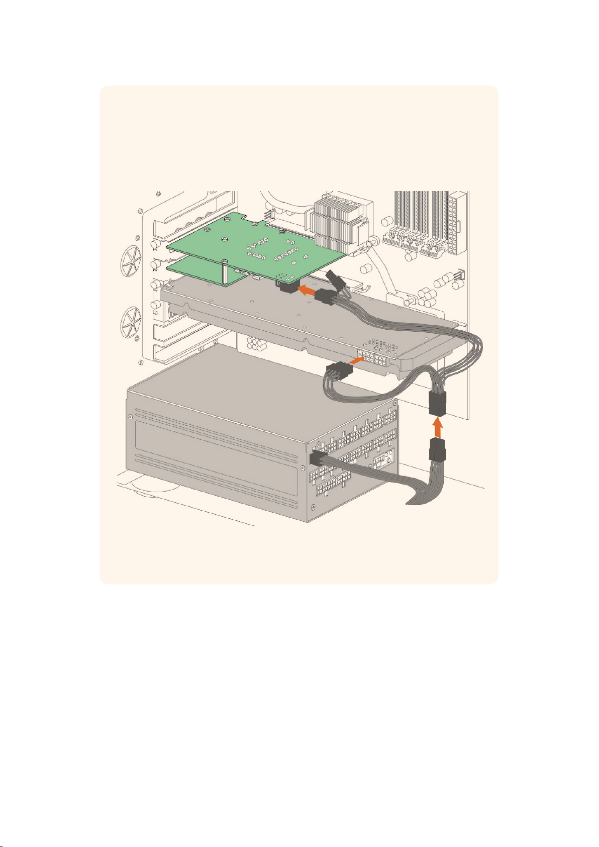
TIP DeckLink 4K Extreme 12G can also be connected to additional power using the
power adapter cable included with the card. DeckLink 4K Extreme 12G is very
powerfuland we are always looking for ways to provide additional features, such as
mezzanine cards for expanded connectivity. For this purpose, we have included a
power adapter cable so you can plug in additional power if future hardware expansion
on your DeckLink card draws more power than your computer’s PCIe slot can provide.
If you need to supply external power to your DeckLink 4K Extreme 12G you
can easily use the supplied power adapter cable. Simply disconnect the
power from your graphics card and plug it into the adapter cable. The plug will
only connect to one end so there’s no way to connect it incorrectly.
Connecting Video Hardware
There are three types of connectors your Blackmagic Desktop Video hardware may use
toconnect to your computer depending on your model. These connection types include
Thunderbolt, USB 3.0, or PCIe.
Connecting via Thunderbolt
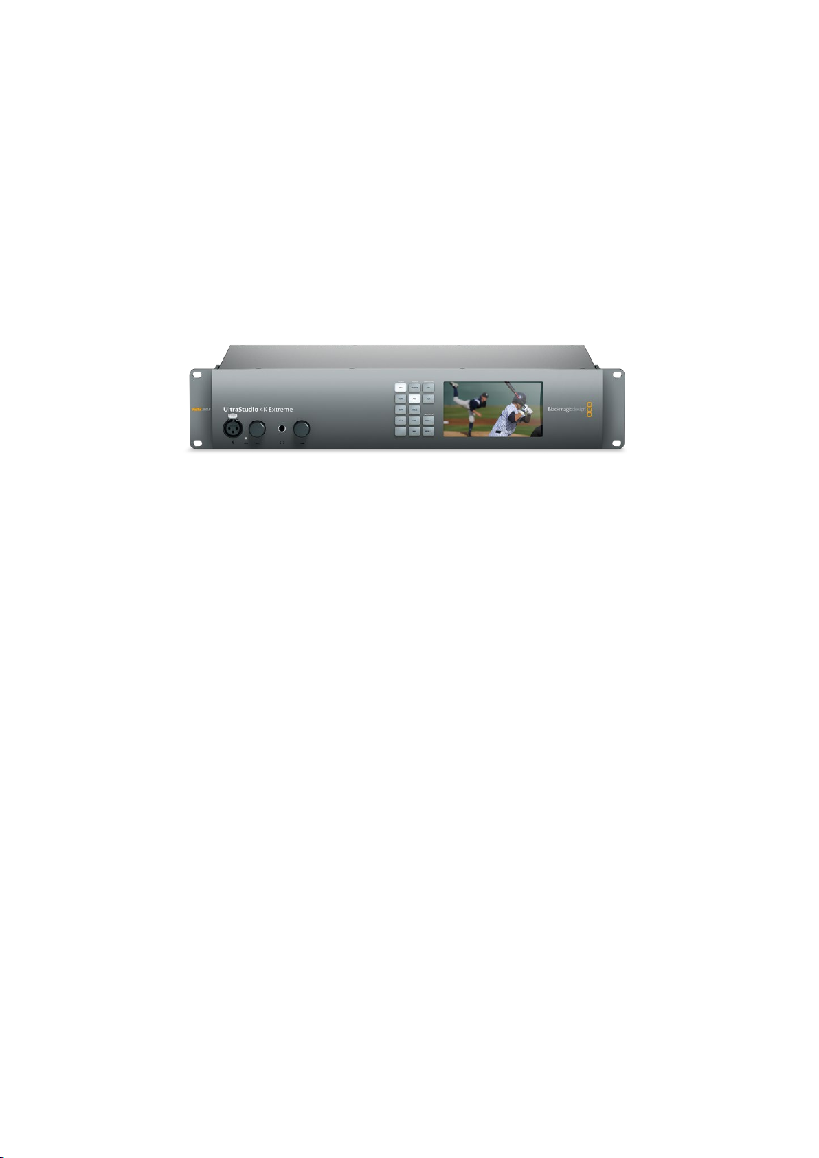
Blackmagic UltraStudio 4K and UltraStudio 4K Extreme feature two Thunderbolt 2™ ports so
ifyour computer only has a single Thunderbolt port, you can use the additional port to attach a
RAID or other device.
66Getting Started
Page 7
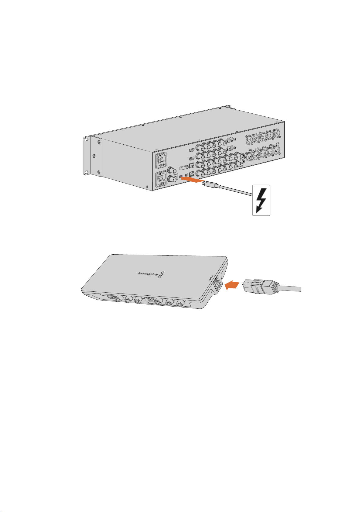
Blackmagic UltraStudio 4K Extreme 3 has two Thunderbolt 3 ports and UltraStudio HD Mini has
HDMI IN
Y IN
Pb IN
Pr IN
S-VIDEO IN
VIDEO IN
L
AUDIO IN
AUDI O O UT
VIDE O O UT
S-VI DEO O UT
Pr O UT
Pb O UT
Y OU T
HDMI OU T
R
one Thunderbolt 3 port, for up to 40Gb/s data speeds. When connecting via Thunderbolt 3,
connect your Blackmagic Desktop Video hardware directly to the Thunderbolt 3 port on your
computer using a Thunderbolt 3 cable. Connecting to a Thunderbolt 2 port on your computer
via a Thunderbolt 3 to Thunderbolt 2 adapter is not supported on bus-powered products like
UltraStudio HD Mini.
Make sure your computer is Thunderbolt 3 compatible by looking for the
Thunderbolt icon near its USB-C connector, as shown on the right.
Connecting via USB 3.0
Connect a SuperSpeed USB 3.0 cable into the USB 3.0 port on the unit. Plugthe other end of
the cable into your computer’s USB 3.0 port.
Connecting a SuperSpeed USB 3.0 cable to Intensity Shuttle
Connecting via PCIe
Blackmagic Design PCIe cards plug into a PCIe slot in your computer. Check the information
printed on your card’s box to determine the number of PCIe lanes your card requires.
Forexample, depending on your PCIe card, it will require a x1, x4 or x8 PCIe slot.
It’s worth noting that you can insert PCIe cards into higher capacity slots than they require.
Forexample, a x4 lane PCIe card can be inserted into a x16 lane PCIe slot, though not the other
way around.
If you can’t find the information you need on the box, you can find the number of lanes
yourcard requires, plus other helpful information about your card, in the tech specs at
www.blackmagicdesign.com/products
77Getting Started
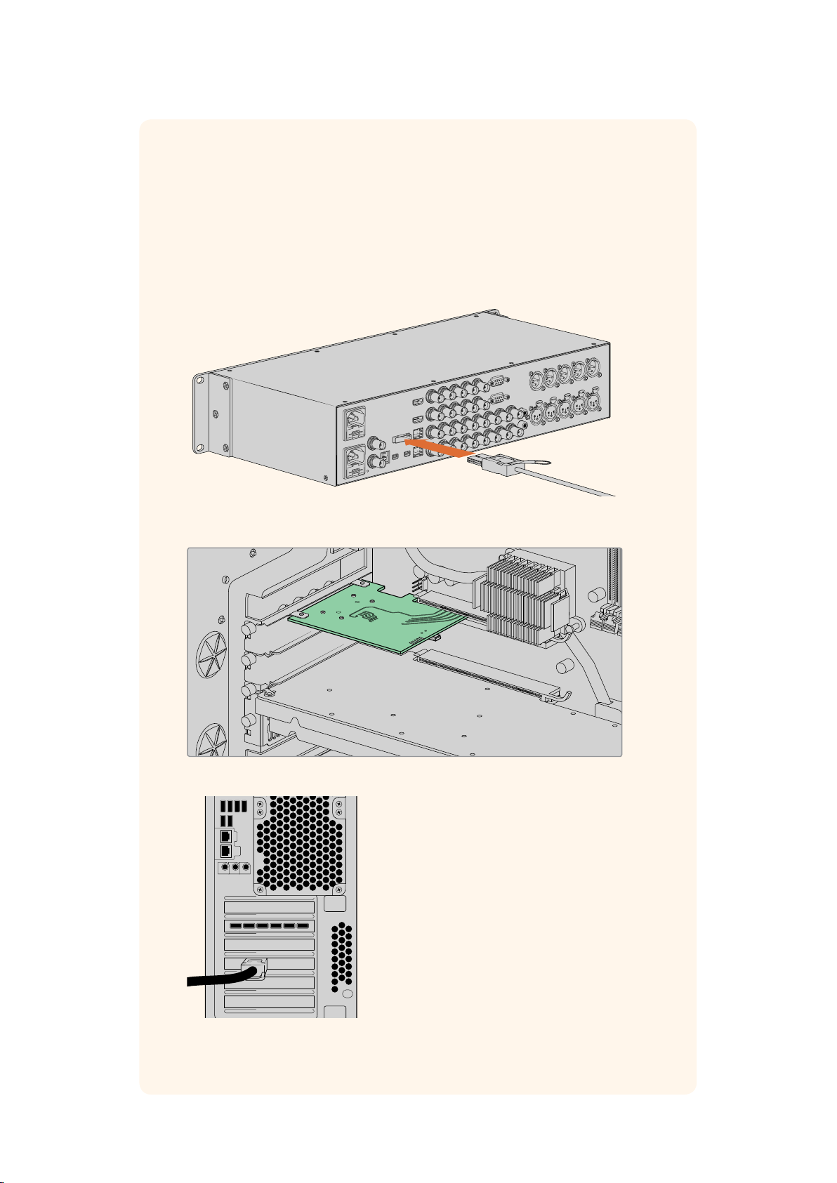
Page 8
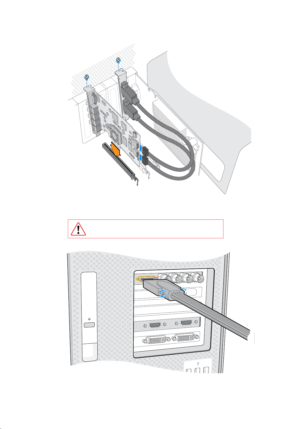
Install a Blackmagic Design PCIe card in a spare PCIe slot. If your card
includes an HDMI bracket, it can be installed in any spare PCIe mount and
connects to the rear of the card with the supplied HDMI cables.
Please be careful when installing your DeckLink PCIe card
toavoiddamaging delicate components on the card.
If your card includes a breakout cable, simply plug it into your card’s breakout cable connector.
88Getting Started
Page 9
Connecting UltraStudio 4K Extreme via PCIe
UltraStudio 4K Extreme and UltraStudio 4K Extreme 3 can also connect to your
computer via PCIe using a PCIe adapter card and cable. Both UltraStudio 4K Extreme
and UltraStudio 4K Extreme 3 need to be connected to a PCIe Gen 2 slot in your
computer. The Blackmagic PCIe Cable Kit contains a PCIe cable and the PCIe adapter
card and is available from your nearest Blackmagic Design reseller.
For the original UltraStudio 4K Extreme, you can use either the Blackmagic PCIe Cable
Kit, or purchase a standard PCIe adapter card from your nearest computer store.
UltraStudio 4K Extreme features a PCIe port for connection to an
external PCIe adapter card that is installed in your computer
The PCIe adapter card is inserted into a PCIe Gen 2 slot inside your computer
Connect the other end of the PCIe cable to the
PCIe port located at the back of your computer
99Getting Started
Page 10

Installing the Desktop Video Software
Applications, Plugins and Drivers
The Blackmagic Design Desktop Video software includes all the drivers, plugins and
applications needed to use your Desktop Video hardware. Below is a list that shows all the
software items that are installed on your computer.
Mac OS Windows Linux
Blackmagic Desktop
Video drivers
Blackmagic Desktop
Video Utility
Blackmagic Design LiveKey Blackmagic Design LiveKey Blackmagic Media Express
Blackmagic Media Express Blackmagic Media Express Blackmagic AVI codecs
Blackmagic QuickTime™ codecs
Blackmagic Disk Speed Test Blackmagic Disk Speed Test –
Adobe Premiere Pro CC,
AfterEffects CC, PhotoshopCC
presets and plug-ins
Final Cut Pro X plug-ins – –
Avid Media Composer plug-in Avid Media Composer plug-in –
Blackmagic Desktop
Video drivers
Blackmagic Desktop
Video Utility
Blackmagic AVI and
QuickTime™ codecs
Adobe Premiere Pro CC,
After Effects CC, PhotoshopCC
presets and plug-ins
Blackmagic Desktop
Video drivers
Blackmagic Desktop
Video Utility
–
–
Automatic Updates
After installing the Desktop Video software and once your computer restarts, it will check the
internal software on your Desktop Video hardware. If it doesn’t match the version installed on
your computer, the software will prompt you to update. Click ‘OK’ to start the update and restart
your computer to complete the process.
The remainder of the Getting Started section will show you the Desktop Video software
installation process for Mac OS, Windows and Linux.
Mac OS Installation
Make sure you have administrator privileges before installing any software.
1 Ensure you have the very latest driver. Visit www.blackmagicdesign.com/support
2 Launch the Desktop Video Installer from the media included with your Blackmagic
Design equipment, or from the file you downloaded from the Blackmagic Design
support center.
3 Click the ‘continue’, ‘agree’ and ‘install’ buttons to install the software.
4 Restart your computer to enable the new software drivers.
1010Getting Started
Page 11
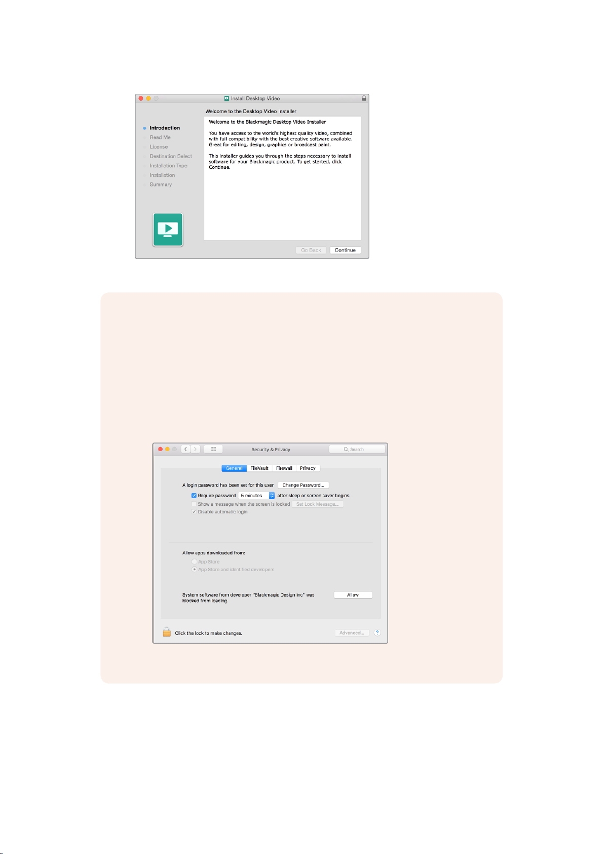
Desktop Video Installer for Mac
NOTE If you are installing Desktop Video on macOS High Sierra for the first time, then
you will need to enable your Mac to use your Desktop Video equipment immediately
after restarting your computer. If at any time a popup window appears asking you to
enable extensions, simply click ‘OK’ and continue.
To enable extensions on macOS High Sierra:
1 Go to ‘system preferences’ and click on ‘security and privacy’.
2 In the ‘security and privacy’ preferences, click ‘allow’ to enable the Desktop
Video software on your computer.
Click ‘allow’ in the security and privacy preferences to enable
the Desk top Video software on your computer
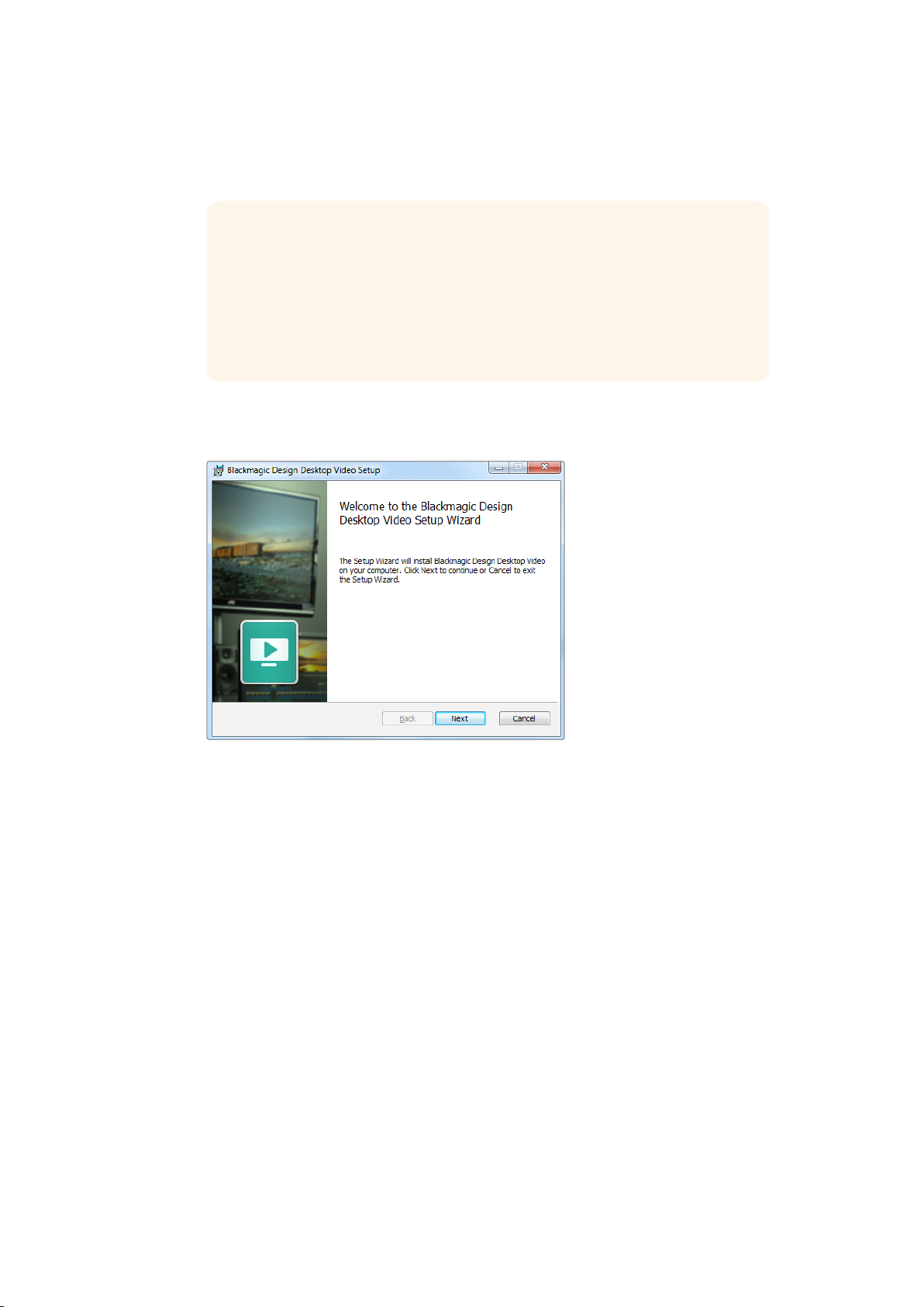
Windows Installation
1 Ensure you have the very latest driver. Visit www.blackmagicdesign.com/support
2 Open the “Desktop Video” folder and launch the “Desktop Video” installer.
3 The drivers will now be installed on your system. An alert will appear: “Do you want to
allow the following program to install software on this computer?” Click ‘yes’ to continue.
1111Getting Started
Page 12
4 You will see a dialog bubble saying “found new hardware” and the hardware wizard
will appear. Select “install automatically” and the system will find the required Desktop
Video drivers.
TIP If you have a DeckLink Quad 2 installed in a Windows 7 computer,
Windows Update will attempt to check each driver in case a newer version is
available. In this particular case it is unnecessary as all drivers in the latest
Desktop Video release are the most recent. You can temporarily disable the
feature by clicking on the notification and then clicking “Skip obtaining driver
software from Windows Update”. Confirm the action by clicking ‘yes’. The
installation will now be a lot faster.
5 After all drivers have been installed, a dialog bubble will appear saying “your new
hardware is ready for use.” Restart your computer to enable the new software drivers.
Desktop Video Installer for Windows
Linux Installation
1 Download the latest Desktop Video software for Linux from
www.blackmagicdesign.com/support
2 Open the Desktop Video folder and navigate to the packages required for your
distribution and architecture. Note that ‘amd64’ refers to Intel and AMD 64 bit
processors. There are three sets of packages provided:
The desktopvideo package provides the core drivers and API libraries.
The desktopvideo-gui package provides the Desktop Video Utility software.
The mediaexpress package provides a simple capture and playback utility.
3 Double click the packages you wish to install and follow the onscreen instructions.
Ifyou see any messages about missing dependencies, ensure they are installed first
and then rerun the Desktop Video installer.
4 When the installer has finished it is recommended that you restart your computer to
complete the installation process.
1212Getting Started
Page 13
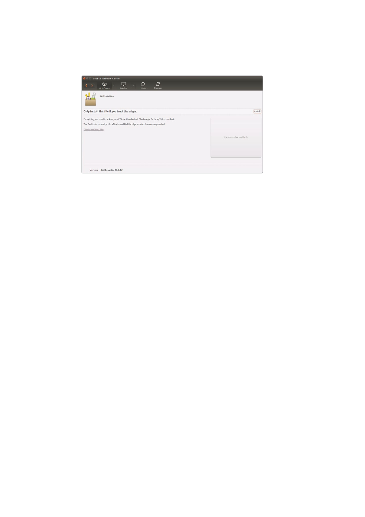
If you cannot find a native Desktop Video package for your Linux distribution, or if you prefer to
install from a command line, refer to the ReadMe file for detailed installation instructions.
Desktop Video software ready to be installed
from the Ubuntu Software Center.
Updates
If you have not installed the utility software, you can check the internal software is up to date
using the BlackmagicFirmwareUpdater command line tool:
# BlackmagicFirmwareUpdater status
A message similar to the following will appear:
0: /dev/blackmagic/io0 [DeckLink SDI 4K] 0x73 OK
1: /dev/blackmagic/io1 [DeckLink 4K Extreme 12G] 0x0A PLEASE _ UPDATE
In this case you could update the internal software with the following command:
# BlackmagicFirmwareUpdater update 1
See the ‘man’ page for a more detailed description of the command’s usage. e.g., for more info
on the internal software updater command, type “man BlackmagicFirmwareUpdater”.
That’s all there is to getting started! Now that you have installed your Blackmagic Desktop
Video hardware and software, you can start capturing and playing back video.
Capturing and Playing Back Video
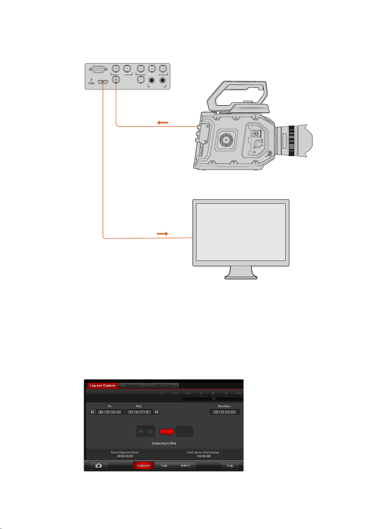
Once the Desktop Video hardware and software is installed, you can start capturing and
playing back clips straight away. First, plug your video source into the input on your Desktop
Video hardware, then connect a monitor to the output.
A quick way to begin capture and playback is to record a clip in Blackmagic Media Express,
which was installed on your computer when you installed the Desktop Video software.
Setting Up
1 Connect a monitor or TV to the video output of your Blackmagic Design hardware.
2 Connect a video source to the input of your Blackmagic Design hardware.
1313Capturing and Playing Back Video
Page 14
REMOTE
HDMI OUT
A B NTSC
SDI IN
SDI OUT
PAL
Y
Ultra Studio HD Mini
REF IN
B-Y R-Y
ANALOG VIDEO IN
CH 1 CH 2
ANALOG AUDIO IN
SDI OUT
SDI IN
REF IN
TC IN
+ 12V
URSA Mini Pro
HDTV
Connect a video monitor and source to your Blackmagic Design video hardware.
Testing Video Capture
1 Launch Blackmagic Media Express. Click on the ‘log and capture’ tab. Your input video
format is automatically detected and Media Express sets the project video format to
match. Your video source will appear in the Media Express preview pane.
2 Click ‘capture’ at the bottom of the ‘log and capture’ window to perform the capture
test. Click ‘capture’ again to finish the test. The captured clip is added to the media list
on the left side of Media Express.
Click the ‘capture’ button to commence recording.
1414Capturing and Playing Back Video
Page 15

Testing Video Playback
1 Click on the ‘playback’ tab.
2 Double click the test clip. The video and any present audio will be sent to the monitor
connected to your hardware’s output.
Blackmagic Desktop Video Utility
Introducing Blackmagic Desktop Video Utility
Blackmagic Desktop Video Utility provides a central location for configuring hardware settings,
plus a real time status display showing the video connected to your hardware’s inputs and outputs.
To launch Blackmagic Desktop Video Utility:
On Mac OS, click Blackmagic Desktop Video in ‘system preferences’ or you can launch
the utility from your ‘applications’ folder.
On Windows 7, click the ‘start’ button>all programs>Blackmagic Design>Desktop Video
and click the Desktop Video utility application. The Desktop Video utility also launches
from the Windows 7 ‘control panel’.
On Windows 8, from the ‘start’ page type ‘Blackmagic’ and then click the Blackmagic
Desktop Video Utility application. The Desktop Video utility also launches from the
Windows 8 ‘control panel’.
On Windows 10, click the ‘start’ button>all programs>Blackmagic Design>Desktop
Video and click the Desktop Video Utility application. The Desktop Video utility also
launches from the Windows 10 ‘control panel’.
On Linux, go to ‘applications’ and then ‘sound and video’ and double click the
Blackmagic Desktop Video Utility application.
When you first open Blackmagic Desktop Video Utility, the home page displays your connected
hardware and provides an overview of all video activity on your hardware’s input and output
connections. If you are sending a video signal to your input, it will be automatically detected
and the format will be displayed under the Video Input icon.
If you have multiple Blackmagic capture and playback devices connected, you can cycle
through them by clicking the arrow buttons on the sides of the home page. To configure
settings, simply click on the hardware image, or the settings icon located below the hardware
name. The Desktop Video utility only displays the settings that are relevant to your selected
hardware, so you don’t have to scroll through pages of menus to find the settings you want.
1515Blackmagic Desktop Video Utility
Page 16
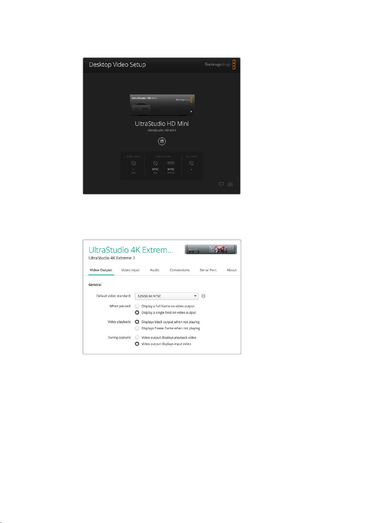
Blackmagic Desktop Video Utility home page
The following pages of this manual will show you how to adjust settings using Blackmagic
Desktop Video Utility.
Blackmagic Desktop Video Utility lets you adjust video and audio
input and output settings, apply up or down conversions during
capture and playback, and provides information about the driver.
Video Settings
Video Input
Click on a connector icon to set the ‘video input’ connection for your Blackmagic Design
hardware. Only the connectors that are built into your hardware will be shown. When a valid
video signal is detected, the input and video format will be displayed on the Blackmagic
Desktop Video Utility home page.
1616Blackmagic Desktop Video Utility
Page 17
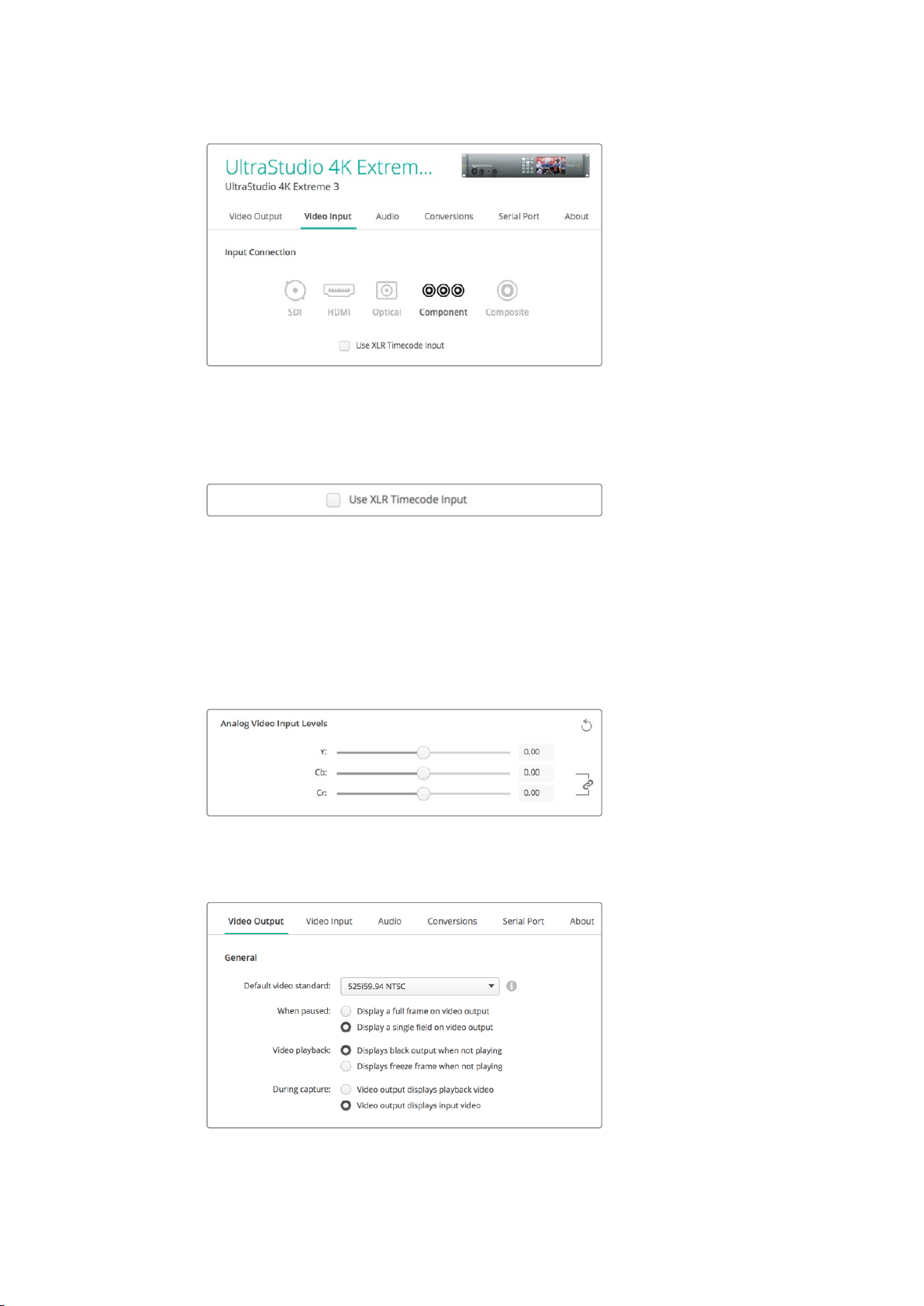
Click on an icon to set your video input connection.
Use XLR Timecode
Select this setting to read timecode from the XLR input instead of the SDI stream.
Enable the checkbox to capture timecode from the dedicated XLR input
Analog Video Input Levels
Drag the ‘video’ and ‘chroma’ sliders to adjust the analog video input levels for component or
composite video. Dragging the video slider affects the luma gain and the chroma sliders
decrease or increase the color saturation. When using component video, you can adjust the
Cband Cr values independently. Click the ‘link’ icon to connect them if you want to adjust them
simultaneously.
Video Output
Select the video standard and adjust other settings for your video output.
Select what to display on the output when paused,
during video playback and during capture
1717Blackmagic Desktop Video Utility
Page 18
General
Default Video Standard
To use broadcast monitoring with Final Cut Pro X, set the output format to match your
Final Cut Pro X project.
When Paused
Click to select whether to display a full frame or a single field on the output
when paused.
Video Playback
Click to select whether to display a freeze frame or black output when not playing.
During Capture
Click to select whether the video output displays the playback video or input video
during capture. If you select the ‘video output displays playback video’ option, then
your selection in the ‘video playback’ section will dictate what is displayed on your
output. If you select the ‘video output displays input video’ option, then the input video
will be displayed on your outputs.
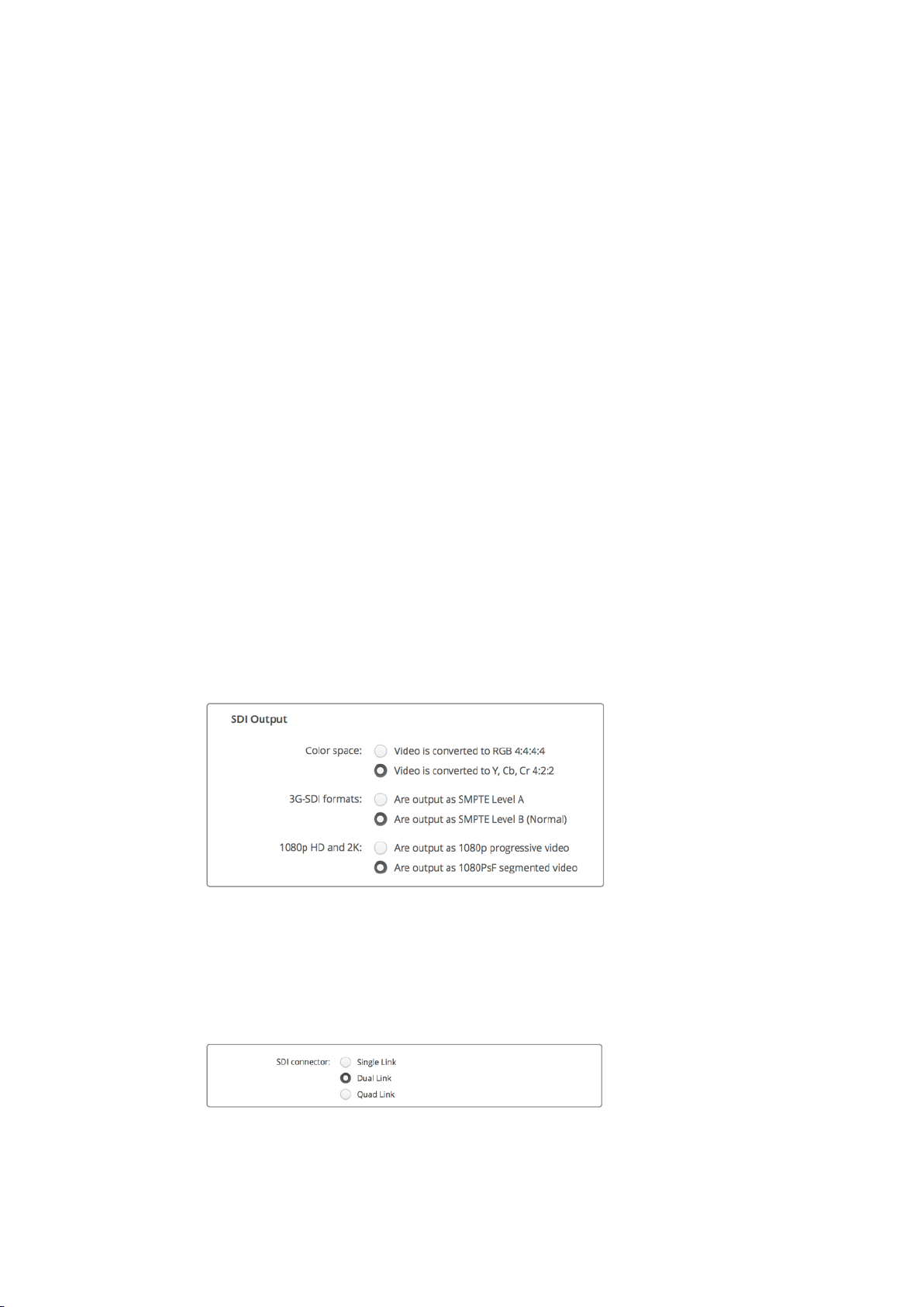
SDI Output
Color Space
Click to select the color space to convert to. Options are 4:4:4 RGB video or Y,
Cb, Cr 4:2:2.
3G-SDI Formats
Click to select whether to output 3Gb/s SDI signals as SMPTE Level A direct mapping
or to have 3Gb/s signals sent with Level B mapping.
1080p HD and 2K
Click to select whether 1080p HD and 2K are output as 1080p progressive video, or as
progressive segmented frame video.
Use the SDI Settings to control the output of your SDI video.
SDI Configuration
Select between single link, dual link and quad link for 3G, 6G or 12G-SDI output. Some
professional color grading monitors and projectors only accept high bandwidth signals
like 2160p60 or DCI 4K 4:4:4 via quad link. UltraStudio 4K Extreme can output quad link
3G-SDI and you can also get a Quad SDI add on card for DeckLink 4K Extreme 12G.
Choose whether to output via single link, dual link
or quad link for 3G, 6G and 12G-SDI video signals
1818Blackmagic Desktop Video Utility
Page 19
Set Analog Video Output
If your Blackmagic Design hardware has shared analog video connectors, you can choose
whether to output your video via ‘component’, ‘composite’ or ‘s-video’ by selecting between the
‘analog video output’ options.
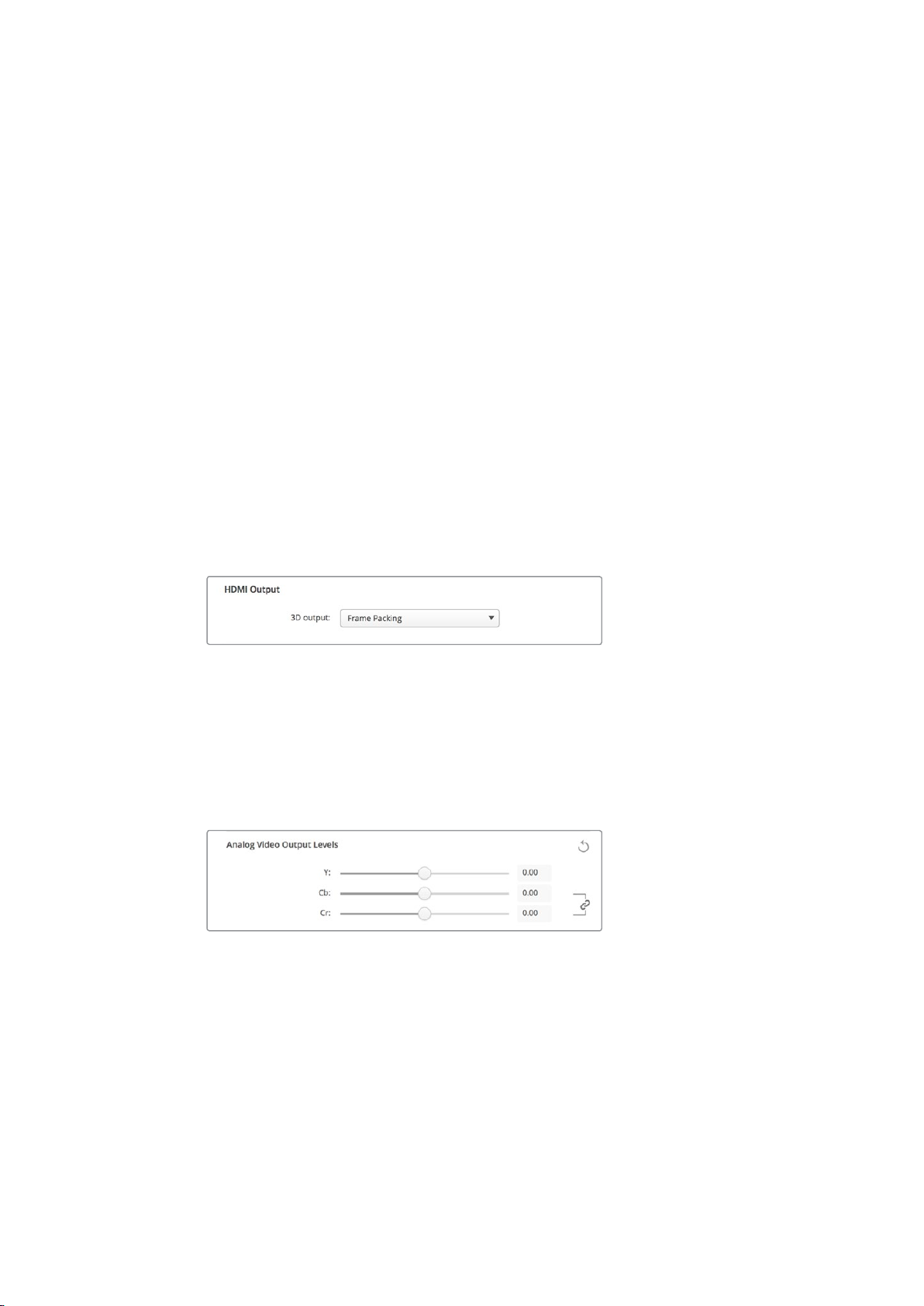
HDMI 3D Output
This setting determines the 3D format for your HDMI monitoring.
Top and Bottom
Arranges both left and right eye images vertically with 50% compression.
Frame Packing
Combines left and right eye images into a single frame without compression.
Side by Side
Arranges both left and the right eye images horizontally with 50% compression.
Left Eye
Only the left eye image is displayed.
Line by Line
The left and right eye images are carried on alternate video lines without compression.
Right Eye
Only the right eye image is displayed.
Set your HDMI 3D Output format.
Analog Video Output Levels
Drag the ‘video’ and ‘chroma’ sliders to adjust the analog video output levels for component or
composite video. Dragging the video slider affects the luma gain and the chroma sliders
decrease or increase the color saturation. When using component video, you can adjust the
Cband Cr values independently. Click the ‘link’ icon to connect them if you want to adjust
themsimultaneously.
Adjust the video slider to set composite analog video
output levels, and the Cb and Cr sliders for controlling
color balance when using component video.
Use Betacam Levels
Blackmagic Design products use SMPTE component analog levels to maintain
compatibilitywith most modern video equipment. Enable the checkbox if working with
Sony Betacam SP decks.
NTSC IRE
Select the 7.5 IRE setup for the NTSC composite video used in the USA and other
countries. Select the 0 IRE setup if you’re working in Japan or countries that don’t use
the 7.5 IRE setup. PAL and high definition formats do not use this setting.
1919Blackmagic Desktop Video Utility
Page 20
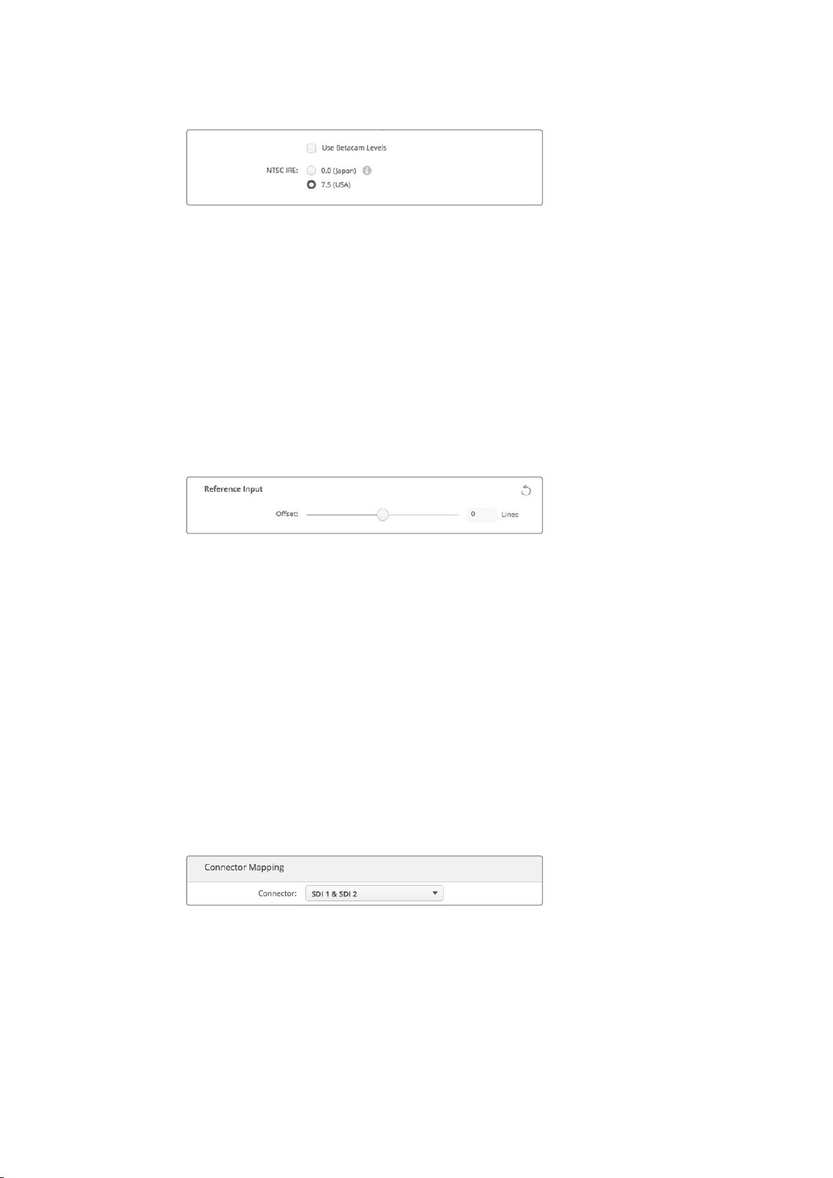
Enable the ‘use Betacam levels’ checkbox when working
with Sony Betacam SP decks. Select the relevant NTSC
IRE level when using an NTSC composite video format.
Reference Input
The reference adjustment lets you adjust the timing of the video outputs of your hardware
relative to the video reference input. This is commonly used in large broadcast facilities where
the video output needs to be accurately timed. The reference adjustment is in samples so you
can get an extremely accurate timing adjustment down to the sample level.
A common example of how this setting would be used is where all the hardware in your
facilityhas a stable common reference connected and then all the devices would have the
timing set so the video outputs all match perfectly. This would then make it possible to switch
between devices on a downstream router or production switcher and would eliminate any
glitching whenswitching is performed.
If locking to a reference, adjust this setting to time
the video output relative to the reference input.
Connector Mapping for DeckLink Quad 2
If you have a DeckLink Quad 2 installed in your computer, you can input or output SDI signals
over 8 independent mini BNC connectors. This gives you the ability to capture or play back 8
separate video streams, similar to having 8 capture and playback devices in a single product.
This is why your DeckLink Quad 2 appears in Desktop Video Utility as 8 individual DeckLink
Quad devices which makes it easier to configure your inputs and outputs. You can even name
each device so you can keep track of which DeckLink Quad device is being used for a specific
video signal.
SDI connectors can be mapped to each device using the ‘connector mapping’ settings in the
Desktop Video utility, but it’s important to know that specific connectors are dedicated to
specific devices. For example, SDI 1 is dedicated to DeckLink Quad (1), and SDI 2 is dedicated
to DeckLink Quad (1) and DeckLink Quad (5).
If you have a DeckLink Quad 2 installed, the ‘connector mapping’ setting
lets you assign SDI connectors to each DeckLink Quad device.
You can see which SDI connectors are dedicated to each DeckLink Quad device by looking at
the table below, where you can also check the mapping options for them.
2020Blackmagic Desktop Video Utility
Page 21

Mapping Options
DeckLink Quad Devices Dedicated SDI Connectors
DeckLink Quad (1) SDI 1 and 2 or SDI 1
DeckLink Quad (2) SDI 3 and 4 or SDI 3
DeckLink Quad (3) SDI 5 and 6 or SDI 5
DeckLink Quad (4) SDI 7 and 8 or SDI 7
DeckLink Quad (5) SDI 2 or none
DeckLink Quad (6) SDI 4 or none
DeckLink Quad (7) SDI 6 or none
DeckLink Quad (8) SDI 8 or none
It’s worth mentioning that when configuring an SDI connector for a specific device, it will also
affect the device sharing that connector. For example, if DeckLink Quad (1) is set to use SDI 1
and 2, DeckLink Quad 5 will automatically be set to ‘none’ because its shared SDI connector is
being used. Alternatively, if you select SDI 2 on DeckLink Quad (5), DeckLink Quad (1) will
automatically be set to SDI 1. For this reason, it’s important to note which SDI inputs or outputs
are being used by each device to avoid accidentally interrupting the input or output of
another device.
TIP If you have an original DeckLink Quad installed in your facility and are using a
custom designed SDK application, you can be confident that installing DeckLink Quad
2 will work in your system without having to make any changes to your application.
Additional mapping features in your DeckLink Quad 2 will allow you to build on your
existing system to provide even more input and output configurations if you need them.
Audio Settings
Audio Input
Click on a connector icon to set your ‘audio input’ connection for your Blackmagic Design
hardware. You can select from the following inputs:
Embedded
Includes audio channels as part of video signals. SDI and HDMI are capable of carrying
embedded audio.
AES/EBU
Is a digital audio signal that can carry 2 audio channels over a single connector.
XLR
Is a three pin audio connector that is predominantly used by professional analog audio
equipment.
RCA or HIFI
Is a connector used to connect unbalanced analog audio to and from consumer audio
equipment, such as HiFi systems, DVD players and televisions.
2121Blackmagic Desktop Video Utility
Page 22
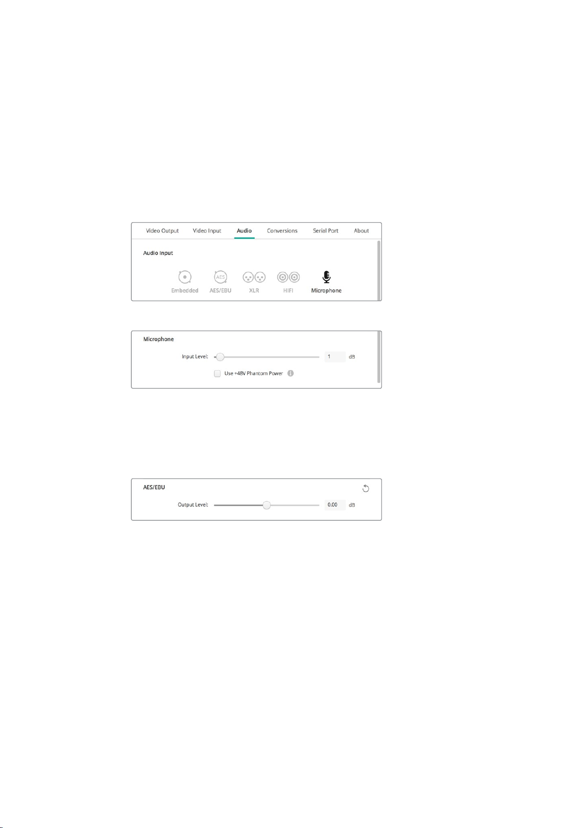
Microphone
Phantom power supplies power through microphone cables and is a convenient power
source for condenser microphones.
Enable the ‘use +48V phantom power’ option if your microphone requires phantom
power. If you’re unsure whether your mic needs phantom power or not, it’s best to leave
this box unchecked as there is a risk of causing damage to microphones that are self
powered. An LED on the front of UltraStudio 4K Extreme will illuminate when phantom
power is active. Be sure to wait at least 10 seconds for phantom power to discharge
after disconnecting before plugging in a self powered microphone. Olderribbon type
microphones and dynamic microphones are not suitable for phantom power usage.
Click on a connector icon to set your ‘audio input’ connection.
Drag the ‘input level’ slider to control your microphone input level.
AES/EBU
Drag the sliders to adjust the ‘ref’ level, or gain, for the AES/EBU audio inputs and outputs.
Press the reset icon to reset the gain to 0 dB.
Drag the ‘output level’ slider to control your AES/EBU digital output level.
Analog Audio Input Levels
Channel 1/Channel 2
These settings adjust the gain for the analog audio inputs when capturing. Click the
‘link’ icon to adjust them simultaneously.
Use HiFi Audio Levels
Professional XLR connectors are standard on UltraStudio and DeckLink models. If you
want to connect consumer audio equipment to the XLR connectors, make sure you
enable the ‘use HiFi audio levels’ checkbox as the audio levels between professional
and consumer equipment differ. You’ll also need to use an RCA to XLR adapter.
2222Blackmagic Desktop Video Utility
Page 23
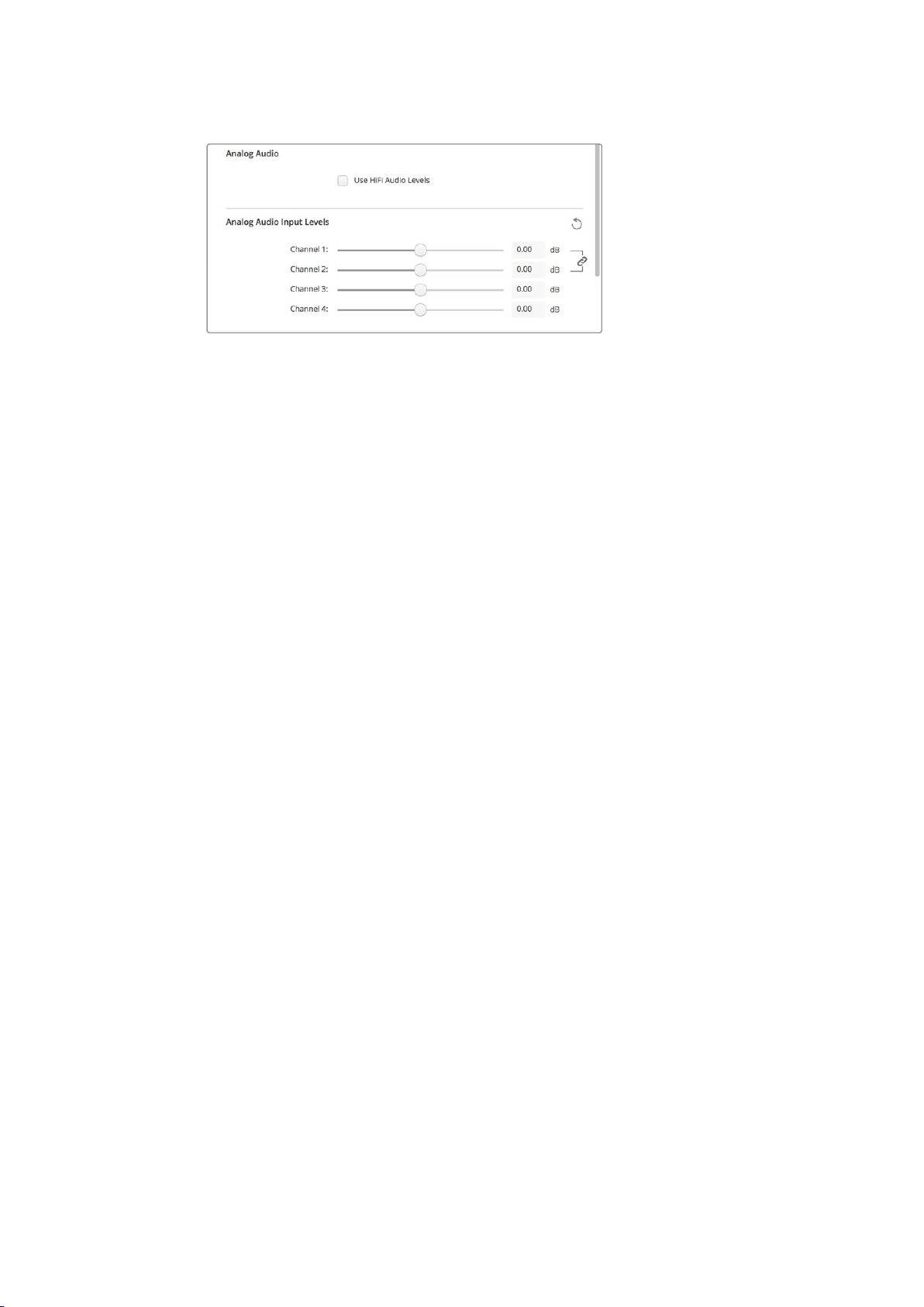
Adjust the input channel sliders to control your analog
audio input levels. Enable the ‘use HiFi audio levels’
checkbox if connecting consumer audio equipment.
Analog Audio Output Levels
Channel 1/Channel 2
These settings adjust the strength of the audio signal, or gain, for the analog audio
outputs while playing back video. Click the ‘link’ icon to adjust them simultaneously.
Reset Icon
When adjusting sliders, you may want to cancel your change. The reset icon is the circular arrow
located at the right of each settings’ title bar. Press the reset icon in each setting to restore the
gain sliders to 0 dB.
Conversions Settings
Input Conversion
This setting enables real time up and down conversion during capture. Select your desired
conversion from the ‘input conversion’ dropdown menu.
Input conversion results in up to a 2 frame delay, so you’ll need to adjust your editing software’s
timecode offset to ensure frame accuracy.
Display As
Select how you would like your converted video presented. Depending on your input
video’s original aspect ratio, options may include letterbox, anamorphic, center cut,
pillarbox, 16:9 zoom or 14:9 zoom.
Output Conversion
This setting enables real time up and down conversion during playback. Select your desired
conversion from the dropdown menu.
Output conversion results in up to a 2 frame delay, so you’ll need to adjust your editing
software’s timecode offset to ensure frame accuracy.
Convert Analog Outputs
Enable this checkbox to also perform your conversion on the analog video outputs.
Display As
Select how you’d like your converted video presented. Depending on your video’s
original aspect ratio, options may include letterbox, anamorphic, center cut, pillarbox,
16:9 zoom or 14:9 zoom.
2323Blackmagic Desktop Video Utility
Page 24
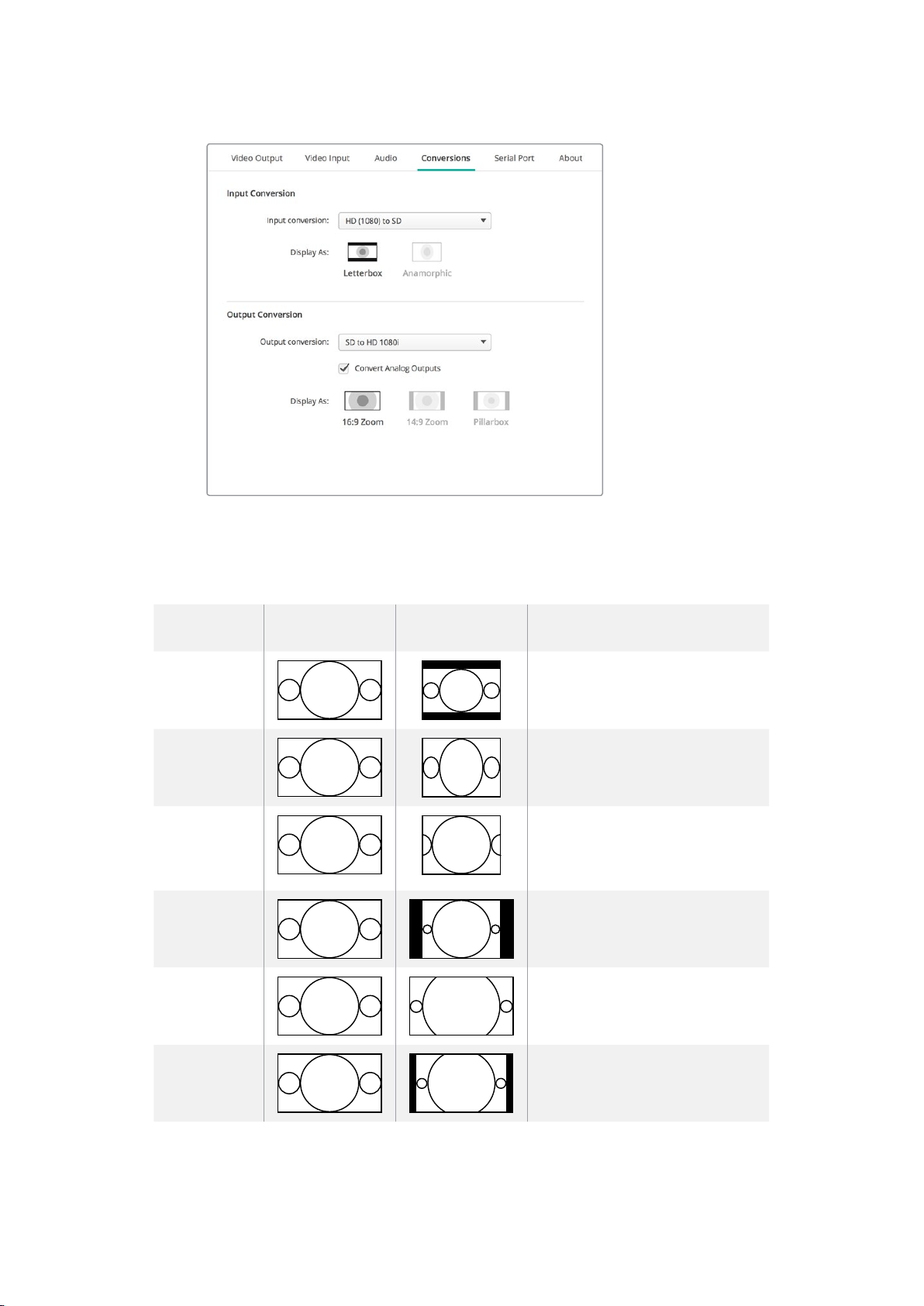
To set your up or down conversion settings, select your input or output
conversion from the respective dropdown menu, and click on the desired
aspect ratio selection. Remember to click ‘save’ to apply your settings.
The following table outlines the different aspect ratio selections available during conversions.
Down
Conversion
Letterbox
Anamorphic
Center Cut
Pillarbox
16:9 Zoom
14:9 Zoom
Source
Image
Converted
Image
Scales the entire 16:9 HD image into
a 4:3 SD frame leaving black bars on
the top and bottom.
Horizontally squeezes the 16:9
HDimage into a 4:3 SD frame.
This setting cuts a 4:3 SD frame from
the 16:9 HD image. This aspect ratio
setting discards a portion from each
side of the 16:9 image.
Displays a 4:3 SD image inside an
16:9 HD frame. Black bars feature
onthe sides.
Scales the 4:3 SD image to fill
the16:9 HD frame.
A compromise between Pillarbox
and 16:9 Zoom. Minimal black bars
with slight crop top and bottom.
2424Blackmagic Desktop Video Utility
Page 25
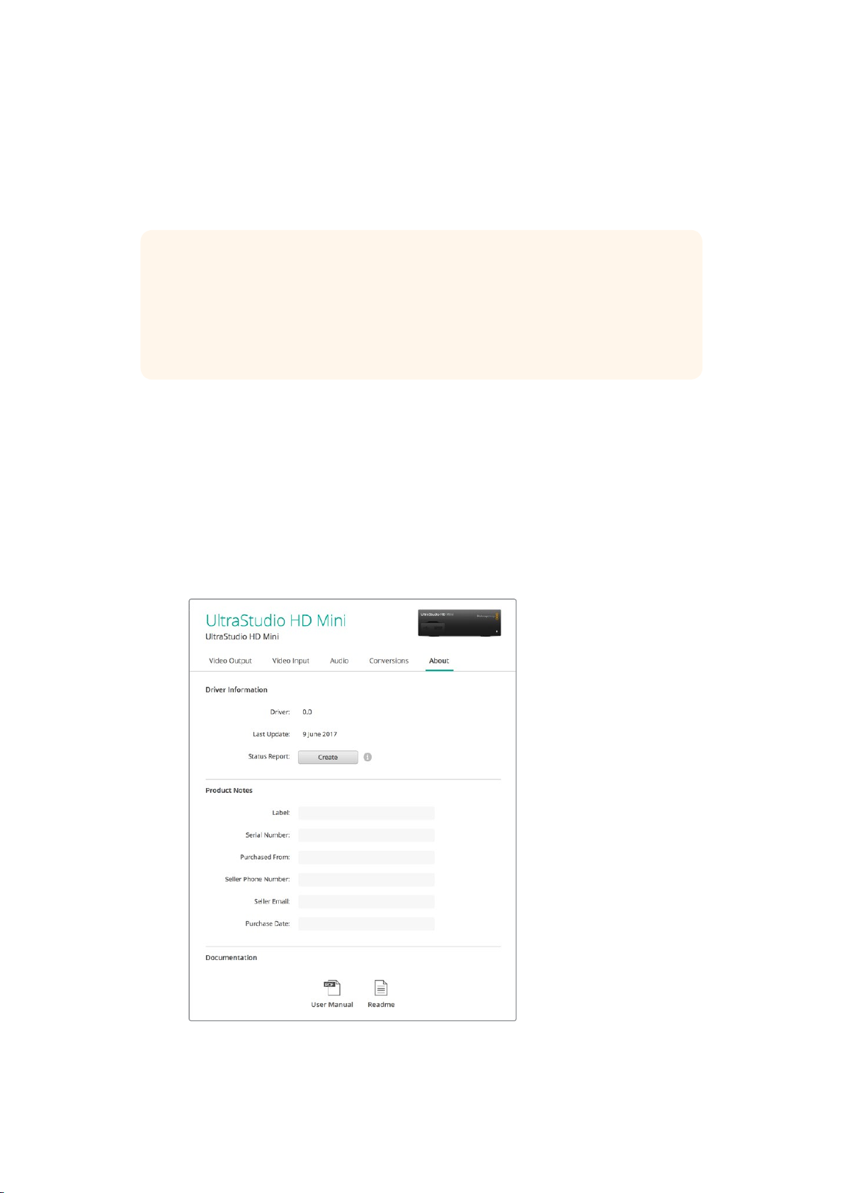
About
Driver
The ‘about’ page in Blackmagic Desktop Video Utility provides information about your
hardware’s current driver and the last time your hardware was updated.
TIP You can generate a status report by clicking on the status report ‘create’ button,
which lets you save a file containing technical information such as the video format
detected on your input and output, color space, color sampling and bit depth, driver
information, operating system and machine information. This report can be useful if you
ever need to contact our technical support team. The file is also very small so can be
easily emailed.
Product Notes
Changing the name of your Blackmagic Design equipment lets you identify each unit in the
Desktop Video utility software and keep track of where and how it’s being used. This is useful
ifyou have the same hardware in various locations on a network, plus it can be handy to name
the different units for their purposes, e.g., Edit Suite 2, Color Suite 1, etc.
When you enter a name for your hardware in the label field, it is saved to the
BlackmagicDesktop Video Utility home page and displayed beneath the hardware image.
You can also enter important information that you may want to refer to later, such as the hardware
serial number, where and when your hardware was purchased, as well as the seller’s contact details.
The ‘about’ section provides valuable information such as the driver
version, user manual and release notes. You can also generate a
status report and enter product notes specific to your hardware.
2525Blackmagic Desktop Video Utility
Page 26
Teranex Mini Smart Panel
1
2
SET
VIDEO
MENU
AUDIO
Attaching a Teranex Mini Smart Panel
Blackmagic UltraStudio HD Mini is a small capture and playback solution that shares a similar
form factor to other Blackmagic equipment like Teranex Mini converters and recording decks
such as HyperDeck Studio Mini. These products are designed to be portable and modular so
you can take them with you on location, mount them on your desk, or attach them to a Teranex
Mini Rack Shelf. The rack shelf lets you mount the equipment in a rack.
Attaching an optional Teranex Mini Smart Panel to your UltraStudio HD Mini allows you to
preview video and audio directly from the front of the unit during playback and capture.
The built in LCD on the Teranex Mini Smart Panel displays the input image as well as audio
meters, which allow you to preview your audio levels.
The Panels are hot swappable so you don’t even need to turn off your Blackmagic UltraStudio
HD Mini when installing it.
1 Remove the two M3 screws on each side of your Blackmagic UltraStudio HD Mini’s
basic front panel using a Pozidriv 2 screwdriver and gently pull the panel away from the
front of your the unit.
2 On the inside of the basic panel, you’ll notice a small clear plastic tube attached to
the bottom corner. This tube directs light from the LED inside the unit to illuminate
the status indicator on the basic panel. This tube should stay attached to the basic
front panel.
TIP If reattaching the basic front panel, make sure the light tube is aligned with
the slot in the front of the unit.
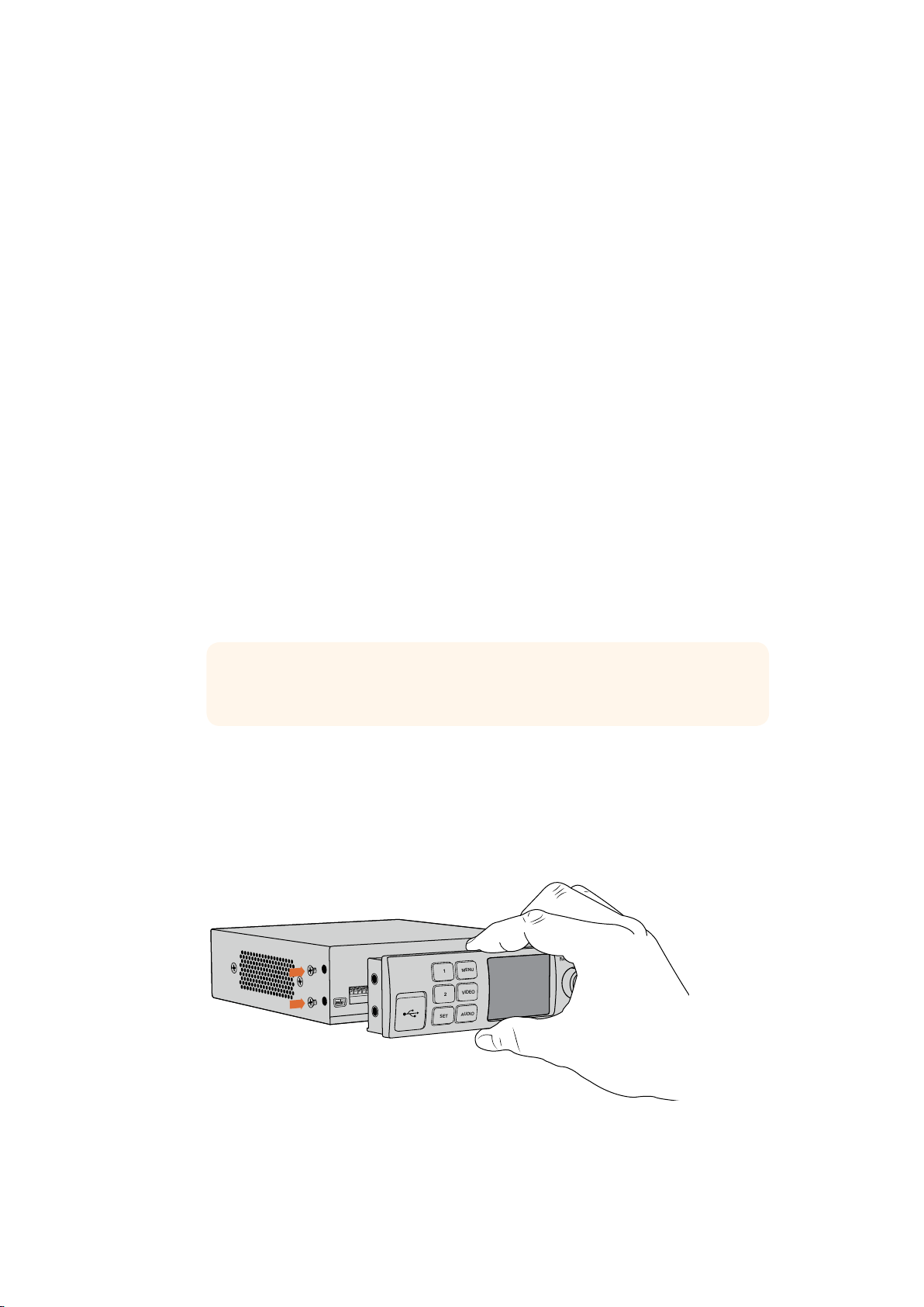
3 Align the connector on the rear of the Teranex Mini Smart Panel with the corresponding
connector on the face of your UltraStudio HD Mini and gently push the Smart
Panel towards the unit until the connectors are firmly seated. The Teranex Mini
Smart Panel should make a firm connection and fit neatly inside the face of your
UltraStudio HD Mini.
4 Re-insert the M3 screws from the original panel.
When installing the Teranex Mini Smart Panel to your Blackmagic
UltraStudio HD Mini, holding the panel with your fingers and thumb
aligned with the panel’s rear connector will help guide it into place
If your UltraStudio HD Mini is installed in a Teranex Mini Rack Shelf, you will need to remove the
unit from the rack shelf to access the front panel screws.
2626Teranex Mini Smart Panel
Page 27
See the ‘Teranex Mini Rack Shelf’ section for more information.
Video Format
525i59.94 NTSC
Buffer
55 fr
The original basic panel is very strong, so if you need to mount your Blackmagic UltraStudio HD
Mini in the back of a rack system or in areas where there are lots of cables or activity, you can
always reinstall the original basic panel.
Smart Panel Features
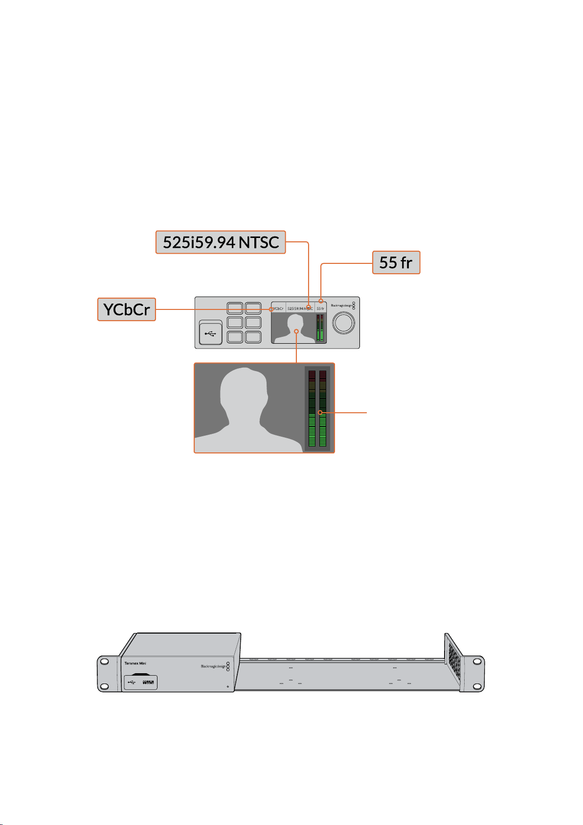
LCD Display
The home screen is the first feature you’ll see on your Teranex Mini Smart Panel’s LCD display.
The home screen shows you important information, including:
Video format – The video format
being captured or played back.
Buffer – The number of frames that
can be buffered on the device during
capture or the number of frames
buffered on the device during playback.
Source – The video
input source type. SDI,
YCbCr or NTSC/PAL.
1 MENU
2 VIDEO
SET AUDIO
Source
YCbCr
Video Format
525i59.94 NTSC
Buffer
55 fr
Audio meters – Displays
the audio levels of the
video source connected
to UltraStudio HD Mini.
Video monitor – Displays the
input video source that is connected
to UltraStudio HD Mini.
Teranex Mini Rack Shelf
When using Blackmagic UltraStudio HD Mini with other equipment like Blackmagic
ATEMTelevision Studio HD or Blackmagic Teranex Mini converters, you can use Teranex Mini
Rack Shelf to install your units into a broadcast rack or road case. Up to three Teranex Mini
sized units can fit neatly onto each 1RU Teranex Mini Rack Shelf.
UltraStudio HD Mini is installed into the rack shelf by removing the unit’s rubber feet, if attached,
and screwing the unit into the base of the shelf using the mounting holes on the underside.
UltraStudio HD Mini
The Teranex Mini Rack Shelf ships with two original blank panels which you can use to cover
gaps if you don’t need to install additional units.
For more information, check the Blackmagic Design website at www.blackmagicdesign.com
2727Teranex Mini Rack Shelf
Page 28
DaVinci Resolve
Live Grading with DaVinci Resolve
Desktop Video 10 allows simultaneous capture and playback on Blackmagic Design 4K
hardware. This is great for users who want to use the live grading feature within DaVinci
Resolve, as it means you don’t require two separate devices for input and output.
When using live grading on set, simply connect the output of the camera to the input of your
Blackmagic Design hardware. Then connect the hardware’s output to an on set monitor for
grading evaluation and viewing.
Setting Up
1 Launch DaVinci Resolve. From the preferences menu, select the ‘video and Audio
I/O’ tab and select your hardware from the ‘for Resolve Live use’ option. Save your
preferences and restart DaVinci Resolve to apply your changes.
2 Start a project and from within the ‘project settings’ window, set the resolution and
frame rate to match your camera.
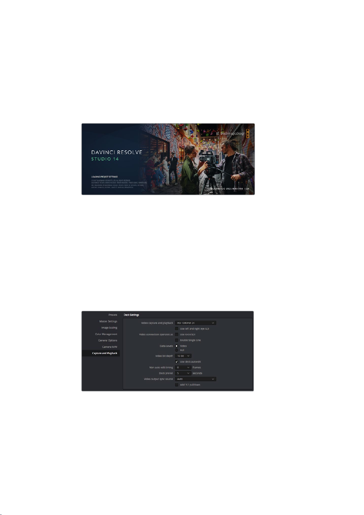
3 In the ‘project settings’ window, go to the ‘capture and playback’ tab and select your
desired format from the ‘video capture and playback’ menu.
Select your format from the ‘video capture and playback’ menu.
4 Go to the ‘edit’ page and select file>new timeline.
5 From the ‘color’ page, select color>Resolve Live. You should now see live video within
the viewer and a bright red ‘Resolve Live’ button will appear above the video.
2828DaVinci Resolve
Page 29
Using Resolve Live
1 In Resolve Live mode, the ‘freeze’ button (snowflake icon) freezes the current incoming
video frame, so you can grade it without being distracted by motion occurring
during the shoot. When you’ve made the adjustment, you can unfreeze playback in
preparation for grabbing a snapshot.
2 Once you’re happy with a grade, clicking the ‘snapshot’ button (camera icon) saves a
snapshot of the current still in the viewer, the incoming timecode value, and your grade
into the timeline. Snapshots are simply one frame clips.
TIP Please refer to the DaVinci Resolve manual for more information on Resolve Live.
Editing with DaVinci Resolve
Blackmagic DaVinci Resolve features an editor friendly interface with all the tools to edit and
finish projects. Whether you use the mouse to drag and drop clips, or your keyboard for
precision editing, DaVinci Resolve features all of the functionality professional editors require.
Setting Up
1 Launch DaVinci Resolve. From the ‘preferences’ menu, select the ‘video I/O and GPU’
tab and select your Blackmagic Design hardware from the ‘for capture and playback
use’ option. Save your preferences and restart DaVinci Resolve to apply your changes.
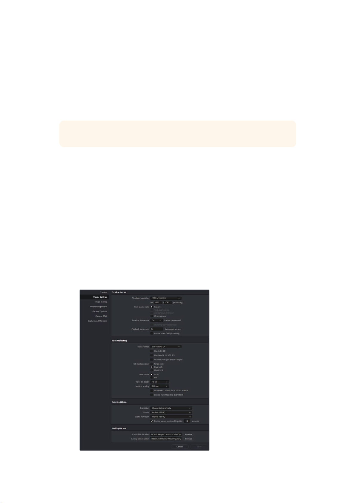
2 Load a project, and from within the ‘project settings’ window, set your ‘timeline
resolution’, ‘timeline frame rate’ and ‘playback frame rate’.
3 Under the ‘video monitoring’ section, set your ‘video format’. This is the format that will
be used for the output from your Blackmagic Design hardware.
4 Click the ‘save’ button to save the changes and close the project settings window.
Use the ‘project settings’ window to set your timeline
format and video monitoring options.
2929DaVinci Resolve
Page 30
Editing
1 Use the browser on the ‘media’ page to load your clips into the media pool.
2 On the ‘edit’ page, select file>new timeline, name your timeline and click the
“createnew timeline” button.
3 On the ‘edit’ page, drag a clip from the media pool to the source viewer.
4 You can set the in and out points in source clips by using the I and O keys.
5 To edit the clip into the timeline, simply drag and drop the clip from the source viewer
into the timeline.
TIP Refer to the Blackmagic DaVinci Resolve manual for more detailed information on
how to edit with DaVinci Resolve.
Using your Favorite 3rdPartySoftware
Adobe After Effects CC
After Effects CC 2017
How to Preview Video
To display your composition in real time through your Blackmagic Design hardware, go to
preferences > video preview. ‘Mercury transmit’ must be enabled in order to use your
Blackmagic Design hardware with After Effects CC. Under ‘video devices’, select Blackmagic
Playback. You can now use a broadcast monitor to view your After Effects compositions in the
correct video colorspace.
3030Using your Favorite 3rd Party Software
Page 31

‘Video Preview’ preferences
If you work with unsupported or non standard frame sizes, these can also be correctly outputted
by your Blackmagic Design hardware. Go to preferences > video preview and click the ‘setup’
button next to ‘Blackmagic playback’. The ‘Blackmagic device selection’ window will appear. You
can scale your image up or down to the next closest video standard supported by your
hardware. For example, if you are using UltraStudio 4K and your After Effects composition is set
to a resolution of 2048 x 1152, scaling down will output DCI 2K, scaling up will output Ultra HD.
Rendering
When you have completed your composition, you can render a DPX image sequence or any of
the following codecs:
‘Output Module Settings’ rendering options
3131Using your Favorite 3rd Party Software
Page 32

QuickTime codecs on Mac OS
Blackmagic RGB 10 bit (uncompressed)
Apple Uncompressed YUV 10 bit 4:2:2
Apple Uncompressed YUV 8 bit 4:2:2
Apple Photo - JPEG (compressed)
Apple DV - NTSC (compressed)
Apple DV - PAL (compressed)
Other codecs including ProRes and DVCPRO HD will be available if you have Final Cut Pro
installed.
AVI codecs on Windows
Blackmagic 10 bit 4:4:4 (uncompressed)
Blackmagic 10 bit 4:2:2 (uncompressed)
Blackmagic HD 8 bit 4:2:2 (uncompressed)
Blackmagic SD 8 bit 4:2:2 (uncompressed)
Blackmagic 8 bit MJPEG (compressed)
Other codecs including DVCPRO HD and DVCPRO50 will be available if you have Premiere Pro
CC installed.
QuickTime codecs on Windows
Blackmagic RGB 10 bit (uncompressed)
Blackmagic 10 bit (uncompressed)
Blackmagic 8 bit (uncompressed)
Apple Photo-JPEG (compressed)
Apple DV - NTSC (compressed)
Apple DV - PAL (compressed)
Adobe Photoshop CC
Photoshop CC 2017
How to Import and Export Video Frames
Import an image into Photoshop CC
1 Select file > import > Blackmagic image import.
2 Select the ‘video input format’ and the ‘image bit depth’ and then click ‘import image’.
3232Using your Favorite 3rd Party Software
Page 33

Image Capture
Export an image from Photoshop CC
1 Select file > export > Blackmagic image export.
2 Select ‘video output format’ and then click ‘export image’.
Image Export
Once you have set the ‘import’ or ‘export’ options, subsequent imports and exports will
notdisplay the settings window. However, you can still change your settings, by holding the
Option[Mac] or Ctrl [Win] key, when selecting import or export.
Adobe Premiere Pro CC
Premiere Pro CC 2017
Setting Up a Blackmagic Design Project
1 Create a ‘new project’ and set the desired ‘location’ and ‘name’ for your project.
2 Click on the ‘scratch disks’ tab to set the locations for your captured video, captured
audio, video previews and audio previews.
3333Using your Favorite 3rd Party Software
Page 34

3 If your graphics card is supported by Premiere Pro CC’s Mercury Playback Engine,
therenderer option will be available and you should switch it to Mercury Playback
Engine GPU acceleration.
4 Set the Capture Format to Blackmagic capture and click ‘settings’ [Mac] or ‘properties’
[Win] to set the video standard and video format. Click OK and your project will open.
5 Make sure your Blackmagic Desktop Video device is NOT set as the default audio
device for your computer’s system audio.
On Mac OS, go to system preferences and select ‘built-in mic’ as the input and ‘internal
speakers’ as the output.
On Windows, go to the task bar and right click on the audio ’speaker’ icon to open
thesound settings. Click on the ‘playback’ tab and set your PC to use the on board
sound hardware or a sound output device other than your Blackmagic Design
hardware. Clickon the ‘recording’ tab and set the computer to use a recording device
other than your Blackmagic Design hardware.
6 Go to Adobe Premiere’s audio hardware preferences and set ‘Adobe desktopaudio’
to ‘built-in output’ using the dropdown menu. Also set ‘output mapping’ to
‘Adobedesktop audio’.
In the ‘playback’ preferences, go to ‘audio device’ and set it to ‘Blackmagic playback’.
Ensure the ‘Blackmagic playback’ checkbox is also selectedunder the
‘videodevice’ settings.
When setting up Adobe Premiere’s audio hardware
preferences, make sure the default audio output and
output mapping settings are set to ‘built-in output’.
3434Using your Favorite 3rd Party Software
Page 35

Set Adobe Premiere’s ‘playback’ audio device to “Blackmagic
Playback’ and be sure to check the ‘Blackmagic Playback’
checkbox in the ‘video device’ settings.
7 To create a new sequence, click file > new > sequence. Select the desired
Blackmagicpreset, give the sequence a name and then click OK.
Create a new sequence from the Blackmagic Design presets
3535Using your Favorite 3rd Party Software
Page 36

Device Control
Many Blackmagic Design capture and playback models feature RS-422 device control for
controlling decks. Click preferences > device control, and check that Blackmagic device control
has been selected from the ‘devices’ menu.
Select an option to output unsupported frame sizes.
Playback
To ensure your video and audio plays back through your Blackmagic Design device, check your
‘playback settings’ by going to preferences > playback. Select ‘Blackmagic playback’ in both
the ‘audio device’ and ‘video device’ menus.
If you work with unsupported or non-standard frame sizes, these can also be correctly
outputted from your Blackmagic Design hardware. Go to preferences > playback, and click the
‘setup’ button next to ‘Blackmagic playback’. The ‘Blackmagic device selection’ window will
appear. You can scale your image up or down to the next closest video standard supported by
your hardware. For example, if you are using UltraStudio 4K and your Premiere sequence is set
to a resolution of 3996 x 2160, scaling down will output Ultra HD, scaling up will output DCI 4K.
Capture
To capture choose:
File > capture [F5]
Set your capture and device control settings in the capture window
To immediately capture, or to capture from a non-controllable device, click the red record
button [G].
3636Using your Favorite 3rd Party Software
Page 37

If you wish to log the clip using RS-422 deck control, enter the desired in and out points using
either the ‘set in’ and ‘set out’ buttons, or manually by typing the timecode and clicking ‘log clip’.
The empty clip will now appear in the ‘project’ window. Repeat this until you have logged all of
the clips you wish to batch capture.
Then choose: File > batch capture [F6]. To set handles on the clips, enable the option to capture with
handles and type the number of additional frames you require at the start and end of each clip.
Export to Tape
If you want to export your edit to an external deck, you can do so using Premiere’s ‘export to
tape’ feature. Choose between two export types: insert and assemble. Insert editing requires
unbroken timecode over the full length of the project which is to be laid to tape. In assemble
mode the tape needs only to be “blacked” until a point just beyond the start time of the project.
As assemble editing erases the tape ahead of the record heads, it should not be used where
other projects already exist on the tape after the out point of your edit.
Use the ‘export to tape’ feature to export your edit to an external deck
To export to tape via RS-422 deck control:
1 Make sure the Adobe Premiere preferences are configured correctly as described in
‘setting up a Blackmagic Design project’ earlier in this section.
2 Open Premiere’s ‘edit to tape’ window by clicking File > export > tape (serial device).
Click on ‘recorder settings’, select Blackmagic capture > settings > format and set the
‘capture format’ to match your desired output format. If the capture format does not
match the output format, it can cause confusion for the deck during preroll and audio
might not be exported.
3 Now set your desired export type by selecting ‘assemble’, or ‘insert’, enter the desired
in point and click OK on a Mac, or ‘export’ on Windows.
When editing to tape, the software waits at the first frame of your project for the deck to drop into
record at the predetermined timecode. Should you find that either the first frame of your program
is repeated or lost during the edit to tape procedure, you will need to adjust the ‘playback > video
device > offset’ setting to bring the deck and computer in sync. You should only need to do this
once with any combination of deck and computer and the correct setting will be retained.
Your sound settings only need to be changed for the ‘export to tape’ feature. Don’t forget to go
back into your computer sound settings and restore them to their earlier state or your workflow
may be affected.
3737Using your Favorite 3rd Party Software
Page 38

Final Cut Pro X
You can use the broadcast monitoring feature of Final Cut Pro X 10.0.4 and later to output your
video through Blackmagic Design video hardware. You can also use two computer monitors for
the Final Cut Pro X interface.
Final Cut Pro X
Setting Up Final Cut Pro X
1 Ensure you are running Final Cut Pro X 10.0.4 or later with the latest version of Mac OS.
2 Open Blackmagic desktop Video Utility. Click on the ‘default video standard’ drop
down menu and then set the same format that you will use in your Final Cut Pro X
project, e.g. HD 1080p29.97. The format should be the same as the video format of
your clips.
Set the ‘output format’ to match your Final Cut Pro X project format.
3 Launch Final Cut Pro X and create a new project.
4 Type a name and choose a location for the new project.
5 Set the ‘video properties’ to ‘custom’ and then set the format, resolution and frame rate
to match the output format set in Blackmagic Desktop Video Utility.
6 Set the ‘audio and render properties’ to ‘custom’. Set the audio channels to stereo
or you can choose ‘surround’ for 6 audio channels. Set the audio sample rate to the
television rate of 48kHz. Set the render format to the same format as your videoclips.
Final Cut Pro X defaults to using ProRes compression but you can switch this to
Uncompressed 10-bit 4:2:2 for an uncompressed workflow. Click OK to complete the
creation of your new project.
3838Using your Favorite 3rd Party Software
Page 39

Set the ‘audio and render properties’ to ‘custom’.
7 Go to the Final Cut Pro menu, choose ‘preferences’ and then click the ‘playback’ tab.
Ensure the ‘A/V output’ menu has selected ‘Blackmagic’ and the same video standard
as your project and then close the preferences.
8 Go to the ‘window’ menu and select ‘A/V output’ to enable video output via your
Blackmagic Design video hardware.
If you wish to monitor audio via your Blackmagic Design video hardware, open the ‘system
preferences’,
click the ‘sound’ icon, click the ‘output’ tab and then select ‘Blackmagic Audio’ for the
sound output.
Playback
1 Import some clips in to your new project.
2 You can now use the Final Cut Pro X timeline on your computer monitor and view the
video preview on the monitor or TV connected to the output of your Blackmagic Design
video hardware.
Capturing Video and Audio
You can use Blackmagic Media Express to capture video and audio with your Blackmagic
Design video hardware. Once you have captured the clips, you can import them in to Final Cut
Pro X for editing.
When capturing clips with Media Express, make sure you choose one of the video formats that
is also supported by Final Cut Pro X, i.e.: Apple ProRes 4444, Apple ProRes 422 (HQ), Apple
ProRes 422 or Uncompressed 10-bit 4:2:2.
Editing to Tape
Once you have completed a project in Final Cut Pro X, you can render the project to a movie
file and then use Blackmagic Media Express to master the movie to tape with your Blackmagic
Design video hardware.
1 Select your clips from the timeline in Final Cut Pro X.
2 Go to file>share>master file and the ‘master file’ window opens.
3 Click ‘settings’ and select your desired video codec from the dropdown menu.
3939Using your Favorite 3rd Party Software
Page 40

4 Click ‘next...’ and select a location for your movie and then click ‘save’.
5 Open Media Express and import the clip that was exported from Final Cut Pro X.
6 Refer to the Blackmagic Media Express section of this manual for ‘Editing video and
audio files to tape’.
Avid Media Composer
Avid Media Composer captures and plays back standard definition and high definition video
and audio with Blackmagic Design video hardware and also supports RS-422 deck control.
Blackmagic plug-ins for Media Composer are automatically installed if Media Composer is
installed before the Desktop Video software.
Avid Media Composer
Setting Up
1 Launch Media Composer and the ‘select project’ dialog box will appear.
2 Choose your preferred ‘user profile’ if you have previously created one.
3 Select the folder in which you want to create the project: Private, shared or external.
4 Click the ‘new project’ button.
5 Type a project name and set the project options including format, color space and
stereoscopic. Click OK. The color space and stereoscopic settings can be changed
later in the ‘format’ tab of the project.
4040Using your Favorite 3rd Party Software
Page 41

6 Double click the project name in the ‘select project’ dialog box. The Media Composer
interface will appear along with the project window for your new project. You have
completed setting up your project.
Type a project name and set the project options.
Playback
As a quick test to make sure everything is connected correctly, go to the Media Composer
Editing Guide and follow the section entitled “Importing Color Bars and Other Test Patterns”.
Double click the imported file to play it in a pop up monitor. You should now see the image on
both your computer monitor and your Blackmagic Design hardware output.
If you can’t see any video on your Blackmagic Design hardware output, check the connections
again and ensure you have the correct output settings configured within Blackmagic Desktop
Video Utility by choosing tools > hardware setup from within Media Composer.
Capture from Non-Controllable devices
Many video sources including all kinds of modern cameras and disk recorders, as well as old
cameras and VHS tape players, do not have any device control. To capture video without
deck control:
1 Choose tools > capture to open the ‘capture tool’.
2 Click the ‘toggle source’ button so that the button’s icon of a deck shows a red circle-
slash symbol. This symbol indicates that deck control has been disabled.
4141Using your Favorite 3rd Party Software
Page 42

Set up the ‘capture tool’ to capture video without deck
control by clicking the ‘toggle source’ button.
3 Select the video source track (V) and the audio source tracks (A1, A2, ...) you wish
to capture.
4 Use the ‘bin’ menu to select a target bin from the list of open bins.
5 From the ‘res’ (resolution) menu, choose which compressed or uncompressed codec
you wish to use for your captured clips. For uncompressed 8-bit video, select “1:1” or
“1:110b” for 10-bit.
6 Select the disk storage for your captured video and audio. Use the ‘single/dual drive
mode’ button to choose if video and audio will be stored together on a single drive or
on separate drives. Select the target drive(s) for your captured media from the ‘target
drives’ menu(s).
7 Click the ‘tape name?’ button at the bottom of the window to open the ‘select tape’
dialog box. Select the desired tape, or alternatively add a new one and click OK.
8 Ensure your video and audio source is ready or playing and then click the ‘capture’
button. The capture button will flash red while recording. Click the capture button again
to end the capture.
4242Using your Favorite 3rd Party Software
Page 43

Capture from Controllable Devices with UltraStudio, DeckLink and Teranex
If you have a deck that connects via RS-422, you will need to configure the deck settings
before performing a capture with deck control.
1 From your project window, click the settings tab and double click on ‘deck
configuration’.
2 In the ‘deck configuration’ dialog box, click ‘add channel’ and then set the channel type
to ‘direct’ and the port to ‘RS-422 deck control’. Click OK and choose ‘no’ when asked,
‘do you want to autoconfigure the channel now?’
3 Click ‘add deck’ and then select your brand and model of deck from the device menus
and also set the desired preroll. Click OK and then ‘apply’.
4 Under the settings tab, double click on ‘deck preferences’.
5 If you plan to make assemble edits to tape, enable the option to ‘allow assemble edit
& crash record for digital cut’. If this option is left unchecked, you will only be able to
perform insert edits.
6 Enable the option to ‘relax coincidence point detection’ and set other settings as
needed. Click OK. You have completed setting up the RS-422 connection to your deck.
In the ‘deck preferences’, enable the option
to ‘relax coincidence point detection’.
To test the remote connection ensure an RS-422 serial cable is connected between your
Blackmagic Design video hardware and the deck. Set the deck to ‘remote’. Open the ‘capture
tool’ and use the standard J, K, L shortcut keys to control the deck. If a deck name appears in
italics or ‘no deck’ is displayed, click the menu and select ‘check decks’ until the deck is listed
without italics and deck control is re-established.
To capture with deck control on the fly:
1 Choose tools > capture to open the ‘capture tool’.
2 The ‘capture/log mode’ button should show the cap icon. If this button displays a log
icon, click the button to switch to capture mode and the cap icon should appear.
3 The ‘toggle source’ button should show the icon of a deck. If a red circle-slash symbol
is present, click the button to enable deck control and make the red symbol disappear.
4 Configure video and audio input, video and audio source tracks, target bin, res, target
drive and tape name the same way as in ‘capture from non-controllable devices’.
5 Use the deck controller window in the ‘capture tool’ to cue the tape and start playing.
4343Using your Favorite 3rd Party Software
Page 44

6 Click the ‘capture’ button. The capture button will flash red while recording. Click the
capture button again to end the capture.
Set the ‘cap’ and ‘toggle source’ buttons to use deck control. Use the
‘deck controller window’ to cue the tape and start playing.
Batch Capture with UltraStudio and DeckLink
To log clips for batch capture:
1 Choose tools > capture to open the ‘capture tool’.
2 Click on the ‘capture/log mode’ button so it displays the log icon.
3 Configure video and audio input, video and audio source tracks, target bin, res, target
drive and tape name the same way as in ‘capture from non-controllable devices’.
4 Use the ‘deck controller window’, or use the standard j, k, l shortcut keys, to shuttle
backwards, pause and shuttle forwards on the deck and locate the video you want
to capture.
5 Click the ‘mark in/out’ button, to the left of the log button. The icon will alternate
between in and out so you only have to click the one button to mark all your in and out
points. This can be more convenient that using the separate ‘mark in’ and ‘mark out’
buttons in the deck controller window. Alternatively use the “i” and “o” keys on the
keyboard to mark in and out points.
6 When you have finished logging in and out points, open the logging bin, select the
clips you want to capture.
7 Choose clip > batch capture, select the desired options in the resulting dialog box
and click OK.
4444Using your Favorite 3rd Party Software
Page 45

Click on the ‘mark in/out’ button or use the ‘i’ and ‘o’
keys on the keyboard to mark in and out points.
Recording to Tape with UltraStudio and DeckLink
Once you have captured your clips, dragged them in to the timeline, edited them and applied
and rendered any effects, you will want to record the completed project to tape.
1 Double click on a sequence, in your project bin, to open it into the timeline window.
2 Choose output > digital cut to open the ‘digital cut tool’.
3 Set ‘output mode’ to real time, bit depth to 10-bit, and deck control to ‘remote’.
4 From the ‘edit menu’, choose to ‘insert edit’ or ‘assemble edit’ for precise edits onto a
timecode striped tape. Alternatively choose ‘crash record’ for a simple way to record.
If ‘insert edit’ is the only option, go to the settings tab in your project, double click on
‘deck preferences’ and enable ‘allow assemble edit & crash record for digital cut’.
5 If a deck name appears in italics or ‘no deck’ is displayed, click the menu and select
‘check decks’ until the deck is listed without italics and deck control is re-established.
6 Press the ‘play digital cut’ button (red triangle icon) to record your sequence to tape.
4545Using your Favorite 3rd Party Software
Page 46

The ‘digital cut tool’ is used for recording to tape.
Autodesk Smoke Extension 1
Autodesk Smoke brings together editing, compositing and 3D effects into a single workspace.
Smoke captures and plays back standard definition and high definition video and audio with
Blackmagic Design video hardware and also supports RS-422 deck control.
Autodesk Smoke
Installation
1 Launch Smoke and the ‘project’ and ‘user settings’ window will appear. Choose your
‘project’ and ‘user’ if you have previously created them. Otherwise, create a new
project and/or user.
2 Set the project settings to match your delivery settings, i.e., 1080HD. Most of these
settings can be changed later during your session.
3 Choose your intermediate format, such as ‘ProRes 422 HQ’ or even ‘uncompressed’
for your project generated media. Remember to choose a format that your storage
can handle.
4 Click the ‘create’ button.
4646Using your Favorite 3rd Party Software
Page 47

Setting Up Hardware
It’s a good idea to follow the steps below when you are preparing for a VTR session.
1 Connect the outputs of your VTR to the inputs of your Blackmagic Design capture and
playback device. Connect the outputs of your Blackmagic Design capture and playback
device to the inputs of your VTR.
2 Connect an RS-422 deck control cable from the serial port on your VTR to the remote
control port of your Blackmagic Design capture and playback device.
3 Set your VTR to remote.
4 Connect a sync generator to the sync input of the VTR to ensure frame-
accurate capture.
If you have a separate audio device, an audio sync signal must be connected to it as well.
Type a project name and set the project options.
Setting Up a VTR
Before starting Autodesk Smoke, you must use a utility called Smoke setup to select the model
of the VTR in your facility and its appropriate timing settings.
1 Go to applications>Autodesk>Smoke>utilities and open Smoke setup.
2 In the ‘general’ tab, make sure that ‘video device’ and ‘audio device’ are set to BMD.
3 In the VTR tab, enable the VTR model and the timings you want to use with Autodesk
Smoke. Enable the rows with live NTSC or live PAL to enable crash record or
live output.
4 Click ‘apply’ and close Smoke Setup.
4747Using your Favorite 3rd Party Software
Page 48

Ensure ‘video device’ and ‘audio device’ are set to BMD in the Smoke Setup utility.
Capture from Controllable Devices with UltraStudio and DeckLink
Autodesk Smoke can be configured to capture from controllable VTRs with RS-422
deck control.
1 Select a folder in the media library where you want the captured clip to be created.
2 Select file>capture from VTR. The VTR capture module appears.
Select timing settings for your VTR using the VTR tab in the Smoke Setup utility.
3 Cue the tape to the start frame of the clip you want to capture.
4 Select the video and audio channels you wish to record. The buttons will turn red to let
you know which tracks are enabled.
Video and audio tracks turn red when enabled for capture from your VTR.
5 Enter ‘in’ and ‘out’ points in the in and out fields.
6 Click ‘capture’ to start the capture. The timecode field will turn green to indicate that
capture is in progress.
7 End the capture at any time by clicking anywhere over the preview window. Theclip
will automatically be saved to the location that you selected before entering the
VTRinput module.
4848Using your Favorite 3rd Party Software
Page 49

Recording to Tape with UltraStudio and DeckLink
Load a clip into the VTR output module and set the ‘in’ and ‘out’ points for the output clip. If
needed, you can also enable the options to offset the start frame for output and to apply a
letterbox overlay.
1 Select file>output to VTR.
2 Choose the clip(s) to output from the media library. You can also select a folder if you
wish to output its contents in one session. The VTR output module appears.
Your VTR should be selectable in the drop down list.
3 Select the VTR in the device name box. The preview window displays the video from
the tape in the selected VTR.
4 Make sure that the correct video track and audio channel buttons are enabled so that
the corresponding video track and audio channels are output to tape.
5 Enable or disable ‘all audio’ in the ‘clip output’ menu. When all audio is enabled,
every audio channel will be converted to the format on your tape, not just the ones
you enabled.
6 Click preview to watch the clip before outputting.
7 To output the selected clip starting at any frame other than the first one,
enter the start timecode in the ‘start offset’ field.
Clips you have selected to output appear
in a list with their current status.
8 Set the ‘in’ and ‘out’ points for clip output.
Set your ‘in’ and ‘out’ points, then select Insert
from the ‘output’ dropdown menu.
9 To output the clip to the VTR, select ‘insert’ from the ‘output’ box. The clips with ‘status’
selected will be output to tape. During output, the status of each clip will be updated to
‘pending’, ‘output’, and then ‘done’.
4949Using your Favorite 3rd Party Software
Page 50

10 Cue to the In timecode and then select ‘play’ to check that the transfer was successful.
11 When you are finished, click ‘exit output clip’ to close the module.
Crash Record and Live Output
Autodesk Smoke allows you to capture a live video signal or crash record a clip by using a
tablet pen or a mouse to start and stop the clip input or output process. When you choose this
form of capture, Autodesk Smoke checks the available space on your Autodesk media storage
device to determine the available space, which varies depending on your preferred
intermediate format.
Also, if you are using a device that does not support remote control via RS-422, such as a
camera, VCR, or any other device, use the Live NTSC or PAL option to capture, and the ‘live
video’ option to output clips.
Enable the rows with live NTSC or live PAL to
enable crash record or live output.
To crash record a live video signal:
1 Choose a folder from the ‘media library’ where you would like the captured clip to
be created.
2 Select file>capture from VTR. The VTR capture module appears.
3 From the VTR device box, select ‘live NTSC’ or ‘live PAL’. The incoming live video signal
appears in the preview window.
4 Select the ‘start on pen’ mode. End the capture by using ‘stop on pen’ or ‘stop on
frames’. Traditionally, Autodesk Smoke was operated with a tablet and pen, hence the
‘start on pen’ terminology.
When ‘stop on pen’ is selected for capture stop mode, the out point and the duration
timecode fields will be updated to show the longest possible clip that can be recorded
on your Autodesk Media storage device. The capture will either end when you click
anywhere on the screen or when your storage fills up.
5 Enter the clip name and enable the video tracks and audio channels that you want
to capture.
5050Using your Favorite 3rd Party Software
Page 51

6 Make sure you are receiving the live video signal.
7 Press ‘play’ on the video device.
8 Select ‘process’ to begin capturing.
9 Click anywhere on the screen to end capturing in ‘stop on pen’ mode.
To output a live video signal:
1 Select file>output to VTR.
2 Select the clip(s) to output from the ‘media library’. You can also select a folder to
output its contents. The VTR output module appears.
Select Live PAL or Live NTSC when
outputting a live video signal.
3 From the VTR device box, select Live NTSC or Live PAL.
The ‘start mode’ box is unavailable. With ‘live video’ output, you must use ‘start on pen’
mode. You can use ‘stop on pen’ or ‘stop on frames’ to end the output.
Use ‘start on pen’ mode when
outputting live video.
4 Set output options. For example, enter the clip name and enable the video tracks and
audio channels that you want to capture.
5 On the device receiving the signal, start the recording, or take any action required to
enable the reception of the signal from Autodesk Smoke.
6 Select ‘process’ to begin the output on Autodesk Smoke.
7 Click anywhere on the screen to end the output in ‘stop on pen’ mode.
5151Using your Favorite 3rd Party Software
Page 52

Blackmagic Media Express
What is Blackmagic Media Express?
Blackmagic Media Express software is included with every UltraStudio, DeckLink and Intensity
as well as every ATEM Switcher, Blackmagic Camera, H.264 Pro Recorder, Teranex Processor
and Universal Videohub. Media Express is a great tool when you don’t need the complexity of
NLE software but simply want to capture, play back and output clips to tape.
Capturing Video and Audio Files
Setting Up a Project
Media Express automatically detects your input video format and sets the ‘project video format’
to match. If you want to set the project video format manually:
1 Go to Media Express>preferences on Mac, or edit>preferences on Windows or Linux.
Select your ‘project video format’ from the dropdown menu at the top of the preferences
window. You can choose from a range of compressed and uncompressed capture
formats, or even a DPX image sequence from the ‘capture file format’ drop down menu.
Video will be captured in the chosen format and saved as a QuickTime movie. You can
also choose to capture an RGB source using a YUV codec or vice versa.
Use the preferences window to set project video format,
capture file format, storage location and other settings.
5252Blackmagic Media Express
Page 53

2 Set the storage location for your captured video and audio. Click the ‘browse’ button to
point the software to a folder on your computer.
3 Choose whether to stop capture or playback if dropped frames are detected.
Standard definition projects use the 4:3 aspect ratio unless you enable the ‘use anamorphic
SD16:9’ checkbox.
Applications will normally stop playing video if you send them to the background. Tick the
checkbox ‘continue playback when in the background’ if you want Media Express to keep
playing video even if you open another application.
The final options relate to tape decks with RS-422 deck control and include pre-roll and
timecode offsets.
Media List Search Field
Project name, video
format and frame rate
Timecode List, Thumbnail
and Favorites view VTR / deck timecode Video Preview
Clip Bins
Mark In
/Mark Out
Grab
Still
Frame
Logging
Information
Capture
options
Transport
Controls
Audio
channel
enable
/disable
Audio
Meters
Capture
To capture video, all you need to do is connect a video source, wait for BlackmagicMedia
Express to detect your input and press the ‘capture’ button.
Remote
indicator
Enter a description for your video.
5353Blackmagic Media Express
Page 54

1 Start by connecting your video source to an input of your Blackmagic Design hardware.
Launch Blackmagic Desktop Video Utility and check that the ‘set video input’ setting is
the same as your video source, e.g., SDI, HDMI, Component, etc.
2 Open Media Express and click the red ‘log and capture’ tab.
3 Your source video will appear in the preview pane. Enter a description into the
‘description’ field.
4 Click the ‘+’ button next to the description to add it to the automatic ‘name’ field.
Clickthe ‘+’ button next to any of the other fields that you wish to add to the name field.
To increment the value in each of these fields, click the corresponding clapper board
icon. Alternatively, type directly into any field to customize its name and number.
The text in the automatic name field will be applied to the clip(s) about to
be captured.
To log the clip as a favorite, click the star icon next to the name field.
For a clip name confirmation prompt to appear before every capture, click the ‘!’icon
next to the name field.
5 Set the desired number of audio channels to be captured.
Set the desired number of audio channels to be captured.
6 Click the ‘capture’ button to start recording. To stop the capture and keep the clip,
clickthe ‘capture’ button again or press esc. The captured clips are added to the
medialist on the left side of Media Express.
Click the ‘capture’ button to begin capturing.
If the video input format changes from the project video format, Media Express will
automatically detect it and will prompt you to save the current project and create a new one.
Blackmagic Media Express will automatically detect if you
change your ATEM switcher’s program output format and will
give you the option to save and start a new project.
5454Blackmagic Media Express
Page 55

Logging clips
Ensure an RS-422 serial cable is connected between your Blackmagic Design video hardware
and the deck.
Ensure the deck’s remote/local switch is set to remote. Use the standard j, k, l shortcut keys to
shuttle backwards, pause and shuttle forwards.
Click the ‘mark in’ button to mark the in point, or use the shortcut key i.
Click the ‘mark out’ button to mark the out point, or use the shortcut key o.
Click the ‘log clip’ button to log the clip, or use the shortcut key p. The entry should now
appear in the media list with a red X in its icon to indicate the media is offline.
Batch Capture
After logging a clip, you can click the ‘clip’ button to capture a single clip.
To capture multiple clips, continue logging the clips for batch capture.
Select the logged clips in the media list and do one of the following:
Click the ‘batch’ button.
Right click on the selection and select batch capture.
Go to the ‘file’ menu and choose batch capture.
Media Express will capture the clip from the in to out timecode.
DPX Capture
If you want to capture a DPX image sequence rather than a movie file, open the Media Express
preferences and set the ‘capture file format’ to DPX 10-Bit RGB.
Create a DPX project by setting the capture file format to DPX.
Capture.
DPX capture preferences.
When the capture has been completed, a single thumbnail will appear in the media list
representing the entire frame sequence. The sequence of DPX frames will be stored in its own
folder in your disk storage. Audio will be stored in a .wav file in the same folder.
By default, DPX captures are assumed to be from YUV sources. If you are capturing from an
RGB source, select ‘capture from an RGB source’.
If you want the DPX frame numbers to be based on the timecode of the captured video, rather
than just starting from zero, enable the option to ‘use absolute frame numbering when
capturing DPX’.
If you aren’t performing long DPX captures, you may wish to reduce the number of zeroes in the
frame numbers by changing the option, ‘when capturing DPX files, use (2-8) digit numbers in
the frame count’.
5555Blackmagic Media Express
Page 56

3D Capture
When Media Express is used with a Blackmagic Design video hardware model that supports
dual stream 3D, you can create left and right eye 3D video clips by capturing 2 streams of
HD-SDI video simultaneously.
Create a 3D project which matches the frame rate of your dual stream 3D video source.
Ensure you have 2 discrete HD-SDI video inputs to the Blackmagic video hardware.
Capture.
Select a project video format with “3D” in its name to
capture dual stream stereoscopic 3D video clips.
When capturing and logging dual stream 3D in Media Express, the clip name will be applied to
the left eye video. The right eye video will be appended with ‘_right’ text. For example, if you
name the stereo clip “Clip 1”, the left eye clip will be called “Clip 1.mov” and the right eye clip will
be called “Clip 1_right.mov”.
The Media List presents an eye catching indication that the captured clip is a 3D clip:
In thumbnail view, the left and right eye clips are connected by a 3D indicator and
presented as a single, large icon.
In timecode list view, the left and right eye clips are listed on two lines and linked
together by a 3D indicator.
In Thumbnail view, the left and right eye clips are connected
by a 3D indicator and presented as a single, large icon.
5656Blackmagic Media Express
Page 57

Media List Search Field
Timecode List, Thumbnail
and Favorites view VTR / deck timecode Video Preview
Project name, video
format and frame rate
Clip
Bins
Mark In
/Mark Out
Clip
Information
Grab St ill
Frame
Favourite
Selections
Transport
Controls
Audio
channel
enable
/disable
Audio
Meters
Remote
indicator
Playing back Video and Audio Files
Playing back single and multiple clips
To play back a single clip, double click the clip in the media list. Alternatively, select the clip in
the media list and press the space bar on your keyboard or the play button in the
transport controls.
You can use the transport controls to play, stop, jump
to the next or previous clip and loop playback.
To play back multiple clips, select the clips in the media list and then press the space bar on
your keyboard or the play button in the transport controls.
Your video will play back in the video preview pane of Media Express and on all the video
outputs of your Blackmagic Design video hardware. During playback, the audio channels being
monitored can be switched on or off via the track enable/disable buttons.
Importing clips
You can play back your video and audio files after importing media into Media Express in any of
the following ways:
Double click an empty area of the media list.
Right click an empty area of the media list and select ‘import clip’
fromthecontextual menu.
Go to the ‘file’ menu, select import and then ‘media files’.
5757Blackmagic Media Express
Page 58

Select the video and audio clip(s) you wish to import from the ‘open video clip’ dialog box.
Theclips will appear in the ‘scratch’ area of the media list. If you have created your own bins in
the media list, you can drag the clips into the desired bin.
To import directly to a bin, right click within the desired bin and select ‘import clip’ from the
contextual menu.
If the files being imported do not match the frame rate and size of existing clips in the media list,
you will be prompted to create a new project and to save the current project.
If the imported clips do not match the existing clips,
you will be prompted to create a new project.
Media Express also supports the import of multichannel audio only files recorded at 48kHz in
the uncompressed WAVE and AIFF formats.
Another way to import media is to use an XML file exported from an NLE such as Final Cut Pro 7
or Final Cut Pro X. Go to the ‘file’ menu, select ‘import’ and then either Final Cut Pro 7 XML or
Final Cut Pro X XML. Open the desired XML and all the bins and media from the Final Cut Pro
project will appear in the media list.
Media Express also supports the import of CMX EDL files to batch capture clips using EDL files
from other video software. Go to the ‘file’ menu, select ‘import’ and then CMX EDL. Select the
EDL and open it.
You can import media directly, or
import with an XML or EDL.
The logging information will appear in the media list. Select the logged clips and perform a
batch capture to import the clips from your deck.
5858Blackmagic Media Express
Page 59

Browsing Media
Thumbnail view
Thumbnails are the most intuitive way to display your clips. Hover your mouse over the clip’s
thumbnail and then click on the popup info icon at the bottom right of the thumbnail. Click the
info bubble to hide it.
Click a thumbnail’s popup info icon to view the info bubble.
List view
You can view your clips in ‘timecode list’ view by clicking on the ‘timecode list’ button at the
topright of the media list. Use the horizontal scroll bar to view all the columns of information for
your clips.
In the media list, choose to view your clips in ‘timecode list’ view
or ‘thumbnail’ view. Click the ‘favorites’ button to show only your
favorite clips. Type in the search field to find your favorite clips.
Creating and using bins
To create a bin, right click an empty spot in the media list and select ‘create bin’. Name
the new bin.
You can move clips around by dragging the clip icons to the desired bin. If you want a clip to
appear in more than one bin, import the same clip again by right clicking on the bin and
choosing ‘import clip’.
By default, logged clips appear in the ‘scratch’. If you want to log clips and have them appear in
a new bin, right click the new bin and choose ‘select as log bin’.
5959Blackmagic Media Express
Page 60

Creating and using favorites
In the ‘log and capture’ tab, click the ‘star’ icon next to the name field if you want to log a clip as
a favorite.
In the ‘playback’ tab, clicking the star icon will make the clip a favorite if it is selected in the
media list. Click the star icon again to deselect it as a favorite.
Clips marked as favorites will show a yellow star in their icon in ‘timecode list’ view and
‘thumbnail’ view.
Once you have marked clips as favorites, click on the ‘show only favorites’ button at the top of
the media list. The star icon will turn yellow. All clips will be hidden except for those marked
asfavorites.
In the ‘log and capture’ tab, click the ‘star’ icon next to the
name field if you want to log the clip as a favorite.
Linking an audio clip to a video clip
To link an audio clip to a video clip in the media list:
Select a video clip which contains no audio channels.
Right click on the video clip and select ‘link audio file’ from the contextual menu.
You can now play back the combined clip or master it to tape.
Deleting clips and bins
To delete clips, select the unwanted clips and press the forward delete button on your
keyboard.
This will only delete the clips from the media list and they will safely remain on your
disk storage.
To delete bins, right click within a bin and choose ‘delete bin’. This action will delete the bin and
any clips it contained. This will only delete the clips from the media list and they will safely
remain on your disk storage.
Creating a 3D clip
To add a stereoscopic 3D clip to the media list:
Select a 3D project video format that is the same frame rate as your 3D media.
Import the ‘left eye’ file into the media list.
Right click on the left eye file and select “set right eye clip” from the contextual menu.
Ifthe right eye clip was previously captured by Media Express, the right eye video will
be appended with ‘_right’ text.
6060Blackmagic Media Express
Page 61

Select a 3D project video format.
The media list presents a highly visible indication that the imported clip is a 3D clip. The left
andright eye clips are displayed side by side in the ‘video preview’ window, indicating a
3Dvideo project.
The media list presents a highly visible indication
that the imported clip is a 3D clip.
The media list presents a highly visible indication
that the video and audio clips are linked.
If you find the left and right eyes of a 3D stereo clip have been loaded the wrong way around:
Right click the 3D clip in the media list.
Select ‘swap eyes’ from the contextual menu.
Searching the Media List
Clips can easily be found in a project by typing the name of your clips in the search field at
thetop of the media list. When used in conjunction with the favorites feature, the search will be
confined to your favorite clips so you will see a shorter list of found clips.
Type in the search field to find clips.
6161Blackmagic Media Express
Page 62

Mark In/Mark Out
Record Modes Maste r
to Ta pe
Audio channel
enable/disable
Editing Video and Audio Files to Tape
While we usually talk about mastering or editing to “tape”, it doesn’t matter if your deck uses
tapes or disks. To master your clips:
Select the clips you want to send to tape.
Click the blue ‘edit to tape’ tab.
Set the in point and type of edit.
Master to tape.
Selecting clips to master
From the media list, select the clips you wish to master to tape. You can even insert
multichannel audio only clips to replace the master audio track on a master tape. If you only
want to send your favorite clips to tape, click the favorite (star) icon at the top of the media list to
show your favorites and hide all other clips. Then select the favorite clips you wish to
send to tape.
Click the favorite (star) icon at the top of the
media list to show only your favorites.
Insert and Assemble to tape
Click the blue ‘edit to tape’ tab. Enter the in point of the tape by entering timecode into the ‘in’
point field, or by cueing the tape to the desired point via the transport control and then clicking
the ‘mark in’ button.
If no ‘out’ point is entered, Media Express will set the duration of the edit to the total length of
the clips in the media list. If an out point is defined, Media Express will stop recording once the
‘out’ point timecode is reached, even if some clips have not been output.
6262Blackmagic Media Express
Page 63

Two clips have been selected for output to tape.
Choose to master to tape using ‘assemble’ or ‘insert’ edit. Then press the ‘master’ button.
Preview mode mimics the edit process but does not record to tape. This mode lets you check
the edit point. Preview edit operations should always be checked on monitors connected
directly to the output of the deck. This lets you view the video already on tape in conjunction
with the new video.
If ‘record inhibit’ is enabled either on the deck or on the tape, Media Express will report this
when you click the ‘master’ button. Disable ‘record inhibit’ before trying again.
Select the video and audio channels you wish to output via the track enable/disable buttons.
Deselect the video channel if you only want to output audio.
Set the desired number of audio channels to be mastered.
Click the favorite (star) icon at the top of the media list to show only your favorites.
Two clips have been selected for output to tape.
Set the desired number of audio channels to be mastered.
Capturing H.265 Video
To capture video using Blackmagic UltraStudio 4K Extreme’s built in H.265 encoder:
1 Open Media Express ‘preferences’ and set the ‘capture file format’ to MP4 H.265.
2 Set the bitrate for your H.265 capture by clicking on the ‘quality’ button located next
to the H.265 setting and dragging the ‘encoding settings’ slider left or right. Close the
‘encoding settings’ window to confirm your setting.
TIP For more information about H.265 capture and bitrate settings, refer to the
‘H.265 Hardware Encoder’ section in this manual.
6363Blackmagic Media Express
Page 64

To capture H.265 video using Blackmagic
UltraStudio 4K Extreme, set the capture file format
in Media Express preferences to MP4 H.265.
Set the bitrate for H.265 capture by clicking on the ‘quality’ button
and dragging the ‘encoding settings’ slider left or right.
6464Blackmagic Media Express
Page 65

H.265 Hardware Encoder
Capturing H.265 Video with UltraStudio 4K Extreme
Blackmagic UltraStudio 4K Extreme has a powerful built in H.265 hardware encoder that lets
you capture the latest H.265 video in real time. This gives you the ability to capture video using
encoding technology that maintains stunning video quality at the lowest possible bitrate.
To capture H.265 video using Blackmagic UltraStudi 4K Extreme, set the
capture f ile format in Media Express preferences to MP4 H.265.
To capture video using the built in H.265 encoder:
1 Launch the Blackmagic Media Express software. Open Media Express ‘preferences’
and set the ‘capture file format’ to MP4 H.265.
2 Set the bitrate for your H.265 capture by clicking on the ‘quality’ button located next
to the H.265 setting and dragging the ‘encoding settings’ slider left or right. Close the
‘encoding settings’ window to confirm your setting. Your Blackmagic UltraStudio 4K
Extreme is now ready to encode H.265 video using Blackmagic Media Express. For
information about how to capture and play back video using Media Express, refer to the
‘Blackmagic Media Express’ section of this manual.
Setting the Bitrate
The default bitrate is set to 15 Mb/s which isa good choice for high quality Ultra HD video that is
streamed online, but you can set it anywhere between 3to 50 Mb/s. For online streaming of
HDvideo, a good choice is between 3 to 5 Mb/s.
Drag the ‘encoding settings’ slider to the left if you need tocapture videowith a smaller file size
and a lower bitrate, or drag tothe right if file sizes are not an issue and you want the
bestpossible video quality. Setting the bitrate too low will result in compression artifacts in your
picture, such as visible macro blocking, pixelation or banding. However, the H.265 hardware
encoder is very efficient and keeps artifacts to a minimum, so you can set the bitrate lower than
you normally would for H.264 video and still retain great video quality.
6565H.265 Hardware Encoder
Page 66

Set the bitrate for H.265 capture by clicking on the ‘quality’ button
and dragging the ‘encoding settings’ slider left or right.
When encoding H.265 video, or any type of video encoding for online streaming, it’s often
helpful to consider a few things, such as the bandwidth of your intended delivery system, the
amount of movement and contrast between frames in your video, and the frame rate of your
video. For example, if there is a large number of people streaming your video, you may need to
lower the bitrate in your encoding so audience members with slower internet connections can
watch without download interruptions. Higher bitrates are better for video content with lots of
contrast and movement between frames, such as bright to dark, or high energy sporting events
and graphics. Video with high frame rates also require higher bitrates compared to video at
lower frame rates.
Choosing a bitrate for your encoding can often be an experimental process to achieve the best
video quality in the smallest file size, so it’s worth testing a variety of bitrate settings for the
best results.
6666H.265 Hardware Encoder
Page 67

Blackmagic Disk Speed Test
What is Blackmagic Design Disk Speed Test?
Blackmagic Disk Speed Test measures the read and write performance of storage media in
video frame sizes. Disk Speed Test is included with your Desktop Video software and can be
downloaded free from our website. Access the Disk Speed Test settings by clicking on the
‘settings’ gear icon, located just above the ‘start’ button.
Select Target Drive
Click ‘select target drive’ and ensure you have read and write permissions.
Save Screenshot
Click ‘save screenshot’ to save a screenshot of the results.
Stress
The stress level can be set between 1GB and 5GB in 1GB increments. 5GB is the default
setting and will provide the most accurate results.
Open the Settings menu by
clicking the gear icon.
Disk Speed Test Help
Click ‘Disk Speed Test help’ to launch the PDF manual for Blackmagic Disk Speed Test.
6767Blackmagic Disk Speed Test
Page 68

About Disk Speed Test
About Disk Speed Test displays which version of the Disk Speed Test software you
are running.
Start
Click the ‘start’ button to commence the test. Disk Speed Test will write and then read a
temporary file to the selected target drive. Disk Speed Test will continue writing and
reading until you stop the test by clicking the ‘start’ button again.
Will it Work?
The ‘will it work?’ panel shows common video formats and displays a check mark or
cross to indicate if disk performance is adequate. Be sure to do several test cycles to
reveal any video formats for which the disk performance might be marginal. If a video
format exhibits a check mark switching between a cross, it indicates that the disk
storage cannot reliably support the video format.
How Fast? (FPS)
The ‘how fast? (FPS)’ results panel shows the frame rates your drive can achieve and
should be read in conjunction with the ‘will it work?’ panel. If the ‘will it work?’ panel
shows a green check mark for 2K DCI 25p in 10-bit YUV 4:2:2, but the ‘how fast? (FPS)’
panel shows that a maximum of 25fps will be supported, the disk storage performance
is too marginal to be reliable.
Will it Work?
This panel shows
which video
formats can be
supported by your
disk storage
Settings
Click this button to
access the settings
before running a
disk speed test
START
Click this button
once to start t he
disk speed test.
Click again to stop
the test
How Fast (FPS)
This panel shows
results in frames
persecond (fps)
6868Blackmagic Disk Speed Test
Page 69

Removing the Mezzanine Card
fromDeckLink 4K Extreme 12G
How to Remove the Mezzanine Card
If you don’t have enough room on your motherboard to fit a dual slot PCIe card, you can easily
remove DeckLink 4K Extreme 12G’s mezzanine card.
To remove the mezzanine card:
1 Ensure that you are statically discharged. Place the DeckLink card on its side on a flat,
clean surface, with the gold PCIe contacts facing up.
2 On the underside of the DeckLink card, locate the two screws for the mezzanine card’s
stand off supports. They are the two screws furthest away from the BNC connectors.
Gently remove the screws using a Phillips head screwdriver.
3 Hold the base DeckLink card by its edges and gently lift the mezzanine card until its
bridge connector is released from the slot.
4 Ensure the bridge connector is firmly seated in the mezzanine card in case you’d like
toreattach it.
5 Keep the two screws fastened to their stand off supports, place the mezzanine card
inan anti static bag and store in a secure place.
You can now install your DeckLink 4K Extreme 12G card into your computer using one PCIe slot.
To reattach the mezzanine card:
1 Align the two mezzanine card stand off supports with the screw holes on each side of
the base DeckLink card and gently secure the mezzanine card to the bridge connector
slot. Ensure the mezzanine card is properly seated in the bridge connector slot.
2 Fasten the stand off supports to the base DeckLink card by tightening their screws
using a Phillips head screwdriver. Be careful not to over tighten the screws.
If you need assistance or have any questions please visit the Blackmagic Design support center
at www.blackmagicdesign.com/support.
If you don’t have room on your motherboard for a dual slot PCIe card,
DeckLink 4K Extreme 12G’s mezzanine card can easily be removed.
6969Removing the Mezzanine Card from DeckLink 4K Extreme 12G
Page 70

Help
Getting Help
The quickest way to obtain help is to check the latest support material for your specific
hardware at the Blackmagic Design online support pages.
Blackmagic Design Online Support Pages
The latest manual, software and support notes can be found at the Blackmagic Design support
center at www.blackmagicdesign.com/support.
Contacting Blackmagic Design Support
If you can’t find the help you need in our support material, please use the “send us an email”
button on the support page to email a support request. Alternatively, click on the “find your
local support team” button on the support page and call your nearest Blackmagic Design
support office.
Checking the Version Currently Installed
To check which version of Blackmagic Desktop Video Utility software is installed on your
computer, open Blackmagic Desktop Video Utility.
On Mac OS, open ‘Blackmagic Desktop Video Utility’ within your ‘applications’ folder.
The software version number appears by clicking on the ‘about Blackmagic Desktop
Video Utility’ menu heading.
On Windows 7, click the ‘start’ button>all programs>Blackmagic Design>Desktop
Video and click the Blackmagic Desktop Video Utility application. The software version
number appears by clicking on the ‘Blackmagic Desktop Video Utility’ menu heading.
On Windows 8 and 8.1, from the ‘start’ page type “Blackmagic” and then click the
Blackmagic Desktop Video Utility application. The software version number appears by
clicking on the ‘about Blackmagic Desktop Video Utility’ menu heading.
On Windows 10, click the ‘start’ button and type ‘Blackmagic’ in the search box. Click
the Blackmagic Desktop Video Utility application. The software version number
appears by clicking on the ‘about Blackmagic Desktop Video Utility’ menu heading.
On Linux, go to ‘applications’ and then ‘sound and video’ and double click the
Blackmagic Desktop Video Utility application. The software version number appears by
clicking on the ‘about Blackmagic Desktop Video Utility’ menu heading.
How to Get the Latest Updates
After checking the version of Blackmagic Desktop Video Utility installed on your computer,
please visit the Blackmagic Design support center at www.blackmagicdesign.com/support to
check for the latest updates. While it is advisable to run the latest updates, you should avoid
updating software when in the middle of an important project.
To see when you last updated your driver, go to the ‘about Blackmagic Desktop Video Utility’
menu heading. You can also generate a driver status report by clicking on the status report
‘create’ button.
7070Help
Page 71

Developer Information
Developing Custom Software using Blackmagic Design Hardware
The DeckLink SDK is available for developers to control Blackmagic video hardware with their
own custom software. The DeckLink SDK supports the UltraStudio, DeckLink and
Intensity products.
The DeckLink SDK provides both low level control of hardware and high level interfaces to allow
developers to easily perform common tasks. The DeckLink SDK supports technologies including:
DeckLink API
Apple QuickTime
Apple Core Media
Microsoft DirectShow
Downloading the Free Blackmagic Design SDK
The DeckLink SDK can be downloaded at: www.blackmagicdesign.com/support
Joining the Blackmagic Design Software Developers Forum
If you’re looking for answers, feedback or suggestions regarding technologies used by
Blackmagic Design, such as codecs, core media, APIs, SDK and more, visit the
BlackmagicDesign Software Developers forum. The forum is a helpful place for you to engage
with both Blackmagic Design support staff and other forum members who can answer
developer specific questions and provide further information. The Software Developers forum
can be found within the Blackmagic Design Forum at: forum.blackmagicdesign.com
Contacting Blackmagic Design Developer Assistance
If you wish to ask questions outside of the Blackmagic Design Software Developers forum,
please contact us at: developer@blackmagicdesign.com
7171Developer Information
Page 72

Regulatory Notices andSafetyInformation
Regulatory Notices
Disposal of waste of electrical and electronic equipment within the European union.
The symbol on the product indicates that this equipment must not be disposed of with
other waste materials. In order to dispose of your waste equipment, it must be handed
over to a designated collection point for recycling. The separate collection and recycling
of your waste equipment at the time of disposal will help conserve natural resources and
ensure that it is recycled in a manner that protects human health and the environment.
Formore information about where you can drop off your waste equipment for recycling,
please contact your local city recycling office or the dealer from whom you purchased
the product.
This equipment has been tested and found to comply with the limits for a Class A digital
device, pursuant to Part 15 of the FCC rules. These limits are designed to
providereasonable protection against harmful interference when the equipment is
operated in a commercial environment. This equipment generates, uses, and can radiate
radio frequency energy and, if not installed and used in accordance with the instructions,
maycause harmful interference to radio communications. Operation of this product in a
residential area is likely to cause harmful interference, in which case the user will be
required to correct the interference at personal expense.
Operation is subject to the following two conditions:
1 This device may not cause harmful interference.
2 This device must accept any interference received, including interference that may
cause undesired operation.
Connection to HDMI interfaces must be made with high quality high quality shielded
HDMI cables.
Safety Information
The following safety information applies to mains powered products.
This equipment must be connected to a mains socket outlet with a protective
earthconnection.
To reduce the risk of electric shock, do not expose this equipment to dripping orsplashing.
This equipment is suitable for use in tropical locations with an ambient temperature of
up to 40ºC.
Ensure that adequate ventilation is provided around the product and is not restricted.
When rack mounting, ensure the ventilation is not restricted by adjacent equipment.
No operator serviceable parts inside. Refer servicing to your local Blackmagic Design
service centre.
Use only at altitudes not more than 2000m above sea level.
This product has the facility to connect small form-factor transceiver (SFP) optical fibre
modules. Only use Laser class 1 optical SFP modules.
Recommended Blackmagic Design SFP modules:
3G-SDI: PL-4F20-311C
6G-SDI; PL-8F10-311C
7272Regulatory Notices and Safety Information
Page 73

Warnings for Authorized Service Personnel
Disconnect power from both power inlets before servicing!
Caution - Double Pole/ Neutral Fusing
The power supply contained in this equipment has a fuse in both line
andneutral conductors and is suitable for connection to the IT power
distributionsystemin Norway.
Warranty
Limited Warranty
Blackmagic Design warrants that UltraStudio, DeckLink and Multibridge family products will be
free from defects in materials and workmanship for a period of 36 months from the date of
purchase excluding connectors, cables, cooling fans, fiber optic modules, fuses, keyboards and
batteries which will be free from defects in materials and workmanship for a period of 12 months
from the date of purchase. Blackmagic Design warrants that Intensity family products will be
free from defects in materials and workmanship for a period of 12 months from the date of
purchase. If a product proves to be defective during this warranty period, Blackmagic Design,
atits option, either will repair the defective product without charge for parts and labor, or will
provide a replacement in exchange for the defective product.
In order to obtain service under this warranty, you the Customer, must notify Blackmagic Design
of the defect before the expiration of the warranty period and make suitable arrangements for
the performance of service. The Customer shall be responsible for packaging and shipping the
defective product to a designated service center nominated by Blackmagic Design, with
shipping charges pre paid. Customer shall be responsible for paying all shipping changes,
insurance, duties, taxes, and any other charges for products returned to us for any reason.
This warranty shall not apply to any defect, failure or damage caused by improper use or
improper or inadequate maintenance and care. Blackmagic Design shall not be obligated to
furnish service under this warranty: a) to repair damage resulting from attempts by personnel
other than Blackmagic Design representatives to install, repair or service the product, b) to
repair damage resulting from improper use or connection to incompatible equipment, c) to
repair any damage or malfunction caused by the use of non Blackmagic Design parts or
supplies, or d) to service a product that has been modified or integrated with other products
when the effect of such a modification or integration increases the time or difficulty of servicing
the product. THIS WARRANTY IS GIVEN BY BLACKMAGIC DESIGN IN LIEU OF ANY OTHER
WARRANTIES, EXPRESS OR IMPLIED. BLACKMAGIC DESIGN AND ITS VENDORS DISCLAIM
ANY IMPLIED WARRANTIES OF MERCHANTABILITY OR FITNESS FOR A PARTICULAR
PURPOSE. BLACKMAGIC DESIGN’S RESPONSIBILITY TO REPAIR OR REPLACE DEFECTIVE
PRODUCTS IS THE WHOLE AND EXCLUSIVE REMEDY PROVIDED TO THE CUSTOMER FOR
ANY INDIRECT, SPECIAL, INCIDENTAL OR CONSEQUENTIAL DAMAGES IRRESPECTIVE OF
WHETHER BLACKMAGIC DESIGN OR THE VENDOR HAS ADVANCE NOTICE OF THE
POSSIBILITY OF SUCH DAMAGES. BLACKMAGIC DESIGN IS NOT LIABLE FOR ANY ILLEGAL
USE OF EQUIPMENT BY CUSTOMER. BLACKMAGIC IS NOT LIABLE FOR ANY DAMAGES
RESULTING FROM USE OF THIS PRODUCT. USER OPERATES THIS PRODUCT AT OWN RISK.
© Copyright 2017 Blackmagic Design. All rights reserved. ‘Blackmagic Design’, ‘DeckLink’, ‘HDLink’, ‘Workgroup Videohub’,
‘ Videohub’, ‘DeckLink’, ‘Intensity’ and ‘Leading the creative video revolution’ are registered trademarks in the US and
othercountries. All other company and product names may be trade marks of their respective companies with which they
areassociated.
Thunderbolt and the Thunderbolt logo are trademarks of Intel Corporation in the U.S. and/or other countries.
7373Warranty
Page 74

インストール/オペレーションマニュアル
Desktop
Video
DeckLink
2017年10
日本語
月
UltraStudio
、
Intensity
、
Page 75

ようこそ
私たちは、誰もが最高品質のビデオを使用できるようにすることで、テレビ業界を真にクリエイ
ティブな業 界にするという夢をユーザーの皆様と共有できればと考えています。
過 去 のハイエンド・テレビおよび ポ ストプ ロダクション で は 、何 百 万ドルもするハードウェアに投
資 す る 必 要 が あ り ま し た 。し か し 、
すい価 格である上、
は 、新 し く な っ た
の高いテレビ 番 組や デ ザイン・ソフトウェアなど で 利用 いた だけることを 願っていま す。
Ultra HD 60p
UltraStudioやDeckLink
Blackmagic Design
の映像でもお気 軽にご利用いただけます。ユーザーの皆様に
、ま た は
のビ デ オハードウェ アは 、お求めになりや
Intensity
を長くご愛顧いただき、世界中で人気
このマニュアルには 、
べ て 記 載 さ れてい ま す。
ンピューター にインストールされ たご経 験が あ る 場 合を除き、テクニカルアシスタントからの助
言を得ることをお勧め致します。
扱い 、データの 転 送 速度も 非 常に 速 い た め 、高 速ディスクストレージ お よびハイエンドのコン
ピューターが 必要 となりま す。
インストール 完了までにかかる時間は10分 ほ ど です。
インストールする前に、弊 社のウェブサイト
で 、最 新 バ ー ジ ョ ン の マ ニ ュ ア ル と
ください。また 、ソフトウェアのアップ デ ートをダウンロードされる 際 は、お 使 い の
Design
ビデオハードウェアをご登 録い た だきま すようお 願い 致します。ソフトウェアの 新 しい
アップデ ートや 新機能について、随 時お 知らせ 致します。
を使 用して制 作された 最 新の映 像 がありましたらご 送付ください。また、このソフトウェアの改
善に関するご提案がありましたらご連絡ください。常に新機能の開発および製品の改善に努め
ていますので、ユーザーの皆様からご意見をいただければ幸いです。
Blackmagic Design CEO
グ ラ ント・ペ ティ
Blackmagic Design
PCI Express
をインストールされる際は 、過去にハードウェアカードをコ
Blackmagic Design
Desktop Video
ビデオハードウェアの インストール に 必 要な 情報 が す
ビデオハードウェアは非圧縮ビデオを取り
Blackmagic Design
www.blackmagicdesign.com/jp
ドラ イバ ーソフトウェアを ダ ウンロ ードして
Blackmagic Design
ビデオハードウェアを
のサポートペー ジ
Blackmagic
ビデオハードウェア
Page 76

目次
DesktopVideo
はじめに
Desktop Video
システム 要件
電源の接続
ビデオハードウェアを接 続
Desktop Video
アプリケーション、プ ラ グイン、ドラ イバー
Mac OS
Windows
Linux
にインストール
ビデオのキャプチャー・再生
BlackmagicDesktopVideoUtility
Blackmagic Desktop Video Utility
ビデオ設定
DeckLink Quad 2
オー ディオ 設 定
コンバージョン設 定
ハードウェアについて(
TeranexMiniSmartPanel
Teranex Mini Smart Panel
Smart Panel
TeranexMiniRackShelf
DaVinciResolve
DaVinci Resolve
DaVinci Resolve
について
ソフトウェアのインストール
にインストール
にインストール
のコネクターマッピ ング
About
の装着
の機能
のライブ グ レ ーディング
の編集
について
)
77
77
77
77
78
82
82
82
83
84
85
87
87
88
92
93
95
97
98
98
99
99
100
100
101
お気に 入りのサードパーティ製
ソフトウェアの使用
Adobe After Eects CC
Adobe Photoshop CC
Adobe Premiere Pro CC
Final Cut Pro X
Avid Media Composer
Autodesk Smoke Extension 1
BlackmagicMediaExpress
Blackmagic Media Express
ビデオ/オー ディオファイル のキ ャプ チ ャ ー
ビデオ/オー ディオファイル の再生
メデ ィア ブ ラ ウ ザ
ビデオ/オー ディオファイル をテ ープに編 集
H.265
でキャプチャー
H.265
ハードウェアエンコー ダー
UltraStudio 4K ExtremeでH.265
ビデオをキャプチャー
BlackmagicDiskSpeedTes t
DeckLink4KExtreme12G
ザニンカードを取り外す
ヘルプ
デベロッパ ー の皆 様 へ
規制に関する警告および安全情報
保証
とは
からメ
102
102
104
105
110
112
118
124
124
124
129
131
134
135
137
137
139
141
142
143
144
145
目次
Page 77

はじめに
DesktopVideo
このマニュアルには、コンピューターのシステム要件、
ア/ソフトウェアのインストール方 法、お 気 に入りの サ ードパー ティ製 ソ フトウェアとの 使 用方 法 が 記載
されて いま す。
ソフトウェアには、ドライバー、プラグイン、さらに
チャー・再生用の
Desktop Video
連 動して 動 作 します。
Blackmagic Media Express
ソ フ ト ウ ェ ア は 、お 使 い の
について
Blackmagic Design Desktop Video
Blackmagic Desktop Video Utility
などのアプリケーションが含まれています。
UltraStudio、DeckLink、Intensity、Teranex
ハードウェ
や 、高 速 キ ャ プ
Blackmagic
ハード ウェアと
システム 要 件
ビデオを効率的に処理するには、コンピューターは
Mac OS
Blackmagic Desktop Video
Mac OS
された
で 動 作しま す。
ソフトウェアは、最新バージョンのEl
4GB
以上の
RAM
が 必 要で す。
Capitan
、ま た は
Sierra
がインストール
Windows
Desktop Video
動 作しま す。
は 、最 新 バ ー ジ ョ ン の サ ー ビ ス パ ッ ク が イ ン ス ト ー ル さ れ た
Linux
Desktop Videoは、2.6.23
対応 する
つ い て は 、リ リ ー ス ノ ー ト を 参 照 し て く だ さ い 。
Linux
ディストリビューション、パッケ ージ フォ ーマット、ソフトウェアの 依 存性 の 最 新リストに
以降の
Linux
を 起 動してい る
電源の接続
お使いの
し、電源をオンにします。
Desktop Video
ハードウェアに外部電源が同梱されている場合は、その電源でユニットを接続
32-bit/64-bit x86
64-bit版Windows7、8、10
コン ピュー ターで 動 作します。
で
はじめに
7777
Page 78

作業のこつ
使 って 追 加 電 源 を 接 続 す る こともで きま す。
品です。弊 社では 、メザニンカードによる接 続 性の拡 張など、常に追 加 機 能を提 供する方法を
模索しています。このため、将来的に
PCIe
の
同 梱 して いま す。
DeckLink 4K Extreme 12G
スロットからの供 給だけでは足りなくなった場合に備えて、電源アダプターケーブルを
は、カードに同梱されている電源アダプターケーブルを
DeckLink 4K Extreme 12G
DeckLink
カードのハードウェア拡 張 によりコンピューター
は 非 常に パワフル な 製
DeckLink 4K Extreme 12G
ーブルを簡単に使 用 で きます。グラフィックカードの電源を抜いて、アダ プター ケーブルを接 続
してください。プラグは一方の端しか電源に接続できないので、誤って接続す
ることはありません。
に外部電源を供給する必要がある場合、同梱の電源アダプターケ
ビデオハードウェアを 接 続
Blackmagic Desktop Video
異なり、3種類あります。コネクターの種類は、
Thunderbolt
Blackmagic UltraStudio 4K
いるため、お使いのコンピューターに
ポートで
で接続
RAID
や 他のデバイスと接 続 で きま す。
ハードウェアとコンピューターの接 続 に使 用するコネクターはモデルにより
Thunderbolt、USB 3.0、PCIe
UltraStudio 4K Extremeは、Thunderbolt 2™
および
Thunderbolt™
ポートが1系統しかない場合は、使 用していない方の
です。
ポートを2系 統搭 載して
はじめに
7878
Page 79

Blackmagic UltraStudio 4K Extreme 3は、2
HDMI IN
Y IN
Pb IN
Pr IN
S-VIDEO IN
VIDEO IN
L
AUDIO IN
AUDI O O UT
VIDE O O UT
S-VI DEO O UT
Pr O UT
Pb O UT
Y OU T
HDMI OU T
R
Thunderbolt 3
の
する場 合、
Thunderbolt 3
の
Thunderbolt 3
Thunderbolt 3
ポートを 搭 載しており、
ケ ー ブル を 使 って 、
ポートに直 接 接 続しま す。
Thunderbolt 2
ー
40Gb/s
アダプターを 使ってコンピューターの
ることは で きま せん。
Thunderbolt 3
系統の
ポート、
までのデータ速度に対応します。
Blackmagic Desktop Video
UltraStudio HD Mini
などのバ ス 給 電の 製 品で は 、
Ultra Studio HD Miniは1
Thunderbolt 3
で接続
ハードウェアをコンピューター
Thunderbolt 2
ポートへ接 続 す
系統
USB-C
コネク ター の 近くで
コンピューター が
USB 3.0
で接続
SuperSpeed USB 3.0
ンピューター の
USB 3.0
Thunderbolt 3
ケーブル を ユニット の
ポートに 接 続しま す。
SuperSpeed USB 3.0
PCIe
で接続
Blackmagic Design PCIe
情報をもとに、カードが必 要とする
x8のPCIe
スロットが 必 要で す。
Thunderbolt
をサ ポートしてい ることを 確 認してくだ さい 。
ケーブルを
Intensity Shuttle
カードをコンピューターのスロットに差し込みます。カードの箱に記載された
PCIe
の レ ーン 数 を 確 認 し ま す 。例 え ば 、
求められる性能よりも高性能のスロットに
PCIe
カード を
x16
レ ーン の
PCIe
スロットに挿入できますが、逆はできま せん。
アイコン(右のイメージ )を探し、
USB 3.0
ポ ー ト に 接 続 し ま す 。ケ ー ブ ル の も う 一 方 の 端 を コ
に接続。
PCIe
カ ード に よ って 、x1、x4、
PCIe
カードを挿入することもできます。例えば、x4レ ーン の
箱に必要な情報が見つからない場合、カードの必要レーン数およびカードに関するその他の情報は、
www.blackmagicdesign.com/jp/products
の 仕 様 ペー ジ を 参 照してくださ い 。
はじめに
7979
Page 80

Blackmagic Design PCIe
カードに
イ ン ス ト ー ル で き 、同 梱 の
HDMI
ブラケットが付いている場合、任意のスペア
カード をスペア
HDMI
ケーブルを使用してカードの後 部に 接続できます。
PCIe
スロット に インストー ル し ま す。
PCIe
マウントに
カードの 部 品の 破損を避けるた め 、
取 り 扱 ってくだ さ い 。
DeckLink PCIe
カードは慎 重 に
カードにブレイクアウトケーブルが 付 いている場 合、カードの
ブ レ イクア ウトケ ー ブ ル 用コ ネ クター に接 続しま す。
はじめに
8080
Page 81

UltraStudio 4K ExtremeをPCIe
UltraStudio 4K Extreme
を 使 用して、
UltraStudio 4K Extreme 3
よび
に接 続しま す。
れており、
PCIe
経由でコンピューターに接続することもできます。
Blackmagic PCIe Cable Kit
Blackmagic Design
UltraStudio 4K Extreme 3は、PCIe
および
は 、ど ち ら も コ ン ピ ュ ー タ ー の
取 扱 販 社で 購入可 能 です。
経由で接続
PCIe
には、
PCIe
ケーブルと
アダプターカード/ケーブル
UltraStudio 4K Extreme
ジェネレ ーション2スロット
PCIe
アダプターカードが含ま
お
UltraStudio 4K Extremeは、Blackmagic PCIe Cable Kit
ピューター販売店で標準
UltraStudio 4K ExtremeはPCIe
PCIe
外部
アダ プター カ ード に 接 続 で きます。
PCIe
アダプターカードをご購入ください 。
ポートを搭 載しており、コンピューターにインストールした
を使用するか、あるいはお近くのコン
コンピューター の
PCIe
ケーブ ル の もう一方 の 端 をコンピューター
PCIe
背面の
PCIe
ジェネレ ーション2スロット に インストー ル さ れ た
ポートに接 続 します。
PCIe
アダプターカ ード。
はじめに
8181
Page 82

DesktopVideo
ソフトウェアの インストール
アプリケーション、プラ グイン、ドライバー
Blackmagic Desktop Video
イバー 、プ ラ グイン、ア プ リケーション がすべ て含まれていま す。以下 のリスト は 、コ ンピュー ター にイン
ストールされるソフトウェア・アイテムの一覧です。
MacOS Windows Linux
ソフトウェアには 、
Desktop Video
ハードウェア を 使用する のに 必 要なドラ
Blackmagic Desktop
Video
ドラ イバ ー
Blackmagic Desktop
Video Utility
Blackmagic Design LiveKey Blackmagic Design LiveKey Blackmagic Media Express
Blackmagic Media Express Blackmagic Media Express Blackmagic AVI
Blackmagic
QuickTime™
Blackmagic Disk Speed Test Blackmagic Disk Speed Test –
Adobe Premiere Pro CC、After
Effects CC、Photoshop CC
プリセットおよび プラ グイン
Final Cut Pro X
Avid Media
Composer
コー デック
プラ グイン
プラ グイン
Blackmagic Desktop
Video
ドラ イバ ー
Blackmagic Desktop
Video Utility
Blackmagic AVI/
QuickTime™
Adobe Premiere Pro CC
After Effects CC、Photoshop
CC
プリセットおよび プラ グイン
– –
Avid Media
Composer
コー デック
プラ グイン
、
Blackmagic Desktop
Video
ドラ イバ ー
Blackmagic Desktop
Video Utility
–
–
–
コー デック
自動アップデ ート
Desktop Video
ウェアの内部ソフトウェアをチェックします。コンピューターにインストールしたバージョンと一致しな
い場合、アップデートするようメッセージが表示されます。「OK」を クリ ッ ク し て ア ッ プ デ ー ト を 開 始 し 、
コンピューターを再起動してアップデートを完了させます。
ソフトウェアをインストールしてコンピューターを再起動すると、
Desktop Video
ハード
以降の「はじめに」セクションで、
トー ル につ い て 説明しま す。
Mac OS
ソフトウェアをインストールする前に、管 理者権 限 があることを確 認してください 。
にインストール
1
最新 のドライバーを使 用しているかどうかを
で 確認します。
2Blackmagic Design
ーか らダウンロ ードしたファイルから「
3
Continue
「
4
コンピュー ター を 再 起 動 して、新 し いソ フトウェアドラ イバー を 有 効 にしま す。
」 、「
Agree
Mac OS、Windows、LinuxへのDesktop Video
www.blackmagicdesign.com/jp/support
製品に同梱されているメディア、または
Desktop Video Installer
Install
」 、「
」ボタンをクリックして、ソフトウェアをインストールします。
Blackmagic Design
ソフトウェアのインス
」を 起 動 し ま す。
サポートセンタ
はじめに
8282
Page 83

MacのDesktop Video Installer
macOS High Sierra
メモ
再起動直後に
に初めて
MacでDesktop Video
Desktop Video
をインストールする場合、コンピューターの
デバイスの使 用を有 効 化する必要があります。拡 張 子を有
効にするようにポップ アップ ウィンドウ が 表示さ れ る 場 合は「OK」を クリ ッ ク し て 継 続 し ま す 。
macOSHighSierra
1
System Preferences
「
2「Security & Privacy
で拡張子を有効にする:
」を 開 き「
」で 「
Security & Privacy
Allow
」を クリ ッ ク し て 、
」を クリ ッ ク し ま す 。
Desktop Video
ソフトウェア をコン
ピューターで 有 効 にしま す。
Security & Privacyの「Allow
Desktop Video
Windows
にインストール
1
最新 のドライバーを使 用しているかどうかを
ソフトウェアを有効にする。
」をクリックして、コンピューターで
で 確認します。
2
Desktop Video
「
3
システムにドライバー が インストー ル さ れ ます。「Do
」 フ ォ ル ダ ー を 開 き 、「
program to install software on this computer?
ソフトウェアのインストールを許可しますか?)」 という警告が表示されるので、「
リックして 続 けます。
www.blackmagicdesign.com/jp/support
Desktop Video
」イ ン ス ト ー ラ ー を 起 動 し ま す。
you want to allow the following
(次のプログラムにこのコンピューター へ の
Yes
」を ク
はじめに
8383
Page 84

4
Found new hardware
「
ア ・ ウ ィ ザ ー ド が 表 示 さ れ ま す 。「
ル )」を 選 択 す る と 、必 要 な
(新しいデバイスが見つかりました)」というダイアログとハードウェ
Install automatically
Desktop Video
ドラ イバ ー をシス テム が 検 出 します。
(ドライバー を自動 で検 索してインストー
作業のこつ
ライバーの新しいバージョンがあるかどうかを
Desktop Video
の
認は必要ありません 。この機能は一 時 的 に無効にで きます。表示され たメッセージ を
ク リ ッ ク し 、さ ら に「
す る 」 を ク リ ッ ク し て く だ さ い 。「
ストールをよりスピー ディに実 行できま す。
5
す べ て の ド ラ イ バ ー が イ ン ス ト ー ル さ れ る と 、「
の 使 用準 備 が 整 い ました)」というダイアロ グ が 表示されます。コンピュー ターを再 起動して、
新しいソフトウェ アドラ イバ ー を有 効 にしま す。
DeckLink Quad 2をWindows 7
リリースを使用する場合はドライバーがすべて新しいため、この確
Windows Update
Yes
コ ン ピ ュ ー タ ー に イ ン ス ト ー ル す る と 、各 ド
Windows Update
からのドライバーソフトウェアの取 得をスキップ
」をクリックして選択を確認します。これで、イン
Your new hardware is ready for use
が 確 認 し ま す。最 新
(デバイス
WindowsのDesktop Video Installer
Linux
にインストール
1www.blackmagicdesign.com/jp/support
ダウンロード します。
2Desktop Video
要 な パ ッ ケ ー ジ を 選 択 し ま す 。「
パッケージは3種 類 ありま す:
Desktopvideo
Desktopvideo-gui
Mediaexpress
3
インストールするパッケー ジ をダ ブルクリックし 、スクリーンに 表示され る指 示に 従い ま す。依
存 関 係 に 関 す る エ ラ ー メ ッ セ ー ジ(
にインストールされていることを確 認してから
4
インストーラ ー の作 業 が 終 わったら 、コンピュー ターを再 起 動してインストール 処理を 完 了 する
ことをお 勧 めしま す。
お使いの
合、またはコマンドラインを使 用してインストールしたい場合は、
ル方 法に 関 する 詳 細 を確 認してください 。
Linux
ディストリビューション 用 の
フォルダーを開き、使用するディストリビューションおよびアーキテクチャに必
amd64
パッケージは、主要ドライバーと
パッケージは、
パッケージ は、シンプルなキャプチャー・再生ユーティリティを 提 供します。
で最新の
」は 、
Desktop Video Utility
Missing Dependencies
Desktop Video
Linux用Desktop Video
IntelとAMDの64-bit
API
ライブラリを 提 供します。
プ ロ セ ッ サ ーを指していま す。
ソフトウェア を
ソフトウェアを提供します。
) が 表 示 さ れ る 場 合 は 、そ れ ら が 先
Desktop Video
の ネ イテ ィ ブ・パ ッ ケ ー ジ が 見 つ か ら な い 場
インストーラー を 再 起 動します。
ReadMe
ファイルを 参 照してインストー
はじめに
8484
Page 85

Ubuntu Software Center
からのインストール準備が整った
Desktop Video
アップデート
ユー ティリティソフトウェア を インストールしていない 場 合は 、以 下 の
ンドラインツール を 使 用して、内部ソフトウェアが最 新 かどうか 確 認できます:
# BlackmagicFirmwareUpdater status
以 下 のよ う な メッセ ー ジ が 表 示さ れ ます。
0: /dev/blackmagic/io0 [DeckLink SDI 4K] 0x73 OK
1: /dev/blackmagic/io1 [DeckLink 4K Extreme 12G] 0x0A PLEASE _ UPDATE
この 例 で は、以下のコマンド で 内部 ソフトウェアをアップ デ ートできます。
# BlackmagicFirmwareUpdater update 1
BlackmagicFirmwareUpdater
コマ
こ の コ マ ン ド の 使 用 に 関 す る 詳 細 は 、「
ト コ マ ン ド に 関 す る 詳 細 に つ い て は 、「
最初に必要な作業はこれだけです!
トールできたので、ビデオのキャプチャー・再生を開 始で きます。
man
」ページ で 確認できま す( 例:内部ソフトウェアアップデー
man BlackmagicFirmwareUpdater
Blackmagic Desktop Video
ハードウェア/ソフトウェア を インス
ビ デ オ の キャプ チ ャ ー・再 生
Desktop Video
を開 始 できま す。ま ず、ビデ オソースを
接 続します。
キ ャ プ チ ャ ー ・ 再 生 を 迅 速 に 開 始 す る に は 、ク リ ッ プ を
Blackmagic Media Expressは、Desktop Video
す。
にインスト ールさ れ ま す。
セットアップ
1
モニターま たはテレビ を
2
ビデオソースを
ハードウェア/ソフトウェアをインストールしたら、すぐにクリップの キャプチャー・再生
Desktop Video
Blackmagic Design
Blackmagic Design
ビデオハードウェアの入 力に 接 続します。
ハードウェアの入 力に接 続し、モニターを出力に
Blackmagic Media Express
ソフトウェアをインストールする際 にコンピューター
ビデオハードウェアのビデオ出力に接続します。
」と 入 力 し ま す )。
でキャプチャーしま
ビ デ オ の キ ャ プ チ ャ ー・再 生
8585
Page 86

REMOTE
HDMI OUT
A B NTSC
SDI IN
SDI OUT
PAL
Y
Ultra Studio HD Mini
REF IN
B-Y R-Y
ANALOG VIDEO IN
CH 1 CH 2
ANALOG AUDIO IN
SDI OUT
SDI IN
REF IN
TC IN
+ 12V
URSA Mini Pro
モニター および ビ デ オソースを
ビデオ の キャプチャーをテストする
1Blackmagic Media Express
入力ビデオフォーマットが自動的に検出され、それに合わせて
ビデオフォーマットを設定します。
示され ま す。
2
Log and Capture
「
い ま す 。も う 一 度「
Media Express
が、
」ウ ィ ン ド ウ の 下 に あ る「
Capture
の左側 のメディアリストに 追 加されます。
HDTV
Blackmagic Design
を 起 動 し ま す 。「
Media Express
ビデオハードウェアに接 続
Log and Capture
」タ ブ を クリ ッ ク し ま す。
Media Express
が プ ロジェクト
のプレビューウィンドウにビデオソースが表
Capture
」をクリックしてキャプチャーテストを行
」をクリックして、テストを 終 了しま す。キ ャプ チャーされたクリップ
Capture
「
」ボ タ ン を ク リ ッ ク して キ ャ プ チ ャ ー を 開 始
ビ デ オ の キ ャ プ チ ャ ー・再 生
8686
Page 87

ビデオ の 再生をテストする
1
Playback
「
2
テストクリップ をダ ブ ル クリックしま す。ビ デオとオー ディ オ が、ハードウェ アの 出 力に接 続さ
れたモニターに送信されます。
」タ ブ を クリ ッ ク し ま す。
BlackmagicDesktopVideoUtility
BlackmagicDesktopVideoUtility
Blackmagic Desktop Video Utility
ステータス 表 示によって、ハードウェアの入出力に接続されたビデオを確認できます。
BlackmagicDesktopVideoUtility
Max OS
プ リ ケ ー シ ョ ン 」フ ォ ル ダ ー か ら 起 動 で き ま す 。
Windows 7
Design」>「Desktop Video
ックしま す。
きま す。
Windows 8
Video Utility
「 コ ン ト ロ ー ル パ ネ ル 」か ら も 起 動 で き ま す 。
Windows 10
Design」>「Desktop Video
ックしま す。
きま す。
Linux
Utility
Blackmagic Desktop Video Utility
びハードウェアの入出力に接続されたすべてのビデオに関する概要が表示されます。ビデオ信号を入力
に送信している場合、信号は自動的に検出され、「
ます。
で は 、「 環 境 設 定 」 で
で は 、「 ス タ ー ト 」 ボ タ ン を ク リ ッ ク し て 「 す べ て の プ ロ グ ラ ム 」>「
Desktop Video Utilityは、Windows 7
で は 、「 ス タ ー ト 」 ペ ー ジ で 「
アプ リケー ション を クリックしま す。
で は 、「 ス タ ー ト 」 ボ タ ン を ク リ ッ ク し て 「 す べ て の プ ロ グ ラ ム 」>「
Desktop Video Utilityは、Windows 10
で は 、「 ア プ リ ケ ー シ ョ ン 」 か ら 「 サ ウ ン ド と ビ デ オ 」 に 行 き 、「
」ア プ リ ケ ー シ ョ ン を ダ ブ ル ク リ ッ ク し ま す 。
で は 、主 な ハ ー ド ウ ェ ア 設 定 を 調 整 で き ま す。さ ら に リ ア ル タ イ ム の
を 起 動 す る:
Blackmagic Desktop Video
」の 順 に 進 み 、
Blackmagic
」の 順 に 進 み 、
を起 動するとホームページが 開き、接続されているハードウェアおよ
Video Input
について
を ク リ ッ ク す る か 、あ る い は「 ア
Desktop Video Utility
の「 コ ン ト ロ ー ル パ ネ ル 」か ら も 起 動 で
」と 入 力 し 、
Desktop Video Utilityは、Windows 8
Desktop Video Utility
の「 コ ン ト ロ ー ル パ ネ ル 」か ら も 起 動 で
」ア イ コ ン の 下 に フ ォ ー マ ッ ト が 表 示 さ れ
アプリケーションをクリ
Blackmagic Desktop
アプリケーションをクリ
Blackmagic Desktop
Blackmagic
の
Blackmagic
Blackmagic
複数の
ボタンをクリックして表示デバイスを切り替えられ ま す。設 定 作 業を 行うには 、ハードウェアのイメージ
または ハードウェア名の下にある設 定アイコンをクリックします。
ハードウェアに関 連 する設 定のみを表 示しま す。した がって、設 定 項目を見つけるた めにメニューページ
をスクロールする必 要 はありません。
キ ャ プ チ ャ ー ・ 再 生 デ バ イ ス を 接 続 し て い る 場 合 は 、ホ ー ム ペ ー ジ の 両 側 に あ る 矢 印
Desktop Video Utility
は 、選 択 さ れ た
8787BlackmagicDesktopVideoUtility
Page 88

Blackmagic Desktop Video Utility
のホームページ
このマニュアル の 次の ペ ー ジ 以降で は 、
説 明 しま す。
Blackmagic Desktop Video Utility
入 出 力 設 定 、キ ャ プ チ ャ ー ・ 再 生 時 の ア ッ プ/ダウンコンバージョン
の適用、ドライバー情報の表示などが可能です。
ビデオ設定
Blackmagic Desktop Utility
を 使 用 し て 、ビ デ オ/オー ディオの
を 使 用して 設 定 を 調 整 する方 法を
ビ デ オ 入 力(
コ ネ ク タ ー ア イ コ ン を ク リ ッ ク し て 、使 用 す る
表示されるのは、ハードウェアに搭載されているコネクターのみです。有効なビデオ信号が検出される
と、その入力とビデオフォーマットが
Video Input
)
Blackmagic Design
Blackmagic Desktop Video Utility
ハードウェアのビデオ入力を設定します。
のホーム ペ ー ジ に 表 示され ま す。
8888BlackmagicDesktopVideoUtility
Page 89

アイコンをクリックしてビデオ出力接 続 を設定します。
XLR
タ イ ム コ ー ド を 使 用(
この設 定を選 択すると、
チェックボックスを有 効にして専用の
ア ナ ロ グ ビ デ オ 入 力 レ ベ ル(
ビデオ(
オのアナログビデオ入力レベルを調整します。ビデオスライダーはルマゲインを調整し、クロマスライダー
はカラーのサチュレーションを上下できます。コンポーネントビデオを使用している場合は、Cbおよび
Cr
させま す。
ビ デ オ 出 力(
ビデオフォーマットを選択し、ビデオ出力のその他の設定を調整します。
Video
)お よ び ク ロ マ(
の 値 を 個 別 に 調整 できま す。CbとCrを同時に調 整したい場合は 、リンクアイコンをクリックして連 動
Video Output
UseXLRTimecode
SDI
ストリームで は な く
XLR
入力からタイムコードを読み込みます。
AnalogVideoInputLevels
Choroma
)スライダーをドラッグして、コンポーネント/コン ポ ジットビ デ
)
)
XLR
入力からタイムコードを読み込みます。
)
一時 停止、ビデオ再生、キャプチャーの際に出力で 表示するものを選 択します。
8989BlackmagicDesktopVideoUtility
Page 90

General
概 要(
)
デ フォルトビ デ オフォーマット(
Final Cut Pro X
のプ ロジェクトと一 致 する 出力 フォ ー マット を 設 定しま す。
DefaultVideoStandard
)
のブ ロードキャストモニタリング 機 能 を使 用する 場 合は 、
Final Cut Pro X
一 時 停 止(
一時停止の際に、出力でフルフレームを表示(
か 単 一 の フィ ー ル ド を 表 示(
ビ デ オ 再 生(
再生していない時 に 、フリーズフレームを 表 示(
するかブラックを表示(
キ ャ プ チ ャ ー(
キャプチャー中に、ビデオ出力で再生ビデオを表示(
video
再 生 ビ デ オ を 表 示 す る オ プ シ ョ ン を 選 択 し て い る 場 合 、「
選択した内容が出力で 表示されます。入力ビデオを表示するオプションを選択している 場
合 、入 力 ビ デ オ が 出 力 で 表 示 さ れ ま す 。
SDI
出 力(
カラースペース(
変 換するカラースペ ースを選 択しま す。オプションは
3G-SDI
3G-SDI
Level A
B
1080pHD
1080p HD
progressive video
put put as 1080PsF segmented video
WhenPaused
VideoPlayback
DuringCapture
)するか入力ビデオを表 示(
SDIOutput
)
ColorSpace
フ ォ ー マ ッ ト(
SMPTE Level A
信号を
)す る か 、
3G-SDIFormats
3Gb/s
)す る か 選 択 し ま す 。
および2K(
および2Kを
1080pHDand2K
1080p
)す る か 、プ ロ グ レ ッ シ グ ・ セ グ メ ン ト・フ レ ー ム ・ ビ デ オ と し て 出 力(
)
Display a full frame on video output
Display a single field on video putput
)
Display freeze frame when not playing
Display black output when not playing
)
Video output displays playback
Video output displays input video
Video Playback
)
4:4:4:4 RGB
ビデオ、Y、Cb、Cr
)
ダ イ レ クト マ ッ ピ ン グ で 出 力(
Level B
信号を
マ ッ ピ ン グ で 出 力(
Are output as SAMPTE
Are output as SAMPTE Level
)
プ ロ グ レ ッ シ ブ ビ デ オ と し て 出 力(
)す る か 選 択 し ま す 。
)す る か 選 択 し ま す 。
)す る か 選 択 し ま す 。
)す る か 選 択 し ま す 。
」セ ク シ ョ ン で
4:2:2
Are output as 1080p
)す る
です。
Are
)
SDI
設 定 を使 用 して
SDI
コンフィギュレーション(
3G/6G/12G-SDI
SDI
ビデオの 出 力 をコントロ ール 。
SDIConfiguration
)
の出力 は 、シン グルリンク、デュアルリンク、クアッドリンクから選 択で き
ます。プロ仕様のカラーグレーディング用モニターやプロジェクターの中には、
DCI 4K
や
Extreme
は、
3G/6G/12G-SDI
などの高 バンド 幅にクアッドリンクが 必要なものが あります。
はクアッド リンク
Quad SDI
3G-SDI
の出力に対応しています。
DeckLink 4K Extreme 12G
カードを追加して対応できます。
のビ デ オ 信 号 の 出 力 を、シング ルリンク、デュアルリンク、クアッドリンクから選 択。
UltraStudio 4K
2160p60
で
9090BlackmagicDesktopVideoUtility
Page 91

アナログビデオ出力の設 定(
使用する
video output
択で きます。
Blackmagic Design
」のオプションを使 用して、ビデオ出力をコンポーネント、コンポジット、Sビデオから選
ハードウェアに共用アナログビデオコネクターがある場 合は、「
Set Analog Video Output
)
Analog
HDMI3D
この設 定で は 、
出 力(
TopandBottom
左右のイメージを
FramePacking
左右のイメージを圧縮なしで単一のフレームに結合します。
SidebySide
左右のイメージを
LeftEye
左 目 の イメー ジの み を 表 示しま す。
LinebyLine
左右のイメージを圧縮なしで交 互のラインに使用します。
RightEye
右 目 の イメー ジの み を 表 示しま す。
HDMI 3D
HDMI3DOutput
HDMI
モニタリングの3Dフォ ー マ ット を 決 定 し ま す。
)
50%
圧 縮して 縦 方 向 に並 べ ます。
50%
圧 縮して 横 方向 に並 べ ます。
出 力 フォーマット を 設 定。
ア ナ ロ グ ビ デ オ 出 力 レ ベ ル(
ビデオ(
のアナログビデオ出力レベルを調整します。ビデオスライダーはルマゲインを調整し、クロマスライダー
はカラーのサチュレーションを上下できます。コンポーネントビデオを使用している場合は、Cbおよび
Cr
させま す。
Video
)お よ び ク ロ マ(
の 値 を 個 別 に 調整 できま す。CbとCrを同時に調 整したい場合は 、リンクアイコンをクリックして連 動
ビデオスライダーを調整してコンポジットアナログビデオ出力
レベ ル を設 定します。CbおよびCrス ラ イ ダ ー は 、コ ン ポ ー ネ ン ト
ビデオを使 用する際のカラーバランスを調 整します。
Betacam
レ ベ ル を 使 用(
Blackmagic Design
の最新型のビデオ機器と互換性があります。
AnalogVideoInputLevels
Chroma
)スライダーをドラッグして、コンポーネント/コンポジットビデオ
UseBetacamLevels
製品は、
SMPTE
コンポーネントアナログレベルを使用するため、多く
Sony Betacam SP
)
)
デッキを使用する場合
は、このチェックボックスを有 効にしてください 。
NTSCIRE
アメリカやその他の国々で 使 用されるコンポジットビデオには
など
7.5 IRE
セットアップを使用しない国の場合は、0
IRE
を 選 択しま す。
7.5 IRE
を 選 択 し ま す。日 本
PAL
およびHDフォー
マ ッ ト で は 、こ の 設 定 は 使 用 し ま せ ん 。
9191BlackmagicDesktopVideoUtility
Page 92

Sony Betacam SP
チェックボックスを有 効にします。
マ ッ ト を 使 用 す る 場 合 は 、適 切 な
デ ッ キ を 使 用 す る 場 合 は 、「
NTSC
NTSC IRE
Use Betacam Levels
コンポジットビデ オ フォー
レベ ル を選 択します。
」
リ フ ァ レ ン ス 入 力(
ReferenceInput
)
このコントロールを使用して、ハードウェアのビデオ出力のタイミングをビデオリファレンス入力に対し
て調整します。この機能は、ビデオ出力のタイミングを正確に調整する必要がある大規模な放送局など
でよく使用されます。リファレンスはサンプル単位で 調 整できるので、サンプルレベルで正確なタイミングが
得られ ま す。
この設 定を 使 用するよくある例 のひとつに 、スタジオや放 送 局の すべてのハードウェアに安定した 共 用
リファレンスを接 続し、タイミング 設 定を 行 い 、すべてのビデオ出 力を完 璧に一 致させる ケースがありま
す。これにより、ダウンストリームル ーターまた はプロダクションスイッチャー に接 続 されたデバイス 間
での切り替えが 可能になり、スイッチングの際 のあらゆるグリッチを排 除 できます。
リ フ ァ レ ン ス に ロ ッ ク す る 場 合 は 、こ の 設 定 を 調 整 し て
ビ デ オ 出力とリファレンス 入 力の タイミン グ を合 わ せま す。
DeckLinkQuad2
DeckLink Quad 2
SDI
して
信号を入出力できます。これにより、8台のキャプチャー・再生デバイスがあるかのように、1つの
製品で8系統のビデオ信号のキャプチャー・再生が可能になります。上記の理由により、
Quad 2はDesktop Video Utility上で8
コンフィギュレーションを簡 単に実 行できます。各デバイスに名前を付けられるので、どの
Quad
がどのビデオ信号に使用されているかを簡単に把握できます。
をコンピューター にインストールすると、8系統 の 独 立したミニ
のコネクターマッピング
個の独 立した
DeckLink Quad
BNC
コネクター を 使用
DeckLink
デ バ イ ス と し て 表 示 さ れ 、入 出 力 の
DeckLink
SDI
コネクター は 、
Desktop Video Utilityの「Connetor Mapping
」設 定 で 各 デ バ イ ス に マ ッ ピ ン グ で き
ます。その際は、各コネクターは特 定のデバイス専用であることを留 意しておいてください 。例えば、
SDI 1」はDeckLink Quad (1)
「
専 用 で 、「
SDI 2」はDeckLink Quad (1)
DeckLink Quad (5)
および
専用と
なって い ま す。
DeckLink Quad 2
コネクター を各
以 下 の 表 で は 、各
を イ ン ス ト ー ル す る と 、「
DeckLink Quad
SDI
コネクター 専 用 の
デバイスに割り当てられ ます。
DeckLink Quad
Connector Mapping
デバイスを確認で きます。また、マッピングのオ
」設 定 で
SDI
プションもチェッ ク で きま す。
9292BlackmagicDesktopVideoUtility
Page 93

マッピング オプション
DeckLinkQuad
DeckLink Quad (1) SDI 1&2、SDI 1
DeckLink Quad (2) SDI 3&4、SDI 3
DeckLink Quad (3) SDI 5&6、SDI 5
DeckLink Quad (4) SDI 7&8、SDI 7
DeckLink Quad (5) SDI 2
DeckLink Quad (6) SDI 4
DeckLink Quad (7) SDI 6
DeckLink Quad (8) SDI 8
SDI
コネクター を 特 定のデバイス用に 設 定すると、同じコネクター を 共 有しているデバイスにも影 響しま
す 。例 え ば 、
「 な し(
め で す 。同 様 に 、
設定されます。他の デバイスの入出力を誤って中断してしまうことを避けるため、各デバイスで使用して
いる
DeckLink Quad (1)を「SDI 1 & SDI 2
None
)」に な り ま す 。こ れ は 、
DeckLink Quad (5)を「SDI 2
SDI
入出力を把握しておくことが重要です。
デバイス 専用
DeckLink Quad 5
SDI
コネクター
、な し
、な し
、な し
、な し
」に 設 定 す る と 、
が共 有 する
」に 設 定 す る と 、
DeckLink Quad 5
SDI
コネクター が 使用されているた
DeckLink Quad (1)
の設定は自動的に
は 自 動 的 に「
SDI 1
」に
作業のこつ すでにオリジナルモデルの
SDK
インの
プリケーションに変 更を加えなくても問題なく動 作します。
たマッピング 機 能を使用することで、既存のシステムにさらに多くの入出力を必要に応じて追
加 で きま す。
アプリケーション を 使 用 して い る場 合は 、
DeckLink Quad
DeckLink Quad 2
を イ ン ス ト ー ル し て い て 、カ ス タ ム デ ザ
をインストール 後に ア
DeckLink Quad 2
に追加搭載され
オーディオ設 定
オ ー デ ィ オ 入 力(
コ ネ ク タ ー ア イ コ ン を ク リ ッ ク し て 、使 用 す る
します。オーディオ入力は以下から選択できます:
Embedded
オーディオチャンネルがビデオ信号の一部として含まれています。
ンベデッドオーディオの伝 送に対応しています。
AES/EBU
単一 のコネクターで2チャンネルのオー ディオを 伝 送するデジタルオー ディオ信 号です。
XLR
プロ仕 様のアナログオーディオ機 器の多くに使用される3ピ ン オー ディオ コ ネクターで す。
RCA/HIFI
HiFi
システム 、
ログオーディオを接続する際に使 用 するコネクターです。
Audio Input
DVD
プレーヤー、テレビなど、民生用のオーディオ機器にアンバランスアナ
)
Blackmagic Design
ハードウェアのオーディオ入 力を設定
SDI
および
HDMI
は 、エ
9393BlackmagicDesktopVideoUtility
Page 94

Microphone
マイクケーブルで給電するファンタム電源です。コンデンサーマイクを使 用する際に必要です。
マイクにファンタム電源が必要な場合は、「
ます。使用 するマイクにファンタム電 源が必 要 か どうか 分 からない 場 合は、このチェックボック
スをオフにしてください 。電 源内 蔵型のマイクであった 場 合 に損 傷 の原 因となります。
UltraStudio 4K Extreme
します。電源内蔵型のマイクを接続する場合は、ファンタム電源の接続を切ってから最低10秒
おいて、ファンタム電源を放電させてください。従来のリボン型のマイクやダイナミックマイク
は、ファンタム電源での使用には適しません。
コネクターアイコンをクリックして、オーディオ入力 接 続を設 定します。
では、ファンタム電源がオンの場合にフロントパネルの
Use +48V Phantom Power
」オプションを有効にし
LED
が点灯
Input Level
「
」スライダーをドラッグして、マイクの入力レベ ル をコントロールします。
AES/EBU
スライダーをドラッグして、
リ セ ッ ト ア イ コ ン を 押 す と 、ゲ イ ン が0 dBにリ セ ットされ ます。
Output Level
「
ア ナ ロ グ オ ー デ ィ オ 入 力 レ ベ ル(
Channel1/Channel2
キャプチャー時のアナログオーディオ入力の ゲインを調整します。リンクアイコンをクリックす
ると、両方のチャンネルを同時に調整できます。
HiFi
オーディオレベルの使用(
UltraStudio
なっています。プロ仕様と民生 用の 機器ではオーディオレベルが異なるため、
民生用オーディオ機器を接続する場合は、必ず「
い 。ま た 、
RCA-XLR
AES/EBU
」スライダーをドラッグして、
DeckLink
および
アダプターを使用する必 要があります。
オー ディオ入 出 力のリファレンスレベ ル(ゲイン)を調 整します。
UseHiFiAudioLevels
モデルで は 、
AES/EBU
デジタル出力レベルを調 整します。
Analog Audio Input Levels
XLR
端 子 のプロ 仕 様アナ ロ グ オーディオレベルが 標準に
Use HiFi Audio Levels
)
)
XLR
コネクター に
」を有 効 にしてくださ
9494BlackmagicDesktopVideoUtility
Page 95

入力チャンネルスライダーを調 整して、アナログオーディオ入力レベル
をコントロールします。民 生 用オ ー ディオ 機器を接 続する 場 合は 、
Use HiFi Audio Levels
「
」チェックボックスを有 効にします。
アナログオーディオ出力レベル(
Channel1/Channel2
ビデオ再生 時 のアナ ロ グ オーディオ 出 力のオー ディオ信号 強 度(ゲイン)を調 整します。リンク
アイコンをクリックすると、両方のチャンネルを同時に調 整できます。
Analog Audio Output Levels
)
リセットアイコン
スライダーでの調整をキャンセルしたい場合、リセットアイコンは円状の矢印で、各設定のタイトルバー
の右側にあります。各設定のリセットアイコンを押すと、ゲインスライダーが0 dBに 戻りま す。
コンバー ジョン 設 定
入 力 コ ン バ ー ジ ョ ン(
キャプチャー 中 のリアルタイム・アップ/ダウンコンバージョンを有 効 にします。「
ップダウンメニューでコンバージョンを選 択します。
入 力コンバージョンで は 最 大2フレームの 遅 延が 生じるた め 、フレ ーム 単位の精 度 を得るには 編 集ソフ
トウェ ア の タイム コード オフ セ ット を 調 整 す る 必 要 が ありま す。
表 示 方 法(
変換したビデオの表示方法を選択します。入力ビデオのアスペクト比に応じて、レターボックス、
アナモルフィック、センターカット、ピラーボックス、
から選 択します。
出 力 コ ン バ ー ジ ョ ン(
再生中のリアルタイム・アップ/ダウンコンバージョンを有 効 にします。ドロップダウンメニューでコンバー
ジョンを 選 択しま す。
Input Conversion
DisplayAs
)
Output Conversion
)
)
16:9
ズーム 、
Input conversion
14:9
ズームなどのオプション
」ド ロ
出力コンバージョン で は最 大2フレームの 遅 延が 生じるた め 、フレ ーム 単位の精 度 を得るには 編 集ソフ
トウェ ア の タイム コード オフ セ ット を 調 整 す る 必 要 が ありま す。
アナログ出力のコンバージョン(
このチェックボックスを有効にすると、アナログビデオ出力でも変換を実行します。
表 示 方 法(
変換したビデオの表示方法を選択します。ビデオのアスペクト比に応じて、レターボックス、ア
ナモ ルフィック、センターカット、ピラーボックス、
選 択しま す。
DisplayAs
)
ConvertAnalogOutputs
16:9
ズーム 、
)
14:9
ズームなどのオプション から
9595BlackmagicDesktopVideoUtility
Page 96

アップ/ダウンコンバージョンの設定で は 、それぞ れのドロップダウン
メニューで入 力/出 力コンバージョン お よび ア スペクト 比 を 選 択しま す。
設定を適用するために、必ず「
Save
」を クリ ッ ク し てく だ さ い 。
以 下 の 表 は 、コ ン バ ー ジ ョ ン 時 に 使 用 で き る ア ス ペ ク ト 比 の 概 要 で す 。
ダウン
コンバージョン
レターボックス
アナ モ ルフィック
センターカット
ピラーボックス
16:9
ズーム
14:9
ズーム
ソース
イメー ジ
変換後の
イメー ジ
16:9 HD
イメージ 全 体 を
4:3 SD
フレー
ム に ス ケ ー リ ン グ し 、上 下 に ブ ラ ッ ク
バー を表 示します。
16:9 HD
て
16:9 HD
イメージを水平方向に圧縮し
4:3 SD
フレ ーム にしま す。
イメージ か ら
4:3 SD
フレーム
を切り取ります。このアスペクト比設
定では、
16:9
イメージ の両 側 部 分 は
破 棄され ま す。
4:3 SD
イメージ を
16:9 HD
フレームの
内側に表示します。両側にはブラック
バー が 表 示され ま す。
4:3 SD
イメージ を ス ケ ーリン グして
16:9 HD
「
フレ ームを埋 め ま す。
Pillarbox
」と「
16:9 Zoom
」の 間 で
す。最小 限 のブラックバーを表示し、
上下 をわず か にクロッピ ングしま す。
9696BlackmagicDesktopVideoUtility
Page 97

ハ ー ド ウ ェ ア に つ い て(
About
)
ドライバー
Blackmagic Desktop Video Utilityの「About
ドウェアを最後にアップデートした日付を確認できます。
」ページでは、ハードウェアの現在のドライバーおよびハー
作業のこつ
入出力で検出されたビデオフォーマット、カラースペース、カラーサンプリングおよびビット深
度、ドライバー情報、オペレーティングシステムおよびハードウェア情報などの技術情報を含む
ファイルを保 存 できま す。このリポートは 、テクニカルサポートチ ームに 連 絡する場 合 に 役 立ち
ます。このファイルは サイズ が小さいため、メールで 簡 単に送 信 できます。
製品情報(
お使いの
ユニットを識 別 でき、使用されている場所と用 途を把握できます。この 機 能 は 、1つ の ネ ットワ ー ク上 の
異なる場所で同じハードウェアを複数使用している場合に便利です。また、目的に応じた名前を付ける
と管理が容易になります(例:編集室1、カ ラ ー 室2な ど )。
Label
「
され 、ハードウェアのイメージ 下 に 表 示されます。
さらにハードウェアのシリアルナンバー、ハードウェアの購入 元・購入日 、販 売 元 の 連 絡先など、後に 必
要となる可 能 性のあ る重 要な情 報も入 力できます。
Status Reportの「Create
Product Notes
Blackmagic Design
」欄に入 力されたハードウェア名は、
製品の名前を変えると、
」ボ タ ン を ク リ ッ クし て ス テ ー タ ス リ ポ ー ト を 生 成 す れ ば 、
)
Desktop Video
Blackmagic Desktop Video Utility
ユー ティリティソフトウェア で各
のホームページに保 存
About
「
」セクションでは 、ドライバー の バージ ョン、ユーザーマニュアル、
リリースノートなどの大 切な情報 が 確 認 で きます。また、ステー タス
リポートの生成やハードウェア製 品情報の入力も可能です。
9797BlackmagicDesktopVideoUtility
Page 98

TeranexMiniSmartPanel
1
2
SET
VIDEO
MENU
AUDIO
TeranexMiniSmartPanel
Blackmagic UltraStudio HD Mini
HyperDeck Studio Mini
ターや
は、可搬性に優れたモジュラー設 計 になっており、ロケ 撮 影に携帯したり、デスクにマウントしたり、
Teranex Mini Rack Shelf
クに マ ウントで きま す。
オプ ションの
中に、ユニットのフロント部で直接ビデオ/オー ディオを 確 認 で きま す。
Teranex Mini Smart Panel
ディオレ ベル の 確 認もで きま す。
Teranex Mini Smart Panel
UltraStudio HD Mini
1
2
Teranex Mini Smart PanelをUltraStudio HD Mini
ポジドライブ2ドラ イバ ー を使 用して、
パネルの両側面に2つずつあるM3ネジを取り外し、ユニット前面からパネルをゆっくりと外し
ます。
オリジナルパネルの内側の下隅に透 明のプラスチックチューブが 付 いています。この部品は、ユ
ニット 内 部 の
ものです。この部品はオリジナルパネルから外さないでください。
作業のこつ オリジナルのベーシックパネルを再度取り付ける場合は、ライトチューブ
が ユ ニット前 面のスロットと 揃うようにしてください 。
に設 置して 使 用 で きま す。
の電 源 をオフにする 必要はありません。
LED
は、小型のキャプチャー・再生ソリューションで、
デ ッ キ な ど 、そ の 他 の
LCD
の内蔵
は ホ ッ ト ス ワ ッ プ に 対 応 し て い る の で 、イ ン ス ト ー ル す る 際 に
からの光がオリジナルパネルのステ ー タスインジケーターを照らすようにする
の装着
Teranex Mini
Blackmagic
Teranex Mini Rack Shelf
は、入 力 イメージ を 表 示します。また、オーディオメー ターでオー
Blackmagic UltraStudio HD Mini
製品と同じ形状です。これらの製 品
を使用すれば、機材をラッ
に装着すると、再生およびキャプチャー
Blackmagic
のオリジ ナルフロント
コンバー
3Teranex Mini Smart Panel
を合わせ、
す。
4
オリジ ナルパ ネ ルで 使 用して い たM3ネジで
Teranex Mini Smart PanelをBlackmagic UltraStudio HD Mini
背 面 の コ ネクタ ー に 沿 って パ ネ ル を 持 ってく だ さい 。正 し い 位 置 に 取り 付 け や すくな りま す。
Smart Panel
UltraStudio HD Mini
の背面のコネクターと
をユニットに向かってコネクターが固定されるまでゆっくりと押しま
の前面に
Teranex Mini Smart Panel
UltraStudio HD Mini
Smart Panel
を固 定しま す。
にインストールする際 は 、
の前 面のコネクター
がき れ い に収まります。
Smart Panel
9898TeranexMiniSmartPanel
Page 99

UltraStudio HD MiniをTeranex Mini Rack Shelf
Video Format
525i59.94 NTSC
Buffer
55 fr
ラックか ら 取 り 外す必 要 がありま す。
に取り付け てい る場合、ネジを取り外すにはユニットを
詳 細 は「
オリジナルのベーシックパネルはとても頑丈です。
Teranex Mini Rack Shelf
」セ ク シ ョ ン を 参 照 して く だ さ い 。
Blackmagic UltraStudio HD Mini
をラックシス テムの
後ろや ケーブルやアクセスの 多い 場所にマウントしたい 場合 は 、オリジナル のベ ーシックパネルにいつ
でも付け替えられます。
SmartPanel
LCD
ディスプ レ イ
ホーム スクリ ーン は 、
の機能
Teranex Mini Smart PanelのLCD
デ ィ ス プ レ イ に 最 初 に 表 示 さ れ る 画 面 で す。ホ ー
ムスクリーンには以下の情報が 表示されます:
ビデ オ フォーマット – キャプ チ ャー/
再生中のビデオフォーマット。
バッファー – キャプ チ ャー 中にデバ
イス 上で バ ッフ ァリン グ 可 能 なフレ ー
ム数、あるいは 再生 中にデバイス上で
バッファリングされたフレーム数。
ソース – ビデオ入 力ソー
スの種 類 。
あるいは
SDI、YCbCr
NTSC/PAL
。
Source
Video Format
1 MENU
2 VIDEO
、
SET AUDIO
YCbCr
525i59.94 NTSC
Buffer
55 fr
UltraStudio
ビデオモニター –
接 続 さ れ た 入力ビ デオ ソースを表 示 。
UltraStudio HD Mini
オー ディオメー ター–
HD Mini
に接 続 さ れ たビ デ オソース
のオ ー ディオレベルを表 示 。
に
TeranexMiniRackShelf
Blackmagic UltraStudio HD MiniをBlackmagic ATEM Television Studio HDやBlackmagic Teranex
Mini
コンバーターなどの他の機器と使用する場合、
ラックやロ ードケ ースに 収 納 で きま す。1Uサイズの
サイズの 製 品 を 収 納 できま す。
UltraStudio HD MiniはTeranex Mini Rack Shelf
い る 場 合 )を 外 し 、底 の マ ウ ン ト ホ ー ル を 使 って
UltraStudio HD Mini
Teranex Mini Rack Shelf
には、オリジナルのカバーパネルが2つ含まれているので、複 数のユニットを設
置する必要がない場合でも、ラックの隙間を埋めることができます。
Teranex Mini Rack Shelf
Teranex Mini Rack Shelfは、3
を 使 用 してユ ニットを 放 送
台までの
Teranex Mini
に設 置できます。ユ ニットのゴム製の滑り止め(付いて
Rack Shelf
の 底 にユ ニットをネ ジ で 取り 付けま す。
詳細は、
Blackmagic Design
ウェブ サイト
www.blackmagicdesign.com/jp
を 参 照してくださ い 。
9999TeranexMiniRackShelf
Page 100

DaVinciResolve
DaVinciResolve
Desktop Video 10は、Blackmagic Design 4K
ます。入力・出力にそれぞれ別のデバイスを用意する必要がなくなるため、
レーディング機能を使用するユーザーにとって非常に便利です。
オンセットでライブグレーディング機能を使用する場合は、カメラの出力を
ウ ェ ア の 入 力 に 接 続 し ま す 。さ ら に
グレ ー ディングの 評 価と確 認 が 可 能で す。
のライブグレー ディング
ハードウェアの 同 時 キ ャプチャー・再生 をサポートしてい
Blackmagic
ハードウェアの出力をオンセット・モニターに接 続して、
セットアップ
1DaVinci Resolve
Resolve Live
「
を再 起 動して 変 更 を 適 用 しま す。
を起動します。環境設定メニューから「ビデオ&オー ディオ
用」オプションでハードウェアを選択します。設定を保 存し、
DaVinci Resolve
Blackmagic Design
I/O
でライブグ
」タ ブ を 選 択 し 、
DaVinci Resolve
ハード
2
プロジェクトを開始し、プロジェクト設定ウィンドウで、使用するカメラに合わせて解像度とフ
レームレートを設定します。
3
プロジェクト設 定ウィンドウで「キャプ チャー・再生 」タブへ 行 き、「ビ デ オ キ ャプ チャーと再
生 」メニュー か らフォーマットを 選 択しま す。
「ビデオキャプチャーと再生」メニューでフォーマットを選択
4
エ デ ィ ッ ト ペ ー ジ で 、「 フ ァ イ ル 」 > 「 新 規 タ イ ム ラ イ ン 」 を 選 択 し ま す 。
5
カラーページ で、「カラー」>「
Resolve Live
れ 、「
」ボタン( 明るい赤色のボタン)がビ デオ上部 に表示されます。
Resolve Live
」を選択します。ビューアにライブビデオが表示さ
100100DaVinciResolve
 Loading...