

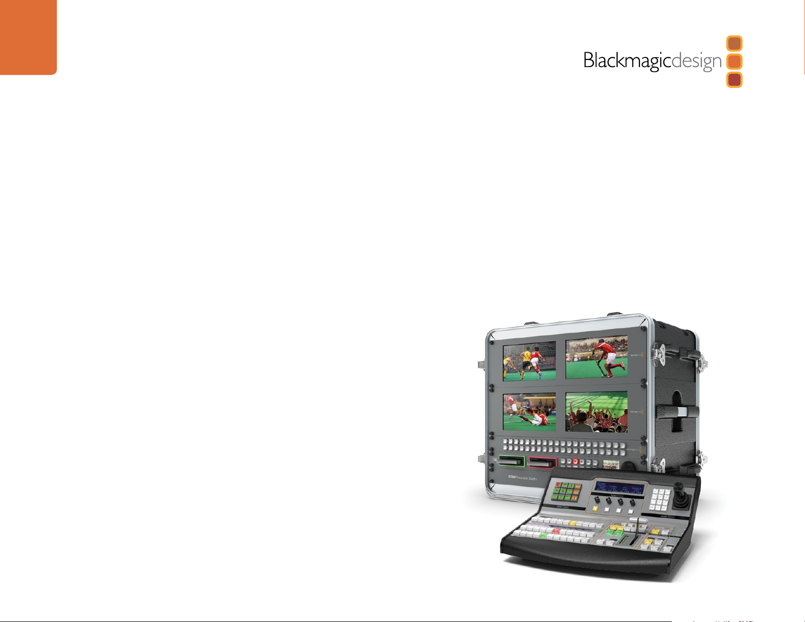
Blackmagicdesign ATEM Television Studio, ATEM Production Studio 4K, ATEM 1 M/E Production Studio 4K, ATEM 2 M/E Production Switcher Chassis Installation And Operation Manual
Page 1
Installation and Operation Manual
ATEM Production Switchers
Mac OS X
Windows
November 2013
™
™
Page 2
Welcome
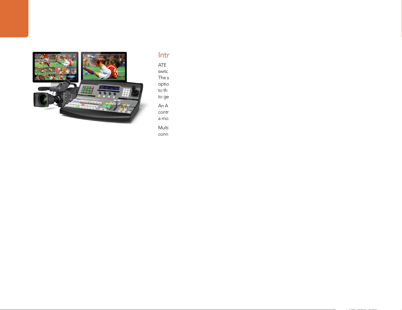
Welcome to ATEM Live Production!
Thank you for purchasing an ATEM switcher for your live production work!
If you’re new to live production switchers, then you’re about to become involved in the
most exciting part of the television industry and that’s live production! There is nothing
like live production and it’s so easy to become addicted to the adrenaline rush of editing
in real time while the live event unfolds before your eyes. It’s real television the way it
should be!
Previously broadcast quality live production has always been way too high in cost for
most people to afford, while affordable switchers lacked broadcast features and quality.
The new ATEM switchers change this, and you can use them for the most amazing
professional live production results. We hope you get years of use from them and have
lots of fun with your live production!
Not only do ATEM switchers include all the features and SDI connections that
broadcasters demand, but you also get HDMI connections so you can start with low cost
HDMI HD cameras and televisions. ATEM Production Studio 4K models even give you
Ultra HD 4K using HDMI and 6G-SDI connectors!
This instruction manual should contain all the information you’ll need for installing your
ATEM Production Switcher. The ATEM switcher includes a software control panel which
you can run on your computer or you can purchase a hardware based broadcast control
panel separately. The computer and control panels connect to your ATEM switcher via a
network cable and you can directly connect them together without any extra equipment!
Please check the support page on our web site at www.blackmagicdesign.com for the
latest version of software for your ATEM switcher. Simply connect your computer to the
ATEM switcher and the ATEM broadcast control panel via USB to update software so
you get all the latest features! When downloading software, please register with your
information so we can keep you updated when new software is released. We are constantly
working on new features and improvements, so we would love to hear from you!
Grant Petty
CEO Blackmagic Design
Page 3

Contents
ATEM Production Switchers
6
Getting Started
Introducing ATEM 6
What is an M/E Switcher? 6
What is an A/B Direct Switcher? 9
Understanding the ATEM Processor Chassis 10
Plugging in Multi View Monitoring 11
Plugging in a Control Panel 12
Installing Blackmagic ATEM Software on Mac OS X 13
Installing Blackmagic ATEM Software on Windows 14
Plugging in your Computer 15
Switcher Settings 16
Plugging in Cameras and Other Video Sources 17
Plugging in Audio and Other Audio Sources 18
Connecting to a Network 19
Changing the Switcher Network Settings 20
Understanding the Broadcast Panel Network Settings 20
Setting the Broadcast Panel to Find the Switcher IP Location 21
Changing the Broadcast Panel Network Settings 22
23
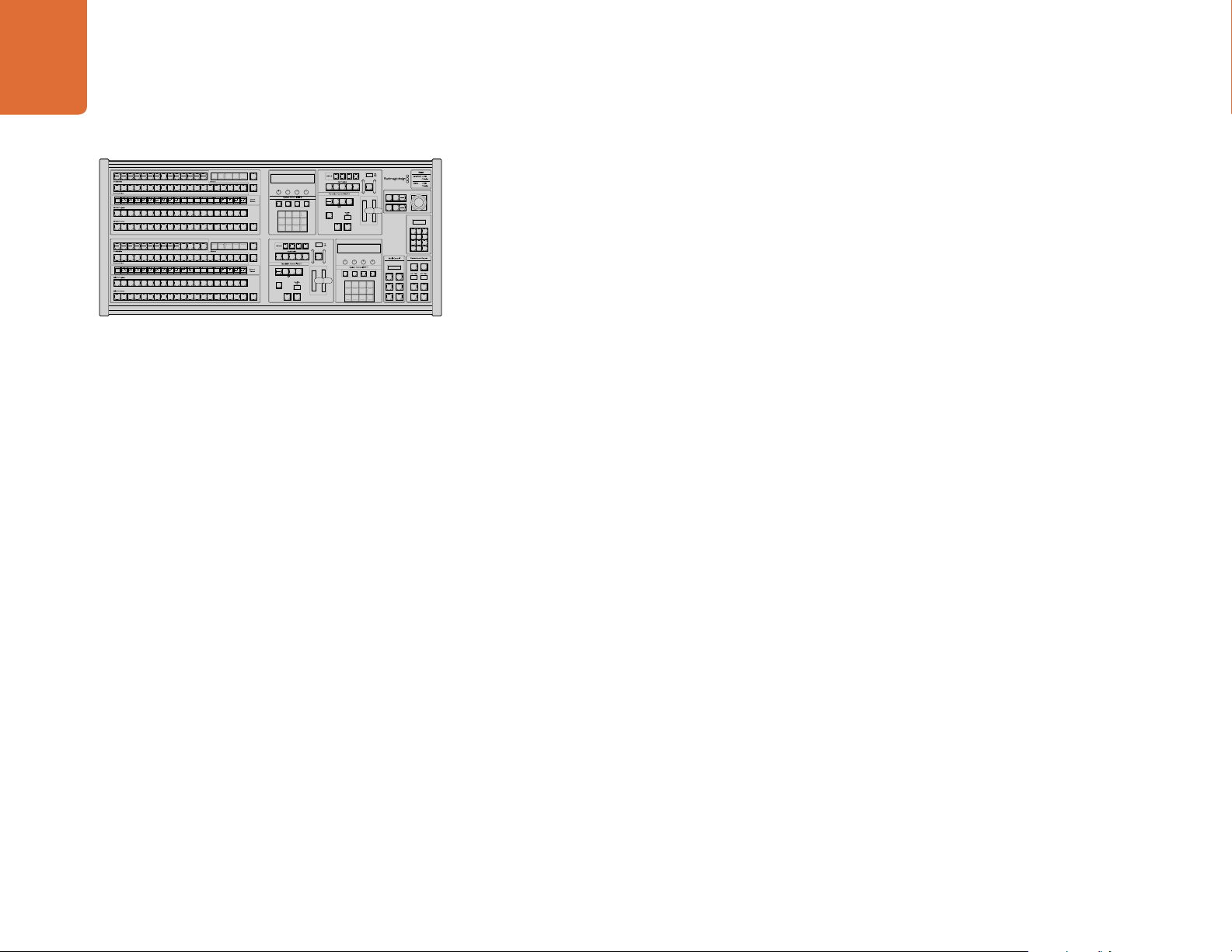
Updating the Software
How to update the ATEM Software! 23
Updating the Switcher Chassis Software 23
Updating the Broadcast Control Panel Software 24
25
27
Connecting Video Outputs
Using ATEM Software Control
Interface Overview 27
Switcher Control Panel 27
Audio Mixer 28
Media Manager 29
Switcher Settings 30
Using the Software Control Panel 30
Mix Effects 30
Program Bus Source Select Buttons 31
Preview Bus Source Select Buttons 31
Transition Control and Upstream Keyers 31
Downstream Keyers 33
Fade to Black (FTB) 33
Processing Palettes 33
Capture Palette 35
Using the Media Manager and Media Pool 37
Navigating the Browse Window 38
Changing Switcher Settings 39
Controlling Auxiliary Outputs 43
Button Mapping 44
Transition Control 44
Saving and Restoring Switcher Settings 44
Saving your Startup State 45
Page 4
Contents
ATEM Production Switchers
46
52
Using the ATEM 1 M/E Broadcast Panel
Control Panel Overview 46
Using the Control Panel 46
Mix Effects 46
Source Names Display 46
Program Bus 46
Preview Bus 47
SHIFT 47
Destination Display and Select Bus 47
Transition Control and Upstream Keyers 48
Downstream Keyers 49
Fade to Black 49
System Status 50
System Control 50
Menu Buttons 50
Joystick and Numeric Keypad 50
Button Mapping 51
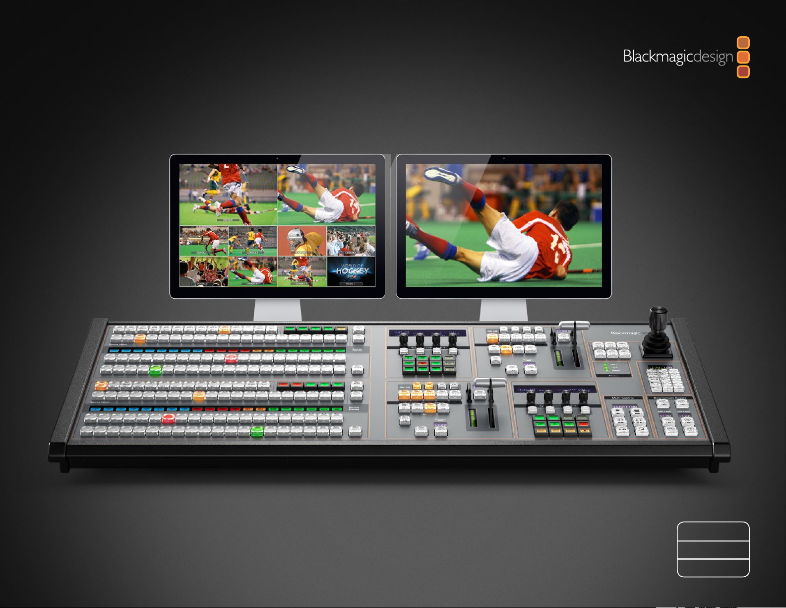
Using the ATEM 2 M/E Broadcast Panel
Control Panel Overview 52
Using the Control Panel 52
Mix Effects 52
Source Names Display 52
Program Bus 52
Preview Bus 53
SHIFT 53
Destination Bus and Select Bus 53
Auxiliary Outputs 54
Transition Control and Upstream Keyers 54
60
Downstream Keyers 55
Fade to Black 56
System Status 56
System Control 56
Menu Buttons 57
Joystick and M/E Pattern and Key Buttons 57
Joystick and Numeric Keypad 57
Button Mapping 58
Controlling Two ATEM Switchers 58
Operating your ATEM Switcher
Internal Video Sources 60
Black 60
Color Bars 60
Color Generators 60
Media Players 60
Cut Transitions 62
Auto Transitions 64
Manual Transitions 79
Preview Transition 79
Keying on ATEM Switchers 80
Understanding Keying 80
DVE Key 89
Adding DVE Borders 90
Using Adobe Photoshop with ATEM 96
Setting up Plug-in Switcher Location 96
Preparing Graphics for Download 96
Using Auxiliary Outputs 97
Using SuperSource (Picture in Picture) 100
Page 5
Contents
ATEM Production Switchers
103
105
111
112
120
Using Tally
Sending Tally Signals via a GPI and Tally Interface 103
Using Audio
Plugging in Audio and Other Audio Sources 105
Making Your Own Audio Breakout Cable 106
Using Embedded SDI and HDMI Audio Sources 108
Using a Third Party Audio Mixer Control Surface 109
Working with USB 3.0
Using Blackmagic Media Express
What is Media Express? 112
Capturing Video and Audio Files 113
Playing Back Video and Audio Files 117
Browsing Media 118
Using Blackmagic UltraScope
What is Blackmagic UltraScope? 120
Blackmagic UltraScope Interface 121
Understanding Blackmagic UltraScope Views 122
131
133
134
135
136
USB 3.0 Frequently Asked Questions
ATEM Television Studio Power Supply
Help
Warnings
Warranty
Page 6
6
Getting Started
Getting Started
Introducing ATEM
ATEM Production Switchers are professional broadcast grade digital production switchers capable of
switching and processing a variety of video sources in live video production and broadcast environments.
The switcher uses a current and familiar M/E (Mix Effects) based design with software and hardware control
options that provides a familiar, fast and easy to use workflow for program/preview switching! If you're used
to the older A/B direct switcher style, ATEM switchers also support A/B direct switching which makes it easy
to get started!
An ATEM production switcher only requires an ATEM production switcher chassis and the included software
control panel to get started. Then you can optionally add one or more hardware control panels if you need
a more advanced solution.
Multiple control panels can be connected to control the same switcher chassis by simple ethernet
connections. The ATEM software control panel can be installed on as many computers as you like at no
extra cost.
What is an M/E Switcher?
If you have used low cost switchers before, then these might not have used the mix effects style of operation
that’s commonly called an M/E style of operation. If you have used an M/E style switcher, then you might
want to skip ahead to install and get working with your new ATEM switcher!
When you’re starting out with a switcher for the first time, the ATEM can look a little intimidating with all its
buttons and knobs, however it's all very logically laid out so it's very simple to use!
ATEM is a true high-end broadcast switcher that operates using the M/E workflow standards used in the
broadcast industry. This means once you get familiar with how it works, you will feel instantly at home on
virtually any switcher used in broadcast today.
The M/E style of operation has been developed over decades to help eliminate errors when switching live
events and is a broadcast standard. It's extremely easy to see what's going on at any time so you don't get
confused and make mistakes. The M/E style of operation lets you check the sources you are about to switch
on air, as well as try effects before using them on air. You can see buttons for each keyer and transition, so
you instantly know what's going on and what's about to happen.
The best way to learn about how your ATEM works is to grab your switcher and play with it while referencing
this manual! You might want to jump ahead and install your switcher before reading the rest of this section!
To start, the most visible part of an M/E based control panel is the fader bar, and the program and preview
rows of source buttons!
Page 7

7
Getting Started
The program bus source select buttons are used to hot switch sources to the program output. The source
currently on air is indicated by a button that is illuminated red. Be careful when selecting sources on this row,
as they will instantly be switched on air!
A better and more orderly way to do transitions is to select them on the preview row, and then use a
transition to cut or transition them on air.
The bottom row of buttons is the preview bus source selection. This is where you will spend most of your
time selecting sources about to go on air. This selected source is sent to the program output when the next
transition occurs. The next transition can be triggered by pushing the cut button, the auto button, or by
toggling the fader bar. You can select between a mix, dip, wipe, DVE or other transition depending what
you have selected in the transition control section.
This is a very powerful way to use a switcher, because you can select your source on the preview row, and see
it on the preview video output to confirm that you have the correct source before you select the transition
you want. You can see what's happening at all stages so it’s hard to make mistakes. Only the M/E style of
operation allows you to keep track of what's going on.
You also might notice that once your transition is complete, the sources selected on the preview and
program rows swap over. This is because the source you selected on the preview row is now the new on
air source, so it becomes selected on the program row once the transition is complete. Remember the
program row always shows what's on air.
You will also see both the program and preview buttons illuminate red when doing an auto transition, as for
a short time, they are both on air while the transition occurs.
There are multiple types of transitions available, and they can be selected in the transition control. On the
ATEM 1 M/E Broadcast Panel there are two transition type buttons. One is labeled mix/dip and the other
is labeled DVE/wipe. Selecting these buttons selects mix and wipe transitions, however pressing shift and
then selecting mix or wipe allows more types of transitions, dip and DVE. You can also select both buttons
for a stinger transition. On the ATEM 2 M/E Broadcast Panel there are four transition type buttons. One is
labeled mix/dip and the others are labeled wipe, stng and DVE. Selecting these buttons selects mix, wipe,
stinger and DVE transitions. However pressing shift and then selecting mix allows for dip transitions. If you
are using the ATEM software control panel on your computer, all transition types have their own button, and
no shifting is necessary to select any of them. Extra details on how all these transitions work are provided
later in this instruction manual.
Page 8

8
Getting Started
The other concept that is important to know about M/E style switchers, including ATEM, is the video on the
program and preview rows is technically called the background video. This is because the upstream (effects)
keyers and downstream keyers will overlay on top of this source. So you can load graphics into the keyers
and see them with the preview video and when keys are turned on, you will see the overlay on top of the
program video. This is very powerful and allows multiple layers to be built up.
Another great advantage of the ATEM M/E style of operation is you can tie keyers to the transition. This
means when you do a mix transition, you can also fade on or off keyers at the same time. This allows you to
build up a composition, and then bring the whole lot on air at the same time. This is what the next transition
buttons do, and you can select background for normal transitions, or select one or more keyers to transition
them on air.
You can even press multiple buttons on the hardware control panel to tie multiple keys and the background
at the same time. There are also dedicated downstream key tie buttons to tie downstream keyers to the
transition. Downstream keys also have dedicated cut and mix buttons and so are very flexible. Downstream
keyers are always layered over the top of everything including the transition, so are a great place to key bugs
and logos!
Finally, when your live production is finishing, it's nice to have a dedicated fade to black (FTB) control to fade
everything to black! You can see the dedicated fade to black control on the right side of the keyboard. This
lets you fade everything to black, and helps make sure you don't miss a layer. Fade to black is at the extreme
end of the processing chain so you get a clean fade of all sources.
The last part of an M/E style switcher is the select bus. This is above the program row, and simply allows
sources to be selected for effects processing and other purposes, and there is a label above this to show
what you’re switching. The select bus is commonly used to select key inputs, and aux outputs. It's a clean
switch, so when used to select aux outputs, you get a clean cut.
As you can see by this quick overview, M/E style of operation allows confident live production with good
feedback on what's going on and the state of your switcher and programming at any point in your production.
Once you learn the M/E style of operation, you can move between models of production switchers with little
retraining as they all work the same!
Page 9

9
Getting Started
What is an A/B Direct Switcher?
If you have been using video switchers for a long time, then you might be used to older-style A/B direct
switchers and you can easily set your ATEM switcher to A/B direct switching in the ATEM software preferences.
See the Transition Control section of this instruction manual for details about where to change this setting.
A/B direct switchers have an A bus and a B bus. One bus is the program bus which shows a red button for
the current program output. The other is the preview bus which has a green button for the preview video.
As you move the fader bar up and down, the buses switch so that the red program button follows the fader
handle. This is where A/B direct switching is really easy to use as the buttons stay lit in the same positions
and just switch color between green and red.
A/B direct switching becomes a little more confusing when the fader bar is not used to make the switch.
If you use a cut or auto transition button to bring your preview source on air, or if you use more than one
control panel connected to your switcher, the fader bar won't have moved on the control panel that you are
using. The red program output always follows the fader bar handle and, as you haven't moved it, the red
program light has to move to another button on the same row and the green preview light has to move to
another button in its row.
This can become quite confusing when sometimes using the fader bar to make switches, and sometimes
not, as the rows containing your preview and program buttons will sometimes switch and sometimes stay
where they are which has the potential to lead to mistakes.
This is why modern M/E style switching is preferable because you'll always find your green preview button
in the row labelled Preview, and the red program button in the row labelled Program. It's always consistent
and there are no surprises with M/E style switching.
Page 10
10
Getting Started
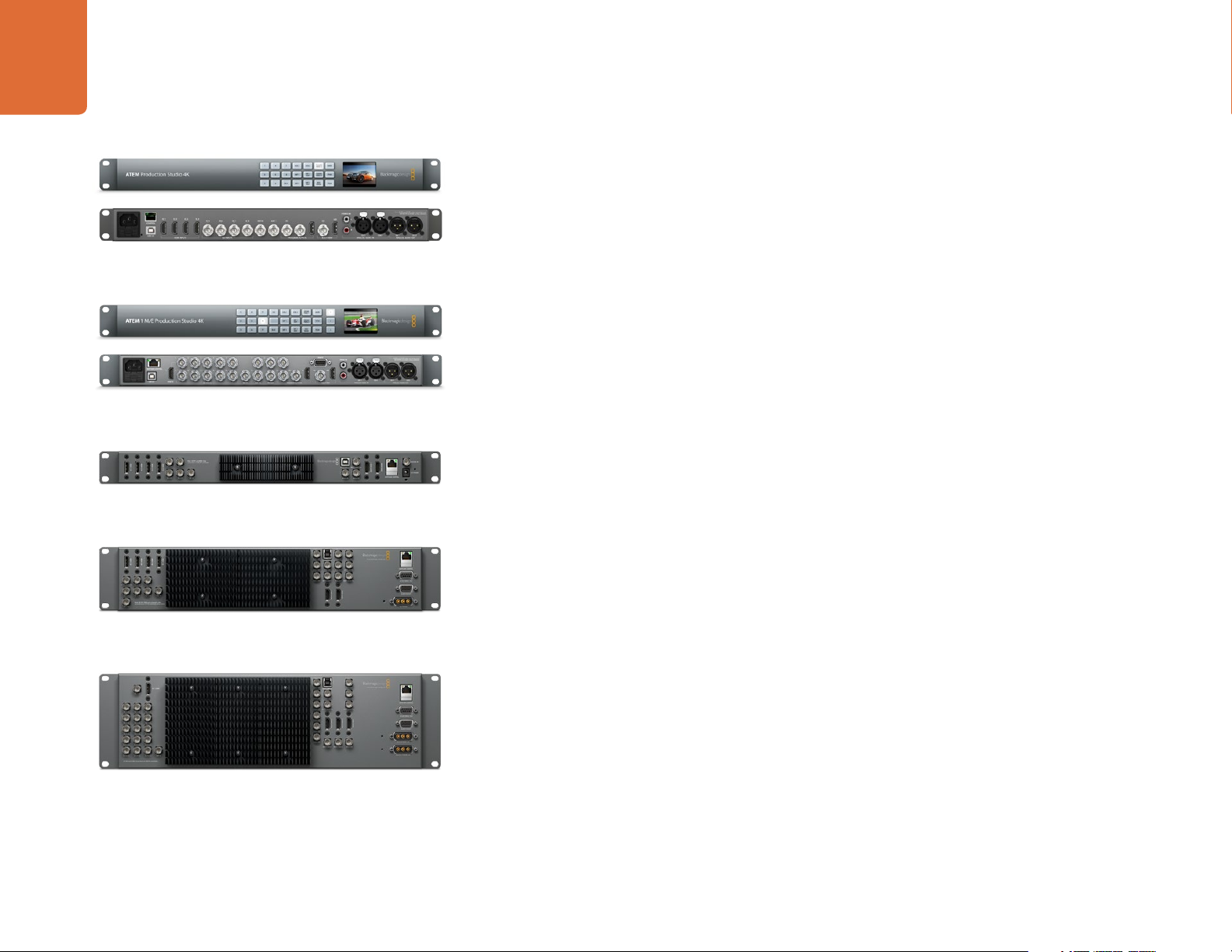
ATEM Production Studio 4K
ATEM 1 M/E Production Studio 4K
ATEM Television Studio
Understanding the ATEM Processor Chassis
The ATEM processor chassis provides all the video processing as well as all video input and output
connectors, connection for control panels and power connections. You use the ATEM switcher by
connecting and using various types of control panels. This allows the switcher to be located remotely,
such as in machine rooms where it's closer to the connected video devices, while the control panel can be
placed in a location from where it is easier to run production.
ATEM Production Studio 4K supports SD, HD and Ultra HD 4K video and is capable of switching 8 external
inputs from its SDI and HDMI connectors. The front panel keypad lets you select instantly between auxiliary
output sources and the small LCD gives you instant feedback on the status of the auxiliary output.
ATEM 1 M/E Production Studio 4K supports SD, HD and Ultra HD 4K video and is capable of switching 10
external inputs from its SDI and HDMI connectors. Input 1 is selectable between the HDMI Input 1 and SDI
Input 1 connector. The front panel keypad lets you select instantly between 3 auxiliary output sources and
the small LCD gives you instant feedback on the status of the auxiliary outputs.
ATEM Television Studio supports SD and HD video and is capable of switching 6 external inputs from its SDI
and HDMI input connectors. Inputs 3 and 4 are selectable between HDMI and SDI, which can be set in the
ATEM software control panel settings tab.
ATEM 1 M/E Production Switcher supports SD and HD video and is capable of switching 8 external inputs
from its analog, SDI and HDMI input connectors. Input 1 is selectable between the HDMI Input 1 connector
and the analog component Input 1 connector and is set in the ATEM software control panel settings tab.
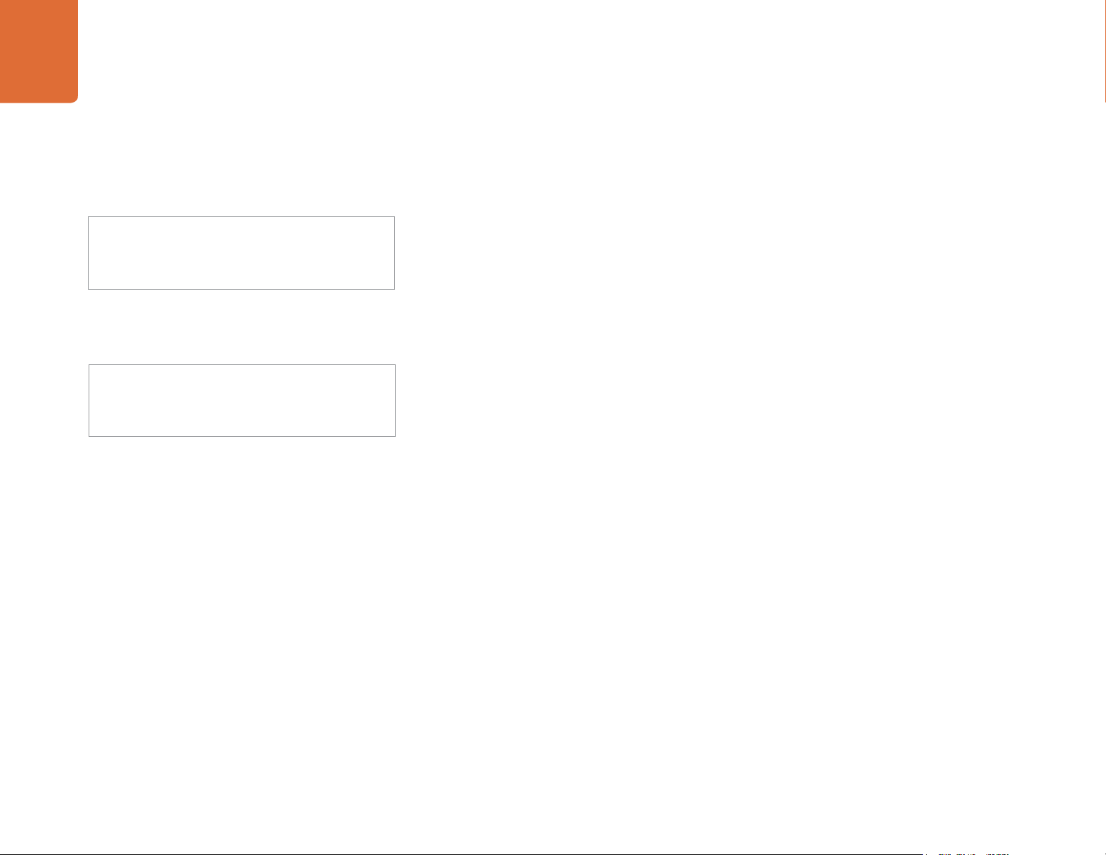
ATEM 1 M/E Production Switcher Chassis
ATEM 2 M/E Production Switcher Chassis
ATEM 2 M/E Production Switcher supports SD and HD video and is capable of switching 16 external inputs
from its SDI and HDMI input connectors. Input 1 is selectable between the HDMI Input 1 connector and the
SDI Input 1 connector and is set in the ATEM software control panel settings tab.
The ATEM chassis mounts in a standard 19" rack. The Television Studio and Production Studio 4K model
switchers are only 1 rack unit high, while the 1 M/E and 2 M/E Production Switchers are 2 rack units and 3
rack units high respectively. The ATEM chassis is very thin and ideal for either fixed installation or portable
use. Production Switcher models can mount to the front or back of a rack to save space.
When running an ATEM model with an external heat sink, you might notice the ATEM processor chassis
feels warm to the touch. This is because the internal microprocessors are connected to the rear mounted
heat sink via the metal chassis. This causes heat to spread out over the metal chassis, however your ATEM
chassis is not overheating. The Production Studio 4K models have a deeper chassis with internal cooling
fans rather than an external heat sink.
Page 11
11
Getting Started
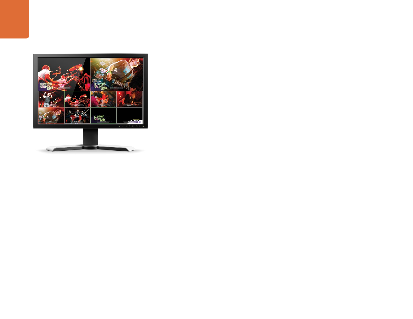
Plugging in Multi View Monitoring
The ATEM switcher chassis can be a little intimidating when first seen, because most models have no
controls to access, just lots of connectors! So the first step is to plug in the power, and a monitor, to see it
working! The ATEM Production Studio 4K models have a front control panel with a built in LCD so you only
need to connect power to see them working!
A fantastic way to check that your ATEM is powered on and working correctly is to plug an HDMI television
into the Multi View output on the right side of the rear panel. You should see 8 video boxes at the bottom,
and two larger boxes at the top, all bound by white borders. Each box will have a label.
If you see this video output, then your ATEM switcher is powered on and running fine! All you need to do
now is plug in some control panels and video sources so you can start using your switcher!
If you don't see the Multi View output on your television, check the connections and cables are correct. You
need to plug into the Multi View connector on the rear of the ATEM chassis. Next check your television is
compatible with 1080 59.94i video, as your ATEM switcher defaults to that video standard when new. If your
television is not compatible with 1080 59.94i, then don't worry, it's easy to change once we connect your
computer to the ATEM chassis.
If you still don't see the Multi View on your television, then double check your power connection to make
sure your ATEM is powered on.
Page 12
12
MAIN 12V POWERBACKUP 12V POWER
USB 2.0
ETHERNET 2 ETHERNET 1
MAIN 12V POWERBACKUP 12V POWER
USB 2.0
ETHERNET 2 ETHERNET 1
Getting Started
Plugging in a Control Panel
If you have purchased an ATEM Broadcast Panel, then you won't want to wait to plug in your computer, as
it's much more fun to plug in the hardware panel first!
USB 2.0
MAIN 12V POWERBACKUP 12V POWER
ETHERNET 2 ETHERNET 1
ATEM 1 M/E Broadcast Panel rear connectors
MAIN 12V POWERBACKUP 12V POWER
USB 2.0
ETHERNET 2 ETHERNET 1
ATEM 2 M/E Broadcast Panel rear connectors
Plugging in the ATEM Broadcast Panel is simple, because it's already set to the correct network settings to
plug into your ATEM processor chassis without any changes required.
Step 1. Plug in the power to the ATEM Broadcast Panel. If you want redundant power supplies, then you
can purchase a second power supply and plug that into the second power connector.
Step 2. Plug one end of an ethernet cable into one of the control panel’s ethernet ports. Either of the
ports will do, as there is an ethernet switch inside the panel, so both ports work the same.
Step 3. Plug the other end of the same cable into the ethernet port on the ATEM processor chassis
labeled switcher control.
If everything is working fine, you should see the lights on the ethernet port start to flicker, and the
panel should come alive with buttons illuminated, and the main display on the panel should say ATEM
Production Switcher.
If you don't see this appear, then check the ATEM processor chassis and the control panel are powered
correctly and the cables are screwed in tight.
If things are still not working, then you should make sure you are not plugged into a network, and that your
panel is connected directly to your ATEM switcher processor chassis. If this is correct, then the most likely
cause of the problem is the switcher and the chassis have IP addresses in different ranges to each other. In
this case, you will need to check and set these as described later in this manual.
If you need to manually set the network settings, then you might need to get the assistance of a technically
minded friend who understands how to set IP addresses. By default, the ATEM processor chassis is set to a
fixed IP address of 192.168.10.240, and the ATEM Broadcast Panel is set to fixed IP of 192.168.10.10, so when
connected directly they should communicate without any problems. Go to the connecting to the network
section in this manual to see how to check and set your switcher to these addresses. Then it should work OK
with a direct connection between the panel and the switcher processor chassis.
Page 13
13
Getting Started
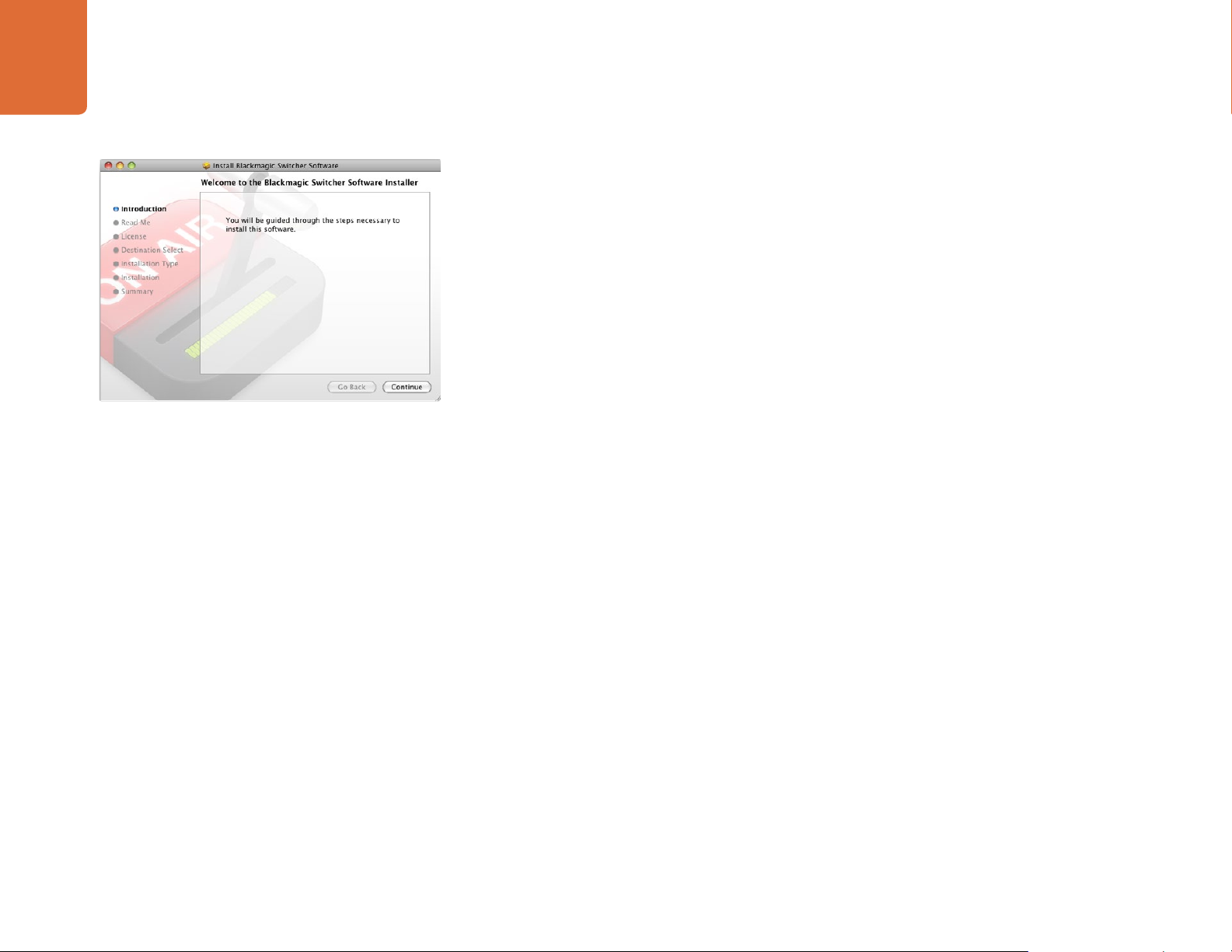
Follow install prompts.
Installing Blackmagic ATEM Software on Mac OS X
Before installing any software you will need administrator privileges.
Step 1. Ensure you have the very latest driver. Visit www.blackmagicdesign.com/support
Step 2. Open the “Blackmagic ATEM Switchers” folder from the disc or downloaded disk image and
launch the “Blackmagic ATEM Switchers Installer”.
Step 3. Click Continue, Agree and Install buttons and the software will be installed on your system.
Step 4. Now restart your computer to enable the new software drivers.
Plugins and Applications that are Installed
The ATEM Switchers software installs the following components which are used by ATEM Switchers:
ATEM Software Control
ATEM Setup Utility
Blackmagic Desktop Video drivers
Blackmagic Media Express
The ATEM Switchers software also installs additional Blackmagic Desktop Video components which are
used by other Blackmagic Design capture products when installed on the same computer:
On Mac OS X, all the files needed to run your ATEM switcher will be installed into a folder called Blackmagic
ATEM Switchers in the Applications folder.
In this Blackmagic ATEM Switchers folder, you will see ATEM Software Control, which is the software control
panel for your switcher, and also allows loading graphics into the switcher media pool and changing settings.
The ATEM Setup Utility allows you to change the switcher IP address, or update the switcher and panel
software via USB. Also included in this folder is this instruction manual and some example graphics. Use the
example graphics to explore the internal media pool and keying functionality.
In the Applications folder, you will see Blackmagic Media Express which allows you to capture the Program
Output of ATEM Television Studio to H.264 files.
Page 14
14
Getting Started
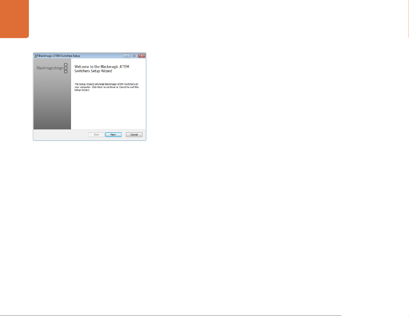
Installing Blackmagic ATEM Software on Windows
Step 1. Ensure you have the very latest driver. Visit www.blackmagicdesign.com/support
Step 2. Open the “Blackmagic ATEM Switchers” folder and launch the “Blackmagic ATEM Switchers
Installer”.
Step 3. The software will now be installed on your system. An alert will appear: “Do you want to allow the
following program to install software on this computer?” Click Yes to continue.
Step 4. You will see a dialog bubble saying “found new hardware” and the hardware wizard will appear.
Select “install automatically” and the system will find the required Desktop Video drivers. You will
then receive another dialog bubble saying “your new hardware is ready for use.”
Step 5. Now restart your computer to enable the new software drivers.
Follow install prompts.
Plugins and Applications that are Installed
The ATEM Switchers software installs the following components which are used by ATEM Switchers:
ATEM Software Control
ATEM Setup Utility
Blackmagic Desktop Video drivers
Blackmagic Media Express
Blackmagic UltraScope
The ATEM Switchers software also installs additional Blackmagic Desktop Video components which are
used by other Blackmagic Design capture products when installed on the same computer:
Once the computer has restarted, all the ATEM software applications will be installed and can be accessed
from Start > Programs > Blackmagic Design.
In the ATEM Switchers folder, you will see the ATEM Software Control, which is the software control panel for
your switcher, which also allows loading graphics into the switcher media pool and changing settings. The
ATEM Setup Utility allows you to change the switcher IP address, or update the switcher and panel software
via USB. Also included in this folder is this instruction manual and some example graphics. Use the example
graphics to explore the internal media pool and keying functionality.
In the Media Express folder, you will see Blackmagic Media Express which allows you to capture the
Program Output of ATEM Television Studio to H.264 files. Media Express also allows you to capture the
uncompressed Aux 1 output of ATEM 1 M/E and 2 M/E Production Switchers via USB 3.0, which is perfect for
post production. In the UltraScope folder, you will see Blackmagic UltraScope which allows you to perform
live waveform monitoring of the Aux 1 output of ATEM 1 M/E and 2 M/E Production Switchers via USB 3.0.
Page 15
15
Getting Started
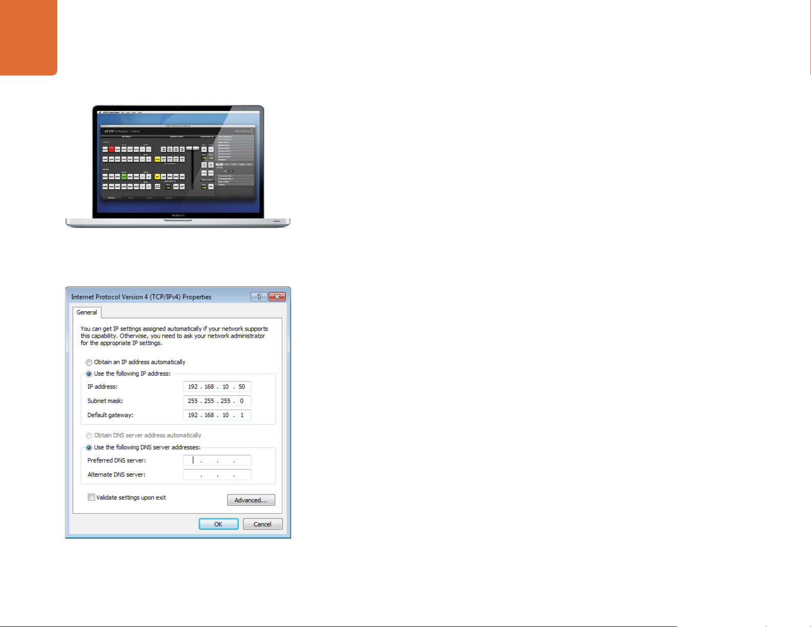
Plugging in your Computer
You can plug your computer directly into the ATEM switcher so you can control the switcher, load the media
pool with graphics and clips, and change switcher settings.
You will need to connect a computer otherwise you cannot change settings such as the switcher video
standard, as well as downconversion modes, input video connections and labels, as well as customizing the
Multi View.
Connecting your computer is easy and after installing the ATEM Switcher Software simply follow the
directions below:
Step 1. Connect an Ethernet cable from the chassis ethernet port labeled Switcher Control to the Ethernet
port of your computer.
If you have a hardware panel installed, and already have this connected to your ATEM, then plug
your computer into the second ethernet port on your hardware panel instead. Now the computer
will talk via your panel to the switcher, and both the hardware panel and this software control
panel can be operated in parallel.
Step 2. Ensure your ATEM switcher is powered on.
Step 3. In the network settings on your computer, enable ethernet, and set the IP address setting to
manual. Then enter the IP address 192.168.10.50.
Set IP Address for your Computer
Now when you run your ATEM Software Control you should see the buttons on the control tab light up and
show the switcher state after a slight pause.
If you’re more technically minded and want to connect your ATEM switcher to your existing network, then
you will need to change the network settings on your ATEM switcher and control panel. Information on how
to do this is available in the next section. You will need to manually set the IP address for the switcher chassis
as well as all control panels to match your network IP address range. Your ATEM switcher defaults to a fixed
IP address of 192.168.10.240 when shipped and, by using the ATEM Setup Utility, you can customize the IP
address for your custom network configuration.
Page 16
16
Getting Started
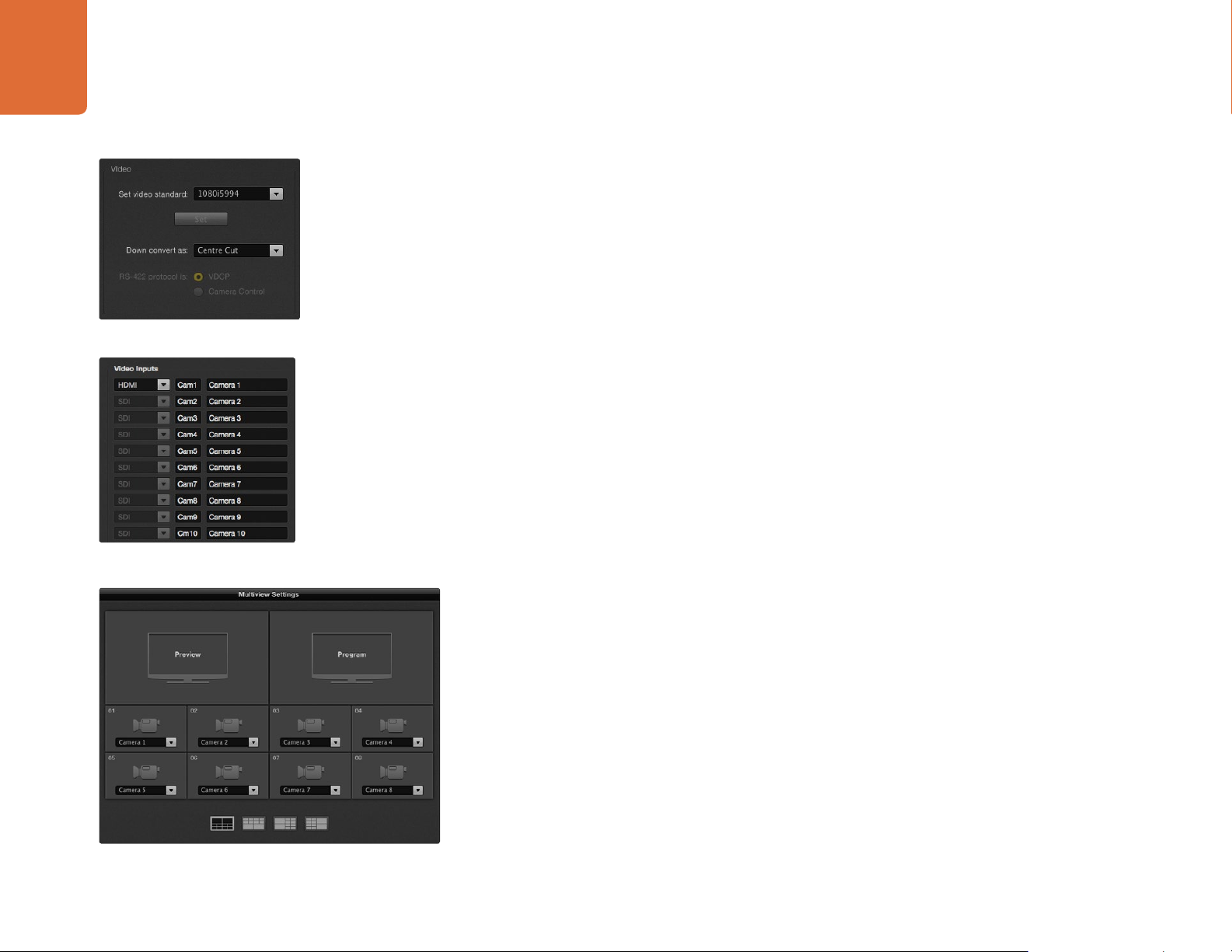
Set Video Standard
Set Video Inputs and Labels
Switcher Settings
Now you have the software control working, you'll need to apply your switcher settings. Settings are made
in the settings tab of the ATEM Software Control and the most critical settings are listed below.
Set the switcher video standard
ATEM defaults to 1080 59.94i when purchased, however you might want to select another video standard if
you’re working in Europe or Asia. 1080 59.94i, 720 59.94p and NTSC is common in the US and Japan, while
in Europe and Asia, 1080 50i, 720 50p, or PAL is more common.
If you're working with standard definition video equipment in the widescreen anamorphic 16:9 video format,
select 525 59.94i 16:9 for anamorphic NTSC or 625 50i 16:9 for anamorphic PAL.
Make sure all your cameras and any connected HDMI devices are also set to the same video standard, or
they won't be visible on the switcher video inputs. This is generally quite easy, as countries have standards
for their HD broadcasts and all equipment sold in these countries matches this standard or at the very least
can be switched between standards. When all video standards are matched, you should see connected
devices show up in the multi view video input windows.
Set and label the video input settings
Different models of ATEM switchers allow some inputs to share connections on the rear panel. For example
on the ATEM 1 M/E Production Studio 4K model, input 1 can be switched between HDMI and SDI.
While you’re setting inputs, you might also want to change the input labels. These labels appear on the
Multi View and the hardware panel. There are two labels to change: a long label used in software, and the
short label that's limited to 4 digits and used in the hardware control panel.
Customize the Multi View
Customize the multi view
There are 8 input views in the multi view, and you can select from a range of external and internal sources
to display on these views. Simply click the menus to select what you want on each view. If you don't have
8 cameras on your job, then you can even select media players, color generators, or aux outputs on these
views. It's extremely flexible, and you can also change the multi view layout to suit your preference.
Select the Control Panel
You can use the M/E 1 Control Panel with any ATEM switcher. The panel is compact enough to fit on smaller
displays including on notebooks. If you have an ATEM 2 M/E Production Switcher and a 1920 x 1080 or
larger computer display, you can use the full size M/E 2 Control Panel to see the full set of buttons at once.
Simply select your preferred panel from the Window menu.
Page 17
17
Getting Started
Plugging in Cameras and Other Video Sources
Now you’re ready to plug in cameras! All you need to do is connect a cable from the camera video output,
either HDMI or SDI, and then connect it to an input on the ATEM switcher chassis.
Each connector on the rear chassis has an input label so you can see what camera is what input when viewed
on the Multi View and the control panel. If all your cameras are using the same video standard as set in your
switcher, you will see each camera appear as you plug them in.
You don't need to worry about genlock for cameras, because each input of your ATEM switcher has a full
frame resynchronizer. If the ATEM switcher detects that a video source is out of sync, it will automatically
enable the frame sync so the input is clean for use. The frame sync function also allows consumer cameras to
be connected to your ATEM, and using consumer cameras is a great way to get started because the latest
HDMI based consumer HD cameras are now very affordable, and give quite nice HD. This lets you spend
your money on more cameras, and then as you grow, you can start adding professional SDI based cameras.
If you’re plugging a computer with HDMI compatibility into the HDMI inputs of the ATEM switcher, then
be sure that the monitor settings on the computer are set to the correct resolution and frame rate. If you’re
using 1080i video, then your monitor needs to be 1920 x 1080 resolution. If you’re running 720p on your
switcher, then your monitor needs to be set to 1280 x 720 resolution. If you are using NTSC then your
monitor needs to be 720 x 486. If you are using PAL then your monitor needs to be set to 720 x 576. The
frame rates also need to match.
It's important to know that HDMI cable quality can vary, so we recommend buying good quality cables, and
high end video resellers will stock a range of high quality cables. Good quality cables will help eliminate
unwanted sparkle or glitches in HDMI video inputs.
If you don't see video on a HDMI video input, even though you have a device connected, then you might
want to check if the HDMI device you have connected uses HDCP content protection. This content
protection actually encrypts the video data in the HDMI video cable, so the manufacturer does not allow
the content to be seen on anything other than a television. You won't be able to see images from these
devices. Devices with HDCP content protection include DVD payers, and set top boxes.
In general, cameras and computers don't have content protection, so you should not have any problems
connecting these devices. Some gaming consoles don't include HDCP content protection, however
generally these are only the developer versions of these gaming consoles. Using the analog component
input of a Mini Converter Analog to SDI or the analog component input on an ATEM 1 M/E Production
switcher to connect devices is a good work around in these situations.
Please always be sure you have copyright ownership before using content, or displaying content publicly.
Page 18
18
BACKUP POWER 12V
MAIN POWER 12V
AUDIO IN/OUT
RS-422 SERIAL OUT
SWITCHER CONTROL
AES/EBU IN
12V POWER
Getting Started
Note: All SDI and HDMI video
connections are SD/HD switchable.
IN 3 SDI IN 5 SDI
IN 1 HDMI
IN 2 HDMI
IN 3 HDMI
IN 4 HDMI
IN 4 SDI IN 6 SDI
REF IN
ATEM Television Studio has an AES/EBU digital audio input
PROG USB 2.0
MULTI-VIEW SDI
PROG HDMI
MULTI-VIEW 1
SWITCHER CONTROL
PROG SDI
PROG SDI
Plugging in Audio and Other Audio Sources
All ATEM switchers include a built in audio mixer which allows any switcher to use embedded HDMI and
SDI audio from your cameras as well as external audio from the dedicated audio input. The audio input
can be used for audio sources which might not have been embedded in a video signal, such as camera
microphones and pre-recorded audio.
ATEM Production Studio 4K models feature standard balanced XLR audio inputs and outputs, and
unbalanced RCA audio inputs so you can connect your external audio source directly. RCA audio
AES/EBU IN
12V POWER
connectors are useful when using audio from consumer equipment such as a HiFi system or iPod. XLR
audio connectors are balanced and provide the best quality. Balanced connectors are designed to reduce
any potential interference and noise, and are also important when long cable lengths are required.
If you're using an ATEM Television Studio with an external digital audio source, such as a digital microphone
or mixer, you can connect the AES/EBU audio output of the source directly to the AES/EBU IN port on the
switcher. Otherwise use an inexpensive A/D converter, such as the Behringer SRC2496, to take the analog
audio output of your audio source and convert it to AES/EBU audio for your switcher.
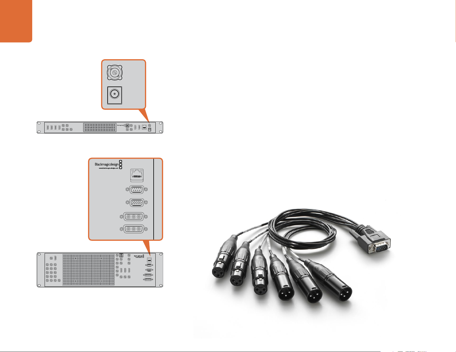
If you have an ATEM 1 M/E or 2 M/E Production Switcher, you can use the included breakout cable or
make your own custom breakout cable to connect your external audio source's professional, balanced,
analog audio output to the switcher.
AUX 1 SDI
IN 1 HDMI
IN 1 SDI
IN 2 SDI IN 3 SDI IN 4 SDI
IN 5 SDI IN 6 SDI IN 7 SDI
IN 8 SDI IN 9 SDI IN 10 SDI
IN 13 SDIIN 12 SDIIN 11 SDI
IN 16 SDI REF ININ 15 SDIIN 14 SDI
All SDI and HDMI connections are SD/HD switchable.
ATEM 1 M/E and 2 M/E Production Switchers have an audio
AUX 2 SDI
AUX 3 SDI M/E 2 PROG SDI
AUX 4 SDI
AUX 5 SDI
AUX 6 SDI
AUX 1 USB 3.0
PREV SDI
MULTI-VIEW 1 MULTI-VIEW 2
MULTI-VIEW 1
in/out port which connects to an analog audio breakout cable.
PROG SDI
PROG SD-SDI
PROG NTSC/PAL
MULTI-VIEW 2
PROG SDI
SWITCHER CONTROL
RS-422 SERIAL OUT
PROG HDMI
AUDIO IN/OUT
MAIN POWER 12V
BACKUP POWER 12V
The audio breakout cable included with ATEM 1 M/E and 2 M/E Production Switchers connects to the AUDIO IN/OUT port.
Page 19
19
Getting Started
Connecting to a Network
If you want to connect your ATEM switcher to a larger ethernet network, then you will most likely need
to change the network settings on your ATEM switcher. Most people simply plug their computer and
control panel direct to the ATEM chassis, however in some situations it can be very powerful to connect
via your network!
Your ATEM ships from the factory with settings to allow hardware control panels to simply be connected
directly with an ethernet cable. However your ATEM supports full ethernet IP protocols so you can place
your switcher and panel on your network or anywhere on the planet using the internet.
However it's worth noting that if you use your ATEM on a network, then you’re also increasing the complexity
of the connection between your control panel and the switcher, so there is possibly a greater chance of
something going wrong. However ATEM can be used when plugged into a switch, and even via most VPNs
and over the internet.
To allow communication over ethernet, the IP addresses of the switcher chassis, broadcast panel and any
computer's running the ATEM Software Control Panel need to be configured correctly. The IP address used
for each device will depend on the IP address range of the network you’re plugging into.
The ATEM switcher chassis always needs a fixed IP address so control panels have a stable location to
connect to. This means you need to find a free fixed IP address in the range of your network that you
can use.
The control panels can be set to DHCP or fixed IP addresses. Generally when used on a network, the
control panel would be selected to DHCP, so it is automatically assigned an IP address when connected to
the network.
For all devices to communicate, they must share the same IP address subnet, which typically means the first
3 fields in the IP address need to be the same. Each device must also use a unique IP address.
Please remember to set all devices to the correct IP address so they can all communicate. You will need to
set the IP address of the ATEM Production Switcher via USB using the ATEM Setup Utility. You will need to
set the DHCP or fixed IP mode on the ATEM Broadcast Panel and if using a fixed IP address on the panel,
set the IP address on the panel. You will also need to set the panel, switcher address to the new IP address
you have just set for the switcher.
Lastly, you need to ensure your computer is connected and working on your network. Then when you launch
the ATEM Software Control application, you will be prompted automatically to enter in an IP address for
the switcher if ATEM Software Control cannot communicate with the ATEM processor chassis. Use the IP
address you just entered in for the switcher processor chassis. Then the ATEM Software Control can find the
switcher and communicate.
Page 20
20
Getting Started
Changing the Switcher Network Settings
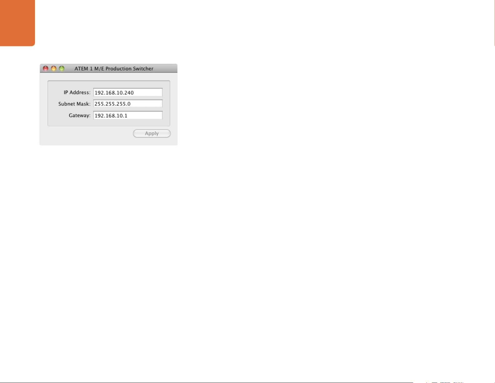
The switcher network settings are changed using the ATEM Setup Utility via USB. Please follow the steps
below:
Step 1. Connect the switcher chassis via USB, to the computer running the ATEM Setup Utility software.
Step 2. Launch the ATEM Setup Utility software.
Step 3. The switcher's current IP address and other settings will be displayed in the window. If you only
want to check the IP address and not change it, you can simply quit ATEM Setup Utility.
Step 4. To change the IP address or any other settings, simply edit the numbers and then select apply.
ATEM Setup Utility Connects via USB
Step 5. A dialog box will prompt you to please power cycle your ATEM switcher. Turn off and on the
power on the switcher and then press OK.
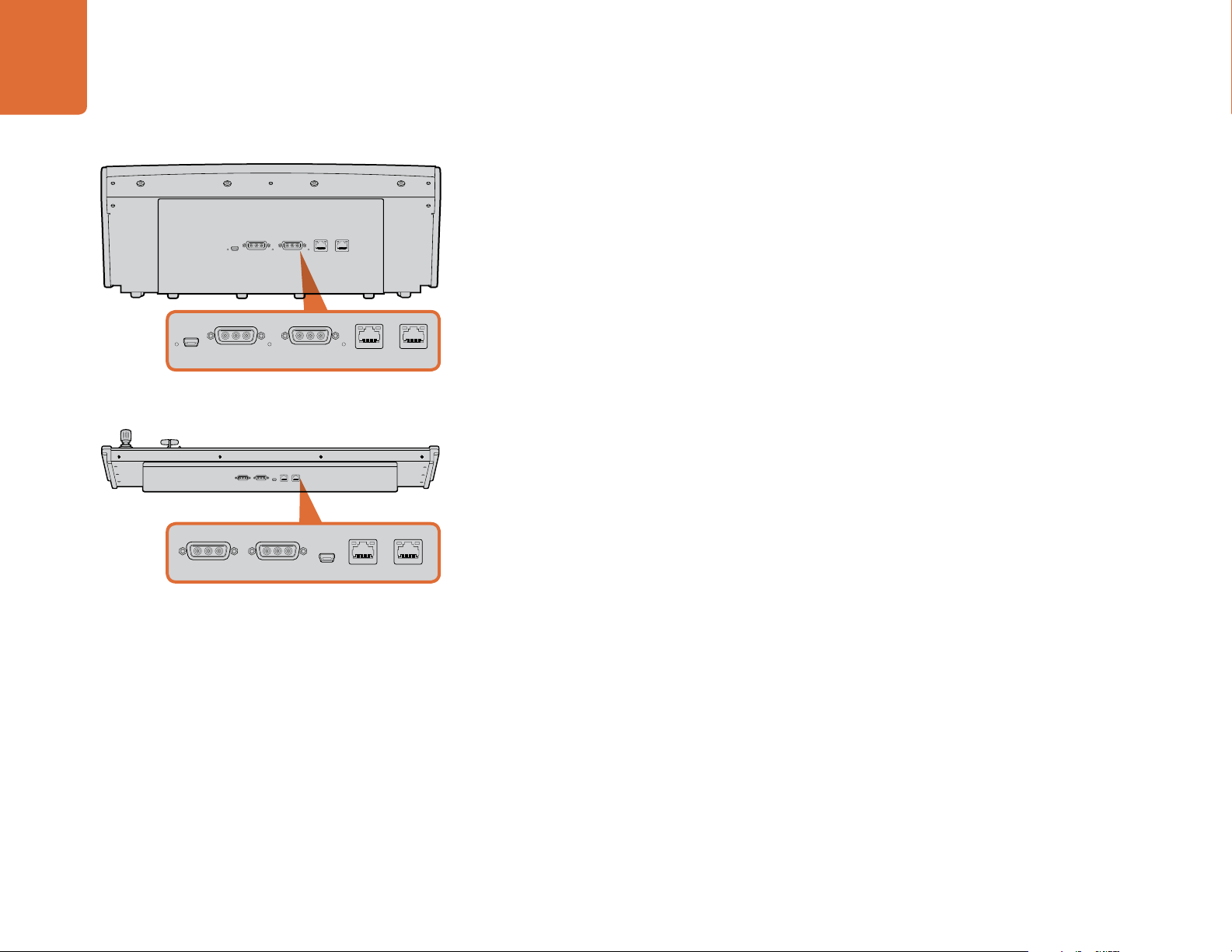
Understanding the Broadcast Panel Network Settings
A broadcast panel's network settings are configured from the network setup menu in the broadcast panel's
system control. Along with its own IP address, the broadcast panel also needs to be configured with the
network location of the switcher, so that communication between the two devices can be established over
the ethernet connection. If the broadcast panel's network settings are correctly configured, you will see the
panel light up and buttons turn on so you can control the switcher.
If the broadcast panel is displaying a message looking for the switcher, then you will need to set the
broadcast panel's network settings so that the broadcast panel and switcher share the same subnet, and
the network location to which the broadcast panel is trying to connect, matches the switcher's IP address.
Page 21
21
Getting Started
Setting the Broadcast Panel to Find the Switcher IP Location
To set the network location of the switcher on the broadcast panel, so the panel can find the switcher and
communicate, simply follow these steps:
Home Menu
ATEM 1 M/E Production Switcher
Control Panel Connected OK
Panel IP Address: 192.168.10.10
Connecting to 192.168.10.240...
Control Panel Not Connected
Step 1. When there is no communication with the switcher, the NETWRK SETUP menu will appear on the
broadcast panel system control. Select the NETWRK SETUP menu button.
Step 2. Select the SWITCHR IP menu button and use the knobs or the numeric keypad to edit each field
as required.
Step 3. When a field is changed, SAVE and REVERT menu buttons become available. Select SAVE to save
the changed IP address, or REVERT to ignore the changes and revert to the currently stored IP
address.
Step 4. If the switcher IP address setting is changed, selecting SAVE will apply the changes and the
broadcast panel will attempt to establish communication with the switcher using the new IP
address.
This does not change the IP address of the switcher itself. It just changes where the control panel is looking
to find the switcher. If the control panel cannot find the switcher, then you might need to check the switcher
processor to see if it's been set correctly. To change the IP address of the switcher, connect the switcher via
USB to a computer and run the ATEM Setup Utility software as described previously in this manual.
Page 22
22
Camera1Camera2Camera3Camera4Camera5Camera6Camera7Camera
8
Media
Player
1
Media
Player
2
Color
Bars
Media
Player
1 Key
Media
Player
2 Key
Color1Color
2
Black
Camera1Camera2Camera3Camera4Camera5Camera
6
Media
Player
1
Media
Player
2
Color
Bars
Media
Player
1 Key
Media
Player
2 Key
Color1Color
2
Black
Getting Started
CUT
CUT
CUT
CUT
AUX 7
AUX 8
AUX 9
AUX 10
AUX 11
DIP
CUT
CUT
KEY 1
KEY 2
STNG
DVE
BORD
KEY 3
KEY 4
CUT
DIP
CUT
CUT
CUT
CUT
CUT
KEY 1
BORD
STNG
DVE
KEY 2
KEY 3
KEY 4
Change Network Settings from the System Control
AUX 12
AUX 1
AUX 2
AUX 3
AUX 4
AUX 5
AUX 6
CUT
CUT
CUT
BOX 1
BOX 3BOX 2 BOX 4
DSK 2
SSRC
DSK 1
DEST
SHIFT
SHIFT
EFFECTS
TRANS
KEYS
MEDIA
PLAYER
SHIFT
PANEL
SETUP
DEST
ON ON ON ON
SHIFT
BKGD KEY 1 KEY 2 KEY 3 KEY 4
SHIFT
DIP
WIPE STNG DVE
MIX
PREV
TRANS
SHIFT
ON ON ON ON
BKGD KEY 1 KEY 2 KEY 3 KEY 4
DIP
WIPE STNG DVE
MIX
DSK
COLOR
PREV
KEYS
TRANS
AUTOCUT
FTB
AUTOCUT
FTB
BOX 4
M/E 2
M/E 2
PATT
KEY
BOX 2
BOX 4
M/E 1
M/E 1
PATT
KEY
BOX 2
1
2 3
4 5 6
7
8 9
0 CLRCAM
DSK 1
DSK 2
TIE
TIE
DSK
EFFECTS
TRANS
COLOR
KEYS
KEYS
MEDIA
AUX
PLAYER
PANEL
SETUP
DSK 1
DSK 2
CUT
CUT
DSK 1
DSK 2
AUTO
AUTO
Changing the Broadcast Panel Network Settings
Because the broadcast panel is also on the network and communicating with the switcher processor chassis,
it also has network settings so it can connect to the network. These settings are different to the switcher IP
address, which is just where the panel is looking to find the switcher. The panel network settings can be
changed by following the steps below:
Step 1. On the broadcast panel system control menus, select the NETWRK SETUP menu button.
If the broadcast panel has already established connection to the switcher, you can access the
NETWRK SETUP menu from the HOME menu by pressing the SHIFT and CUT/FILL buttons
simultaneously on the ATEM 1 M/E Broadcast Panel, or the SHIFT and DEST SHIFT buttons in
the M/E 1 block of the ATEM 2 M/E Broadcast Panel. This will reveal the NETWRK SETUP menu
button so you can select the network settings.
Step 2. The broadcast panel's current IP address, net mask and gateway information is displayed.
Step 3. The next step is to decide if you want the panel to use a fixed IP address or to be automatically
assigned an IP address from a DHCP server. Select PANEL DHCP to set this using the soft keys on
the main display.
If you’re connecting direct to a switcher without a network, then you won't have a DHCP server
to assign an IP address automatically, so you will want to select fixed. ATEM Broadcast Panels are
delivered with a fixed IP address set to 192.168.10.10, for a direct connection.
However if your network has lots of computers that automatically assign IP addresses via DHCP,
then you can also select DHCP on the panel so the panel can get its network information
automatically. This is possible on the panel, and it's only the switcher chassis itself that always
requires a fixed IP, as the switcher needs to be found by the control panels at a known fixed
address on your network.
If you select DHCP, your network settings will be complete because the panel network settings
will be obtained from the network automatically.
Step 4. If you have elected to use a fixed IP address, you now need to set this IP address by selecting the
PANEL IP menu button and use the knobs or the numeric keypad to edit each field as required.
Changing this IP address may cause the panel to lose communication.
Step 5. If the subnet mask and gateway address need to be set, then select the relevant buttons on the
system control buttons to set and use knobs or the numeric keypad to edit.
Step 6. When any settings have been changed, SAVE and REVERT menu buttons will become available.
Select SAVE to save the changes to the new network settings, or REVERT to ignore the changes
and revert to the current network settings.
Page 23
Updating the Software
23
Updating the Software
How to update the ATEM Software!
From time to time Blackmagic Design will release new software for your ATEM switcher, with new features,
bug fixes, and increased compatibility with third party software and video devices.
To update your ATEM switcher with new software, you need to use the ATEM Setup Utility to connect to
the ATEM processor chassis and panels via USB. This utility always checks the switcher software and lets you
know if there is new software.
Always update all your equipment at the same time so it's all running the same version of software.
First, download the latest Blackmagic ATEM Switcher software and install it on your Mac or PC using the
instructions listed previously in the Installing Software section of this manual. Once installed, the new
software for your ATEM processor chassis and broadcast panel will be included in the ATEM Setup Utility.
ATEM Setup Utility
Updating the Switcher Chassis Software
Step 1. Connect the switcher chassis via USB to your computer. The switcher chassis is equipped with
a USB connector which can be connected to a computer's USB 2.0 or USB 3.0 port using a
USB cable.
When upgrading software, make sure the switcher is the only ATEM device connected via USB to
the computer running the setup utility software. If more than one ATEM device is connected, the
switcher may not be recognized.
Step 2. Launch the ATEM Setup Utility software.
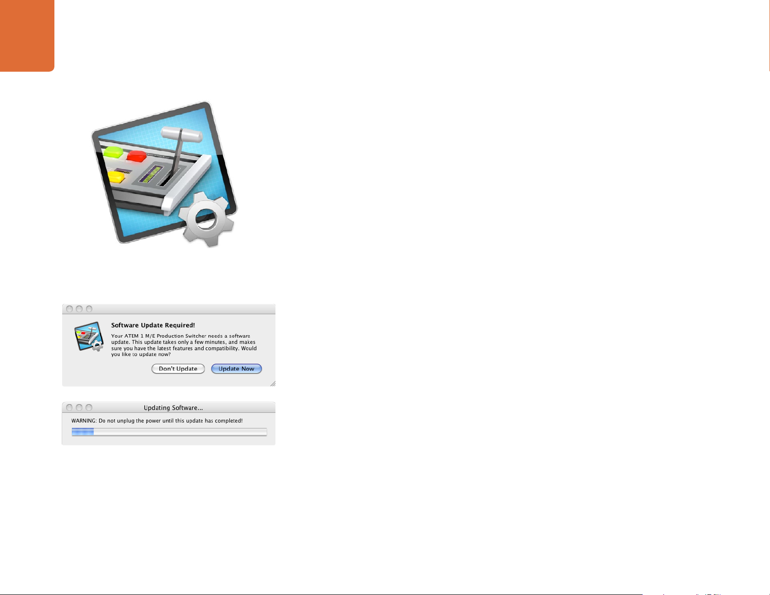
Step 3. If the switcher software requires updating, you will be prompted by a window asking if you would
like to update the software. Select Update Now to initiate the update process. The update process
may take a few minutes. Do not unplug power from the switcher during the software update.
Step 4. Once the software update is complete, a window will prompt you to cycle power on the switcher.
Select OK and cycle power on the switcher.
Page 24
24
Updating the Software
Updating the Broadcast Control Panel Software
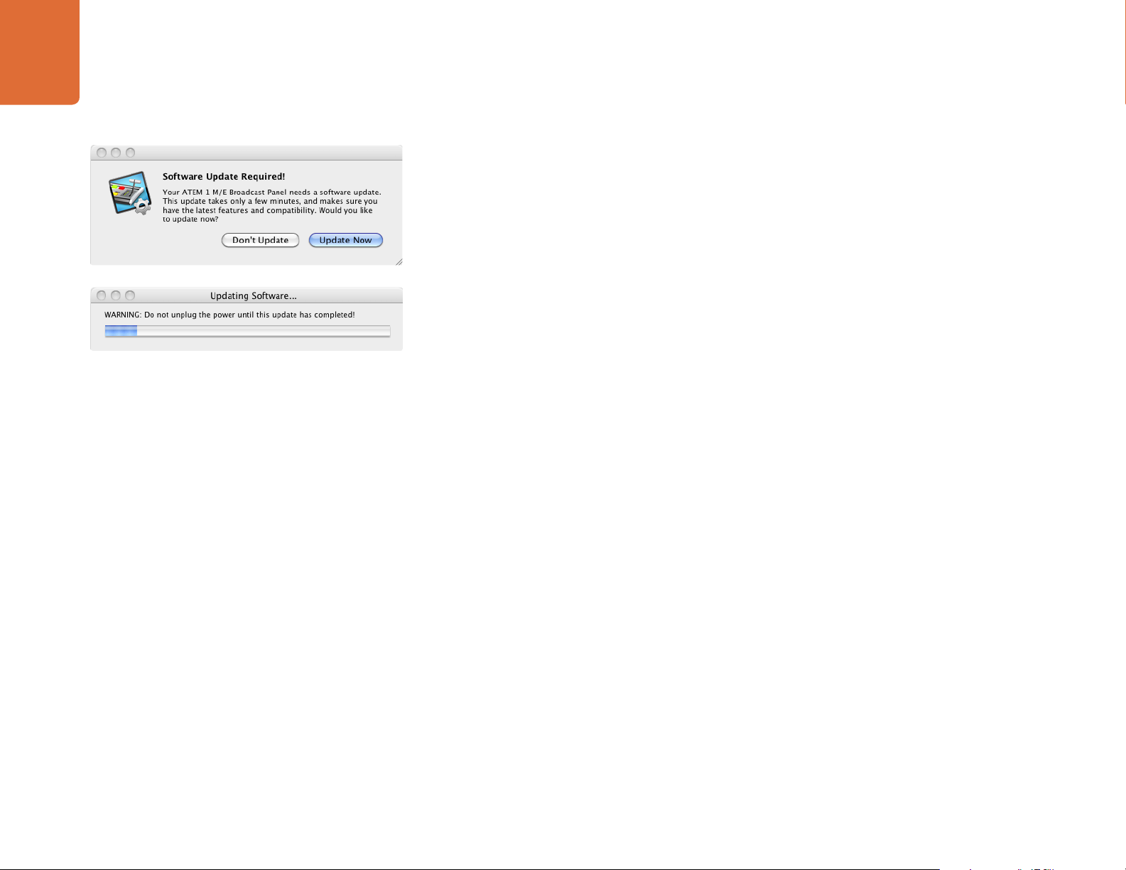
Step 1. Connect the broadcast panel via USB to your computer. The broadcast panel is equipped with
a USB connector which can be connected to a computer's USB 2.0 or USB 3.0 port using a
USB cable.
When upgrading software, make sure the broadcast panel is the only ATEM device connected
via USB to the computer running the setup utility software. If more than one ATEM device is
connected, the panel may not be recognized.
Step 2. Launch the ATEM Setup Utility software.
Step 3. If the broadcast panel software requires updating, you will be prompted by a window asking
if you would like to update the software. Select Update Now to initiate the update process.
The update process may take a few minutes. Do not unplug power from the panel during the
software update.
Step 4. Once the software update is complete, a window will prompt you to cycle power on the broadcast
panel. Select OK and cycle power on the broadcast panel.
Page 25

Connecting Video Outputs
25
Connecting Video Outputs
Production Switcher Outputs
There are multiple video outputs on your ATEM switcher which can be used to connect to a wide range
of video equipment. ATEM Production Studio 4K models include Ultra HD, HD and SD via SDI and HDMI.
ATEM Production Switcher models, excluding ATEM Television Studio, include analog component and
composite video outputs, so you should be able to connect to equipment at any location. Descriptions of
each output connection are listed below.
SDI Program Output
This SDI output switches between Ultra HD, HD and SD. It outputs the main program video output of your
ATEM switcher and can be connected to any SDI based video device. The audio on this output can use
embedded HDMI and SDI audio from your cameras as well as external audio via the switcher chassis' XLR
inputs. ATEM Production Switcher models include a breakout cable for external audio.
HDMI Program Output
Similar to the SDI program output, this output switches between Ultra HD, HD and SD. It outputs the
main program video output of the switcher and can be connected to televisions, video projectors or even
Blackmagic Design's H.264 Encoder or HyperDeck Shuttle. The audio on this output can use embedded
HDMI and SDI audio from your cameras as well as external audio via the switcher chassis' XLR inputs. ATEM
Production Switcher models include a breakout cable for external audio.
Multi View SDI and HDMI Output
This SDI and HDMI output is always high definition and includes 8 video input views, with preview and
program views. Tally is included with red for sources on air, and green for preview. You can connect this
output to televisions and computer monitors with SDI or HDMI connections.
Component Video Program Output
ATEM 1 M/E and 2 M/E Production Switchers feature three BNC component connectors that switch
between SD and HD from the main program output. Component lets you to connect to equipment such as
encoders and video projectors, and provides greater compatibility with older analog equipment.
Standard Definition SDI Program Output
This SDI output always feeds the program video as standard definition on ATEM 1 M/E and 2 M/E production
switchers. It is perfect for connecting to older SD equipment or even generating simultaneous SD and HD
streams. This output can use embedded HDMI and SDI audio from your cameras as well as external audio
via the switcher chassis or breakout cable.
Page 26

26
Connecting Video Outputs
Composite NTSC/PAL Program Output
This output always feeds the program video as standard definition NTSC or PAL composite video on ATEM
1 M/E and 2 M/E Production Switchers. This composite output lets you connect to old video equipment.
Auxiliary SDI Outputs
All ATEM switchers, excluding ATEM Television Studio, have auxiliary SDI connections that output the same
video format in use. Production Studio 4K models are SD/HD/Ultra HD switchable and Production Switcher
models are SD/HD switchable. The number of auxiliary outputs vary between models:
ATEM Production Studio 4K has 1 auxiliary output.
ATEM 1 M/E Production Studio 4K has 3 auxiliary outputs.
ATEM 1 M/E Production Switcher has 3 auxiliary outputs.
ATEM 2 M/E Production Switcher has 6 auxiliary outputs.
Auxiliary outputs can use any internal and external video sources. For example, program feeds if you need
more program outputs, or clean feeds without down stream keying, or even specific video inputs. Aux
outputs are perfect for driving video screens on stage, or feeds where you can independently control what
the viewers see. Aux outputs switch cleanly and can be used as cut only switchers independent of the main
program outputs. The audio on these outputs is embedded SDI program audio.
USB 3.0 Output
The ATEM 1 M/E and ATEM 2 M/E Production Switchers have a USB 3.0 output that can be used to capture
video direct to a Windows PC for real time mastering or waveform monitoring. You can also stream over
the internet using encoding software. Blackmagic Media Express software is included for recording from
this output, as well as Blackmagic UltraScope for waveform monitoring. The USB 3.0 output uses the Aux
1 output so you can customize your output feed. The audio on this output is embedded program audio.
USB 2.0 Output
ATEM Television Studio has a USB 2.0 output which can be used to capture an H.264 compressed master file
of your program. ATEM switchers include Media Express software for recording from this output. The audio
on this output is embedded program audio.
Preview SDI Output
This output shows the source selected on the preview bus on the switcher, as well as preview transitions.
This output is perfect when you want to use a full resolution preview monitor. The audio on this output is
embedded SDI program audio.
Page 27
Using ATEM Software Control
27
Using ATEM Software Control
Interface Overview
The ATEM Software Control is included with your ATEM switcher, and allows you to control your switcher in
a similar way to a full hardware control panel. However instead of menu buttons, it uses a range of pallets
on the right side that shows you all processing features of your production switcher, and allows settings to
be easily made.
You can also use the ATEM Software Control to configure your switcher settings as well as upload graphics
and manage the media pool.
Switcher Control Panel
The software control panel has four tabs: Switcher, Audio, Media and Settings. You can select a tab from the
bottom of the window or by pressing the Shift and left/right arrow hot keys. The media, audio and settings
tabs contain unique settings for the switcher, which can only be made from the software control panel.
When first launched, the switcher screen is selected, which is the main control interface for the switcher.
The software control panel must be connected to a switcher chassis to run.
Mouse or Trackpad Operation
The virtual buttons, sliders and fader bar on the Software Control Panel are operated using your computer
mouse or a trackpad if you’re using a laptop.
To activate a button, click once with the left mouse button. To activate a slider, click and hold down the left
mouse button while dragging. Similarly, to control the fader bar, click and hold down the left mouse button
on the fader bar handle and drag up or down.
Page 28
28
Using ATEM Software Control
Using Keyboard Hot Keys
Hot keys can be used allowing convenient control of some switcher functions using a standard QWERTY
keyboard as shown in the following table:
Hot Keys Function
<1> - <8> Previews source on switcher Inputs 1 - 8
<Shift> <1> - <8> Previews source on switcher Inputs 9 - 16
<Control> <1> - <8> Hot switches source on switcher Inputs 1 - 8 to Program output
Press and release <Control>,
then <1> - <8>
<Control> <Shift> <1> - <8> Hot switches source on switcher Inputs 9 - 16 to Program output
Press and release <Control>,
then <Shift> <1> - <8>
<Control> Turns off hot switching if currently on. The CUT button is lit white.
<Space> CUT
<Return> or <Enter> AUTO
More information on how to use the switcher control panel is included in the next sections.
Hot switches source on switcher Inputs 1 - 8 to Program output.
Hot switching remains on and the CUT button is lit red.
Hot switches source on switcher Inputs 9 - 16 to Program output.
Hot switching remains on and the CUT button is lit red.
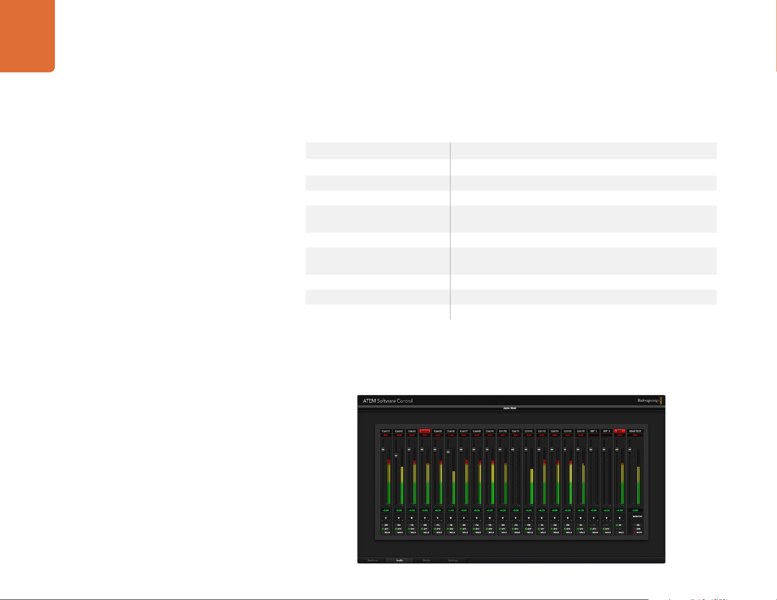
Audio Mixer
The Audio tab in ATEM Software Control contains an audio mixer interface which becomes active when
controlling any ATEM switcher.
Page 29

29
Using ATEM Software Control
ATEM switchers include a built-in audio mixer that lets you use the embedded HDMI and SDI audio from
your cameras, media servers and other inputs without the need for an external audio mixer. This is perfect
when using an ATEM switcher on location or in small spaces within modern OB vehicles as you don't have
to find room for an external audio mixer. The audio is mixed in the Audio tab of ATEM Software Control and
output via the SDI and HDMI program outputs.
On the ATEM Television Studio, the audio mixer also mixes external audio from the AES/EBU input.
ATEM Production Studio 4K models include XLR and RCA inputs for mixing external audio. Mixed audio can
also be output via the XLR outputs and the audio mixer contains independent controls for setting the audio
level and also for selecting solo audio monitoring.
ATEM 1 M/E and 2 M/E Production Switchers include a breakout cable for mixing external audio via XLR
inputs and outputs. The audio mixer contains independent controls for setting the audio level and for
selecting solo audio monitoring.
ATEM 1 M/E, 2 M/E and 1 M/E Production Studio 4K also mixes audio from the switcher's built in media
players.
If you prefer to use an external audio mixer, it's easy to disable the audio for all inputs and you only need to
leave the external audio active in the audio mixer interface.
More information on how to use the audio mixer is included in the next sections.
Media Manager
The media manager allows you to upload graphics and image sequences to the media pool in the ATEM
switcher. Each ATEM switcher model has memory for graphics that’s called the media pool. This memory
varies in size between different ATEM models, and holds images with alpha channel that can be assigned to
a media player for use in the production. ATEM holds 32 still graphics and 2 video clips. ATEM Production
Studio 4K and Television Studio holds 20 still graphics with alpha channel.
So for example you could have the maximum 32 still graphics and 2 clips loaded that will be used on your
live production and then assign each of the 2 media players to various stills as you work. As you take a
graphic off air, you can change the media player graphic to the next graphic you want, and then you can put
that media player back on air with the new graphic.
When a still or clip is loaded into the media pool, the alpha channel is loaded automatically if one is included
in the image. When a still or clip is loaded into a media player, the output of the media player will include
both key and fill outputs. If you select a media player as a key source, for example Media Player 1, both the
fill and the key are automatically selected so you don't have to select them separately. However the key can
still be routed separately so you can use a different key source if you wish.
Page 30
30
Using ATEM Software Control
Switcher Settings
The last tab in the ATEM Software Control allows you to change the video input selections and labels.
Setting labels is important, and they are visible in the Multi View output as on-screen labels and on the
broadcast control panel in the source names row.
In the settings tab, you can also set the switcher video standard. This is the master video standard that the
whole switcher operates at, and it's very important you set this to the same video standard as your video
inputs. More details on setting the video standards are included later in this manual.
The switcher settings also let you customize your Multi View. The arrangement of the Multi View screen
can be changed by clicking on the presets at the bottom right of the M/E 1 Control Panel, or the right side
of the Settings tab on the M/E 2 Control Panel. On all ATEM switchers excluding Television Studio, the
arrangement for the 8 smaller video views are fully routable allowing you to view any source in the switcher.
This lets you monitor cameras, internal sources, media players and even aux outputs on a single monitor.
Multi View saves space when doing portable location based events because you only need a single monitor.
Using the Software Control Panel
The switcher tab is the main control interface for the switcher. During live production, the switcher tab can
be used to select sources and take them to air.
ATEM Mix Effects
You can select the transition style, manage upstream/downstream keyers and turn on/off the master fade to
black. The palettes on the right hand side of the interface are where you adjust transition settings including
transition rates, adjust color generators, control media players, and adjust the upstream and downstream
keyers as well as control fade to black rate.
Mix Effects
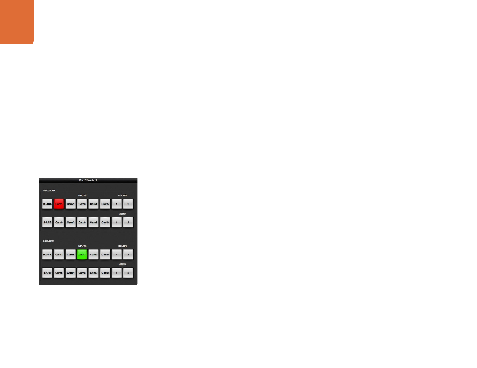
The mix effects block of the switcher tab contains all the source select buttons for the program and preview
buses, allowing external inputs or internal sources to be selected for next transition previewing or switching
to air. On multiple M/E switcher models, this part of the interface controls M/E 1.
Page 31

31
Using ATEM Software Control
Program Bus Source Select Buttons
The program bus source select buttons are used to hot switch background sources to the program output.
The source currently on air is indicated by a button that is illuminated red.
INPUTS Input buttons match the number of external switcher inputs.
BLACK Color black source internally generated by the switcher.
BARS Color bars source internally generated by the switcher.
COLOR 1 and 2 Color sources internally generated by the switcher.
MEDIA 1 and 2 Internal media players that display stills or clips stored in the switcher.
Preview Bus Source Select Buttons
The preview bus source select buttons are used to select a background source on the preview output, this
source is sent to the program bus when the next transition occurs. The currently selected preview source is
indicated by a button that is illuminated green.
ATEM Mix Effects
INPUTS Input buttons match the number of external switcher inputs.
BLACK Color black source internally generated by the switcher.
BARS Color bars source internally generated by the switcher.
COLOR 1 and 2 Color sources internally generated by the switcher.
MEDIA 1 and 2 Internal media players that display stills or clips stored in the switcher.
Transition Control
Transition Control and Upstream Keyers
CUT
The CUT button performs an immediate transition of the program and preview outputs, overriding the
selected transition style.
AUTO/RATE
The AUTO button will perform the selected transition at the rate specified in the RATE display. The
transition rate for each transition style is set in the transition palette for that style and is displayed in
the RATE window of the transition control block when the corresponding TRANSITION STYLE button
is selected.
The AUTO button illuminates red for the duration of the transition and the RATE display updates to indicate
the number of frames remaining as the transition progresses. If an ATEM broadcast panel is connected, the
fader bar indicator on the panel updates to provide visual feedback on the progress of the transition.
Page 32

32
Using ATEM Software Control
Fader Bar
The fader bar is used as an alternative to the AUTO button and allows the operator to manually control
the transition with a mouse. The AUTO button illuminates red for the duration of the transition and the
RATE display updates to indicate the number of frames remaining as the transition progresses. If an ATEM
broadcast panel is connected, the fader bar Indicator on the panel updates to provide visual feedback on
the progress of the transition.
Transition Style
The TRANSITION STYLE buttons allow the operator to select one of five types of transitions; mix, dip, wipe,
DVE, and stinger. The available transitions depend on your switcher model. For example the Television
Studio does not have DVE and stinger transitions. The selected transition style is indicated by a yellow
illuminated button.
PREV TRANS
The PREV TRANS button enables the preview transition mode, allowing the operator to verify a mix, dip,
Transition Control
wipe or DVE transition by performing it on the preview output using the fader bar. When the PREV TRANS
is selected you will see the preview output match the program output, and then it's simple to practice your
selected transition with the fader bar to confirm you are going to get what you want. This is a very helpful
feature to avoid mistakes on air!
Next Transition
The BKGD, KEY 1, KEY 2, KEY 3, KEY 4 buttons are used to select the elements which will transition on air or
off air with the next transition. The number of available keyers depends on your switcher model. All keys can
be faded on and off when the main transition occurs, or you can select just keys to transition individually, so
the main transition control can be used to fade keys on and off.
When selecting the elements of the next transition, the switcher operator should look at the preview video
output because it provides an accurate representation of what the program output will look like after the
transition is completed. When only the BKGD button is selected, a transition from the current source on the
program bus to the source selected on the preview bus will occur without any keyers. You can also select
only keyers to transition, leaving the current background live throughout the transition.
ON AIR
The ON AIR indicator buttons indicate which of the keys are currently on air and can also be used to
immediately cut a key on or off air.
Page 33

33
Using ATEM Software Control
Downstream Keyers
TIE
The TIE button will enable the DSK on the preview output, along with the next transition effects, and tie it to
the main transition control so that the DSK can be taken to air with the next transition.
The DSK will transition at the rate specified in the RATE display of the transition control block. If the DSK is
tied, the signal routing to the clean feed 1 is unaffected.
ON AIR
The ON AIR button is used to cut the DSK on or off air and indicates whether the DSK is currently on or off
air. The button is illuminated if the DSK is currently on air.
AUTO
The AUTO button will mix the DSK on or off air at the rate specified in the DSK RATE window. This is similar
to the main AUTO rate on the transition control block, however it's limited only to the specific downstream
Downstream Key
Fade to Black
keyer. This can be used to fade up and down bugs and logos, such as live or replay bugs during production,
without interfering with the main program production transitions.
Fade to Black (FTB)
The FTB button will fade the whole program video output to black at the rate specified in the fade to black
RATE window. Once the program output has been faded to black, the FTB button will flash red until it is
pressed again. Doing so will fade up from black at the same rate, or you can enter a new rate in the Fade
to Black palette in the Switcher tab. Fade to black is mostly used at the start of your production, and at the
end of your production, or when cutting to commercial breaks. It ensures all layers in the switcher are faded
down together. A fade to black cannot be previewed.
Processing Palettes
Processing Palettes
The following processing palettes are available in the software control panel for the ATEM 1 M/E Production
Switcher model. These change based on the model you’re connected to, and are an easy way to see what
processing is available in the switcher. Different ATEM models will have different features, so the palettes
can change. The palettes also show the order of the processing in the switcher.
You can expand and minimize palettes to save space and scroll them up and down to get the adjustments
you need to set.
Color Generator 1 and 2
The ATEM switcher has two color matte generators which can be configured from the color generator
palette using a color picker or by setting hue, saturation, and luminance levels.
Page 34

34
Using ATEM Software Control
Media Player 1 and 2
The ATEM switcher has two media players which playback the clips and stills that are stored in the media
pool memory built into the switcher. The drop down list is used to select the still or clip that will be played or
made available on the media player input to the switcher. When a clip is selected, the transport controls can
be used to play, pause and loop the clip. Controls are also provided to step forward and backward through
frames of the clip.
Upstream Key 1 to 4
Depending on the switcher model, ATEM has up to four upstream keyers per M/E which can be configured
from the upstream key palettes. Each keyer has its own palette. Within each palette the keyer can be
configured as a luma key, chroma key, pattern key or DVE. The type of key available will also depend on
the switcher model and if the DVE is available. The selected palette will display all the parameters that
Processing Palettes
are available to configure the keyer. More information on how to use upstream keyers is included later in
this manual.
Because the ATEM 1 M/E Production Switcher, 1 M/E Production Studio 4K and Television Studio models
have only 1 M/E, these keyers are all labeled as being for M/E 1. On the ATEM 2 M/E Production Switcher
model, the labels will show which M/E these keys are connected to.
Transition
The transition palette is where you can configure the parameters of each transition style. For example for the
dip transition the palette has a drop down where you can select the dip source and for the wipe transition
the palette displays all the available wipe patterns. There are lots of variations of transitions, and a large
number of transitions can be created by combining settings and features in the transition palette.
It's worth noting that simply selecting a specific style of transition in this palette will only adjust the settings
for these transitions, and you still need to select the style of transition you want to perform in the transition
control section on the software or hardware control panel. For ease of use, some people like to use the
hardware based broadcast panel for switching, while using the software panel palettes for setting up the
transition. The software and hardware panels work together and mirror all settings, so you can use any
combination you like!
Downstream Key 1 and 2
The ATEM has two downstream keyers which can be configured from the downstream keys palette.
The palette has drop down boxes for selecting the fill and key signals to the keyer, sliders to set the clip and
gain values, pre-multiplied, and mask settings.
Fade to Black
The Fade to Black palette is where you can set the fade to black transition rate.
Page 35

35
Using ATEM Software Control
Capture Palette
The Capture palette in ATEM Software Control provides an incredibly easy way to capture video from the
USB port of ATEM switchers without having to use any other video software and without having to use
additional capture hardware. The video standard for capture is automatically set to the same as the switcher
video standard so you don't even have to set it. All you have to do is press the red record button to capture
and press it again to stop!
The capture palette is great for quick captures but if you want more features, such as organizing your video
in bins and a playback window, please refer to the Media Express section documented later in this manual.
How to Capture
Start by expanding the Capture palette and you will see an unlocked icon which means the palette can be
expanded or collapsed. You'll probably want to keep the capture palette visible while capturing so click the
icon to lock the palette in the expanded position.
When you want to capture, select the Enable Capture checkbox. You might wish to leave this box unchecked
if you find the timecode and audio meters to be distracting when you are not capturing video.
If you want to capture uncompressed video and audio from the USB 3.0 port of an ATEM 2 M/E or 1 M/E
Production Switcher, you'll need a compatible Windows computer with USB 3.0. Whatever video and audio
The Capture Palette appears below the Processing Palettes
is output on Aux 1 can also be captured from the USB 3.0 port. The Capture Setup button contains capture
settings for your ATEM Production Switcher including which model of ATEM switcher you are capturing
from, the choice of uncompressed or compressed codecs and the location for the captured files. You can
read more information about using USB 3.0 for video capture in the "Working with USB 3.0" section later
in this manual.
You can capture H.264 video with audio from the USB 2.0 port of an ATEM Television Studio using a Mac OS
X or Windows computer. Whatever video and audio is output on the Program output can also be captured
from the USB 2.0 port. The Capture Setup button contains capture settings including the resolution and
quality of H.264 files for ATEM Television Studio and the location for the captured files.
Page 36

36
Using ATEM Software Control
Using the Audio Mixer
The audio tab is used to mix audio sources connected to any ATEM switcher via HDMI, SDI, external audio
and also from the built-in media players in ATEM 1 M/E and 2 M/E Production Switcher models.
Cameras, media players and external audio sources are listed along the top of the audio mixer along with
the master audio output for the program outputs of the switcher.
Below each audio source is an audio level meter, a fader for setting the maximum audio level, and a
crossfader for setting the left/right audio channel balance. The master fader on the right side of the audio
mixer is used to set the gain on the audio level on the SDI and HDMI program outputs and has its own
audio level meter. On all ATEM switcher models except for the ATEM Television Studio, the monitor fader
and checkboxes appear below the master fader and set independent audio levels and also allow solo
monitoring on the audio outputs.
The checkboxes below each audio level meter determine whether audio is always available for mixing
or only when the source is on air. On ATEM Switchers, excluding Television Studio, the solo checkbox
determines whether the audio source should be used for solo audio monitoring via the switcher chassis or
audio breakout cable. If you notice the solo and monitor settings are grayed out, you either have an ATEM
Television Studio or program audio is selected for the audio breakout setting in the settings tab.
Tally
Any source whose audio is on air is lit with a red tally light in the software. External audio is on air by default
so the EXT tally light is usually lit red. In the example on this page, Cam4 and Cam7 are lit because their
The audio mixer displays red tally lights for any audio sources
that are currently on air, as well as audio level, audio balance and
checkboxes for selecting which audio should be used.
audio is set to be always on.
Audio Level
Drag the audio level fader to set the gain on the audio level for each camera and audio source. The green
number under each audio level meter shows the maximum audio level set by the fader.
If you are operating an ATEM switcher, excluding Television
Studio, and notice the solo and monitor settings are grayed out,
you have program audio selected for the audio out setting in the
settings tab. The solo and monitor settings are always grayed out
on ATEM Television Studio.
The number above the audio meter shows the peak audio level reached by the audio source. A green
number represents low to medium audio levels. If the audio meter is regularly showing red, and the red
number above it is not changing, then you should reduce the audio level to avoid audio distortion. After
adjusting the audio level, you may wish to reset the red number by clicking on it once. Observe the new
number to make sure it changes for a while and does not immediately shoot up and become stuck on a red
number. If it does, you may need to reduce the audio level even further.
Audio Balance
The audio mixer supports stereo audio from each audio source. If you wish to change the left/right audio
channel balance for a camera or other audio source, slide the crossfader to the desired balance point.
Page 37

37
Using ATEM Software Control
Audio Source Selection
Below each audio level meter, you will find the ON and AFV checkboxes that select which audio sources are
sent to the program output of the switcher.
ON Selecting the direct mix to ON allows an audio input to be permanently mixed into the program
AFV Audio-follow-video (AFV) allows audio to crossfade when inputs change. The audio will only be
SOLO All ATEM switchers excluding ATEM Television Studio can use the XLR audio output via the
Master Audio Level Output
The master fader on the right side of the audio mixer is used to set the gain on the audio level on the SDI
and HDMI program outputs and has its own audio level meter.
Audio Mixer Monitor
On all ATEM switchers excluding ATEM Television Studio the monitor fader and checkboxes appear below
The audio meter for Cam1 is shown in gray to indicate that its
audio will not be used as neither of its ON or AFV checkboxes are
enabled. Cam2 has AFV selected but its audio is not currently
being used as the camera is not on air as is indicated by its unlit
tally light. Cam4 and Cam7 have their direct mix set to ON so
their mixed audio is always used, and their tally lights remain lit,
even if another camera is currently on air. The audio level meters
for Cam3, Cam5, Cam6 and Cam8 show that no audio is present
on these cameras.
the master fader and control the audio output behavior. You can use these settings to set independent
audio levels for monitoring the audio mix without affecting the program output audio. If you've selected
a solo input that you want to monitor, these settings let you control the audio monitor levels for the single
input without affecting the program output audio. You can enable these settings by going to the settings
tab and selecting the audio out setting to "monitor audio".
ON Select ON to enable audio monitoring on the audio breakout cable output.
DIM Select DIM to temporarily reduce the monitor audio level without having to adjust the fader.
MUTE Select MUTE to disable all audio on the audio breakout cable output.
output, even when the associated video source is not on air. The red tally light will always be lit
because the audio is always on air. Selecting this option automatically disables AFV.
sent to the program output when the input is on air, lighting the red tally light above. Selecting
this option automatically disables the direct mix ON setting.
chassis or breakout cable as a dedicated monitor output. Selecting solo exclusively outputs
that single audio source to the monitor output so you can listen clearly to any single input when
required. This is an important feature which lets you confirm audio content before putting it to
air and without affecting the program output audio. When solo is deselected the audio output
will return to its original state.
Select ON to return to your preferred listening level.
The monitor fader and checkboxes set independent audio levels
and allow solo monitoring on the audio output.
Using the Media Manager and Media Pool
The media tab is used to transfer stills and clips from your computer into the switcher's Media Pool. On the
left is a browse screen that you can use to navigate to the location of still image and image sequence files
on your computer. On the right, the Media Pool shows what is currently loaded into the switcher's memory.
Page 38

38
Using ATEM Software Control
Navigating the Browse Window
The browse window is a simplified file browser that lets you navigate your computer to look for graphics
files. The drop down list at the top shows the current folder. You can use the drop down to navigate back
one level or multiple levels at once.
The rest of the browse window shows you a list of the files and folders that are in the selected folder. You can
double click on a folder to enter the folder and view its contents. When you enter a folder the drop down
list is updated with the name of the current folder. When possible, the file list will show the resolution of any
graphics files in the list so you can check the correct television resolution graphics before loading them.
Browsing and Loading Files
The ATEM 1 M/E, 1 M/E Production Studio 4K and 2 M/E Production Switcher media pools have 32 still
image windows. They also have 2 clip windows that have a location for audio. On the ATEM Television
Studio and ATEM Production Studio 4K only the first 20 still image windows in the media pool are active.
To copy a still, simply drag it from the browse screen and drop it into an empty window in the Media Pool.
To copy a clip you must select a sequence of TGA images in the browse window and drag the entire targa
sequence and drop it into the clip window. You can do this by selecting the first file, then scrolling to the
Browse Window
last file in the image sequence, and while holding the shift key, selecting the last file. All the files will then
highlight and then can be all dragged into any of the two clip windows in the media pool. Audio files, which
are used when playing a clip in a stinger transition, can be dragged and dropped into the audio portion of
the clip window labeled Drag Audio Here.
ATEM Media Pool
When copying, a progress bar will show the status of the transfer. You can drop multiple files into the media
pool, even if the first images have not completed copying, as they will be scheduled to download one after
the other. If a clip or still is dragged and dropped into a window which already has content loaded, the
existing content will be overwritten.
Compatible Files - The ATEM media pool supports PNG, TGA, BMP, GIF, JPEG and TIFF still image formats.
Clips are simply a sequence of images. Audio files must be WAV, MP3 or AIFF.
ATEM Media Pool
After the still and clip files have been transferred into the switcher's memory, the still window will show
a thumbnail of the image and for clips, the window will show a middle frame from loaded clip. Stills are
marked with a number indicating their position in the media pool so you can identify them on the broadcast
panel when assigning an image to the media player. Clips have a status bar that indicates the number of
frames in the clip.
Page 39

39
Using ATEM Software Control
If you want to keep track of the file name for each still or clip, then as you hover the mouse over the
thumbnails, you will see the file name display at the bottom of the window. This is very useful, as in the
media player palette in the switcher tab, as well as the Photoshop plug-in, you will see a list of media pool
still and clip numbers as well as the file name.
There are two numbers displayed against the clips or stills in the media pool, and these indicate the current
still or clip selected to the media players. Media player 1 is shown with a 1, and media player 2 is shown with
a number 2. When a media player clip or still is on the program output, the corner badge is red. When a
media player clip or still is on the preview output, the corner badge is green.
You can change the media player assignment from the media tab by using the copy to media buttons. First
select the clip or still you want to copy to one of the media players. The selected item will have a yellow
border. Press the copy to media 1 or the copy to media 2 buttons at the bottom of the window to copy the
selected still or clip to one of the media players. The badge will update to reflect the current still or clip that
is being used by the media player.
You can also assign media players to stills or clips from the switcher tab media player palette, from
the hardware based ATEM broadcast panels, or in some cases from the Photoshop plug-in when
downloading stills.
Changing Switcher Settings
The settings tab is used to change video inputs and labels, set the switcher video standard, adjust the
downconverter aspect ratio, adjust media players and to customize the Multi View.
Set Video Inputs and Labels
Setting Video Inputs
The video input settings are used to select the inputs and change labels. On some models of ATEM switcher,
the video inputs can select between different video sources, such as HDMI or SDI, or HDMI and component
video connections. You can identify switchable connections on the rear processor chassis because all inputs
are numbered, and any inputs that can switch with have the same input number on their label.
For example, ATEM 1 M/E Production Studio 4K shares the Input 1 setting between an HDMI and SDI
connector, which are both labelled Input 1 on the back panel. In the Input Settings window, click Input 1 to
select between HDMI and SDI.
Inputs can have customized labels and these labels appear on ATEM broadcast control panels and on the
Multi View. Long and short labels need to be entered, as long labels are often too long to be displayed on
broadcast control panel’s smaller displays.
A short 4 character name is used to identify the video input on the source names display of the broadcast
panel. The longer input names support up to 20 characters and are displayed in various drop down source
selection boxes on the software control panel and also on the Multi View windows on-screen labels.
Page 40

40
Using ATEM Software Control
To change an input name, click in the text field, enter the text and select set. The input name will be updated
on the Multi View, software control panel and broadcast panel if one is connected. It's a very good idea to
change both the short and long labels at the same time, so they match. For example Camera 1 would be
entered in as a long label, and CAM1 as the short label.
Setting the Switcher Video Standard
The video setting is used to select the operating video standard of the ATEM switcher, and this must
be set to the same video standard as the video sources you are plugging into the ATEM switcher. If they
don't match, the inputs won't appear correctly, and will most likely remain black. A good way to work out
the video standard you should use is to check your cameras, and then set the switcher video standard to
the same format.
Set Video Standard
ATEM currently supports the following video standards:
ATEM Production Studio 4K Models ATEM Television Studio, 2 M/E Production
SD 525 59.94i NTSC SD 525 59.94i NTSC
SD 625 50i PAL SD 625 50i PAL
SD widescreen anamorphic 525 59.94i 16:9 SD widescreen anamorphic 525 59.94i 16:9
SD widescreen anamorphic 625 50i 16:9 SD widescreen anamorphic 625 50i 16:9
HD 720 50p HD 720 50p
HD 720 59.94p HD 720 59.94p
HD 1080 50i HD 1080 50i
HD 1080 59.94i HD 1080 59.94i
HD 1080 23.98p
HD 1080 24p
HD 1080 25p
HD 1080 29.97p
HD 1080 50p
HD 1080 59.94p
Ultra HD 23.98p
Ultra HD 24p
Ultra HD 25p
Ultra HD 29.97p
Switcher and 1 M/E Production Switcher
Page 41

41
Using ATEM Software Control
To set the video standard, select the video standard from the menu, and then select the set button. Any time
the video standard is changed, it will erase any frames you have loaded into the media pool.
Setting the Audio Output Behavior
The audio out setting is available for ATEM 1 M/E, 2 M/E and Production Studio 4K models. This setting lets
you select whether the XLR audio connectors output program audio or monitor audio.
Program audio is the same audio that the audio mixer sends to the SDI and HDMI program outputs. Monitor
settings and solo monitoring are disabled in the audio mixer when program audio is selected.
Set the audio output behavior
Monitor audio allows you to listen to the program audio mix of all inputs, or just a solo input, at your
preferred volume level and without affecting the audio on the program output. These monitor settings are
only available to the audio mixer when monitor audio is selected for the audio out setting in the settings tab.
When you use monitor audio to listen to a solo audio source, all other audio output is muted on the audio
output. Selecting solo in the audio mixer does not affect the program output audio. You can monitor the
solo audio source regardless of whether or not it is on air.
ATEM Television Studio does not have an independent audio output for monitoring and is always set to
program audio. The program output connections provide SDI and HDMI embedded audio for monitoring.
Page 42

42
Using ATEM Software Control
Setting the Down Converter Outputs
When running ATEM Production Studio 4K models in Ultra HD 4K, the HD-SDI program output always
outputs down converted high definition 1080i video for connection to HD-SDI equipment. High definition
or standard definition video inputs are always output as HD or SD video respectively.
ATEM Television Studio does not have any down converted outputs.
When running the ATEM 1 M/E and 2 M/E production switchers in high definition, the HD signal is
permanently down converted to SD via SDI and composite video outputs for connection to older devices.
720 50p and 1080 50i down converts to 625 50i PAL. 720 59.94p and 1080 59.94i down converts to 525 59.94i
Setting the Down Converter Style
NTSC.
Down conversion provides the following aspect ratios:
Center Cut Crop left and right side making a 4:3 image.
Letterbox Scales the video down with black bars to top and bottom.
Anamorphic Horizontal scale (squeeze) to make 16:9 image fit 4:3. Requires an anamorphic or
Setting the Serial Control Output
This option will allow camera and server control from the ATEM 1 M/E and 2 M/E Production Switcher. This
is not currently supported in the current ATEM software and will be added in a future software update.
16:9 monitor or television to correct the aspect ratio.
Setting the Media Pool Clip Length
Adjusting the Media Pool Clip Length
On ATEM 1 M/E and 2 M/E models, the Media Pool features two clips that share the same pool of memory.
By default, each clip receives half of the available memory which determines the maximum number of
frames. If you need a clip to be longer, adjust the balance of frames. It's worth remembering that lengthening
one clip will shorten the other.
Clip Length Table
ATEM Switcher Video Format Clip Length
ATEM 1 M/E and 2 M/E
Production Switcher
ATEM 1 M/E Production Studio 4KUltra HD 4K 180 frames
1080i 180 frames
720p 360 frames
SD 900 frames
1080i, 1080p 720 frames
720p 1600 frames
SD 3600 frames
Page 43

43
Using ATEM Software Control
Customizing the Multi View
The Multi View settings allow you to set the Multi View orientation. On the ATEM Production Studio 4K,
1 M/E and 2 M/E Production Switchers the larger program and preview windows have fixed routing, while
the 8 smaller windows are fully routable so you can monitor any switcher source. By default, external Inputs
1 - 8 are routed to Multi View source windows 1 to 8. Simply click the menus to select what sources are
viewed on each window! On the ATEM Television Studio the Multi View sources are fixed to show you
Program, Preview, the 6 inputs and the 2 media players.
The Multi View also includes a tally feature, so if any of the sources in the Multi View are used in a layer on
the program or preview outputs, they will be highlighted red or green. A white border means your source is
not currently on-air on the program or preview outputs. A red border to indicates the source is used on the
program output and a green border indicates a source is selected on the preview output.
The preview window on the Multi View output features safe area markers so you can make sure your program
Customize the Multi View
Auxiliary Outputs Control Menus on Mac OS X
will look great on any monitor. In HD, the outer border represents the 16:9 graphics safe area and the inner
border represents the 4:3 graphics safe area. In SD, the single border represents the action safe area. You
can also change the orientation of the Multi View windows by selecting one of four different layouts using
the icons at the bottom of the Multi View settings window. The Multi View output is always HD even when
running in standard definition so you can see all your sources in higher resolution.
Controlling Auxiliary Outputs
Auxiliary outputs are separate SDI outputs on the switcher that can have various inputs and internal sources
routed to them. They are very similar to router outputs, and all video inputs, color generators, media players,
program, preview and even color bars can be output. ATEM 2 M/E Production Switcher has 6 auxiliary
outputs , ATEM 1 M/E have 3 auxiliary outputs, and ATEM Production Studio 4K has 1 auxiliary output.
Auxiliary Outputs Control Menus on Windows
Routing Auxiliary Outputs
Each aux output has a menu for selecting the source to output on the aux video output. Simply select the
menu, then scroll the list for the source you want to output. When selected, the output on the selected aux
will change immediately. You can see the current source with a tick in the menu item.
There is a range of sources available, including black, all video inputs, color bars, media players fill and
media player key outputs, program, preview and clean feeds.
More information about Auxiliary outputs and how to use them is explained in the Using Auxiliary Outputs
section. Aux outputs are extremely powerful and allow many exciting possibilities like alternative switcher
outputs, or they are very commonly used for driving video projectors and video walls on stage during
concerts and live performances. Most modern live performances have complex multi media aspects to
them, and the aux outputs are designed to allow you to control all these displays from your ATEM!
Page 44

44
Using ATEM Software Control
Button Mapping
ATEM software and hardware control panels support button mapping so you can assign your most
important sources, especially cameras, to the most accessible buttons in the program and preview rows.
Occasional sources can be assigned to less prominent buttons. Button mapping is set independently for
each control panel so button mapping set on a software control panel will not affect the button mapping
set on a hardware control panel.
For software control button mapping you'll find the button mapping options in the preferences window of
ATEM Software Control.
Transition Control
When you first receive your ATEM switcher, it will be set to Program/Preview switching which is the current
standard for an M/E switcher. You can change this preference to A/B Direct if you wish to use older style A/B
switching. You'll find the Transition Control options in the Preferences window of ATEM Software Control.
Saving and Restoring Switcher Settings
ATEM Software Control lets you save and restore either specific settings, or all of the switcher settings you
have created. This powerful feature is incredibly time saving on live productions where regular settings are
used. For example, you can immediately restore saved lower third graphics and detailed key setups from a
laptop or USB drive.
Button mapping and Transition Control
Saving settings menu
Saving your Settings
Step 1. Go to the menu bar in ATEM Software Control and select File>Save As.
Step 2. A window will open asking for a file name and destination folder. After you have made your selection,
click Save.
Step 3. You'll now see the Save Switcher State panel containing checkboxes for all the available settings on
each block of your ATEM switcher. The Select All checkbox is enabled by default. If you save with Select All
enabled, ATEM Software Control saves your entire switcher settings. If you want to choose specific settings
to save, you can deselect settings individually, or to remove all settings click Select All once to deselect
them. Now you can select specific settings you want to save.
Step 4. Click Save.
Page 45

45
Using ATEM Software Control
ATEM Software Control saves your settings as an XML file together with a folder for ATEM Media Pool
contents.
After you have saved your settings you can quick save at any time by selecting File>Save, or by pressing
Command S for Mac, or Ctrl S for Windows. Doing so will not overwrite your previous save, but will add a
new XML file to your destination folder which is clearly identified with a time and date stamp. This means
you can always restore a previous save if necessary.
Restoring your Settings
Step 1. Go to the menu bar in ATEM Software Control and select File>Restore.
Step 2. A window will ask for the file you want to open. Select your save file and click Open.
Step 3. You'll now see a window containing active checkboxes for your saved settings on each block of your
ATEM switcher. Leave Select All enabled to restore all your saved settings, or select only the checkboxes for
the settings you want to restore.
Step 4. Click Restore.
If your switcher settings are saved on a laptop, it’s easy to take all your settings with you on location. Connect
your laptop to any ATEM switcher and quickly restore your switcher settings.
With ATEM Software Control you can save and restore all your
switcher settings for your live production, including key settings,
transition styles, media pool contents and more.
Saving your switcher settings on a laptop gives you the portability
to restore your settings on any ATEM switcher. Saving to a USB
drive means you can even carry your settings in your pocket.
Live production can be a busy and exciting time and you're always working in the moment, which means
you can easily forget to back up your saved files when the production is over. If you have settings you want
to keep, save them to your computer and an external drive, such as a USB drive. This means you can carry
your settings with you and have a back up in case your settings are accidentally deleted on your computer.
Saving your Startup State
If you have your switcher set up the way you want it, you can easily save your entire switcher state as your
default startup state. Go to the File menu in ATEM Software Control and select Save Startup State. Now
whenever you restart your switcher, it will start up with your saved settings by default. If you want to clear the
startup state and revert to the factory settings on restart, go to the File menu and select Clear Startup State.
Page 46

CUT
SHIFT
ON
KEY 1
KEY1KEY2KEY3KEY
4
PATTRN
KEY
CHROMA
KEY
LUMA
KEY
MASK
MENU
HOME
DVE
BKGD
KEY 2 KEY 3 KEY 4
ON ON ON
1 2 3
4 5 6
7 8 9
CAM 0 CLR
FILL
DIP
MIX
DSK 1
TIE
DSK 2
Control Panel
Switcher
Main
Backup
Main
Backup
TIE
DSK 1
CUT
DSK 2
CUT
Using the ATEM 1 M/E Broadcast Panel
46
Using the ATEM 1 M/E Broadcast Panel
Control Panel Overview
The ATEM 1 M/E Broadcast Panel plugs in using an ethernet connection to the ATEM processor chassis.
This keyboard has similar functions to the software panel, and the main buttons are laid out in a similar M/E
style, so it's easy to move between the hardware and software interfaces.
If fast and critical live switching is being done, then the ATEM Broadcast Panel is an incredibly fast and
robust control solution. There's nothing like pushing high quality buttons on a panel to ensure fast and
accurate switching!
When using the hardware broadcast panel and software panels together, any change on one panel will be
reflected on the other, and you can use both panels at the same time. You can also plug in more than one
ATEM 1 M/E Broadcast Panel
KEY1KEY2KEY3KEY
LUMA
CHROMA
KEY
KEY
MASK
MENU
4
PATTRN
DVE
KEY
HOME
1 2 3
4 5 6
7 8 9
CAM 0 CLR
Control Panel
Main
ON ON ON
ON
CUT
BKGD
KEY 1
FILL
DIP
MIX
SHIFT
PREV
CUT AUTO
TRANS
KEY 2 KEY 3 KEY 4
Backup
Switcher
Main
DSK 1
DSK 2
TIE
TIE
Backup
DSK 1
DSK 2
CUT
CUT
DSK 1
DSK 2
FTB
AUTO
AUTO
broadcast panel.
Using the Control Panel
Mix Effects
The program bus, preview bus and source names display are used together to switch sources on the
program and preview outputs.
Source Names Display
The source names display uses a 4 character label to represent the switcher's external inputs or internal
sources. Labels for the 8 external inputs can be edited on the settings tab of the software control panel.
Labels for the internal sources are fixed and don't need to be changed.
ATEM Mix Effects
Pressing the SHIFT button will change the source names display to show extra sources, called shifted
sources, allowing selection of up to 20 different sources.
When aux has been selected in the system control block, pressing the SHIFT and CUT/FILL buttons
simultaneously will change the source names display to show protected sources, available for routing to
auxiliary outputs. Protected sources are program, preview, clean feed 1 and clean feed 2.
Program Bus
The program bus is used to hot switch background sources to the program output. The source currently on
air is indicated by a button that is illuminated red. A blinking red button indicates that the shifted source is
on air. Pressing the SHIFT button will display the shifted source.
Page 47

47
CUT
SHIFT
ON
KEY 1
KEY1KEY2KEY3KEY
4
PATTRN
KEY
CHROMA
KEY
LUMA
KEY
MASK
MENU
HOME
DVE
BKGD
CUT AUTO
KEY 2 KEY 3 KEY 4
ON ON ON
1 2 3
4 5 6
7 8 9
CAM 0 CLR
PREV
TRANS
FILL
DIP
MIX
DSK 1
TIE
DSK 2
Control Panel
Switcher
Main
Backup
Main
Backup
TIE
DSK 1
CUT
DSK 2
CUT
DSK 1
AUTO
DSK 2
AUTO
FTB
Using the ATEM 1 M/E Broadcast Panel
KEY1KEY2KEY3KEY
4
LUMA
CHROMA
PATTRN
DVE
KEY
KEY
KEY
MASK
MENU
HOME
CUT
FILL
SHIFT
PREV
TRANS
ATEM Mix Effects
1 2 3
4 5 6
7 8 9
CAM 0 CLR
Control Panel
Main
ON ON ON
ON
BKGD
KEY 1
DIP
MIX
CUT AUTO
KEY 2 KEY 3 KEY 4
Backup
Switcher
Main
DSK 1
DSK 2
TIE
TIE
Backup
DSK 1
DSK 2
CUT
CUT
DSK 1
DSK 2
FTB
AUTO
AUTO
Preview Bus
The preview bus is used to select a source on the preview output. This source is sent to program when the
next transition occurs. The selected source is indicated by a button that is illuminated green. A blinking
green button indicates that the shifted source is on preview. Pressing the SHIFT button will display the
shifted source.
SHIFT
The SHIFT button provides a global shift and is used to shift the program, preview, and select busses along
with the label. It also provides a shift for the transition type and joystick and other menu functions.
Double-pressing buttons in the preview and select busses, as well as the transition type buttons, is the same
as shift-selecting them and can be a faster way to shift-select buttons. Double-pressing is not implemented
for the program bus as it would cause the program output to momentarily show the wrong source.
Destination Display and Select Bus
The destination display works in conjunction with the source names display and select bus and is used to
assign sources to auxiliary outputs and keyers.
The 8 character destination display and select bus together show you the routing of sources to keys and
auxiliary outputs. The currently selected source is indicated by an illuminated button. A blinking button
indicates a shifted source. A green illuminated button identifies a protected source. Protected sources are
program, preview, clean feed 1 and clean feed 2.
CUT/FILL
When a key setup menu is selected and the CUT/FILL button is pressed, the destination display and select
bus change to show the currently selected cut signal (also known as the Key signal) for that key. When
selecting sources for auxiliary outputs, pressing the CUT/FILL button along with the SHIFT button displays
program, preview, clean feed 1 and clean feed 2 as sources for selection on the select bus.
Page 48

48
ON
KEY 1
BKGD
CUT AUTO
KEY 2 KEY 3 KEY 4
ON ON ON
1 2 3
4 5 6
7 8 9
CAM 0 CLR
DIP
MIX
DSK 1
TIE
DSK 2
Control Panel
Switcher
Main
Backup
Main
Backup
TIE
DSK 1
CUT
DSK 2
CUT
DSK 1
AUTO
DSK 2
AUTO
FTB
Using the ATEM 1 M/E Broadcast Panel
KEY1KEY2KEY3KEY
LUMA
CHROMA
KEY
KEY
MASK
MENU
4
PATTRN
DVE
KEY
HOME
1 2 3
4 5 6
7 8 9
CAM 0 CLR
Control Panel
Main
ON ON ON
ON
CUT
BKGD
KEY 1
FILL
DIP
MIX
SHIFT
PREV
CUT AUTO
TRANS
KEY 2 KEY 3 KEY 4
Backup
Switcher
Main
DSK 1
DSK 2
TIE
TIE
Backup
DSK 1
DSK 2
CUT
CUT
DSK 1
DSK 2
FTB
AUTO
AUTO
Transition Control and Upstream Keyers
Transition Control and Upstream Keyers
CUT
The CUT button performs an immediate transition of the Program and Preview outputs, regardless of the
selected transition type.
AUTO and Transition Rate
The AUTO button will perform the selected transition at the rate specified in the transition rate window.
The transition rate for each transition type is set in the system control, and is displayed in the transition rate
window of the transition control block when the corresponding transition style button is selected.
The AUTO button illuminates red for the duration of the transition and the transition rate display updates to
indicate the number of frames remaining as the transition progresses. If the software control panel is active,
the virtual fader bar updates to provide visual feedback on the progress of the transition.
Fader Bar and Fader Bar Indicator
The fader bar is used as an alternative to the AUTO button and allows the operator to manually control
the transition. The fader bar Indicator next to the fader bar provides visual feedback on the progress of the
transition.
The AUTO button illuminates red for the duration of the transition and the transition rate display updates to
indicate the number of frames remaining as the transition progresses. If the software control panel is active,
the virtual fader bar updates to provide visual feedback on the progress of the transition.
Transition Type Buttons
The two transition type buttons allow the operator to select one of five types of transitions; mix, wipe, dip,
DVE, and stinger. Mix and wipe transition types are selected by pressing the appropriately labeled transition
type button.
Dip and DVE transition types are selected by holding down the SHIFT button while pressing the desired
transition type button, or by double-pressing the desired transition type button. The button will illuminate
green indicating a shifted transition type.
The stinger transition type is selected by simultaneously pressing both transition type buttons. When stinger
transitions are selected, both buttons will be illuminated green.
PREV TRANS
The PREV TRANS button enables the preview transition mode allowing the operator to verify a dip, mix,
wipe or DVE transition by performing it on the preview output using the fader bar. Once you press this
button on, you can preview your transition as many times as you like allowing you to make changes and
corrections as needed. You can even preview stinger transitions! Once you are happy with the preview
transition, press the button off and you are now ready to send your transition on air.
Page 49

49
ON
KEY 1
BKGD
KEY 2 KEY 3 KEY 4
ON ON ON
1 2 3
4 5 6
7 8 9
CAM 0 CLR
DSK 1
TIE
DSK 2
Control Panel
Switcher
Main
Backup
Main
Backup
TIE
DSK 1
TIE
DSK 2
Control Panel
Switcher
Main
Backup
Main
Backup
TIE
DSK 1
CUT
DSK 2
CUT
DSK 1
AUTO
DSK 2
AUTO
FTB
Using the ATEM 1 M/E Broadcast Panel
KEY1KEY2KEY3KEY
LUMA
CHROMA
KEY
KEY
MASK
MENU
4
PATTRN
DVE
KEY
HOME
1 2 3
4 5 6
7 8 9
CAM 0 CLR
Control Panel
Main
ON ON ON
ON
CUT
BKGD
KEY 1
FILL
DIP
MIX
SHIFT
PREV
CUT AUTO
TRANS
KEY 2 KEY 3 KEY 4
Backup
Switcher
Main
DSK 1
DSK 2
TIE
TIE
Backup
DSK 1
DSK 2
CUT
CUT
DSK 1
DSK 2
FTB
AUTO
AUTO
Transition Control and Upstream Keyers
KEY1KEY2KEY3KEY
LUMA
CHROMA
KEY
KEY
MASK
MENU
4
PATTRN
DVE
KEY
HOME
1 2 3
4 5 6
7 8 9
CAM 0 CLR
Control Panel
Main
ON ON ON
ON
CUT
BKGD
KEY 1
FILL
DIP
MIX
SHIFT
PREV
CUT AUTO
TRANS
KEY 2 KEY 3 KEY 4
Backup
Switcher
Main
DSK 1
DSK 2
TIE
TIE
Backup
DSK 1
DSK 2
CUT
CUT
DSK 1
DSK 2
FTB
AUTO
AUTO
Next Transition
The BKGD, KEY 1, KEY 2, KEY 3, KEY 4 buttons are used to select the elements which will transition on air or
off air with the next transition. Any combination of background and keys can be selected by pressing multiple
buttons simultaneously. Double-pressing the BKGD button selects all of the next transition upstream keyers
that are currently on air and copies them to the Next Transition buttons.
Pressing any of the next transition buttons will clear selection of all others. When selecting the elements of
the next transition, the switcher operator should look at the preview output because it provides an accurate
representation of what the program output will look like after the transition is completed. When only the
BKGD button is selected, a transition from the current source on the program bus to the source selected on
the preview bus will occur.
ON AIR
The ON AIR indicator buttons indicate which of the upstream keys are currently on air and can also be used
to immediately cut a key on or off air.
Downstream Keyers
DSK TIE
The DSK TIE button will enable the DSK on the preview output, along with the next transition effects, and tie
it to the main transition control so that the DSK can be taken to air with the next transition.
Because the tied downstream keyer is now tied to the main transition, the transition will happen at the rate
specified in the transition rate display of the transition control block. When the DSK is tied, the signal routing
to the clean feed 1 is unaffected.
DSK CUT
The DSK CUT button is used to cut the DSK on or off air and indicates whether the DSK is currently on or off
air. The button is illuminated if the DSK is currently on air.
Downstream Keyers and Fade to Black
DSK AUTO
The DSK AUTO button will mix the DSK on or off air at the rate specified in the DSK rate window.
Fade to Black
FTB
The FTB button will fade the program output to black at the rate specified in the FTB rate window. Once the
program output has been faded to black, the FTB button will remain illuminated red until it is pressed again,
fading the program output up from black at the same rate. A fade to black cannot be previewed.
Page 50

50
Control Panel
Switcher
Main
Backup
Main
Backup
KEY1KEY2KEY3KEY
4
PATTRN
KEY
CHROMA
KEY
LUMA
KEY
MASK
MENU
HOME
DVE
1 2 3
4 5 6
7 8 9
CAM 0 CLR
1 2 3
4 5 6
7 8 9
CAM 0 CLR
Using the ATEM 1 M/E Broadcast Panel
KEY1KEY2KEY3KEY
4
LUMA
CHROMA
PATTRN
DVE
KEY
KEY
KEY
MASK
MENU
HOME
CUT
FILL
SHIFT
PREV
TRANS
Power Status
KEY1KEY2KEY3KEY
4
LUMA
CHROMA
PATTRN
DVE
KEY
KEY
KEY
MASK
MENU
HOME
CUT
FILL
SHIFT
PREV
TRANS
System Control
1 2 3
4 5 6
7 8 9
CAM 0 CLR
Control Panel
Main
ON ON ON
ON
BKGD
KEY 1
DIP
MIX
CUT AUTO
KEY 2 KEY 3 KEY 4
Backup
Switcher
Main
DSK 1
DSK 2
TIE
TIE
Backup
DSK 1
DSK 2
CUT
CUT
DSK 1
DSK 2
FTB
AUTO
AUTO
System Status
The status lights provide feedback on the power supplies connected to the broadcast panel and the
switcher. Not all ATEM switcher models have redundant power supplies so sometimes you will only see a
single light illuminated for the power status of the switcher.
However if your switcher model has redundant power and you have connected two power supplies to
the switcher and the control panel, then all the lights should be on. In this situation where you are using
redundant power supplies, any light that turns off could indicate a power supply is faulty, and this should
be checked.
System Control
The twelve menu buttons, the display window, the four knobs and the four soft buttons under the knobs
together are called the system control. The 4 line display is used to identify the operation of the soft buttons
and knobs.
1 2 3
4 5 6
7 8 9
CAM 0 CLR
Control Panel
Main
ON ON ON
ON
BKGD
KEY 1
DIP
MIX
CUT AUTO
KEY 2 KEY 3 KEY 4
Backup
Switcher
Main
DSK 1
DSK 2
TIE
TIE
Backup
DSK 1
DSK 2
CUT
CUT
DSK 1
DSK 2
FTB
AUTO
AUTO
The system control is context sensitive and allows you to adjust parameters for the current operation. For
example if you enable KEY 1 in your next transition, the system control allows you to adjust the parameters
of KEY 1. The system control is also used for configuring other parts of the switcher.
Menu Buttons
The matrix of menu buttons are organized into a multi level tree structure of pages that are very easy to
navigate. To assist in rapid navigation all menu pages have a HOME button at the bottom right and most
operations only require navigating down one level.
KEY1KEY2KEY3KEY
LUMA
CHROMA
KEY
KEY
MASK
MENU
Joystick Control
Joystick and Numeric Keypad
The Number Pad is used to enter numerical data. For example, when setting the transition rate of a
4
PATTRN
DVE
KEY
HOME
1 2 3
4 5 6
7 8 9
CAM 0 CLR
Control Panel
Main
ON ON ON
ON
CUT
BKGD
KEY 1
FILL
DIP
MIX
SHIFT
PREV
CUT AUTO
TRANS
KEY 2 KEY 3 KEY 4
Backup
Switcher
Main
DSK 1
DSK 2
TIE
TIE
Backup
DSK 1
DSK 2
CUT
CUT
DSK 1
DSK 2
FTB
AUTO
AUTO
transition, the number pad can be used to enter a numerical value for the transition duration. When entering
data using the number pad, the soft buttons below each parameter are used to apply the entered data to
that parameter.
The Joystick is a 3-axis joystick that is used to size and position keys, DVEs and other elements.
Page 51

51
Using the ATEM 1 M/E Broadcast Panel
Button Mapping
Selected Button Selected Input
Button 1 Input 1
Camera 1
ATEM Broadcast Panel button mapping
Button Mapping
ATEM software and hardware control panels support button mapping so you can assign your most
important sources, especially cameras, to the most accessible buttons in the program and preview rows.
Occasional sources can be assigned to less prominent buttons. Button mapping is set independently for
each control panel so button mapping set on a software control panel will not affect the button mapping
set on a hardware control panel.
ATEM Broadcast Panel Button Mapping and Button Brightness Level
Button Mapping on ATEM Broadcast Panels is easy. On the ATEM Broadcast Panel, go to the System
Control block and press PANEL SETUP followed by BUTTON MAP. Once in the button map menu, you
will notice the System Control window shows a Button number and an Input number. Turn the knob under
Selected Button to select the desired button which you want to associate with an input. You can do the
same thing by selecting the desired button in the Select row. The buttons in the Select row correspond to
the buttons directly below them in the Preview and Program rows. Next, turn the knob under Selected Input
to set an input for the selected button. Choose another button you wish to map and repeat until all the
buttons are mapped with desired inputs.
If you want to change the brightness of the buttons, press the BUTTON LEVEL button and rotate the knob
under Brightness until the desired brightness level is seen.
Once you have configured all the button settings, press the SAVE button to save the new button map and
brightness level, or REVERT to discard changes.
Page 52

Camera1Camera2Camera3Camera4Camera5Camera6Camera7Camera
8
Media
Player
1
Media
Player
2
Color
Bars
Media
Player
1 Key
Media
Player
2 Key
Color1Color
2
Black
Camera1Camera2Camera3Camera4Camera5Camera
6
Media
Player
1
Media
Player
2
Color
Bars
Media
Player
1 Key
Media
Player
2 Key
Color1Color
2
Black
Camera1Camera2Camera3Camera4Camera5Camera6Camera7Camera
8
Media
Player
1
Media
Player
2
Color
Bars
Media
Player
1 Key
Media
Player
2 Key
Color1Color
2
Black
Camera1Camera2Camera3Camera4Camera5Camera
6
Media
Player
1
Media
Player
2
Color
Bars
Media
Player
1 Key
Media
Player
2 Key
Color1Color
2
Black
1
2 3
ON ON ON ON
SHIFT
SHIFT
KEY 1
CUT
KEY 2
CUT
STNG
CUT
DVE
CUT
AUX 1
AUX 7
AUX 2
AUX 8
AUX 3
AUX 9
AUX 4
AUX 10
AUX 5
AUX 11
AUX 6
AUX 12
BORD
DIP
KEY 3
CUT
KEY 4
CUT
SHIFT
DEST
WIPE STNG DVE
MIX
DIP
BKGD KEY 1 KEY 2 KEY 3 KEY 4
BOX 2
BOX 4
PATT
M/E 2
KEY
M/E 2
BOX 2
BOX 4
PATT
M/E 1
KEY
M/E 1
FTB
AUTOCUT
PREV
TRANS
TRANS
DSK
KEYS
EFFECTS
KEYS
MEDIA
PLAYER
PANEL
SETUP
COLOR
Camera1Camera2Camera3Camera4Camera5Camera
6
Media
Player
1
Media
Player
2
Color
Bars
Media
Player
1 Key
Media
Player
2 Key
Color1Color
2
Black
Using the ATEM 2 M/E Broadcast Panel
52
Using the ATEM 2 M/E Broadcast Panel
CUT
CUT
CUT
CUT
AUX 7
AUX 8
AUX 9
AUX 10
AUX 11
DIP
CUT
CUT
KEY 1
KEY 2
STNG
DVE
BORD
KEY 3
KEY 4
CUT
DIP
CUT
CUT
CUT
CUT
CUT
KEY 1
BORD
STNG
DVE
KEY 2
KEY 3
KEY 4
CUT
CUT
CUT
CUT
DIP
CUT
CUT
KEY 1
KEY 2
STNG
DVE
BORD
KEY 3
KEY 4
CUT
DIP
CUT
CUT
CUT
CUT
CUT
KEY 1
BORD
STNG
DVE
KEY 2
KEY 3
KEY 4
AUX 12
AUX 1
AUX 2
AUX 3
AUX 4
AUX 5
AUX 6
CUT
CUT
CUT
BOX 1
BOX 3BOX 2 BOX 4
DSK 2
SSRC
DSK 1
DEST
SHIFT
SHIFT
SHIFT
DEST
SHIFT
SHIFT
SHIFT
ATEM 2 M/E Broadcast Panel
AUX 7
AUX 8
AUX 9
AUX 10
AUX 11
AUX 12
AUX 1
AUX 2
AUX 3
AUX 4
AUX 5
AUX 6
CUT
CUT
CUT
BOX 1
BOX 3BOX 2 BOX 4
DSK 2
SSRC
DSK 1
DEST
SHIFT
SHIFT
SHIFT
DEST
SHIFT
SHIFT
SHIFT
DSK
EFFECTS
TRANS
KEYS
KEYS
MEDIA
PLAYER
PANEL
SETUP
ON ON ON ON
BKGD KEY 1 KEY 2 KEY 3 KEY 4
DIP
WIPE STNG DVE
MIX
PREV
TRANS
AUTOCUT
DSK
EFFECTS
TRANS
KEYS
KEYS
MEDIA
PLAYER
PANEL
SETUP
ON ON ON ON
BKGD KEY 1 KEY 2 KEY 3 KEY 4
DIP
WIPE STNG DVE
MIX
PREV
TRANS
AUTOCUT
ON ON ON ON
BKGD KEY 1 KEY 2 KEY 3 KEY 4
FTB
BOX 4
M/E 2
M/E 2
PATT
KEY
DIP
WIPE STNG DVE
MIX
COLOR
PREV
TRANS
AUTOCUT
FTB
TRANS
AUX
PANEL
SETUP
BOX 2
BOX 4
M/E 1
M/E 1
PATT
KEY
BOX 2
1
2 3
4 5 6
7
8 9
0 CLRCAM
DSK 1
DSK 2
TIE
TIE
DSK
EFFECTS
COLOR
KEYS
KEYS
MEDIA
PLAYER
DSK 1
DSK 2
CUT
CUT
DSK 1
DSK 2
AUTO
AUTO
Control Panel Overview
The ATEM 2 M/E Broadcast Panel plugs in using an ethernet connection to the ATEM processor chassis.
This keyboard has similar functions to the software panel, and the main buttons are laid out in a similar M/E
style, so it's easy to move between the hardware and software interfaces.
If fast and critical live switching is required, then the ATEM 2 M/E Broadcast Panel is an incredibly fast and
robust control solution. There's nothing like pushing high quality buttons on a panel to ensure fast and
accurate switching!
When using the hardware broadcast panel and software panels together, any change on one panel will be
reflected on the other, and you can use both panels at the same time.
The ATEM 2 M/E Broadcast Panel can be simultaneously connected to two ATEM 1 M/E Production
Switchers, two ATEM Television Studios, or two ATEM Production Studio 4K model switchers. A combination
of any two of the above switchers can also be connected. Using this single panel, you can control the two
switchers individually or together.
ON ON ON ON
BKGD KEY 1 KEY 2 KEY 3 KEY 4
FTB
BOX 4
M/E 2
M/E 2
PATT
KEY
DIP
WIPE STNG DVE
MIX
COLOR
PREV
TRANS
AUTOCUT
FTB
TRANS
AUX
PANEL
SETUP
BOX 2
BOX 4
M/E 1
M/E 1
PATT
KEY
BOX 2
1
2 3
4 5 6
7
8 9
0 CLRCAM
DSK 1
DSK 2
TIE
TIE
DSK
EFFECTS
COLOR
KEYS
KEYS
MEDIA
PLAYER
DSK 1
DSK 2
CUT
CUT
DSK 1
DSK 2
AUTO
AUTO
Using the Control Panel
Mix Effects
The program bus, preview bus and source names display are used together to switch sources on the
program and preview outputs.
Source Names Display
The source names display uses labels to represent the switcher's external inputs or internal sources. Labels
for the external inputs can be edited on the settings tab of the software control panel. Labels for the internal
sources are fixed and don't need to be changed.
Pressing the SHIFT button will change the source names display to show extra sources, called shifted
ATEM Mix Effects
sources, allowing selection of up to 40 different sources.
When aux has been selected in the system control block, or in the M/E 2 destination bus, pressing the two
SHIFT buttons simultaneously will change the source names display to show protected sources, available for
routing to auxiliary outputs. Protected sources are program, preview, clean feed 1 and clean feed 2.
Program Bus
The program bus is used to hot switch background sources to the program output. The source currently on
air is indicated by a button that is illuminated red. A blinking red button indicates that the shifted source is
on air. Pressing the SHIFT button will display the shifted source.
Page 53

53
Camera1Camera2Camera3Camera4Camera5Camera6Camera7Camera
8
Media
Player
1
Media
Player
2
Color
Bars
Media
Player
1 Key
Media
Player
2 Key
Color1Color
2
Black
Camera1Camera2Camera3Camera4Camera5Camera
6
Media
Player
1
Media
Player
2
Color
Bars
Media
Player
1 Key
Media
Player
2 Key
Color1Color
2
Black
1
2 3
ON ON ON ON
SHIFT
SHIFT
AUX 1
AUX 7
AUX 2
AUX 8
AUX 3
AUX 9
AUX 4
AUX 10
AUX 5
AUX 11
AUX 6
AUX 12
SHIFT
DEST
WIPE STNG DVE
MIX
DIP
BKGD KEY 1 KEY 2 KEY 3 KEY 4
BOX 2
BOX 4
PATT
M/E 2
KEY
M/E 2
BOX 2
BOX 4
PATT
M/E 1
KEY
M/E 1
FTB
AUTOCUT
PREV
TRANS
TRANS
DSK
KEYS
EFFECTS
KEYS
MEDIA
PLAYER
PANEL
SETUP
COLOR
Media
Player
1
Media
Player2Color
Bars
Media
Player
1 Key
Media
Player
2 Key
Color1Color
2
Using the ATEM 2 M/E Broadcast Panel
CUT
CUT
CUT
CUT
AUX 7
AUX 8
DIP
CUT
CUT
AUX 1
KEY 1
KEY 2
KEY 3
CUT
CUT
CUT
KEY 1
KEY 2
KEY 3
AUX 2
STNG
DVE
BORD
KEY 4
DIP
CUT
CUT
CUT
CUT
CUT
CUT
DSK 2
SSRC
BORD
STNG
DVE
DSK 1
KEY 4
ATEM Mix Effects
AUX 9
AUX 10
AUX 11
AUX 12
AUX 3
AUX 4
AUX 5
AUX 6
BOX 1
BOX 3BOX 2 BOX 4
DEST
SHIFT
SHIFT
EFFECTS
TRANS
KEYS
MEDIA
PLAYER
SHIFT
PANEL
SETUP
DEST
ON ON ON ON
SHIFT
BKGD KEY 1 KEY 2 KEY 3 KEY 4
SHIFT
DIP
WIPE STNG DVE
MIX
PREV
TRANS
SHIFT
ON ON ON ON
BKGD KEY 1 KEY 2 KEY 3 KEY 4
FTB
BOX 4
M/E 2
M/E 2
PATT
KEY
DIP
WIPE STNG DVE
MIX
DSK
COLOR
PREV
KEYS
TRANS
AUTOCUT
FTB
TRANS
AUX
AUTOCUT
PANEL
SETUP
BOX 2
BOX 4
M/E 1
M/E 1
PATT
KEY
BOX 2
1
2 3
4 5 6
7
8 9
0 CLRCAM
DSK 1
DSK 2
TIE
TIE
DSK
EFFECTS
COLOR
KEYS
KEYS
MEDIA
PLAYER
DSK 1
DSK 2
CUT
CUT
DSK 1
DSK 2
AUTO
AUTO
Preview Bus
The preview bus is used to select a source on the preview output. This source is sent to program when the
next transition occurs. The selected source is indicated by a button that is illuminated green. A blinking
green button indicates that the shifted source is on preview. Pressing the SHIFT button will display the
shifted source.
SHIFT
The SHIFT button provides a global shift and is used to shift the program, preview and select busses along
with source labels. It also provides a shift for the transition type and joystick and other menu functions.
Double-pressing buttons in the preview, select and destination busses, as well as the transition style
buttons, is the same as shift-selecting them and can be a faster way to shift-select buttons. Double-pressing
is not implemented for the program bus as it would cause the program output to momentarily show the
wrong source.
Destination Bus and Select Bus
The destination bus gives you 1 key access to make changes to sources in your cuts and fills, borders and
dip colors, stinger fills and cuts, DVE logos and cuts, and down stream fills and cuts. To assign a source to
one of these destinations, select any destination in the Destination bus and make your source selection in
the Select bus below it.
The destination bus works in conjunction with the source names display and select bus to assign sources to
auxiliary outputs and keyers.
The source names display and select bus together show you the routing of sources to keys and auxiliary
outputs. The currently selected source is indicated by an illuminated button. A blinking button indicates a
shifted source. A green illuminated button identifies a protected source. Protected sources are program,
preview, clean feed 1 and clean feed 2.
DEST SHIFT
To access the shifted destinations in the destination bus, hold down the DEST SHIFT button at the right side
of the bus and make your selection.
CUT/KEY
When a key setup menu is selected and a CUT/KEY button is pressed, the select bus changes to show
the currently selected cut signal (also known as the Key signal) for that key. When selecting sources for
auxiliary outputs, pressing the two SHIFT buttons displays program, preview, clean feed 1 and clean feed 2
as sources for selection on the select bus.
Page 54

54
Camera1Camera2Camera3Camera4Camera5Camera6Camera7Camera
8
Media
Player
1
Media
Player
2
Color
Bars
Media
Player
1 Key
Media
Player
2 Key
Color1Color
2
Black
Camera1Camera2Camera3Camera4Camera5Camera
6
Media
Player
1
Media
Player
2
Color
Bars
Media
Player
1 Key
Media
Player
2 Key
Color1Color
2
Black
Camera1Camera2Camera3Camera4Camera5Camera6Camera7Camera
8
Media
Player
1
Media
Player
2
Color
Bars
Media
Player
1 Key
Media
Player
2 Key
Color1Color
2
Black
Camera1Camera2Camera3Camera4Camera5Camera
6
Media
Player
1
Media
Player
2
Color
Bars
Media
Player
1 Key
Media
Player
2 Key
Color1Color
2
Black
ON ON ON ON
AUX 1
AUX 7
AUX 2
AUX 8
AUX 3
AUX 9
AUX 4
AUX 10
AUX 5
AUX 11
AUX 6
AUX 12
SHIFT
DEST
1
2 3
ON ON ON ON
WIPE STNG DVE
MIX
DIP
BKGD KEY 1 KEY 2 KEY 3 KEY 4
BOX 2
BOX 4
PATT
M/E 2
KEY
M/E 2
BOX 2
BOX 4
PATT
M/E 1
KEY
M/E 1
FTB
AUTOCUT
PREV
TRANS
Using the ATEM 2 M/E Broadcast Panel
Auxiliary Outputs
Aux crosspoint buttons are located in the M/E 2 destination bus. They can be used with an ATEM switcher
which has aux outputs and which has been assigned to the M/E 2 block. Select the aux number in the
CUT
CUT
CUT
CUT
AUX 7
AUX 8
AUX 9
AUX 10
AUX 11
DIP
CUT
CUT
KEY 1
KEY 2
STNG
BORD
KEY 3
KEY 4
CUT
DIP
CUT
CUT
CUT
CUT
KEY 1
BORD
STNG
KEY 2
KEY 3
KEY 4
AUX 12
AUX 1
AUX 2
AUX 3
AUX 4
AUX 5
DVE
CUT
DVE
AUX 6
CUT
CUT
CUT
BOX 1
BOX 3BOX 2 BOX 4
DSK 2
SSRC
DSK 1
Auxiliary output buttons in the M/E 2 block
CUT
CUT
CUT
CUT
AUX 7
AUX 8
AUX 9
AUX 10
AUX 11
DIP
CUT
CUT
KEY 1
KEY 2
STNG
BORD
KEY 3
KEY 4
CUT
DIP
CUT
CUT
CUT
CUT
KEY 1
BORD
STNG
KEY 2
KEY 3
KEY 4
AUX 12
AUX 1
AUX 2
AUX 3
AUX 4
AUX 5
DVE
CUT
DVE
AUX 6
CUT
CUT
CUT
BOX 1
BOX 3BOX 2 BOX 4
DSK 2
SSRC
DSK 1
Transition Control and Upstream Keyers
DEST
SHIFT
SHIFT
EFFECTS
TRANS
KEYS
MEDIA
PLAYER
SHIFT
PANEL
SETUP
DEST
ON ON ON ON
SHIFT
BKGD KEY 1 KEY 2 KEY 3 KEY 4
SHIFT
DIP
WIPE STNG DVE
MIX
PREV
TRANS
SHIFT
DEST
SHIFT
SHIFT
EFFECTS
TRANS
KEYS
MEDIA
PLAYER
SHIFT
PANEL
SETUP
DEST
ON ON ON ON
SHIFT
BKGD KEY 1 KEY 2 KEY 3 KEY 4
SHIFT
DIP
WIPE STNG DVE
MIX
PREV
TRANS
SHIFT
ON ON ON ON
BKGD KEY 1 KEY 2 KEY 3 KEY 4
FTB
BOX 4
M/E 2
M/E 2
PATT
KEY
DIP
WIPE STNG DVE
MIX
DSK
COLOR
PREV
KEYS
TRANS
AUTOCUT
FTB
TRANS
AUX
AUTOCUT
DSK
KEYS
AUTOCUT
PANEL
SETUP
ON ON ON ON
BKGD KEY 1 KEY 2 KEY 3 KEY 4
DIP
WIPE STNG DVE
MIX
COLOR
PREV
TRANS
AUTOCUT
FTB
TRANS
AUX
PANEL
SETUP
BOX 2
BOX 4
M/E 1
M/E 1
PATT
KEY
BOX 2
1
2 3
4 5 6
7
8 9
0 CLRCAM
DSK 1
DSK 2
TIE
TIE
DSK
EFFECTS
COLOR
KEYS
KEYS
MEDIA
PLAYER
DSK
EFFECTS
KEYS
KEYS
MEDIA
PLAYER
DSK 1
DSK 2
CUT
CUT
DSK 1
DSK 2
AUTO
AUTO
FTB
BOX 4
M/E 2
M/E 2
PATT
KEY
BOX 2
BOX 4
M/E 1
M/E 1
PATT
KEY
BOX 2
1
2 3
4 5 6
7
8 9
0 CLRCAM
DSK 1
DSK 2
TIE
TIE
COLOR
DSK 1
DSK 2
CUT
CUT
DSK 1
DSK 2
AUTO
AUTO
destination bus, and then select a source for it in the M/E 2 Source Select bus. See the later section "Using
Auxiliary Outputs" for the many uses of auxiliary outputs.
The M/E 1 block doesn't have aux buttons. If an ATEM production switcher is assigned to the M/E 1 block,
you can still access the aux outputs through the M/E 1 system control block. From any menu, select HOME
and then AUX and you'll see the aux outputs are numbered. Select the aux output you wish to change and
then select a new source for it in the Source Select bus.
Transition Control and Upstream Keyers
The ATEM 2 M/E Broadcast Panel has independent transition controls and upstream keyers for the M/E
1 and M/E 2 blocks. They work exactly the same way in the M/E 1 and M/E 2 blocks. These independent
controls are great for when you need to create different shows using each M/E as an isolated output.
CUT
The CUT button performs an immediate transition of the Program and Preview outputs, regardless of the
selected transition type.
AUTO and Transition Rate
The AUTO button will perform the selected transition at the rate specified in the transition rate window.
The AUTO button illuminates red for the duration of the transition and the transition rate display updates to
indicate the number of frames remaining as the transition progresses. If the software control panel is active,
the virtual fader bar updates to provide visual feedback on the progress of the transition.
The transition rate for each transition style is set in the system control, and is displayed in the transition rate
window of the transition control block when the corresponding transition style button is selected.
Fader Bar and Fader Bar Indicator
The fader bar is used as an alternative to the AUTO button and allows the operator to manually control
the transition. The fader bar Indicator next to the fader bar provides visual feedback on the progress of the
transition.
The AUTO button illuminates red for the duration of the transition and the transition rate display updates to
indicate the number of frames remaining as the transition progresses. If the software control panel is active,
the virtual fader bar updates to provide visual feedback on the progress of the transition.
Page 55

55
Camera1Camera2Camera3Camera4Camera5Camera6Camera7Camera
8
Media
Player
1
Media
Player
2
Color
Bars
Media
Player
1 Key
Media
Player
2 Key
Color1Color
2
Black
Camera1Camera2Camera3Camera4Camera5Camera
6
Media
Player
1
Media
Player
2
Color
Bars
Media
Player
1 Key
Media
Player
2 Key
Color1Color
2
Black
1
8 9
0 CLRCAM
2 3
4 5 6
7
TIE
DSK 1
TIE
DSK 2
CUT
DSK 1
CUT
DSK 2
AUTO
DSK 1
AUTO
DSK 2
Camera1Camera2Camera3Camera4Camera5Camera6Camera7Camera
8
Media
Player
1
Media
Player
2
Color
Bars
Media
Player
1 Key
Media
Player
2 Key
Color1Color
2
Black
Camera1Camera2Camera3Camera4Camera5Camera
6
Media
Player
1
Media
Player
2
Color
Bars
Media
Player
1 Key
Media
Player
2 Key
Color1Color
2
Black
1
2 3
ON ON ON ON
WIPE STNG DVE
MIX
DIP
BKGD KEY 1 KEY 2 KEY 3 KEY 4
BOX 2
BOX 4
PATT
M/E 2
KEY
M/E 2
BOX 2
BOX 4
PATT
M/E 1
KEY
M/E 1
FTB
AUTOCUT
PREV
TRANS
Using the ATEM 2 M/E Broadcast Panel
Transition Style Buttons
The transition style buttons allow the operator to select one of five styles of transitions; mix, wipe, dip, DVE,
and stinger. Mix, wipe, stinger and DVE transition styles are selected by pressing the appropriately labeled
transition style button which will illuminate yellow.
The Dip transition style is selected by holding down the SHIFT button while pressing the MIX/DIP transition
CUT
CUT
CUT
CUT
AUX 7
AUX 8
AUX 9
AUX 10
AUX 11
DIP
CUT
CUT
KEY 1
KEY 2
STNG
BORD
KEY 3
KEY 4
CUT
DIP
CUT
CUT
CUT
CUT
KEY 1
BORD
STNG
KEY 2
KEY 3
KEY 4
AUX 12
AUX 1
AUX 2
AUX 3
AUX 4
AUX 5
DVE
CUT
DVE
AUX 6
CUT
CUT
CUT
BOX 1
BOX 3BOX 2 BOX 4
DSK 2
SSRC
DSK 1
DEST
SHIFT
SHIFT
EFFECTS
TRANS
KEYS
MEDIA
PLAYER
SHIFT
PANEL
SETUP
DEST
ON ON ON ON
SHIFT
BKGD KEY 1 KEY 2 KEY 3 KEY 4
SHIFT
DIP
WIPE STNG DVE
MIX
PREV
TRANS
SHIFT
Transition Control and Upstream Keyers
ON ON ON ON
BKGD KEY 1 KEY 2 KEY 3 KEY 4
FTB
BOX 4
M/E 2
M/E 2
PATT
KEY
DIP
WIPE STNG DVE
MIX
DSK
COLOR
PREV
KEYS
TRANS
AUTOCUT
FTB
TRANS
AUX
AUTOCUT
PANEL
SETUP
BOX 2
BOX 4
M/E 1
M/E 1
PATT
KEY
BOX 2
1
2 3
4 5 6
7
8 9
0 CLRCAM
DSK 1
DSK 2
TIE
TIE
DSK
EFFECTS
COLOR
KEYS
KEYS
MEDIA
PLAYER
DSK 1
DSK 2
CUT
CUT
DSK 1
DSK 2
AUTO
AUTO
style button, or by double-pressing the MIX/DIP button. The button will illuminate green indicating a shifted
transition style.
PREV TRANS
The PREV TRANS button enables the preview transition mode allowing the operator to verify a dip, mix,
wipe or DVE transition by performing it on the preview output using the fader bar. Once you press this
button on, you can preview your transition as many times as you like allowing you to make changes and
corrections as needed. You can even preview stinger transitions! Once you are happy with the preview
transition, press the button off and you are now ready to send your transition on air.
Next Transition
The BKGD, KEY 1, KEY 2, KEY 3, KEY 4 buttons are used to select the elements which will transition on air or
off air with the next transition. Any combination of background and keys can be selected by pressing multiple
buttons simultaneously. Double-pressing the BKGD button selects all of the next transition upstream keyers
that are currently on air and copies them to the Next Transition buttons.
CUT
CUT
CUT
CUT
AUX 7
AUX 8
AUX 9
AUX 10
AUX 11
DIP
CUT
CUT
KEY 1
KEY 2
STNG
BORD
KEY 3
KEY 4
CUT
DIP
CUT
CUT
CUT
CUT
KEY 1
BORD
STNG
KEY 2
KEY 3
KEY 4
Downstream Keyers and Fade to Black
AUX 12
AUX 1
AUX 2
AUX 3
AUX 4
AUX 5
DVE
CUT
DVE
AUX 6
CUT
CUT
CUT
BOX 1
BOX 3BOX 2 BOX 4
DSK 2
SSRC
DSK 1
DEST
SHIFT
SHIFT
EFFECTS
TRANS
KEYS
MEDIA
PLAYER
SHIFT
PANEL
SETUP
DEST
ON ON ON ON
SHIFT
BKGD KEY 1 KEY 2 KEY 3 KEY 4
SHIFT
DIP
WIPE STNG DVE
MIX
PREV
TRANS
SHIFT
Pressing any of the next transition buttons will clear selection of all others. When selecting the elements of
the next transition, the switcher operator should look at the preview output because it provides an accurate
representation of what the program output will look like after the transition is completed. When only the
BKGD button is selected, a transition from the current source on the program bus to the source selected on
the preview bus will occur.
ON AIR
ON ON ON ON
BKGD KEY 1 KEY 2 KEY 3 KEY 4
FTB
BOX 4
M/E 2
M/E 2
PATT
KEY
DIP
WIPE STNG DVE
MIX
DSK
COLOR
PREV
KEYS
TRANS
AUTOCUT
FTB
TRANS
AUX
AUTOCUT
PANEL
SETUP
BOX 2
BOX 4
M/E 1
M/E 1
PATT
KEY
BOX 2
1
2 3
4 5 6
7
8 9
0 CLRCAM
DSK 1
DSK 2
TIE
TIE
DSK
EFFECTS
COLOR
KEYS
KEYS
MEDIA
PLAYER
DSK 1
DSK 2
CUT
CUT
DSK 1
DSK 2
AUTO
AUTO
The ON AIR indicator buttons indicate which of the upstream keys are currently on air and can also be used
to immediately cut a key on or off air.
Downstream Keyers
DSK TIE
The DSK TIE button will enable the DSK on the preview output, along with the next transition effects, and tie
it to the main transition control so that the DSK can be taken to air with the next transition.
Because the tied downstream keyer is now tied to the main transition, the transition will happen at the rate
specified in the transition rate display of the transition control block. When the DSK is tied, the signal routing
to the clean feed 1 is unaffected.
Page 56

56
Camera1Camera2Camera3Camera4Camera5Camera6Camera7Camera
8
Media
Player
1
Media
Player
2
Color
Bars
Media
Player
1 Key
Media
Player
2 Key
Color1Color
2
Black
Camera1Camera2Camera3Camera4Camera5Camera
6
Media
Player
1
Media
Player
2
Color
Bars
Media
Player
1 Key
Media
Player
2 Key
Color1Color
2
Black
1
8 9
0 CLRCAM
2 3
4 5 6
7
TIE
DSK 1
TIE
DSK 2
CUT
DSK 1
CUT
DSK 2
AUTO
DSK 1
AUTO
DSK 2
BOX 2
BOX 4
PATT
M/E 2
KEY
M/E 2
BOX 2
BOX 4
PATT
M/E 1
KEY
M/E 1
FTB
AUTOCUT
AUX
TRANS
DSK
KEYS
EFFECTS
KEYS
MEDIA
PLAYER
COLOR
PANEL
SETUP
Camera1Camera2Camera3Camera4Camera5Camera6Camera7Camera
8
Media
Player
1
Media
Player
2
Color
Bars
Media
Player
1 Key
Media
Player
2 Key
Color1Color
2
Black
Camera1Camera2Camera3Camera4Camera5Camera
6
Media
Player
1
Media
Player
2
Color
Bars
Media
Player
1 Key
Media
Player
2 Key
Color1Color
2
Black
1
8 9
0 CLRCAM
2 3
4 5 6
7
TIE
DSK 1
TIE
DSK 2
CUT
DSK 1
CUT
DSK 2
AUTO
DSK 1
AUTO
DSK 2
Using the ATEM 2 M/E Broadcast Panel
DSK CUT
The DSK CUT button is used to cut the DSK on or off air and indicates whether the DSK is currently on or off
air. The button is illuminated if the DSK is currently on air.
DSK AUTO
The DSK AUTO button will mix the DSK on or off air at the rate specified in the DSK rate window.
CUT
CUT
CUT
CUT
AUX 7
AUX 8
AUX 9
AUX 10
AUX 11
DIP
CUT
CUT
KEY 1
KEY 2
STNG
BORD
KEY 3
KEY 4
CUT
DIP
CUT
CUT
CUT
CUT
KEY 1
BORD
STNG
KEY 2
KEY 3
KEY 4
AUX 12
AUX 1
AUX 2
AUX 3
AUX 4
AUX 5
DVE
CUT
CUT
CUT
CUT
BOX 1
BOX 3BOX 2 BOX 4
DSK 2
SSRC
DVE
DSK 1
Downstream Keyers and Fade to Black
CUT
CUT
CUT
CUT
AUX 7
AUX 8
AUX 9
AUX 10
AUX 11
AUX 12
AUX 1
AUX 2
AUX 3
AUX 4
AUX 5
AUX 6
DVE
CUT
CUT
CUT
CUT
BOX 1
BOX 3BOX 2 BOX 4
DSK 2
SSRC
DVE
DSK 1
DIP
CUT
CUT
KEY 1
KEY 2
STNG
BORD
KEY 3
KEY 4
CUT
DIP
CUT
CUT
CUT
CUT
KEY 1
BORD
STNG
KEY 2
KEY 3
KEY 4
Power Status and System Control
DEST
SHIFT
SHIFT
EFFECTS
TRANS
MEDIA
PLAYER
SHIFT
PANEL
SETUP
DEST
ON ON ON ON
SHIFT
BKGD KEY 1 KEY 2 KEY 3 KEY 4
SHIFT
DIP
WIPE STNG DVE
MIX
PREV
TRANS
SHIFT
AUX 6
ON ON ON ON
BKGD KEY 1 KEY 2 KEY 3 KEY 4
FTB
BOX 4
M/E 2
M/E 2
PATT
KEY
DIP
WIPE STNG DVE
MIX
DSK
COLOR
PREV
KEYS
KEYS
TRANS
AUTOCUT
FTB
TRANS
AUX
AUTOCUT
PANEL
SETUP
BOX 2
BOX 4
M/E 1
M/E 1
PATT
KEY
BOX 2
1
2 3
4 5 6
7
8 9
0 CLRCAM
DSK 1
DSK 2
TIE
TIE
DSK
EFFECTS
COLOR
KEYS
KEYS
MEDIA
PLAYER
DSK 1
DSK 2
CUT
CUT
DSK 1
DSK 2
AUTO
AUTO
Fade to Black
FTB
The FTB button will fade the program output to black at the rate specified in the FTB rate window. Once the
program output has been faded to black, the FTB button will remain illuminated red until it is pressed again,
fading the program output up from black at the same rate. A fade to black cannot be previewed.
System Status
The status lights provide feedback on the power supplies connected to the broadcast panel and switchers.
Not all ATEM switcher models have redundant power supplies so sometimes you will only see a single light
illuminated for the power status of the switcher.
However if your switcher model has redundant power and you have connected two power supplies to
the switcher and the control panel, then all the lights should be on. In this situation where you are using
redundant power supplies, any light that turns off could indicate a power supply is faulty, and this should
be checked.
DEST
SHIFT
SHIFT
EFFECTS
TRANS
KEYS
MEDIA
PLAYER
SHIFT
PANEL
SETUP
DEST
ON ON ON ON
SHIFT
BKGD KEY 1 KEY 2 KEY 3 KEY 4
SHIFT
DIP
WIPE STNG DVE
MIX
PREV
TRANS
SHIFT
DSK
COLOR
KEYS
AUTOCUT
ON ON ON ON
BKGD KEY 1 KEY 2 KEY 3 KEY 4
DIP
WIPE STNG DVE
MIX
PREV
TRANS
AUTOCUT
FTB
EFFECTS
TRANS
KEYS
MEDIA
AUX
PLAYER
PANEL
SETUP
FTB
BOX 4
M/E 2
M/E 2
PATT
KEY
BOX 2
BOX 4
M/E 1
M/E 1
PATT
KEY
BOX 2
1
2 3
4 5 6
7
8 9
0 CLRCAM
DSK 1
DSK 2
TIE
TIE
DSK
COLOR
KEYS
DSK 1
DSK 2
CUT
CUT
DSK 1
DSK 2
AUTO
AUTO
When the 2 M/E panel is used to control two ATEM switchers, the switcher status lights indicate whether
the two switchers are powered on. In this context, the "Main" switcher status light refers to the lower M/E 1
control block, and "Backup" refers to the upper M/E 2 control block.
System Control
The twelve menu buttons, the display window, the four knobs and the four soft buttons under the knobs
together are called the system control. The 4 line display is used to identify the operation of the soft buttons
and knobs. The two system control blocks provide separate M/E 1 and M/E 2 controls.
The system control is context sensitive and allows you to adjust parameters for the current operation. For
example if you enable KEY 1 in your next transition, the system control allows you to adjust the parameters
of KEY 1. The system control is also used for configuring other parts of the switcher.
Page 57

57
Camera1Camera2Camera3Camera4Camera5Camera6Camera7Camera
8
Media
Player
1
Media
Player
2
Color
Bars
Media
Player
1 Key
Media
Player
2 Key
Color1Color
2
Black
Camera1Camera2Camera3Camera4Camera5Camera
6
Media
Player
1
Media
Player
2
Color
Bars
Media
Player
1 Key
Media
Player
2 Key
Color1Color
2
Black
BOX 2
BOX 4
PATT
M/E 2
KEY
M/E 2
BOX 2
BOX 4
PATT
M/E 1
KEY
M/E 1
1
8 9
0 CLRCAM
2 3
4 5 6
7
Using the ATEM 2 M/E Broadcast Panel
Menu Buttons
The matrix of menu buttons are organized into a multi level tree structure of pages that are very easy to
navigate. To assist in rapid navigation all menu pages have a HOME button at the bottom right and most
operations only require navigating down one level.
CUT
CUT
CUT
CUT
AUX 7
AUX 8
AUX 9
AUX 10
AUX 11
DIP
CUT
CUT
KEY 1
KEY 2
STNG
BORD
KEY 3
KEY 4
CUT
DIP
CUT
CUT
CUT
CUT
KEY 1
BORD
STNG
KEY 2
KEY 3
KEY 4
Joystick and M/E Pattern and Key Buttons
AUX 12
AUX 1
AUX 2
AUX 3
AUX 4
AUX 5
DVE
CUT
DVE
AUX 6
CUT
CUT
CUT
BOX 1
BOX 3BOX 2 BOX 4
DSK 2
SSRC
DSK 1
DEST
SHIFT
SHIFT
EFFECTS
TRANS
MEDIA
PLAYER
SHIFT
PANEL
SETUP
DEST
ON ON ON ON
SHIFT
BKGD KEY 1 KEY 2 KEY 3 KEY 4
SHIFT
DIP
WIPE STNG DVE
MIX
PREV
TRANS
SHIFT
ON ON ON ON
BKGD KEY 1 KEY 2 KEY 3 KEY 4
FTB
BOX 4
M/E 2
M/E 2
PATT
KEY
DIP
WIPE STNG DVE
MIX
DSK
COLOR
PREV
KEYS
KEYS
TRANS
AUTOCUT
FTB
TRANS
AUX
AUTOCUT
PANEL
SETUP
BOX 2
BOX 4
M/E 1
M/E 1
PATT
KEY
BOX 2
1
2 3
4 5 6
7
8 9
0 CLRCAM
DSK 1
DSK 2
TIE
TIE
DSK
EFFECTS
COLOR
KEYS
KEYS
MEDIA
PLAYER
DSK 1
DSK 2
CUT
CUT
DSK 1
DSK 2
AUTO
AUTO
Joystick and M/E Pattern and Key Buttons
You can use the joystick to quickly control keys and transitions by selecting the button corresponding to the
M/E you are using and the parameter you wish to adjust.
M/E PATT
By selecting the M/E 1 PATT or M/E 2 PATT button, you can quickly get joystick control over size and the
horizontal and vertical aspects of your selected transition.
M/E KEY
M/E KEY: You can quickly move and resize upstream keys by selecting this button in the desired M/E when
the KEY button is selected in the System Control Block of buttons.
Joystick and Numeric Keypad
The Number Pad is used to enter numerical data. For example, when setting the transition rate, the number
pad can be used to enter a numerical value. When entering data using the number pad, the soft buttons
below each parameter are used to apply the entered data to that parameter.
The joystick and numeric keypad are shared between the M/E 1 and M/E 2 control blocks. They are contextsensitive which means any adjustments you make with them will solely be applied to the M/E control block
in which you are currently working.
Page 58

58
Using the ATEM 2 M/E Broadcast Panel
Button Mapping
Selected Button Selected Input
Button 1 Input 1
Camera 1
ATEM Broadcast Panel button mapping
Button Mapping
ATEM software and hardware control panels support button mapping so you can assign your most
important sources, especially cameras, to the most accessible buttons in the program and preview rows.
Occasional sources can be assigned to less prominent buttons. Button mapping is set independently for
each control panel so button mapping set on a software control panel will not affect the button mapping
set on a hardware control panel.
ATEM Broadcast Panel Button Mapping and Button Brightness Level
Button Mapping on ATEM Broadcast Panels is easy. On the ATEM Broadcast Panel, go to the System
Control block and press PANEL SETUP followed by BUTTON MAP. Once in the button map menu, you
will notice the System Control window shows a Button number and an Input number. Turn the knob under
Selected Button to select the desired button which you want to associate with an input. You can do the
same thing by selecting the desired button in the Select row. The buttons in the Select row correspond to
the buttons directly below them in the Preview and Program rows. Next, turn the knob under Selected Input
to set an input for the selected button. Choose another button you wish to map and repeat until all the
buttons are mapped with desired inputs.
If you want to change the brightness of the buttons, press the BUTTON LEVEL button and rotate the knob
under Brightness until the desired brightness level is seen.
Once you have configured all the button settings, press the SAVE button to save the new button map and
brightness level, or REVERT to discard changes.
Controlling Two ATEM Switchers
The ATEM 2 M/E Broadcast Panel can be used to control any dual combination of the following ATEM
switchers simultaneously: ATEM 1 M/E Production Switcher, ATEM Television Studio and ATEM Production
Studio 4K models.
The M/E 1 block is the main control block and has a few more settings that can be useful for an ATEM 1
M/E Production Switcher, or ATEM 1 M/E Production Studio 4K. To use these additional settings assign an
ATEM Production Studio 4K or 1 M/E Production Switcher to the lower block of your ATEM 2 M/E Broadcast
Panel. If both of your switchers are of the same model, it doesn't matter which one you assign to the M/E 1
and M/E 2 blocks
However if you need quick access to switch auxiliary outputs using the panel buttons, we suggest assigning
System Control M/E 2 to the ATEM Production Studio 4K models or 1 M/E Production Switcher. This will let
you take advantage of the Aux buttons which only appear in the 2 M/E block. The ATEM Television Studio
does not have Aux outputs and so doesn't use Aux buttons.
Page 59

59
Using the ATEM 2 M/E Broadcast Panel
If using the default IP settings when using two switchers on the same network, their IP address will initially
be the same, i.e. 192.168.10.240. You should change one of them to 192.168.10.241, or use an IP address
somewhere in the 192.168.10.24_ range to keep all your switchers neatly together. Please follow the steps
detailed in the earlier section "Changing the Switcher Network Settings".
When connecting the ATEM 2 M/E Broadcast Panel to two switchers, you need to change the switcher IP
on one of the system control blocks to connect to the switcher whose IP address you have just changed. By
default the System Control M/E 1 block connects to 192.168.10.240 and so you will only need to change the
System Control M/E 2 block if you are using default settings.
To set network location of multiple switchers on the ATEM 2 M/E Broadcast Panel, simply follow these steps
for each System Control M/E block:
Step 1. When there is no communication with the switcher, the NETWRK SETUP menu will appear
on the broadcast panel system control. Select the NETWRK SETUP menu button. If there is
communication with a switcher, hold down SHIFT and DEST SHIFT and select the NETWRK
SETUP button.
Step 2. Select the SWITCHR IP menu button and use the knobs or the numeric keypad to edit each field
as required.
Step 3. When a field is changed, SAVE and REVERT menu buttons become available. Select SAVE to save
the changed IP address. The system control display will show it is connecting to the switcher and
will display the model of switcher once it has successfully connected.
This does not change the IP address of the switcher itself. It just changes where the control panel is looking
to find the switcher. If the control panel cannot find the switcher, then you might need to check the switcher
processor to see if it's been set correctly. To change the IP address of the switcher, connect the switcher via
USB to a computer and run the ATEM Setup Utility software as described previously in this manual.
Page 60

Operating your ATEM Switcher
60
Operating your ATEM Switcher
Internal Video Sources
In addition to the SDI and HDMI inputs into the switcher, the switcher also has 8 internal sources that can
be used in a production. The internal source names are represented on the software control panel using a
long name. On the broadcast panel, a short name is used to represent the internal sources, and the labels
represent what the sources are, so they are easy to understand.
Black
Internally generated black is available as a source and can be used as a black matte in the production.
Color Bars
Internally generated color bars are available as a source. Color bars can be useful for verifying signals going
out of the switcher and can also be useful when setting up a chroma key with a vectorscope monitor.
Color Generators
ATEM has two color sources that can be customized to generate any color matt for use in the production.
Color sources can be used to add color borders for wipe transitions or as dip through colors for a dip
transition such as dip through white.
To adjust a color source on the software control panel, simply go to the color palette and click the color
chip, and the color picker will appear and you can select colors. On the broadcast panel, select color on the
system control, and adjust hue, saturation and luminance. It’s important to know that the deepest colors are
set at 50% luminance.
Media Players
The switcher has two media player sources, each has a fill and key (cut) output. Media player fill sources are
called media player 1 and media player 2, and two media player key sources are called media player 1 key
and media player 2 key.
The media player sources are used to play stills and clips from the media pool. The fill sources show the
color channels of the selected clip or still while the key sources show the black and white alpha channel of
the selected clip or still. Media players can be used in many parts of the production.
Page 61

61
Operating your ATEM Switcher
Controlling media players on the software control panel
Step 1. From the switcher tab, select the media player palette.
Step 2. Use the select media drop down list to select a clip or still from the media pool.
Step 3. If you have selected a motion clip, the begin, step back, play/pause, step forward and loop
transport controls will be enabled for controlling the clip. If you want to loop a clip, then select the
loop button and press play. The media player will keep looping until selected to stop.
Controlling media players on the broadcast panel
Step 1. From the system control menu buttons, navigate to the Media Player menu by selecting MEDIA
PLAYER from the HOME menu.
Step 2. Select the media player you want to control.
Step 3. Select stills or clips mode.
Step 4. In stills mode, use the knob or the STEP BCK and STEP FWD buttons to select a still from
the media pool. In this panel, you see the still number and filename to show what still you
have selected.
Step 5. In clip mode, use the knob to select clip 1 or clip 2. If a clip is loaded in the media pool, the
transport controls will be enabled and can be used to play/pause, jump to begin and loop the
clip. You cannot step forward and step back on a clip from the broadcast panel.
Page 62

62
Operating your ATEM Switcher
Cut Transitions
The cut is the most basic transition that can be performed on the switcher. In a cut transition the program
output is immediately changed from one source to another.
Program output for a cut transition.
A cut transition can be performed directly from the program bus, or using the CUT button in the transition
control block.
Program Bus
When a cut transition is performed from the program bus, only the background will be changed, and all
upstream and downstream keys will maintain their current state.
To perform a cut transition from the program bus on the software control panel
Step 1. On the program bus, select the video source that you want on the program output. The program
output will immediately change to the new source.
To perform a cut transition on the software control panel using a keyboard
Step 1. Enable <caps lock> or press and hold the <shift> key.
Step 2. Press the number key on the keyboard corresponding to the video source that you want on the
program output. The program output will immediately change to the new source.
To perform a cut transition from the program bus on the broadcast panel
Step 1. On the program bus, select the video source that you want on the program output. The program
output will immediately change to the new source.
Page 63

63
Operating your ATEM Switcher
CUT Button
When a cut transition is performed using the CUT button, any upstream keys that were selected in the
next transition and any downstream keys that were tied to the transition control will also change state. For
example, a downstream key tied to the transition control will cut ON if off air, or cut OFF if on air. Similarly,
any upstream keys selected in the next transition will be cut on if they were off air, or cut off if they were on air.
To perform a cut transition using the CUT button on the software control panel
Step 1. On the preview bus, select the video source that you want on the program output.
The program output will remain unchanged.
Step 2. In the transition control block, press the CUT button. The sources selected on the program and
preview buses are exchanged to indicate that the video source that was on preview is now on
program and vice versa.
To perform a cut transition on the software control panel using a keyboard
Step 1. Ensure that <caps lock> is off.
Step 2. Press the number key on the keyboard corresponding to the video source that you want on the
program output. The source will be selected on preview and the program output will remain
unchanged.
Step 3. Press <spacebar>. The sources selected on the program and preview buses are exchanged to
indicate that the video source that was on preview is now on program and vice versa.
To perform a cut transition using the CUT button on the broadcast panel
Step 1. On the preview bus, select the video source that you want on the program output. The
program output will remain unchanged.
Step 2. In the transition control block, press the CUT button. The sources selected on the program and
preview buses are exchanged to indicate that the video source that was on preview is now on
program and vice versa.
It's recommended to use the transition control block to perform transitions because it provides
the opportunity to verify the video content on the preview output before sending it to the
program output, for example to verify that a camera is in focus.
Page 64

64
Operating your ATEM Switcher
Auto Transitions
An auto transition allows you to automatically transition between program and preview sources at a
predetermined rate. Any upstream keys that were selected in the next transition and any downstream keys
that were tied to the transition control will also change state. Auto transitions are performed using the auto
button in the transition control block. Mix, dip, wipe, DVE and stinger transitions can all be performed as an
AUTO transition.
To perform an auto transition on the software control panel
Step 1. On the preview bus, select the video source that you want on the program output.
Step 2. Select the transition type using the TRANSITION STYLE buttons in the transition control block.
Step 3. In the transition palette, select the settings tab for the same transition type as the transition control
block.
Step 4. Set the transition rate and adjust any other parameter for the transition as needed.
Step 5. Press the AUTO button in the transition control block to initiate the transition.
Step 6. During the transition, the red and green buttons on the program and preview buses both turn red
to indicate that you are in the middle of a transition. The virtual fader bar automatically follows
the progress of the transition and the rate display updates to indicate the number of frames
remaining as the transition progresses.
Step 7. At the end of the transition, sources selected on the program and preview buses are exchanged
to indicate that the video source that was on preview is now on program and vice versa.
To perform an auto transition on the software control panel using a keyboard
Step 1. Ensure that <caps lock> is off.
Step 2. Press the number key on the keyboard corresponding to the video source that you want on the
program output. The source will be selected on preview and the program output will remain
unchanged.
Step 3. Select the transition type using the transition style buttons in the transition control block.
Step 4. In the transition palette, select the settings tab for the same transition type as the transition control
block.
Step 5. Set the transition rate and adjust any other parameter for the transition as needed.
Step 6. Press the <return> or <enter> key to initiate the transition.
Page 65

65
Operating your ATEM Switcher
Step 7. During the transition, the red and green buttons on the program and preview buses both turn red
to indicate that you are in the middle of a transition. The virtual fader bar automatically follows
the progress of the transition and the rate display updates to indicate the number of frames
remaining as the transition progresses.
Step 8. At the end of the transition, sources selected on the program and preview buses are exchanged
to indicate that the video source that was on preview is now on program and vice versa.
To perform an auto transition on the broadcast panel
Step 1. On the preview bus, select the video source that you want on the program output.
Step 2. Select the transition type using the transition type buttons in the transition control block.
Step 3. In the system control, set the transition rate and adjust any other parameter for the transition
as needed.
Step 4. Press the AUTO button in the transition control block to initiate the transition.
Step 5. During the transition, the red and green buttons on the program and preview buses both
turn red to indicate that you are in the middle of a transition. The fader bar indicator
displays the position and progress of the transition and the transition rate display updates
to indicate the number of frames remaining as the transition progresses.
Step 6. At the end of the transition, sources selected on the program and preview buses are
exchanged to indicate that the video source that was on preview is now on program and
vice versa.
Each transition type has its own independent transition rate allowing the operator to perform
faster transitions by simply selecting the transition type and pressing the AUTO button.
The previously used transition rate is remembered for that transition type until it is changed.
Page 66

66
Operating your ATEM Switcher
A production switcher provides multiple methods of transitioning from one shot to another. Generally,
you use a simple cut transition to move from one background source to another. Mix, dip, wipe and
DVE transitions allow you to transition between two background sources by gradually phasing out one
and phasing in another. Stinger and graphic wipe are special transitions which will be covered in a later
section. Mix, dip, wipe and DVE transitions are performed as an auto transition or manual transition using
the transition control block.
Mix Transitions
A mix is a gradual transition from one source to another and is achieved by interpolating gradually between
two sources, effectively overlapping the sources for the duration of the effect. The length of the transition or
length of the overlap can be adjusted by changing the mix rate.
Mix Transition Settings
Program output for a mix transition.
To perform a mix transition on the software control panel
Step 1. On the preview bus, select the video source that you want on the program output.
Step 2. Select the mix transition style in the transition control block.
Step 3. Expand the transition palette and select mix from the transition types bar.
Step 4. Adjust the mix rate by entering a number in the rate window. The rate display in the transition
control block will update.
Step 5. Perform the transition as an auto transition or manual transition from the transition control
block.
Page 67

67
Operating your ATEM Switcher
Transition
Mix
1:00
Set Rate
Dip
1:00
Set Rate
FTB
1:00
Set Rate
To perform a mix transition on the broadcast panel
Step 1. On the preview bus, select the video source that you want on the program output.
Step 2. Press the MIX/DIP button to select the mix transition type. The system control automatically
navigates to the transition menu. To manually navigate to the transition menu press HOME >
TRANS.
Step 3. In the transition menu, use the knob to adjust the mix rate. The transition rate display in the
transition control block will update dynamically. You can also enter a rate duration using the
number pad followed by the set rate button.
Step 4. Perform the transition as an auto transition or manual transition from the transition control block.
Mix Transition Parameters
Mix
The mix transition rate in seconds : frames.
Dip Transitions
A DIP is similar to a mix in that it is a gradual transition that transitions from one source to another. However,
a dip transition gradually mixes through a third source, the dip source. For example, the dip transition
can be used for a transition that calls for a white flash or a transition that quickly flashes the sponsor logo.
The length of the dip transition and the dip source can both be customized.
Program output for a dip transition.
Page 68

68
Operating your ATEM Switcher
To perform a dip transition on the software control panel
Step 1. On the preview bus, select the video source that you want on the program output.
Step 2. Select the DIP transition style in the transition control block.
Step 3. Expand the transition palette and select dip from the transition types bar.
Step 4. Adjust the dip rate by entering a number in the rate window. The rate display in the transition
control block will update.
Step 5. Select the dip source.
Dip Transition Settings
Dip Source Menu
Step 6. Perform the transition as an auto transition or manual transition from the transition control block.
To perform a dip transition on the broadcast panel
Step 1. On the preview bus, select the video source that you want on the program output.
Step 2. Press the SHIFT and MIX/DIP buttons to select the dip transition type. The MIX/DIP button
illuminates green. The system control automatically navigates to the transition menu. To manually
navigate to the transition menu press HOME > TRANS.
Step 3. In the system control use the knob to adjust the dip rate. The transition rate display in the
transition control block will update dynamically. You can also enter a rate duration using the
number pad followed by the set rate button.
Step 4. Use the select bus to select the dip source.
Step 5. Perform the transition as an auto transition or manual transition from the transition control
block.
Dip transition parameters
Rate
Dip Source
The dip transition rate in seconds and frames.
The dip source is any video signal in the switcher that will be used as the
intermediate picture for the dip transition, usually a color generator or media
player.
Page 69

69
Operating your ATEM Switcher
Wipe Transitions
A wipe is a transition from one source to another and is achieved by replacing the current source by another
source with a pattern that forms a shape. For example an expanding circle or diamond.
Program output for a wipe transition.
To perform a wipe transition on the software control panel
Step 1. On the preview bus, select the video source that you want on the program output.
Step 2. Select the WIPE transition style in the transition control block.
Step 3. Expand the transition palette and select wipe from the transition types bar.
Step 4. Use the settings in the wipe palette to customise the wipe transition.
Step 5. Perform the transition as an auto transition or manual transition from the transition control
block.
To perform a wipe transition on the broadcast panel
Step 1. On the preview bus, select the video source that you want on the program output.
Wipe Transition Settings
Step 2. Press the WIPE button to select the wipe transition type. The system control automatically
navigates to the wipe patterns menu. To manually navigate to the wipe patterns menu press
HOME > TRANS > WIPE PATTRN.
Step 3. Use the system control menu buttons to select the wipe pattern.
Step 4. Use the system control knobs and buttons to adjust border parameters and specify wipe
direction. You can also enter a rate duration using the number pad followed by the set rate
button.
Step 5. Use the select bus to select the border source.
Step 6. Perform the transition as an auto transition or manual transition from the transition control
block.
Page 70

70
Operating your ATEM Switcher
Wipe transition parameters
Border
Symmetry
Soft
Rate
Normal
Reverse
FlipFlop
Position
Width of the border.
Symmetry can be used to control the aspect ratio of the pattern. For example,
adjusting the symmetry will allow you to change a circle into an ellipse. On the
broadcast panel symmetry can be adjusted using the z axis of the joystick.
The edges of the wipe pattern can be adjusted between sharp and fuzzy by
adjusting the softness parameter.
The length of the wipe transition in seconds and frames.
The normal direction for closed patterns such as circles, diamonds and boxes is
to grow from the center of the screen and progress outward.
Reverse changes the progression of closed patterns such as circles, diamonds
and boxes so that the pattern closes in from the edges of the screen toward the
center.
When FlipFlop mode is toggled on, the transition changes between normal to
reverse every time the transition is executed.
If the wipe pattern has positioning then the joystick on the broadcast panel or
the x position: and y position: boxes in the transition palette of the software
control panel can be used to move the center of the pattern. Moving the joystick
dynamically updates the x and y position display in the software control panel.
The border source used in a wipe transition can be any source in the switcher. For example, a thick border
with the media player as its source can be used for sponsorship or branding.
DVE Transitions
The ATEM 1 M/E, 2 M/E, and 1 M/E Production Studio 4K switchers include a powerful digital video effects
processor for DVE transitions. A DVE transition displaces the image in various ways to transition from one
picture to another. For example, a DVE transition can be used to squeeze the current picture off screen
revealing a new video under it. The length of the dip transition and the dip source can both be customized.
Page 71

71
Operating your ATEM Switcher
To perform a DVE transition on the software control panel
Step 1. On the preview bus, select the video source that you want on the program output.
Step 2. Select the DVE transition style in the transition control block.
Step 3. Expand the transition palette and select DVE from the transition types bar.
If the DVE is being used in an upstream key, the DVE transition style button will be unavailable
for selection until the key is taken off air and off next transition. Refer to sharing DVE resources
below for more information.
Step 4. Use the settings in the DVE palette to customise the transition.
Step 5. Perform the transition as an auto transition or manual transition from the transition control
block.
To perform a DVE transition on the broadcast panel
Step 1. On the preview bus, select the video source that you want on the program output.
Step 2. On the ATEM 2 M/E Broadcast Panel, press the DVE button which illuminates yellow. On the
ATEM 1 M/E Broadcast Panel, press the SHIFT and WIPE/DVE buttons to select the DVE transition
type. The WIPE/DVE button illuminates green to indicate the DVE transition type is selected. The
system control automatically navigates to the DVE pattern menu. To manually navigate to the DVE
pattern menu press HOME > TRANS > DVE PATTRN.
DVE Transition Settings
If the DVE is already being used in an upstream key, the message DVE unavailable will be
displayed and the DVE transition type will not be available for selection until the key is taken
off air and off next transition. Refer to sharing DVE resources below for more information.
Step 3. Use the system control menu buttons to select the DVE effects, graphic effects and to enable/
disable the DVE Key.
Step 4. Use the knobs and buttons in the system control to customize the DVE transition.
You can also enter a DVE rate duration using the number pad followed by the set rate button.
Step 5. If you are performing a graphic DVE, use the select bus to select the logo fill source. Then press
the DEST SHIFT or CUT/FILL button, depending upon your model of broadcast panel, and use
the select bus to select the logo cut source.
Step 6. Perform the transition as an auto transition or manual transition from the transition control block.
Page 72

72
Operating your ATEM Switcher
DVE transition parameters
DVE Rate
Normal
Reverse
FlipFlop
DVE key parameters
Enable
PreMult
Clip
Gain
Inverse
The duration of the DVE transition in seconds and frames. Rotate the DVE rate
knob to adjust the DVE transition rate. The new rate is immediately displayed in
the transition rate window in the transition control block.
The normal direction applies the DVE effect on program, revealing the preview
channel.
Reverse changes the direction so that the DVE effect is applied on the preview
channel. In the case of reverse, program is covered by a DVE effect with the
preview video.
When FlipFlop mode is toggled on, the transition changes between normal and
reverse every time the transition is executed.
Enables/disables the DVE key. The DVE key is enabled when the button is
illuminated.
Selects the DVE key as a pre-multiplied key.
The clip level adjusts the threshold at which the key cuts its hole. Decreasing the
clip level reveals more of the background. If the background video is completely
black then the clip value is too low.
The gain adjustment electronically modifies the angle between on and off
thereby softening the edges of the key. Adjust the gain value until the edge
softness is desirable but the background video luminance (brightness) is not
affected.
When the key is not pre-multiplied, inverts the key signal.
Sharing DVE resources
ATEM features a DVE channel which can be used to perform DVE transitions or used in an upstream keyer.
The ATEM Television Studio and Production Studio 4K do not have any DVE channels available. When
you select a DVE transition, if the DVE is used elsewhere in the system, the DVE transition type will not be
available and, on the broadcast panel, a DVE unavailable message will be displayed. In order to use the DVE
transition you must free the DVE from where it is currently used. Verify that the upstream keys currently on
program or preview are not DVE keys and do not have fly key enabled. To free DVE from the upstream keyer,
change the key type to anything other than DVE or disable fly key. The DVE will be released and therefore
available for use as a DVE transition.
Page 73

73
Operating your ATEM Switcher
The graphic transition is a popular transition that uses the DVE and moves a graphic across the screen over
a background transition. For example, the graphic wipe moves a graphic over a horizontal wipe, essentially
replacing the wipe border. A graphic mix, spins the graphic across the screen over a mix transition. Graphic
transitions are perfect for wiping the station logo or spinning a football across the screen revealing a new
background. Graphic transitions use a special keyer built into the transition block, leaving all of the upstream
and downstream keyers available for compositing the output. The following section explains how to build
and perform graphic transitions.
The above image sequence provides an example of the program output for a graphic wipe transition.
Performing a Graphic Transition
To perform a graphic transition on the software control panel
Step 1. Select the DVE transition style button in the transition control block.
If the DVE is being used in an upstream key, the DVE transition style button will be unavailable
for selection until the key is taken off air and off next transition. Refer to sharing DVE resources
below for more information.
DVE Transition Settings
Step 2. Expand the transition palette and select the DVE transition type.
Step 3. From the graphic effects: buttons, select one of the graphic effects buttons.
Step 4. Select the fill source and key source for the graphic from the drop down list.
Step 5. Adjust the key parameters if required.
Step 6. Perform the transition as an auto transition or manual transition from the transition control
block.
Page 74

74
Operating your ATEM Switcher
To perform a graphic transition on the broadcast panel
Step 1. On the ATEM 2 M/E Broadcast Panel, press the DVE button which illuminates yellow. On the
ATEM 1 M/E Broadcast Panel, press the SHIFT and WIPE/DVE buttons to select the DVE transition
type. The WIPE/DVE button illuminates green to indicate the DVE transition type is selected.
If the DVE is already being used in an upstream key, the message DVE unavailable will be
displayed and the DVE transition type will be unavailable for selection until the key is taken
off air and off preview. Refer to sharing DVE resources below for more information.
Step 2. From the system control menu buttons, push next until you are on the DVE Graphics menu,
You can also navigate to the DVE menu by selecting TRANS > DVE PATTRN from the home
menu and repeatedly pushing next to get to the DVE Graphic page.
Step 3. Select one of the two graphic mix buttons, depending on which way you want your graphic
to spin across the screen.
Step 4. Select the logo fill source and logo key source for the graphic from the select bus.
Step 5. Set the rate and any other key parameters if required.
Step 6. Perform the transition as an auto transition or manual transition from the transition control
block.
Description of graphic wipe parameters
Fill Source
Key Source
Normal
Reverse
FlipFlop
Rate
The fill signal is the color graphic you will use on top of the transition.
The key signal is a grayscale image that defines the region in the graphic that will
be removed so that the fill signal can be correctly stacked on top of the wipe.
The normal direction moves the graphic from left to right.
Reverse changes the direction so that is moves the graphic from right to left.
When FlipFlop mode is toggled on, the transition changes between normal and
reverse every time the transition is executed. The normal or reverse light indicates
the direction of the next transition.
Rate specifies the length of the transition in seconds and frames. The rate can be
adjusted using the rate knob or by entering a number on the number pad and
pressing the set rate button.
Page 75

75
Operating your ATEM Switcher
Sharing DVE resources
The one DVE channel available in the switcher can be used to perform DVE transitions or it can be used
in an upstream keyer. When you select a DVE transition, if the DVE is used elsewhere in the system, the
DVE transition type will not be available and, on the broadcast panel, a DVE unavailable message will be
displayed. In order to use the graphic wipe transition you must free the DVE from where it is currently used.
Verify that the upstream keys currently on program or preview are not DVE keys and do not have fly key
enabled. To free DVE from the upstream keyer, change the key type to anything other than DVE or disable
fly key. The DVE will be released and therefore available for use as a graphic wipe.
Graphic wipe images
The graphic wipe feature requires a static or animated graphic that is used as a moving border for a
horizontal wipe. This graphic should be a vertical ‘banner’ type graphic that is no more than 25% of the total
screen width.
Graphic wipe screen width requirements
1080i
720p
SD
If the switcher is operating at 1080i then the graphic should be no wider than 480
pixels.
If the switcher is operating at 720p than the graphic should be no wider than 320
pixels.
If the switcher is operating in Standard Definition then the graphic then the
graphic should be no wider then 180 pixels.
Page 76

76
Operating your ATEM Switcher
On ATEM 1 M/E and 2 M/E switchers, the stinger transition uses a clip from the media player to perform
a transition. The clip is normally a graphic animation that is keyed over the background. As the animation
plays, when it is full screen, a cut or mix of the background is performed under the animation. For example,
this type of transition is very popular in sports productions for transitioning in and out of instant replays. The
stinger transition takes advantage of a special keyer that is built into the transition block, leaving all of the
upstream and downstream keyers available for compositing your output. The following section explains
how to build and perform stinger transitions.
Performing a Stinger Transition
To perform a stinger transition on the software control panel
Step 1. Select the STING transition style button in the transition control block.
Step 2. In the media player 1 or media player 2 palette, select the media you plan to use for the
transition.
Step 3. In the transition palette, select the stinger transition type.
Step 4. Select the media player source that has the clip you plan to use.
Stinger Transition Settings
Step 5. Adjust the clip duration, trigger point, mix rate, and pre roll parameters if required.
Step 6. Perform the transition as an auto transition from the transition control block.
You cannot perform a manual stinger transition using the fader bar.
Page 77

77
Operating your ATEM Switcher
Software control panel stinger parameters
Source
Pre Multiplied Key
Clip
Gain
Invert Key
Clip Duration
Trigger Point
Mix Rate
Pre Roll
The media player which will be used to play the clip for the animated transition.
Identifies the key signal of the media player clip as a pre-multiplied key.
The clip level adjusts the threshold at which the key cuts its hole into the clip that
is playing back through the media player. Decreasing the clip level reveals more
of the background. If the background video is completely black then the clip
value is too low.
The gain adjustment electronically modifies the angle between on and off
thereby softening the edges of the key in the clip that is playing back on the
media player. Adjust the gain value until the edge softness is desirable but the
background video luminance (brightness) is not affected.
Inverts the key.
Clip duration refers to the length of the animation. The duration should normally
match the length of the animation. It can also be used to trim out the end of the
clip.
Trigger point is the time at which the switcher will start the background mix
transition, which will occur under the animation. Usually, this is the point when the
animation is full screen.
The mix rate specifies the duration of the mix that will occur between preview
and program under the animation. To specify a cut instead of a mix simply set the
rate to 1 frame.
Pre roll is a trim in that can be used to trim the beginning of the clip. The
maximum preroll time is 3:00 seconds.
Page 78

78
Operating your ATEM Switcher
To perform a stinger transition on the broadcast panel
Step 1. From the system control menu buttons, navigate to the media player menu by selecting MEDIA
Step 2. Select the CLIPS button and then use the first knob to select between clip 1 and clip 2.
Step 3. Select stinger as the transition type by pressing the STNG button on the ATEM 2 M/E
Step 4. From the system control menu buttons, select the media player you chose in step 1.
Step 5. Adjust the preroll, trigger, mix and duration times as needed.
Step 6. Set the logo rate and any other key parameters if required.
Step 7. Perform the transition as an auto transition from the transition control block.
Broadcast panel stinger transition parameters
preroll
trigger
mix
duration
PLAYER from the home menu and select the media player you plan to use for the transition.
Broadcast Panel. On the ATEM 1 M/E Broadcast Panel, pressing the MIX/DIP and DVE/
WIPE buttons simultaneously illuminates Both buttons green indicating that the stinger
transition type is selected.
You can also navigate to the stinger menu by selecting TRANS > STINGER from the HOME
menu.
You cannot perform a manual stinger transition using the fader bar.
Preroll is a trim in that can be used to trim the beginning of the clip.
The maximum preroll time is 3:00 seconds.
Trigger is the time at which the switcher will start the background mix transition,
which will occur under the animation. Usually, this is the point when the animation
is full screen.
Mix specifies the duration of the mix that will occur between preview and
program under the animation. To specify a cut instead of a mix simply set the
rate to 1 frame.
Duration refers to the length of the animation. The duration should normally
match the length of the animation. It can also be used to trim out the end of
the clip.
It is important to understand that the trigger, mix and duration times are dependant on one another.
For example the trigger + mix rate cannot be larger than the duration. Note also that the time displayed in
the transition rate window is equal to the duration + preroll.
Page 79

79
Operating your ATEM Switcher
Manual Transitions
Manual transitions let you manually transition between program and preview sources using the fader bar in
the transition control block. Mix, dip, wipe and DVE transitions can all be performed as a manual transition.
To perform a manual transition on the software control panel or the broadcast panel
Step 1. On the preview bus, select the video source that you want on the program output.
Step 2. Select the transition type using the transition type buttons in the transition control block.
Step 3. Manually move the fader bar from one end to the other to execute the transition. The next
fader bar move will begin a new transition.
Step 4. During the transition the red and green buttons on the program and preview buses both turn red
to indicate that you are in the middle of a transition. On the broadcast panel, the fader bar indicator
also displays the position and progress of the transition. On the software control panel, the virtual
fader bar displays the position and progress of the transition.
Step 5. At the end of the transition sources selected on the program and preview buses are exchanged
to indicate that the video source that was on preview is now on program and vice versa.
Preview Transition
ATEM switchers have a powerful feature which allows you to review and adjust a transition on the preview
output. The preview transition mode lets you verify a transition before actually performing it on air.
To preview a transition on the software control panel or the broadcast panel:
Step 1. On the preview bus, select the video source that you want on the program output.
Step 2. Select the transition type using the transition type buttons in the transition control block.
Step 3. Press the PREV TRANS button to put the switcher into preview transition mode. The PREV
TRANS button will illuminate red and the preview output will change so that it is a copy of
the program output.
Step 4. Manually move the fader bar from one end to the other to preview the transition on the
preview output. The program output will remain unchanged.
Step 5. Press the PREV TRANS button or return the fader bar to it's starting position to turn off preview
transition mode.
Returning the fader bar to it's starting position will automatically disable preview transition mode
and turn off the red light on the PREV TRANS button. Moving the fader bar after the light is off will
take the transition on the program output.
Page 80

80
Operating your ATEM Switcher
Keying on ATEM Switchers
Keyers are a powerful production tool allowing multiple layers of video and graphics to be stacked on top
of the background. When a new layer of video is stacked on the background, the video or graphic needs to
be cut out so that the background video can be seen. The process of cutting out parts of the layered picture
and revealing the background is called keying. There are various methods that can be used to cut a hole
in the image. The various methods correspond to the different types of keys available on the switcher. The
following section explains luma, linear, chroma, pattern and DVE keys, all of which can be used in both the
upstream and downstream keyers.
Understanding Keying
A key requires two video sources; the fill signal and the key or cut signal. The fill signal contains a video
image which is to be stacked on top of the background, while the key signal is used to select regions of
the fill signal to be removed or cut out. The fill and key signals can be selected from any of the switcher's
external inputs or internal sources, allowing both still and moving images to be used as fill or key sources.
Fill and key signals are selected on the software control panel from drop down lists in the upstream and
downstream key palettes. On the broadcast panel, fill and key signals are selected using the select bus.
There are two types of keyers used in the switcher; upstream keyers and downstream keyers. Four upstream
keyers, also known as effects keyers, are available in the switcher's M/E block. Each upstream keyer can be
set up as a luma, linear, pre-multiplied, chroma, pattern or DVE key. Two downstream keyers are available in
the dedicated DSK block. Each downstream keyer can be set up as a luma or linear key.
The ATEM Production Studio 4K models let you output your key mask via powerful 6G-SDI auxiliary outputs.
It's as simple as pressing the KEY MASK button on the front panel. You can also access your media player
1 and 2 image and key sources by pressing their associated buttons on the front panel. With the key mask
feature you can record your key mask, or alpha channel, in SD, HD or Ultra HD 4K quality via the auxiliary
output. You can also record your green screen video via the program output at the same time. Recording
both sources is useful if you require detailed chroma key post production effects.
Page 81

81
Operating your ATEM Switcher
Luma Key
A luma key or self key consists of one video source containing the video image that will be stacked on top of
the background. All of the black areas defined by the luminance in the video signal will be removed or cut
out so that the background can be revealed underneath. Since only one image is used to define the areas
to be cut out, a luma key uses the same signal for fill and key. The following images are an example of what
background, luma key signals and the resulting combined image might look like.
Combining a background and fill/key in a luma key
Background - a full screen image, often a camera source.
Fill - the graphic you plan to display on top of your background video. Notice that the final composition
does not retain any black from the graphic because all of the black parts have been cut out of the image.
Linear Key
A linear key consists of two video sources; the fill signal and the key or cut signal. The fill signal contains
a video image which is to be stacked on top of the background, while the key signal contains a grayscale
mask and is used as a blueprint to select regions of the fill signal to be removed or cut out. Since both the
fill and key signals are video inputs, both signals can be in motion while on screen. The following images
are examples of what background, fill and key signals, and the resulting combined image might look like.
Combining a background, fill and key in a linear key
Page 82

82
Operating your ATEM Switcher
Background - a full screen image, often a camera source.
Fill - the graphic you plan to display on top of your background video. Notice that the black parts of the
graphic remain intact because the key signal is used to cut out the fill signal. The fill signal is often provided
by a graphics system.
Key - a grayscale image that defines the region in the image that will be removed so that the fill signal can
be correctly stacked on top of the background. The key signal is often provided by a graphics system.
Pre-multiplied Key
A modern graphics system or character generator that offers fill and key outputs will most likely provide
what is known as a pre-multiplied or shaped key. A pre-multiplied key is a special combination of the fill
and key signal where the fill signal has been pre-multiplied with the key signal over a black background.
Photoshop generated images that contain an alpha channel are pre-multiplied.
ATEM switchers have an auto key adjustment for pre-multiplied keys so that when the pre-multiplied key
setting is enabled, the clip and gain parameters are automatically set by the system.
When using a Photoshop generated image, generate graphics over a black background layer and place
all content on the upper layers. You also need to make sure you have created an alpha channel in your
Photoshop document that the ATEM can use for blending the graphic over the live video. Then when saved
as a Targa image file, or downloaded direct to the media pool, you can select pre-multiplied in the keyer
to get a good key. Photoshop documents are pre-multiplied by nature, so you should always use the premultiplied settings on the ATEM switcher when keying them.
Page 83

83
Operating your ATEM Switcher
Performing an Upstream Luma/Linear Key
Since luma and linear keys use the same parameters, they are set up on the software control panel and
broadcast panel using a common menu, called the luma key menu. What defines the key as being either
luma or linear is in the selection of fill and key sources. In a luma key, fill and key sources are the same.
For a linear key, fill and key sources are different.
To set up a luma/linear key on upstream keyer 1 on the software control panel:
Step 1. Expand the upstream key 1 M/E 1 palette and select luma from the key types bar.
Step 2. Select the fill source and key source.
If performing a linear key, select the same source for both fill and key.
Adjust the key parameters to refine the key. For a description of luma key parameters, refer to the table
below.
To set up a luma/linear key on upstream keyer 1 on the broadcast panel:
Step 1. Press the KEY 1 button in the transition control block to enable the keyer on the preview output.
The system control will dynamically navigate to the KEY 1 menu. You can manually navigate to the
KEY 1 menu by pressing HOME > EFFECTS KEYS > KEY 1.
Step 2. Select the LUMA KEY menu button.
Luma Key Settings
Step 3. The destination display on the ATEM 1 M/E Broadcast Panel will say key1fill. Select the fill
source on the select bus.
Step 4. On the ATEM 2 M/E Broadcast Panel, hold down the KEY1/CUT button and select the
key source. On the ATEM 1 M/E Broadcast Panel, hold down the CUT/FILL button so the
destination display says key1 cut and select the key source.
If performing a luma key, select the same source for both fill and key.
Step 5. Adjust the clip and gain controls to refine the key or press the pre-mult button for pre-multipled
keys. The clip and gain controls are not available for pre-multipled keys.
Page 84

84
Operating your ATEM Switcher
Upstream key luma/linear key parameters:
Mask
Pre-Mult
Clip
Gain
Inverse
Fly Key
Performing a Downstream Luma/Linear Key
To set up a luma/linear key on downstream keyer 1 on the software control panel:
Step 1. Select the downstream key 1 palette.
Step 2. Use the drop down controls labeled fill source and key source to specify the fill and key
Enables a rectangular mask that can then be adjusted using the top, bottom, left
and right parameters.
Identifies the key signal as a pre-multiplied key.
The clip level adjusts the threshold at which the key cuts its hole. Decreasing the
clip level reveals more of the background. If the background video is completely
black then the clip value is too low.
The gain adjustment electronically modifies the angle between on and off thereby
softening the edges of the key. Adjust the gain value until the edge softness is
desirable but the background video luminance or brightness is not affected.
Inverts the key signal.
Enables/disables DVE effects
sources. If performing a luma key, select the same source for both fill and key.
Downstream Keyer Settings
Step 3. Adjust the key parameters to refine the key.
To set up a luma/linear key on downstream keyer 1 on the broadcast panel:
Step 1. Press the DSK 1 TIE button to enable the downstream keyer on the preview output. The M/E 1
system control will dynamically navigate to the DSK 1 menu. You can manually navigate to the
DSK 1 menu by pressing HOME > DSK KEYS > DSK 1.
Step 2. The destination display will say DSK1 fill on the On the ATEM 1 M/E Broadcast Panel. Select the
fill source on the select bus.
Step 3. On the ATEM 2 M/E Broadcast Panel, hold down the DEST SHIFT button and select the key
source on the select bus. On the ATEM 1 M/E Broadcast Panel, hold down the CUT/FILL button
so the destination display says DSK1 cut and select the key source on the select bus.
If performing a linear key, select the same source for both fill and key.
Step 4. Adjust the clip and gain controls to refine the key or press the pre-mult button for pre-multipled
keys. The clip and gain controls are not available for pre-multipled keys.
Page 85

85
Operating your ATEM Switcher
Chroma Key
Chroma key is commonly used for weather broadcasts, where the meteorologist appears to be standing in
front of a large map. In the studio the presenter is actually standing in front of a blue or green background. In
a chroma key two images are combined using a special technique and a color from one image is removed,
revealing another image behind it. This technique is also referred to as color keying, color-separation
overlay, green screen, or blue screen.
A very common use for chroma keys for backgrounds is computer generated graphics. It’s simple to connect
an external computer to your ATEM switcher using the HDMI output of the computer or a video card such
as the Blackmagic Design DeckLink or Intensity range and then play back video clips to your ATEM switcher.
If you render a green background on your animations, you can then key this green to create fast and clean
animations of any length. Keying is easy as the green is computer generated so it’s a very flat color that's
easy to key.
Combining a background with a fill and chroma key/cut
Chroma Key Settings
Background - a full screen image; in the case of a chroma key it is often a weather map.
Fill - the image you plan to display on top of your background video. In the case of a chroma key this is the
camera that is pointing to the meteorologist in front of the green screen.
Key/Cut - In the case of a chroma key the key/cut signal is generated from the fill signal.
Performing an Upstream Chroma Key
To set up a chroma key on upstream keyer 1 on the software control panel:
Step 1. Expand the upstream key 1 M/E 1 palette and select chroma from the key types bar.
Step 2. Select the fill source.
Step 3. Adjust the key parameters to refine the key. For a description of chroma key parameters, refer to
the table below.
Page 86

86
Operating your ATEM Switcher
To set up a chroma key on upstream keyer 1 on the broadcast panel:
Step 1. Press the KEY 1 button to enable the keyer on the preview output. The system control will
Step 2. Select the CHROMA KEY menu button.
Step 3. On the ATEM 1 M/E Broadcast Panel, the destination display will say key1fill. On the ATEM 2 M/E
Step 4. Adjust the chroma key controls to refine the key.
Chroma key parameters:
Hue
Gain
Y Suppress
Lift
Narrow
Fly Key
dynamically navigate to the KEY 1 menu. You can manually navigate to the KEY 1 menu by
pressing HOME > EFFECTS KEYS > KEY 1.
Broadcast Panel, the KEY 1/CUT button will be lit. Select the fill source on the select bus. Since the
key signal is automatically generated from the fill source, the cut source is ignored.
The hue adjustment selects the color that will be replaced. Rotate the hue knob
until the background keys through the desired color.
The gain adjustment determines how the colors around the selected hue are
keyed. Adjust the gain knob until the edges of the keyed region appear the way
you want them.
The luminance suppression adjustment sets the black level of the region where
the chroma key level has been removed. Adjust the ysuppress knob until the
black level of the chroma removed region is correct.
Lift should normally be set to zero for a well set up chroma key scene. Lift
allows very low saturation values of the keyed color to be excluded from the
key. Colored light spilling onto a neutral colored object in the foreground will
sometimes cause small areas to key to the background source. Lift allows you to
fill these small holes in the key signal.
The acceptance angle of colors around the selected hue should generally be
as broad as possible to achieve natural looking chroma Keys. Sometimes, if
some colors in the fill source are too close to the chroma key color, it may be
hard to exclude them from the key. Selecting the narrow button uses a smaller
acceptance angle around the chroma key color. Selecting narrow temporarily,
may help you center the hue adjustment.
Enables/disables DVE effects
Page 87

87
Operating your ATEM Switcher
Adjusting parameters with a vectorscope
You may wish to set up a chroma key using color bars as the background source, and watching the result on
a vector scope as you perform the following procedure.
Step 1. Turn narrow off.
Step 2. Set lift to 0.
Step 3. Adjust the hue until the color hex dots are centered around black. Adjusting the hue knob
will offset the black point, and the constellation of the 6 color bar dots will rotate around the
screen.
Step 4. Adjust the gain until the color bars are near their target boxes on the vector scope. Adjusting
the gain will expand and contract the color vectors about the center.
Step 5. Adjust the Y Suppress knob until the black level is correct.
Pattern Key
A pattern key is used to display a geometric cut out of one image on top of another image. In a pattern
key the key or cut signal is generated using the switcher’s internal pattern generator. The internal pattern
generator can create 18 shapes that can be sized and positioned to produce the desired key signal.
Combining a background with a fill and pattern key
Background A full screen image.
Fill Another full screen image you wish to overlay on top of the background.
Key/Cut In the case of a pattern key the key/cut signal is generated by the switcher’s internal
pattern generator.
Page 88

88
Operating your ATEM Switcher
Performing an Upstream Pattern Key
To set up a pattern key on upstream keyer 1 on the software control panel:
Step 1. Expand the upstream key 1 M/E 1 palette and select pattern from the key types bar.
Step 2. Select the fill source.
Step 3. Select the key pattern.
Step 4. Adjust the key parameters to refine the key. For a description of pattern key parameters, refer to
the table below.
To set up a pattern key on upstream keyer 1 on the broadcast panel:
Step 1. Press the KEY 1 button to enable the keyer on the preview output. The system control will
dynamically navigate to the KEY 1 menu. You can manually navigate to the KEY 1 menu by
pressing HOME > EFFECTS KEYS > KEY 1.
Step 2. Select the PATTRN KEY menu button.
Step 3. The destination display will say key1fill on the ATEM 1 M/E Broadcast Panel. On the ATEM 2 M/E
Broadcast Panel, the KEY 1/CUT button will be lit. Select the fill source on the select bus. Since
the key signal is automatically created by the internal pattern generator from the fill source, the
cut source is ignored.
Pattern Key Settings
Step 4. Select the PATTRN MENU button and use the menu buttons to select a pattern.
Step 5. Adjust the pattern key controls to refine the key.
Pattern key parameters:
Size
Symmetry
Soft
Inverse
Fly Key
Increases and decreases the size of the selected pattern.
Some patterns may have their symmetry or aspect ratio adjusted. Circle patterns
may be adjusted to become horizontal or vertical ellipses. The symmetry
adjustment is on the joystick's z axis when you are on the pattern selection page
of the keyer you are setting up. Twist the joystick knob to adjust its symmetry.
Changes the softness of the edge of the key signal.
The reverse button is used to invert which region is filled with the fill source. For
example, fill a region outside of a circle by positioning the circle wipe as desired
and then selecting inverse.
Enables/disables DVE effects
Page 89

89
Operating your ATEM Switcher
Adjusting the x/y position of a pattern
Some of the patterns may have their center point repositioned. To position a pattern, navigate to the
pattern selection page of the keyer you are setting up. Use the joystick to move the pattern vertically and
horizontally. To re-center the pattern, press the pattern select button of the current pattern in the menu. This
will reset the position and symmetry of the pattern.
DVE Key
DVEs (digital video effects) are used to create picture-in-picture boxes with borders. The ATEM 1 M/E and 2
M/E have 1 channel of 2D DVE that allows scaling, rotation, 3D borders and offers a drop shadow.
Combining a background, DVE fill and DVE key/cut
Background - A full screen image.
Fill - Another full screen that has been scaled, rotated or has added borders and will be overlaid on top of
the background.
DVE Key Settings
Key/Cut - In the case of a DVE key the key/cut signal is generated by the switcher’s internal DVE engine.
Performing an Upstream DVE Key
To set up a DVE key on upstream keyer 1 on the software control panel:
Step 1. Expand the upstream key 1 M/E 1 palette and select DVE from the key types bar.
Step 2. Select the fill source.
Step 3. Adjust the key parameters to refine the key. For a description of DVE key parameters, refer
to the table below.
To set up a DVE key on upstream keyer 1 on the broadcast panel:
Step 1. Press the KEY 1 next transition button to enable the keyer on the preview output. The system
control will dynamically navigate to the KEY 1 menu. You can manually navigate to the KEY 1
menu by pressing HOME > EFFECTS KEYS > KEY 1.
Page 90

90
Operating your ATEM Switcher
Step 2. Select the DVE menu button.
Step 3. The destination display will say key1fill on the ATEM 1 M/E Broadcast Panel. On the ATEM 2 M/E
Step 4. To enable the mask and adjust the mask parameters, select the MASK MENU button.
Step 5. To enable the drop shadow or border and adjust their parameters, select the BORDER menu
Adjusting the x/y position of the DVE
From the broadcast panel, the x/y position of the DVE is adjusted with the joystick.
DVE parameters
X Size
Y Size
Rotation
Rot Rst
DVE Rst
Broadcast Panel, the KEY 1/CUT button will be lit. Select the fill source on the select bus. Since the
key signal is automatically created by the DVE engine, the cut source is ignored.
button. For a description of DVE borders, refer to the table below.
Adjusts the horizontal size of the DVE.
Adjusts the vertical size of the DVE.
Spin the box around its center point with the Rotation adjustment knob.
Resets the rotation of the DVE.
Resets the DVE to full screen with no borders. If you ever lose track of the DVE
during adjustment, you can press reset to bring the DVE to full screen, then
squeeze it back into position.
Adding DVE Borders
DVE border styles
The 3D borders used in the upstream keyers have four different style settings. The style settings adjust the
overall look of the border.
Style 1
Style 2
Style 3
Style 4
No bevel - 2D border where the border width, softness and color adjustments are
applicable.
Bevel in out - 3D border
Bevel out - 3D border
Bevel in - 3D border
Page 91

91
Operating your ATEM Switcher
DVE border parameters
The knobs and soft buttons in the system control are used to adjust the border parameters.
There are multiple parameters, each requiring an adjustment, therefore the soft/color button and SHIFT
button is used to toggle the parameters that each knob adjusts.
Border
Shadow
Soft/Color
Out Width
Out Soft
Bevel Soft
Opacity
Hue
Sat
Luma
Lite Dir
Border menu parameters (hold shift button)
In Width
In Soft
Bevel Pos
Lite Alt
Enables or disables the border.
Enables or disables drop shadow.
Toggles the control by the knobs between color settings (including light
direction) and softness settings (including size). Capital letters indicate which
settings are currently selected for control.
Adjusts the outside width of the border.
Outside softness adjusts the outside edge of the border, the edge that touches
the background video.
Bevel softness adjusts the overall softness of the 3D border. A high value for this
parameter will result in a rounded or beveled border.
Opacity adjusts the transparency of the border, use this setting to create
interesting colored glass borders.
Changes the border color. The hue value is a location on the color wheel.
Changes the intensity of the border color.
Change the brightness of the border color.
Adjusts the direction of the light source on the DVE or picture in picture. Both the
border and drop shadow, if available, are affected by changes to this setting.
Adjusts the inside width of the border.
Adjusts inside softness. This softness parameter adjusts the inside edge of the
border, the edge that touches the video.
Adjusts the position of the 3D bevel on the border.
Adjusts the distance of the light source from the DVE or picture in picture. Both
the border and drop shadow, if available, are affected by changes to this setting.
Page 92

92
Operating your ATEM Switcher
Key Masking
Both upstream and downstream keyers have an adjustable rectangular mask that can be used to crop out
harsh edges and other artifacts in the video signal. The mask consists of left, right, top and bottom crop
controls. Masking can also be used as a creative tool to build rectangular cut outs on screen.
On the broadcast panel the mask is set up for each upstream and downstream key from the system control
mask menu which is available from the EFFECTS KEYS or DSK KEYS menus.
On the software control panel the mask is set up for each upstream or downstream key from the palettes in
the settings tab.
Fly Key
Luma, chroma and pattern upstream key types include a fly setting. If a DVE channel is available the Fly Key
setting allows DVE effects to be applied to the key.
Upstream keyer transitions
The upstream keyers are accessible from the transition control block or the system control. The upstream
keyers are taken on and off the program output using the next transition buttons or ON buttons.
ON buttons
Take the upstream keyers on or off the program output using the ON (on air) buttons as follows:
Step 1. Press the ON button above the corresponding next transition KEY button to immediately turn on
or turn off the upstream key on the program output.
The ON button also indicates if the upstream keyer is currently on or off the program output.
Next transition buttons
Take the upstream keyers on or off the program output using the next transition buttons as follows:
Step 1. Select the elements you wish to transition using the BKGD, KEY 1, KEY 2, KEY 3 and KEY 4 next
transition buttons.
Step 2. Verify the preview output, which will show you exactly what your program output will look
like after you perform the transition.
Step 3. Press CUT, AUTO, or use the fader bar to perform the transition.
Page 93

93
Operating your ATEM Switcher
Using Upstream Keyer Transitions
In order to help you understand the various ways in which multiple keys can be taken on and off the program
output, we have provided a few examples. In the examples below KEY 1 contains a live bug on the top left
of the screen while KEY 2 contains a bug at the bottom right hand side of the screen.
Example 1:
In this example none of the upstream keyers are currently on-air. The next transition has key 1 selected,
therefore the next transition will change the state of key 1 and turn it ON so that it is visible on the
program output.
buttons before transition.
Example 2:
In this example, key 1 is currently on air, indicated by the illuminated ON button. The next transition has Key 1
selected, therefore the next transition will change the state of key 1 and turn it OFF so that it is not visible
on the program output.
buttons before transition.
Program output after transition.Program output before transition. Control panel next transition
Program output after transition.Program output before transition. Control panel next transition
Page 94

94
Operating your ATEM Switcher
Using Upstream Keyer Transitions
Example 3:
In this example, key 1 and key 2 are on-air, indicated by the illuminated ON buttons. The next transition has
the background selected, indicated by the illuminated BKGD button, therefore the next transition will only
transition the background leaving both key 1 and key 2 on-air.
Control panel next transition
buttons before transition.
Example 4:
In this example, key 1 and key 2 are on-air. The next transition has the background and key 2 selected,
therefore the next transition will transition the background and change the state of key 2 turning it OFF so
that it is not visible on the program output.
Control panel next transition
buttons before transition.
Program output before transition. Program output after transition.
Program output before transition. Program output after transition.
Page 95

95
Operating your ATEM Switcher
There are multiple ways to transition a key to the program output. The key can be cut on or off, it can be
mixed on or off, or it can be mixed along with a background transition. Upstream keys are transitioned to
the program output using the next transition block. Downstream keyers can be transitioned using their own
transition buttons or by using the DSK TIE button to link the transition with the main transition control block.
Using Downstream Keyer Transitions
The downstream keyers have their own transition buttons and transition rate windows. Once a downstream
keyer is configured it can be easily taken on and off the program output using one of the following three
methods:
Step 1. Press the DSK CUT button to immediately turn on or turn off the downstream key on the program
output.
Step 2. Use the DSK AUTO button to gradually transition the downstream key on or off the program
output at the rate displayed in the DSK rate window.
Step 3. Use the DSK TIE button to link the downstream key with the main transition control block.
Once linked the DSK will be mixed on or off along with any transition type selected in the main
transition control block at the rate specified by the transition control block.
Pressing the DSK TIE button shows the downstream keyer on the preview output.
It is not possible to preview a downstream keyer transition when linked with the main transition
block. If the DSK TIE button is on when you switch to preview transition mode the tie functionality
will be ignored until the preview transition mode is turned off.
DSK parameters:
Clip
Gain
Rate
Inverse
Pre-Mult
The clip level adjusts the threshold at which the key cuts its hole. Decreasing the
clip level reveals more of the background. If the background video is completely
black then the clip value is too high.
The gain adjustment electronically modifies the angle between on and off
thereby softening the edges of the key. Adjust the gain value until the edge
softness is desirable but the background video luminance (brightness) is not
affected.
The mix rate at which the downstream keyer transitions on or off.
Inverts the key signal.
Identifies the key signal as a pre-multiplied key.
Page 96

96
Operating your ATEM Switcher
Using Adobe Photoshop with ATEM
Installing the ATEM software on your computer also installs a Photoshop plug-in that lets you download
Photoshop graphics direct to the ATEM media pool.
This means you can accept graphics from designers in the application that 100% of the world's designers
use, Adobe Photoshop! You can even use the layers in a Photoshop image to keep variations of graphics,
such as different titles in a graphic, and then select the layers in Photoshop you want, and then simply
download them at the press of a button. When downloading the layers are automatically flattened in real
time before download. This happens in the background and your document in Photoshop is unchanged
by the export.
The ATEM export plug-in requires Adobe Photoshop CS 5 or later. Install or reinstall the ATEM software
after Photoshop is installed, to ensure the ATEM export plug-in is installed.
Setting up Plug-in Switcher Location
The first time the Photoshop export plug-in is run, it will ask you to select your switcher location. This is the IP
address of the switcher so the plug-in can find the switcher to communicate with. By default, the IP is set to
192.168.10.240, which is what the switcher IP address is originally set to when first sold. If you want to export
several versions of the same Photoshop file, you can use the export plug-in window to name each exported
file and also choose whether to set the files to a Media Player after export.
ATEM export plug-in
Preparing Graphics for Download
For best results, you will want to use a Photoshop document resolution that matches the video standard
you’re using with your ATEM switcher. For 1080i HD you should use documents that are 1920 x 1080 pixels
in resolution. For 720p HD formats you should use 1280 x 720 pixels resolution. For PAL standard definition
you should use 720 x 576 and for NTSC you should use 720 x 486 pixels resolution documents.
When working with Photoshop documents for ATEM, you should not put any content on the background
layer, but add all content to the layers above. The background layer should always be plain full frame black,
and you should use a pre-multiplied key setting in the ATEM keyers for keying graphics from Photoshop.
To help you get started, we've included a guide and some graphic template files in the Example Graphics
folder which was installed on your computer along with the ATEM Switchers software.
To download the graphic to the ATEM media pool, simply select the export menu in Photoshop and then
select ATEM Switcher Media Pool to export. A window will appear asking you to choose which position in
the media pool you want to download to. The list includes all the file names of graphics currently loaded in
the media pool. Select which position you would like to download to, and then select export.
Page 97

97
Operating your ATEM Switcher
If you’re in a hurry to get your graphics on air, then you can select to automatically copy this graphic to either
media player 1 or media player 2 after download. This lets you get images to air fast! If you don't want to
interfere with the media player graphic sources, simply select not to copy the media players to this graphic.
Pre Multiply Alpha should almost always be enabled and requires that you also switch on the Pre Multiplied
Key setting in ATEM Software Control or on the optional ATEM Broadcast Panel. Premultiplying mixes the
graphic color with its alpha channel when exporting to ensure your graphic has smooth edges which blend
in to the video.
Using Auxiliary Outputs
Auxiliary Outputs Control Menus on Mac OS X
Auxiliary Outputs Control Menus on Windows
Auxiliary outputs are spare SDI outputs that can have various inputs and internal sources routed to them.
The ATEM Production Studio 4K has 1 auxiliary output, ATEM 1 M/E, 2 M/E, and 1 M/E Production Studio
4K switchers have multiple auxiliary outputs. They are very similar to router outputs, and all video inputs,
color generators, media players, program, preview and even color bars can be output.
If you want an extra program output, then aux outputs are perfect to use, or if you need a clean feed before
one or both of the down stream keyers, then you can even select these to the aux outputs. This would
give you a program feed without a logo or bug, so you can capture this as a broadcast master for later
transmission.
Aux outputs are extremely powerful, and can be routed on the software control panel, as well as the
hardware based broadcast panel. The aux output menus are available in the menu bar at the top of the
software control panel regardless of the tab currently selected so they are always available.
List of Auxiliary Output Sources
The switcher will always perform a clean switch when an auxiliary output changes sources so this means you
can use the switcher to cut between sources on the auxiliary output cleanly and without glitches.
The ATEM Production Studio 4K models feature illuminated buttons on the front panel together with a built
in LCD screen. Switching your auxiliary output is as easy as pressing buttons on the front panel. The LCD
screen will then display that output. This feature not only gives you a fast visual indicator of your connections,
but also serves as a powerful auxiliary switcher.
ATEM 1 M/E Production Studio 4K has 3 auxiliary outputs, but it's just as easy to switch them using the front
panel. Simply press an auxiliary button, then press your desired input or output.
Page 98

98
Operating your ATEM Switcher
Routing Auxiliary Outputs
On the ATEM software control each aux output has a menu for selecting the source to output on the aux
video output. Simply select the menu, and then scroll the list for the source you want to output. When
selected, the output on the selected aux will change immediately. You can see the current source with a tick
in the menu item.
On the ATEM broadcast panel the aux outputs are set from the aux menu in the system control.
Once the desired aux output is selected, you use the select bus to route the source to the aux
output. Because the broadcast panel uses the select bus, it's very fast to control aux outputs from the
broadcast panel.
Auxiliary outputs are assignable on the ATEM 2 M/E Broadcast Panel using the Destination bus. Once the
desired Aux is selected in the Destination bus, you can use the Select bus to assign an input to it.
Whatever video and audio is output on Aux 1 is also output on the USB 3.0 port.
There are a range of sources available, and these include:
Black Black source generated internally in the switcher.
Inputs You will see the video inputs of the switcher listed, and these will be listed as the
current labels you have set in the settings tab of the switcher.
Color Bars Color bar source generated internally in the switcher.
Media Player 1 This is the fill output of media player 1, and is derived from the still or clips RGB
content.
Media Player 1 Key This is the key output from media player 1, and is derived from the still or clips alpha
content. After selecting the aux you want to route to on the ATEM 2 M/E Broadcast
Panel, simply make the selection on the select bus. On the ATEM 1 M/E Broadcast
Panel, after selecting the aux you want to route to, simply hold shift and make the
selection on the select bus.
Media Player 2 This is the fill output of media player 2, and is derived from the still or clips RGB
content.
Media Player 2 Key This is the key output from media player 2, and is derived from the still or clips alpha
content. After selecting the aux you want to route to on the ATEM 2 M/E Broadcast
Panel, simply make the selection on the select bus. On the ATEM 1 M/E Broadcast
Panel, after selecting the aux you want to route to, simply hold shift and make the
selection on the select bus.
Page 99

99
Operating your ATEM Switcher
Program This is the switcher program out, and is the same as the main program SDI output
Preview This is the preview output and shows the source selected on the preview bus, and is
The wife of one of the engineers in the switcher team baked a
switcher cake!
Clean Feed 1 This is identical to the program output, however does not include any of the
on the switcher. After selecting the aux you want to route to on the ATEM 2 M/E
Broadcast Panel, simply hold the two shift buttons and then make the selection on
the select bus. On the ATEM 1 M/E Broadcast Panel, after selecting the aux you
want to route to, simply hold the shift button and cut/fill button and then make the
selection on the select bus.
the same as the preview window in the multi view. After selecting the aux you want
to route to on the ATEM 2 M/E Broadcast Panel, simply hold the two shift buttons
and then make the selection on the select bus. On the ATEM 1 M/E Broadcast
Panel, after selecting the aux you want to route to, simply hold the shift button and
cut/fill button and then make the selection on the select bus.
downstream keyer contents. It’s useful when you want to record a master output
without logos or bugs on the downstream keyers. After selecting the aux you want
to route to on the ATEM 2 M/E Broadcast Panel, simply hold the two shift buttons
and then make the selection on the select bus. On the ATEM 1 M/E Broadcast
Panel, after selecting the aux you want to route to, simply hold the shift button and
cut/fill button and then make the selection on the select bus.
Clean Feed 2 This is the same as above, however this output is taken from between the two
down stream keyers, and so includes down stream keyer 1, but not down stream
keyer 2's output. After selecting the aux you want to route to on the ATEM 2 M/E
Broadcast Panel, simply hold the two shift buttons and then make the selection on
the select bus. On the ATEM 1 M/E Broadcast Panel, after selecting the aux you
want to route to, simply hold the shift button and cut/fill button and then make the
selection on the select bus.
Using clean feeds on aux outputs can allow you to output a local version of a live production with local
broadcast branding from the down stream keyer, but then get a super-less version for International broadcast
from the aux output and clean feed. This is a very powerful feature!
Page 100

100
Operating your ATEM Switcher
Using SuperSource (Picture in Picture)
Your ATEM 2 M/E Switcher includes a feature referred to as SuperSource (Picture in Picture or PIP) that will
allow you to arrange multiple sources on the monitor at one time. This is useful as there are occasions when
you need to see more than one source on the monitor. Its great to know that the SuperSource processor
appears on your ATEM Switcher as a single video input.
Setting up SuperSource on your ATEM 2 M/E Switcher
You can set up SuperSource using either the joystick on your ATEM panel or using the ATEM Software
Control Panel (GUI).
Viewing SuperSource
To set up SuperSource, first you need to be able to view it on your monitor. Do this by either assigning
SuperSource from the Settings tab in the GUI to a multi view window or by placing SuperSource on the
preview output of your monitor if using an ATEM panel.
Positioning Sources
Using the GUI you can open the SuperSource palette and choose from one of the four preset layouts.
Click the one that is closest to the look you want, this will automatically arrange the boxes into the preset
positions indicated on the GUI. Make sure the box is enabled. You can then change the position and size via
the X Position, Y Position and Size fields. Ticking the Enable Crop check box allows you to crop the image.
The crop parameters are Top, Bottom, Left and Right. You may then wish to alter the parameters of boxes
2 to 4 by doing similar steps. If you make a mistake, click on the cog symbol on the RHS of the Box Control
tab and you can easily reset the parameters.
ATEM Software Control Panel, SuperSource Palette
If you are using an ATEM panel, in the Home Menu press the button marked SuperSource and then choose
Preset Menu. In this menu you can choose any of the four presets. Go back and then select the individual
box that you want to manipulate. Moving an image is fun and easy via the panel's joystick. You can select
the box to be moved in one of the following 3 ways.
In the SuperSource menu, push the button marked with a box number, in this case box 1, and the
joystick will be auto assigned to the box that you have selected. Easily select more than one box
at a time by holding down 2 or more of these buttons!
Use the buttons next to the joystick itself. As an example, a single tap will select box 1 on the lower
right or a rapid double tap will select box 3.
Finally, push a dedicated destination button on the 2 M/E panel or select button on the 1 M/E
panel.
 Loading...