

Page 1
Installation and Operation Manual
ATEM Mini
November 2019
Page 2

English
Welcome
Thank you for purchasing ATEM Mini for your live production streaming!
If you’re new to live production switchers, then you’re about to become involved in the most
exciting part of the broadcast industry and that’s live production! There is nothing like live
production and it’s so easy to become addicted to the adrenaline rush of editing in real time
while the live event unfolds before your eyes.
ATEM Mini is a small live production switcher that automatically converts 720p and 1080p HD
video and connects it directly to your computer via USB. The computer sees your ATEM Mini
as a webcam so it can be streamed online using your favorite online streaming application like
YouTube or OBS Studio.
ATEM Mini uses the same internal video processing used in the largest ATEM switchers, so even
though the unit is small and portable, you get the same amazing level of control and professional
features so it is very powerful. You can use the high quality buttons on the built in control panel,
or launch ATEM Software Control and perform more complex switching. For example, you can
manage all your graphics, set up keyers, record and run macros, and even mix and enhance your
audio using a full audio mixer with faders and advanced EQ and dynamics controls.
ATEM Mini lets you start small, then expand your ATEM workflow as your projects grow.
There really is no limit to what you can do! We hope you get years of use from ATEM Mini and
have lots of fun with your live production!
This instruction manual should contain all the information you’ll need for installing your
ATEM Mini and getting started.
Please check the support page on our web site at www.blackmagicdesign.com for the latest
version of the ATEM software. When downloading software, please register with your information
so we can keep you updated when new software is released. We are constantly working on new
features and improvements, so we would love to hear from you!
Grant Petty
CEO Blackmagic Design
Page 3

Contents
ATEM Mini
Getting Started 5
Plugging in Power 5
Plugging in Video Sources 6
Plugging in a Monitor and Testing Inputs 6
Connect a Microphone 7
Connect your Computer 8
Setting the Webcam Source 8
Using Open Broadcaster 8
Switching your Production 8
Using Cuts and Transitions 9
Switching Sources using a Cut 9
Switching Sources using an
Auto Transition 9
Transition Styles and DVEs 10
Controlling Audio 10
Using Picture in Picture 12
Using the Upstream Keyer 12
Fade to Black 13
Using a Still Graphic 13
ATEM Software Control 14
Switching Modes 14
Using ATEM Software Control 16
Media Manager 16
Audio Mixer 17
Using the Software Control Panel 17
Processing Palettes 21
Fairlight Controls Workflow Guide 31
Using the Media Page 32
Navigating the Browse Window 33
ATEM Media Pool 33
Image File Types 34
Creating a TGA File with an
Alpha Channel 34
Setting up Open Broadcaster 37
Using Adobe Photoshop with ATEM 39
Using Multiple Control Panels 40
Using Macros 41
What is a Macro? 41
The Macros Window in
ATEM Software Control 41
Changing Switcher Settings 47
Setting Audio Input and
Output Behaviour 48
Labels Settings 49
HyperDeck Settings 50
Setting the HDMI Output Source 50
Saving and Restoring Switcher Settings 51
Preference Settings 53
ATEM Mini Setup Settings 55
Updating your ATEM Mini 56
Configure Page 56
Expanding your ATEM Workflow 57
Using the Audio Mixer 23
Shaping your Audio Mix using
Advanced Fairlight Controls 25
Using the 6 Band Parametric Equalizer 26
Using an External ATEM
Hardware Panel 57
Connecting to a Network 57
Understanding Network Settings 58
3
Page 4

Connecting Locally via Ethernet 58
Keying using ATEM Mini 88
Connecting to a Network 59
Changing ATEM Mini’s
Network Settings 59
Setting the Switcher IP Location 60
Changing the Hardware Panel
Network Settings 61
ATEM Software Control via the Network 62
Using External ATEM
Hardware Panels 63
Using the ATEM 1 M/E Advanced Panel 64
Performing Transitions using
ATEM 1 M/E Advanced Panel 70
HyperDeck Control 80
Introducing HyperDeck Control 80
Controlling HyperDecks with
ATEM Software Control 83
Controlling HyperDecks with
External Hardware Panels 84
HyperDeck Setup with
ATEM 1 M/E Advanced Panel 85
Controlling HyperDecks with
ATEM 1 M/E Advanced Panel 87
Understanding Keying 88
Luma Key 88
Linear Key 89
Pre multiplied Key 89
Performing an Upstream
Luma/Linear Key 90
Chroma Key 92
Performing a Chroma Key 93
Pattern Key 95
DVE Key 98
Performing Upstream Keyer
Transitions 100
Using Audio 102
Connecting other Audio Sources 102
Using Embedded HDMI Audio Sources 103
Using a Third Party Audio
Mixer Control Surface 103
Help 106
Regulatory Notices 107
Safety Information 108
Warranty 109
4Contents
Page 5
Getting Started
At first glance ATEM Mini might seem intimidating with all the connectors and buttons, however
the unit is actually very easy to set up and use. Each feature serves a specific function and it
won’t take long to get familiar with ATEM Mini and know exactly what each feature does.
This section of the manual will show you how to get started with your ATEM Mini, including how
to connect power, connect an HDMI video source, connect a microphone and plug into your
computer so you can start broadcasting online.
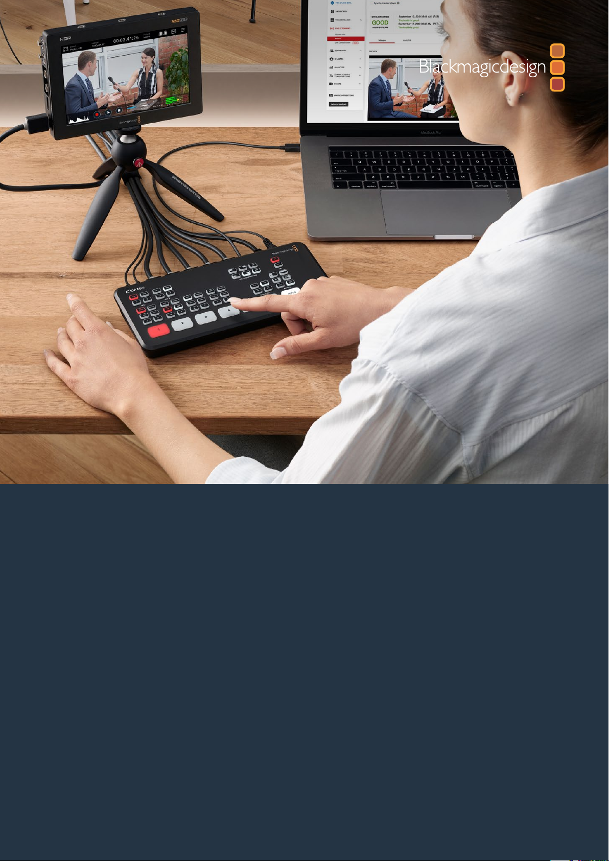
ATEM Mini’s control panel lets you switch video sources, adjust audio
levels, perform transitions and apply graphics and ef fects
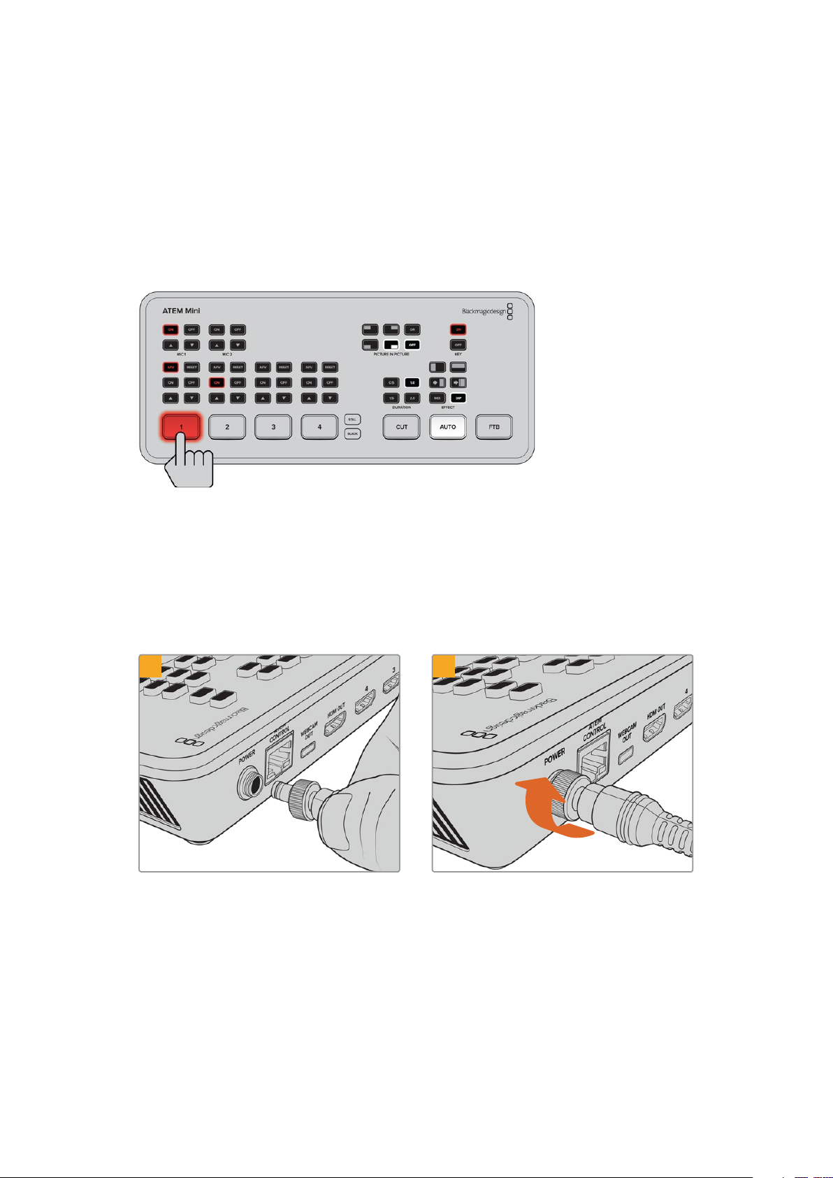
Plugging in Power
The first step to getting started is to plug in the mains power supply using the supplied power
adapter. Secure the connection to ATEM Mini by tightening the connector to the unit. This locks
the power cable to ATEM Mini preventing it from being accidentally removed.
1 2
Connec t power to ATEM Mini’s power
input using the supplied cable
Secure the connec tor to ATEM Mini by
tightening the connector screw
5Getting Started
Page 6
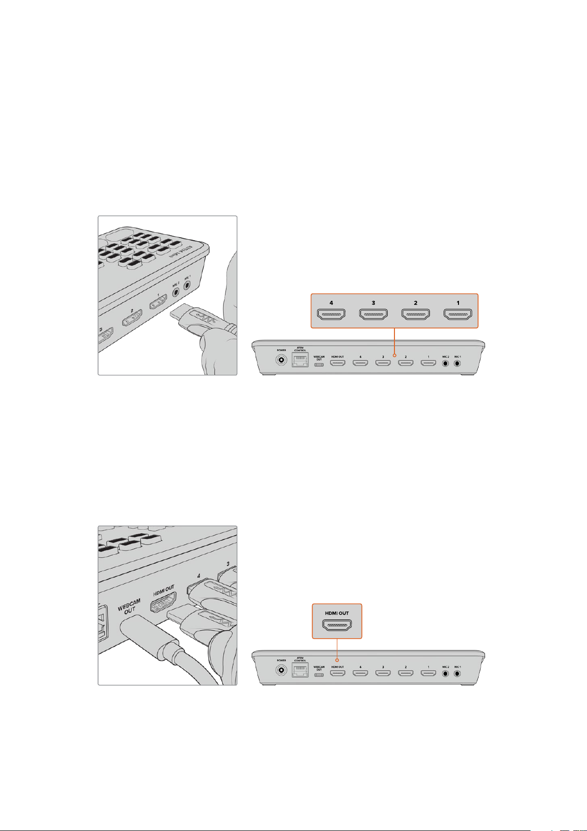
Plugging in Video Sources
Plug your HDMI cameras and other HDMI sources into ATEM Mini’s HDMI inputs. This gives you
four different images to switch to when creating your program. Simply plug one end of the
HDMI cable to your camera and the other end to any of ATEM Mini’s HDMI inputs. The first input
you plug in will set the video format, so if the first video source you plug in is 1080p50, all other
inputs will automatically be converted to 1080p50.
If you want to set the video format yourself after plugging in all video sources, you can do that in
the switcher settings in ATEM Software Control. You can find more information about changing
the video format settings in the ‘using ATEM Software Control’ section.
Plug HDMI sources into ATEM Mini’s four HDMI inputs
Plugging in a Monitor and Testing Inputs
With your video sources connected, you can now plug an HDMI television into ATEM Mini’s
HDMI output and check all the inputs are working. This is also a good opportunity to check
sources and see if your shots are smoothly switching between each other.
To check your sources, simply press the numbered input buttons on ATEM Mini’s control panel
and watch the HDMI television. If your sources are working correctly, you should see them
switch between each other when you press the input buttons.
Plug an HDMI television or monitor into ATEM Mini’s HDMI output so you can
monitor your program output and check all your sources are working properly
6Getting Started
Page 7
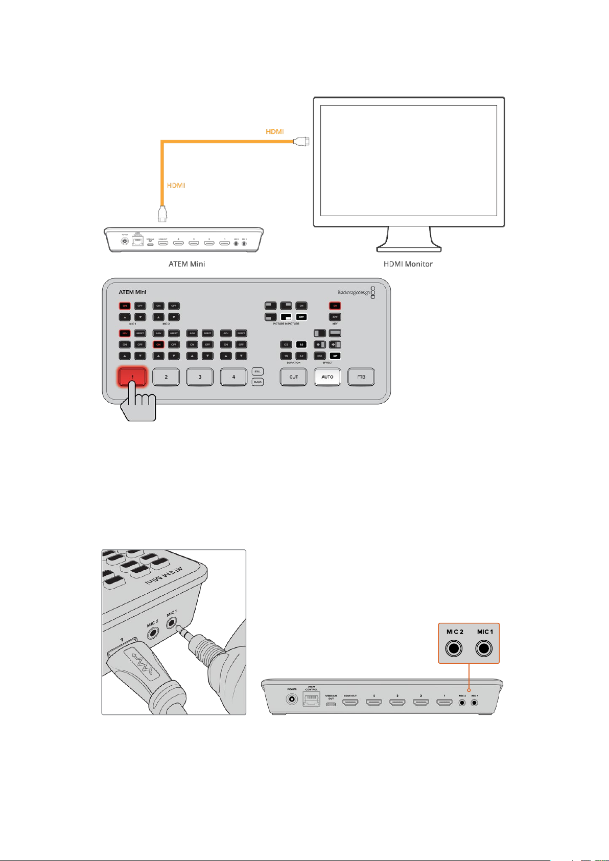
Connect a Microphone
When broadcasting a PowerPoint presentation or a kickstarter video, you might want to use a
microphone so your voice can be heard loud and clear. Plug a microphone, for example a small
wireless collar microphone, into one of the 3.5mm audio inputs.
If you are broadcasting an interview, plug the second microphone into the second 3.5mm
audio input. You can even plug a music player into one of the audio inputs and mix it into
your production.
Connect microphones to ATEM Mini’s mic inputs
7Getting Started
Page 8
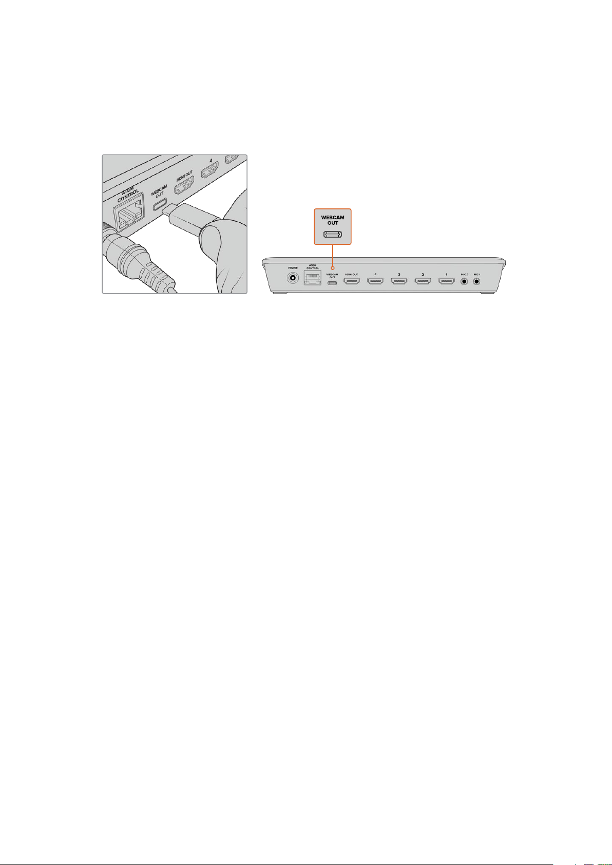
Connect your Computer
Plug ATEM Mini’s webcam output into your computer’s USB input. Now your computer will
recognize ATEM Mini as a webcam so you can select it as the webcam source in your streaming
program, such as Skype or OBS Studio.
Plug your computer into ATEM Mini’s webcam out USB-C connec tor
Setting the Webcam Source
In most cases, your streaming software will automatically set ATEM Mini as the webcam, so
when you launch your streaming software you will see the picture from your ATEM Mini
straight away. If your software doesn’t select ATEM Mini, simply set the software to use
ATEM Mini as the webcam and microphone.
Below is an example of how to set the webcam settings on Skype.
1 In Skype’s menu bar, open the ‘audio and video settings’.
2 Click on the ‘Camera’ drop down menu and select Blackmagic Design from the list.
You will see the video from ATEM Mini appear in the preview window.
3 Now go to the ‘microphone’ drop down menu and select Blackmagic Design as your
audio source.
With your Skype settings set correctly, perhaps try out a Skype call with a friend as a quick test
to check your broadcast setup is working.
That’s all you need to do and ATEM Mini is now ready to broadcast your video to the world live!
Using Open Broadcaster
Open Broadcaster is another streaming platform that takes your program video and streams it
live via your favourite video sharing application, like YouTube or Vimeo.
For information on how to set up Open Broadcaster with your ATEM Mini, refer to the ‘Setting up
Open Broadcaster’ section in this manual.
Switching your Production
Now that you have your cameras and microphone connected and your streaming software sees
ATEM Mini as a webcam, ATEM Mini is ready to start switching your production. This happens
when you switch from one video source in your broadcast to another. A source can be any
HDMI video signal connected to the HDMI inputs. It can also be a still graphic, a keyer, or any
internal source like a color generator, color bars, or black.
8Switching your Production
Page 9
With ATEM Mini, you can switch cleanly using professional cuts or transitions. For example,
a cut will instantly change from one source to another and a transition will change sources over
a defined duration often using an effect. For more information, refer to the ‘using cuts and
transitions’ section later in this manual.
Using Cuts and Transitions
When switching video sources, you can use a straight cut which will immediately change one
source to another, or a transition which gradually changes one source to another over a defined
duration. Transitions appear as an effect, for example a cross dissolve or mix, a dip to colour, or
even a stylized wipe and you have many styles to choose from.
Switching Sources using a Cut
In the demonstration below ATEM Mini will cut from input 1 to input 2.
To perform a cut:
1 Input 1 is illuminated red to indicate input 1 is currently live on air.
2 Select a ‘cut’ by pressing the ‘cut’ button. Pressing ‘cut’ tells ATEM Mini
you want to use a straight cut instead of an auto transition.
3 Now press the input 2 button.
Input 1 will now immediately switch to input 2 and you will see input 2 illuminated red,
which means input 2 is now live on air. This is known as a cut as you are ‘cutting’ directly
from one source to another.
Switching Sources using an Auto Transition
Transitions let you smoothly switch from one source to another over a defined duration.
For example, a mix transition gradually fades the current source into the next until the original
source is no longer visible. For example, a wipe transition will move a line across the original
source revealing another effectively wiping across the image. You can add a colored border,
or make it soft so the edge is smooth and pleasing. You can even use digital video effects or
DVEs, such as a squeeze or push, to move the images as they transition from one to the other.
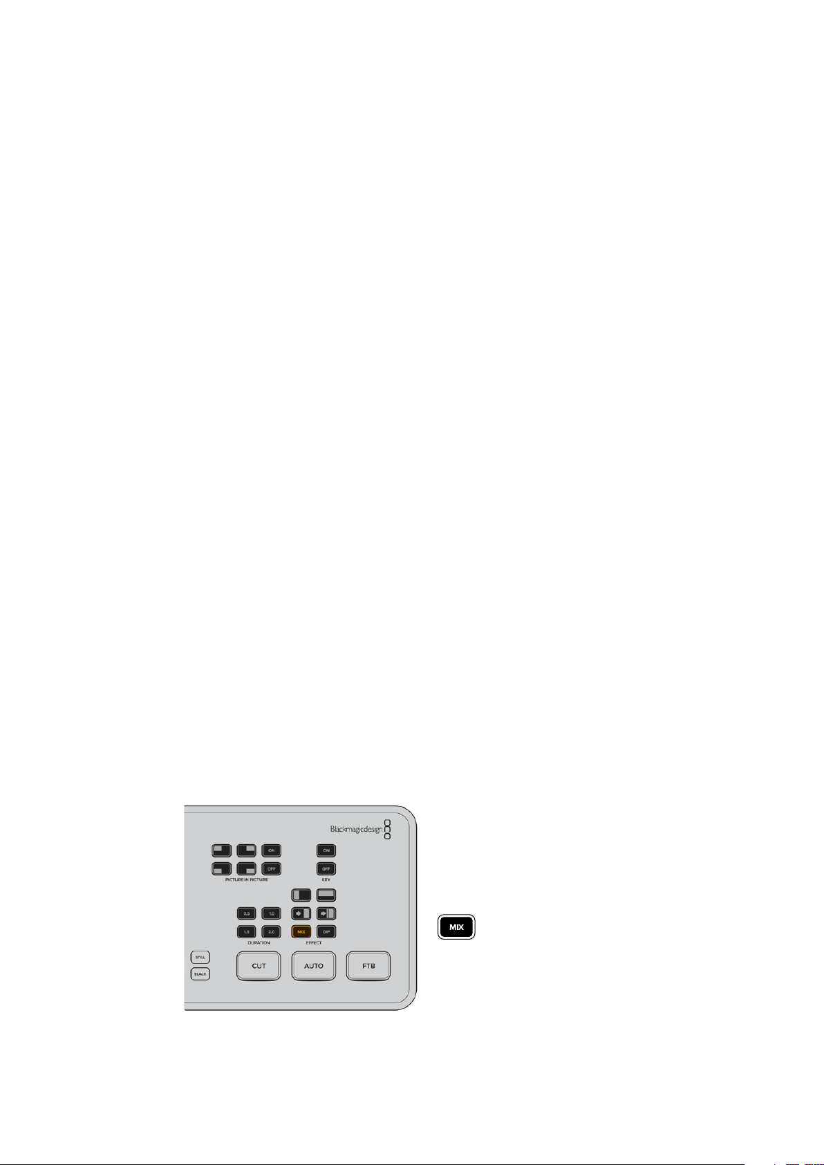
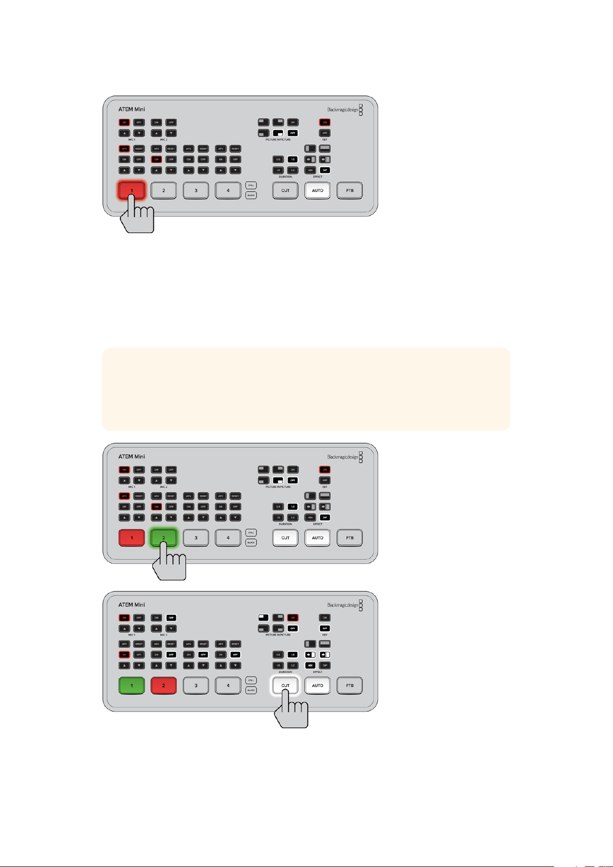
In the demonstration below ATEM Mini will switch from input 1 to input 2 using a mix transition:
To perform a mix auto transition:
1 Press the ‘mix’ button to select a mix transition.
9Switching your Production
Page 10
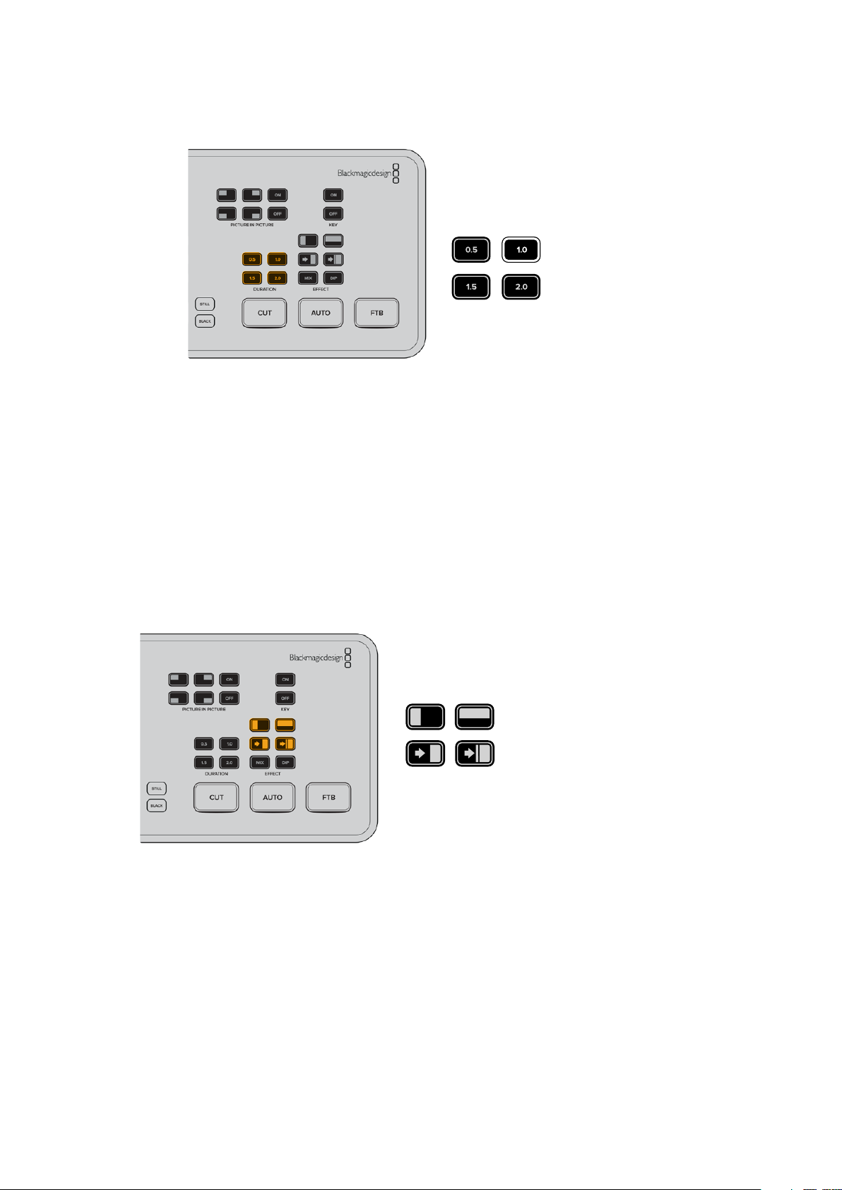
2 Now press a duration you want for the mix.
3 Press the ‘auto’ button to tell ATEM Mini you want to use an automated transition.
4 Press the input 2 button to perform the mix transition.
You will now see inputs 1 and 2 buttons illuminated red while the transition happens and your
broadcast changes to input 2. When the transition is complete, input 2 will be illuminated red
to indicate it is now live on air.
Transition Styles and DVEs
The buttons above the ‘auto’ button contain different transition styles, including a mix cross
dissolve and a dip to color.
You can also select horizontal and vertical wipe transitions by pressing their respective
transition style buttons. These also include DVE push and squeeze transitions.
Press the transition type button for the transition you
want to use, for example a horizontal or vertical wipe,
push or squeeze DVE transition, and mix or dip transition
Controlling Audio
When setting up your production or during your broadast, you will likely want to control audio
levels if the sound is too quiet or too loud.
When an audio level is too loud it will clip. Clipping means the audio has increased beyond the
maximum accepted level and when this happens it can distort and sound unpleasant.
10Switching your Production
Page 11
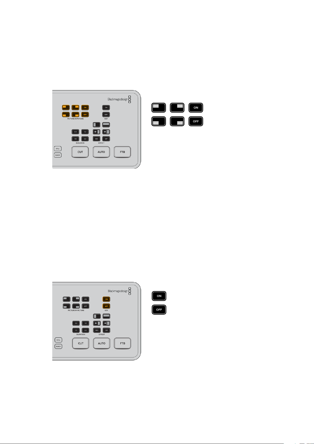
Pressing the up and down arrow buttons for each input will increase or decrease the audio
level for the respective source. For example, if the presenter’s voice is too loud and risks
clipping, you can decrease the audio level by pressing the down button incrementally until
the level is safe.
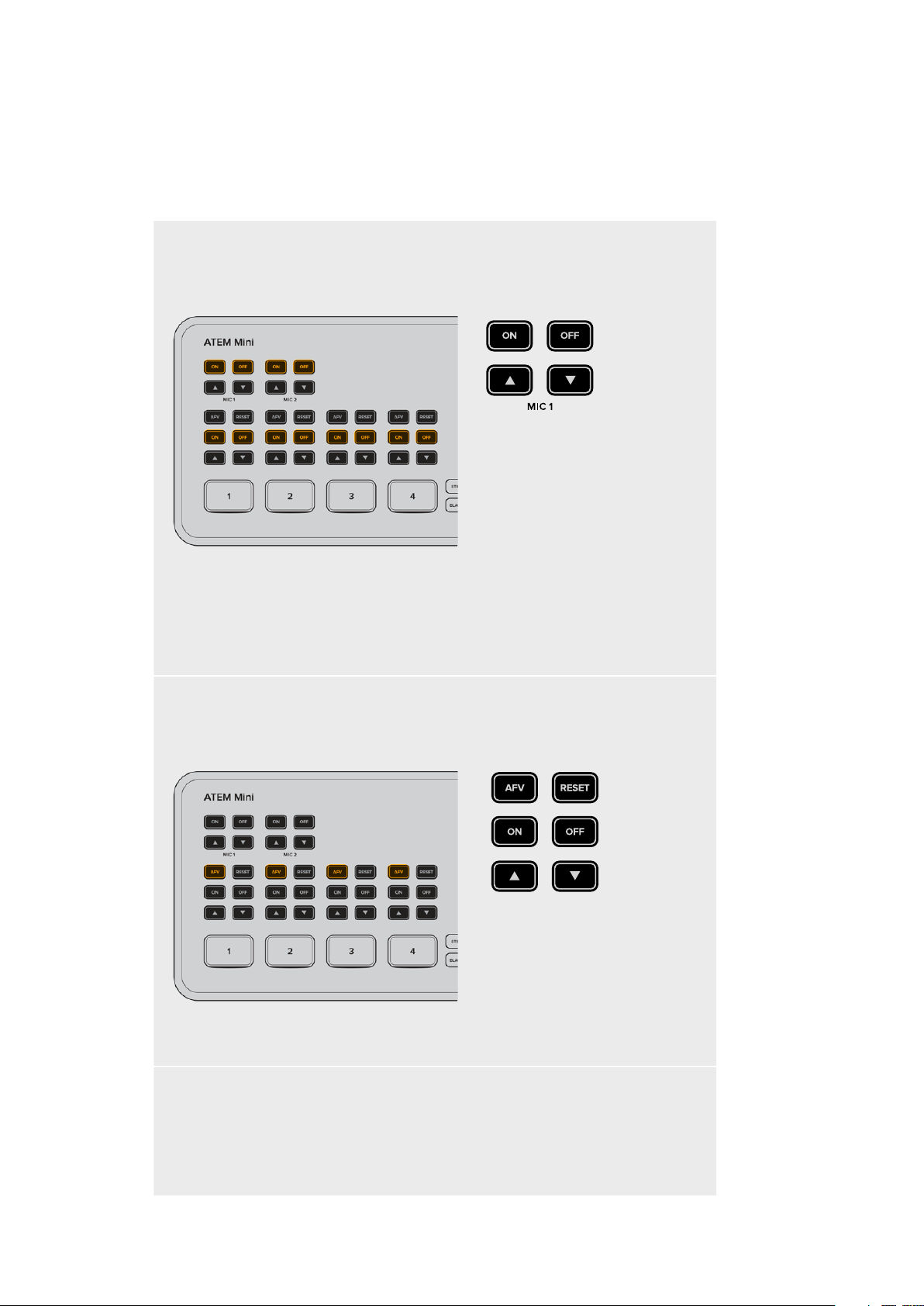
ON OFF
Pressing the on or off buttons will let you permanently enable the audio
from the respective input source, or turn its audio off completely.
ON – When the input’s audio is set to ‘on’, the input audio will be heard permanently,
even if the source is not currently on air.
OFF – When the input’s audio is set to ‘off’, the source audio will never be heard even if
the source video is on air.
AFV
AFV stands for ‘audio follows video’ and will let the audio for a respective input be heard
whenever the source is switched on air.
To enable or disable AFV for each input, simply press its AFV button.
Reset
Pressing the ‘reset’ button will restore the input audio level to its default position. This is
helpful if you want to cancel any adjustments or reference the original level before you
made changes.
11Switching your Production
Page 12
Using Picture in Picture
Picture in picture superimposes a second source over your broadcast video source in a small
box you can position and customize. Input 1 is the default picture in picture source, so if you’re
broadcasting gameplay and want to superimpose your reactions, plug your camera into input 1
and it will appear in picture in picture.
To enable picture in picture:
1 Make sure your video to be inside the box is plugged into HDMI input 1.
2 Plug your main video into HDMI input 2, 3, or 4.
3 In the picture in picture buttons on control panel, press ‘on’.
You will now see the picture in picture box appear on the screen. To select a different position,
press any of the position buttons.
Using the Upstream Keyer
ATEM Mini’s upstream keyer is used to superimpose graphics or blend one video layer over
another using transparency. This means you can tell ATEM Mini to make an input source’s
background color invisible using the chroma keyer, or only use a specific section of a graphic
using a luma or linear key. Linear keys are great for visual effects, titles and lower third graphics.
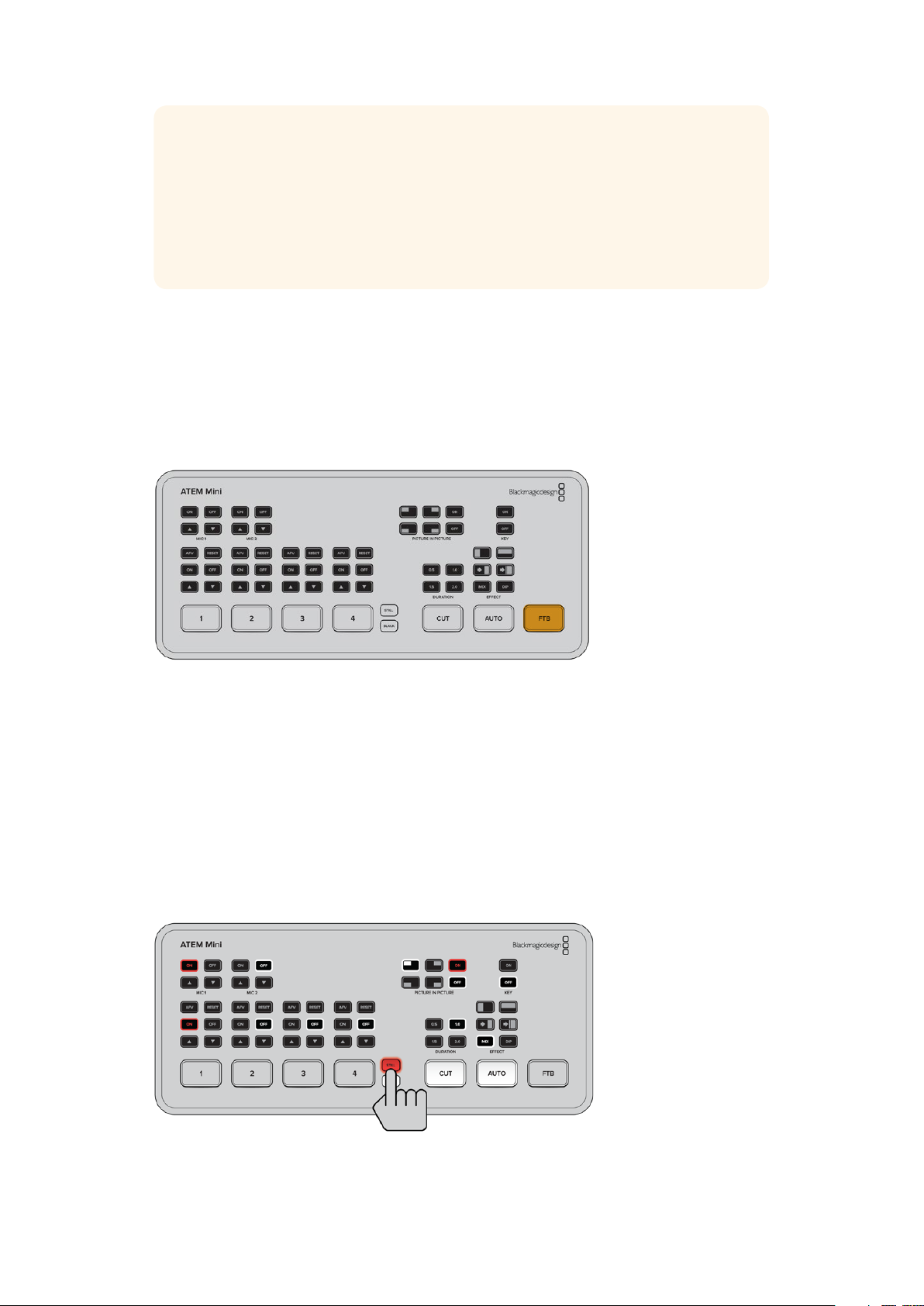
Press the ‘key’ on or of f but tons to switch the
upstream keyer on and off air
12Switching your Production
Page 13
TIP ATEM Mini’s advanced chroma keyer is perfect for keying graphics from a
PowerPoint presentation. For example, you could have a series of graphics designed
to be keyed over a background and these can played out directly from a PowerPoint
sequence. All you need to do is make any invisible areas green, or any solid color that
isn’t used in your graphic, then set the chroma keyer to make that color transparent.
The images from your computer will be high quality over HDMI so will key very cleanly
and look fantastic.
Fade to Black
The fade to black button is an easy way to start and end live broadcasts. Fade to black
performs a mix to black which happens across all video layers at the same time. This means all
video inputs, stills and any upstream or downstream keyers that are visible in your broadcast.
When performing a fade to black, the master program audio will also fade out to silence.
Simply press the FTB button to perform the fade to black. The button will flash while enabled.
To fade up from black, simply press the FTB button again. This is a clean way of starting and
finishing a broadcast.
Using a Still Graphic
The ‘still’ button is another input source you can switch to in your production. Simply press the
‘still’ button to switch a still loaded in the media player to air.
To take the graphic off air, simply switch to a different input source.
The ‘still’ button will switch a graphic loaded in ATEM Software Control’s media pool.
ATEM Software Control is an extremely powerful software control panel that opens a
world of options and lets you do a lot more with ATEM Mini.
13Switching your Production
Page 14
ATEM Software Control
ATEM Software Control is a powerful software control panel that gives you a lot more control
over your ATEM Mini. Once you start using ATEM Software Control you will quckly see just how
much your ATEM Mini can actually do.
For example, you can manually perform transitions using the fader bar, select internal sources
on the program and preview buttons, mix audio using a mixer with channel faders, set up
keyers, load graphics in the media pool and much, much more.
ATEM Software Control is included with your ATEM Mini and allows you to control your switcher
in a similar way to a full hardware control panel. A range of palettes on the right side shows you
all processing features of your ATEM Mini and allows settings to be easily made.
You can also use ATEM Software Control to configure your switcher settings. For more
information on how to use ATEM Software Control, refer to ‘using ATEM Software Control’
in the following sections of the manual.
Switching Modes
‘Cut bus’ is the default switching mode which lets you change sources as soon as you press an
input button. Setting ATEM Mini to ‘program preview’ mode lets you preview the source before
switching it to air.
Cut Bus
In cut bus mode, as soon as you press an input button, it will immediately switch to air.
This is a fast and easy way of switching.
14Switching your Production
Page 15
In cut bus mode, pressing an input but ton will instantly switch it to air
Program Preview
In program preview mode, switching a source is a two step process. This is because pressing
an input button puts the source in a preview state so you can decide whether you want to
switch it, or perhaps select a different input source. This powerful switching mode is used by
professional broadcast switchers across the world.
TIP If you connect an HDMI monitor, for example Blackmagic Video Assist, to
ATEM Mini’s HDMI output you can output the preview signal and monitor the
selected input before switching it to air. For more information, refer to the ‘setting
the HDMI output’ section later in this manual.
In program preview switching mode, press an input button and then
press the ‘auto’ or ‘cut’ button to switch the source to air
15Switching your Production
Page 16
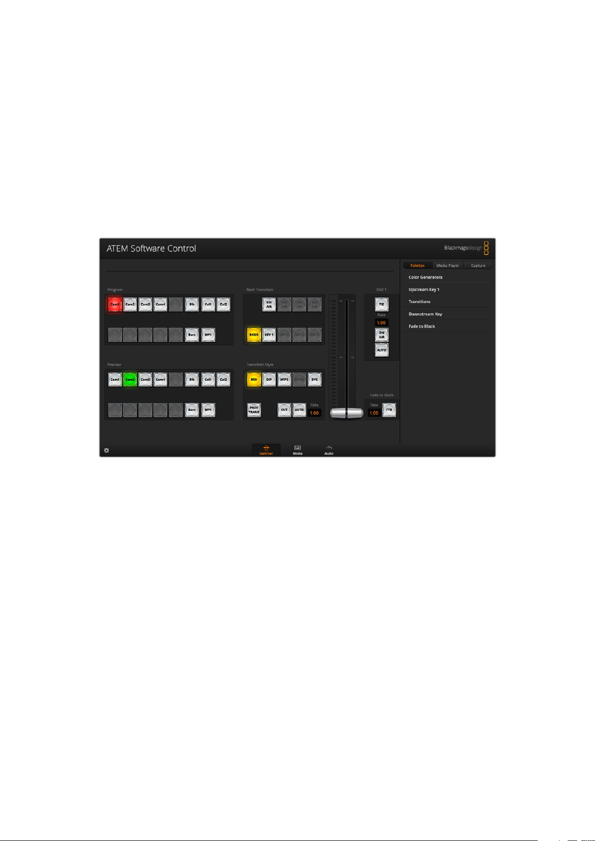
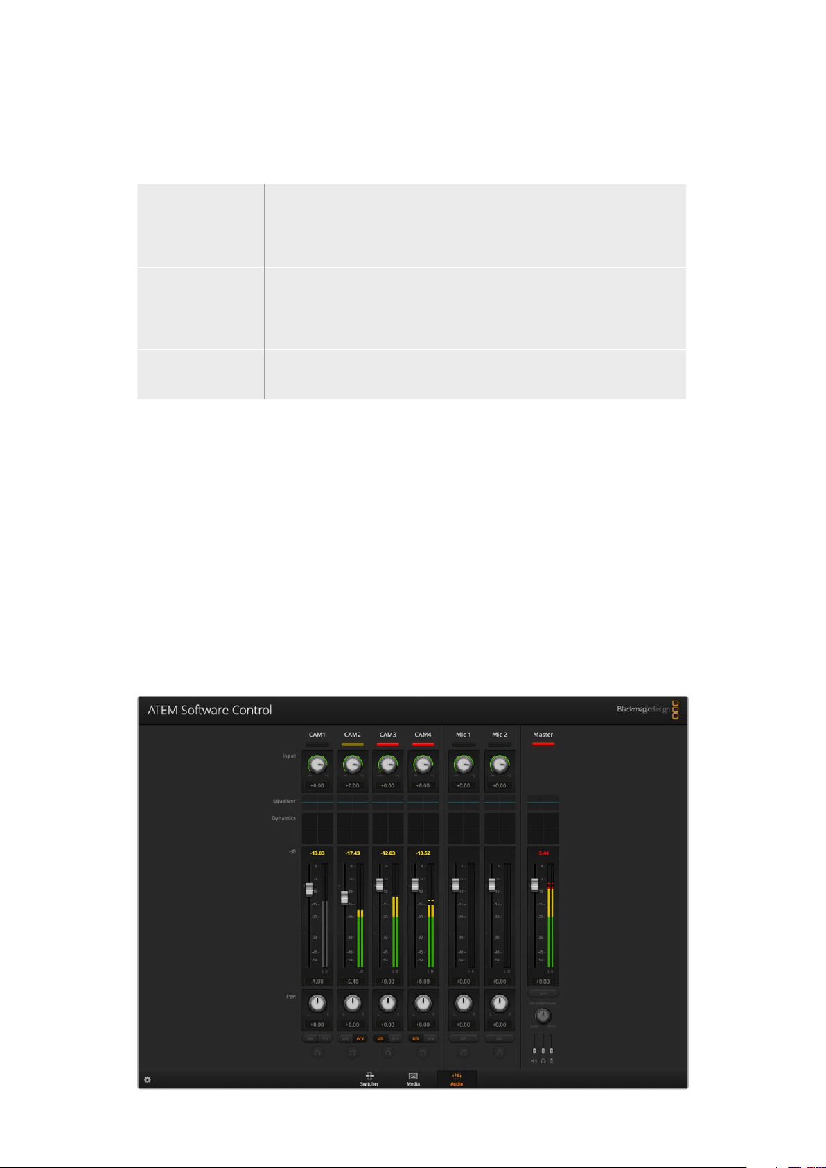
Using ATEM Software Control
ATEM Software Control has three main control windows: Switcher, Media and Audio. You can
open these windows by clicking the three main buttons at the bottom of the interface or by
pressing the Shift and left/right arrow hot keys. A general settings window can be opened by
selecting the gear icon at the lower left of the interface.
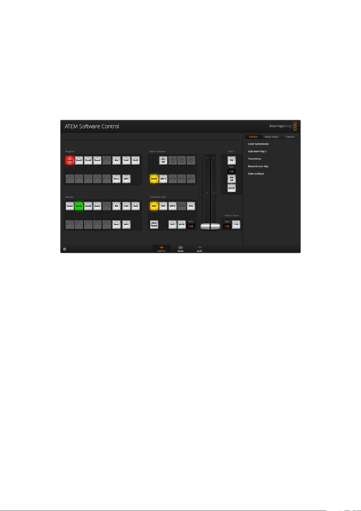
Switcher Panel
When first launched, the switcher screen is selected, which is the main control interface for
the switcher. ATEM Mini must be connected to your computer via USB for the software control
panel to run.
Mouse or Trackpad Operation
The virtual buttons, sliders and fader bar on the software control panel are operated using your
computer mouse or a trackpad if you’re using a laptop.
To activate a button, click once with the left mouse button. To activate a slider, click and hold
down the left mouse button while dragging. Similarly, to control the fader bar, click and hold
down the left mouse button on the fader bar handle and drag up or down.
Media Manager
The media manager allows you to upload graphics to the media pool in ATEM Mini. Your
ATEM Mini has memory for graphics that’s called the media pool and holds up to 20 still
graphics with alpha channel that can be assigned to a media player for use in your production.
So, for example, you could have the maximum 20 still graphics loaded that will be used on your
live production and then assign various stills to the media player as you work. As you take a
graphic off air, you can change the media player graphic to the next graphic you want, and then
you can put that media player back on air with the new graphic.
When a still is loaded into the media pool, the alpha channel is loaded automatically if one is
included in the image. When a still is loaded into a media player, the output of the media player
will include both key and fill outputs. If you select the media player as a key source, for example
Media Player 1, both the fill and the key are automatically selected so you don’t have to select
16Using ATEM Software Control
Page 17
them separately. However the key can still be routed separately so you can use a different
key source if you wish. To learn more about keying, refer to the ‘keying using ATEM Mini’
section of this manual.
Audio Mixer
The audio tab in ATEM Software Control contains a powerful audio mixer interface which
becomes active when controlling your ATEM switcher.
ATEM Mini includes a built in audio mixer that lets you use the embedded HDMI audio from your
cameras, media servers and other inputs without the need for an external audio mixer. This is
perfect when using your ATEM Mini on location or in small spaces within modern OB vehicles as
you don’t have to find room for an external audio mixer. The audio is mixed in the audio tab of
ATEM Software Control and output via the USB webcam output. You can also route the program
output via HDMI if you want to record your broadcast.
Your ATEM Mini also features built in mic inputs for mixing external audio.
If you prefer to use an external audio mixer, it’s easy to disable the audio for all inputs and you
only need to leave the external audio active in the audio mixer interface. More information on
how to use the audio mixer is included in the next sections.
Using the Software Control Panel
The switcher window is the main control interface for the switcher. During live production,
theswitcher window can be used to select sources and take them to air.
You can select the transition style, manage upstream/downstream keyers and turn on/off the
fade to black. The palettes on the right hand side of the interface are where you adjust
transition settings including transition rates, adjust color generators, control the media player,
andadjust the upstream and downstream keyer as well as control fade to black rate.
17Using ATEM Software Control
Page 18
Mix Eects
The Mix Effects block of the switcher tab contains all the source select buttons for the program
and preview buses, allowing external inputs or internal sources to be selected for next
transition previewing or switching to air.
ATEM mix effects
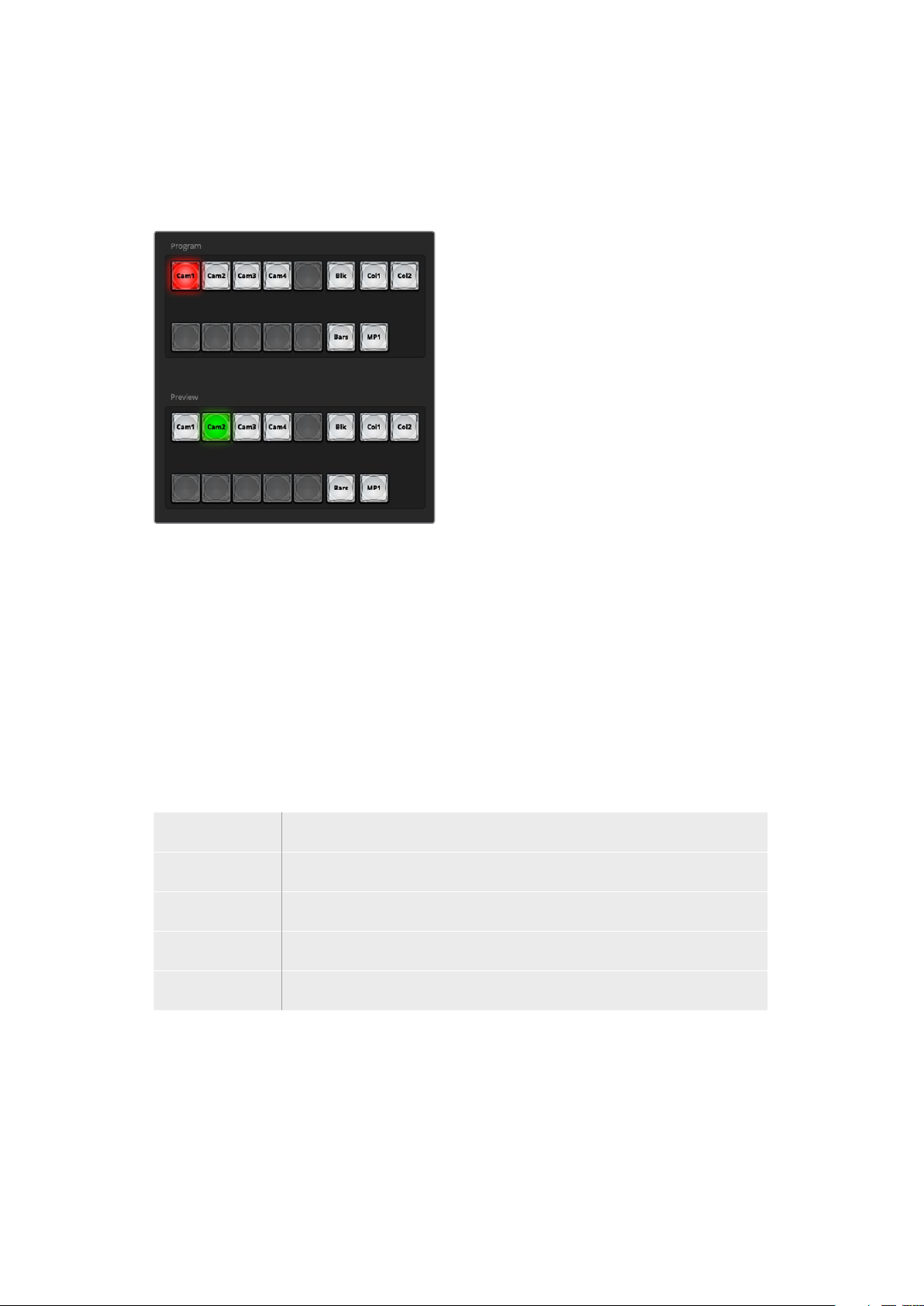
Program Bus Source Select Buttons
The program bus source select buttons are used to hot switch background sources to the
program output. The source currently on air is indicated by a button that is illuminated red.
Preview Bus Source Select Buttons
In program preview switching mode, the preview bus source select buttons are used to select a
background source on the preview output, this source is sent to the program bus when the next
transition occurs. The currently selected preview source is indicated by a button that is
illuminated green.
The source select buttons for the program bus match the preview bus.
INPUTS Input buttons match the number of external switcher inputs.
BLACK Black color source internally generated by the switcher.
BARS Color bars source internally generated by the switcher.
COLOR 1 and 2 Color sources internally generated by the switcher.
MEDIA 1 Internal media player that display stills stored in the switcher.
18Using ATEM Software Control
Page 19
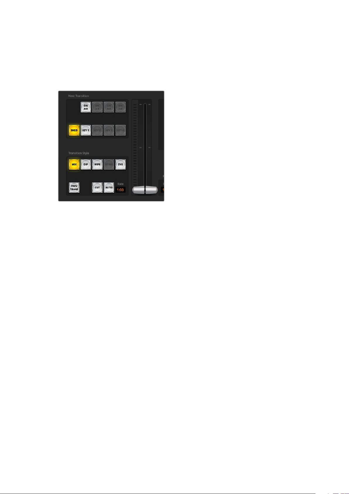
Transition Control and Upstream Keyer
CUT
The CUT button performs an immediate transition of the program and preview outputs,
overriding the selected transition style.
Transition control
AUTO/RATE
The AUTO button will perform the selected transition at the rate specified in the ‘rate’ display.
The transition rate for each transition style is set in the transition palette for that style and is
displayed in the ‘rate’ window of the transition control block when the corresponding transition
style button is selected.
The AUTO button illuminates red for the duration of the transition and the ‘rate’ display updates
to indicate the number of frames remaining as the transition progresses. When you perform a
transition using the fader bar on an external ATEM hardware panel, the fader bar indicator on
the software panel updates to provide visual feedback on the progress of the transition.
Fader Bar
The fader bar is used as an alternative to the AUTO button and allows the operator to manually
control the transition with a mouse. The AUTO button illuminates red for the duration of the
transition and the ‘rate’ display updates to indicate the number of frames remaining as the
transition progresses.
Transition Style
The transition style buttons allow the operator to select one of four types of transitions; mix,
dip, wipe and DVE. The selected transition style is indicated by a yellow illuminated button.
Selection of these buttons will be reflected by the corresponding tab in the ‘transitions’
processing palette. For example, when you have the transitions processing palette open and
click on a transition style button, the transitions palette will match your selection so you can
quickly adjust the settings.
PREV TRANS
The PREV TRANS button enables the preview transition mode, allowing the operator to verify
a mix, dip, wipe or DVE transition by performing it on the preview output using the fader bar.
When the PREV TRANS is selected you will see the preview output match the program output,
and then it’s simple to practice your selected transition with the fader bar to confirm you are
going to get what you want. This is a very helpful feature to avoid mistakes on air!
19Using ATEM Software Control
Page 20
Next Transition
The BKGD and KEY 1 buttons are used to select the elements which will transition on air or off
air with the next transition. More upstream keyers are available on 4K model ATEM switchers
and that is why other upstream keyers appear greyed out. The key can be faded on and off
when the main transition occurs, or you can select just the key to transition individually, so the
main transition control can be used to fade the key on and off.
When selecting the elements of the next transition, the switcher operator should look at the
preview video output because it provides an accurate representation of what the program
output will look like after the transition is completed. When only the BKGD button is selected,
a transition from the current source on the program bus to the source selected on the preview
bus will occur without the keyer. You can also select only keyer to transition, leaving the current
background live throughout the transition.
ON AIR
The ON AIR indicator button indicates when the key is currently on air and can also be used to
immediately cut the key on or off air.
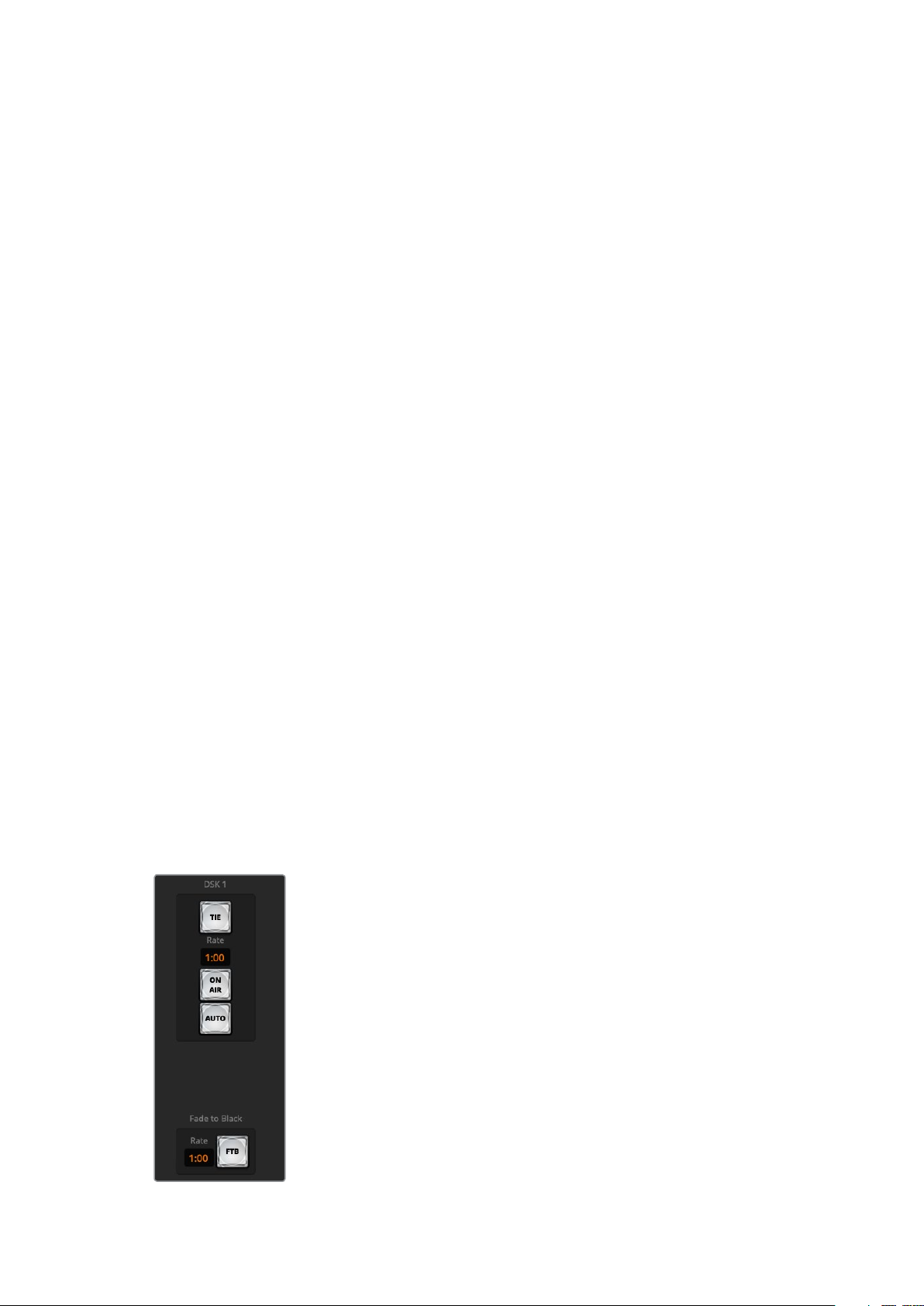
Downstream Keyer
TIE
The TIE button will enable the downstream keyer, or DSK, on the preview output, along with the
next transition effects and tie it to the main transition control so that the DSK can be taken to air
with the next transition.
The DSK will transition at the rate specified in the ‘rate’ display of the transition control block.
If the DSK is tied, the signal routing to the clean feed 1 is unaffected.
ON AIR
The ON AIR button is used to cut the DSK on or off air and indicates whether the DSK is
currently on or off air. The button is illuminated if the DSK is currently on air.
AUTO
The AUTO button will mix the DSK on or off air at the rate specified in the DSK ‘rate’ window.
This is similar to the main AUTO rate on the transition control block, however it’s limited only to
the downstream keyer. This can be used to fade up and down bugs and logos, such as live or
replay bugs during production, without interfering with the main program production transitions.
Fade to Black
Downstream key and fade to black
20Using ATEM Software Control
Page 21
The FTB button will fade the whole program video output to black at the rate specified in the
fade to black RATE window. Once the program output has been faded to black, the FTB button
will flash red until it is pressed again. Doing so will fade up from black at the same rate, or you
can enter a new rate in the fade to black palette in the ‘switcher’ window. Fade to black is
mostly used at the start and end of your production, or when cutting to commercial breaks. It
ensures all layers in ATEM Mini are faded down together. A fade to black cannot be previewed.
You can also set the audio mixer to fade the audio with your fade to black by selecting the
‘audio follow video’ checkbox in the fade to black palette, or by enabling the AFV button on the
master audio output fader.
Processing Palettes
The software control panel features tabs for the processing palette, media player, and capture
options. The capture option supports legacy model ATEM switchers with USB capture features.
TIP The palettes also show the order of the processing in the switcher. You can
expand and minimize palettes to save space and scroll them up and down to get the
adjustments you need to set.
The following processing palettes are available.
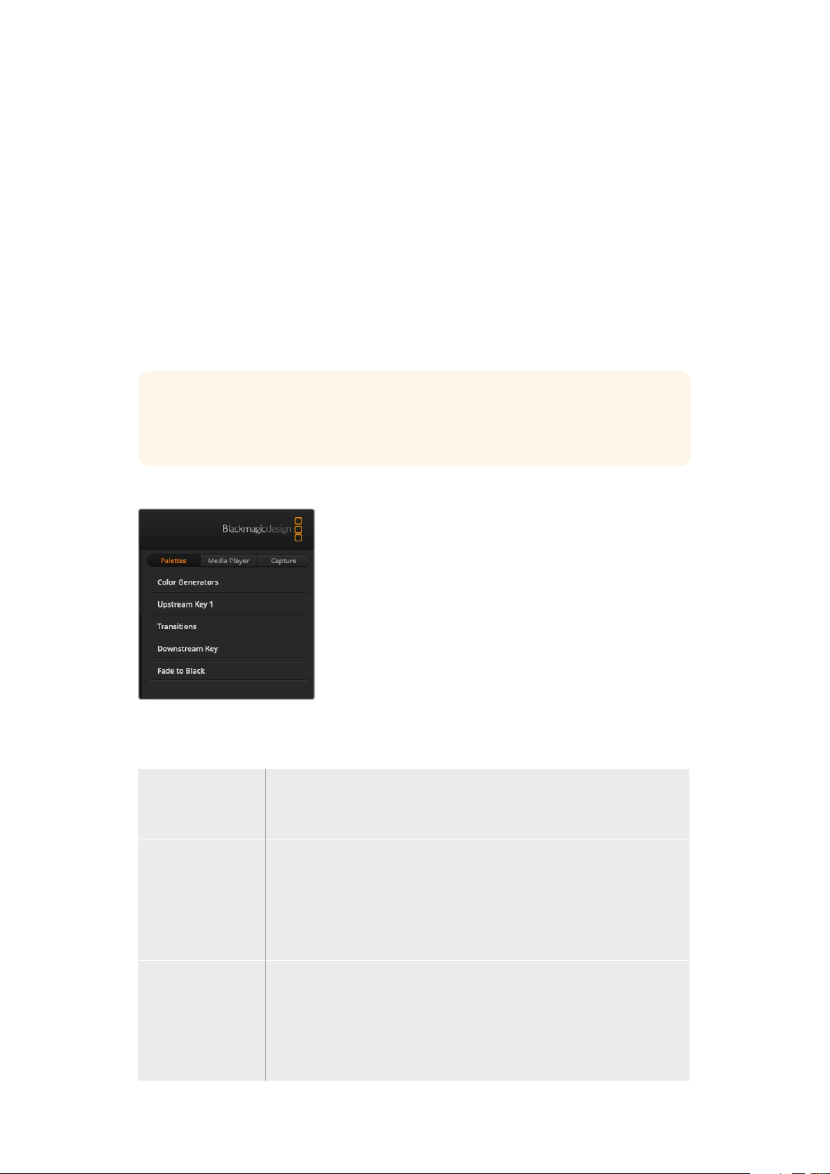
Palettes Tab
The ‘palettes’ tab contains the following processing controls.
Color Generators Your ATEM switcher has two color matte generators which can be configured
from the color generators palette using a color picker or by setting hue,
saturation, and luminance levels.
Upstream Key The switcher’s upstream keyer can be configured from the upstream key
palette. Within the keyer palette, the keyer can be configured as a luma key,
chroma key, pattern key or DVE. The type of key available will also depend
on if the DVE is available. The upstream key palette will display all the
parameters that are available to configure the keyer. More information on
how to use upstream keyer is included later in this manual.
Transitions The transitions palette is where you can configure the parameters of each
transition style. Forexample, for the dip transition the palette has a drop
down menu where you can select the dip source and for the wipe transition
the palette displays all the available wipe patterns. There are lots of
variations of transitions, and a large number of transitions can be created by
combining settings and features in the transitions palette.
21Using ATEM Software Control
Page 22
NOTE It’s worth noting that simply selecting a specific style of transition in this palette
will only adjust the settings for these transitions, and you still need to select the style
of transition you want to perform in the transition control section on the software or
ATEM Mini’s control panel. The software and ATEM Mini’s control panel work together
and mirror all settings, so you can use any combination you like!
Downstream Key ATEM Mini has a downstream keyer which can be configured from the
downstream key palette. The palette has drop down boxes for selecting the
fill and key signals to the keyer, plus sliders to set the pre multiplied key clip
and gain values, and mask settings.
Fade to Black The fade to black palette is where you can set the fade to black transition
rate. An ‘Audio Follow Video’ checkbox is also provided as a shortcut for the
audio mixer’s master fader AFV button. Selecting this feature lets you fade
your audio with your fade to black.
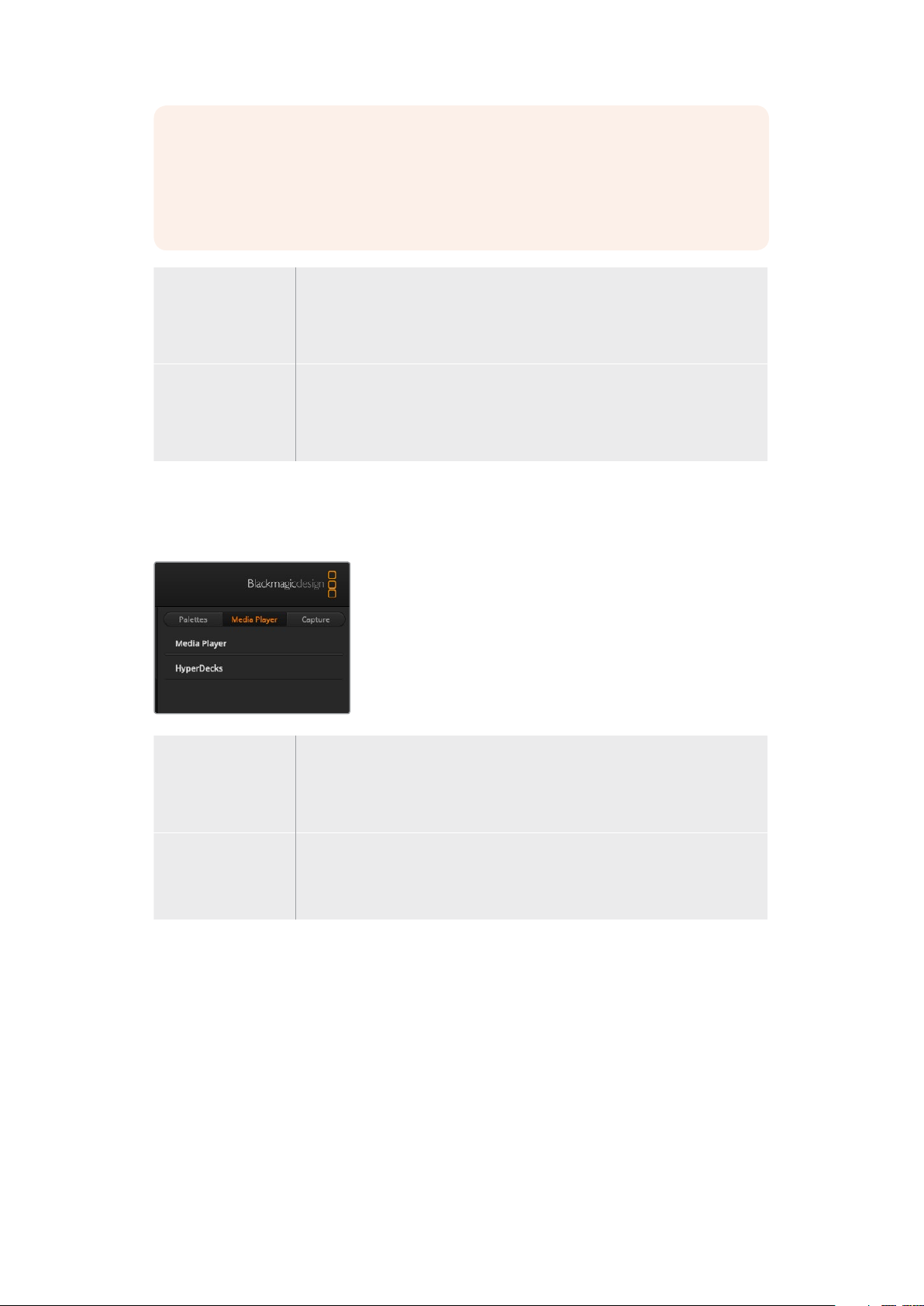
Media Player Tab
The ‘media player’ tab contains controls for your ATEM Mini’s media player and connected
HyperDecks.
Media Player Your ATEM Mini has a media player that plays back the stills that are stored in
the media pool memory built into the switcher. The drop down list is used to
select the still that will be played or made available on the media player input
to the switcher.
Hyperdecks You can connect up to 4 Blackmagic HyperDeck Studio model disk recorders
and control them using ATEM Software Control’s HyperDecks palette.
For more information refer to the ‘HyperDeck Control’ section of this manual.
Capture Tab
The capture tab supports the original ATEM production switchers that feature
USB output recording.
The capture tab lets you capture stills and set the timecode window.
Capture Still
If you need to capture a still image from your broadcast simply click on the ‘capture still’ button.
This acts like a still store which lets you add capture files to the media pool. You can then
immediately load a still into the media player and use it in your broadcast, or save the media
pool to your computer.
22Using ATEM Software Control
Page 23
To save the media pool:
1 Go to the menu bar at the top of your screen and click on ‘file/save as’.
2 Choose the location you want to save to.
3 Click ‘save’.
Now that your media pool is saved on your computer, you can access the captured stills and
use them in your graphics software.
Timecode
The timecode window provides a timecode counter that runs from the moment you power your
ATEM Mini. The counter can also be set manually.
To set the counter:
1 Click on the ‘set timecode’ edit box underneath the counter. An orange border will
appear when the box is enabled.
2 Type in a manual timecode.
3 Click the ‘set’ button.
The counter will now run timecode from your manually set values.
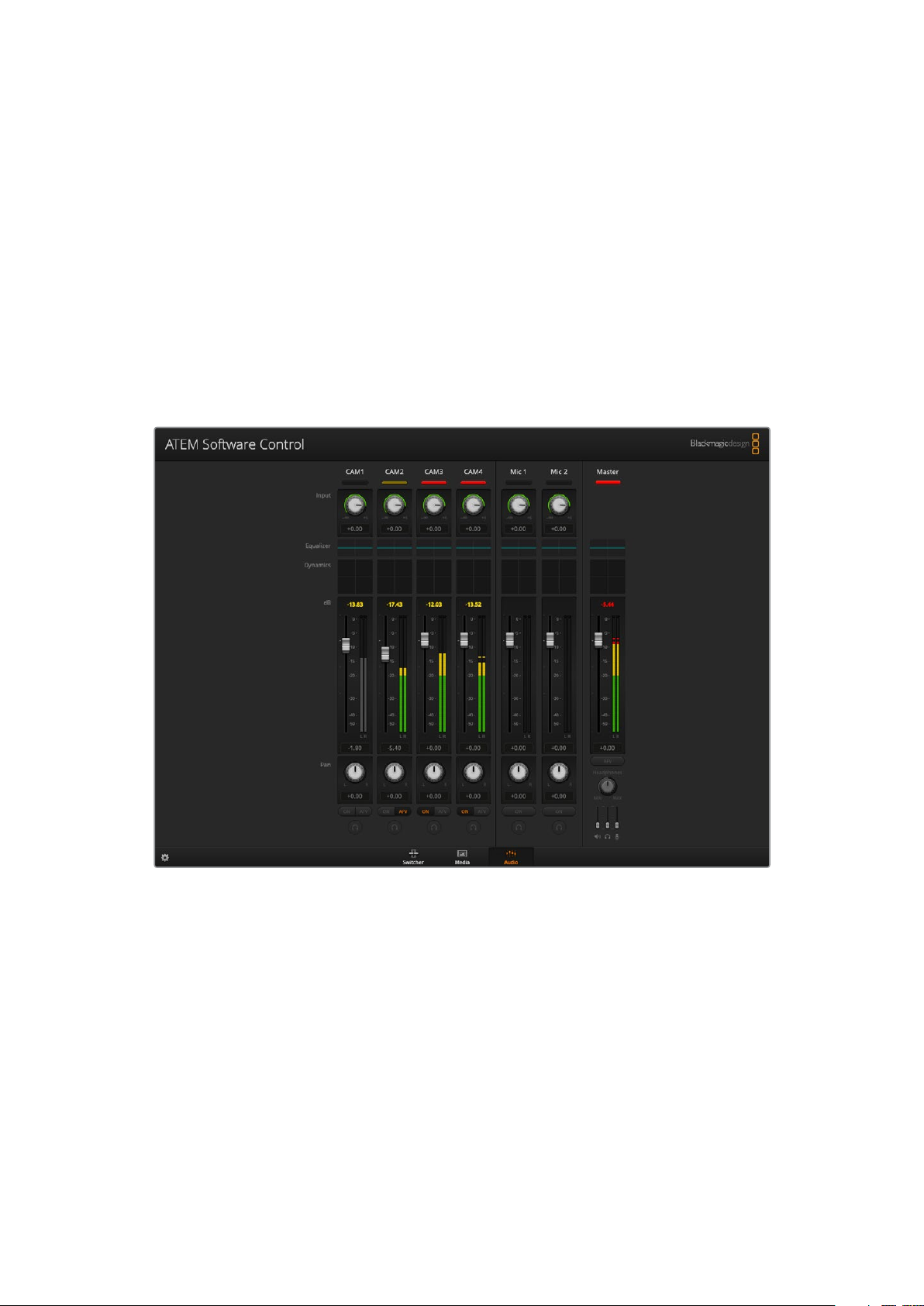
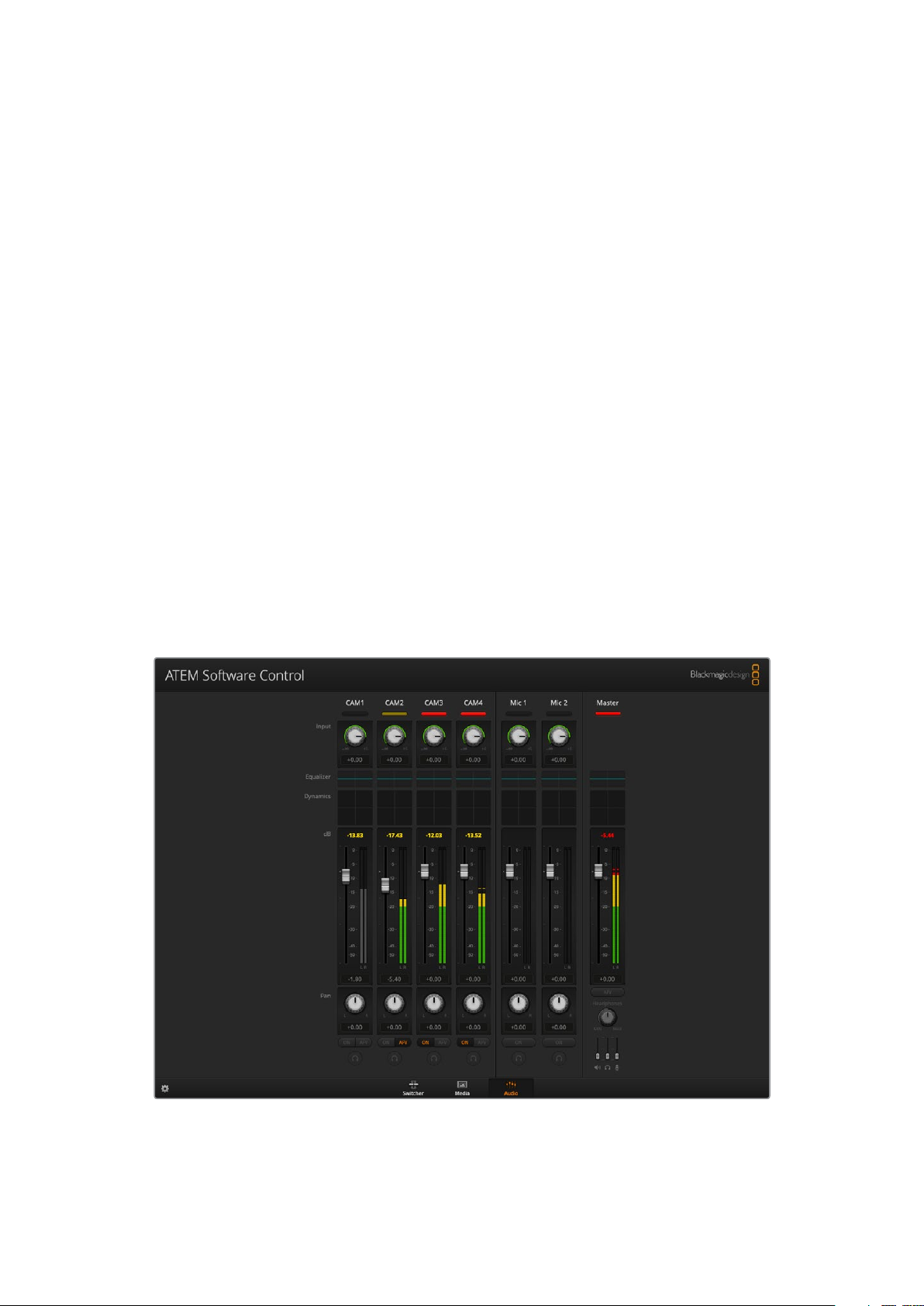
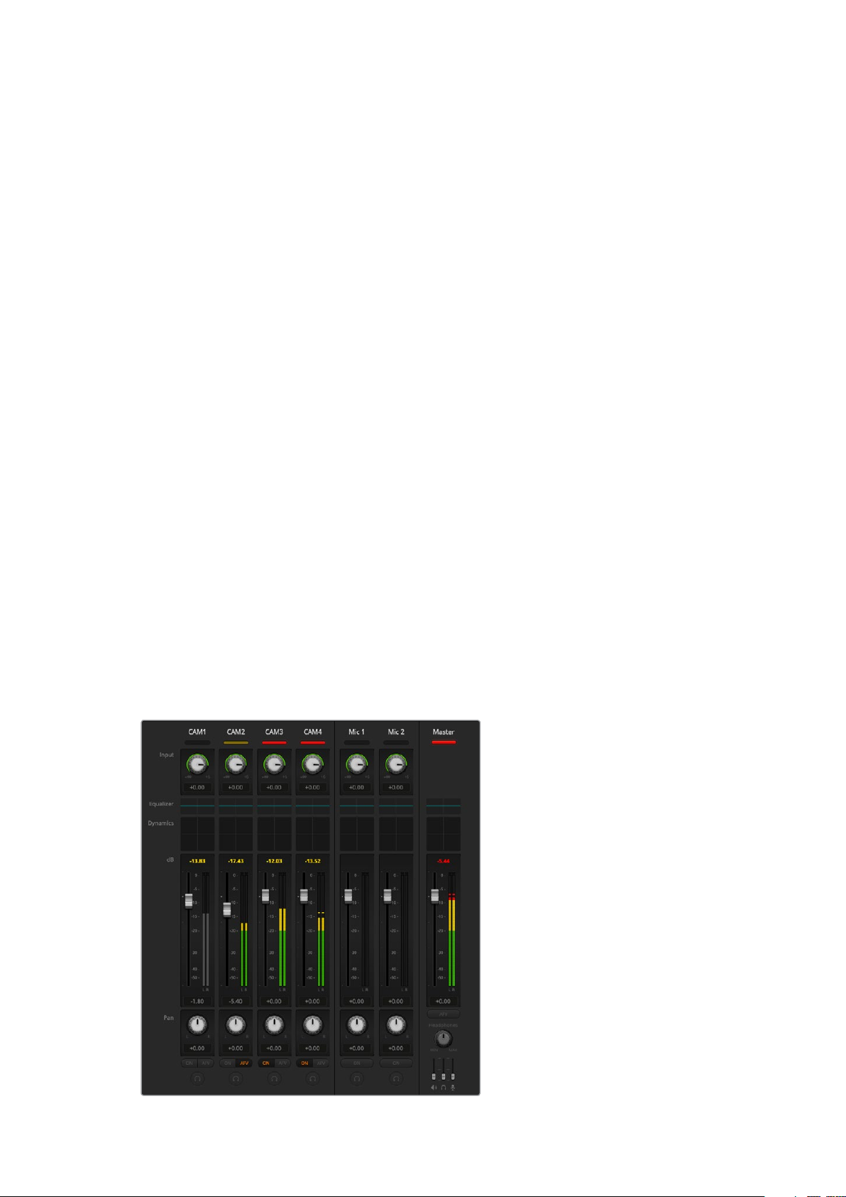
Using the Audio Mixer
The audio tab is used to mix audio sources connected to ATEM Mini via HDMI and mic audio.
Cameras and external mic audio sources are listed along the top of the audio mixer along with
the master audio output for the USB webcam program output to your computer.
The audio mixer displays tally lights for any audio sources that are currently on air or when AFV is
selected, as well as audio level, audio balance and buttons for selecting which audio should be used
23Using ATEM Software Control
Page 24
Below each audio source is an audio level meter, a fader for setting the maximum audio level,
and a knob for setting the left/right audio channel balance. The master fader on the right side of
the audio mixer is used to set the gain on the audio level on the USB webcam program output
and has its own audio level meter. Next to the master fader are mic faders which let you control
the audio level for microphones connected to the mic inputs.
The buttons below each audio level meter determine whether audio is always available for
mixing or only when the source is on air.
The solo monitoring feature for each input is greyed out as it supports ATEM Production Studio
and Broadcast Studio model switchers.
Tal l y
Any source whose audio is on air is lit with a red tally light in the software. In the example on
this page, camera 3 and camera 4 are lit because their audio is set to be always on. The tally
light will be illuminated dull yellow when AFV is selected and the channel’s associated camera
is off air. This also applies to the master fader tally light when the master fader AFV button is
selected. When FTB is activated, the master fader tally light will blink red.
Audio Level
Drag the audio level fader to set the gain on the audio level for each camera and audio source.
The numbers under each audio level meter show the maximum audio level set by the fader.
The numbers above the audio meter show the peak audio level reached by the audio source.
A green number represents low to medium audio levels.
If the audio meter is regularly showing red, and the red number above it is not changing, then
you should reduce the audio level to avoid audio distortion. After adjusting the audio level, you
may wish to reset the red number by clicking on it once. Observe the new number to make sure
it changes for a while and does not immediately shoot up and become stuck on a red number.
If it does, you may need to reduce the audio level even further.
Audio Balance
The audio mixer supports stereo audio from each audio source. If you wish to change the left
and right audio channel balance for a camera or other audio source, adjust the knob to the
desired balance point.
The audio meter for Cam1 is shown in
gray to indicate that its audio will not be
used as neither of its ON or AFV buttons
are enabled. Cam2 has AFV selected
but its audio is not currently being used
as the camera is not on air as is indicated
by its dull yellow tally light. Cam3 and
Cam4 have their direct mix set to ON
so their mixed audio is always used and
their tally lights remain lit, even if another
camera is currently on air. The audio
level meters for Mic 1 and Mic 2 show
that no audio is present on these inputs.
24Using ATEM Software Control
Page 25
Audio Source Selection
Below each audio level meter, you will find the ON and AFV buttons that select which audio
sources are sent to the program output of the switcher.
ON Selecting the direct mix to ON allows an audio input to be permanently
mixed into the program output, even when the associated video source is not
on air. The red tally light will always be lit because the audio is always on air.
Selecting this option automatically disables AFV.
Audio Follow Video Audio follow video allows audio to crossfade when inputs change. The audio
will only be sent to the program output when the input is on air, lighting the
red tally light above. When off air, the tally light is lit dull yellow. Selecting this
option automatically disables the direct mix ON setting.
SOLO The solo feature appears as a headphones icon below each input and is
available for ATEM Production Studio and Broadcast Studio model switchers.
Master Audio Level Output
The master fader on the right side of the audio mixer is used to set the gain on the audio level
for the USB webcam program output and has its own audio level meter. Select the AFV button
on the master audio output fader to enable the AFV fade to black feature. This lets you fade
your master audio when you click on the fade to black button.
Audio Mixer Monitor
The monitor headphones sliders appear below the master fader and control the monitoring
audio output behavior on ATEM Television Studio model switchers.
Shaping your Audio Mix using Advanced Fairlight Controls
ATEM Mini has advanced Fairlight audio controls that let you enhance and refine the quality of
sound on each input and master output, including input level controls, a 6 band parametric
equalizer and powerful dynamics settings.
25Using ATEM Software Control
Page 26
This section of the manual shows the different Fairlight audio controls you can use to shape and
optimize the audio mix in your live production.
Input Level
Generally, when setting up your audio mix, the first step is to normalize all your inputs. This
means adjusting the input level knob on each input so you can optimize all the levels to their
highest strength without clipping.
This control is at the top of each track under the tally light. Change the level by clicking on the
knob and dragging left to decrease the level, or right to increase. By setting the input control,
itbrings all the inputs up to a common signal strength so they are all at their strongest without
clipping.
After you have normalized all your input levels, you can now begin optimizing and shaping the
qualities in each audio input using the6 band parametric equalizer and dynamics controls.
Using the 6 Band Parametric Equalizer
Each input and the master output has a 6 band parametric equalizer which can be used to
control specific frequencies. This could include reducing low frequency hum or noise on a
microphone input, or boosting the low frequencies on a thin sounding track, or even to add
uniqueness to each input so they are more distinct in the final mix. You have many
creative options.
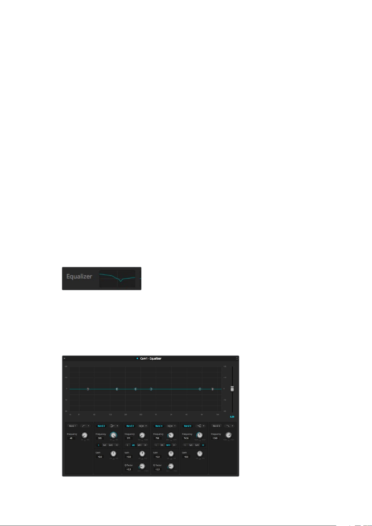
Parametric Equalizer
To open the parametric equalizer for an input or the master output, click on the corresponding
equalizer indicator.
Click on an input’s equalizer indicator to
open a 6 band parametric equalizer
The first item you will notice is the graph along the top of the window with numbered indicators
from 1 to 6. These numbered indicators are adjustable handles that correspond to bands 1 to 6.
Each band of the 6 band parametric equalizer has a column of settings. These settings will
differ based on which band you are controlling, and what filter type you are using.
Each audio input has its own 6 band parametric equalizer
26Using ATEM Software Control
Page 27
TIP You can learn more about band filters later in this section.
If you want to make changes to a setting, you will first need to make sure the band is enabled.
Click on a band label to enable it. When enabled, the button label is illuminated blue. Now you
can change the settings for that band, or click and drag the handles to make fast adjustments.
Handles
Each band handle is positioned along the line curve displayed in the graph. You can click and
drag each handle to choose the frequency you wish to adjust for that band, and the gain you
want to set. When moving a handle with your mouse, both the frequency and gain settings are
affected simultaneously, which gives you a fast way to make quick adjustments to each band
across the entire range of frequencies.
NOTE To make changes using a handle, ensure the band is enabled. Simply click on
the band you want to adjust. The band label will illuminate blue when enabled.
As you drag a handle left or right, you will notice the frequency and decibels update in the band
settings. This will also be reflected by the frequency range preset buttons for low, medium low,
medium high, and high.
Frequency Knobs
Alternatively, you can use the frequency knobs for each band to select a specific frequency
to adjust.
Range Presets
The frequency range for each band is defined by the range preset buttons. For example, low is
labeled ‘L’ and covers the frequency range from 30 to 395 Hz.
As a quick example of how the range presets define the frequency range, select a notch filter
from the band f ilter dropdown list, and then click on each range preset. You will see the filter
effect move to a position along the graph curve that corresponds to the range preset you
choose. This lets you quickly define aspecific range of frequencies you want the filter to affect.
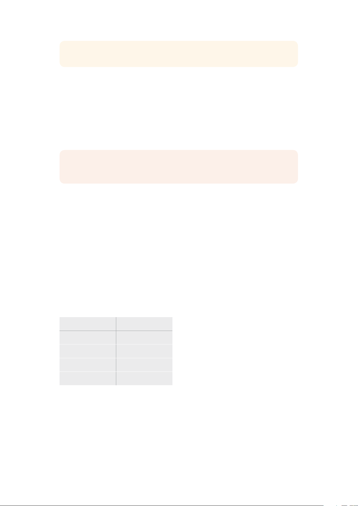
Below is a table showing the range of frequencies for each range preset setting.
Range Preset Frequency Range
Low 30 Hz to 395 Hz
Mid Low 100 Hz to 1.48 kHz
Mid High 450 Hz to 7.91 kHz
High 1.4 kHz to 21.7 kHz
Gain Knobs
Click and drag the gain knob left or right to decrease or increase the volume level for the
selected frequency.
27Using ATEM Software Control
Page 28
Q Factor
The Q factor control is available when the bell filter is applied to bands 2, 3, 4 and 5. This sets
the range of frequencies the filter will affect. For example, setting the minimum will allow the
filter to affect a wide range of surrounding frequencies and the maximum setting will narrow
theeffect down to a tiny point. This is important if you have sound qualities in surrounding
frequencies that you want to either include or exclude from the change you are making.
As you adjust the Q factor, watch the shape of the effect on the line curve change from a broad,
rounded edge to a sharp point. This is a visual representation showing how the regions of
frequencies surrounding the target frequency are affected.
TIP Compare the audio with changes against the original unaltered audio by clicking
on the bypass button at the very top of the equalizer window. This lets you turn the
equalizer on or off.
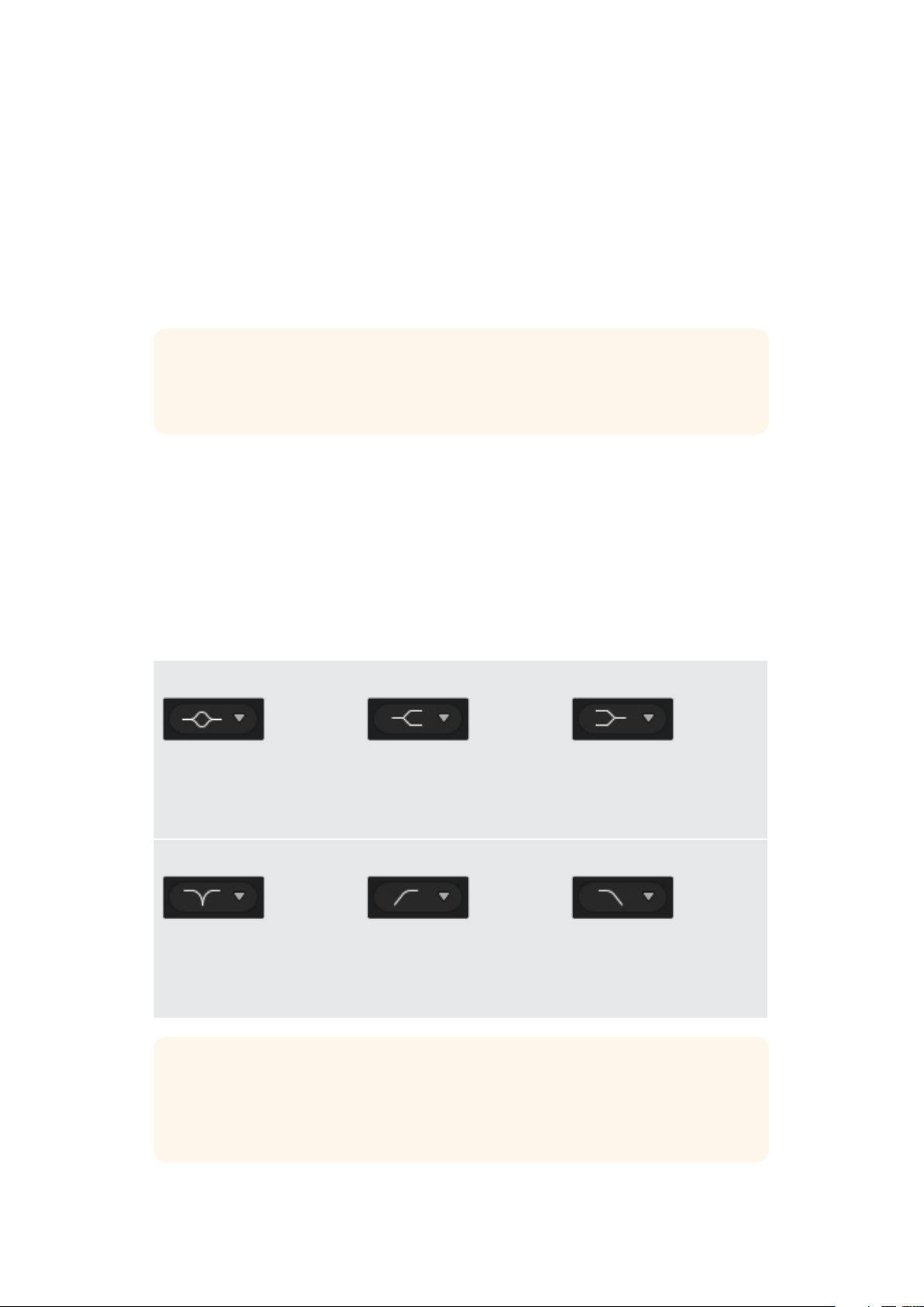
Band Filters
There are six different types of band filters you can choose from. These filters include bell,
high shelf, low shelf, notch, high pass, and low pass. These filters let you control specific
zones within the frequency range. For example, a low shelf filter lets you increase or decrease
the level of volume for lower frequencies on the graph, and a high shelf filter controls the
higher frequencies.
Try setting a low shelf filter to band 3 and make changes to the gain setting. You will see the
changes are weighted towards the low end frequencies on the graph.
A description for each filter type is provided below.
Bell High Shelf Low Shelf
This filter is used to increase
or decrease a range of
frequencies surrounding
adefined frequency.
Notch High Pass Low Pass
This filter lets you remove,
orcut, a defined frequency.
Lets you increase or decrease
the level of volume for higher
frequencies along the graph.
Smoothly removes extreme
low end frequencies, allowing
the high end frequencies to
pass unaffected.
Lets you increase or decrease
the level of volume for lower
frequencies along the graph.
Smoothly removes extreme
high end frequencies, allowing
the low end frequencies to
pass unaffected.
TIP It’s not uncommon to have filters on each band overlapping on the graph curve
with adjustments working together. For example, you may have a low shelf filter
applied to band 4, and a notch filter on band 5 reducing a frequency within the
same range.
28Using ATEM Software Control
Page 29
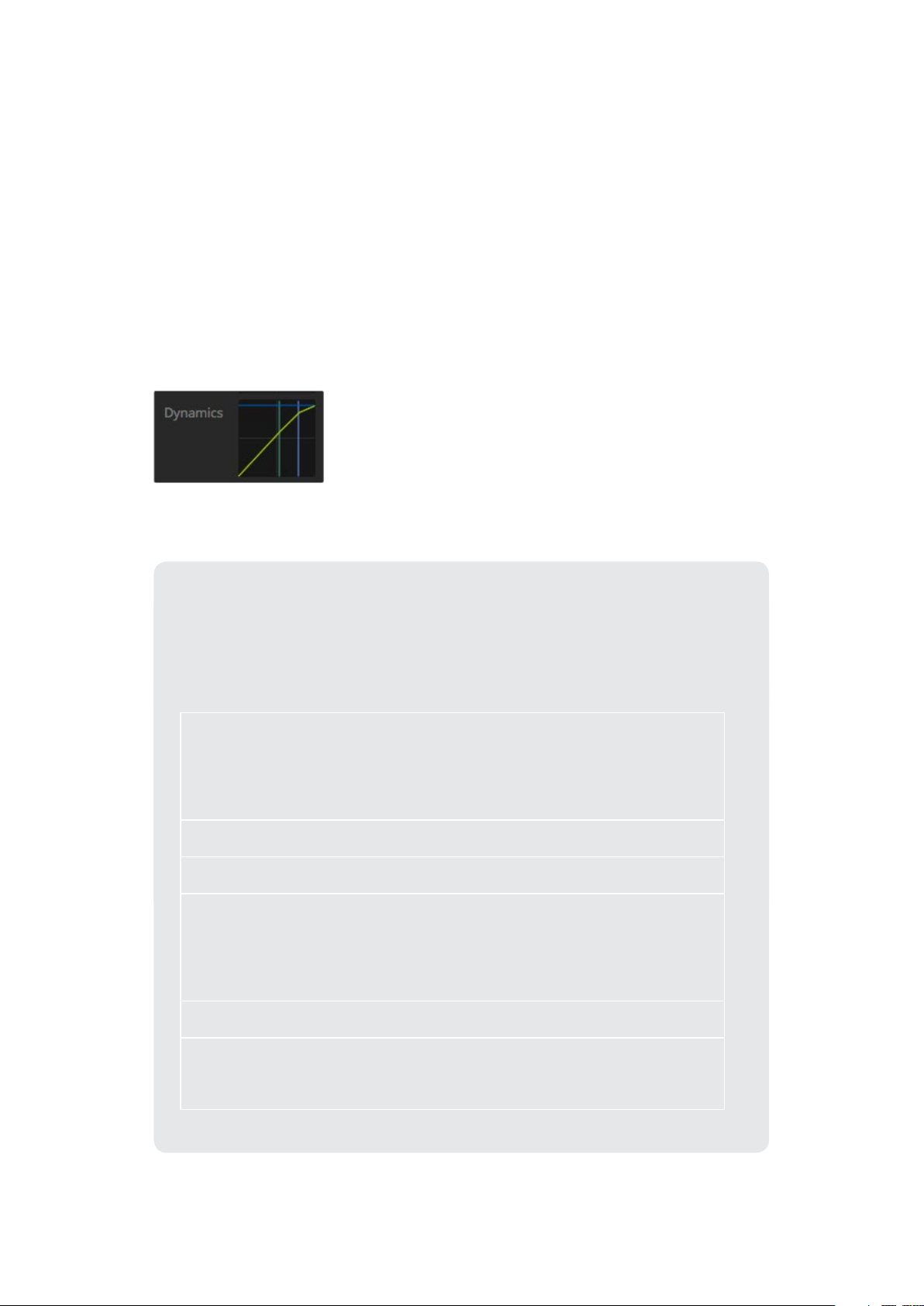
Dynamics Controls
In addition to the 6 band parametric equalizer, you can also enhance and finesse the input
andmaster output audio using dynamics controls. Where the equalizer lets you control the
frequencies within a signal, dynamics controls let you set how various levels behave. Levels
within the signal can be adjusted including expanding the dynamic range between low levels
and high levels, gating an input so you can choose what is stronger or softer within a signal,
oryou can even use the compressor and limiter so that audio can be generally lifted and made
stronger without clipping.
Combined with equalizer controls, these features are extremely powerful, giving you the ability
to precisely shape and define the audio and generally optimize the sound of the master output.
This section describes the expander, gate, compressor and limiter controls.
The dynamics controls can be opened for
each input and the master output by clicking
on its corresponding dynamics indicator
Common Dynamics Settings
The expander/gate, compressor and limiter share common settings that let you shape
how each function affects the audio. For example the level at which the function
initiates, how long the function is applied, the strength of the function, etc. The settings
available differ depending on the dynamics control you are using.
Threshold
Range
Ratio
Attack
Hold
Sets the sound level at which the function activates. For example, setting
the threshold for the compressor to -20dB tells your switcher to activate
compression when the signal rises above -20dB. Alternatively, setting the
expander to -40dB means the switcher will only initiate the expander once
the signal level drops below -40dB.
This setting defines the range of decibels affected by the function.
Defines the maximum strength of the function once initiated.
Sets the smoothness of the function when it initiates. For example, a long
attack will allow the function to fade into the signal, blending in better
without drawing too much attention, whereas a short attack may be better
for complex sound activity with many quick variations where a longer
attack may cause artifacts.
Sustains the dynamics function over an adjustable period of time.
Release
Similar to attack but occurs at the end of the function activit y. For example,
lets the dynamics function ease out gradually, or fall away rapidly, once the
level moves out of the threshold.
29Using ATEM Software Control
Page 30
Expander/Gate
The first set of dynamics parameters can be switched between expansion and gating.
Expansion emphasizes differences in volume by lowering the level of soft parts of the signal
relative to the level of louder parts. You can use an expander to emphasize the differences
between quiet and loud parts of a track, or to increase the dynamic range of a signal and
minimize unwanted noise.
Gating is like an exaggerated expander, reducing the level or even silencing parts of a signal
that fall below a certain level in order to reduce or eliminate noise in quiet parts of a recording.
For example, a range of 15 to 20 dB can reduce breathing in a vocal track but leaves just
enough to sound natural.
Gating is extremely effective, but it’s also very powerful so requires careful attention. If the gate
threshold is set too high it can cause artifacts, such as cutting off the start of a syllable or the
quiet end of a word. You can compensate by reducing the threshold slightly, or by increasing
the attack or release time.
Compressor
Compression lets you reduce peaks in an audio signal, reducing the dynamic range of a signal,
so you can boost the overall level without clipping. This is helpful when you want to make sure
the loud elements in a signal don’t diminish the strength of quieter sounds, or to smoothen
changes in audio levels within the signal.
TIP It’s a good idea to apply the compressor after you have set the EQ controls.
Make Up
The make up setting lets you increase the overall signal in combination with compression
settings. With loud parts of the audio reduced using compression, you can now use the make
up control to boost the overall sound without clipping.
Limiter
The limiter prevents peaks of the signal from exceeding a set maximum level. A limiter is helpful
to prevent hard clipping. For example, if you set the limiter to -8 dB, the input signal will never
exceed that level. Adjusting the attack, hold and release settings will set how gentle the limiter
affects the signal.
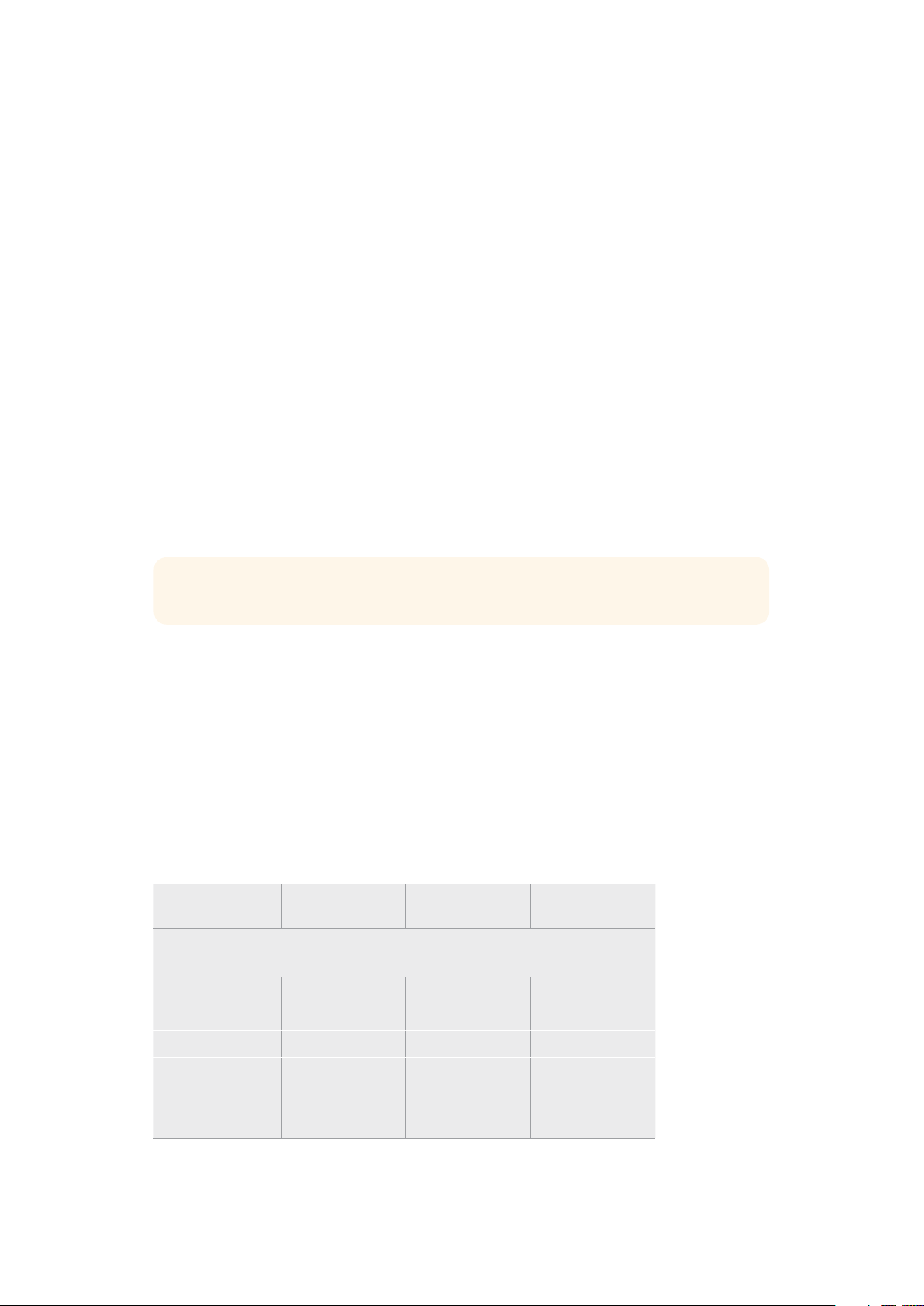
Dynamics Controls Characteristics
Control Minimum Default Maximum
Expander/Gate
Expander Controls*
Threshold -50dB -45dB** 0dB
Range 0dB 18dB 60dB
Ratio 1.0:1 1 .1:1 10:1
Attack 0.5ms 1.4ms 30ms
Hold 0.0ms 0.0ms 4s
Release 50ms 93ms 4s
30Using ATEM Software Control
Page 31

Control Minimum Default Maximum
Expander/Gate
Gate Controls*
Threshold -50dB -45dB** 0dB
Range 0dB 18dB 60dB
Attack 0.5ms 1.4ms 30ms
Hold 0.0ms 0.0ms 4s
Release 50ms 93ms 4s
Compressor
Compressor Controls
Threshold -50dB -35dB 0dB
Ratio 1.0:1 2.0:1 10:1
Attack 0.7ms 1.4ms 30ms
Hold 0.0ms 0.0ms 4s
Release 50ms 93ms 4s
Limiter
Limiter Controls
Threshold -50dB -12dB 0dB
Attack 0.7ms 0.7ms 30ms
Hold 0.0ms 0.0ms 4s
Release 50ms 93ms 4s
* Master Dynamics expander/gate controls are unused in Master Dynamics.
** Master Dynamics expander/gate threshold default is -35dB.
Mic Dynamics expander/gate threshold default is -45dB.
Fairlight Controls Workflow Guide
This section describes a basic workflow to help you get started using the Fairlight controls to
refine and enhance your audio mix.
1 Generally, the first step to optimizing your mix is to normalize all the inputs so they are
all at their maximum strength without clipping. This is normally done by increasing or
decreasing the input gain level for each input so their signal peaks just below 0dB on
the channel strip’s level indicator.
2 If you want to split any mono inputs into two separate channels for stereo output, go to
the general switcher settings and navigate to the audio tab. Enable the checkboxes for
the mono inputs you want to change to stereo. Click ‘done’.
TIP If you want to split mono inputs into two separate channels, it’s best to
do this before normalizing the input as described in step 1, so that you can
normalize both channels after they have been split.
31Using ATEM Software Control
Page 32

3 Now, click on the EQ indicators below input level controls and make equalization
changes to each input. You can move the windows into a better position, or close them
if needed.
4 After setting EQ, open the dynamics controls for each input by clicking on their
respective dynamics indicator. Make the required dynamics changes to generally
improve and refine the input audio.
5 With EQ and dynamics set for each input, you can now open the EQ controls for the
master output and sweeten the final audio mix.
6 Now open the master output’s dynamics controls and make any required changes to
improve the final output.
Once all the Fairlight controls are set, you can then increase or decrease the faders on the
audio mixer to set them at their best levels for the live mix and make adjustments where
necessary during the production. You can also go back to any of the settings and make further
adjustments if needed, but it’s best to follow the same order as described above to get the best
results from each function. For example, it’s important to set EQ controls before making
dynamics changes as the processing chain in your switcher applies dynamics to the audio
after equalization.
Most important of all is to apply the effects carefully so your audio still sounds natural but
exciting too!
Using the Media Page
The media page is where all your graphics or stills are stored and is very easy to use.
Simply find the still you want to use with the browse window, then drag and drop the file into
a slot in the media pool. From there, you can load any one of those stills into the media player
and switch it to air using the media player 1 source button on the software control panel.
You can also use stills in the media player with the upstream and downstream keyer.
Keep reading this section for information on how to use the media page in
ATEM Software Control.
32Using ATEM Software Control
Page 33

Navigating the Browse Window
The browse window is a simplified file browser that lets you navigate your computer to look for
graphics files. All attached drives on your computer are displayed, and you can select folders
from them. View sub folders by clicking on the arrows next to each folder.
The ‘preview’ window will show any selected graphics files.
Browse window
Browsing and loading files
Loading a still is as easy as dragging it from the browse window and dropping it into an empty
slot in the media pool.
When dropping a still into a slot, a progress indicator will show the loading status. You can
drop multiple files into the media pool, even if the first images have not yet completed loading,
as they will continue to load one after the other. If a still is dropped into a window which already
has content loaded, the existing content will be replaced.
The ATEM media pool supports PNG, TGA, BMP, GIF, JPEG and TIFF still image formats.
ATEM Media Pool
When files have been loaded into the media pool, the slots will show a thumbnail image.
Stills are marked with a slot number so you can identify them when assigning a still image to the
media player when using an external ATEM hardware panel.
33Using ATEM Software Control
Page 34

The file name for each loaded file is displayed underneath the slot so you can easily keep track
of files you have loaded. This is very useful as you will see a list of media pool still and clip
numbers and their file names in the media player palette on the switcher page.
Numbers are displayed on slots in the media pool to clearly show which slot is assigned to the
media player. When a media player slot is switched to the program output, the media player
number on the slot changes to red to indicate the slot is on air. When a slot is on the preview
output, the media player number changes to green.
ATEM Media Pool
On the switcher page, you can change the media player assignment from the media tab by
selecting your desired still from the ‘media’ dropdown list. Simply click on the arrow in the
player ‘media’ list to select from a list of media pool slots.
Image File Types
The ATEM media page can use many different file formats including TGA, PNG, BMP, GIF,
JPEG and TIFF.
Formats such as TGA include a separate ‘alpha’ channel together with the RGB color channels.
This lets you embed a matte, or key image, inside that alpha channel. When a TGA image is
loaded in the media player, ATEM Software Control will automatically detect the key image in
the alpha channel and load it as the linear key source. This means your TGA graphic will key
beautifully straight away with perfect transparency.
Creating a TGA File with an Alpha Channel
Below is a demonstration showing how to create a title in Photoshop with an alpha channel.
1 Launch Adobe Photoshop and start a new project. Set the project to use the same
horizontal and vertical dimensions used in your broadcast video format. For example,
if you are broadcasting 1080p50, set the resolution to 1920 x 1080 pixels.
2 In the layers panel, create a new layer and build the graphic you want to use. In this
demonstration, we are using a ‘wedding’ lower thirds graphic.
34Using ATEM Software Control
Page 35

3 Hold down the ‘command’ key on a Mac, or ‘control’ key for Windows, and click on the
layer thumbnail for your graphic. This will generate a selection of the color channels’
opacity values in your image. Their opacity determines the transparency of the graphic.
4 Go to the adjoining ‘channels’ panel and click on the ‘save selection as channel’ tool.
You will now see an alpha channel appear underneath the RGB color channels.
The alpha channel contains a greyscale version of the combined color channels
in your graphic. Don’t forget to click on the alpha channel’s ‘eye’ icon to make
sure it is selected so it will be included when the TGA file is saved.
35Using ATEM Software Control
Page 36

5 Your selection has now been used to create the greyscale matte in the alpha channel.
If you want to, you can now go to the ’menu’ bar and click ‘select/deselect’ to remove
the selection marquee.
6 Now it’s time to save your TGA file.
Go to the file menu and click on ‘save as’. Type the filename and select the location for
your file. In the format box, select ‘targa’, which is the full name for a TGA file and make
sure the ‘alpha channels’ checkbox is selected.
7 Click ‘save’. A targa options box will appear asking which resolution you want to save.
Select ’32 bits/pixel’. This provides enough data for four 8 bit channels which includes
the red, green and blue color channels, plus the alpha channel. Click ‘OK’.
)
Your TGA file is saved.
Now you can open ATEM Software Control and load the file into the media pool.
From there, drop the graphic into the media player and the alpha channel you saved
will automatically be loaded into the media player key source. The key source uses
the greyscale image in the alpha channel to tell the linear keyer transparency values
for the graphic.
If you switch the linear key to air, you will now see the graphic keyed over the
background with perfect transparency.
36Using ATEM Software Control
Page 37

Setting up Open Broadcaster
Open Broadcaster is an open source application that works as a streaming platform between
your ATEM Mini and your favorite streaming software like YouTube, Twitch, Facebook Live,
Vimeo Live and others. Open Broadcaster compresses your video to a bit rate that is easily
managed by your streaming app.
Below is a demonstration of how to set up Open Broadcaster to stream the webcam output
from your ATEM Mini using YouTube as the streaming application.
1 2
Launch Open Broadcaster and click on the plus
symbol in the ‘sources’ box.
Select ‘Video Capture Device’.
3 4
Name the new source and click ‘OK’. In the device drop down menu, select
Blackmagic Design and click ‘OK’.
5 6
Now go to your YouTube account. Navigate to the
‘video/live’ option and click ‘get started’.
In the YouTube ‘stream’ options, enter your
broadcast details and click ‘create stream’.
37Setting up Open Broadcaster
Page 38

7 8
YouTube will now generate a stream name/key
that will direct Open Broadcaster to your
YouTube account.
Click the ‘copy’ button nex t to the stream key.
Copy the stream key that you will now paste into
Open Broadcaster.
9 10
To connect Open Broadcaster’s broadcast link to
YouTube, click ‘start streaming’ in the bottom right
corner of the screen. This establishes the link to
YouTube from Open Broadcaster and from here
every thing will now be set using YouTube Live.
11 12
Return to Open Broadcaster and open the
preferences by clicking on ‘OBS/preferences’ in the
menu bar. Select ‘stream’. Now paste in the stream
key you copied from YouTube and click ‘OK’.
You will now see the video from your ATEM Mini in
the Open Broadcaster streaming preview window.
Go back to YouTube Live and you will see the
webcam program output from your ATEM Mini in
the background. Click ‘done’.
With Open Broadcaster now communicating with
YouTube Live, you are ready to begin your
broadcast. Now it’s time to perform your final
checks and make sure everything is good.
If you are all set, you can now begin your broadcast
by clicking ‘go live’.
You are now broadcasting live on YouTube with Open Broadcaster. When your broadcast is
finished and you have pressed the fade to black button on ATEM Mini, you can end the stream
by clicking ‘end stream’.
NOTE Due to the nature of internet streaming there can often be a delay, so it’s
important to watch the stream on YouTube and confirm your program has finished
before clicking ‘end stream’ to make sure you don’t accidentally cut the end of your
broadcast short.
38Setting up Open Broadcaster
Page 39

Using Adobe Photoshop with ATEM
Installing the ATEM software on your computer also installs a Photoshop plug-in that lets you
upload Photoshop graphics direct to the ATEM Mini’s media pool.
The plug-in connects to your computer via Ethernet the same way as any other computer
running ATEM Software Control on your network. For example, another operator can be
updating graphics live in Photoshop during your production and uploading them straight to
ATEM’s media player using the plug-in.
This means you can accept graphics from designers in the application that 100% of the world’s
designers use, Adobe Photoshop! You can even use the layers in a Photoshop image to keep
variations of graphics, such as different titles in a graphic, and then select the layers in
Photoshop you want, and then simply upload them at the press of a button. When uploading the
layers are automatically flattened in real time before upload. This happens in the background
and your document in Photoshop is unchanged by the export.
The ATEM export plug-in requires Adobe Photoshop CS5 or later. Install or reinstall the
ATEMsoftware after Photoshop is installed, to ensure the ATEM export plug-in is installed.
TIP If you are not streaming via ATEM Mini’s USB webcam output, but switching
content over the HDMI output instead, you can upload graphics from the Photoshop
plug-in via USB. However, due to the way USB establishes a connection to a single
client only, you will need to close ATEM Software Control so the Photoshop plugin can
access the USB connection, upload your graphics, then relaunch ATEM Software
Control to access the media pool.
ATEM export plug-in
Setting up Plug-in Switcher Location
The first time the Photoshop export plug-in is run, it will ask you to select your switcher location.
This is the IP address of the switcher so the plug-in can find the switcher to communicate with.
By default, the IP is set to 192.168.10.240, which is what the switcher IP address is originally set
to when first sold. If you want to export several versions of the same Photoshop f ile, you can
use the export plug-in window to name each exported file and also choose whether to set the
files to a media player after export.
39Using Adobe Photoshop with ATEM
Page 40

Preparing Graphics for Upload
For best results, you will want to use a Photoshop document resolution that matches the video
standard you’re using with your ATEM switcher. For 1080 HD you should use 1920 x 1080 pixels
in resolution. For 720p HD formats you should use 1280 x 720 pixels.
When working with Photoshop documents for ATEM, you should not put any content on the
background layer, but add all content to the layers above. The background layer should always
be plain full frame black, and you should use a pre multiplied key setting in the ATEM keyer for
keying graphics from Photoshop.
To help you get started, we’ve included a guide and some graphic template files in the Example
Graphics folder which was installed on your computer along with the ATEM Switchers software.
To upload the graphic to the ATEM media pool, simply select the export menu in Photoshop
and then select ATEM Switcher Media Pool to export. A window will appear asking you to
choose which position in the media pool you want to download to. The list includes all the file
names of graphics currently loaded in the media pool. Select which position you would like to
download to, and then select export.
If you’re in a hurry to get your graphics on air, then you can select to automatically copy this
graphic to the media player after download. This lets you get images to air fast! If you don’t want
to interfere with the media player graphic sources, simply select not to copy the media player to
this graphic.
Pre Multiply Alpha should almost always be enabled and requires that you also switch on the
Pre Multiplied Key setting in ATEM Software Control. Premultiplying mixes the graphic color with
its alpha channel when exporting to ensure your graphic has smooth edges which blend in to
the video.
Using Multiple Control Panels
When connected to a network via Ethernet, multiple computers can run ATEM Software Control
simultaneously, which means multiple operators can be dedicated to separate controls on your
ATEM Mini, for example media management and audio mixing.
40Using Multiple Control Panels
Page 41

ATEM switchers have multiple ways they can be controlled and you can use this software
control panel as well as a range of hardware control panels. In fact, if you connect your
ATEM Mini to a network that has other computers connected, you can run multiple copies of this
software control panel. This means you could have someone operating the switcher, while
someone else could be managing media or mixing audio. It’s quite flexible and this means
many people can be operating your ATEM Mini all at the same time!
A good example is the relationship between the software control panel, external
ATEM hardware control panel and the control panel of ATEM Mini. The software control panel
has been designed to be the same as the external ATEM hardware control panel. This is a
convention and well understood ME style of layout where you have a program row and preview
row of input controls and then a transition block that lets you command the transition.
If you plug in both control panels, you can see them mirror each other and any button pressed
on one control panel will be reflected on the other control panels instantly.
However, due to space limitations the control panel of ATEM Mini is a little bit different and it’s
interesting to see the relationship between how this control panel works and how the software
control panel works. A good way to understand this is to watch ATEM Mini’s panel control while
controlling the switcher via the software control panel.
Because of the limited space on ATEM Mini’s control panel, both the program and preview rows
have been combined together into a single row of buttons. When running ATEM Mini in program
preview switching mode, you can see the source selected on the program row because it’s
illuminated red and the source selected on the preview row because it’s selected green.
These are the same colors as the software control panel, but they are just on the same row of
physical buttons.
Using Macros
What is a Macro?
A macro is an easy way to automate a sequence of switcher actions so you can repeat the
sequence at the press, or click, of a button. For example, you can record a sequence of
transitions between several video sources, including key effects, audio mixer adjustments,
camera control settings and more. Record all your actions to a macro button, then when you
press that button all your recorded actions will be instantly performed. Macros are recorded
using the macros window in ATEM Software Control, and are stored inside your ATEM Mini.
You can run all your recorded macros using the software control panel.
The Macros Window in ATEM Software Control
To open the macros window in ATEM Software Control, click on macros in the title bar, or you
can also press shift/command/M for Mac, or shift/control/M for Windows. The macros window
is a floating window you can move freely about your desktop. This is so you can always access
the window when moving between the switcher, media, audio and camera pages. While
recording a macro, you can even reduce the size of the window by clicking on the minimize icon
at the top right corner.
Macros can be recorded to any of the 100 macro slots. Up to 20 macro slots are visible on
eachpage. Move forwards and backwards through pages by clicking on the arrows on the
bottom sides of the window. Clicking on the create and run buttons lets you swap between
the create and run pages so you can record your macros, and then run them during your
live production.
41Using Macros
Page 42

The macros window in
ATEM Software Control lets
you record and run macros
so you can easily repeat a
sequence of complex switcher
actions at the click of a button.
Recording Macros
Macros need to be recorded comprehensively, in clearly def ined sequences from start to finish
without error. This is because your macro will record every setting, press of a button, and
switcher action you perform. When you run a macro, all the switcher actions you recorded in
that macro will be repeated precisely.
It’s worth highlighting that a macro will only record the settings you change. For example, if you
want a 3:00 second transition, and your switcher’s transition rate is already set to 3:00 seconds,
you’ll need to change the duration, then set it back to 3:00 seconds to record the setting. If not,
your desired transition rate will not be recorded and when the macro is run it will simply use the
transition rate your switcher was last set to. So you can see why precision is important!
If settings are changed while recording a macro and you want them restored to a particular
state, simply restore those settings while recording the final steps of the macro. You can even
record macros to restore settings for various projects. You have lots of choices. The important
thing to remember when recording a macro is that you change all the settings you need to so
you can create the specific effects you want.
Recording a Macro using ATEM Software Control
In the example below, we’re going to create a macro that will set your ATEM switcher to perform
a 3 second mix transition from color bars to color 1, pause for 2 seconds, then perform a
3 second mix transition to black. Try building this macro on your ATEM switcher so you can
learn the steps in creating macros.
1 Launch ATEM Software Control and open the macros window.
2 Click on the create button in the macros window to select the create page.
3 Click on a macro slot you want to record your macro to. In this example, click on
macro slot 1. An orange border will appear around the slot you have selected.
42Using Macros
Page 43

4 Click on the create macro button, which is labeled with a ‘plus’ icon, to open the create
macro popup window.
If you want to, you can enter the name of your macro and type a description. This lets
you easily keep track of your macros and quickly see what each macro does. When you
click on a macro, your notes will appear in the status window.
To start recording a macro, select a macro
slot, then click on the createmacro but ton.
Type in your notes and click ‘record’.
5 Click the ‘record’ button.
The popup window will close and a red border will appear around your ATEM Software
Control panel indicating your macro is now recording. Notice the red ‘add pause’ button
at the top of the border.
Now that your macro is recording, you can start performing your switcher actions.
While recording, the create macro button
will change to a ‘record’ button. When you
have completed your switcher actions, click
on the ‘record’ button to stop recording.
6 Click on the bars button in the program panel on the switcher page. This sets bars to
your switcher’s program output.
7 Select color 1 on the preview output.
8 Open the transitions palette and set it to mix.
If mix is already selected, make sure your macro records the setting by selecting a
different transition type, for example the wipe transition, then clicking on mix again.
9 Now change the transition Rate to 3:00. This sets the mix transition duration to
3 seconds.
43Using Macros
Page 44

10 Click on the auto button in the transition style panel. Your switcher will perform a mix
transition from color bars to color 1.
11 To set the switcher to wait for 2 seconds before applying another transition, click on
the add pause button at the top of the red border. The ‘insert pause’ window will open.
Set the pause to 5 seconds and 00 frames and click ‘confirm’.
Why set a 5 second pause when you only want a 2 second pause? That’s because
when the mix transition occurs, it takes 3 seconds to complete. So if you want to add a
pause, you need to consider the transition duration, plus the pause you want to happen
before the next transition occurs.
In this example, it takes 3 seconds for the transition to complete, then 2 seconds for
your 2 second pause, so you should enter a pause of 5 seconds. Another way is to add
two separate pauses, one for the duration of the transition, and then another for the
pause you want. It’s up to you.
12 Now select black on the preview panel, and click the auto button in the transition style
panel. Your ATEM switcher will perform a mix transition to black.
13 Click the record icon in the macros window to stop recording your macro.
The macro you just recorded will now appear as a button in your selected macro slot.
To preview your macro, click the run button in the macros window to enter the run
page. Select recall and run, which sets the macros window to run a macro as soon as
you click on a macro button. Now click on your new macro button, named ‘Transitions’.
14 If you want your macro to instantly run as soon as you select it, click on the ‘recall and
run’ button. By enabling this feature you can load and play your macros with only one
click of a button.
If your macro was successful, you should see your ATEM switcher perform a mix from color bars
to color 1 using a 3 second transition, pause for 2 seconds, then perform another 3 second mix
transition to black, all by clicking one button in the macros window! Your ATEM switcher will also
display an orange border around your software control panel to indicate a macro is playing.
If your macro doesn’t perform the way you expect it to, simply rerecord the macro you just
created following the previous steps.
ATEM Software Control displays a red border to indicate when you are
recording a macro. The ‘add pause’ but ton located at the top of the red
border lets you enter durations for pauses between switcher actions.
44Using Macros
Page 45

Enter a name for your macro and a description so you can keep
track of the switcher actions recorded in the macro.
The image above shows how
a macro button appears in the
macros window after it has
been recorded. To run a macro,
click on the ‘run’ but ton to enter
the run page. Now you can
load and/or run the macro by
clicking on the macro button.
Building Large Macros
Macros can even include triggering other macros as part of recording a macro. This lets you
easily build larger macros from multiple smaller macros, i.e., recording macros with limited
actions, then compiling them into a large macro. This is because if there are any mistakes while
recording a large macro in one complete sequence, you’ll need to go back to the start of your
sequence and rerecord it. It’s a lot easier to work with segments containing a small number
of actions.
By recording a large macro using small macros, you can also edit your large macro by
rerecording only the small macros you want to change, then compiling your small macros back
into your large macro.
45Using Macros
Page 46

To compile small macros into a large macro:
1 Start recording a new macro, then while the macro is recording, click on the ‘run’
button to enter the run page.
2 Select ‘recall and run’ to automatically run macros at the push or click of a button,
or deselect to load a macro and play it manually.
3 Run your sequence of small macros, with pauses between each one to cover the
duration of each small macro, until you’ve completed the large macro.
4 Stop recording. You now have a complex, powerful large macro built from small macros
you can easily change later if you need to.
There is no limit to the amount of actions you can perform. You can easily build complex
transitions, create unique repeatable effects using keyers, or set up frequently used Blackmagic
Studio Camera settings, graphic overlays and DVEs so you don’t have to reconstruct them
every time you start a new program. Macros are fun and will save you a lot of time!
Macros Window Create Page
Create macro button:
Click this button to open the create
macro popup window. From here
you can name a new macro tobe
recorded, write a description of your
macro in the notes section, and click
record to start recording your macro.
Edit macro button:
First select the macro you
want to edit, then click
on the edit macro button
to edit the name and
description of the macro.
Delete macro button:
Select the macro you want
to delete, then click on the
delete macro button to
delete the selected macro.
Macro buttons:
After recording a macro
to a selected macro slot,
your macro will appear as
a macro button. 20macro
buttons can be displayed
on one page. If a macro is
unnamed when recording,
the number of the selected
macro slot will be used.
Status window:
This window provides helpful prompts
and status messages to help you
getstarted recording and running your
macros. When a macro is selected, it also
displays any notes you have included.
Arrow buttons and page Icons:
To access or record more than 20macros, simply click on the
right arrow at the bottom corner of the macros window to open
a new page of macros. Tomove to the previous page of macros,
click on the left arrow. You can see which page of macros you
are viewing by observing the page icons between the arrows.
46Using Macros
Page 47

Macros Window Run Page
Recall and Run:
Selecting the Recall and Run feature lets
you instantly run a macro by clicking a
macro button. Deselecting the Recall
and Run feature lets you load a macro
by clicking on your macro button. Run
the macro by clicking the play button.
Play:
When Recall and Run
is deselected and you
have loaded a macro by
clicking on a macro button,
click the play icon to start
playing the macro.
Stop:
Clicking the stop button
will stop the playback of a
macro, but will complete
the current action first. For
example, if you press stop
half way into a transition,
the switcher will finish the
transition and then stop.
Loop:
When the loop button is
selected and you run a
macro, your macro will
run continuously until
you click the stop button.
When loop is deselected,
your macro will run
until it is completed.
Changing Switcher Settings
Clicking on the switcher settings ‘gear’ icon will open the settings window where you can
change general switcher settings, label, HyperDeck and remote settings. These settings are
divided into tabs.
Changing switcher settings
47Changing Switcher Settings
Page 48
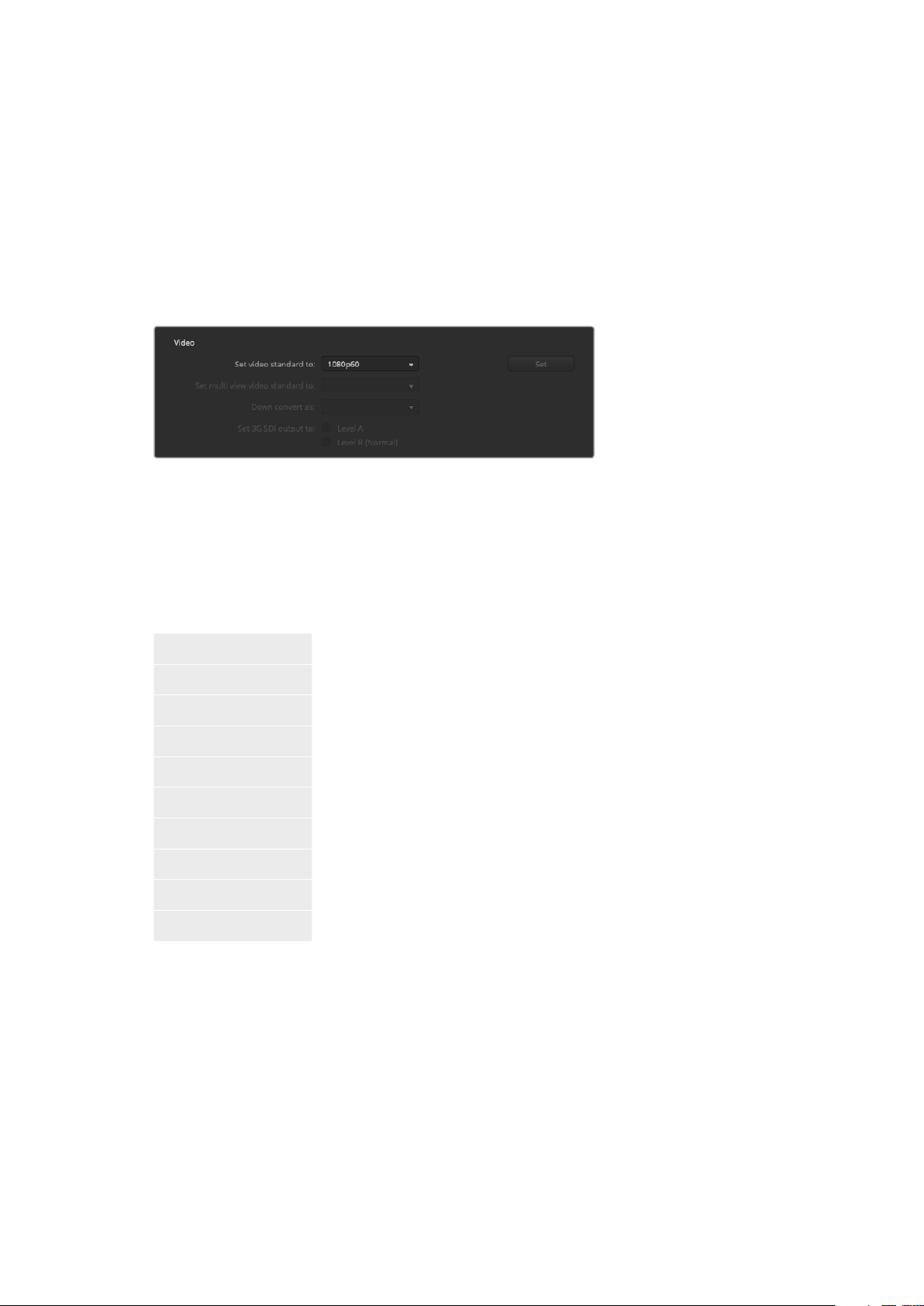
General Settings
Setting the Switcher Video Standard
The video setting is used to select the operating video standard of your ATEM Mini. The video
standard is set automatically when you plug in the first HDMI source, however if you ever need
to change the video standard you can use this setting to do that. All video sources will then be
converted to match the set video standard.
If you want to return ATEM Mini to automatically detect the first connected video format, select
‘auto mo de’.
Set video standard
ATEM Mini Supported Video Standards
To set the video standard, select the format you want to use from the ‘set video standard to’
drop down menu, and then click on the set button. Any time the video standard is changed, the
switcher will remove any stills you have loaded into the media pool, so it’s best to set the video
standard before loading any media.
1080p59.94
1080p50
1080p29.97
1080p25
1080p24
1080p23.98
1080i59.94
1080i50
720p59.94
720p50
Setting Audio Input and Output Behaviour
The ‘audio’ tab lets you control the nature of the audio follow video feature plus set the mic
inputs to mic or line level audio. Microphones typically have weaker signals compared to line
outputs from other audio devices. This means when mic is selected, the input is boosted
slightly to compensate. This also means that if mic is accidentally selected when a line level
input is plugged in, the audio will sound unusually loud. If the audio sounds much louder than it
should be, check that line is selected instead of mic.
48Changing Switcher Settings
Page 49
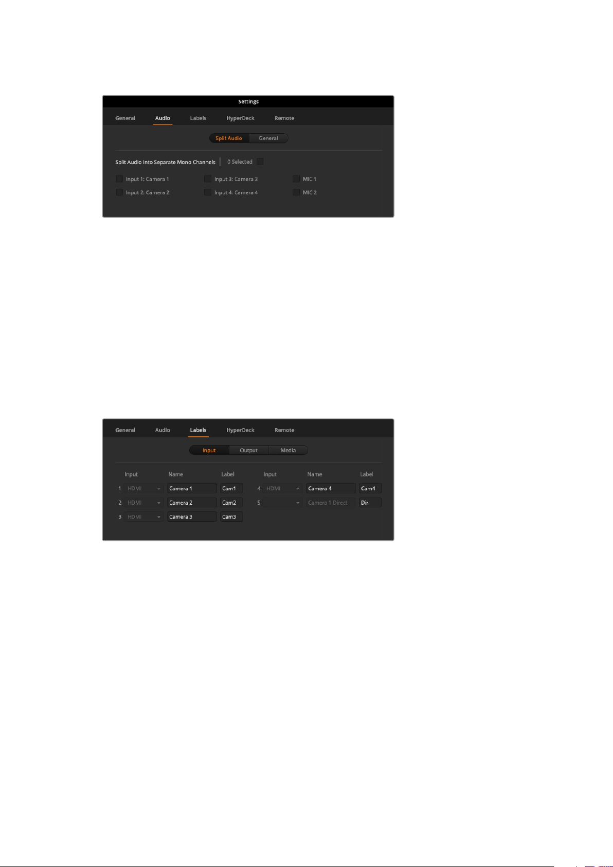
Audio Follow Video Behaviour
You can change the nature of the audio follow video feature for when switching sources.
For example, select ‘hard cut audio when switching’ to allow the the audio from an input to
switch immediately to another. If you want to the audio to smoothly transition over a brief period
of time, select ‘add a transition to audio when switching’.
Split Audio
Split a mono input signal into two separate mono channels. This is helpful for mixing a mono
input into both channels on the stereo master output. You can also add a stereo simulation
effect using the advanced Fairlight controls on theaudio page.
Click on the desired input checkbox to split the channels for that input.
Labels Settings
Label settings
The input labels settings let you customize the name of each input using a long and short name.
The short name will appear on the switcher input buttons on the software panel. If you are using
an additional ATEM broadcast panel, the long and short labels allow for the short label to fit into
the broadcast panel’s smaller display. The short 4 character name is used to identify the video
input on the source names display. The longer input names support up to 20 characters and are
displayed in various dropdown source selection boxes on the software control panel.
To change an input name, click in the text field, enter the text and click ‘save’. The input name
will be updated on the software control panel and external hardware panel if one is connected.
It’s a very good idea to change both the short and long labels at the same time, so they match.
For example Camera 1 would be entered in as a long label, and CAM1 as the short label.
49Changing Switcher Settings
Page 50
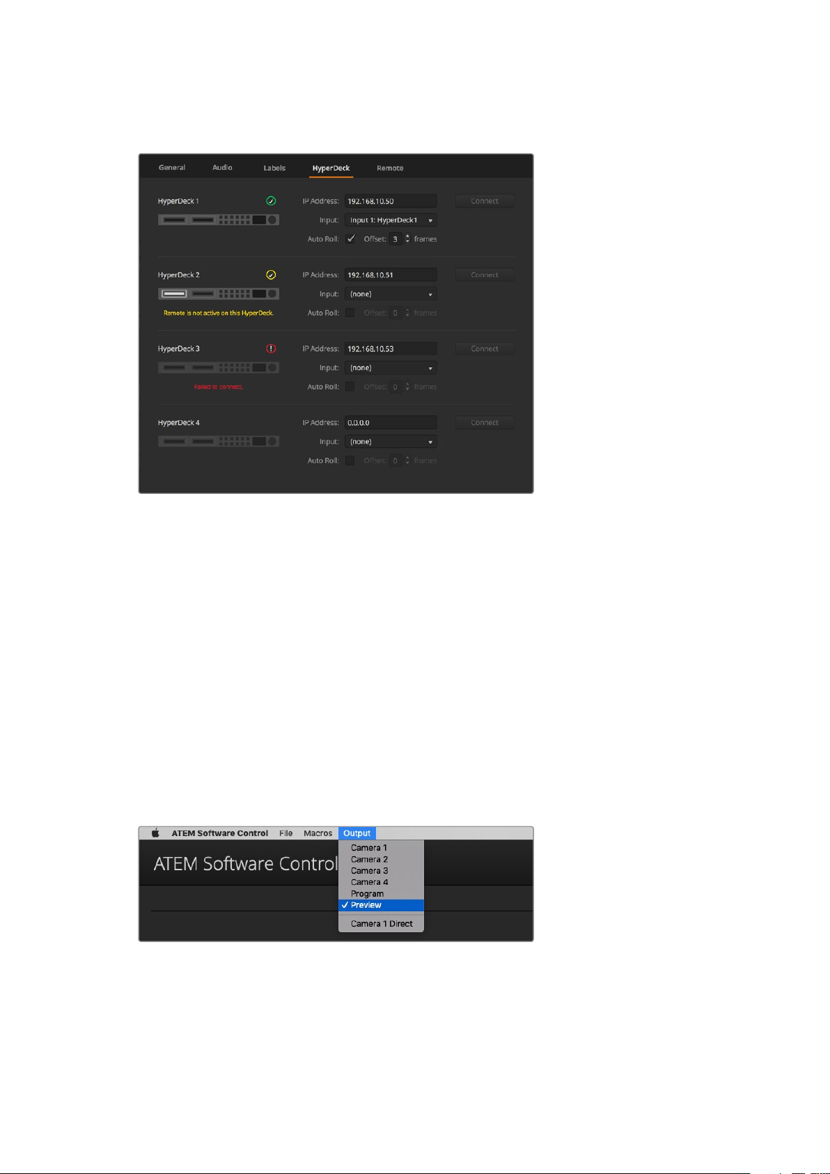
HyperDeck Settings
HyperDeck settings
You can connect up to 4 Blackmagic HyperDeck Studio disk recorders to a network via
Ethernet and control them using ATEM Software Control. When connecting HyperDecks, use
these settings to configure the IPAddress, select the inputs your HyperDecks are connected
to, turn the auto roll feature for each deck on or off, and set their frame offset settings so they
can switch cleanly.
Status indicators appear above and below each deck so you can easily see if they are
successfully connected and if their remote buttons are active.
For detailed information on setting up Blackmagic HyperDecks with your ATEM switcher and
setting the ‘HyperDeck’ configuration settings, refer to the ‘HyperDeck control’ section of
this manual.
Setting the HDMI Output Source
The HDMI output can have various sources routed to it. For example all video inputs, program,
preview, plus camera 1 direct for a low latency loop output when gaming.
HDMI output control menu on Mac OS
50Changing Switcher Settings
Page 51

To set the HDMI output, simply click on the ‘output’ option in the menu bar, then scroll the list
for the source you want to output. When selected, the HDMI output will change immediately.
You can see the current source with a tick in the menu item.
Program/Preview and A/B Direct Transition Control
When you first receive your ATEM switcher, it will be set to program/preview switching which is
the current standard for mix/effects switchers. You can change this preference to A/B Direct if
you wish to use legacy A/B switching. You’ll find the ‘transition control’ options in the
preferences window of ATEM Software Control.
Saving and Restoring Switcher Settings
ATEM Software Control lets you save and restore specific settings, or all of the switcher settings
you have created. This powerful feature is incredibly time saving on live productions where
regular settings are used. For example, you can immediately restore saved picture in picture
settings, lower third graphics and detailed key setups from a laptop or USB drive.
Saving settings menu.
Saving your Settings
1 Go to the menu bar in ATEM Software Control and select File>Save As.
2 A window will open asking for a file name and destination folder. After you have made
your selection, click Save.
3 You’ll now see the Save Switcher State panel containing checkboxes for all the
available settings on each block of your ATEM switcher. The Select All checkbox is
enabled by default. If you save with Select All enabled, ATEM Software Control saves
your entire switcher settings. If you want to choose specific settings to save, you can
deselect settings individually, or to remove all settings click Select All once to deselect
them. Now you can select specific settings you want to save.
4 Click Save.
ATEM Software Control saves your settings as an XML file together with a folder for
ATEM media pool contents.
51Changing Switcher Settings
Page 52

With ATEM Software Control you can save and restore all your switcher settings for your
liveproduction, including key set tings, transition styles, media pool contents and more
After you have saved your settings you can quick save at any time by selecting File>Save, or by
pressing Command S for Mac, or Ctrl S for Windows. Doing so will not overwrite your previous
save, but will add a new XML file to your destination folder which is clearly identified with a time
and date stamp. This means you can always restore a previous save if necessary.
Restoring your Settings
1 Go to the menu bar in ATEM Software Control and select File>Restore.
2 A window will ask for the file you want to open. Select your save file and click Open.
3 You’ll now see a window containing active checkboxes for your saved settings on
each block of your ATEM switcher. Leave Select All enabled to restore all your saved
settings, or select only the checkboxes for the settings you want to restore.
4 Click Restore.
If your switcher settings are saved on a laptop, it’s easy to take all your settings with you on
location. Connect your laptop to any ATEM switcher and quickly restore your switcher settings.
Live production can be a busy and exciting time and you’re always working in the moment,
which means you can easily forget to back up your saved files when the production is over.
Ifyou have settings you want to keep, save them to your computer and an external drive,
such as a USB drive. This means you can carry your settings with you and have a back up in
case your settings are accidentally deleted on your computer.
52Changing Switcher Settings
Page 53

Saving your Startup State
If you have your switcher set up the way you want it, you can easily save your entire switcher
state as your default startup state. Go to the ‘file’ menu in ATEM Software Control and select
‘save startup state’. Now whenever you restart your switcher, it will start up with your saved
settings by default. If you want to clear the startup state and revert to the factory settings on
restart, go to the ‘file’ menu and select ‘clear startup state’.
Saving your switcher settings on a laptop gives you the portability
to restore your settings on any ATEM switcher. Saving to a
USBdrive means you can even carry your settings in your pocket.
Preference Settings
The preferences settings are arranged as ‘general’ preferences and ‘mapping’ preferences.
Thegeneral preferences contain network settings, transition control and language
selection options.
General Preferences
ATEM Software Control can be set to display in English, German, Spanish, French, Italian,
Japanese, Korean, Portuguese, Russian, Turkish and simplified Chinese languages.
When running ATEM Software Control for the f irst time after installation, a setup dialog box will
prompt you to set the language for the software, but you can change the language of the
software at any time.
To change the language:
1 Go to the menu bar at the top of your screen, select ‘ATEM Software Control’ and open
the ‘preferences’.
2 Select your desired language from the drop down menu in the ‘Software Control
Language’ in general settings.
A warning will appear asking you to confirm the action. Click ‘change’.
ATEM Software control will now close and restart in your selected language.
53Changing Switcher Settings
Page 54
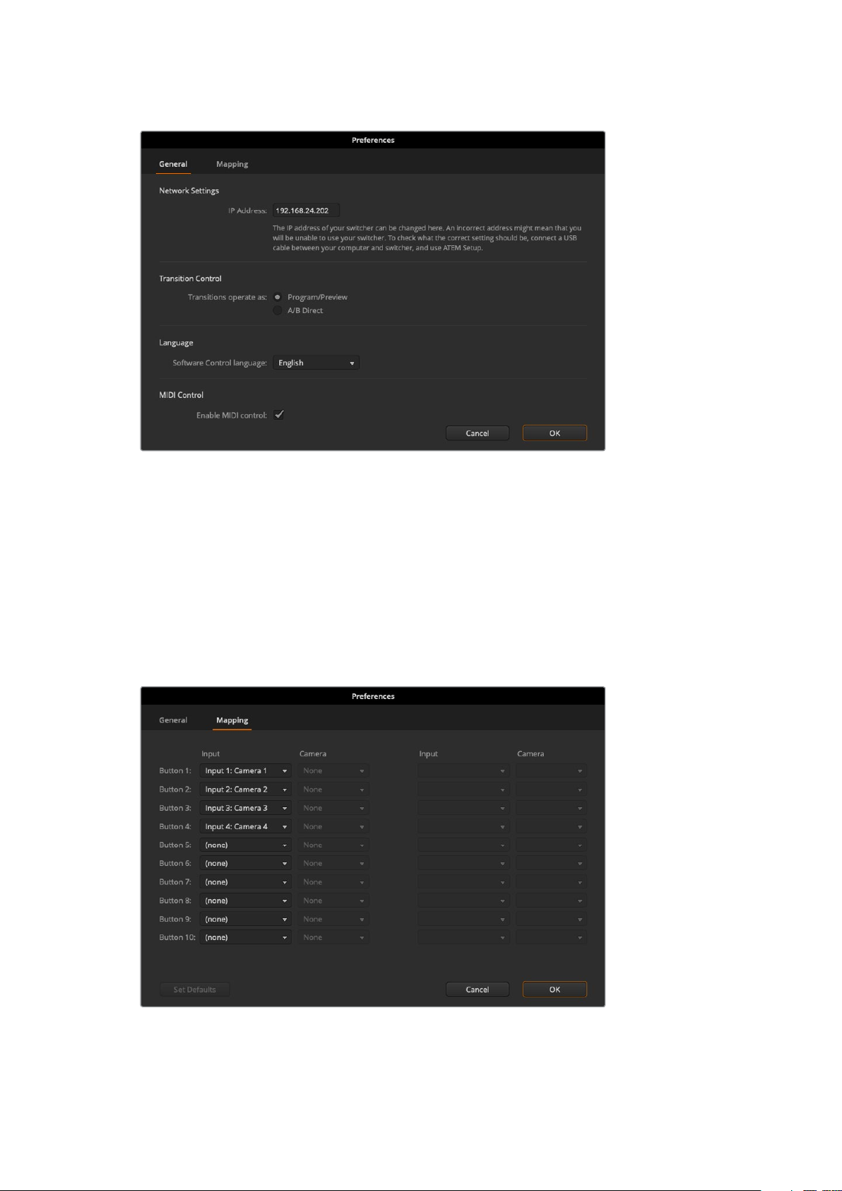
You can change the language for ATEM Software
Control in the ATEM Software Control preferences.
Button Mapping
In the mapping preferences, you can assign inputs to specific buttons on the preview and
program rows.
ATEM Software Control and external ATEM hardware panels support button mapping so you
can assign sources to different buttons. For example, occasional sources can be assigned to
less prominent buttons. Button mapping is set independently for each control panel so button
mapping set on a software control panel will not affect the button mapping set on a hardware
control panel.
You can assign important cameras to more prominent buttons
54Changing Switcher Settings
Page 55

Using Keyboard Hot Keys
Hot keys can be used allowing convenient control of some switcher functions using a standard
QWERTY keyboard as shown in the following table:
Hot Keys Function
<1> - <0> Previews source on switcher Inputs 1 - 10. 0 = input 10.
<Shif t> <1> - <0> Previews source on switcher Inputs 11 - 20. Shif t 0 = input 20.
<Control> <1> - <0> Hot switches source on switcher Inputs 1 - 10 to Program output
Press and release <Control>,
then <1> - <0>
<Control> <Shift> <1> - <0> Hot switches source on switcher Inputs 11 - 20 to Program output
Press and release <Control>,
then <Shift> <1> - <0>
<Control> Turns off hot switching if currently on. The CUT button is lit white.
<Space> CUT
<Return> or <Enter> AUTO
Hot switches source on switcher Inputs 1 - 10 to Program output.
Hot switching remains on and the CUT button is lit red.
Hot switches source on switcher Inputs 11 - 20 to Program output.
Hot switching remains on and the CUT button is lit red.
ATEM Mini Setup Settings
When ATEM Software Control is installed on your computer, a setup utility called ATEM Setup
will also be installed. This setup utility lets you update your ATEM Mini, name the unit, change
network settings and provides panel settings including program preview and cut bus switching
modes, plus keyer related switching settings.
TIP For information on how to change network settings, refer to the
‘connecting to a network’ section.
55ATEM Mini Setup Settings
Page 56

Updating your ATEM Mini
To update your ATEM Mini, simply connect the unit to your computer via USB or Ethernet.
Launch ATEM Setup. If the software version installed on your computer is newer than the
version installed on your ATEM Mini, a dialogue box will appear notifying you of an update.
Simply click on the ‘update’ button and follow the prompts to update the unit.
A progress bar will appear with a notification to let you know when the update is complete.
Configure Page
Panel Settings
Switching Mode
This setting lets you set ATEM Mini to use program preview or cut bus switching modes. Refer
to the ‘Switching Modes’ section for more information.
Picture in Picture Keyer
This setting lets you choose to keep the picture in picture on screen indefinitely so you can
switch content underneath it, or tie it to the next transition so when you perform the transition,
picture in picture will transition off screen with it.
ͽ Drop with Transition
Ties picture in picture to the next transition and will transition off screen when the next
transition is performed.
ͽ Stay on with transition
Holds picture in picture on air so you can switch sources without affecting picture
in picture.
TIP Drop with transition lets you smoothly turn off picture in picture by linking it
with the transition, however you can always turn picture in picture off at any time
by pressing the respective off button on the control panel.
Chroma Keyer
These settings are similar to the picture in picture keyer setting, however it applies to the
upstream keyer.
ͽ Drop with Transition
Ties the upstream chroma keyer to the next transition and will transition off screen
when the next transition is performed.
ͽ Stay on with transition
Holds the upstream chroma keyer on air so you can switch sources without affecting
the chroma key.
About Page
The about page tells you which version of ATEM software is installed on your computer.
To change the name of your ATEM Mini, click in the ‘label’ edit box, type in a new name and
click ‘save’
56ATEM Mini Setup Settings
Page 57

Expanding your ATEM Workflow
ATEM Mini is designed to be controlled using its own built in control panel, but if you have a
larger production that is more complex and have many sources, graphics and intricate keys to
handle, or you need to operate your ATEM Mini from a separate location, an external
ATEM hardware panel will help you.
Using an External ATEM Hardware Panel
External ATEM hardware panels, such as the ATEM 1 M/E Advanced Panel, can be used to
control your ATEM Mini remotely. You have the option to build your workflow to suit any project.
External ATEM hardware panels connect to your ATEM Mini via Ethernet and are programmed
with a default switcher IP address that works with your ATEM Mini, so once plugged in, the
panel will instantly recognize ATEM Mini and you can then switch sources and control your
ATEM Mini via the external panel.
Connecting to a Network
If you want to connect your ATEM Mini to a larger Ethernet network, then you will most likely
need to change the network settings on your ATEM Mini. Most people simply plug their
computer and control panel direct to the switcher, however in some situations it can be very
powerful to connect via your network!
Your ATEM Mini ships from the factory with settings to allow hardware control panels to simply
be connected directly with an Ethernet cable. However your ATEM supports full Ethernet
IP protocols so you can place your ATEM Mini and external control panel on your network or
anywhere on the planet using the internet. Connecting to a network means you have enormous
flexibility with how you control your switcher. For example, you can connect an
ATEM 1 M/E Advanced Panel on the same network to ATEM Mini and have two operators
switching content. In addition, you also have the software panel on your computer so you can
even have a third operator handling audio, or managing media from the software panel.
57Connecting to a Network
Page 58

However, it’s worth noting that if you use your ATEM Mini on a network, then you’re also
increasing the complexity of the connection between your control panel and the switcher,
so there is possibly a greater chance of something going wrong. ATEM Mini can also be used
when plugged into a switch, and even via most VPNs and over the internet.
Connec t ATEM Mini to a network and then you can operate your switcher using
ATEM Software Control on any computer connected to the same network
Understanding Network Settings
For all devices to communicate, they must share the same subnet mask and gateway settings.
In addition, the first three fields of numbers in the panel’s IP address also need to match.
For example, ATEM Mini’s default IP address is 192.168.10.240 and an external ATEM 1 M/E
Advanced Panel’s default IP address is factory set to 192.168.10.60. This means all units share
the first three fields of numbers, but have their own identifying number in the last field so they
won’t conflict with each other.
This is generally the most important principle to know when working via Ethernet. When
connecting to a network, these settings will likely need to be changed. This section of the
manual will describe how to do that.
Connecting Locally via Ethernet
When ATEM Mini is connected directly to ATEM 1 M/E Advanced Panel, the default IP addresses
on each unit will ensure they work automatically.
Below is an example of network settings when ATEM Mini is connected directly to
ATEM 1 M/E Advanced Panel.
ATEM Mini IP Settings
IP Address - 192.168.10.240
Subnet Mask - 255.255.255.0
Gateway - 192.168.10.1
ATEM 1 M/E Advanced Panel Panel IP Settings
IP Address - 192.168.10.60
Subnet Mask - 255.255.255.0
Gateway - 192.168.10.1
Notice that all the numbers are the same except for the last field of each IP address. This means
they are set correctly and the units will communicate with each other without conflicts.
58Connecting to a Network
Page 59

Connecting to a Network
When connecting to a network, the network will have its own subnet mask, gateway, and IP
address settings which every connected device will conform to. When connecting to a network,
you will need to make sure both your ATEM Mini and the ATEM 1 M/E Advanced Panel share
those numbers and similarly with regards to the IP address, have their own identifying number
in the last f ield so they won’t conflict with each other.
Below is an example showing ATEM Mini and an ATEM 1 M/E Advanced Panel set to conform to
a network:
Network IP Settings
IP Address - 192.168.26.30
Subnet Mask - 255.255.255.0
Gateway - 192.168.26.250
ATEM Mini IP Settings
IP Address - 192.168.26.35
Subnet Mask - 255.255.255.0
Gateway - 192.168.26.250
ATEM External Hardware Panel IP Settings
IP Address - 192.168.26.40
Subnet Mask - 255.255.255.0
Gateway - 192.168.26.250
If there are other devices on the network that have the same identifying number in their IP
address, there will be a conflict and the units won’t connect. If you encounter a conflict, simply
change the identifying number in the unit’s IP address. Refer to the next sections for information
on how to change network settings.
NOTE If ATEM 1 M/E Advanced Panel is not connecting to your ATEM Mini and
displays a message saying it is looking for the switcher, you will need to tell the panel
where your switcher is on the network. This is simply typing your ATEM Mini’s
IP address into the panel’s switcher IP settings. Refer to the next sections for
information on how to set the switcher IP location on ATEM 1 M/E Advanced Panel.
Changing ATEM Mini’s Network Settings
ATEM Mini’s network settings are changed using Blackmagic ATEM Setup via USB.
Please follow the steps below:
To change the network settings via Blackmagic ATEM Setup:
1 Connect ATEM Mini via USB to the computer running the setup utility software.
2 Launch Blackmagic ATEM Setup and select your ATEM Mini.
3 ATEM Mini’s current IP address, subnet mask and gateway settings will be displayed in
‘configure’ window. If you only want to check the IP address and not change it, youcan
simply quit the setup utility by clicking ‘cancel’.
4 To change the IP address or any other settings, simply edit the numbers and then
click ‘save’.
59Connecting to a Network
Page 60

Change network settings using the ‘configure’ tab in Blackmagic ATEM Setup.
Setting the Switcher IP Location
To set ATEM Mini’s IP location on ATEM 1 M/E Advanced Panel so the panel can find ATEM Mini
and communicate, simply follow these steps:
Changing the Switcher’s IP location on ATEM 1 M/E Advanced Panel
1 When there is no communication with tATEM Mini, the LCD will say ‘connecting’
andnotify you of the IP address it is searching for. If the panel can’t find the switcher,
the connection will time out and a notification will ask you to check the IP address.
Pressthe ‘network’ soft button above the LCD to open the network settings.
2 In the network settings, press the right arrow in the system control buttons next to the
LCD to move to the ‘switcher IP address’ setting.
3 Now use the corresponding LCD soft control knobs to set the correct IP address for
your switcher.
4 Press the ‘save changes’ soft button to confirm the setting.
Your panel will now connect with your switcher.
On the ATEM 1 M/E Advanced Panel, press the ‘network’ LCD sof t button to open
the network set tings on the LCD, then use the system control arrow buttons
to navigate to the switcher IP address setting. Use the soft controls to set the
network IP address for your switcher, and don’t forget to save the changes.
60Connecting to a Network
Page 61

NOTE Changing the switcher IP address on your panel does not change the
IP address of ATEM Mini itself. It just changes where the control panel is looking to find
the switcher.
Setting DHCP or Fixed IP Addresses
External ATEM hardware control panels can be set to DHCP or fixed IP addresses. Generally
when used on a network, the control panel should be selected to DHCP, which means it is
automatically assigned an IP address when connected to the network.
NOTE ATEM Mini always needs a fixed IP address so the external control panel has a
stable IP location to connect to.
Changing the Hardware Panel Network Settings
Because the hardware panel is also on the network and communicating with the switcher,
it also has network settings so it can connect to the network. These settings are different to the
switcher IP address, which is just where the panel is looking to find the switcher. The panel
network settings can be changed by following the steps below:
Changing Network Settings on ATEM 1 M/E Advanced Panel
Change network settings using the system
control buttons and LCD soft controls
1 Press the ‘home’ button in the system control buttons to open the LCD home menu.
2 In the home menu, press the ‘network’ soft button to open the network settings.
3 The next step is to decide if you want the panel to use a fixed IP address or to be
automatically assigned an IP address from a DHCP server. Set DHCP on or off by
pressing the corresponding DHCP ON/OFF soft button.
61Connecting to a Network
Page 62

NOTE If you’re connecting direct to a switcher without a network, then you
won’t have a DHCP server to assign an IP address automatically, so you will
want to select ‘DHCP off’. ATEM 1 M/E Advanced Panel is delivered with a
fixed IP address set to 192.168.10.60 for a direct connection.
However, if your network has lots of computers that automatically assign
IP addresses via DHCP, then you can also select ‘DHCP on’ so the panel can
get its network information automatically. This is possible on the panel, and it’s
only the switcher itself that always requires a fixed IP, as the switcher needs to
be found by the control panels at a known fixed address on your network.
If you select ‘DHCP on’, your network settings will be complete because the
panel network settings will be obtained from the network automatically.
4 If you have elected to use a fixed IP address, you now need to set this IP address by
adjusting the corresponding soft control knobs for each field of the IP address.
You can also use the numeric keypad. Changing this IP address may cause the panel
to lose communication.
5 If the subnet mask and gateway address need to be set, then press the right arrow
button in the system control buttons to progress through each setting menu, and use
the knobs or the numeric keypad to edit. If at any time you want to cancel the changes,
press ‘undo’.
6 When you are happy with your settings, press the ‘save changes’ soft button to confirm.
When you are happy with your network settings,
press the ‘save changes’ button to conf irm them
ATEM Software Control via the Network
Lastly, if you want to use ATEM Software Control as well as an external ATEM hardware panel,
you need to ensure your computer is connected and working on your network. Once launched,
if ATEM Software Control cannot communicate with ATEM Mini, you will be prompted
automatically to enter ATEM Mini’s IP address. Once you have set the address, ATEM Software
Control can find your switcher and communicate.
62Connecting to a Network
Page 63

Multiple computers can run ATEM Software Control simultaneously, which means multiple operators can
be dedicated to separate controls on your switcher, for example media management and audio mixing.
Using External ATEM Hardware Panels
When using an external hardware panel and the software panel together, any change on one
panel will be reflected on the other, and you can use both panels at the same time.
This section shows how to use ATEM 1 M/E Advanced Panel should you need an external
hardware panel for your live production.
ATEM 1 M/E Advanced Panel
The ATEM 1 M/E Advanced Panel is designed for switchers with one mix effects panel.
The control panel provides high quality buttons for fast, comprehensive control over your
switcher, plus advanced CCU control and the ability to control up to 4 M/Es from the one panel.
System control is fast and convenient using a centralized LCD menu with soft buttons
and controls.
63Using External ATEM Hardware Panels
Page 64

Using the ATEM 1 M/E Advanced Panel
ATEM 1 M/E Advanced Panel
Using the Control Panel
Mix Effects
The program bus, preview bus and source names display are used together to switch sources
on the program and preview outputs.
ATEM Mix Effects
Source Name Displays
The source name displays use labels to represent the switcher’s external inputs or internal
sources. Labels for the external inputs can be edited on the settings window of the software
control panel. Labels for the internal sources are fixed and don’t need to be changed.
The displays show the labels for each row of buttons in the source select row, program row, and
preview row.
Pressing the SHIFT button will change the source names display to show extra sources, called
shifted sources, allowing selection of up to 20 different sources.
Simultaneously pressing both SHIFT buttons next to the source select and program rows will
change the source names display to show protected sources, and these are available in the
source select row for keyers and routing to auxiliary outputs. Protected sources are program,
preview, clean feed 1 and clean feed 2.
64Using External ATEM Hardware Panels
Page 65

Program Bus
The program bus is used to hot switch background sources to the program output. The source
currently on air is indicated by a button that is illuminated red. A blinking red button indicates
that the shifted source is on air. Pressing the SHIFT button will display the shifted source.
Preview Bus
The preview bus is used to select a source on the preview output. This source is sent to
program when the next transition occurs. The selected source is indicated by a button that
is illuminated green. A blinking green button indicates that a shifted source is on preview.
Pressing the SHIFT button will display the shifted source.
SHIFT
The SHIFT button provides a global shift and is used to shift the program, preview,
and select busses along with the label. It also provides a shift for the transition type
and joystick and other menu functions.
Double-pressing buttons in the preview and select busses, as well as the transition type
buttons, is the same as shift-selecting them and can be a faster way to shift-select buttons.
Double-pressing is not implemented for the program bus as it would cause the program output
to momentarily show the wrong source.
Source Select Bus
The source select bus works in conjunction with the source names display and is used to assign
sources to auxiliary outputs and keyers. When the macro button is enabled, this row of buttons
is also used for loading and running macros recorded to the corresponding slots. The buttons
will illuminate blue when the macro button is enabled.
The destination display and select bus together show you the routing of sources to keys and
auxiliary outputs. The currently selected source is indicated by an illuminated button. A blinking
button indicates a shifted source. A green illuminated button identifies a protected source.
Protected sources are program, preview, clean feed 1 and clean feed 2.
Transition Control and Upstream Keyers
Transition Control and Upstream Keyers
CUT
The CUT button performs an immediate transition of the Program and Preview outputs,
regardless of the selected transition type.
65Using External ATEM Hardware Panels
Page 66

AUTO
The AUTO button will perform the selected transition at the rate specified in the auto rate
setting located in the LCD ‘home’ menu. The transition rate for each transition type is set in
theLCD menu, and is displayed when the corresponding transition style button is selected.
The AUTO button illuminates red for the duration of the transition and the fader bar indicator
illuminates with sequential LEDs to indicate the progress of the transition. If the software control
panel is active, the virtual fader bar also updates to provide visual feedback on the progress
ofthe transition.
Fader Bar and Fader Bar Indicator
The fader bar is used as an alternative to the AUTO button and allows the operator to manually
control the transition. The fader bar Indicator next to the fader bar provides visual feedback on
the progress of the transition.
The AUTO button illuminates red for the duration of the transition and the fader bar indicator
updates to indicate the progress of the transition. If the software control panel is active, the
virtual fader bar updates simultaneously.
Transition Type Buttons
The transition type buttons allow the operator to select one of five types of transitions;
mix, wipe, dip, DVE, and stinger, labelled STING. Transition types are selected by pressing the
appropriately labeled transition type button. The button will illuminate when selected.
When a transition type is selected, the LCD menu shows the transition rate and provides instant
access to all the corresponding settings for that transition type. Use the soft buttons and knobs
to navigate through the settings and make changes.
The button marked ARM is currently disabled and will be enabled in a future update.
PREV TRANS
The PREV TRANS button enables the preview transition mode allowing the operator to verify a
transition by performing it on the preview output using the fader bar. Once you press this button
the preview transition feature is enabled and you can preview your transition as many times as
you like. This lets you test the transition before going to air and make changes and corrections
as needed. You can even preview stinger transitions! Once adjusted, press the button again to
disable the feature and you are ready to send your transition on air.
Next Transition
The BKGD, KEY 1, KEY 2, KEY 3, KEY 4 buttons are used to select the elements which will
transition on air or off air with the next transition. Any combination of background and keys can
be selected by pressing multiple buttons simultaneously. Double pressing the BKGD button
selects all of the next transition upstream keyers that are currently on air and copies them to
the Next Transition buttons.
Pressing any of the next transition buttons will clear selection of all others. When selecting
the elements of the next transition, the switcher operator should look at the preview output
because it provides an accurate representation of what the program output will look like after
the transition is completed. When only the BKGD button is selected, a transition from the
current source on the program bus to the source selected on the preview bus will occur.
66Using External ATEM Hardware Panels
Page 67

Transition Control and Upstream Keyers
ON AIR
The ON AIR indicator buttons above each keyer are labelled ON and indicate which of the
upstream keys are currently on air. These can also be used to immediately cut a key on
or off air.
MACRO
The macro button is used to enable the macro feature which changes the source select row
of buttons to macro buttons corresponding to macro slots.
TIP There are ten macro buttons in the source select row, so if you have macros
recorded to slots greater than ten, you can access these by opening the macro
settings in the LCD menu and changing the macro group using the control knob.
For more information on how to record and run macros using the advanced panel, refer to the
‘Using Macros/Recording Macros using an ATEM 1 M/E Advanced Panel’ section.
Downstream Keyers
DSK TIE
The DSK TIE button will enable the DSK on the preview output, along with the next transition
effects, and tie it to the main transition control so that the DSK can be taken to air with the
next transition.
Because the tied downstream keyer is now tied to the main transition, the transition will happen
at the rate specified in the auto rate setting in the LCD ‘home’ menu. When the DSK is tied,
the signal routing to the clean feed 1 is unaffected.
DSK CUT
The DSK CUT button is used to cut the DSK on or off air and indicates whether the DSK is
currently on or off air. The button is illuminated if the DSK is currently on air.
DSK AUTO
The DSK AUTO button will mix the DSK on or off air at the rate specified in the DSK rate
LCD menu setting.
67Using External ATEM Hardware Panels
Page 68

M/E Buttons
As some ATEM switchers have multiple M/Es you can select which one you want to control
using the M/E buttons. When an M/E is selected, the LCD menu will change to show the settings
that correspond to that M/E panel.
Press the M/E buttons numbered 1 to 4 to select an M/E panel to control
Fade to Black
The FTB button will fade the program output to black at the rate specified in the FTB rate
LCD menu setting. Once the program output has been faded to black, the FTB button will flash
red until it is pressed again, fading the program output up from black at the same rate. A fade to
black cannot be previewed.
Downstream Keyers and Fade to Black
You can also set your switcher to fade audio together with the fade to black by navigating to the
FTB LCD menu and setting AFV to ‘on’. This sets the switcher to fade the audio to silence at the
rate set for the fade to black. If you want audio to remain on during and after the fade to black,
set AFV to ‘off’.
System Control Menu Buttons
The buttons on the top left side of your panel, combined with the LCD and its four soft buttons
are called the system control. When you press a system control button, for example the ‘home’
button, the LCD will change accordingly to show the relevant controls and settings. Use the soft
buttons and knobs above and below the LCD to make changes.
If there are small dot icons on the LCD menu, this means there is more than one page of
settings and you can move through the pages by pressing the left and right arrow buttons.
68Using External ATEM Hardware Panels
Page 69

For example, to change the border softness on a wipe transition
1 Press the ‘wipe’ button.
2 Press the right arrow button next to the LCD to move to the third page of settings.
3 Rotate the control knob under the ‘softness’ setting to change the softness of the wipe
transition border.
If you want to change the direction of the wipe transition
1 Press the arrow buttons to navigate back to the f irst page of wipe transition settings,
or simply press the ‘wipe’ button to return to the first page.
2 Press the ‘reverse direction’ soft button at the top of the LCD to change the direction.
3 Once you are satisfied with the setting, press the ‘home’ button to return to the
home page.
TIP When changing the border softness, you can visually monitor your adjustments in
real time. Simply press the PREV TRANS button and move the fader bar while
watchingthe preview output on the multi view to visually monitor your settings.
Remember to press PREV TRANS again to disable the transition preview when you’re
happy with thesettings.
The system control buttons and LCD menu are used to access all the settings for your panel,
and you can even set general switcher settings directly from the panel. For example, if you
need to change the switcher’s video format.
System Control
Joystick and Numeric Keypad
The number pad is used to enter numerical data. For example, the number pad can be used
toenter a numerical value for transition duration. When entering data using the number pad,
thesoft buttons below each parameter are used to apply the entered data to that parameter.
The Joystick is a 3-axis joystick that is used to size and position keys, DVEs and other elements.
On larger ATEM switchers with an RS-422 ‘remote’ port, the joystick can also be used to control
VISCA PTZ cameras.
69Using External ATEM Hardware Panels
Page 70

Joystick Control
Button Mapping
ATEM software and hardware control panels support button mapping so you can assign your
most important sources, especially cameras, to the most accessible buttons in the program and
preview rows. Occasional sources can be assigned to less prominent buttons. Button mapping
is set independently for each control panel so button mapping set on a software control panel
will not affect the button mapping set on a hardware control panel.
ATEM Broadcast Panel Button Mapping and Button Brightness Level
To access the button mapping settings, press the ‘settings’ button to open the general switcher
settings LCD menu, then press the ‘button mapping’ soft button.
Use the control knobs under each LCD setting to select the button you want to map and the
input you want to change it to. You can also change the button color and label color that is
displayed on the panel if you want to highlight specific sources. For example, you may want to
highlight your playback sources a different color so you can instantly identify them on the panel.
The button will illuminate on both the preview and program rows until the source is switched to
the preview or program output, where it will change to green or red respectively.
Once you have changed the setting, the change is made instantly and you don’t have to worry
about saving. Simply press the ‘home’ button to return to the home menu.
If you want to change the brightness of the buttons, press the ‘settings’ button to open the
general switcher settings LCD menu, then press the ‘panel’ soft button to reveal the
panel settings.
Rotate the settings knob under each setting until you see the desired brightness level.
Once you have configured all the button settings, press the ‘home’ button to return to the
home menu.
Performing Transitions using ATEM 1 M/E Advanced Panel
ATEM 1 M/E Advanced Panel shares the same control panel layout as the software control
panel, plus a large LCD with soft control knobs and buttons which lets you adjust settings
dynamically as you control your switcher. This is a fast and convenient way of working with
your panel.
This section describes how to perform the various transition types on your switcher using an
external ATEM 1 M/E Advanced Panel.
70Using External ATEM Hardware Panels
Page 71

Cut Transitions
The cut is the most basic transition that can be performed on the switcher. In a cut transition the
program output is immediately changed from one source to another.
Program output for a cut transition.
A cut transition can be performed directly from the program bus, or using the CUT button in the
transition control block.
Program Bus
When a cut transition is performed from the program bus, only the background will be changed,
and all upstream and downstream keys will maintain their current state.
To perform a cut transition from the program bus
On the program bus, select the video source that you want on the program output.
Theprogram output will immediately change to the new source.
Press any of the source buttons on the program row
to perform a cut transition from the program bus
CUT Button
When a cut transition is performed using the CUT button, any upstream keys that were selected
in the next transition and any downstream keys that were tied to the transition control will also
change state. For example, a downstream key tied to the transition control will cut ON if off air,
or cut OFF if on air. Similarly, any upstream keys selected in the next transition will be cut on if
they were off air, or cut off if they were on air.
Press the button marked CUT in the transition
control block to perform a cut transition
71Using External ATEM Hardware Panels
Page 72

To perform a cut transition using the CUT button
1 On the preview bus, select the video source that you want on the program output.
The program output will remain unchanged.
2 In the transition control block, press the CUT button. The sources selected on the
program and preview buses are exchanged to indicate that the video source that was
on preview is now on program and vice versa.
TIP We recommend using the transition control block to perform transitions because it
provides the opportunity to verify the video content on the preview output before
sending it to the program output, for example to verify that a camera is in focus.
Auto Transitions
An auto transition allows you to automatically transition between program and preview sources
at a predetermined rate. Any upstream keys that were selected in the next transition and any
downstream keys that were tied to the transition control will also change state. Auto transitions
are performed using the auto button in the transition control block. Mix, dip, wipe, DVE and
stinger transitions can all be performed as an AUTO transition.
The auto transition but ton is part
of the transition control block
To perform an auto transition
1 On the preview bus, select the video source that you want on the program output.
2 Select the transition type using the transition type buttons in the transition
control block.
3 In the system control, set the transition rate and adjust any other parameter for the
transition as needed.
TIP On the ATEM 1 M/E Advanced Panel, all transition settings are accessed
via the LCD menu.
4 Press the AUTO button in the transition control block to initiate the transition.
72Using External ATEM Hardware Panels
Page 73

5 During the transition, the red and green buttons on the program and preview buses
both turn red to indicate that you are in the middle of a transition. The fader bar or
transition slider indicator displays the position and progress of the transition and the
transition rate display updates to indicate the number of frames remaining as the
transition progresses.
6 At the end of the transition, sources selected on the program and preview buses are
exchanged to indicate that the video source that was on preview is now on program
and vice versa.
Each transition type has its own independent transition rate allowing you to perform faster
transitions by simply selecting the transition type and pressing the AUTO button. The previously
used transition rate is remembered for that transition type until it is changed.
A production switcher provides multiple methods of transitioning from one shot to another.
Generally, you use a simple cut transition to move from one background source to another.
Mix,dip, wipe and DVE transitions allow you to transition between two background sources
bygradually phasing out one and phasing in another.
Stinger and Graphic Wipe are special transitions which will be covered in a later section.
Mix,dip, wipe and DVE transitions are performed as an auto transition or manual transition
using the transition control block.
On the ATEM 1 M/E Advanced Panel the transition types, for example dip,
mix and wipe, have their own independent selectionbutton.
Mix Transitions
A mix is a gradual transition from one source to another and is achieved by interpolating
gradually between two sources, effectively overlapping the sources for the duration of the
effect. The length of the transition or length of the overlap can be adjusted by changing
the mix rate.
Program output for a mix transition.
73Using External ATEM Hardware Panels
Page 74

To perform a mix transition on the ATEM 1 M/E Advanced Panel:
1 On the preview bus, select the video source that you want on the program output.
2 Press the MIX button to select the mix transition type. The LCD menu will automatically
display the transition settings.
3 In the transition settings, use the corresponding LCD control knob to adjust the mix
rate. You can also enter a rate duration using the number pad.
4 Perform the transition as an auto transition or manual transition from the transition
control block.
Press the ‘mix’ button and set the transition rate using the LCD menu
Mix Transition Parameters
Rate The mix transition rate in seconds : frames.
Dip Transitions
A DIP is similar to a mix in that it is a gradual transition that transitions from one source to
another. However, a dip transition gradually mixes through a third source, the dip source.
For example, the dip transition can be used for a transition that calls for a white flash or a
transition that quickly flashes the sponsor logo. The length of the dip transition and the dip
source can both be customized.
Program output for a dip transition.
To perform a dip transition on the ATEM 1 M/E Advanced Panel:
1 On the preview bus, select the video source that you want on the program output.
2 Press the DIP button to select the dip transition type. The LCD menu will automatically
display the transition settings.
3 In the transition settings, use the corresponding LCD control knob to adjust the dip rate.
You can also enter a rate duration using the number pad. Select a dip source.
4 Perform the transition as an auto transition or manual transition from the transition
control block.
74Using External ATEM Hardware Panels
Page 75

Press the ‘dip’ button in the transition control block, then set thedip
source and transition rate using the LCD menu
Dip transition parameters
Rate The dip transition rate in seconds and frames.
Dip Source The dip source is any video signal in the switcher that will be used as the intermediate
picture for the dip transition, usually a color generator or media player.
Wipe Transitions
A wipe is a transition from one source to another and is achieved by replacing the current
source by another source with a pattern that forms a shape. For example an expanding circle
or diamond.
Program output for a wipe transition.
To perform a wipe transition on the ATEM 1 M/E Advanced Panel:
1 On the preview bus, select the video source that you want on the program output.
2 Press the WIPE button to select the wipe transition type. The LCD menu will
automatically display the transition settings.
3 Press the desired wipe pattern button on the control panel.
4 In the transition settings, use the corresponding LCD control knobs to adjust the border
parameters, the wipe rate, and wipe direction. You can also enter a rate duration and
specific setting values using the number pad.
5 Use the select bus to select the border source.
6 Perform the transition as an auto transition or manual transition from the transition
control block.
75Using External ATEM Hardware Panels
Page 76

Press a source button in the source select row to select a source for the wipe border.
Hold the shift button down to select a shifted source, such as a color generator or media player.
Press a source button in the source select row to select a source for
the wipe border, such as a camera or media player.
Hold the shift button down to select a shifted source, such as color bars or a color generator.
TIP The border source used in a wipe transition can be any source in the switcher.
For example, a thick border with the media player as its source can be used for
sponsorship or branding.
Wipe transition parameters
Rate The length of the wipe transition in seconds and frames.
Symmetry Symmetry can be used to control the aspect ratio of the pattern.
For example, adjusting the symmetry will allow you to change a circle into an ellipse.
On the broadcast panel symmetry can be adjusted using the z axis of the joystick.
Position If the wipe pattern has positioning then the joystick on the broadcast panel or the x
position: and y position: boxes in the transition palette of the software control panel can
be used to move the center of the pattern. Moving the joystick dynamically updates the
x and y position display in the soft ware control panel.
Normal The normal direction for closed patterns such as circles, diamonds and boxes is to grow
from the center of the screen and progress outward.
76Using External ATEM Hardware Panels
Page 77
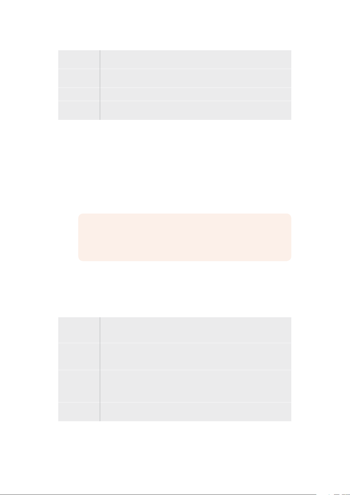
Reverse Reverse changes the progression of closed patterns such as circles, diamonds and
boxes so that the pattern closes in from the edges of the screen toward the center.
FlipFlop When FlipFlop mode is toggled on, the transition changes between normal to reverse
every time the transition is executed.
Border Width of the border.
Soft The edges of the wipe pattern can be adjusted between sharp and fuzzy by adjusting
the softness parameter.
DVE Transitions
Your ATEM switcher includes a powerful digital video effects processor for DVE transitions.
A DVE transition displaces the image in various ways to transition from one picture to another.
For example, a DVE transition can be used to squeeze the current picture off screen revealing
a new video under it.
To perform a DVE transition on the ATEM 1 M/E Advanced Panel:
1 On the preview bus, select the video source that you want on the program output.
2 Press the DVE transition type button to select the DVE transition. The DVE settings will
appear on the LCD menu.
NOTE If the DVE is already being used in an upstream key, the DVE transition
type will not be available for selection until the key is taken off air and off next
transition. Refer to ‘sharing DVE resources’ later in this section for
moreinformation.
3 In the DVE LCD menu, use the soft control knobs and buttons to configure the DVE
parameters. For example, select the DVE pattern and movement direction, and adjust
the DVE transition rate.
4 Perform the transition as an auto or manual transition using the auto button or fader bar.
DVE transition parameters
DVE Rate The duration of the DVE transition in seconds and frames. Rotate the DVE rate knob to
adjust the DVE transition rate. The new rate is immediately displayed in the transition
rate window in the transition control block.
Symmetry Symmetry can be used to control the aspect ratio of the pattern.
For example, adjusting the symmetry will allow you to change a circle into an ellipse.
On the broadcast panel symmetry can be adjusted using the z axis of the joystick.
Position If the wipe pattern has positioning then the joystick on the broadcast panel or the x
position: and y position: boxes in the transition palette of the software control panel can
be used to move the center of the pattern. Moving the joystick dynamically updates the
x and y position display in the soft ware control panel.
Normal The normal direction for closed patterns such as circles, diamonds and boxes is to grow
from the center of the screen and progress outward.
77Using External ATEM Hardware Panels
Page 78
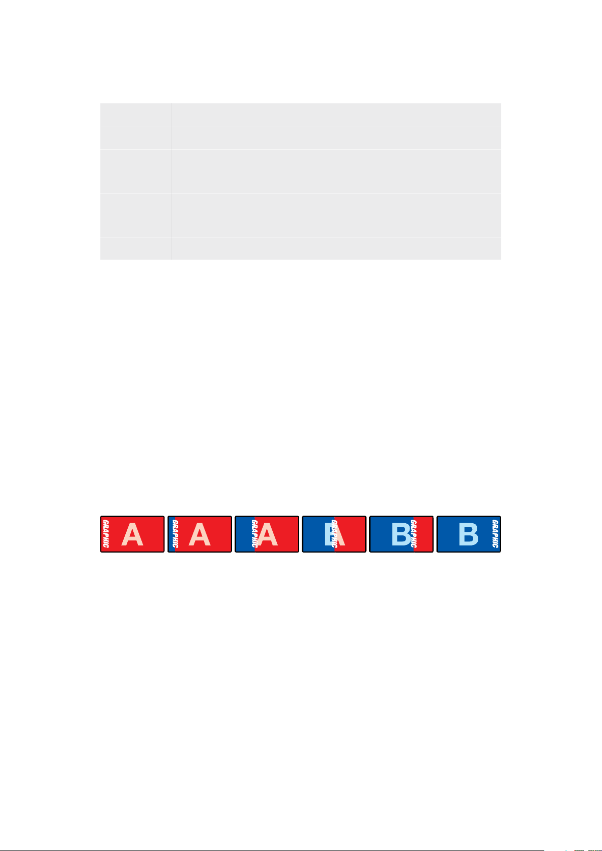
DVE key parameters
Enable key Enables/disables the DVE key. The DVE key is enabled when the button is illuminated.
PreMult Select the DVE key as a pre-multiplied key.
Clip The clip level adjusts the threshold at which the key cuts its hole. Decreasing the clip
level reveals more of the background. If the background video is completely black then
the clip value is too low.
Gain The gain adjustment electronically modifies the angle between on and off thereby
softening the edges of the key. Adjust the gain value until the edge softness is
desirable but the background video luminance (brightness) is not affected.
Inverse When the key is not pre-multiplied, inver ts the key signal.
Sharing DVE Resources
ATEM features a DVE channel which can be used to perform DVE transitions or used in an
upstream keyer. When you select a DVE transition, if the DVE is used elsewhere in the system,
the DVE transition type will not be available and a DVE unavailable message will be displayed.
In order to use the DVE transition you must free the DVE from where it is currently used. Verify
that the upstream keys currently on program or preview are not DVE keys and do not have
flying key enabled. To free DVE from the upstream keyer, change the key type to anything
other than DVE or disable flying key. The DVE will be released and therefore available for use
as a DVE transition.
The logo wipe transition is a popular transition that uses the DVE and moves a graphic across
the screen over a background transition. For example, the logo wipe moves a graphic over
ahorizontal wipe, essentially replacing the wipe border. A logo mix spins the graphic across the
screen over a mix transition. Logo transitions are perfect for wiping the station logo or spinning
a football across the screen revealing a new background. Logo transitions use a special
keyerbuilt into the transition block, leaving all of the upstream and downstream keyers
available for compositing the output.
The following section explains how to build and perform logo transitions.
The above image sequence provides an example of the program output for a graphic wipe transition.
Performing a Graphic Transition
To perform a graphic transition on the ATEM 1 M/E Advanced Panel:
1 Press the DVE transition type button in the transition control block. The DVE settings
menu will appear on the LCD.
If the DVE is already being used in an upstream key, the DVE transition type will not be
available for selection until the key is taken off air and off next transition.
Refer to ‘sharing DVE resources’ later in this section for more information.
2 Press the ‘effect’ soft button in the LCD menu to open the effect settings, and set
the effect to a graphic wipe by selecting the graphic wipe icon using the ‘effect’ soft
control knob.
78Using External ATEM Hardware Panels
Page 79

The default direction is left to right, but you can change the direction by selecting
‘reverse direction’. You can also enable ‘flip flop’ which will let the effect move forwards
and backwards with each performance of the transition, rather than repeating the same
movement direction.
3 Press the right arrow in the system control buttons to adjust the key settings. Enable
the key, and select the fill and key source. If you need to make adjustments to the key,
for example adjusting clip and gain settings, press the right arrow in the system control
buttons to access the key parameters.
TIP Typically, for a graphic transition, the source would normally be a graphic
loaded in a media player. By default, when you select a media player for the fill
source, the key source will automatically select the media player key channel
and set pre multiplied key to ‘on’. This means a graphic with a key matte
embedded in the alpha channel will automatically be selected by the switcher.
You can disable pre multiplied key and change the key source if you want to
use a separate media file on a different media player, or a different
input source.
4 Press the auto button to perform the transition as an auto transition, or use the fader
bar for a manual transition.
Graphic wipe parameters
Rate Rate specifies the length of the transition in seconds and frames.
The rate can be adjusted using the rate knob or by entering a number on the number
pad and pressing the set rate button.
Normal The normal direction moves the graphic from left to right.
Reverse Reverse changes the direction so that it moves the graphic from right to left.
FlipFlop When FlipFlop mode is toggled on, the transition changes between normal and reverse
every time the transition is executed. The ‘Normal’ or ‘Reverse’ light indicates the
direction of the next transition.
Fill Source The fill signal is the graphic used to move across the top of the transition.
Key Source The key signal is a grayscale image that defines the region in the graphic that will be
removed so that the f ill signal can be correctly stacked on top of the wipe.
Graphic wipe images
The graphic wipe feature requires a static graphic that is used as a moving border for a
horizontal wipe. This graphic should be a vertical ‘banner’ type graphic that is no more than
25% of the total screen width.
79Using External ATEM Hardware Panels
Page 80

Graphic wipe screen width requirements
1080p
1080i
720p
If the switcher is operating at 1080p then the graphic should be no wider than
1,920 pixels.
If the switcher is operating at 1080i then the graphic should be no wider than
480 pixels.
If the switcher is operating at 720p than the graphic should be no wider than
320 pixels.
Manual Transitions
Manual transitions let you manually transition between program and preview sources using the
fader bar in the transition control block. Mix, dip, wipe and DVE transitions can all be performed
as a manual transition.
To perform a manual transition
1 On the preview bus, select the video source that you want on the program output.
2 Select the transition type using the transition type buttons in the transition
control block.
3 Manually move the fader bar or transition slider from one end to the other to execute
the transition. The next move on the fader bar or transition slider will begin a
new transition.
4 During the transition the red and green buttons on the program and preview buses
both turn red to indicate that you are in the middle of a transition. The LED indicator
on the fader bar or transition slider also displays the position and progress of
thetransition.
TIP You will also see ATEM Software Control mirror the move on the
softwarepanel.
5 At the end of the transition, sources selected on the program and preview buses are
exchanged to indicate that the video source that was on preview is now on program
and vice versa.
HyperDeck Control
Introducing HyperDeck Control
When ATEM Mini is connected to a network via Ethernet, you can also connect up to
4 Blackmagic HyperDeck Studio Mini disk recorders and control them using the HyperDecks
palette in ATEM Software Control. They can also be controlled from the system control buttons
on an external ATEM hardware panel. This is a very powerful feature! With four HyperDecks
connected to your switcher, it’s like having a portable videotape department able to
record outputs from your switcher, play back graphics, or you can even set your switcher to roll
prerecorded segments at the press of a button!
Transport controls are located in the HyperDecks palette in ATEM Software Control, or in the
system control menu on an ATEM broadcast panel, which let you play back video, jog and
shuttle, skip clips, pause and more. You can also record video.
80HyperDeck Control
Page 81

When you combine this feature with ATEM’s powerful macros feature, it opens up a world of
creative possibilities that can really enhance your live production!
Connecting HyperDecks
Connecting Blackmagic HyperDecks to your ATEM Mini is very similar to connecting cameras
and other video sources via your switcher’s HDMI inputs. The only additional connection is
Ethernet which lets your ATEM Mini communicate with the HyperDeck disk recorder.
1 Make sure your external ATEM hardware panel’s internal software is updated to
version 6.8 or newer, and your HyperDeck disk recorder is running HyperDeck
software 4.3 or newer.
2 Using the Ethernet connector, connect your HyperDeck disk recorder to the same
network your ATEM Mini is connected to.
3 Enable remote control on HyperDeck Studio Mini by setting the ‘remote’ setting to ‘on’
using the LCD menu.
Plug the HDMI output of a HyperDeck Studio Mini into one of your ATEM Mini’s HDMI input s
4 Plug the HDMI output of your HyperDeck into one of the HDMI inputs of your
ATEM Mini.
5 Repeat the process for each HyperDeck you want to connect.
Now all you have to do is tell ATEM Software Control or ATEM hardware panel which input and
IPaddress each HyperDeck is using. You can do this easily in the HyperDeck tab in
ATEMSoftware Control switcher settings, or using the system control soft buttons or LCD menu
on an ATEMhardware panel.
TIP If you want to record the output from your ATEM Mini to a HyperDeck, plug your
switcher’s HDMI output into the HDMI input of the HyperDeck. Don’t forget to route the
program output to the HDMI output.
If your HyperDeck only has an SDI input, for example HyperDeck Studio Mini, you can
convert ATEM Mini’s HDMI output to SDI using a Blackmagic HDMI to SDI converter,
such as a Mini Converter HDMI to SDI, or Teranex Mini HDMI to SDI.
81HyperDeck Control
Page 82

HyperDeck Settings
HyperDeck connection settings are located in the ‘HyperDeck’ tab of the ATEM Software
Control switcher settings. Here you’ll see setup options for up to four HyperDecks.
Type in your HyperDeck’s IP address in the ‘IPAddress’ box and choosing the source it’s
plugged into from the ‘input’ dropdown menu. Click ‘connect’ and your HyperDeck is ready
to be controlled.
Status indicators appear above and below each HyperDeck icon to let you know the
connection status. A green tick means your HyperDeck is connected, in remote and
ready to go.
If your HyperDeck is connected and recognized, but does not have its remote button enabled,
you will see an indicator letting you know remote is not active.
If your HyperDeck is not recognized, you will see a ‘failed to connect’ indicator. If you see this
indicator, check the HyperDeck’s Ethernet port is connected to your network and the
IPaddress is entered correctly.
Auto Roll
You can set a HyperDeck disk recorder to automatically roll video when it is switched to the
program output. For example, you can cue a HyperDeck to the point you want your source to
begin, then roll the source by pressing its input button on the mix effects program row.
As HyperDecks must buffer a couple of frames before commencing playback, the actual cut will
be delayed a preset number of frames to ensure a clean transition. This is just like setting a
preroll on a videotape machine. You can adjust the length of this delay by changing the number
in the ‘offset’ box. We’ve found that five frames usually ensures a clean cut.
If you want to cue to a still frame of video or manually trigger video playback on your
HyperDeck, you can also deselect the ‘auto roll’ feature.
82HyperDeck Control
Page 83

Controlling HyperDecks with ATEM Software Control
To control the HyperDecks connected to your switcher, click the ‘media player’ tab in the
software control panel, and choose the ‘HyperDecks’ palette.
Here you can choose between each of the HyperDecks connected to your system by clicking
one of the four buttons along the top of the panel. These are named according to the labels
entered in ATEM settings. Available HyperDecks are shown with white text, while the
HyperDeck you are currently controlling is shown in orange.
Choose from up to four HyperDecks by clicking
their selection buttons in the HyperDecks palette
In addition to the text color, each HyperDeck’s selection button also has a tally indicator.
Green Outline
Red Outline Indicates a HyperDeck that is currently switched to the program output,
Ready HyperDeck is set to remote and a disk is inserted. It is ready for playback
Record
No Disk
Local HyperDeck is not set to ‘remote’ and cannot currently be controlled by
Indicates a HyperDeck that is currently switched to the preview output.
meaning it is currently live to air.
You may also see one of the following status indicators above the
selection buttons for your HyperDecks.
and recording if space is available.
HyperDeck is currently recording.
HyperDeck has no disk inserted.
your ATEM switcher.
When you select a HyperDeck, you’ll see information about the currently selected clip such as
the name and length, as well as time elapsed and time remaining. Below this you’ll see the
control buttons.
83HyperDeck Control
Page 84

Record
Click on this button to start recording on your HyperDeck.
Click again to stop recording.
Previous Clip
Play
Next Clip
Loop
Moves to the previous clip in your HyperDeck’s media list.
Clicking ‘play’ once initiates playback, clicking it again stops
playback. If you have ‘auto roll’ enabled in your HyperDeck settings,
playback will commence automatically when your HyperDeck is
switched to the program output.
Moves to the next clip in your HyperDeck’s media list.
Click ‘loop’ once to loop the currently selected clip, and again to
loop all of the clips in your HyperDeck’s media list.
To move through a clip use the shuttle/jog slider underneath your HyperDeck’s control buttons.
This lets you move quickly, or shuttle through a selected clip, or jog frame by frame. You can
switch between these modes with the buttons next to the shuttle/jog slider.
Choose between shuttle and jog transport controls with the
buttons to the left of the transport slider. Adjust the slider left
and right to move forward or backwards through your clip.
The clip list below the transport control shows all of the clips currently available on the selected
HyperDeck. You can expand or collapse the list by pressing the arrow to the right of the clip list.
Playback
To play media on your HyperDeck, simply switch the HyperDeck source to the preview output
and select the clip you want to show. Use the transport controls to cue to the preferred point in
your clip. When you switch your HyperDeck to program output, the ‘auto roll’ feature will
automatically start playback from this point.
If you want to manually trigger the playback, for example holding on a still frame then rolling,
simply disable the respective HyperDeck’s auto roll checkbox in the ’HyperDeck’ tab in
ATEMsoftware’s ‘settings’ menu.
Recording
To record to a HyperDeck with a formatted disk inserted, simply press the ‘record’ button in the
HyperDeck palette transport controls. The ‘time remaining’ indicator in the HyperDeck palette
will let you know the approximate recording time remaining in the SSD.
Controlling HyperDecks with External Hardware Panels
If you are using an external ATEM hardware panel, you can control any connected HyperDecks
using the hardware panel. Once you have connected your HyperDecks to your ATEM Mini as
described in the ‘connecting HyperDecks’ section, you can use the system control buttons and
LED menu on your panel to set up and control each HyperDeck.
84HyperDeck Control
Page 85

HyperDeck Setup with ATEM 1 M/E Advanced Panel
Once you have connected your HyperDeck to your switcher, as detailed in the ‘connecting
HyperDecks’ section, use ATEM 1 M/E Advanced Panel’s system control and LCD soft buttons
to setup and control your HyperDecks.
To begin, press the system control ‘settings’ button.
You’ll notice that ATEM 1 M/E Advanced Panel displays four setup options along to top of the
LCD screen. These include ‘switcher,’ ‘panel,’ ‘HyperDecks,’ and ‘button mapping.’
Each corresponds to a setup menu. Simply press the LCD soft button above ‘HyperDecks’ to
enter the ‘HyperDeck settings’ menu.
The HyperDeck settings menu has three pages, which you can select using the ‘left’ and
‘right’ arrow buttons in the system control panel, or by pressing the ‘1,’ ‘2,’ and ‘3’ buttons on
your ATEM 1 M/E Advanced Panel’s numerical keypad.
Assigning an input to a HyperDeck
In the first menu page, you’ll see the ‘HyperDeck’ indicator in the bottom left corner, and an
‘input’ indicator.
Use the control knob under the ‘HyperDeck’ indicator to cycle through the available
HyperDecks.
Once you have selected a HyperDeck, simply rotate the knob under the ‘input’ indicator to
select which input that HyperDeck is connected to on your switcher. For example,
if HyperDeck 1 is connected to SDI In 4 on your switcher, rotate the knob under the ‘input’
indicator to select ‘camera 4.’ Press the ‘input’ knob to confirm your selection.
Repeat this process for any
additional HyperDecks you
have connected to your
switcher by assigning inputs
to HyperDeck slots 1, 2, 3
and 4, if required.
Assigning an IP Address
Once you’ve assigned an input to a HyperDeck, you’ll need to enter its IP address.
This allows ATEM 1 M/E Advanced Panel to control the HyperDeck via Ethernet.
85HyperDeck Control
Page 86

To enter a HyperDeck’s IP address, navigate to the third HyperDeck settings page with the
‘left’ or ‘right’ arrow buttons, or pressing ‘3’ on the numeric keypad while in the HyperDeck
settings menu.
In this page, you’ll see an IP address for the currently selected HyperDeck. Each IP address
number corresponds to a rotary knob below it. To change these numbers, you can rotate the
corresponding knob, or press the knob once and enter a number using the numeric keypad.
Do this for each number in the IP address.
Once you’ve entered the IP address for your HyperDeck, press the soft button corresponding
to the ‘save changes’ indicator to confirm the address. To cancel, press ‘undo’.
To enter the IP address
for subsequent
HyperDecks, you’ll need
to select the HyperDeck
using the first page of the
HyperDeck settings menu.
Auto Roll
You can toggle your HyperDeck’s auto roll function from the second screen of the HyperDeck
settings menu. While in the HyperDeck settings menu, use the ‘left’ or ‘right’ arrow buttons in
the system control panel to navigate to this screen.
While in this menu, press the LCD soft button above the ‘auto roll’ indicator to turn the auto roll
feature on. The indicator text will illuminate blue when auto roll is on.
The auto roll feature lets you set a HyperDeck disk recorder to automatically roll video when it
is switched to the program output. For example, you can cue a HyperDeck to the point you
want your source to begin, then roll the clip by pressing the HyperDeck’s input button on the
program row.
As HyperDecks must buffer a couple of frames before commencing playback, the actual cut will
be delayed a preset number of frames to ensure a clean transition. This is just like setting a
preroll on a videotape machine. You can adjust the length of this delay by changing the ‘offset’
frames number using the control knob under this indicator. Press the soft button above the
‘save changes’ indicator to confirm your change.
86HyperDeck Control
Page 87

Controlling HyperDecks with ATEM 1 M/E Advanced Panel
HyperDeck controls are available in the ‘media players’ menu in your ATEM 1 M/E Advanced
Panel. To access this menu, simply press the ‘media players’ control panel button and press the
soft button above the ‘HyperDecks’ indicator to access HyperDeck control. If your switcher has
more than two media players, you may need to navigate to the next menu page to access
HyperDeck controls.
You can now use the rotating
knobs below the ‘hyperdeck,’
‘clip,’ ‘jog’ and ‘shuttle’ indicators
to select HyperDecks, select clips,
and jog and shuttle these clips.
The text in the center of
the HyperDeck control menu will
change to reflect the HyperDeck
and clip that you have selected.
Use the third and fourth pages
of the ‘media players’ LCD menu
for more HyperDeck controls,
including play, stop, loop playback,
and forward and reverse skip for
moving between clips.
In the fourth menu page, press
the ‘record’ button to record the
program output of your switcher
to your HyperDeck. Use the ‘jog’
and ‘shuttle’ commands to scrub
through recorded footage.
87HyperDeck Control
Page 88

TIP To play all clips, hold down the shift button and press the ‘play’ soft button.
Keying using ATEM Mini
Keyers are a powerful production tool that allow the arrangement of visual elements from
different sources on the same video image.
To do this, multiple layers of video or graphics are stacked on top of the background video.
Altering the transparency of various parts of these layers allows the background layer to be
visible. This process is called keying. Various techniques are used to create this selective
transparency and these correspond to the different types of keyers available on your switcher.
The following section explains luma and linear keyers, which are available either upstream or
downstream, and chroma, pattern and DVE keys, which are upstream keyers.
Understanding Keying
A key requires two video sources; the fill signal and the key or cut signal. The fill signal contains
a video image which is to be stacked on top of the background, while the cut signal is used to
select regions of the fill signal to be made transparent. The fill and cut signals can be selected
from any of the switcher’s external inputs or internal sources, allowing both still and moving
images to be used as fill or cut sources.
Fill and cut signals are selected on the software control panel from drop down lists in the
upstream and downstream key palettes. In your switcher’s LCD menu, you can select fill and cut
signals in the upstream or downstream key menus.
There are two types of keyers used in your switcher; upstream keyers and downstream keyers.
One upstream keyer, also known as an effects keyer, plus two downstream keyers are available
via the switcher’s control panel and LCD menu, or via ATEM Software Control. The upstream
keyer can be set up as a luma, linear, pre-multiplied, chroma, pattern or DVE key. Two
downstream keyers are available in the dedicated DSK block. Each downstream keyer can be
set up as a luma or linear key.
Luma Key
A luma key or self key consists of one video source containing the video image that will be
stacked on top of the background. All of the black areas defined by the luminance in the video
signal will be made transparent so that the background can be revealed underneath. Since only
one image is used to define the areas to be cut out, a luma key uses the same signal for the fill
and key. The following images are an example of what background, luma key signals and the
resulting combined image might look like.
Combining a background and fill/key in a luma key
Background
A full screen image, often a camera source.
88Keying using ATEM Mini
Page 89

Fill
The graphic you plan to display on top of your background video. Notice that the final
composition does not retain any black from the graphic because all of the black parts have
been cut out of the image.
Linear Key
A linear key consists of two video sources, which are the fill signal and the key or cut signal.
The fill signal contains a video image which is to be stacked on top of the background, while
the key signal contains a grayscale mask that is used to define regions of the fill signal to be
made transparent. Since both the fill and key signals are video inputs, both signals can be in
motion while on screen. The following images are examples of what background, fill and key
signals, and the resulting combined image might look like.
Combining a background, fill and key in a linear key
Background
A full screen image, often a camera source.
Fill
The graphic you plan to display on top of your background video. Notice that the black parts of
the graphic remain intact because the key signal is used to determine the transparency of the
fill signal. The fill signal is often provided by a graphics system.
Key
A grayscale image that defines the region in the image that will be removed so that the fill
signal can be correctly stacked on top of the background. The key signal is often provided by a
graphics system.
Pre multiplied Key
A modern graphics system or character generator that offers fill and key outputs will most likely
provide what is known as a pre multiplied or shaped key. A pre multiplied key is a special
combination of the fill and key signal where the fill signal has been pre multiplied with the key
signal over a black background. Photoshop generated images that contain an alpha channel are
pre multiplied.
ATEM switchers have an auto key adjustment for pre multiplied keys so that when the pre
multiplied key setting is enabled, the clip and gain parameters are automatically set by
the system.
When using a Photoshop generated image, generate graphics over a black background layer
and place all content on the upper layers. Add an alpha channel in your Photoshop document
that the ATEM can use for blending the graphic over the live video. Then, when saved as a
Targa image file, or downloaded direct to the media pool, you can select pre multiplied in the
keyer and you should have a great key!
Photoshop documents are pre multiplied by nature, so you should always use the pre multiplied
settings on the ATEM switcher when keying them.
89Keying using ATEM Mini
Page 90

Performing an Upstream Luma/Linear Key
Since luma and linear keys use the same parameters, they are set up on the software control
panel and broadcast panel using a common menu, called the luma key menu. What def ines the
key as being either luma or linear is in the selection of fill and key sources. In a luma key, fill and
key sources are the same. For a linear key, fill and key sources are different.
To set up a luma/linear key on the upstream keyer in ATEM Software Control:
1 Expand the upstream key 1 M/E 1 palette and select luma tab.
2 Select the fill source and key source.
If performing a luma key, select the same source for both fill and key.
Adjust the key parameters to refine the key. For a description of luma key parameters, refer to
the table below.
Select sections of the Palette you wish
to reset from the reset menu
Upstream key luma/linear key parameters:
Mask Enables a rectangular mask that can then be adjusted using the top,
bottom, left and right parameters.
Pre-Mult Identifies the key signal as a pre-multiplied key.
Clip The clip level adjusts the threshold at which the key cuts its hole.
Decreasing the clip level reveals more of the background. If the
background video is completely black then the clip value is too low.
Gain The gain adjustment elec tronically modifies the angle between on and off
thereby softening the edges of the key. Adjust the gain value until the edge
softness is desirable but the background video luminance or brightness is
not affected.
Invert Key Inverts the key signal.
Flying Key Enables/disables DVE effects.
90Keying using ATEM Mini
Page 91

Setting up a Luma/Linear Key on the Upstream Keyer using
ATEM 1 M/E Advanced Panel
1 Press the ‘key 1’ button to enable the keyer on the preview output. This
automatically selects the keyers menu on the system control LCD, but you can
also press the ‘keyers’ button to enter the menu directly.
2 Select the desired M/E keyer by pressing the corresponding soft button along the
top edge of the LCD menu.
3 Use the control knob underneath the ‘key type’ indicator to choose the ‘luma’ key.
4 Rotate the ‘fill source’ and ‘key source’ control knobs to choose a fill and key
source. You can also press the corresponding buttons on the source select bus to
select the fill and key source.
5 Once you have chosen a key type, fill and source, press the ‘right’ arrow button
to scroll through to the next menu item and use the control knobs to adjust key
parameters such as mask, gain, clip, enable or disable pre multiplied key, etc.
To set up a luma/linear key on downstream keyer in ATEM Software Control:
1 Select the downstream key 1 palette.
2 Use the drop down controls labeled fill source and key source to specify the fill and key
sources. If performing a luma key, select the same source for both fill and key.
3 Adjust the key parameters to refine the key.
Downstream Keyer Settings
91Keying using ATEM Mini
Page 92

Setting up a Luma/Linear Key on the Downstream Keyer using
ATEM 1 M/E Advanced Panel
1 Press the ‘DSK 1 tie’ button to enable the downstream keyer on the preview
output. This automatically selects the downstream key menu on the system control
LCD, but you can also press the ‘keyers’ button and press the right arrow to enter
the menu directly.
2 Press the ‘DSK 1’ or ‘DSK 2’ soft button to select which downstream keyer you wish
to use. You don’t have to select the key type as the downstream keyer is always
a luma key.
3 Use the control knobs under the LCD menu to select the fill source and key
source. You can also use the corresponding source select buttons to select the fill
and key source.
4 Once you have chosen the fill source and key source, use the ‘left’ and ‘right’
control buttons to scroll through additional menu screens containing key
parameters such as mask, gain, clip, pre multiplied key settings, and more.
Chroma Key
Chroma key is commonly used for weather broadcasts, where the meteorologist appears to be
standing in front of a large map. In the studio the presenter is actually standing in front of a blue
or green background. In a chroma key two images are combined using a special technique and
a color from one image is removed, revealing another image behind it. This technique is also
referred to as color keying, color-separation overlay, green screen, or blue screen.
A very common use for chroma keys for backgrounds is computer generated graphics.
It’ssimple to connect an external computer to your ATEM switcher using the HDMI output of the
computer or a video card such as the Blackmagic Design DeckLink or Intensity range and then
play back video clips to your ATEM switcher. If you render a green background on your
animations, you can then key this green to create fast and clean animations of any length.
Keying is easy as the green is computer generated so it’s a very flat color that’s easy to key.
Combining a background with a fill and chroma key mask
Background
A full screen image; in the case of a chroma key it is often a weather map.
Fill
The image you plan to display on top of your background video. In the case of a chroma key,
this is video of the meteorologist in front of the green screen.
Key/Cut
In the case of a chroma key the key/cut signal is generated from the fill signal.
92Keying using ATEM Mini
Page 93

Performing a Chroma Key
ATEM Mini features an advanced chroma keyer with detailed chroma sampling and adjustment
options. These controls help you achieve the best key, improving the blend of foreground and
background so you can create a more convincing visual effect.
To set up a convincing chroma key using the advanced keyer:
1 In ATEM Software Control, expand the upstream key palette and select ‘chroma’ from
the key types bar.
2 Select the fill source. Typically, this source would be from a camera facing a presenter
in front of a green screen, or a graphic loaded in a media player.
3 Click the ‘chroma sample’ button. With the chroma sample selected, you’ll see a new
panel appear with a box cursor. This cursor is also visible on the preview output.
4 Click and drag on the box cursor to move it to the position you want to sample.
The chroma sample setting lets you position a cursor over the screen area you want to sample
Choose a representative area of your green screen that covers as much of the luminance range
of the screen as possible. The default size of the box cursor is well suited to most green
screens that are relatively evenly lit, however if there is a lot of variance in your green screen,
you can adjust the size of the box by clicking on the slider to the right of the sample window
and dragging it up or down.
TIP When sampling uneven green screens, we recommend sampling the darkest
area first before increasing the size of the sample box. This can give you a more
accurate key.
NOTE You can preview your key on the preview output via HDMI at any time by
clicking the ‘preview’ button above the chroma sample panel. This shows you the final
composited version of your chroma key effect on the preview.
93Keying using ATEM Mini
Page 94

Click the preview button to check the final composite on the preview output
Fine Tuning your Key using Key Adjustments
Once you have achieved a good chroma sample that removes most of your green screen
whilegenerally retaining foreground elements, its time fine tune your key with the
‘key adjustments’ controls.
Foreground
Use the ‘foreground’ slider to adjust how opaque the foreground mask is. This determines the
strength of the foreground against the background. By increasing the slider, you can fill in any
small areas of transparency inside your foreground image. We recommend moving this slider
and stopping as soon as the foreground becomes solid.
Background
The ‘background’ slider adjusts the opacity of the keyed area. Use this slider to fill in any small
foreground artifacts left over in the area of the image you want to remove. We recommend
moving the slider until your keyed area is consistently opaque.
Key Edge
The “key edge” slider moves the edge of your keyed area in or out, helping to remove
background elements from the very edge of your foreground or extending the foreground out
a little if your key is too aggressive. This can be especially useful with fine details like hair.
We recommend moving this slider until the edge of your key is generally clean, without any
background artifacts visible.
Using the key adjustment controls, your foreground elements should be cleanly separated from
the background.
Chroma Correction using Color Spill and Flare Suppression
Light bouncing off a green screen can create a green edge to foreground elements as well as
ageneral tint to the foreground, or fill image. This is called color spill and flare. The ‘chroma
correction’ settings let you improve the areas of the foreground that are affected by color spill
and flare.
Spill
Adjust the spill slider to remove colored tint from the edges of foreground elements.
For example, green reflections bouncing off a green screen.
Flare Suppression
Flare suppression removes overall green tint evenly across all foreground elements.
94Keying using ATEM Mini
Page 95

Matching your foreground and background
Once your foreground is properly separated from your green screen, and you have adjusted
spill and flare suppression, use the ‘color adjustments’ controls to match your foreground with
the background. Adjusting the brightness, contrast, saturation, and color balance of your
foreground image will help blend it with the background so the effect is more convincing.
Use the color adjustments controls to match your foreground with the background
TIP When your key is on air, chroma sampling and preview are locked. While most
controls are adjustable while on air, we recommend avoiding changes unless
absolutely required. For example making def ined color adjustments ifconditions
change unexpectedly.
Pattern Key
A pattern key is used to display a geometric cut out of one image on top of another image.
In a pattern key the key or cut signal is generated using the switcher’s internal pattern
generator. The internal pattern generator can create 18 shapes that can be sized and positioned
to produce the desired key signal.
Combining a background with a fill and pattern key
95Keying using ATEM Mini
Page 96

Background
A full screen image.
Fill
Another full screen image you wish to overlay on top of the background.
Key/Cut
In the case of a pattern key the key/cut signal is generated by the switcher’s internal
pattern generator.
Pattern Key Settings
To set up a pattern key on the upstream keyer in ATEM Software Control:
1 Expand the upstream key palette and select pattern from the key types bar.
2 Select the fill source.
3 Select the key pattern.
4 Adjust the key parameters to refine the key. For a description of pattern key
parameters, refer to the table below.
96Keying using ATEM Mini
Page 97

Pattern key parameters:
Invert Pattern This but ton inverts which the region is f illed with the fill source.
For example, fill a region outside of a circle by positioning the circle wipe as
desired and then setting invert pattern to ‘on’.
Size Increases and decreases the size of the selec ted pat tern.
Symmetry Some patterns may have their symmetr y or aspect ratio adjusted.
Circle patterns may be adjusted to become horizontal or vertical ellipses.
Softness Changes the softness of the edge of the key signal.
Position X and Y These settings let you change the position of the pattern on the screen.
Mask Allows you to mask out sections of the key. For example, if the green screen
does not f ill the edges of the screen, you can use the mask setting to select
only the area of the screen you want to use.
To return the mask to its default symetrical settings, select ‘reset mask’ and
press the set button.
Setting up a Pattern Key on the Upstream Keyer using
ATEM 1 M/E Advanced Panel
1 Press the KEY 1 next transition button to enable the key on the preview output.
Thisautomatically selects the keyers menu on the system control LCD. Pressing
the KEY 1 next transition button ties the key to the next transition so it will transition
to air when the next transition is performed.
2 In the keyers LCD menu, select the ‘pattern’ key type using the corresponding
‘keytype’ control knob.
3 Select the fill source using the corresponding soft control knob or by pressing
asource button on the source select bus.
4 Turn the corresponding soft control knobs to choose the ‘pattern’ you want for
thepattern key and set the ‘size’ of the pattern.
5 Press the system control left and right arrow buttons to navigate through the
pattern key parameters, and adjust settings using the control knobs. Watch the
preview output as you refine the key.
TIP Some patterns can have their center point repositioned. Use the joystick to move
the position of the pattern. If you need to reset the position, navigate to the ‘pattern
type’ setting, change it to another pattern, and then return to your chosen pattern to
rest the position to its default.
97Keying using ATEM Mini
Page 98

DVE Key
DVEs, or digital video effects, are used to create picture-in-picture boxes with borders.
Mostmodels have 1 channel of 2D DVE that allows scaling, rotation, 3D borders and offers a
drop shadow.
Combining a background, DVE f ill and DVE key/cut
Background
A full screen image.
Fill
Another full screen that has been scaled, rotated or has added borders and will be overlaid on
top of the background.
Key/Cut
In the case of a DVE key, the key/cut signal is generated by the switcher’s internal
DVEprocessor.
To set up a DVE key on the upstream keyer in ATEM Software Control:
1 Expand the upstream key palette and select the DVE tab.
2 Select the fill source.
3 Adjust the key parameters to refine the key. For a description of DVE key parameters,
refer to the information below.
Adjusting the x/y position of the DVE
You can independently adjust the x and y positions of the DVE using the position X and Y
settings, or you can tie X and Y parameters together so adjusting one will automatically adjust
the other. To achieve this, simply enable the ‘tie X and Y’ setting.
This also applies to the size parameters.
DVE parameters
Size X Adjusts the horizontal size of the DVE.
Size Y Adjusts the vertical size of the DVE.
Reset DVE Resets the DVE to screen. Useful if you lose track of the DVE during adjustment.
98Keying using ATEM Mini
Page 99

Adding DVE Borders
DVE border parameters
The upstream key LCD menu is used to adjust the border parameters for the DVE and picture
in picture.
Border Enables or disables the border.
Color This item appears greyed out because it is not a setting, but rather
an indicator to show you the selected border color. You can use this
indicator to quickly verify the color of the DVE border.
Hue Changes the border color. The hue value is a location on the color wheel.
Saturation Changes the intensity of the border color.
Luminance Change the brightness of the border color.
Style Sets the bevel style for the DVE border.
Outer Width Adjusts the outside width of the border.
Inner Width Adjusts the inside width of the border.
Outer Soften Outside softness adjusts the outside edge of the border, the edge that
touches the background video.
Inner Soften Adjusts inside sof tness. This softness parameter adjusts the inside edge of
the border, the edge that touches the video.
Border/Shadow
Opacity
Bevel Position Adjusts the position of the 3D bevel on the border.
Bevel Soften Bevel sof tness adjusts the overall sof tness of the 3D border. A high value
Opacity adjusts the transparency of the border and shadow, use this setting
to create interesting colored glass borders.
for this parameter will result in a rounded or beveled border.
DVE shadow light source parameters
Enable Shadow Enables or disables the drop shadow.
Angle Adjusts the direction of the light source on the DVE or picture in picture.
Both the border and drop shadow, if available, are affec ted by changes to
this setting.
Altitude Adjusts the distance of the light source from the DVE or picture in picture.
Both the border and drop shadow, if available, are affec ted by changes to
this setting.
99Keying using ATEM Mini
Page 100

Setting up a DVE Key on the Upstream Keyer using
ATEM 1 M/E Advanced Panel
1 Press the KEY 1 next transition button to enable the keyer on the preview output.
2 In the keyers LCD menu, select the DVE key type using the corresponding soft
control knob.
3 Select the fill source using the corresponding control knob or via the a source
button on the source select bus.
4 Press the system control left and right arrow buttons to navigate through the
DVE parameters, and use the soft control knobs to adjust settings, such as
rotation, position, size, mask settings, light source, border, and key frames
for movement.
Key Masking
Both upstream and downstream keyers have an adjustable rectangular mask that can be used
to crop out harsh edges and other artifacts in the video signal. The mask consists of left, right,
top and bottom crop controls. Masking can also be used as a creative tool to build rectangular
cut outs on screen.
The mask can be adjusted using the mask settings in the switcher’s LCD menu, or via the
upstream and downstream keyer palettes in ATEM Software Control.
Flying Key
Luma, chroma and pattern upstream key types include a flying key setting. If a DVE channel is
available the flying key setting allows DVE effects to be applied to the key.
Performing Upstream Keyer Transitions
Performing an upstream keyer transition in ATEM Software Control:
The upstream keyer is taken on and off the program output using the ‘next transition’ control
buttons in ATEM Software Control.
Key 1
Take the upstream keyer on or off the program output by clicking the ‘on air’ button.
You will notice this is also reflected by the ‘key’ button on ATEM Mini’s control panel.
Changing the ‘on air’ setting in the LCD menu also changes the state
of the ‘on air’ next transition button in ATEM Sof tware Control
100Keying using ATEM Mini
 Loading...