

Page 1
Installation and Operation Manual
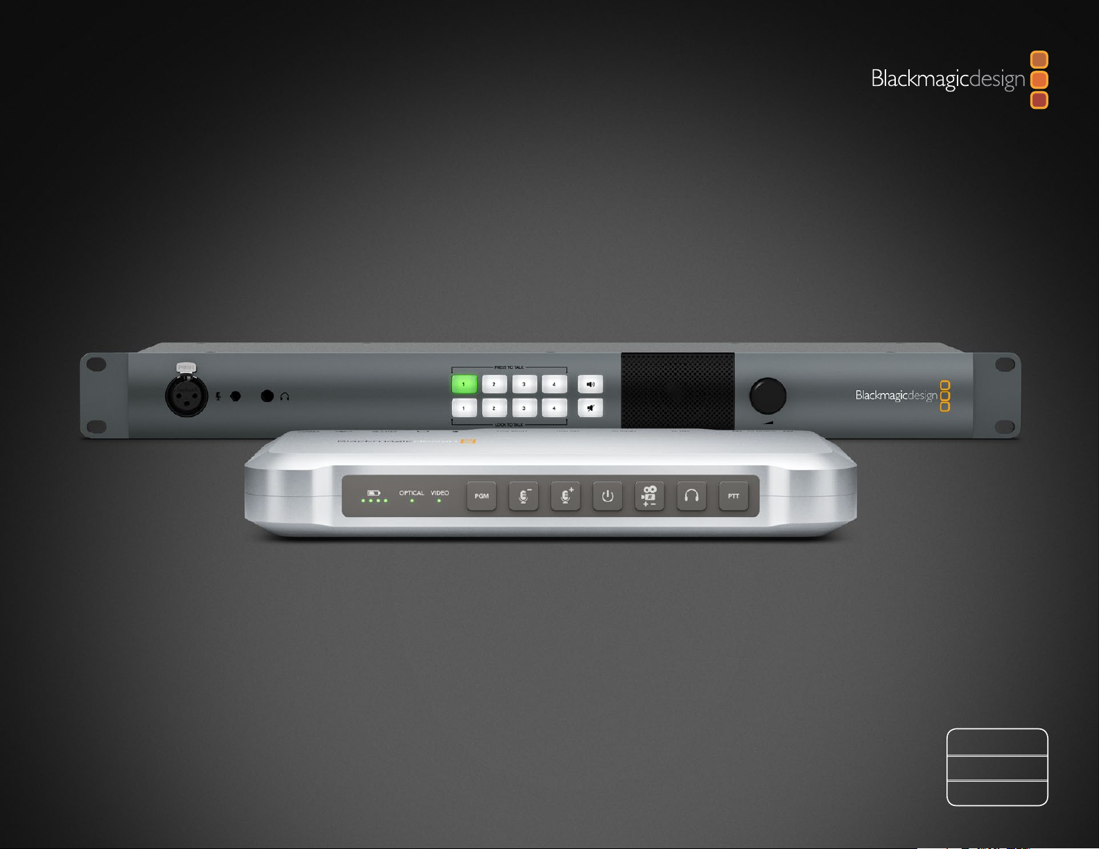
ATEM Camera Converter
ATEM Studio Converter
Mac OS X
Windows
August 2013
™
™
Page 2
Welcome
Welcome to ATEM Live Production!
Thank you for purchasing a Blackmagic Design converter for your live
production work!
ATEM Camera Converter and ATEM Studio Converter allows you to extend your
broadcast SDI and consumer HDMI cameras using low cost optical fiber! Imagine
connecting to cameras at remote locations on racing tracks, live sporting venues
or even massive golf courses! With ATEM Camera Converter you can have more
cameras closer to the action for the most amazing shots in live production! ATEM
Camera Converter not only converts your camera to optical fiber, but it also includes
talkback, external microphone input, program return feed, tally and built in battery
power source! You can place cameras in multiple locations miles away from your
switcher while keeping full broadcast HD video quality!
ATEM Studio Converter is the perfect partner for your ATEM Camera Converters for
internally distributed program output and talkback support. Multiple ATEM Studio
Converters can be looped to allow talkback support to more than 4 cameras.
Blackmagic Converter Utility is used to change settings and update the internal
software in your ATEM converter. The latest version of Converter Utility can always
be downloaded from our website at www.blackmagicdesign.com/support. We
think it should take you approximately 5 minutes to complete installation. Before
you install Converter Utility, please check our website and click the support page to
download the latest updates to this manual and Converter Utility software. Lastly,
please register your ATEM Camera Converter or ATEM Studio Converter when
downloading software updates.
We would love to keep you updated on new software updates and new features
for your ATEM converters. Perhaps you can even send us any suggestions for
improvements to the converters. We are constantly working on new features and
improvements, so we would love to hear from you!
Grant Petty
CEO Blackmagic Design
Page 3
Contents
ATEM Converters
4
10
Getting Started
Introducing ATEM Converters 4
Getting Started with ATEM Camera Converter 5
Plugging in your Power 5
Plugging in your Camera 5
Plugging in your Headset 5
Plugging in your Monitor 5
Plugging in your Audio 6
Connecting ATEM Converters via Optical Fiber Cables 6
Confirming Your Video Signal 6
Getting Started with ATEM Studio Converter 7
Plugging in Power 7
Plugging in your Headset 7
Plugging in your External Microphone 7
Outputting Camera Audio 7
Monitoring your Audio 7
Connecting to a Switcher 8
Confirming your ATEM Converter Set Up 9
Using ATEM Camera Converter
Using ATEM Camera Converter 10
Status Indicators 10
Control Panel Buttons 11
Setting the Camera Number 12
Mounting ATEM Camera Converter 12
13
14
17
18
19
20
Using ATEM Studio Converter
Using ATEM Studio Converter 13
Using Blackmagic Converter Utility
Blackmagic Converter Utility 14
Installing Blackmagic Converter Utility on Mac OS X 14
Installing Blackmagic Converter Utility on Windows 14
Updating the Converters Software 14
Setting Tally Border and Camera Number Using Blackmagic
Converter Utility 15
Connecting Up to 4 Cameras to a Switcher 16
Connecting to an ATEM Switcher
Connecting More than 4 Cameras to a Switcher 17
Help
Warnings
Warranty
Page 4
4
Getting Started
ATEM Camera Converter
ATEM Studio Converter
Getting Started
Introducing ATEM Converters
ATEM Camera and Studio Converters connect to switchers, such as ATEM production switchers, and allow
cameras to be connected over long distances using low cost, fiber optic cable.
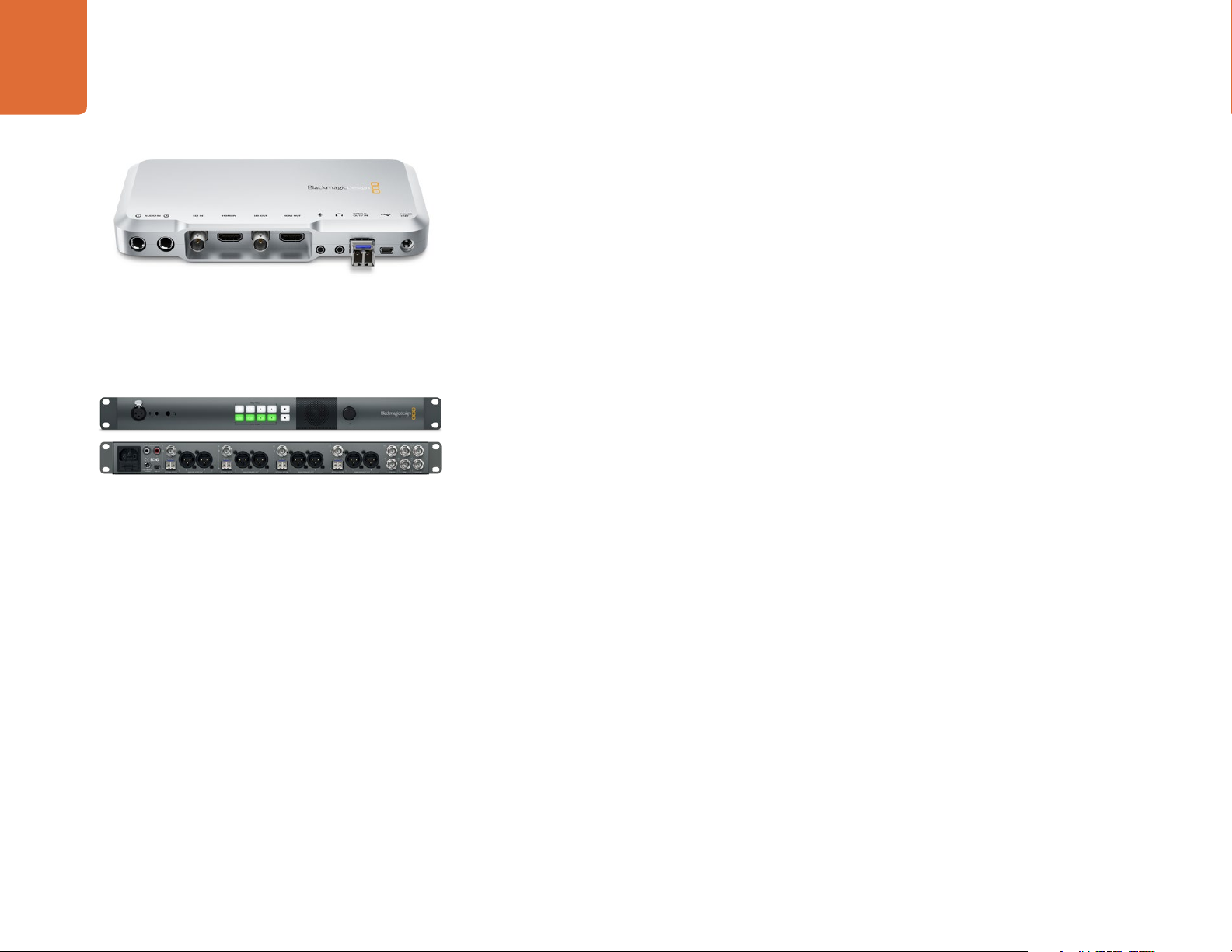
ATEM Camera Converter
ATEM Camera Converter connects to any camera with HDMI or SDI output in SD, HD and 3Gb/s HD-SDI
formats. It is used to send video, audio, tally and talkback signals via optical fiber between the camera unit
and a remote unit, for connection to a switcher. It can be battery operated or run on mains power.
When only one camera is being used, a pair of ATEM Camera Converters are required to extend the camera
over a long distance and provide talkback between the camera operator and the switcher operator.
ATEM Studio Converter
When multiple cameras are being used, ATEM Camera Converters can be partnered with an ATEM Studio
Converter. Each ATEM Studio Converter supports connections to 4 ATEM Camera Converters. If the
switcher operator needs to communicate with more than 4 cameras, additional ATEM Studio Converters
can be looped together and connected to more ATEM Camera Converters.
Single mode optical fiber cable with LC connectors are used to connect ATEM Camera Converter, ATEM
Studio Converter and other optical fiber SDI products from Blackmagic Design.
ATEM Camera and Studio Converters are connected to a switcher via SDI cables.
Page 5
5
PTTPGM
PTTPGM
PTTPGM
VIDEOOPTICAL
PTTPGM
Getting Started
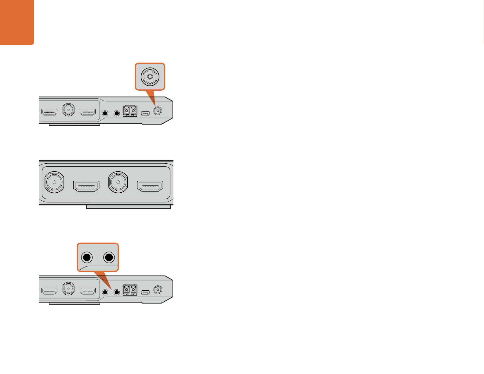
Plug in your power source and charge the internal battery via the
12V to 31V power connector.
Connect your camera via the SDI or HDMI input, and your
monitor via the SDI or HDMI output. By default, ATEM Camera
Converter uses embedded SDI or HDMI audio from your camera.
Getting Started with ATEM Camera Converter
The first thing you’ll want to do is power your ATEM Camera Converter, plug in your camera, headset and a
monitor. You can also plug in an external audio source, such as a mixing desk or microphone.
Plugging in your Power
ATEM Camera Converter features both an internal rechargeable battery which gives you mobility in the
field, and a connector for plugging in the power adaptor supplied with ATEM Camera Converter. ATEM
Camera Converter’s power connector supports an input range of 12V to 31V so you can even use an external
camera battery. The internal battery will charge when a power source is connected.
Plugging in your Camera
You can plug in your camera using ATEM Camera Converter’s SDI or HDMI connectors. SDI connections are
robust, industrial standard and reliably used with long cables up to 300 feet or 100 meters in length. If your
camera has a HDMI output, plug in via a HDMI type A connector and cable.
Make sure your camera output is set to a format supported by your live production switcher.
1080p cameras will usually need to be adjusted to output 1080i or 720p for broadcast. If you’re
connecting to an ATEM switcher, check the switcher video standard and then set the camera to the same
video standard, e.g., 1080i59.94.
Plugging in your Headset
Plug your talkback headset into ATEM Camera Converter’s standard 3.5mm stereo analog microphone
and headphone inputs. An iPhone-compatible headset can be connected using only the headphone jack.
However, if both an iPhone-compatible headset and external microphone are connected at the same time,
only the external microphone will be used.
Connect your headset to ATEM Camera Converter via standard
3.5mm TRS phone inputs.
Plugging in your Monitor
Plug your monitor into ATEM Camera Converter's SDI or HDMI output. Using a monitor lets you view the
camera output or the program output from a switcher. ATEM switchers send tally via the SDI signal. When
the camera is switched to the program output, the tally signal will activate a red border on your attached
monitor to show the camera is on air.
Page 6
6
PTTPGM
VIDEOOPTICAL
PTTPGM
VIDEOOPTICAL
PTTPGM
PTTPGM
PTT
Getting Started
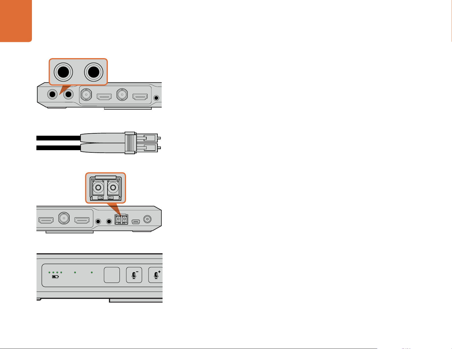
Connect external audio equipment to ATEM Camera Converter
via TRS phone connectors.
Optical fiber patch cord with two LC connectors.
Plugging in your Audio
ATEM Camera Converter supports 2 channels of camera audio, which are carried on audio channels 1 & 2
of the optical fiber SDI connection. By default, ATEM Camera Converter uses the embedded audio from
your camera's microphone. However, if you want to plug in an external audio source, connect your audio
equipment to ATEM Camera Converter’s two balanced 1/4" TRS inputs. When external audio is connected
it will be used instead of the embedded camera audio.
The 1/4" TRS connectors accept stereo analog audio at microphone level and are carried on audio channels
1 & 2 of the optical fiber SDI connection.
Connecting ATEM Converters via Optical Fiber Cables
You’ll now want to connect your ATEM Camera Converter to a second Camera Converter or an ATEM
Studio Converter via duplex single mode optical fiber cables with LC connectors. A pair of optical fiber
cables are typically known as a patch cord and have the connectors' positions swapped on one end so
optical out is connected to optical in on each unit.
Plugging in Optical Fiber LC Connectors
To plug optical fiber connectors into your ATEM Converters:
Step 1. Plug one end of the patch cord to your ATEM Camera Converter’s SFP module.
Step 2. Plug the other end of your patch cord to the SFP module on the second ATEM Camera Converter.
If you are connecting multiple cameras to an ATEM Studio Converter, choose an SFP module appropriate
for each camera. For example, when connecting camera 1, connect to ATEM Studio Converter’s camera 1
module.
ATEM Camera Converter's optical fiber SFP module.
VIDEOOPTICAL
When a valid SDI or HDMI signal is present, you’ll see ATEM
Camera Converter's Video status indicator illuminated.
PGM
When your ATEM Camera Converter is powered, a camera is plugged in, and a valid SDI or HDMI signal is
present, you’ll see the control panel Video status indicator illuminated. Additionally, if you have your monitor
connected and the PGM button set for camera video, your camera output will be displayed and you’ll know
your ATEM Camera Converter is working.
Confirming Your Video Signal
Page 7

7
4
L R
ANALOG AUDIO OUT OPTICAL OUT/IN
SDI OUT
L
OUT
R
ANALOG AUDIO OUT
IN
PGM SDI
OUT
IN
MIC
OUT
IN
H/PHONE
AES/EBU TALKBACK LOOPS
LOCK TO TALK
PRESS TO TALK
4321
L R
ANALOG AUDIO OUT OPTICAL OUT/IN
SDI OUT
L
OUT
R
ANALOG AUDIO OUTANALOG AUDIO OUT
IN
PGM SDI
OUT
IN
MIC
OUT
IN
H/PHONE
AES/EBU TALKBACK LOOPS
LOCK TO TALK
PRESS TO TALK
43
R
ANALOG AUDIO OUT OPTICAL OUT/IN
SDI OUT
L R
ANALOG AUDIO OUT OPTICAL OUT/IN
SDI OUT
L
OUT
R
ANALOG AUDIO OUT
IN
PGM SDI
OUT
IN
MIC
OUT
IN
H/PHONE
AES/EBU TALKBACK LOOPS
PUSH
LOCK TO TALK
PRESS TO TALK
4321
RL
OUT
OUT
OUT
AES/EBU TALKBACK LOOPS
LOCK TO TALK
PRESS TO TALK
4321
OPTICAL OUT/IN
SDI OUT
L R
RL
USB 2.0
+12V BACKUP
POWER
OPTICAL OUT/IN
SDI OUT
L R
ANALOG AUDIO OUT OPTICAL OUT/IN
SDI OUT
L R
ANALOG AUDIO OUT OPTICAL OUT/IN
SDI OUT
L
OUT
R
ANALOG AUDIO OUTANALOG AUDIO OUT
IN
PGM SDI
OUT
IN
MIC
OUT
IN
H/PHONE
AES/EBU TALKBACK LOOPS
PUSH
LOCK TO TALK
PRESS TO TALK
Getting Started
RL
SDI OUT
+12V BACKUP
POWER
USB 2.0
OPTICAL OUT/IN
L R
ANALOG AUDIO OUT
Plug in your power source and charge the internal battery via the
mains power or 12V to 31V power connector.
21
OPTICAL OUT/IN
SDI OUT
Getting Started with ATEM Studio Converter
The first thing to do is supply power to your ATEM Studio Converter, plug in a headset, and connect to a
switcher. You can also plug in an external microphone, such as a gooseneck microphone if you want to use
talkback without using a headset. You can even output each camera's audio to a mixer via balanced analog
XLR connectors.
L
Plugging in Power
Plug in your power via ATEM Studio Converter’s mains power input using a standard IEC cable and
connector. You can also connect a power adaptor or external camera battery to the 12V to 31V power input.
Having 2 power inputs gives you the option of a redundant power connection in case one supply fails or is
accidentally disconnected.
Connect your aviation headset via ATEM Studio Converter's front
panel TRS phone connectors. You can also plug in an external
microphone via the balanced XLR analog input if you want to use
talkback without a headset.
RL
SDI OUT
+12V BACKUP
POWER
USB 2.0
OPTICAL OUT/IN
Monitor your program or talkback audio on external equipment
by connecting to ATEM Studio Converter's RCA Phono outputs.
Plus, you can easily connect your cameras' audio to a mixer using
the XLR analog audio outputs.
PUSH
L R
ANALOG AUDIO OUT
OPTICAL OUT/IN
SDI OUT
L R
321
SDI OUT
ANALOG AUDIO OUT OPTICAL OUT/IN
Plugging in your Headset
ATEM Studio Converter uses aviation headsets that plug in via the 1/4” TRS headphone and 0.206” TRS
microphone jacks. If both a headset and an external microphone are plugged in, only the headset will be
used. Talkback audio is embedded into audio channels 15 & 16 of the optical fiber SDI connection.
Plugging in your External Microphone
If you want to use an external microphone, plug in via the balanced XLR analog input on ATEM Studio
Converter’s control panel.
Outputting Camera Audio
You can easily connect your camera audio outputs to an external mixing desk by plugging into the balanced
XLR analog outputs on ATEM Studio Converter’s rear panel.
Monitoring your Audio
If you want to monitor your program or talkback audio on external audio equipment such as a Blackmagic
Audio Monitor, connect via the RCA Phono outputs on ATEM Studio Converter's rear panel.
Page 8

8
OUT
IN
PGM SDI
OUT
IN
MIC
OUT
IN
H/PHONE
AES/EBU TALKBACK LOOPS
LOCK TO TALK
PRESS TO TALK
4321
SDI OUT
SDI OUT
SDI OUT
OUT
IN
OUT
IN
AES/EBU TALKBACK LOOPS
LOCK TO TALK
PRESS TO TALK
AUX 1 SDI
PROG SDI
AUX 2 SDI
AUX 3 SDI MULTI-VIEW 1
PROG R-Y PROG NTSC/PAL
MULTI-VIEW 1
PROG HDMI
PREV SDI PROG B-Y
PROG Y
AUX 1 USB 3.0
PROG SD-SDI
12V POWER
AUDIO IN/OUT
RS-422 SERIAL OUT
SWITCHER CONTROL
IN 5 SDI IN 6 SDI
IN 2 HDMI
IN 3 HDMI
IN 4 HDMI
Getting Started
43
SDI OUT
L R
ANALOG AUDIO OUT OPTICAL OUT/IN
Connect your ATEM Studio Converter to a switcher by plugging
the camera SDI outputs to the SDI camera inputs on the switcher.
IN 1 HDMI
IN 2 HDMI
L R
ANALOG AUDIO OUT OPTICAL OUT/IN
IN 3 HDMI
IN 4 HDMI
SDI OUT
L
ANALOG AUDIO OUT
Connecting to a Switcher
The last steps in getting started is plugging into a live production switcher and confirming that your ATEM
Converters are working together properly. ATEM Studio Converter should typically be located within close
proximity to the switcher so the operator can easily access the talkback buttons.
Step 1. Connect each of ATEM Studio Converter’s SDI camera outputs to the appropriate SDI camera
inputs on your switcher using a BNC connector and cable.
If using an ATEM switcher, tally signals are embedded in the program output so each ATEM Camera
R
Converter can display tally indicators. You'll need to map your switcher buttons, and rename video inputs
and Multi View labels to match the camera numbers set on each ATEM Camera Converter. For details,
refer to the 'Changing Switcher Settings' and 'Button Mapping' sections of the ATEM Production Switchers
manual.
Step 2. Connect your switcher’s SDI program output into ATEM Studio Converter’s PGM SDI input using a
BNC connector and cable.
If using more than four cameras, you can loop multiple ATEM Studio Converters together. For more detailed
descriptions on how to connect to a switcher, including looping multiple ATEM Studio Converters, refer to
‘Connecting to an ATEM Switcher’ on page 17.
Blackmagic Design's ATEM 1/ME production switcher provides 4
SDI camera inputs.
IN 1 Y / NTSC/PAL
IN 1 B-Y
IN 1 R-Y
IN 5 SDI IN 6 SDI
IN 7 SDI IN 8 SDI
Note: All SDI, HDMI and component video
connections are SD/HD switchable unless stated.
REF IN
Page 9

9
Getting Started
ATEM Camera Converter can show a red tally border on an
attached monitor when its camera is on-air.
Confirming your ATEM Converter Set Up
After you have connected your ATEM Converters to a live production switcher you'll want to confirm that
everything is working.
The first thing to check is your talkback. Have the switcher operator and camera operators speak to
each other using their PTT buttons and headsets. If the camera operators and the switcher operator can
communicate with each other you'll know the talkback is working.
You'll also want to check the switcher is getting a valid signal from your connected cameras. You can check
this by having the switcher operator switch each camera to the preview or program output. If all your camera
signals can be seen on the switcher output, you'll know your ATEM Converters are working and set up
correctly.
You can also check your tally indicators for each ATEM Camera Converter by having the switcher operator
switch each camera to the program output. If their tally indicators are not working as they should, reset the
camera number on each ATEM Camera Converter. Refer to the section 'Setting the Camera Number' on
page 16 for a detailed description.
Page 10

PTT
PTTPGM
VIDEOOPTICAL
PTTPGM
VIDEOOPTICAL
Using ATEM Camera Converter
10
Using ATEM Camera Converter
VIDEOOPTICAL
ATEM Camera Converter’s control panel.
The tally lights on each side of the ATEM Camera Converter
glow red when your camera is live on the program output of an
ATEM production switcher.
PTTPGM
Using ATEM Camera Converter
ATEM Camera Converter’s control panel features buttons for adjusting headset and microphone
volume, activating talkback, program/camera monitoring, powering on and off, and setting the
camera number. There are also 5 status indicators for battery level, optical signal, SDI or HDMI signal,
and tally.
Status Indicators
Tally lights
These lights illuminate when a tally signal is received from the program output of an ATEM switcher. By
watching the two red tally lights on opposite sides of ATEM Camera Converter, your talent and camera
operator can see when they are on air.
Battery level
On the far left of the control panel are four green battery level indicators. The number of illuminated
indicators decrease as the battery level decreases. When the remaining single indicator starts
flashing, there’s approximately 10 minutes of battery power left, so you should plug in an external
power source or switch to another charged ATEM Camera Converter. The battery will last for over 2
hours of continuous use and requires approximately 8 hours for a complete recharge.
PGM
VIDEOOPTICAL
Battery level, optical, and video signal status indicators.
OPTICAL
Next to the battery level LEDs is the OPTICAL indicator. This lights up when an optical fiber SDI video
signal is detected by ATEM Camera Converter. Use this indicator to confirm a valid optical SDI signal
is being sent or received.
VIDEO
The VIDEO indicator lights up when a valid SDI or HDMI video signal is detected by ATEM Camera
Converter. Use this indicator to confirm that your camera input signal is present.
Page 11

11
PTTPGM
PTTPGM
PTTPGM
Using ATEM Camera Converter
Control Panel Buttons
PGM
Pressing the program (PGM) button selects program video output or camera video output. The selected
output will be displayed on the attached monitor.
VIDEOOPTICAL
PGM button, microphone volume level and power on/off
buttons. The buttons will illuminate when pressed or activated.
Talkback headphone volume, and press to talk buttons.
PTTPGM
PTTPGM
Microphone Volume Down/Up
The microphone volume buttons provide a quick way to adjust external audio levels. Each press of the
microphone volume buttons provide a smooth increase or decrease in volume over 1 second. When
maximum or minimum microphone volume is reached, or if at maximum or minimum volume at power up,
the relevant button will illuminate for 3 seconds. These buttons do not affect embedded SDI and HDMI
audio levels received directly from the camera.
Power On/Off
Press and release to instantly power on. Hold for 1 second to power off.
Camera Number
This button is used to set the camera number on your ATEM Camera Converter so your tally lights function
correctly. Refer to the section "Setting the Camera Number" on the next page for a detailed description.
Talkback Headphone Volume
Press this button to increase the volume of the talkback headphones. When maximum volume is reached, or
if at maximum volume at power up, the button will illuminate for 3 seconds. The next press will reduce the
volume to minimum before the volume is increased again.
PTT
Press to talk (PTT) allows camera operators to talk to the switcher operator. The button is held down while
talking. If the PTT button is pressed twice in quick succession, it will stay on to allow hands free communication.
If PTT is pressed again, it will revert to normal press-to-talk behavior.
Page 12

12
PTTPGM
Using ATEM Camera Converter
Setting the Camera Number
If you want your ATEM Camera Converter to receive tally signals from an ATEM switcher, you'll need to set
the camera number on your ATEM Camera Converter. This ensures the switcher sends the tally signal to the
correct ATEM Camera Converter. The camera number can be set to a value of 99, and up to 99 cameras can
be connected to a series of looped ATEM Studio Converters.
PTTPGM
Camera Number button.
ATEM Camera Converter can be clipped to your belt, mounted
on a tripod arm, or rest on its rubber feet on a desk.
To set the camera number with the camera number button, press and hold the button until its button
light flashes 3 times. This will reset the camera number to camera 1. Each subsequent press of the button
will increment the camera number by 1. For example, if you want to set your ATEM Camera Converter to
camera number 5, reset the camera number to 1 and then add 4 button presses.
To test if camera number 5 is set correctly, have the ATEM switcher operator switch camera number 5 to
the program output. If your camera number is set correctly, the tally lights will illuminate on your ATEM
Camera Converter.
Similarly, if you want to test what camera number your ATEM Camera Converter is set to, ask the ATEM
switcher operator to switch camera inputs to the program output until your tally lights illuminate. The
switcher operator can then confirm your camera number.
Mounting ATEM Camera Converter
When your camera needs to be mobile, connect your cables to ATEM Camera Converter and then snap
the integrated belt clip on to your belt. For stationary shots, ATEM Camera Converter can be mounted on a
tripod arm with either of its standard 3/8" or 1/4" thread inserts. If you want to sit ATEM Camera Converter
on a desk using its rubber feet, undo the two 2.5 hex socket screws and remove the belt clip.
Page 13

Using ATEM Studio Converter
13
Using ATEM Studio Converter
Using ATEM Studio Converter
PRESS TO TALK
LOCK TO TALK
ATEM Studio Converter's control panel buttons are used for
talkback, enabling or disabling program audio, and muting the
speaker. The above illustration shows all LTT buttons activated.
PRESS TO TALK
ATEM Studio Converter's control panel features two rows of talkback buttons, including Press to Talk (PTT)
and Lock to Talk (LTT) for each of the four camera inputs. Next to the talkback buttons are PGM and
Mute buttons. All buttons are illuminated white and change to green when selected.
PTT 1, 2, 3 and 4 - The press to talk buttons let you communicate with each camera operator independently.
The PTT button illuminates green and activates your external or headset microphone while the button is
pressed.
LTT 1, 2, 3 and 4 - The lock to talk buttons lock your external or headset microphone open until you press
them again. You can even lock your microphone open for all cameras if you want to communicate with all
camera operators simultaneously. Cameras can be communicated with independently using PTT even if all
LTT buttons are selected.
PGM Pressing the PGM button enables program audio with talkback. When a camera operator uses
talkback, ATEM Studio Converter’s program audio level is decreased so talkback can be heard clearly.
When PGM is deselected only talkback audio is heard.
Mute Pressing the Mute button will quickly fade the built in speaker to silence. Pressing Mute again, or
increasing the volume, will restore audio. This button only affects the speaker output and will not affect your
program or talkback audio output.
LOCK TO TALK
You can communicate with a single camera operator even when
LTT is selected for all cameras. All LTT buttons are deactivated
while PTT is pressed.
Volume is easily adjusted by turning the volume control clockwise
or counterclockwise.
Built in Speaker and Volume Control - You can hear program audio and talkback via the control panel
speaker, or with headphones via the 1/4" TRS headphones input. Adjust the volume for the speaker or
headphones by turning the volume knob on the control panel clockwise or counterclockwise.
Page 14

Using Blackmagic Converter Utility
14
Using Blackmagic Converter Utility
Blackmagic Converter Utility
Blackmagic Converter Utility is used to configure settings and update the internal software in your ATEM
Camera and Studio Converters.
Installing Blackmagic Converter Utility on Mac OS X
After downloading the Converter Utility software and unzipping the downloaded file, open the resulting
disk image to reveal its contents.
Drag the Blackmagic Converter Utility icon and drop it on to the Applications icon. If Mac OS X presents a
warning message that an older version of Blackmagic Converter Utility exists, choose to replace the older
version. Blackmagic Converter Utility is now installed.
To remove Blackmagic Converter Utility from your Mac, simply drag its icon from the Applications folder to
the Trash and then choose to Empty Trash.
Installing Blackmagic Converter Utility on Windows
After downloading the Converter Utility software and unzipping the downloaded file, you should see a
Converter Utility folder containing this PDF manual and the Converter Utility installer.
Double-click the installer and follow the onscreen prompts to complete the installation. When the installation
has finished, it will prompt you to restart the computer. The restart will load a USB driver for Converter Utility
so that it can communicate with any ATEM Converter. Click “restart” to complete the installation process.
Once the computer has restarted, Blackmagic Converter Utility will be fully installed and ready to use.
To remove Blackmagic Converter Utility from Windows, go to the Programs and Features control panel,
select Blackmagic Converter Utility and click on Uninstall.
Updating the Converters Software
After installing Blackmagic Converter Utility on your computer, connect a USB cable between the computer
and your ATEM Converter. Launch Blackmagic Converter Utility and follow any onscreen prompt to update
the internal software in your ATEM Converter. If no prompt appears, the internal software is up to date and
there is nothing further you need to do.
Page 15

15
Using Blackmagic Converter Utility
Setting Tally Border and Camera Number Using Blackmagic Converter Utility
In addition to tally lights, you can also display a tally border on an SDI or HDMI monitor connected to your
ATEM Camera Converter. This option is set using Blackmagic Converter Utility, where you can also set the
camera number.
Step 1. Connect an ATEM Camera Converter to your computer via USB 2.0.
Step 2. Launch Blackmagic Converter Utility and click the Settings tab.
The Camera Number setting in Blackmagic Converter Utility
Step 3. Set the camera number and also choose whether to show a tally border on the monitor attached
to the ATEM Camera Converter. Quit from Blackmagic Converter Utility.
If you chose not to display a tally border, the tally lights on the ATEM Camera Converter will still illuminate
when your camera is live on the program output of the ATEM switcher.
To remove Blackmagic Converter Utility from Windows, go to the Programs and Features control panel,
select Blackmagic Converter Utility and click on Uninstall.
Page 16

Connecting to an ATEM Switcher
PUSH
LOCK TO TALK
PRESS TO TALK
PTTPGM
VIDEOOPTICAL
PTTPGM
VIDEOOPTICAL
PTTPGM
VIDEOOPTICAL
PTTPGM
VIDEOOPTICAL
AUX 1 SDI
PROG SDI
AUX 2 SDI
IN 5 SDI IN 6 SDI
AUX 3 SDI MULTI-VIEW 1
PROG R-Y PROG NTSC/PAL
PREV SDI PROG B-Y
PROG Y
AUX 1 USB 3.0
PROG SD-SDI
IN 2 HDMI
IN 3 HDMI
IN 4 HDMI
4321
SDI OUT
SDI OUT
SDI OUT
SDI OUT
OUT
IN
OUT
IN
OUT
IN
AES/EBU TALKBACK LOOPS
LOCK TO TALK
PRESS TO TALK
4321
OPTICAL OUT/IN
SDI OUT
L R
OPTICAL OUT/IN
SDI OUT
L R
ANALOG AUDIO OUT OPTICAL OUT/IN
SDI OUT
L R
ANALOG AUDIO OUT OPTICAL OUT/IN
SDI OUT
L
OUT
R
ANALOG AUDIO OUTANALOG AUDIO OUT
IN
PGM SDI
OUT
IN
MIC
OUT
IN
H/PHONE
AES/EBU TALKBACK LOOPS
LOCK TO TALK
PRESS TO TALK
PROG SDI
16
Connecting to an ATEM Switcher
Connecting Up to 4 Cameras to a Switcher
This example shows four cameras connected to an ATEM 1 M/E Production Switcher via four ATEM
Camera Converters partnered with an ATEM Studio Converter. You can use ATEM Studio Converter's
XLR analog outputs to send each camera's audio to a mixing desk.
IN 1 HDMI
IN 2 HDMI
IN 3 HDMI
IN 4 HDMI
IN 5 SDI IN 6 SDI
IN 1 Y / NTSC/PAL
+12V BACKUP
POWER
REF IN
RL
SDI OUT
OPTICAL OUT/IN
L R
USB 2.0
SDI OUT
OPTICAL OUT/IN
L R
ANALOG AUDIO OUT OPTICAL OUT/IN
SDI OUT
IN 1 B-Y
IN 1 R-Y
SDI Out
IN 7 SDI IN 8 SDI
Note: All SDI, HDMI and component video
connections are SD/HD switchable unless stated.
AUX 1 SDI
AUX 1 USB 3.0
AUX 2 SDI
PREV SDI PROG B-Y
AUX 3 SDI MULTI-VIEW 1
MULTI-VIEW 1
4321
SDI OUT
L R
ANALOG AUDIO OUT OPTICAL OUT/IN
PROG SDI
PROG Y
PROG SD-SDI
PROG R-Y PROG NTSC/PAL
PROG HDMI
SWITCHER CONTROL
RS-422 SERIAL OUT
AUDIO IN/OUT
12V POWER
ATEM 1 M/E Production Switcher
AES/EBU TALKBACK LOOPS
OUT
OUT
OUT
IN
IN
IN
L
R
ANALOG AUDIO OUTANALOG AUDIO OUT
PGM SDI
MIC
H/PHONE
ATEM 1 Studio Converter
HD-SDI Camera
HD-SDI Camera
SDI In
ATEM Camera Converter
Optical Fiber In and Out
HDMISDI In
HDMI Camera
3.5mm TRS
HDMI Camera
Page 17

17
Connecting to an ATEM Switcher
Connecting More than 4 Cameras to a Switcher
If you have over four cameras that need to be connected to your switcher, you can expand the number
of camera connections by linking ATEM Studio Converters together. This example shows three ATEM
Studio Converters connected together so up to 12 cameras can be used.
The first unit receives the program output from the switcher. The talkback headset or external
microphone should be connected to the front panel of the first unit. The first unit's program and
microphone outputs are then looped to the corresponding inputs of the next unit. The last unit in
the chain should loop its microphone output back to its own headphone input. The headphone
output should be connected to the headphone input of each previous unit in turn, until the first unit is
connected. This completes the loop so that all ATEM Studio Converters can share talkback.
AUX 1 SDI
AUX 1 USB 3.0
AUX 2 SDI
PREV SDI
AUX 3 SDI M/E 2 PROG SDI
AUX 4 SDI
AUX 5 SDI
AUX 6 SDI
MULTI-VIEW 1 MULTI-VIEW 2
MULTI-VIEW 1
PROG SDI
PROG SD-SDI
PROG NTSC/PAL
MULTI-VIEW 2
PROG SDI
4
SDI OUT
SWITCHER CONTROL
RS-422 SERIAL OUT
PROG HDMI
AUDIO IN/OUT
MAIN POWER 12V
BACKUP POWER 12V
OPTICAL OUT/IN
4
SDI OUT
OPTICAL OUT/IN
L
ANALOG AUDIO OUT
L
ANALOG AUDIO OUT
4
The last unit in the chain should loop
SDI OUT
its microphone output back to the
headphone input on the same unit.
OPTICAL OUT/IN
L
ANALOG AUDIO OUT
OUT
IN
R
R
R
PGM SDI
OUT
IN
PGM SDI
OUT
IN
PGM SDI
OUT
IN
OUT
IN
OUT
IN
AES/EBU TALKBACK LOOPS
OUT
IN
MIC
H/PHONE
AES/EBU TALKBACK LOOPS
OUT
IN
MIC
H/PHONE
AES/EBU TALKBACK LOOPS
OUT
IN
MIC
H/PHONE
Page 18

Help
18
Help
Getting Help
The fastest way to obtain help is to go to the Blackmagic Design online support pages and check the latest
support material available for your ATEM converter.
Blackmagic Design Online Support Pages
The latest manual, software and support notes can be found at the Blackmagic Support Center at
www.blackmagicdesign.com/support.
Contacting Blackmagic Design Support
If you can't find the help you need in our support material, please use the "Send request" button, on the
support page for your ATEM converter model, to email a support request. You can also call your nearest
Blackmagic Design support office at www.blackmagicdesign.com/company.
Checking the Version Currently Installed
To check which version of Converter Utility software is installed on your computer, open the About Converter
Utility window.
On Mac OS X, open Blackmagic Converter Utility from the Applications folder. Select About
Blackmagic Converter Utility from the application menu to reveal the version number.
On Windows 7, open Blackmagic Converter Utility from your Start menu. Click on the Help menu
and select About Blackmagic Converter Utility to reveal the version number.
On Windows 8, open Blackmagic Converter Utility from the Blackmagic Converter Utility tile on
your Start page. Click on the Help menu and select About Blackmagic Converter Utility to reveal
the version number.
How To Get the Latest Updates
After checking the version of Converter Utility software installed on your computer, please visit the
Blackmagic Support Center at www.blackmagicdesign.com/support to check for the latest updates. While
it is usually a good idea to run the latest updates, it is a wise practice to avoid updating any software if you
are in the middle of an important project.
Page 19

Warnings
19
Warnings
Caution label
Warnetikett
Avertissement
Caution: Risk of Electric Shock
On the ATEM Studio Converter enclosure you will see a yellow warning label marked ‘Caution: Risk of
Electric Shock’. This is intended to warn users that there may be the presence of uninsulated “dangerous”
voltage within the ATEM Studio Converter enclosure which may be of sufficient magnitude to constitute a
risk of electric shock to the user. Blackmagic Design advises you not to open the ATEM Studio Converter
unit, but rather contact your nearest Blackmagic Design service center should assistance be required.
Achtung: Stromschlaggefahr
Auf dem ATEM Studio Converter-Gehäuse befindet sich ein gelbes Warnetikett mit der Aufschrift
'Caution: Risk of Electric Shock’. Dieses warnt den Benutzer vor einer möglichen, nicht isolierten,
"gefährlichen" Spannung innerhalb des ATEM Studio Converter-Gehäuses, die einen Elektroschock
verursachen kann. Blackmagic Design empfiehlt das Gehäuse des ATEM Studio Converter nicht selbst zu
öffnen, sondern bei Hilfebedarf das nächstgelegene Blackmagic Design Servicecenter zu kontaktieren.
Attention: Risque de choc électrique
Sur le boîtier du ATEM Studio Converter, vous verrez une étiquette d’avertissement de couleur jaune sur
laquelle est inscrit « Attention : Risque de choc électrique ». Cette mise en garde est destinée à avertir
les utilisateurs de la présence possible d’une tension « dangereuse » non isolée à l’intérieur du boîtier du
ATEM Studio Converter, laquelle tension pouvant avoir une amplitude suffisante pour constituer un risque
de choc électrique à l’utilisateur. Blackmagic Design vous déconseille donc d’ouvrir l’unité ATEM Studio
Converter, et vous recommande de contacter votre centre de service Blackmagic Design le plus proche en
cas de nécessité.
Page 20

Warranty
20
Warranty
12 Month Limited Warranty
Blackmagic Design warrants that this product will be free from defects in materials and workmanship for
a period of 12 months from the date of purchase. If a product proves to be defective during this warranty
period, Blackmagic Design, at its option, either will repair the defective product without charge for parts and
labor, or will provide a replacement in exchange for the defective product.
In order to obtain service under this warranty, you the Customer, must notify Blackmagic Design of the
defect before the expiration of the warranty period and make suitable arrangements for the performance
of service. The Customer shall be responsible for packaging and shipping the defective product to a
designated service center nominated by Blackmagic Design, with shipping charges pre paid. Customer
shall be responsible for paying all shipping charges, insurance, duties, taxes, and any other charges for
products returned to us for any reason.
This warranty shall not apply to any defect, failure or damage caused by improper use or improper or
inadequate maintenance and care. Blackmagic Design shall not be obligated to furnish service under
this warranty: a) to repair damage resulting from attempts by personnel other than Blackmagic Design
representatives to install, repair or service the product, b) to repair damage resulting from improper use
or connection to incompatible equipment, c) to repair any damage or malfunction caused by the use of
non Blackmagic Design parts or supplies, or d) to service a product that has been modified or integrated
with other products when the effect of such a modification or integration increases the time or difficulty
of servicing the product. THIS WARRANTY IS GIVEN BY BLACKMAGIC DESIGN IN LIEU OF ANY
OTHER WARRANTIES, EXPRESS OR IMPLIED. BLACKMAGIC DESIGN AND ITS VENDORS DISCLAIM
ANY IMPLIED WARRANTIES OF MERCHANTABILITY OR FITNESS FOR A PARTICULAR PURPOSE.
BLACKMAGIC DESIGN’S RESPONSIBILITY TO REPAIR OR REPLACE DEFECTIVE PRODUCTS IS THE
WHOLE AND EXCLUSIVE REMEDY PROVIDED TO THE CUSTOMER FOR ANY INDIRECT, SPECIAL,
INCIDENTAL OR CONSEQUENTIAL DAMAGES IRRESPECTIVE OF WHETHER BLACKMAGIC DESIGN
OR THE VENDOR HAS ADVANCE NOTICE OF THE POSSIBILITY OF SUCH DAMAGES. BLACKMAGIC
DESIGN IS NOT LIABLE FOR ANY ILLEGAL USE OF EQUIPMENT BY CUSTOMER. BLACKMAGIC IS
NOT LIABLE FOR ANY DAMAGES RESULTING FROM USE OF THIS PRODUCT. USER OPERATES THIS
PRODUCT AT OWN RISK.
© Copyright 2013 Blackmagic Design. All rights reserved. ‘Blackmagic Design’, ‘DeckLink’, ‘HDLink’, ‘Workgroup Videohub’, ‘Multibridge Pro’,
‘Multibridge Extreme’, ‘Intensity’ and ‘Leading the creative video revolution’ are registered trademarks in the US and other countries. All other
company and product names may be trade marks of their respective companies with which they are associated.
 Loading...