

Page 1
Installation and Operation Manual
ATEM
Converters
December 2018
English, 日本語, Français, Deutsch, Español, 中文,
한국어, Русский
,
Italiano, Português and Türkçe.
Page 2

Languages
To go directly to your preferred language, simply click on the hyperlinks listed in the
contents below.
English 3
日本語 28
Français 54
Deutsch 80
Español 107
中文 133
한국어 159
Русский 185
Italiano 211
Português 237
Türkçe 264
Page 3

English
Welcome
Thank you for purchasing a Blackmagic Design converter for your live production work!
ATEM Camera Converter and ATEM Studio Converter allows you to extend your broadcast SDIand
consumer HDMI cameras using low cost optical fiber! Imagine connecting to cameras at remote
locations on racing tracks, live sporting venues or even massive golf courses! With ATEM Camera
Converter you can have more cameras closer to the action for the most amazing shots in live
production! ATEM Camera Converter not only converts your camera to optical fiber, but it also
includes talkback, external microphone input, program return feed, tally and built in battery power
source! You can place cameras in multiple locations miles away from your switcher while keeping
full broadcast HD video quality!
ATEM Studio Converter is the perfect partner for your ATEM Camera Converters for internally
distributed program output and talkback support. Multiple ATEM Studio Converters can be looped
to allow talkback support to more than 4 cameras. ATEM Talkback Converter 4K gives you even
more camera connections with the option to install optical fiber SFPs if you need long cable lengths,
plus you get 12G-SDI support for Ultra HD 2160p60 video. When using ATEM Converters with
ATEMSwitchers and Blackmagic Studio Cameras, you get professional video equipment designed
to work together for an amazing live production experience!
Blackmagic Converters Setup is used to change settings and update the internal software in your
ATEM converter. The latest version of Blackmagic Converters Setup can always be downloaded
from our website at www.blackmagicdesign.com/support. We think it should take you approximately
5 minutes to complete installation. Before you install Blackmagic Converters Setup, please
check our website and click the support page to download the latest updates to this manual and
Blackmagic Converters Setup software or you can follow us on Twitter to get notifications of any
software updates. Lastly, please register your ATEM Camera Converter or ATEM Studio Converter
when downloading software updates.
We would love to keep you updated on new software updates and new features for your
ATEM converters. Perhaps you can even send us any suggestions for improvements to the
converters. Weare constantly working on new features and improvements, so we would love to
hear from you!
Grant Petty
CEO Blackmagic Design
Page 4

Contents
ATEM Converters
Getting Started 5
Introducing ATEM Converters 5
Connecting ATEM Camera Converter 6
Connecting ATEM Studio Converter 8
Connecting ATEM Talkback Converter 4K 11
Confirming your ATEM Converter Set Up 12
Using ATEM Camera Converter 14
Front Control Panel 14
Status Indicators 14
Control Panel Buttons 15
Setting the Camera Number 16
Mounting ATEM Camera Converter 16
Using ATEM Studio Converter 17
Front Control Panel 17
Using ATEM Talkback Converter 4K 18
Front Control Panel 18
Using Blackmagic Converters Setup 19
Installing Blackmagic Converters Setup 19
Removing Blackmagic Converters Setup 20
Updating your ATEM Converter’s Software 20
Setting the Tally Border and Camera Number 20
Connection Diagrams 21
Connecting to an ATEM Switcher via ATEM Talkback Converter 4K 21
Connecting to an ATEM Switcher via ATEMCamera and Studio Converters 22
Looping Multiple ATEM Converters 23
Help 24
Regulatory Notices 25
Safety Information 26
Warranty 27
Page 5
Getting Started
Introducing ATEM Converters
ATEM Camera Converter, ATEM Studio Converter and ATEM Talkback Converter 4K connect to
switchers, such as ATEM and provide a complete studio talkback and tally solution, including
the option of connecting over long distances using low cost fiber optic cable.
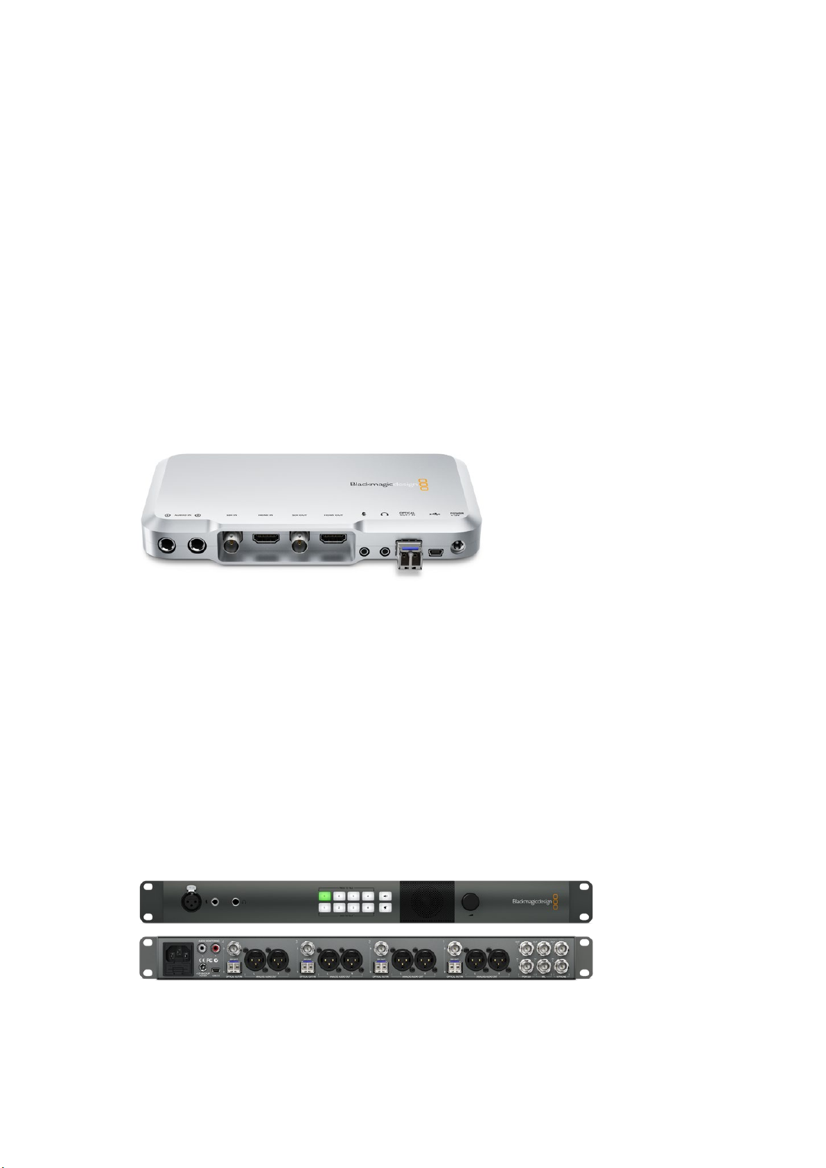
ATEM Camera Converter
ATEM Camera Converter is a portable converter that connects to any SDI or HDMI camera.
The ATEM Camera Converter sends video, audio, tally and talkback signals via bi-directional
optical fiber between itself and a remote unit, for example an ATEM Studio Converter, which
then sends the signal to a switcher. ATEM Camera Converter supports SD, HD and 3G-SDI
formats and can be powered using the internal rechargeable battery or by using mains power.
When paired with another ATEM Camera Converter, ATEM Studio Converter or ATEM Talkback
Converter 4K you get a complete talkback solution for live production. Tally lights are also
enabled when connected to ATEM switchers.
ATEM Camera Converter.
ATEM Studio Converter
ATEM Studio Converter can be partnered with ATEM Camera Converters via optical fiber for
talkback support with any SDI or HDMI cameras. This lets you convert up to 4 cameras to
optical fiber SDI when you need to run video over long cable lengths.
Single mode optical fiber cable with LC connectors are used to connect
ATEM Camera Converter to ATEM Studio Converter. If you are using Blackmagic Studio
Cameras, you can plug your video in directly via optical fiber. The SDI connections, including
the fiber optic inputs, support SD, HD and 6G-SDI video.
You can easily connect your camera audio outputs to an external mixing desk by plugging into
the balanced XLR analog outputs on the ATEM Studio Converter’s rear panel.
When more than 4 cameras are required, you can loop multiple ATEM Studio Converters and
ATEM Talkback Converter 4Ks together.
ATEM Studio Converter.
5Getting Started
Page 6
ATEM Talkback Converter 4K
PTTPGM
VIDEOOPTICAL
PTTPGM
VIDEOOPTICAL
ATEM Talkback Converter 4K is used to connect up to 8 cameras to a switcher via coaxial cable
up to 12G-SDI. When connected to an ATEM switcher you also get tally, plus you can also
connect to ATEM Camera Converters via optical fiber to add talkback.
Blackmagic Studio Camera can connect to your ATEM Talkback Converter 4K via BNC or
optional optical fiber modules. You also get talkback and tally when connected to an
ATEMswitcher.
If you need to connect more cameras, additional ATEM Talkback Converter 4Ks can be looped
together. ATEM Talkback Converter 4K supports SD, HD and Ultra HD video up to 2160p60.
ATEM Talkback Converter 4K with 8 optional SFP modules installed.
Connecting ATEM Camera Converter
The first thing you’ll want to do is power your ATEM Camera Converter, plug in your camera,
headset and a monitor.
Plugging in your Power
ATEM Camera Converter features both an internal rechargeable battery which gives you
mobility in the field, and a connector for plugging in the power adaptor supplied with
ATEMCamera Converter. ATEM Camera Converter’s power connector supports an input range
of 12V to 31V so you can even use an external camera battery. The internal battery will charge
when a power source is connected.
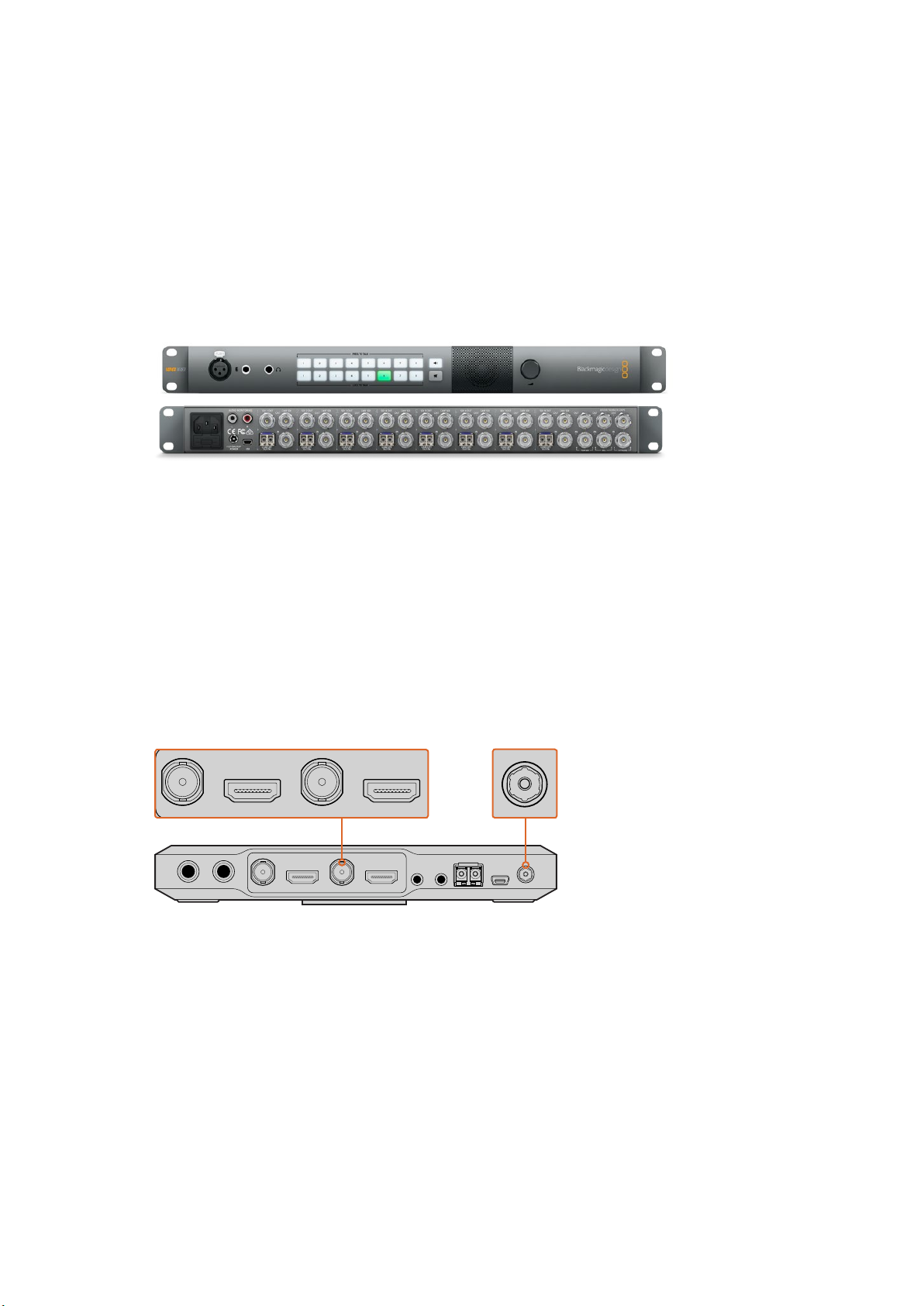
Plug in your power source and charge the internal battery via the 12V to
31V power connector. Connect your camera via the SDI or HDMI input,
and your monitor via the SDI or HDMI output. Bydefault, ATEM Camera
Converter uses embedded SDI or HDMI audio from your camera.
Plugging in your Camera
Plug your camera into your ATEM Camera Converter’s HDMI or SDI connector.
Make sure your camera output is set to a format supported by your live production switcher.
Ifyou’re connecting to an ATEM switcher, check the switcher video standard and then set the
camera to the same video standard, e.g., 1080i59.94.
6Getting Started
Page 7
Plugging in your Headset
PTTPGM
VIDEOOPTICAL
PTTPGM
PTTPGM
VIDEOOPTICAL
PTTPGM
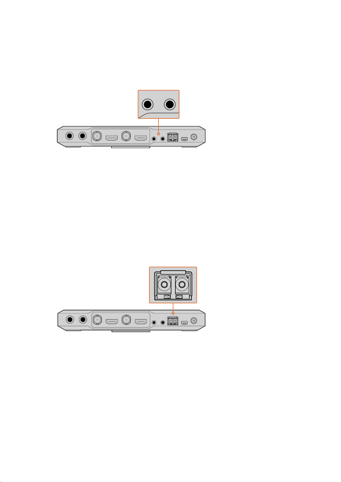
Plug your talkback headset into ATEM Camera Converter’s standard 3.5mm stereo analog
microphone and headphone inputs. An iPhone or Android compatible headset can be
connected using only the headphone jack. However, if you have an external microphone
connected at the same time, only the external microphone will be used.
Connect your headset to ATEM Camera Converter via the standard
3.5mm headphone output and microphone input.
Plugging in your Monitor
Plug your monitor into ATEM Camera Converter’s SDI or HDMI output. Using a monitor lets you
view the camera output or the program output from a switcher. If you are connecting to an
ATEM Switcher, you’ll need to set the camera number on your ATEM Camera Converter so the
tally light will illuminate when the camera is switched to the program output. For more
information, refer to the ‘Using ATEM Camera Converter/Setting the Camera Number’ section.
Connecting via Optical Fiber
You’ll now want to connect your ATEM Camera Converter to either a second Camera Converter,
an ATEM Talkback Converter 4K, or an or ATEM Studio Converter, via duplex single mode
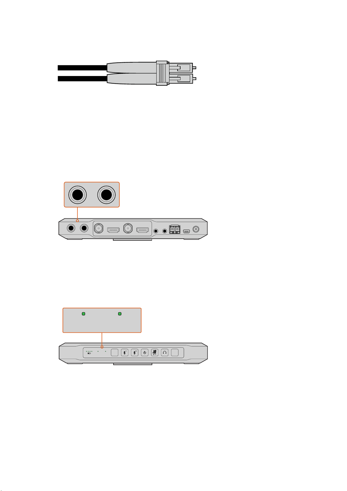
optical fiber cables with LC connectors. A pair of optical fiber cables are typically known as a
patch cord.
ATEM Camera Converter’s optical fiber SFP module.
Plugging in Optical Fiber LC Connectors
To plug optical fiber connectors into your ATEM Converters:
1 Plug one end of the patch cord to your ATEM Camera Converter’s SFP module.
2 Plug the other end of your patch cord to the SFP module on the second
ATEM Camera Converter. If you are connecting multiple cameras to an ATEM Talkback
Converter 4K or ATEM Studio Converter, choose SFP modules appropriate for
each camera.
7Getting Started
Page 8
For example, when connecting camera 1, connect to the camera 1 SFP module.
PTTPGM
VIDEOOPTICAL
PTTPGM
VIDEOOPTICAL
PTTPGM
VIDEOOPTICAL
VIDEOOPTICAL
Optical fiber patch cord with two LC connectors.
Plugging in your Audio
ATEM Camera Converter supports 2 channels of camera audio, which are carried on audio
channels 1 & 2 of the optical fiber SDI connection. By default, ATEM Camera Converter uses the
embedded audio from your camera’s microphone. However, if you want to plug in an external
audio source, connect your audio equipment to ATEM Camera Converter’s two balanced 1/4”
TRS inputs. When external audio is connected it will be used instead of the embedded
camera audio.
The 1/4” TRS connectors accept stereo analog audio at microphone level and are carried on
audio channels 1 & 2 of the optical fiber SDI connection.
Connect external audio equipment to ATEM Camera Converter via TRS connectors.
Confirming Your Video Signal
When your ATEM Camera Converter is powered, a camera is plugged in, and a valid SDI or
HDMI signal is present, you’ll see the control panel ‘video’ status indicator illuminated.
Additionally, if you have your monitor connected and the PGM button set for camera video, your
camera output will be displayed and you’ll know your ATEM Camera Converter is working.
When a valid video signal is detected via SDI or HDMI, you’ll see ATEM Camera
Converter’s ‘video’ status indicator illuminated. The ‘optical’ indicator will illuminate
when a valid SDI signal is detected via the optical fiber input.
Connecting ATEM Studio Converter
The first thing to do is plug in power, plug in your cameras, a headset, and connect to a
switcher. You can also plug in an external microphone, such as a gooseneck microphone if you
want to use talkback without using a headset. You can even output each camera’s audio to a
mixer via balanced analog XLR connectors.
8Getting Started
Page 9
Plugging in Power
4321
OPTICAL OUT/IN
SDI OUT
L R
RL
USB 2.0
+12V BACKUP
POWER
OPTICAL OUT/IN
SDI OUT
L R
ANALOG AUDIO OUT OPTICAL OUT/IN
SDI OUT
L R
ANALOG AUDIO OUT OPTICAL OUT/IN
SDI OUT
L
OUT
R
ANALOG AUDIO OUTANALOG AUDIO OUT
IN
PGM SDI
OUT
IN
MIC
OUT
IN
H/PHONE
AES/EBU TALKBACK LOOPS
PUSH
LOCK TO TALK
PRESS TO TALK
4321
OPTICAL OUT/IN
SDI OUT
L R
RL
USB 2.0
+12V BACKUP
POWER
OPTICAL OUT/IN
SDI OUT
L R
ANALOG AUDIO OUT OPTICAL OUT/IN
SDI OUT
L R
ANALOG AUDIO OUT OPTICAL OUT/IN
SDI OUT
L
PUSH
LOCK TO TALK
PRESS TO TALK
4321
OPTICAL OUT/IN
SDI OUT
L R
RL
USB 2.0
+12V BACKUP
POWER
OPTICAL OUT/IN
SDI OUT
L R
ANALOG AUDIO OUT OPTICAL OUT/IN
SDI OUT
L R
ANALOG AUDIO OUT OPTICAL OUT/IN
SDI OUT
L
OUT
R
ANALOG AUDIO OUTANALOG AUDIO OUT
IN
PGM SDI
OUT
IN
MIC
OUT
IN
H/PHONE
AES/EBU TALKBACK LOOPS
PUSH
LOCK TO TALK
PRESS TO TALK
OPTICAL OUT/IN
SDI OUT
L R
OPTICAL OUT/IN
SDI OUT
L R
ANALOG AUDIO OUT OPTICAL OUT/IN
SDI OUT
LOCK TO TALK
PRESS TO TALK
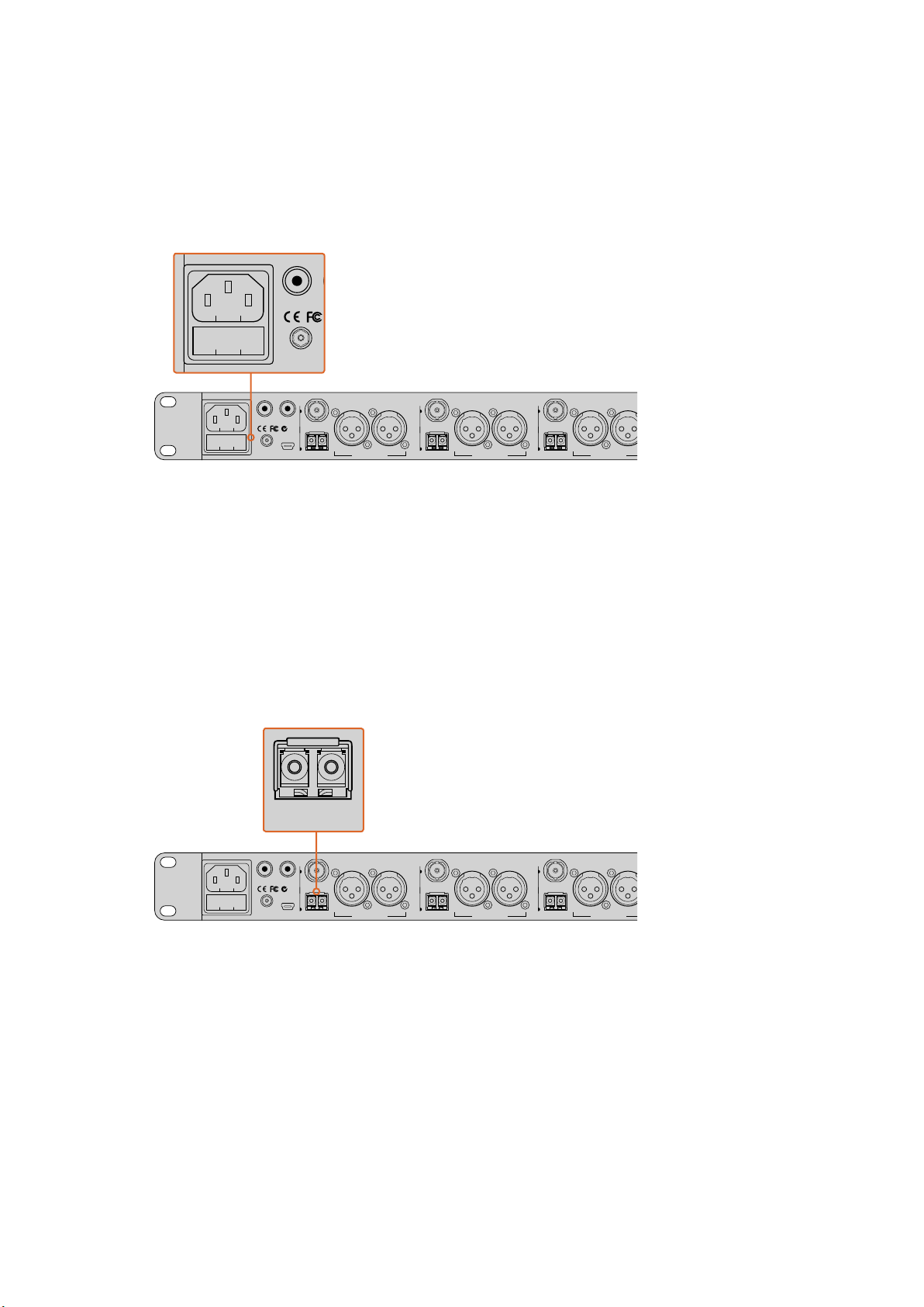
Plug in your power via your ATEM Converter’s mains power input using a standard IEC cable.
You can also connect a power adaptor or external camera battery to the 12V to 31V power input.
2 power inputs give you the option of a redundant power connection in case one supply fails or
is accidentally disconnected.
Plug in power via the mains power, or the 12V or 31V power connector.
Plugging in Cameras
On the back panel of your ATEM Studio Converter, you’ll see 4 groups of connectors
numbered 1 to 4.
1 Plug your cameras into each optical fiber SFP module.
2 The second LC connector plugged into the SFP module is used to connect the program
video back to your Blackmagic Studio Camera or ATEM Camera Converter.
3 Plug each camera SDI output from your ATEM Studio Converter to the corresponding
camera inputs in your switcher.
Plug your cameras into ATEM Studio Converter’s optical fiber inputs.
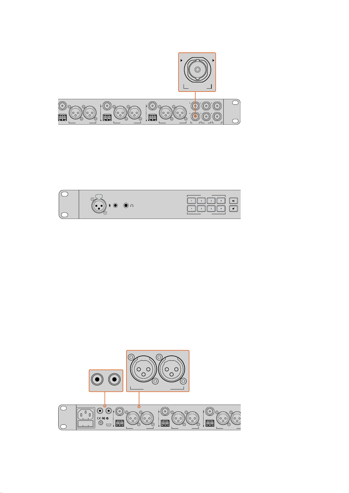
Plugging in the Program Feed from your Switcher
Connect the program output from your switcher to your ATEM Studio Converter’s ‘PGM SDI in’
connector. When connecting the program output from an ATEM switcher, tally is also
embedded in the SDI signal. This will enable tally lights when connected to
ATEM Camera Converters via optical fiber and Blackmagic Studio Cameras.
9Getting Started
Page 10
4321
SDI OUT
L R
ANALOG AUDIO OUT OPTICAL OUT/IN
SDI OUT
L R
ANALOG AUDIO OUT OPTICAL OUT/IN
SDI OUT
L
OUT
R
ANALOG AUDIO OUTANALOG AUDIO OUT
IN
PGM SDI
OUT
IN
MIC
OUT
IN
H/PHONE
AES/EBU TALKBACK LOOPS
LOCK TO TALK
PRESS TO TALK
IN
PGM SDI
OUT
IN
MIC
OUT
IN
H/PHONE
AES/EBU TALKBACK LOOPS
Plug the program SDI output from your switcher into your ATEM Studio Converter’s ‘PGM SDI’ input.
PUSH
LOCK TO TALK
PRESS TO TALK
4321
OPTICAL OUT/IN
SDI OUT
L R
RL
USB 2.0
+12V BACKUP
POWER
OPTICAL OUT/IN
SDI OUT
L R
ANALOG AUDIO OUT OPTICAL OUT/IN
SDI OUT
L R
ANALOG AUDIO OUT OPTICAL OUT/IN
SDI OUT
L
OUT
R
ANALOG AUDIO OUTANALOG AUDIO OUT
IN
PGM SDI
OUT
IN
MIC
OUT
IN
H/PHONE
AES/EBU TALKBACK LOOPS
PUSH
LOCK TO TALK
PRESS TO TALK
4321
RL
LOCK TO TALK
PRESS TO TALK
4321
L R
ANALOG AUDIO OUT OPTICAL OUT/IN
SDI OUT
L
OUT
R
ANALOG AUDIO OUTANALOG AUDIO OUT
IN
PGM SDI
OUT
IN
MIC
OUT
IN
H/PHONE
AES/EBU TALKBACK LOOPS
Plugging in your Headset
Your ATEM Studio Converter uses aviation headsets that plug in via the 1/4” TRS headphone
and 0.206” microphone jacks. If both a headset and an external microphone are plugged in,
only the headset will be used. Talkback audio is embedded into audio channels 15 & 16 of the
SDI signal.
Connect your aviation headset via your ATEM Studio Converter front panel TRS connectors.
You can also plug in an external microphone via the balanced XLR analog input.
Plugging in your External Microphone
If you want to use an external microphone, plug in via the balanced XLR analog input on your
ATEM Studio Converter’s front control panel.
Outputting Camera Audio
You can easily connect your camera audio outputs to an external mixing desk by plugging into
the balanced XLR analog outputs on the rear panel.
Monitoring your Audio
If you want to monitor your program or talkback audio on external audio equipment such as
a Blackmagic Audio Monitor, connect via the RCA outputs on your ATEM Studio Converter’s
rear panel. Plus, you can easily connect your camera’s audio to a mixer using the XLR analog
audio outputs.
Monitor your program or talkback audio on external equipment by
connecting to ATEM Studio Converter’s RCA outputs.
10Getting Started
Page 11
Connecting ATEM Talkback Converter 4K
PGM SDI MIC H/PHONE
SDI 1 OUT CAM SDI
CAM OPT
OUT/IN
SDI 2 OUT CAM SDI
CAM OPT
OUT/IN
SDI 2 OUT CAM SDI
CAM OPT
OUT/IN
SDI 4 OUT CAM SDI
CAM OPT
OUT/IN
SDI 5 OUT CAM SDI
CAM OPT
OUT/IN
SDI 6 OUT CAM SDI
CAM OPT
OUT/IN
SDI 7 OUT CAM SDI
CAM OPT
OUT/IN
SDI 8 OUT CAM SDI
CAM OPT
OUT/IN
SDI 1 OUT CAM SDI
CAM OPT
OUT/IN
SDI 2 OUT CAM SDI
CAM OPT
OUT/IN
SDI 2 OUT CAM SDI
CAM OPT
OUT/IN
SDI 4 OUT CAM SDI
CAM OPT
OUT/IN
SDI 5 OUT CAM SDI
CAM OPT
OUT/IN
SDI 6 OUT CAM SDI
CAM OPT
OUT/IN
SDI 7 OUT CAM SDI
CAM OPT
OUT/IN
PGM SDI MIC H/PHONE
SDI 1 OUT CAM SDI
CAM OPT
OUT/IN
SDI 2 OUT CAM SDI
CAM OPT
OUT/IN
SDI 2 OUT CAM SDI
CAM OPT
OUT/IN
SDI 4 OUT CAM SDI
CAM OPT
OUT/IN
SDI 5 OUT CAM SDI
CAM OPT
OUT/IN
SDI 6 OUT CAM SDI
CAM OPT
OUT/IN
SDI 7 OUT CAM SDI
CAM OPT
OUT/IN
SDI 8 OUT CAM SDI
CAM OPT
OUT/IN
SDI 1 OUT CAM SDI
SDI 2 OUT CAM SDI
SDI 2 OUT CAM SDI
SDI 4 OUT CAM SDI
SDI 5 OUT CAM SDI
SDI 2 OUT CAM SDI
CAM OPT
OUT/IN
SDI 2 OUT CAM SDI
CAM OPT
OUT/IN
SDI 4 OUT CAM SDI
CAM OPT
OUT/IN
SDI 5 OUT CAM SDI
CAM OPT
OUT/IN
The first thing to do is plug in power, your cameras, a headset and connect to a switcher. You
can also plug in an external microphone, such as a gooseneck microphone if you want to use
talkback without using a headset.
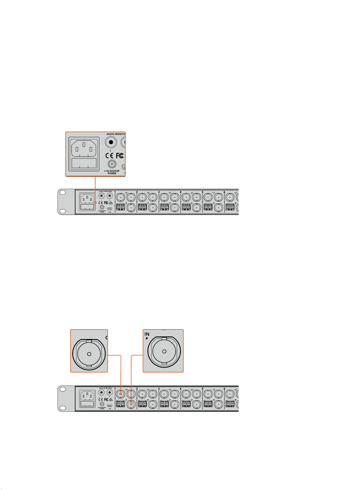
Plugging in Power
Plug in your power via your ATEM Talkback Converter 4K’s mains power input using a standard
IEC cable. You can also connect a power adaptor or external camera battery to the 12V to 31V
power input. 2 power inputs give you the option of a redundant power connection in case one
supply fails or is accidentally disconnected.
Plug in power via the mains power, or the 12V or 31V power connector.
Plugging in Cameras
On the back panel of your ATEM Talkback Converter 4K, you’ll see 8 groups of connectors that
are assigned to camera numbers 1 to 8.
1 Plug your cameras into each ‘Cam SDI in’ connector.
2 Plug your ATEM Talkback Converter 4K’s ‘Cam SDI out’ into your camera’s program
SDI input.
When using ATEM Camera Converters with ATEM Talkback Converter 4K, it is important
to note that talkback and tally are embedded in the SDI signal via optical fiber only.
3 Plug the numbered SDI outputs, for example ‘SDI 1 Out’, to the corresponding camera
inputs in your switcher.
Plug your cameras into ATEM Talkback Converter 4K’s camera SDI inputs. When optical fiber
SFP modules are installed, you can also plug cameras into your ATEM Talkback Converter 4K
via optical fiber. Plug your ATEM Talkback Converter 4K’s ‘SDI out’ into your switcher.
11Getting Started
Page 12
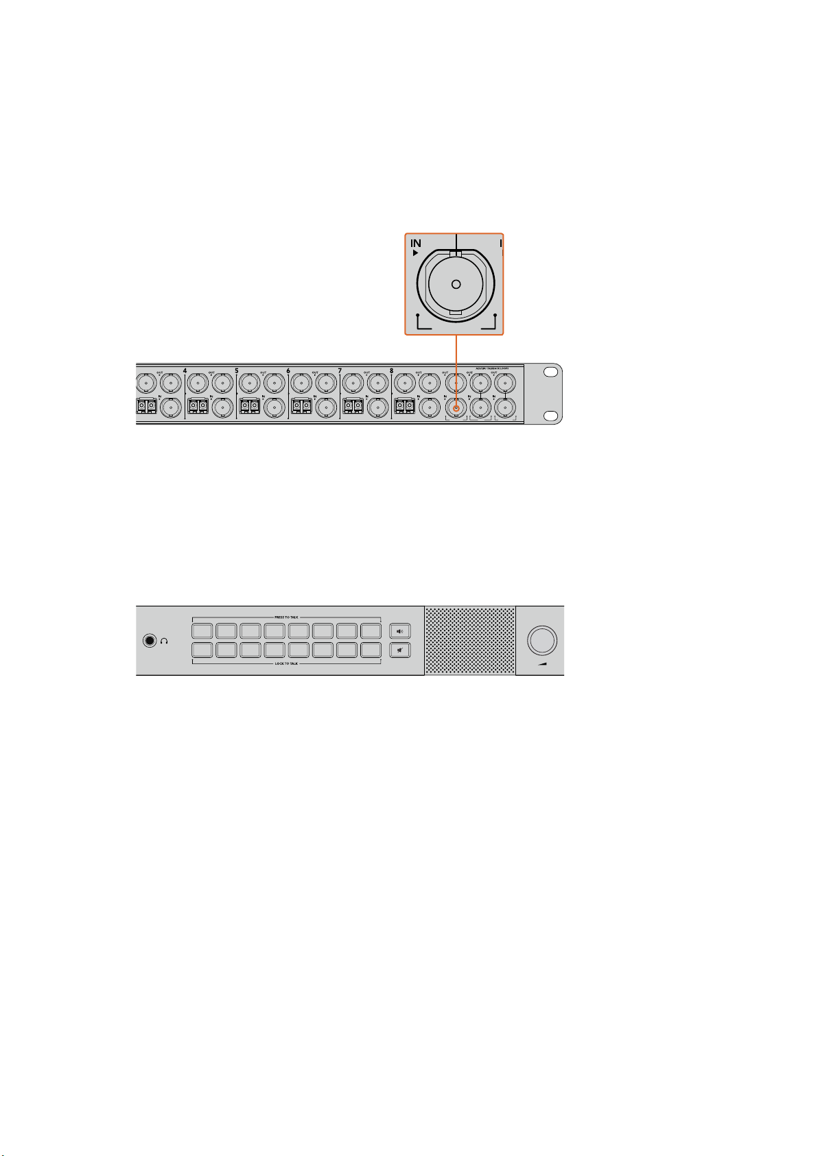
Plugging in the Program Feed from your Switcher
PGM SDI MIC H/PHONE
SDI 2 OUT CAM SDI
CAM OPT
OUT/IN
SDI 4 OUT CAM SDI
CAM OPT
OUT/IN
SDI 5 OUT CAM SDI
CAM OPT
OUT/IN
SDI 6 OUT CAM SDI
CAM OPT
OUT/IN
SDI 7 OUT CAM SDI
CAM OPT
OUT/IN
SDI 8 OUT CAM SDI
CAM OPT
OUT/IN
PGM SDI MIC H/PHONE
1 2 3 4 5 6 7 8
1 2 3 4 5 6 7 8
Connect the program output from your switcher to your ATEM Talkback Converter 4K’s
‘PGMSDI in’ connector. When connecting the program output from an ATEM switcher, tally is
also embedded in the SDI signal. This will enable tally lights when connected to
ATEM Camera Converters, Blackmagic Studio Cameras and Blackmagic URSA
Broadcast Cameras.
Plug the program SDI output from your switcher into your
ATEM Talkback Converter 4K’s ‘PGM SDI’ input.
Plugging in your Headset
Your ATEM Talkback Converter 4K uses aviation headsets that plug in via the 1/4” TRS
headphone and 0.206” microphone jacks.
If both a headset and an external microphone are plugged in, only the headset will be used.
Talkback audio is embedded into audio channels 15 & 16 of the SDI signal.
Connect your aviation headset via your ATEM Talkback Converter 4K front panel TRS connectors. You can also
plug in an external microphone via the balanced XLR analog input if you want to use talkback without a headset.
Plugging in your External Microphone
If you want to use an external microphone, plug in via the balanced XLR analog input on your
ATEM Converter’s front control panel.
Monitoring your Audio
If you want to monitor your program or talkback audio on external audio equipment such as a
Blackmagic Audio Monitor, connect via the RCA outputs on your ATEM Talkback Converter 4K
or ATEM Studio Converter’s rear panel.
Confirming your ATEM Converter Set Up
After connecting your ATEM Converters to a live production switcher you’ll want to confirm that
everything is working.
The first thing to do is check the switcher is getting a valid signal from your cameras. You can
check this by having the switcher operator switch each camera to the preview or program
output. If all your camera signals can be seen on the switcher’s preview or program output,
you’ll know your ATEM Converters are working.
12Getting Started
Page 13
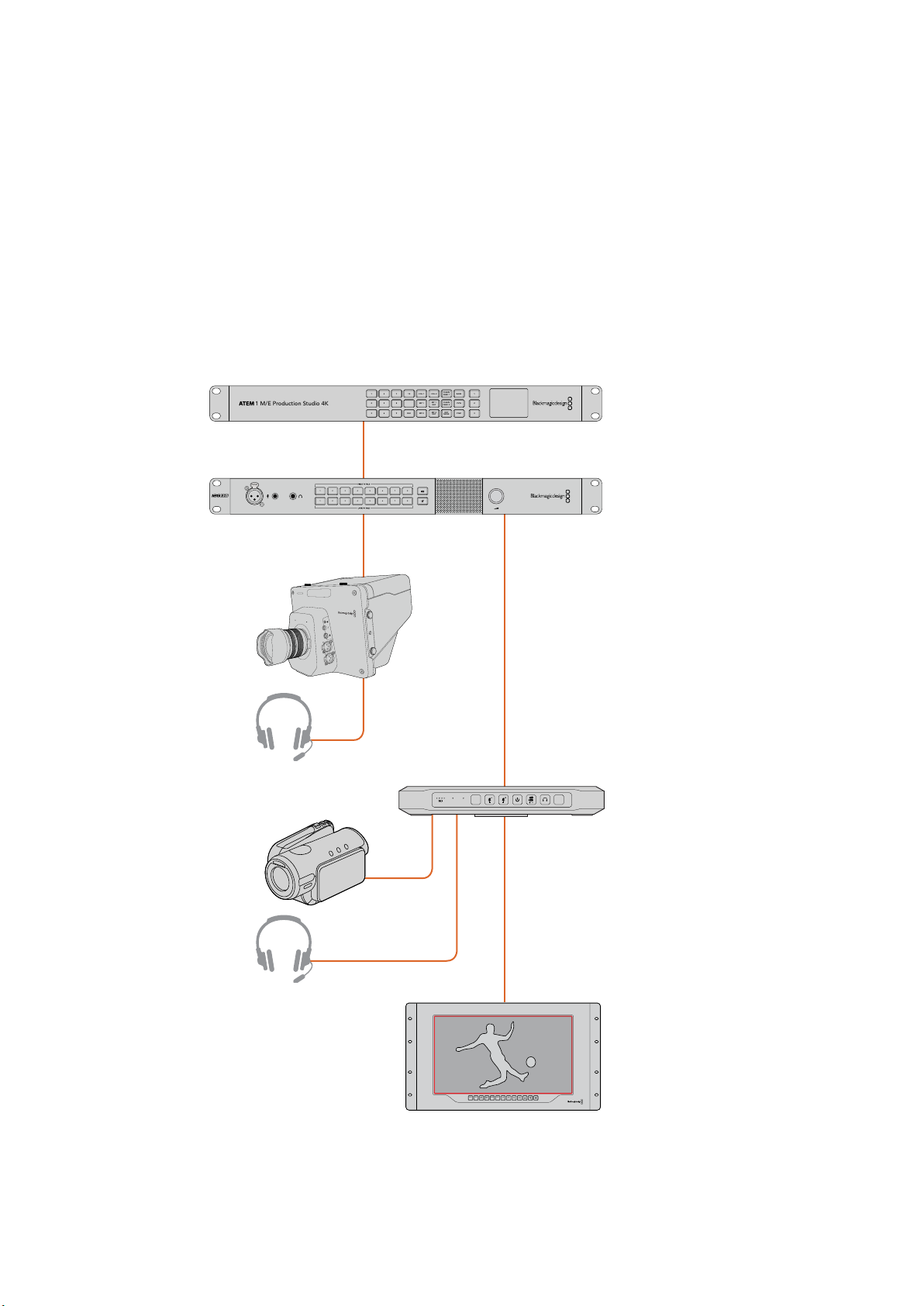
Next, check your talkback. Have the switcher operator and camera operators speak to each
INPUT DISP
H/V
DELAY3DLUT 1
BLUE
ONLY
ZOOM PEAK
3D
LUT 2HMARKVMARK
1
1
3
PUSH
2
2
1
3
PUSH
2
1 4 7 10 COL 1 COL 2
CLEAN
FEED 1
BARS 1
2 5 8 MP 1
CLEAN
FEED 2
MP 1
KEY
PVW 2
3 6 9 BLK MP 2
KEY
MASK
MP 2
KEY
PGM 3
1 M/E Production Studio 4K
PUSH
1 2 3 4 5 6 7 8
1 2 3 4 5 6 7 8
other using their ‘press to talk’ buttons and headsets.
If you are using an ATEM switcher, tally signals are sent over the SDI connection. To make sure
tally is working, check the camera number on ATEM Camera Converters and make sure they
match the camera numbers on the ATEM switcher. For more information, refer to the ‘Using
ATEM Camera Converter/Setting the Camera number’ section of this manual.
If you experience any trouble setting up your ATEM Converters, please visit the
Blackmagic Design support center at www.blackmagicdesign.com/support where you can often
find answers quickly by browsing the Blackmagic Forum. Here you can read information and
comments from other experienced users and Blackmagic Design staff. You can also find
contact information for your local Blackmagic Design support team.
ATEM 1 M/E Produc tion Studio 4K
ATEM Talkback Converter 4K
Blackmagic Studio
Camera
HDMI Camera
VIDEOOPTICAL
PTTPGM
ATEM Camera
Converter
Monitor
Refer to the ‘Connection Diagrams’ section for more information on how to connect your ATEM Converters.
13Getting Started
Page 14
Using ATEM Camera Converter
PTTPGM
VIDEOOPTICAL
PTTPGM
VIDEOOPTICAL
Front Control Panel
ATEM Camera Converter’s control panel features buttons for adjusting headset and microphone
volume, activating talkback, program/camera monitoring, powering on and off, and setting the
camera number. There are also 5 status indicators for battery level, optical signal, SDI or HDMI
signal, and tally.
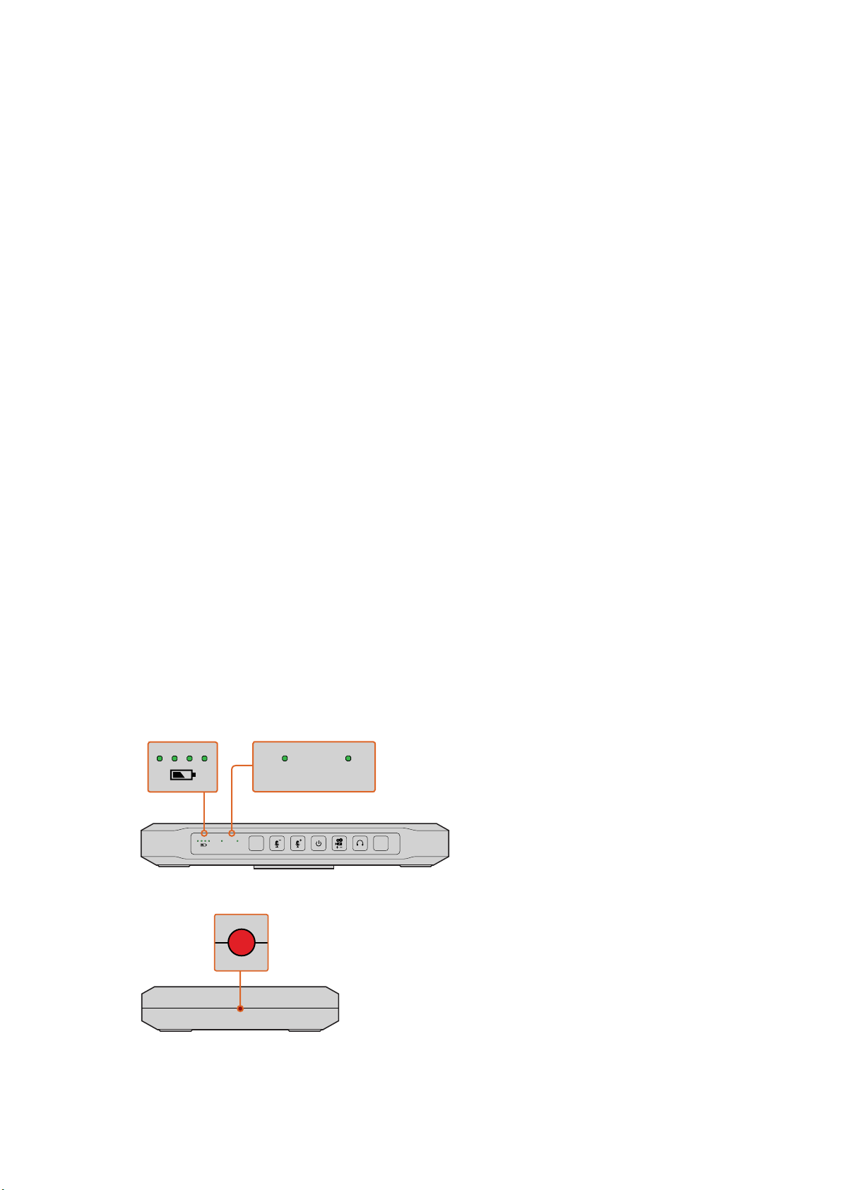
Status Indicators
Battery level
On the far left of the control panel are four green battery level indicators. The number of
illuminated indicators decrease as the battery level decreases. When the remaining single
indicator starts flashing, there’s approximately 10 minutes of battery power left, so you should
plug in an external power source or switch to another charged ATEM Camera Converter. The
battery will last for over 2 hours of continuous use and requires approximately 8 hours for a
complete recharge.
Optical
Next to the battery level LEDs is the ‘optical’ indicator. This lights up when an optical fiber SDI
video signal is detected by ATEM Camera Converter. Use this indicator to confirm a valid optical
SDI signal is being sent or received.
Video
The ‘video’ indicator lights up when a valid SDI or HDMI video signal is detected by
ATEM Camera Converter. Use this indicator to confirm that your camera input signal is present.
Tally lights
These lights illuminate when a tally signal is received from the program output of an
ATEM switcher. By watching the two red tally lights on opposite sides of
ATEM Camera Converter, your talent and camera operator can see when they are on air.
VIDEOOPTICAL
Battery level, optical, and video signal status indicators.
PTTPGM
The tally lights on each side of the ATEM Camera Converter glow red
when your camera is live on the program output of an ATEM switcher.
14Using ATEM Camera Converter
Page 15
Control Panel Buttons
PTTPGM
VIDEOOPTICAL
PTTPGM
PTTPGM
VIDEOOPTICAL
PTTPGM
PTTPGM
PGM
Pressing the PGM button toggles between the program video signal and the camera input
signal. The program input is the signal connected via optical fiber.
PGM button and microphone volume level buttons.
The buttons will illuminate when pressed or activated.
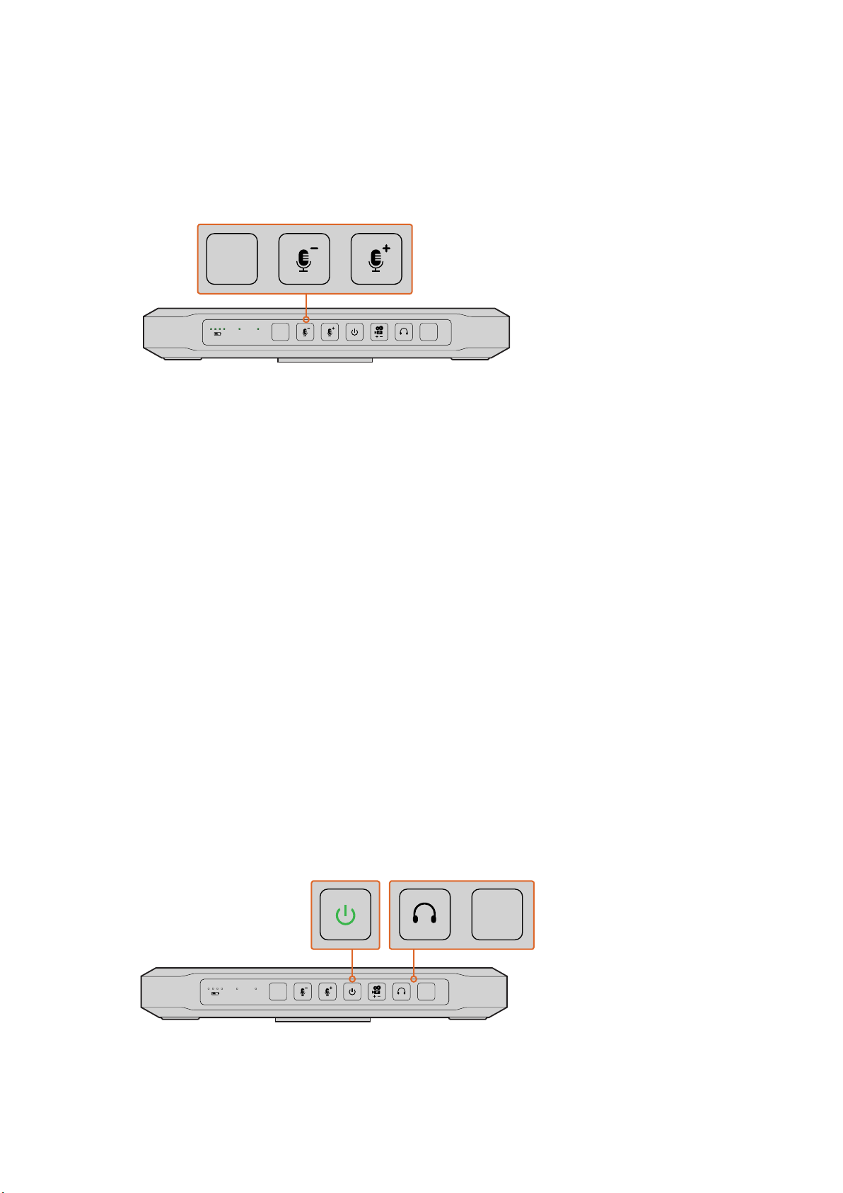
Microphone Volume Down/Up
The microphone volume buttons provide a quick way to adjust external audio levels. Each press
of the microphone volume buttons provide a smooth increase or decrease in volume over 1
second. When maximum or minimum microphone volume is reached, or if at maximum or
minimum volume at power up, the relevant button will illuminate for 3 seconds. These buttons
do not affect embedded SDI and HDMI audio levels received directly from the camera.
Power On/O
Press and release to instantly power on. Hold for 1 second to power off.
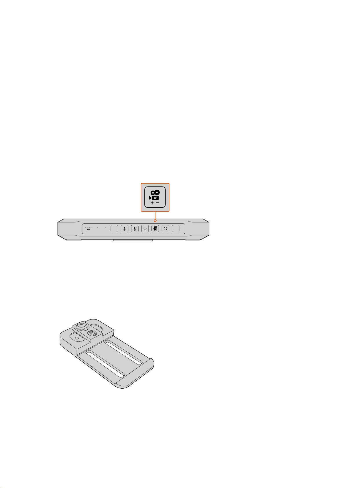
Camera Number
This button is used to set the camera number on your ATEM Camera Converter so your tally
lights function correctly. Refer to the ‘setting the camera number’ section in this manual for a
detailed description.
Talkback Headphone Volume
Press this button to increase the volume of the talkback headphones. When maximum volume
is reached, or if at maximum volume at power up, the button will illuminate for 3 seconds. The
next press will reduce the volume to minimum before the volume is increased again.
PTT
Press to talk allows camera operators to talk to the switcher operator. Hold the button down
while talking. If the PTT button is pressed twice in quick succession, it will stay on to allow
hands free communication. If PTT is pressed again, it will revert to normal press to talk behavior.
The power button will illuminate when ATEM Camera Converter is powered
on. Press the PTT button to engage talkback with another ATEM Camera
Converter, ATEM Talkback Converter 4K, or ATEM Studio Converter.
Press thetalkback headphone button to adjust the talkback volume.
15Using ATEM Camera Converter
Page 16
Setting the Camera Number
PTTPGM
VIDEOOPTICAL
PTTPGM
If you want your ATEM Camera Converter to receive tally signals from an ATEM switcher, you’ll
need to set the camera number on your ATEM Camera Converter. This ensures the switcher
sends the tally signal to the correct ATEM Camera Converter. The camera number can be set
from 1 to 99.
To set the camera number with the camera number button, press and hold the button until its
button light flashes 3 times. This will reset the camera number to camera 1. Each subsequent
press of the button will increment the camera number by 1. For example, if you want to set your
ATEM Camera Converter to camera number 5, reset the camera number to 1 and then add 4
button presses.
To test if camera number 5 is set correctly, have the ATEM switcher operator switch camera
number 5 to the program output. If your camera number is set correctly, the tally lights will
illuminate on your ATEM Camera Converter.
Similarly, if you want to test what camera number your ATEM Camera Converter is set to, ask the
ATEM switcher operator to switch camera inputs to the program output until your tally lights
illuminate. The switcher operator can then confirm your camera number.
‘Camera number’ button.
Mounting ATEM Camera Converter
When your camera needs to be mobile, connect your cables to ATEM Camera Converter and
then snap the integrated belt clip on to your belt. For stationary shots, ATEM Camera Converter
can be mounted on a tripod arm with either of its standard 3/8” or 1/4” thread inserts. If you want
to sit ATEM Camera Converter on a desk using its rubber feet, undo the two 2.5 hex socket
screws and remove the belt clip.
ATEM Camera Converter can be clipped
to your belt, mounted on a tripod arm, or
placed on its rubber feet on a desk.
16Using ATEM Camera Converter
Page 17
Using ATEM Studio Converter
LOCK TO TALK
PRESS TO TALK
LOCK TO TALK
PRESS TO TALK
LOCK TO TALK
PRESS TO TALK
Front Control Panel
Your ATEM Studio Converter’s control panel features two rows of talkback buttons, including
‘PTT’ and ‘LTT’, or, ‘press to talk’ and ‘lock to talk’, for each of the camera inputs. Next to the
talkback buttons are PGM
change to green when selected.
PTT 1-4 — The ‘press to talk’ buttons let you communicate with each camera operator
independently. The PTT button illuminates green and activates your external or headset
microphone while the button is pressed.
LTT 1-4 — The ‘lock to talk’ buttons lock your external or headset microphone open until you
press them again. You can even lock your microphone open for all cameras if you want to
communicate with all camera operators simultaneously. Cameras can be communicated with
independently using PTT even if all LTT buttons are selected.
and Mute buttons. All buttons are illuminated white and
PGM
Pressing the program button enables program audio with talkback. When a camera
operator uses talkback, your ATEM Studio Converter’s program audio level is decreased so
talkback can be heard clearly. When PGM is deselected only talkback audio is heard.
Mute
Pressing the ‘mute’ button will quickly fade the built in speaker to silence. Pressing
mute again, or increasing the volume, will restore audio. This button only affects the speaker
output and will not affect your program or talkback audio output.
Built in Speaker and Volume Control — You can hear program audio and talkback via the
control panel speaker, or with headphones via the 1/4” TRS headphones input. Adjust the
volume for the speaker or headphones by turning the volume knob on the control panel
clockwise or counterclockwise.
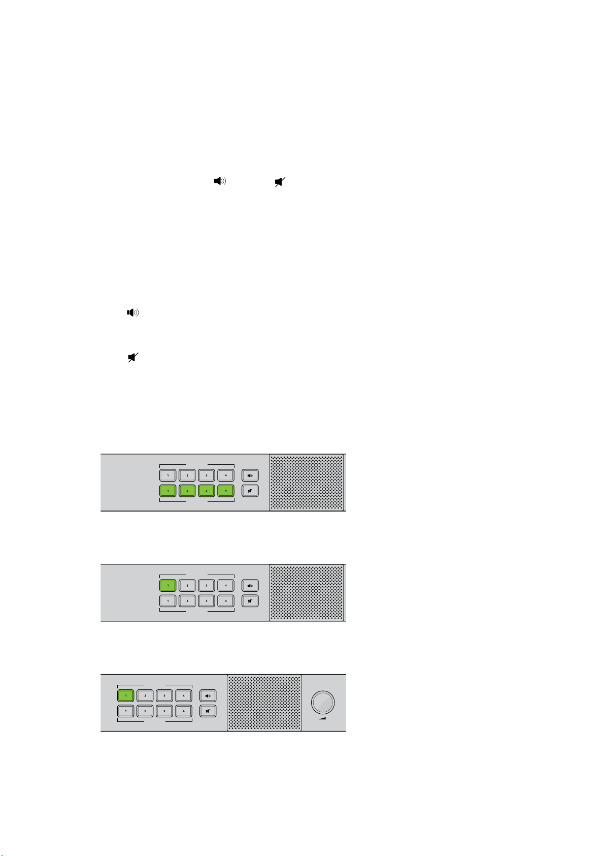
ATEM Studio Converter’s control panel buttons are used for talkback,
enabling or disabling program audio, and muting the speaker.
The above illustration shows all the LTT buttons activated.
You can communicate with a single camera operator
even when LTT is selected for all cameras. All LTT
buttons are deactivated while PTT is pressed.
Volume is easily adjusted by turning the volume
control clockwise and anticlockwise.
17Using ATEM Studio Converter
Page 18
Using ATEM Talkback Converter 4K
5
Front Control Panel
Your ATEM Talkback Converter 4K’s control panel features two rows of talkback buttons,
including ‘PTT’ and ‘LTT’, or, ‘press to talk’ and ‘lock to talk’, for each of the camera inputs.
Next to the talkback buttons are PGM
white and change to green when selected.
PTT 1-8 — The ‘press to talk’ buttons let you communicate with each camera operator
independently. The PTT button illuminates green and activates your external or headset
microphone while the button is pressed.
LTT 1-8 — The ‘lock to talk’ buttons lock your external or headset microphone open until you
press them again. You can even lock your microphone open for all cameras if you want to
communicate with all camera operators simultaneously. Cameras can be communicated with
independently using PTT even if all LTT buttons are selected.
and Mute buttons. All buttons are illuminated
PGM
Pressing the program button enables program audio with talkback. When a camera
operator uses talkback, your ATEM Talkback Converter 4K’s program audio level is decreased
so talkback can be heard clearly. When PGM is deselected only talkback audio is heard.
Mute
Pressing the ‘mute’ button will quickly fade the built in speaker to silence. Pressing
mute again, or increasing the volume, will restore audio. This button only affects the speaker
output and will not affect your program or talkback audio output.
Built in Speaker and Volume Control — You can hear program audio and talkback via the
control panel speaker, or with headphones via the 1/4” TRS headphones input. Adjust the
volume for the speaker or headphones by turning the volume knob on the control panel
clockwise or counterclockwise.
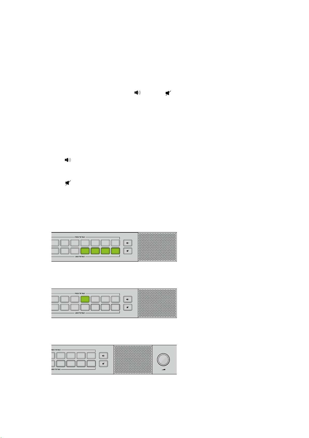
ATEM Talkback Converter 4K’s control panel buttons are used for
talkback, enabling or disabling program audio, and muting the speaker.
The above illustration shows LTT buttons 5, 6, 7 and 8 activated.
You can communicate with a single camera operator
even when LTT is selected for all cameras. All LTT
buttons are deactivated while PTT is pressed.
Volume is easily adjusted by turning the volume
control clockwise and anticlockwise.
18Using ATEM Talkback Converter 4K
Page 19
Using Blackmagic Converters Setup
Blackmagic Converters Setup is used to configure settings and update the internal software in
your ATEM Camera Converter, ATEM Talkback Converter 4K or ATEM Studio Converter.
Installing Blackmagic Converters Setup
The Blackmagic Converters utility software can be used to update your converter to new video
standards, add compatibility with new hardware or adjust video and audio levels.
Installation on Mac OS X
1 Download the Blackmagic Converters Setup software from www.blackmagicdesign.com
2 Unzip the downloaded file and open the resulting disk image to reveal its contents.
3 Double click the installer and follow the prompts to complete the installation.
4 When the installation has finished, it will prompt you to restart your computer.
Click‘restart’ to complete the installation. Blackmagic Converters Setup is
nowinstalled.
Installation on Windows
1 Download Blackmagic Converters Setup from www.blackmagicdesign.com
2 Unzip the downloaded file. You should see a Blackmagic Converters Setup folder
containing this PDF manual and the Blackmagic Converters Setup installer.
3 Double click the installer and follow the prompts to complete the installation.
4 When the installation has finished, it will prompt you to restart your computer.
Click‘restart’ to complete the installation.
Once the computer has restarted, Blackmagic Converters Setup will be ready to use.
19Using Blackmagic Converters Setup
Page 20
Removing Blackmagic Converters Setup
To remove the Blackmagic Converters software on Mac OS X, launch the Blackmagic
Converters.dmg installation file, double click on ‘Uninstall Converters’ and simply follow
the prompts.
To remove the Blackmagic Converters software on Windows, open the Windows control panel
and click on ‘Programs and Features’. Select ‘Blackmagic Converters’ from the list, click on
‘Uninstall’ and follow the prompts.
Updating your ATEM Converter’s Software
After installing Blackmagic Converters Setup on your computer, connect a USB cable between
the computer and your ATEM Converter. Launch Blackmagic Converters Setup and follow any
onscreen prompt to update the internal software in your ATEM converter. If no prompt appears,
the internal software is up to date and there is nothing further you need to do.
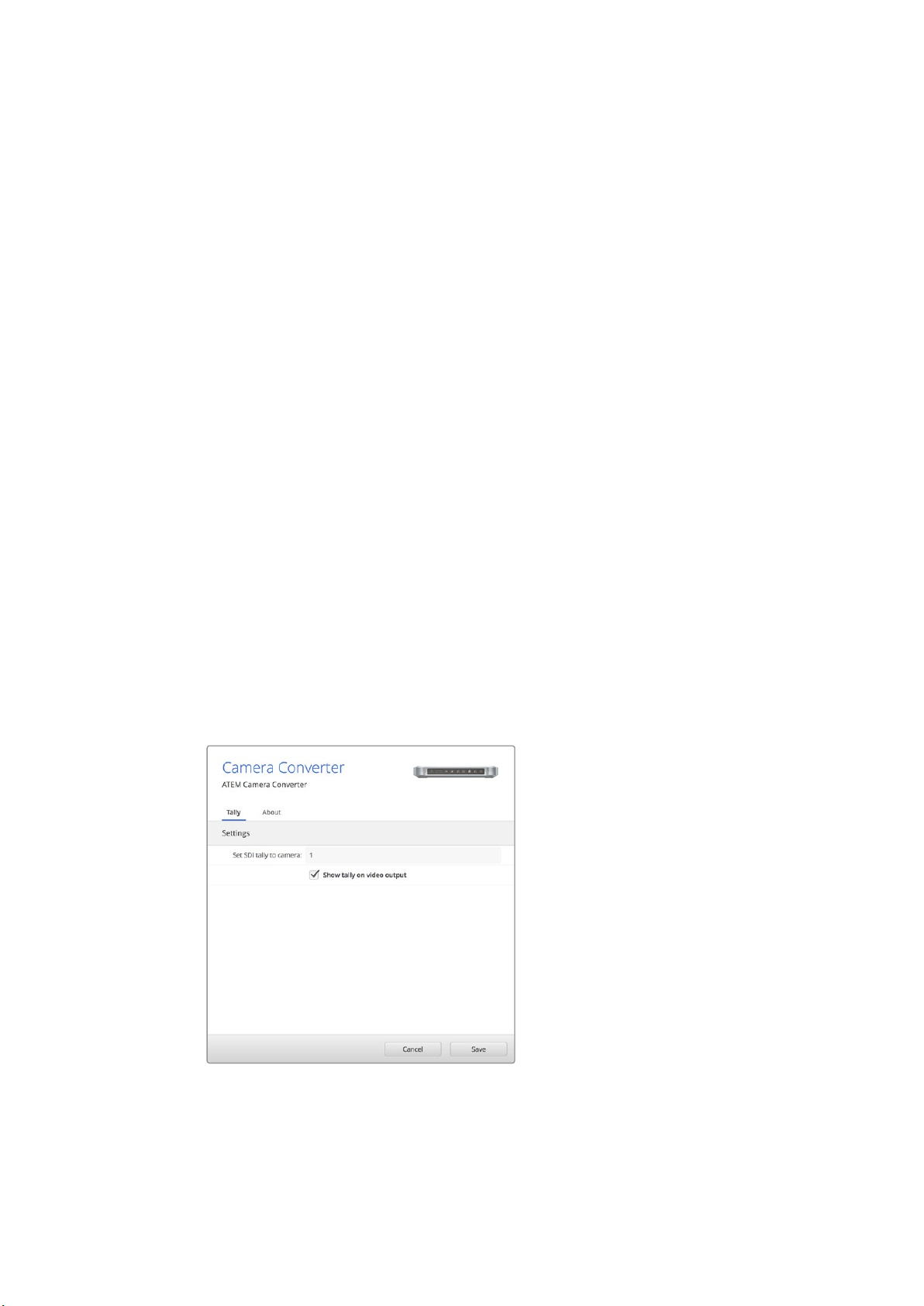
Setting the Tally Border and Camera Number
In addition to tally lights, you can also display a tally border on an SDI or HDMI monitor
connected to your ATEM Camera Converter. This option is set using Blackmagic Converters
Setup, where you can also set the camera number.
1 Connect an ATEM Camera Converter to your computer via USB.
2 Launch Blackmagic Converters Setup, select your ATEM Camera Converter and click
the ‘settings’ tab.
3 Set the camera number and also choose whether to show a tally border on the monitor
attached to the ATEM Camera Converter. Click ‘save’ to confirm your settings and exit
Blackmagic Converters Setup.
If you chose not to display a tally border, the tally lights on the ATEM Camera Converter will still
illuminate when your camera is live on the program output of the ATEM switcher.
You can easily change the ‘camera number’ setting for your ATEM Camera
Converter using Blackmagic Converters Setup. You can also choose
whether or not to display a tally border around your connected monitor by
checking or unchecking the ‘show tally on my video output’ checkbox.
20Using Blackmagic Converters Setup
Page 21
Connection Diagrams
1 7 13 19 COL 1 BARS AUX 1
2 8 14 20 COL 2
SPR
SRC
AUX 2
3 9 15
KEY
MASK
CLEAN
FEED 1
ME 2
PVW
AUX 3
4 10 16 BLK
CLEAN
FEED 2
ME 2
PGM
AUX 4
5 11 17 MP 1 MP 1K
ME 1
PVW
AUX 5
6 12 18 MP 2 MP 2K
ME 1
PGM
AUX 6
1 7 13 19 COL 1 BARS AUX 1
2 8 14 20 COL 2
SPR
SRC
AUX 2
3 9 15
KEY
MASK
CLEAN
FEED 1
ME 2
PVW
AUX 3
4 10 16 BLK
CLEAN
FEED 2
ME 2
PGM
AUX 4
5 11 17 MP 1 MP 1K
ME 1
PVW
AUX 5
6 12 18 MP 2 MP 2K
ME 1
PGM
AUX 6
PTTPGM
VIDEOOPTICAL
PUSHPUSHPUSHPUSH
SDI 1 OUT CAM SDI
SDI 2 OUT CAM SDI
SDI 2 OUT CAM SDI
SDI 4 OUT CAM SDI
SDI 5 OUT CAM SDI
SDI 6 OUT CAM SDI
SDI 7 OUT CAM SDI
SDI 8 OUT CAM SDI
PGM SDI MIC H/PHONE
SDI 1 OUT CAM SDI
CAM OPT
OUT/IN
SDI 2 OUT CAM SDI
CAM OPT
OUT/IN
SDI 2 OUT CAM SDI
CAM OPT
OUT/IN
SDI 4 OUT CAM SDI
CAM OPT
OUT/IN
SDI 5 OUT CAM SDI
CAM OPT
OUT/IN
SDI 6 OUT CAM SDI
CAM OPT
OUT/IN
SDI 7 OUT CAM SDI
CAM OPT
OUT/IN
SDI 8 OUT CAM SDI
CAM OPT
OUT/IN
PGM SDI MIC H/PHONE
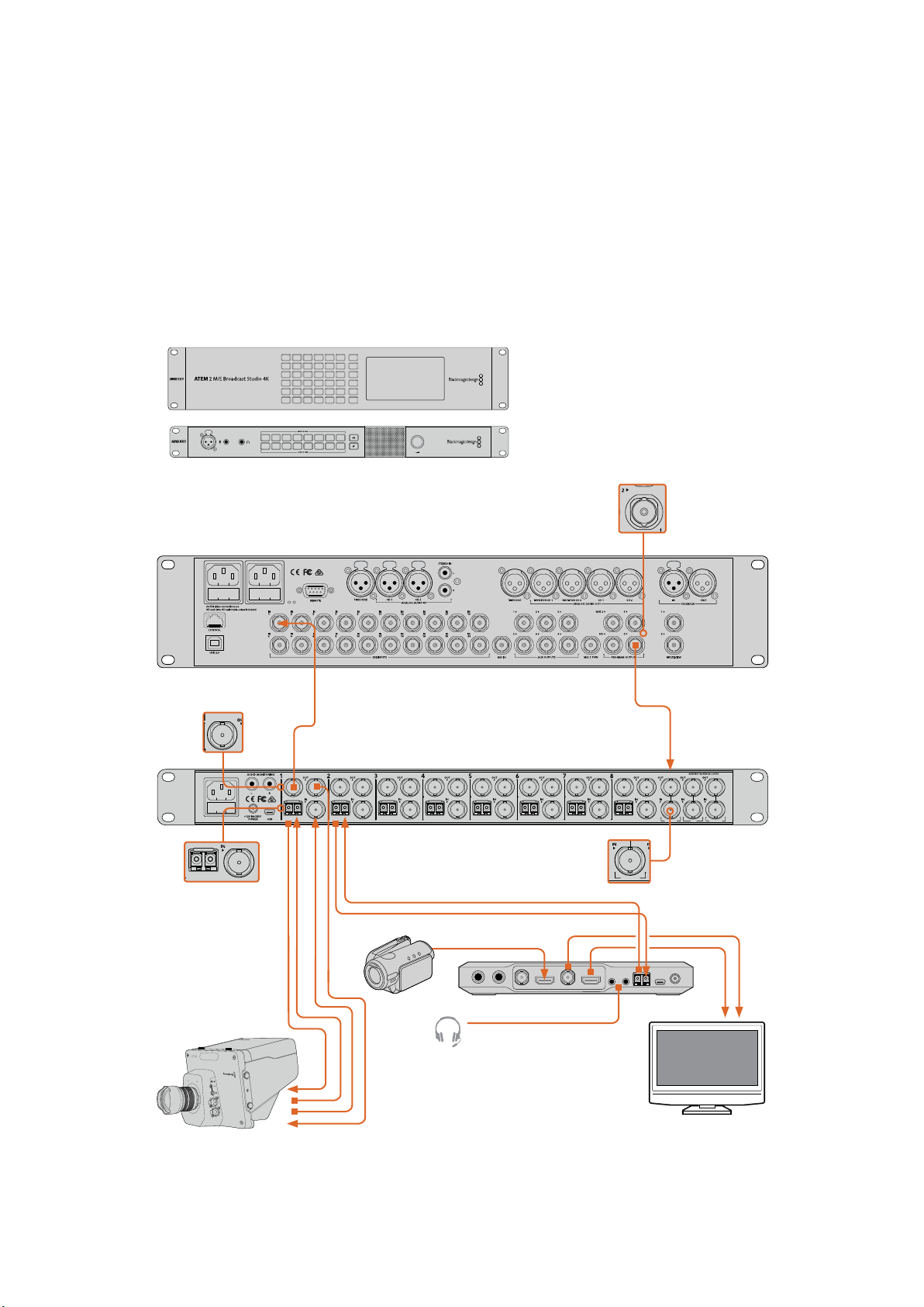
Connecting to an ATEM Switcher via ATEM Talkback Converter 4K
Using an ATEM Talkback Converter 4K with an ATEM switcher gives you talkback control with
tally for up to 8 cameras simultaneously. The example below shows an HD workflow using an
HDMI camera connected via optical fiber using an ATEM Camera Converter, plus a Blackmagic
Studio Camera via optical fiber or BNC.
PUSH
ATEM Talkback Converter 4K
SDI 1 out to ATEM switcher
camera 1 SDI in.
ATEM Talkback Converter
4K BNC or optic al fiber SDI
out/in to Blackmagic Studio
Camer a SDI out/in via BNC
or optical fiber.
1 2 3 4 5 6 7 8
1 2 3 4 5 6 7 8
SDI 1 OUT CAM SDI
CAM OPT
OUT/IN
ATEM 2 M/E Broadcast Studio 4K
SDI 2 OUT CAM SDI
CAM OPT
SDI 2 OUT CAM SDI
CAM OPT
OUT/IN
OUT/IN
ATEM Talkback Converter 4K
SDI 4 OUT CAM SDI
SDI 5 OUT CAM SDI
CAM OPT
CAM OPT
OUT/IN
OUT/IN
Optical Fiber In and Out
HDMI
SDI 6 OUT CAM SDI
CAM OPT
OUT/IN
SDI 7 OUT CAM SDI
CAM OPT
OUT/IN
SDI 8 OUT CAM SDI
CAM OPT
OUT/IN
ATEM switcher
program output.
PUSHPUSHPUSHPUSH
PGM SDI MIC H/PHONE
ATEM Talkback
Converter 4K PGM
SDI in from ATEM
switcher program
output.
1
1
3
2
PUSH
2
1
3
2
PUSH
Camera 1
Camera 2
ATEM Camera Converter
Headset via 3.5mm TRS input s
SDI or HDMI Mo nitor
21Connection Diagrams
Page 22
Connecting to an ATEM Switcher via
1 7 13 19 COL 1 BARS AUX 1
2 8 14 20 COL 2
SPR
SRC
AUX 2
3 9 15
KEY
MASK
CLEAN
FEED 1
ME 2
PVW
AUX 3
4 10 16 BLK
CLEAN
FEED 2
ME 2
PGM
AUX 4
5 11 17 MP 1 MP 1K
ME 1
PVW
AUX 5
6 12 18 MP 2 MP 2K
ME 1
PGM
AUX 6
1 7 13 19 COL 1 BARS AUX 1
2 8 14 20 COL 2
SPR
SRC
AUX 2
3 9 15
KEY
MASK
CLEAN
FEED 1
ME 2
PVW
AUX 3
4 10 16 BLK
CLEAN
FEED 2
ME 2
PGM
AUX 4
5 11 17 MP 1 MP 1K
ME 1
PVW
AUX 5
6 12 18 MP 2 MP 2K
ME 1
PGM
AUX 6
PTTPGM
VIDEOOPTICAL
PTTPGM
VIDEOOPTICAL
4321
OPTICAL OUT/IN
SDI OUT
L R
OPTICAL OUT/IN
SDI OUT
L R
ANALOG AUDIO OUT OPTICAL OUT/IN
SDI OUT
L R
ANALOG AUDIO OUT OPTICAL OUT/IN
SDI OUT
L
OUT
R
ANALOG AUDIO OUTANALOG AUDIO OUT
IN
PGM SDI
OUT
IN
MIC
OUT
IN
H/PHONE
AES/EBU TALKBACK LOOPS
PUSHPUSHPUSHPUSH
PUSHPUSHPUSHPUSH
1 7 13 19 COL 1 BARS AUX 1
2 8 14 20 COL 2
SPR
SRC
AUX 2
3 9 15
KEY
MASK
CLEAN
FEED 1
ME 2
PVW
AUX 3
4 10 16 BLK
CLEAN
FEED 2
ME 2
PGM
AUX 4
5 11 17 MP 1 MP 1K
ME 1
PVW
AUX 5
6 12 18 MP 2 MP 2K
ME 1
PGM
AUX 6
4321
SDI OUT
SDI OUT
SDI OUT
OUT
IN
OUTINOUT
IN
AES/EBU TALKBACK LOOPS
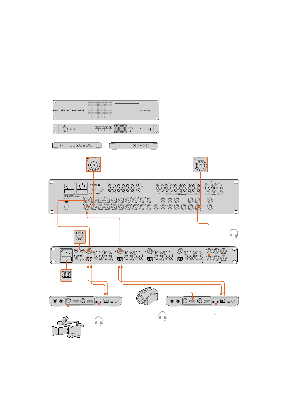
ATEMCamera and Studio Converters
This example shows a 3G-SDI workflow using two cameras connected to an ATEM 2 M/E
Broadcast Studio 4K via two ATEM Camera Converters partnered with an ATEM Studio
Converter. You can use ATEM Studio Converter’s XLR analog outputs to send each camera’s
audio to a mixing desk. ATEM Camera Converters can be used to convert HDMI cameras to SDI
so you can connect them to a switcher over long distances and get tally and talkback via
optical fiber.
PUSH
VIDEOOPTICAL
PRESS TO TALK
LOCK TO TALK
PTTPGM
SDI Camera 2 input
SDI camera output
to switcher
SDI out from ATEM
Studio Converter
to switcher
RL
SDI OUT
+12V BACKUP
POWER
USB 2.0
Optical fiber Out/In
SDI
OPTICAL OUT/IN
L R
ATEM Camera Converter
VIDEOOPTICAL
ATEM 2 M/E Broadcast Studio 4K
SDI OUT
L R
OPTICAL OUT/IN
ANALOG AUDIO OUT OPTICAL OUT/IN
ATEM Studio Converter
HDMI camera
PTTPGM
SDI OUT
L R
ANALOG AUDIO OUT OPTICAL OUT/IN
Optical Fiber In and Out
4321
SDI OUT
L
ANALOG AUDIO OUTANALOG AUDIO OUT
HDMI
ATEM Camera Converter
PUSHPUSHPUSHPUSH
OUT
IN
R
PGM SDI
Program output from
switcher to ATEM
Studio Converter
Headset connected to
inputs on front control
panel
AES/EBU TALKBACK LOOPS
OUT
OUT
IN
IN
MIC
H/PHONE
HD-SDI camera
Headset
Headset
22Connection Diagrams
Page 23
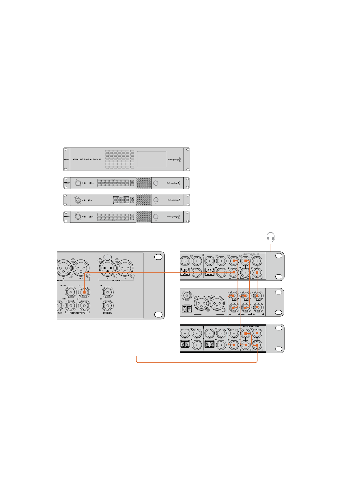
Looping Multiple ATEM Converters
1 7 13 19 COL 1 BARS AUX 1
2 8 14 20 COL 2
SPR
SRC
AUX 2
3 9 15
KEY
MASK
CLEAN
FEED 1
ME 2
PVW
AUX 3
4 10 16 BLK
CLEAN
FEED 2
ME 2
PGM
AUX 4
5 11 17 MP 1 MP 1K
ME 1
PVW
AUX 5
6 12 18 MP 2 MP 2K
ME 1
PGM
AUX 6
If you have more cameras than a single ATEM Talkback Converter 4K or ATEM Studio Converter
can support, you can expand the number of camera connections by linking ATEM Converters
together. This example shows two ATEM Talkback Converter 4K’s and an ATEM Studio
Converter connected together so up to 20 cameras can be used. The first unit receives the
program output from the switcher. The talkback headset or external microphone should be
connected to the front panel of the first unit. Thefirst unit’s program and microphone outputs
are then looped to the corresponding inputs of the next unit. The last unit in the chain should
loop its microphone output back to its own headphone input. The headphone output should be
connected to the headphone input of each previous unit in turn until the first unit is connected.
This completes the loop so that all ATEM Converters can share talkback.
PUSH
PUSH
PUSH
1 2 3 4 5 6 7 8
1 2 3 4 5 6 7 8
1 2 3 4 5 6 7 8
1 2 3 4 5 6 7 8
ATEM 2 M/E Broadcast Studio 4K
PRESS TO TALK
LOCK TO TALK
PUSH
The las t unit in the chain should
loop its microphone output back
to the headphone input on the
same unit.
SDI 7 OUT CAM SDI
CAM OPT
OUT/IN
SDI 8 OUT CAM SDI
CAM OPT
OUT/IN
ATEM Talkback Converter 4K
SDI OUT
L
OPTICAL OUT/IN
ANALOG AUDIO OUT
R
ATEM Studio Converter
SDI 7 OUT CAM SDI
CAM OPT
OUT/IN
SDI 8 OUT CAM SDI
CAM OPT
OUT/IN
ATEM Talkback Converter 4K
PGM SDI MIC H/PHONE
OUT
AES/EBU TALKBACK LOOPS
OUT
IN
IN
PGM SDI
MIC
PGM SDI MIC H/PHONE
OUT
IN
H/PHONE
23Connection Diagrams
Page 24

Help
Getting Help
The fastest way to obtain help is to go to the Blackmagic Design online support pages and
check the latest support material available for your ATEM converter.
Blackmagic Design Online Support Pages
The latest manual, software and support notes can be found at the Blackmagic Design Support
Center at www.blackmagicdesign.com/support.
Contacting Blackmagic Design Support
If you can’t find the help you need in our support material, please use the “Send us an email”
button, on the support page for your ATEM converter model, to email a support request.
Alternatively, click on the “Find your local support team” button on the support page and call
your nearest Blackmagic Design support office.
Using the Blackmagic Design Forum
The Blackmagic Design online forum on our website is another resource you can visit for
help. This can be a faster way of getting help as there may already be answers you can
find on the forum which will keep you moving forward. You can visit the forum at
https://forum.blackmagicdesign.com
Checking the Version Currently Installed
To check which version of Blackmagic Converters Setup software is installed on your computer,
open the About Blackmagic Converters Setup window.
On Mac OS X, open Blackmagic Converters Setup from the Applications folder.
Select About Blackmagic Converters Setup from the application menu to reveal the
version number.
On Windows 7, open Blackmagic Converters Setup from your Start menu.
Click on the Help menu and select About Blackmagic Converters Setup to reveal
the version number.
On Windows 8, open Blackmagic Converters Setup from the Blackmagic Converters
Setup tile on your Start page. Click on the Help menu and select About Blackmagic
Converters Setup to reveal the version number.
On Windows 10, open Blackmagic Converters Setup from your Start menu or click the
Blackmagic Converters Setup tile on your Start page. Click the Help menu and Select
About Blackmagic Converters Setup to reveal the version number.
How to Get the Latest Software Updates
After checking the version of Blackmagic Converters Setup software installed on your
computer, please visit the Blackmagic Support Center at www.blackmagicdesign.com/support
to check for the latest updates. While it is usually a good idea to run the latest updates, it is a
wise practice to avoid updating any software if you are in the middle of an important project.
24Help
Page 25

Regulatory Notices
Disposal of waste of electrical and electronic equipment within the European union.
The symbol on the product indicates that this equipment must not be disposed of with
other waste materials. In order to dispose of your waste equipment, it must be handed
over to a designated collection point for recycling. The separate collection and
recycling of your waste equipment at the time of disposal will help conserve natural
resources and ensure that it is recycled in a manner that protects human health and the
environment. Formore information about where you can drop off your waste
equipment for recycling, please contact your local city recycling office or the dealer
from whom you purchased the product.
This equipment has been tested and found to comply with the limits for a Class A digital
device, pursuant to Part 15 of the FCC rules. These limits are designed to
providereasonable protection against harmful interference when the equipment is
operated in a commercial environment. This equipment generates, uses, and can
radiate radio frequency energy and, if not installed and used in accordance with the
instructions, maycause harmful interference to radio communications. Operation of this
product in a residential area is likely to cause harmful interference, in which case the
user will be required to correct the interference at personal expense.
Operation is subject to the following two conditions:
1 This device may not cause harmful interference.
2 This device must accept any interference received, including interference that may
cause undesired operation.
Connection to HDMI interfaces must be made with high quality shielded HDMI cables.
This equipment has been tested for compliance with the intended use in a commercial
environment. If the equipment is used in a domestic environment, it may cause radio
interference.
25Regulatory Notices
Page 26
Safety Information
The following safety information applies to mains powered products.
This equipment must be connected to a mains socket outlet with a protective
earthconnection.
To reduce the risk of electric shock, do not expose this equipment to dripping
orsplashing.
This equipment is suitable for use in tropical locations with an ambient temperature of
up to 40ºC.
Ensure that adequate ventilation is provided around the product and is not restricted.
When rack mounting, ensure the ventilation is not restricted by adjacent equipment.
No operator serviceable parts inside. Refer servicing to your local Blackmagic Design
service centre.
Use only at altitudes not more than 2000m above sea level.
Some products have the facility to connect small form-factor transceiver (SFP) optical
fibre modules. Only use Laser class 1 optical SFP modules.
Recommended Blackmagic Design SFP modules:
3G-SDI: PL-4F20-311C
6G-SDI: PL-8F10-311C
12G-SDI: PL-TG10-311C
Warning for Authorized Service Personnel
Caution - Double Pole/Neutral Fusing
The power supply contained in this equipment has a fuse in both line and
neutral conductors and is suitable for connection to the IT power distribution
system in Norway.
26Safety Information
Page 27

Warranty
12 Month Limited Warranty
Blackmagic Design warrants that this product will be free from defects in materials and
workmanship for a period of 12 months from the date of purchase. If a product proves to be
defective during this warranty period, Blackmagic Design, at its option, either will repair the
defective product without charge for parts and labor, or will provide a replacement in exchange
for the defective product.
In order to obtain service under this warranty, you the Customer, must notify Blackmagic Design
of the defect before the expiration of the warranty period and make suitable arrangements for
the performance of service. The Customer shall be responsible for packaging and shipping the
defective product to a designated service center nominated by Blackmagic Design, with
shipping charges pre paid. Customer shall be responsible for paying all shipping charges,
insurance, duties, taxes, and any other charges for products returned to us for any reason.
This warranty shall not apply to any defect, failure or damage caused by improper use or
improper or inadequate maintenance and care. Blackmagic Design shall not be obligated to
furnish service under this warranty: a) to repair damage resulting from attempts by personnel
other than Blackmagic Design representatives to install, repair or service the product, b) to
repair damage resulting from improper use or connection to incompatible equipment, c) to
repair any damage or malfunction caused by the use of non Blackmagic Design parts or
supplies, or d) to service a product that has been modified or integrated with other products
when the effect of such a modification or integration increases the time or difficulty of servicing
the product.
THIS WARRANTY IS GIVEN BY BLACKMAGIC DESIGN IN LIEU OF ANY OTHER WARRANTIES,
EXPRESS OR IMPLIED. BLACKMAGIC DESIGN AND ITS VENDORS DISCLAIM ANY IMPLIED
WARRANTIES OF MERCHANTABILITY OR FITNESS FOR A PARTICULAR PURPOSE.
BLACKMAGIC DESIGN’S RESPONSIBILITY TO REPAIR OR REPLACE DEFECTIVE PRODUCTS IS
THE WHOLE AND EXCLUSIVE REMEDY PROVIDED TO THE CUSTOMER FOR ANY INDIRECT,
SPECIAL, INCIDENTAL OR CONSEQUENTIAL DAMAGES IRRESPECTIVE OF WHETHER
BLACKMAGIC DESIGN OR THE VENDOR HAS ADVANCE NOTICE OF THE POSSIBILITY OF
SUCH DAMAGES. BLACKMAGIC DESIGN IS NOT LIABLE FOR ANY ILLEGAL USE OF
EQUIPMENT BY CUSTOMER. BLACKMAGIC IS NOT LIABLE FOR ANY DAMAGES RESULTING
FROM USE OF THIS PRODUCT. USER OPERATES THIS PRODUCT AT OWN RISK.
© Copyright 2018 Blackmagic Design. All rights reserved. ‘Blackmagic Design’, ‘DeckLink’, ‘HDLink’, ‘Workgroup Videohub’,
‘Multibridge Pro’, ‘Multibridge Extreme’, ‘Intensity’ and ‘Leading the creative video revolution’ are registered trademarks in the
US and other countries. All other company and product names may be trade marks of their respective companies with which
they are associated.
27Warranty
Page 28

インストール/オペレーションマニュアル
ATEM
コンバーター
2018年11月
日本語
Page 29

ようこそ
こ の た び は 、ラ イ ブ プ ロ ダ ク シ ョ ン 用 に
ありがとうございます。
Blackmagic Design
コンバーターをお買い求めいただき誠に
ATEM Camera ConverterおよびATEM Studio Converterは 、放 送 用 SDIおよび民 生用HDMIカメ
ラを低価格の光ファイバーを用いて遠く離れた場所から使用できるようにします。レースサーキット
やライブスポーツ会場、広大なゴルフコースにカメラを設置できると想像してみてください!
Camera Converter
の で 、優 れ た シ ョ ッ ト が 撮 影 で き ま す 。
変換するだけでなく、トークバック、外部マイク入力、プログラムリターンフィード、タリー、内蔵バッ
テリー電源も搭載しています。スイッチャーから数キロ離れた場所にカメラを設置して、放送品質の
を使 用すれば 、ライブ プ ロダクションでカメラをアクションの 間 近に 配 置できる
ATEM Camera Converter
はカメラ の 信 号 を 光 ファイバ ー に
ATEM
HDビデオが 得 られます。
ATEM Studio Converterは、ATEM Camera Converterから分配されたプログラム出力とトークバ
ックに対 応 するためのsの完璧なパートナーです。複数の
と、4台を超 える 数のカメラでトークバックが 使 用できます。
多くのカメラを接続できます。また、長距離での使用が必要な場合は、オプションで光ファイバー
を取り付けて使用でき、
ャーとBlackmagic Studio CameraにATEMコンバーターを組み合わせて使用すれば、互いに機能
するように設計されたプロ仕様のビデオ機器でライブプロダクションを行えます。
Blackmagic Converters Setupは、ATEM
ートに使用します。最新バージョンの
ートページ
時間は約5分です。
新のマニュアルと
は 、弊 社 の
後に、ソフトウェアアップデートのダウンロード時にATEM Camera ConverterまたはATE M Studio
www.blackmagicdesign.com/jp
Twitter
12G-SDIで2160p60
までの
コンバーターの内部で設定変更やソフトウェアのアップデ
Blackmagic Converters Setup
でいつでもダウンロードできます。インストールの所 要
Blackmagic Converters Setup
Blackmagic Converters Setup
をフォローすることで、新しいソフトウェアアップデート情報が随時得られます。最
ATEM Studio Converter
ATEM Talkback Converter 4K
をル ープ 接 続 する
は 、さ ら に
SFP
Ultra HD
をインストールする前に、同サポートページで最
ソフトウェアをダウンロードしてください。あるい
ビデ オに 対 応してい ま す。
は 、弊 社 の ウ ェ ブ サ イ ト の サ ポ
ATEM
スイッチ
Converterを 登 録してください 。
ATEM
コンバー ターの 新しいソフトウェアアップデ ートや新 機能 を常 にお届けしたいと思 います。コン
バーターのご希望の改善点などもあれば、ぜひお聞きしたいと思います。常に新機能の開発および製
品の改善に努めていますので、ユーザーの皆様からご意見をいただければ幸いです。
Blackmagic Design CEO
グ ラ ン ト・ペ テ ィ
Page 30

目次
ATEM
はじめに 31
コンバーター について 31
ATEM
CameraConverterの接続 32
ATEM
StudioConverterの接続 34
ATEM
TalkbackConverter4Kの接続 37
ATEM
コンバーターのセットアップの確認 38
ATEM
CameraConverterの使用 40
ATE M
フロントパ ネ ルコントロール 40
ステータスインジケーター 40
コントロールパネルボタン 41
カメラ番号の設定 42
CameraConverterをマウントす る 42
ATEM
StudioConverterの使用 43
ATE M
フロントパ ネ ルコントロール 43
TalkbackConverter4Kの使用 44
ATE M
フロントパ ネ ルコントロール 44
Blackmagic
Blackmagic
Blackmagic
コンバーター のソフトウェアのアップデ ート 46
ATEM
タリーボーダーおよびカメラ番号の設定 46
接続図 47
TalkbackConverter4Kを介してATEMスイッチャーを接続 47
ATEM
CameraConverterおよびStudioConverterを介して ATEMスイッチャーを接続 48
ATEM
複数のATEMコンバ ー タ ー を ル ープ 接 続 す る 49
ヘルプ 50
規制に関する警告 51
安全情報 52
保証 53
コンバーター
ConvertersSetupの使用 45
ConvertersSetupのインストール 45
ConvertersSetupの削除 46
Page 31

はじめに
ATEM
ATEM Camera Converter、ATEM Studio Converter、ATEM Talkback Converter 4Kは、ATEMスイッ
チャーなどのスイッチャーに接続することで、スタジオトークバックおよびタリーを使用できます。さらに、
オプションで低価格の光ファイバーケーブルを取り付ければ、長距離の接続も可能です。
コンバーターについて
ATEMCameraConverter
ATEM Camera Converter
Camera Converter
Converterなどのリモートユニットに送信します。その後、信号はそれらの機器からスイッチャーに送られます。
ATEM Camera Converterは、SD、HD、3G-SDIフォーマットに対応しており、電源は充電可能な内部バ
ッテリーまたは主電源を使用できます。
他の
ATEM Camera ConverterやATEM Studio Converter、ATEM Talkback Converter 4Kと共に使用
することで、ライブプロ ダクションの 完 全 なトー クバックソリューションが 得られます。
と接続すると、タリーライトも有効になります。
は 、あ ら ゆ る
は、双方向光ファイバーでビデオ、オーディオ、タリー、トークバック信号を
SDI/HDMI
カメラを接続できるポータブルなコンバーターです。
ATEM
ATEM
ATEM Studio
スイッチャ ー
ATEMCameraConverter
ATEMStudioConverter
ATEM Studio Converterを 光ファイバ ー で ATEM Camera Converterに 接 続 す る と 、あ ら ゆ る SDI/HDMIカ
メラでトークバックが使用できるようになります。ビデオを長距離のケーブルで送信する必要がある場合、
最大4台まで の カメラを 光 ファイバ ー SDIに変 換できます。
LC
コネクタ ー 付 きのシングル モ ードの 光ファイバーで 、
に接 続 できます。
で き ま す 。光 フ ァ イ バ ー 入 力 お よ び SDI接続は、SD、HD、 6G-SDIビ デ オに対 応 しています。
カメラのオーディオ出力を外部ミキサーに接続するのは簡単です。
のバランス
4台を超える数のカメラが必要な場合、複数のATEM Studio ConverterとATEM Talkback Converter 4K
をル ープ 接 続 で き ま す。
Blackmagic Studio Camera
XLRアナログ出力に接 続するだけです。
ATEM Camera ConverterをATEM Studio Converter
を使用している場合、ビデオ入力を光ファイバーで直接接続
ATEM Studio Converterのリアパネル
ATEMStudioConverter
はじめに
31
Page 32

ATEMTalkbackConverter4K
PTTPGM
VIDEOOPTICAL
PTTPGM
VIDEOOPTICAL
ATEM Talkback Converter 4K
ます。
ATEM
スイッチャー に 接 続 するとタリーが 使用できるようになり、また 光ファイバーで
Converterに接 続 するとトー クバックも追 加 できます。
は 、最 大8台のカメラに同軸ケーブルで接続でき、
12G-SDI
まで 対 応 してい
ATEM Camera
Blackmagic Studio Cameraは、BNC
または オプションの 光ファイバー モジュー ル を 介 して
ATEM Talkback
Converter 4Kに 接 続 できます。 ATEMスイッチャー に 接 続 すると、トークバックとタリー も使用できます。
さらに多くのカメラを接続する必要がある場合、
せることも 可 能で す。
対 応しています。
ATEMTalkbackConverter4Kは 、オ プ シ ョ ン の 光 フ ァ イ バ ー SFPモジュー ルを8個まで挿入可能。
ATEM Talkback Converter 4Kは、2160p60
ATEM Camera Converter
まずATEM Camera Converterの 電 源を入れ 、次にカメラ、ヘッドセット、モニターを接 続します。
ATEM Talkback Converter 4Kを追加してループ接続さ
までのSD、HD、
Ultra HD
の接続
ビデオに
電源の接続
ATEM Camera Converter
電源アダプターに接続できるコネクターも搭載しています。
は
12V〜31V
は、電源に接続されると充電されます。
の電源入力をサポートしているため、外部カメラバッテリーも使用できます。内部バッテリー
は、充電可能な内部バッテリーを搭載しているためロケ先で使用でき、同梱の
ATEM Camera Converter
の電 源 コネクター
電源に接続し、12V〜31V電源コネクター経由で内部バッテリーを充電します。SDI/HDMI
入力経 由 でカメラを、SDI/HDMI出力経由で モニターを接 続しますデフォルトで は 、ATEM
CameraConverterはカメラからのエンベデッドSDI/HDMIオー ディオを使用します。
カメラの 接 続
カメラを ATEM Camera ConverterのHDMIまたは SDIコネクタ ー に接 続 します。
カメラの出 力 は 、必 ずライブ プ ロダクションスイッチャ ー が 対 応 しているフォーマットに設 定してくださ
い。
ATEM
スイッチャーに接 続 する場 合 、スイッチャーのビ デ オフォーマットを確 認し、カメラを同じフォー
マ ッ ト( 例 : 1080i59.94)に 設 定 し ま す 。
はじめに
32
Page 33

ヘッド セット の 接 続
PTTPGM
VIDEOOPTICAL
PTTPGM
PTTPGM
VIDEOOPTICAL
PTTPGM
トー クバ ックヘッド セットを
ドフォン 入 力 に 接 続 します。
でのみ接続できます。しかし、同時に外部マイクを接続している場合は、外部マイクのみが使用されます。
ヘッド セットを 標 準 3.5mmヘッドフ ォン 出 力 お よ び マイク 入 力 で ATEMCameraConverterに接続。
ATEM Camera Converter
iPhone
または
Android
と互 換 性の あ る ヘッド セットは 、ヘッドフ ォン ジ ャック
の標準3.
5mm
ステレオアナログマイクおよびヘッ
モニターの接続
モニター を
力ま た は スイッチャ ー の プ ロ グ ラム 出 力 を 確 認で きま す。
Camera Converter
替わった際にタリーライトが点 灯します。詳 細は「
の設定」を参照してください。
ATEM Camera ConverterのSDI/HDMI
でカメラ番号を設定する必要があります。これにより、カメラがプログラム出力に切り
出力に接 続します。モニターを使用することで、カメラ出
ATEM
スイッチャーに接続している場合、
ATEM Camera Converter
の使用」および「カメラ番号
ATEM
光ファイバ ーで 接 続
ATEM Camera Converterを2台目のATEM Camera ConverterやATEM Talkback Converter 4Kまたは
ATEM Studio Converter
を使 用します。一 対 になった 光 ファイバーケ ーブル は 、パッチコードとも呼 ば れます。
ATEMCameraConverterの光 ファイバ ー SFPモジュール 。
に接 続するには、LCコネクター 付 きデュプレックス・シングル モ ード 光ファイバー
光ファイバ ー のLCコネクターの接続
ATEMコンバーターに光ファイバーコネクターを接続する:
1 パッチコ ードの 片 方の 端 を ATEM Camera ConverterのSFPモジュールに 接 続します。
2
パッチコ ードのもう一 方 の端 を2台目の
複 数 のカメラを ATEM Talkback Converter 4KまたはATEM Studio Converterに 接 続 してい る 場
合、各カメラに適切な
SFPモジュー ルを選 択します。
ATEM Camera ConverterのSFP
モジュールに 接 続します。
はじめに
33
Page 34

例 え ば 、カ メ ラ 1に接続する場合は、カメラ1のSFPモジュー ル に 接 続します。
PTTPGM
VIDEOOPTICAL
PTTPGM
VIDEOOPTICAL
PTTPGM
VIDEOOPTICAL
VIDEOOPTICAL
LCコネクタ ー 付 き の 光 ファイバ ー パッチコ ー ド 。
オーディオの接 続
ATEM Camera Converterは、2
イバー SDI接 続 の オー ディオ チ ャン ネ ル 1と2で 送 信 さ れ ま す 。デ フ ォ ル ト で は 、 ATEM Camera Converter
はカメラのマイクからのエンベデッドオーディオを使用します。しかし、外部オーディオソースを接 続したい
場合は、
部オーディオが接続されている場合、エンベデッドオーディオの代わりに外部オーディオが使用されます。
1/4
の オ ー ディオ チャンネル 1と2で 送 信します。
ATEM Camera Converterの2
インチ
TRS
コネクター は、マイクレベルのステレオアナログオーディオを受信でき、光ファイバー
チャンネルのカメラオーディオをサポートしており、これらの信 号は 光ファ
つの バランス1/4インチ
TRS
入力にオーディオ機器を接続します。外
SDI
接続
外部オーディオ機器をTRSコネクターで接続。
ビデオ信号の確認
ATEM Camera Converterへの給電が行われ、カメラが接続されており、有効なSDI/HDMI信号がある場
合 、コ ン ト ロ ー ル パ ネ ル の「 VIDEO」ステ ータスインジ ケ ー タ ー が 点 灯します。
さ ら に 、モ ニ タ ー を 接 続 し て お り 、
れるため、ATEM Camera Converterが機能していることが確認できます。
有効なビデオ信号がSDIまたはHDMI経由で検出されると、ATEMCameraConverterの「 VIDEO」ステータスインジケータ
ー が 点 灯 し ま す 。「
OPTICAL」インジケーターは、光ファイバー入力経由で有効なSDI信号が検出されると点灯します。
ATEM Studio Converter
まず電源を入れ、次にカメラ、ヘッドセット、スイッチャーを接続します。また、外部マイクも接続できます。
ヘッドセットを使わず にトー クバックを使 用したい 場 合 、グースネックマイクなどを 接 続します。さらに 、各 カ
メラのオーディオをバランスアナログ XLRでミキサ ー に出力することもできます。
PGM
ボタンをカメラのビデオに設定している場合、カメラ出力が表示さ
の接続
はじめに
34
Page 35

電源の接続
4321
OPTICAL OUT/IN
SDI OUT
L R
RL
USB 2.0
+12V BACKUP
POWER
OPTICAL OUT/IN
SDI OUT
L R
ANALOG AUDIO OUT OPTICAL OUT/IN
SDI OUT
L R
ANALOG AUDIO OUT OPTICAL OUT/IN
SDI OUT
L
OUT
R
ANALOG AUDIO OUTANALOG AUDIO OUT
IN
PGM SDI
OUT
IN
MIC
OUT
IN
H/PHONE
AES/EBU TALKBACK LOOPS
PUSH
LOCK TO TALK
PRESS TO TALK
4321
OPTICAL OUT/IN
SDI OUT
L R
RL
USB 2.0
+12V BACKUP
POWER
OPTICAL OUT/IN
SDI OUT
L R
ANALOG AUDIO OUT OPTICAL OUT/IN
SDI OUT
L R
ANALOG AUDIO OUT OPTICAL OUT/IN
SDI OUT
L
PUSH
LOCK TO TALK
PRESS TO TALK
4321
OPTICAL OUT/IN
SDI OUT
L R
RL
USB 2.0
+12V BACKUP
POWER
OPTICAL OUT/IN
SDI OUT
L R
ANALOG AUDIO OUT OPTICAL OUT/IN
SDI OUT
L R
ANALOG AUDIO OUT OPTICAL OUT/IN
SDI OUT
L
OUT
R
ANALOG AUDIO OUTANALOG AUDIO OUT
IN
PGM SDI
OUT
IN
MIC
OUT
IN
H/PHONE
AES/EBU TALKBACK LOOPS
PUSH
LOCK TO TALK
PRESS TO TALK
OPTICAL OUT/IN
SDI OUT
L R
OPTICAL OUT/IN
SDI OUT
L R
ANALOG AUDIO OUT OPTICAL OUT/IN
SDI OUT
LOCK TO TALK
PRESS TO TALK
標準
IEC
ケ ーブ ルを 使 用して 、
ーや 外 部 カメラバッテリー を 12V〜31Vの電源入力に接続することも可能です。
2
つの電源入力によるリダンダント電源に対応しているため、電源に何らかの問題が生じた場合や、誤って
接続が外れた場合にも電源が得られます。
主電源、あるいは12Vまたは31V電源コネクターに接続。
ATEM
コンバーターの主電源入力に電源を接続します。また、電源アダプタ
カメラの 接 続
ATEM Studio Converterのリアパ ネル には 、 1から 4に番号が振られた 4グループのコネクターが搭載され
ています。
1 カメラをそれ ぞ れ の 光 ファイバ ー SFPモジュー ル に 接 続します。
2
SFP
モジュールに接続した2つ目のLCコ ネ ク タ ー は 、プ ロ グ ラ ム ビ デ オ を
Blackmagic Studio Camera
またはATEM Camera Converterに送り戻すために使用されます。
3
ATEM Studio Converter
カメラをATEMStudioConverterの光ファイバー入力に接続。
からの 各 カメラ
SDI
出力をスイッチャーの対応するカメラ入力に接 続します。
スイッチャーからのプログラムフィードの接続
スイッチャ ー から のプ ロ グ ラム 出 力 を
スイッチャーからのプログラム出力を接続している場合、タリーもSDI信 号 に エ ン ベ ッ ド さ れ ま す 。こ れ に よ
り、ATEM Camera Converterを光ファイバーを介してBlackmagic Studio Cameraに接続している場合
にタリーライトが使用可能になります。
ATEM Studio Converterの「PGM SDI
」入 力 に 接 続 し ま す 。
ATEM
はじめに
35
Page 36

4321
SDI OUT
L R
ANALOG AUDIO OUT OPTICAL OUT/IN
SDI OUT
L R
ANALOG AUDIO OUT OPTICAL OUT/IN
SDI OUT
L
OUT
R
ANALOG AUDIO OUTANALOG AUDIO OUT
IN
PGM SDI
OUT
IN
MIC
OUT
IN
H/PHONE
AES/EBU TALKBACK LOOPS
LOCK TO TALK
PRESS TO TALK
IN
PGM SDI
OUT
IN
MIC
OUT
IN
H/PHONE
AES/EBU TALKBACK LOOPS
スイッチャーからのSDIプロ グラム出力を ATEMStudioConverterの「 PGMSDI」入力に接続。
PUSH
LOCK TO TALK
PRESS TO TALK
4321
OPTICAL OUT/IN
SDI OUT
L R
RL
USB 2.0
+12V BACKUP
POWER
OPTICAL OUT/IN
SDI OUT
L R
ANALOG AUDIO OUT OPTICAL OUT/IN
SDI OUT
L R
ANALOG AUDIO OUT OPTICAL OUT/IN
SDI OUT
L
OUT
R
ANALOG AUDIO OUTANALOG AUDIO OUT
IN
PGM SDI
OUT
IN
MIC
OUT
IN
H/PHONE
AES/EBU TALKBACK LOOPS
PUSH
LOCK TO TALK
PRESS TO TALK
4321
RL
LOCK TO TALK
PRESS TO TALK
4321
L R
ANALOG AUDIO OUT OPTICAL OUT/IN
SDI OUT
L
OUT
R
ANALOG AUDIO OUTANALOG AUDIO OUT
IN
PGM SDI
OUT
IN
MIC
OUT
IN
H/PHONE
AES/EBU TALKBACK LOOPS
ヘッド セット の 接 続
ATEM Studio Converter
チマイクジャックに接続して使用できます。ヘッドセットと外部マイクの両方が接続されている場合、ヘッド
セットのみ が 使 用 されます。トー クバックオー ディオは 、
ッドさ れま す。
航空機用ヘッドセットをATEMStudioConverterのフロントパ ネ ルにある TRSコネクターに接続。
ま た 、外 部 マ イ ク を バ ラ ン ス
では、航空機用ヘッドセットを1/4インチ
SDI
XLRアナログ入力に接続することも可能。
TRS
ヘッドフォンジャックと0.
206
イン
信 号 の オ ー ディオチャンネル15と16にエンベ
外部マイクの接続
外部マイクを使用したい場合、
アナログ入力に接続します。
ATEM Studio Converter
のフロントコントロ ールパ ネ ル にあるバランス
XLR
カメラオー ディオの出力
カメラのオーディオ出力を外部ミキサーに接続するのは簡単で、リアパネルのバランス
に接 続 するだけ です。
XLR
アナログ出力
オー ディオ の モニタリング
プログラムまたはトークバックオーディオをBlackmagic Audio Monitorなどの外部オーディオ機器でモニ
タリングしたい場合、
オー ディオは
外部オーディオ機器をATEMStudioConverterのRCA出力に 接 続して、
プログラムまたはトー クバックオーディオをモニタリング。
XLRアナログ出力を使 用すれば、ミキサ ー に簡 単に接 続できます。
ATEM Studio Converterのリアパネル にある RCA出 力 に 接 続 し ま す 。ま た 、カ メ ラ の
はじめに
36
Page 37

ATEM Talkback Converter 4K
PGM SDI MIC H/PHONE
SDI 1 OUT CAM SDI
CAM OPT
OUT/IN
SDI 2 OUT CAM SDI
CAM OPT
OUT/IN
SDI 2 OUT CAM SDI
CAM OPT
OUT/IN
SDI 4 OUT CAM SDI
CAM OPT
OUT/IN
SDI 5 OUT CAM SDI
CAM OPT
OUT/IN
SDI 6 OUT CAM SDI
CAM OPT
OUT/IN
SDI 7 OUT CAM SDI
CAM OPT
OUT/IN
SDI 8 OUT CAM SDI
CAM OPT
OUT/IN
SDI 1 OUT CAM SDI
CAM OPT
OUT/IN
SDI 2 OUT CAM SDI
CAM OPT
OUT/IN
SDI 2 OUT CAM SDI
CAM OPT
OUT/IN
SDI 4 OUT CAM SDI
CAM OPT
OUT/IN
SDI 5 OUT CAM SDI
CAM OPT
OUT/IN
SDI 6 OUT CAM SDI
CAM OPT
OUT/IN
SDI 7 OUT CAM SDI
CAM OPT
OUT/IN
PGM SDI MIC H/PHONE
SDI 1 OUT CAM SDI
CAM OPT
OUT/IN
SDI 2 OUT CAM SDI
CAM OPT
OUT/IN
SDI 2 OUT CAM SDI
CAM OPT
OUT/IN
SDI 4 OUT CAM SDI
CAM OPT
OUT/IN
SDI 5 OUT CAM SDI
CAM OPT
OUT/IN
SDI 6 OUT CAM SDI
CAM OPT
OUT/IN
SDI 7 OUT CAM SDI
CAM OPT
OUT/IN
SDI 8 OUT CAM SDI
CAM OPT
OUT/IN
SDI 1 OUT CAM SDI
SDI 2 OUT CAM SDI
SDI 2 OUT CAM SDI
SDI 4 OUT CAM SDI
SDI 5 OUT CAM SDI
SDI 2 OUT CAM SDI
CAM OPT
OUT/IN
SDI 2 OUT CAM SDI
CAM OPT
OUT/IN
SDI 4 OUT CAM SDI
CAM OPT
OUT/IN
SDI 5 OUT CAM SDI
CAM OPT
OUT/IN
の接続
まず電源を入れ、次にカメラ、ヘッドセット、スイッチャーを接続します。また、外部マイクも接続できます。ヘ
ッドセットを使 わずにトークバックを 使 用したい 場 合 、グースネックマイクなどを接 続します。
電源の接続
標準
IEC
ケ ーブ ルを 使 用して 、
電 源 アダプターや外 部カメラバッテリーを
力によるリダンダント電源に対応しているため、電源に何らかの問題が生じた場合や、誤って接続が外れた
場合にも電源が得られます。
主電源、あるいは12Vまたは31V電源コネクターに接続。
ATEM Talkback Converter 4K
12V〜31V
の電源入力に接続することも可能です。2つの電源入
の主電源入力に電源を接続します。また、
カメラの 接 続
ATEM Talkback Converter 4Kの リ ア パ ネ ル に は 、カ メ ラ 番 号 1から8に割り当てられた 、 8グル ープ のコネ
クターが 搭 載 されています。
1 カ メ ラ を 各「 Cam SDI IN」コ ネ ク タ ー に 接 続 し ま す 。
2 ATEM Talkback Converter 4Kの「 Cam SDI OUT」を カ メ ラ の プ ロ グ ラ ム SDI入力 に 接 続します。
ATEM Camera ConverterをATEM Talkback Converter 4K
タリー は 光 ファイバ ー 経 由 で のみ SDI信 号 にエンベ ッドさ れ ることにご 注 意ください 。
と使用している場合、トークバックと
3 番 号がついたSDI出 力( 例 : SDI 1 OUT)をスイッチャーの対 応するカメラ入力に接続します。
カメラをATEMTalkbackConverter4Kの カメラSDI入力に接続。光ファイバーSFPモジュー ルが 取
り付けている場合、光ファイバー経由でカメラを
能。
ATEMTalkbackConverter4Kの「 SDIOUT」をスイッチャーに接続。
ATEMTalkbackConverter4Kに接 続 することも 可
はじめに
37
Page 38

スイッチャーからのプログラムフィードの接続
PGM SDI MIC H/PHONE
SDI 2 OUT CAM SDI
CAM OPT
OUT/IN
SDI 4 OUT CAM SDI
CAM OPT
OUT/IN
SDI 5 OUT CAM SDI
CAM OPT
OUT/IN
SDI 6 OUT CAM SDI
CAM OPT
OUT/IN
SDI 7 OUT CAM SDI
CAM OPT
OUT/IN
SDI 8 OUT CAM SDI
CAM OPT
OUT/IN
PGM SDI MIC H/PHONE
1 2 3 4 5 6 7 8
1 2 3 4 5 6 7 8
スイッチャ ー から のプ ロ グ ラム 出 力 を
ます。
ATEM
スイッチャーからのプログラム出力を接続している場合、タリーも
す 。こ れ に よ り 、
ATEM Camera Converter、Blackmagic Studio Camera、Blackmagic URSA Broadcast
に接続している場合にタリーライトが使用可能になります。
スイッチャーからのSDIプロ グラム出力を ATEM
TalkbackConverter4Kの「 PGMSDI」入力に接続。
ATEM Talkback Converter 4Kの「PGM SDI IN
SDI
信 号 にエ ン ベ ッドさ れ ま
」コ ネ ク タ ー に 接 続 し
ヘッド セット の 接 続
ATEM Talkback Converter 4Kでは、航空機用ヘッドセットを1/4インチ TRSヘッドフォンジャックと 0.206
インチマイクジャックに接 続 して使 用 で きます。
ヘッドセットと外部マイクの両方が接続されている場合、ヘッドセットのみが使用されます。
トー クバックオーディオは 、
航空機用ヘッドセットをATEMTalkbackConverter4Kのフロントパ ネルにある TRSコネクターに接続。また、
ヘッドセットを使わずトークバックを使用したい場 合 は 外 部マイクをバランス
SDI信 号 の オ ー ディオチャンネル 15と 16に エ ン ベッドさ れま す。
XLRアナログ入力に接続することも可能。
外部マイクの接続
外部マイクを使用したい場合、ATEMコンバーター のフロントコントロ ー ルパネルにある バランス XLRアナ
ログ 入 力 に 接 続します。
オー ディオ の モニタリング
プログラムまたはトークバックオーディオをBlackmagic Audio Monitorなどの外部オーディオ機器でモニ
タリングしたい場合、
RCA出力に接 続 します。
ATEM
コンバ ー タ ー の セットアップ の 確 認
ATEM Talkback Converter 4Kまたは ATEM Studio Converterのリアパネル にある
ATEMコンバーターをライブプロダクションスイッチャーに接続した後は、すべて正常に機能しているか確
認します。
まず、カメラからの有効な信号をスイッチャーが受信しているか確認します。これは、スイッチャーの担当
者が各カメラをプレビューまたはプログラム出力に切り替えることで確 認できます。すべてのカメラの 信号
がスイッチャーのプレビューまたはプログラム出力で確認できれば 、
ことを 意 味 します。
ATEM
コンバー タ ー が 機 能している
はじめに
38
Page 39

次は 、トークバックのチェックで す。スイッチャー の 担当 者とカメラマン が 、プレス・トゥ・トークボタンとヘッ
INPUT DISP
H/V
DELAY3DLUT 1
BLUE
ONLY
ZOOM PEAK
3D
LUT 2HMARKVMARK
1
1
3
PUSH
2
2
1
3
PUSH
2
1 4 7 10 COL 1 COL 2
CLEAN
FEED 1
BARS 1
2 5 8 MP 1
CLEAN
FEED 2
MP 1
KEY
PVW 2
3 6 9 BLK MP 2
KEY
MASK
MP 2
KEY
PGM 3
1 M/E Production Studio 4K
PUSH
1 2 3 4 5 6 7 8
1 2 3 4 5 6 7 8
ドセットを使用して、互いに通信できるか確認します。
ATEMスイッチャーを使用している場合、タリー信号はSDI接続を介して送信されます。タリーが機能してい
ることを 確 認 す る に は 、
していることをチェックします。詳 細 は、このマニュアル の「 ATEM Camera Converterの使用」または「カメ
ラ番号の設定」セクションを参照してください。
ATEM
コンバ ー タ ー の セットア ップ に 問 題が 生 じてい る 場 合 は 、
(
www.blackmagicdesign.com/jp/support
富なユーザーや
Blackmagic Design
ま た 、お 近 く の Blackmagic Designサポートチームの連絡先も確認できます。
ATEM Talkback Converter 4K
ATEM Camera Converter
)ま た は
のスタッフによる、問題解決に役立つ情報やコメントを確認できます。
ATEM 1 M/E Production Studio 4K
のカメラ番 号と
Blackmagic
ATEM
スイッチャーのカメラ番号が一致
Blackmagic Design
のサポートセンター
のフォーラムをご確認ください。経験豊
Blackmagic Studio
Camera
HDMIカメラ
VIDEOOPTICAL
PTTPGM
ATEM Camera Converter
モニター
ATEMコンバーターの接続方法の詳細は「接続図」セクションを参照してください。
はじめに
39
Page 40

ATEM Camera Converter
PTTPGM
VIDEOOPTICAL
PTTPGM
VIDEOOPTICAL
の使用
フロントパ ネルコントロール
ATEM Camera Converterのコントロールパネルは、ヘッドフォンおよびマイクの音量調整、トークバックの
有効化、プログラム/カメラモニタリング、電源のオン/オフ、カメラ番号の設定を行うためのボタンを搭載
しています。また、バッテリーレベル、光信号、
ーも 搭 載 して い ます。
SDI/HDMI
信号、タリー用の5つの ステータスインジケータ
ステータスインジケーター
バッテリーレベル
コントロールパネルの左端には、バッテリーレベルを示すインジケーターの4つ の 緑 の ラ イ ト が あ り ま す 。バ
ッテリーの残量が減るとインジケーターのライトが消えていきます。インジケーターの最後のライトが点滅
し 始 め る と 、バ ッ テ リ ー の 残 量 が 約 10分になったことを示します。この場合、外部電源に接続するか、十分に
充電された
約2時間使用でき、完全に充電するには約8時 間 か かります。
OPTICAL(光ファイバー)
バッテリーレベルの
ファイバ ー
号の送受信を確認します。
ATEM Camera Converter
LED
の 隣 に は「
SDI
ビデオ信号を検出すると、このライトが点灯します。このインジケーターで有効な
に切り替える必要があります。バッテリーは、継続的な使用において
OPTICAL
」イ ン ジ ケ ー タ ー が あ り ま す 。
ATEM Camera Converter
SDI
が光
入力信
VIDEO(ビデオ)
ATEM Camera Converterが有効なSDI/HDMIビ デ オ 信 号 を 検 出 す る と 、「 VIDEO」イ ン ジ ケ ー タ ー の ラ イ
トが点灯します。このインジケーターでカメラの入力信号があるか確認します。
タリー ラ イト
ATEM
スイッチャーのプログラム出力からタリー信号を受信すると、タリーライトが点灯します。
Camera Converter
とカメラマンはオン エア 中 かどうか確 認できます。
バッテリーレベ ル 、OPTICAL、VIDEOステータスインジケーター。
の各側面に1つずつ搭載された合計2つの赤いタリーライトを確認することで、出演者
VIDEOOPTICAL
PTTPGM
ATEM
ATEMCameraConverterの各サイドのタリーライトは、ATEMスイッチャ ー
のプログラム出力でカメラがライブになると赤で点 灯 。
ATEMCameraConverterの使用
40
Page 41

コントロ ールパネル ボタン
PTTPGM
VIDEOOPTICAL
PTTPGM
PTTPGM
VIDEOOPTICAL
PTTPGM
PTTPGM
PGM(プログラム )
PGM
ボ タ ン は 、プ ロ グ ラ ム ビ デ オ 信 号 と カ メ ラ 入 力 信 号 の 切 り 替 え に 使 用 し ま す 。プ ロ グ ラ ム 入 力 は 、光 フ
ァイバーを介して接続されている信号です。
PGMボタンおよび マイク音 量レベ ルボタン。これらの ボタンは 、
押すか、有効化すると点灯。
マイク ボリュー ム DOWN/UP
マイク音量ボタンでは、外部オーディオのレベルをすばやく調整できます。ボタンを押すたびに、1秒間かけて
スムーズに音量が上下します。最大/最低のマイクボリュームに達するか、起動時に最大/最低のボリュームの
場合、該当のボタンが3秒間点灯します。これらのボタンは、カメラから直接受信するエンベデッド
オーディオのレベルには影響しません。
SDI/HDMI
電源オン/オフ
ボタンを押してリリースすると、電源 が瞬時にオンになります。電 源をオフにするには、1秒 間 ボタンを押し
ます。
カメラ番 号
ATEM Camera Converterでカメラ番号を設定する際に使用することで、タリーライトが正確に機能します。
詳細は、このマニュアルの「カメラ番号の設定」セクションを参照してください。
トー クバックヘッドフォンのボリューム
このボタンを使用して、トークバックヘッドフォンのボリュームを上げます。最大のボリュームに達するか、
起動時に最大のボリュームの場合、ボタンが3秒間点灯します。次にボタンを押すと、最低のボリュームに
戻り、その後 、再び押すたびに上がっていきます。
PTT( プ レ ス・ト ゥ・ト ー ク )
カメラマンとスイッチャーが会話する必要がある場合に使用します。会話中はボタンを押したままにします。
PTT
ボタンをす ば やく2度押しすると、ハンズフリー通信が行えます。再度ボタンを押すと、通常のトークバ
ックに戻ります。
ATEMCameraConverterが起動されると電源ボタンが点灯。PTTボ タ ン を 押 す と 、他 の ATEM
CameraConverterやATEMTalkbackConverter4K、ATEMStudioConverterとトー クバ
ックが可能。トークバックヘッドフォンのボタンでトークバック音量を調整。
ATEMCameraConverterの使用
41
Page 42

カメラ番号の設定
PTTPGM
VIDEOOPTICAL
PTTPGM
ATEM
スイッチャーからのタリー 信 号を
Converter
でカメラ番号を設定する必要があります。これにより、スイッチャーから適切な
Converterにタリー信号を送信できます。カメラ番号は1〜99に設定可能です。
カメラ番号ボタンでカメラ番号を設定するには、ボタンのライトが3回点滅するまでボタンを長押しします。
これ により、カメラ 番 号 をカメラ1にリセットします。その 後 、ボタンを押 すたびにカメラ番 号 が1ずつ上 がりま
す 。例 え ば 、 ATEM Camera Converterをカメラ番 号 5に設定したい場合、まずカメラ番号を1にリセットし
て 、そ の 後 ボ タ ン を
カメラ 番 号 が 5に 設 定されたかどうか は 、 ATEMスイッチャーの担当者がプログラム出力をカメラ番号5に
切り替えることで確認できます。カメラ番号が正確に設定されていると、
リーライトが 点 灯します。
4回 押します。
ATEM Camera Converter
で受信したい場合、
ATEM Camera Converter
ATEM Camera
ATEM Camera
のタ
同様に、
担当 者がプログラム出力へのカメラ入力をタリーライトが点灯するまで切り替えます。これにより、スイッチ
ャーの担当者はATEM Camera Converterのカメラ番号を確認できます。
カメラ番 号 ボ タン。
ATEM Camera Converter
カメラを移動する必要がある場合、ケーブルをATEM Camera Converterに接続して、次にベルトクリップ
でベ ルトに取り付けて使 用できます。固 定ショットには、
たは1/4イ ン チ ス レ ッ ド で 三 脚 ア ー ム に マ ウ ン ト で き ま す 。ゴ ム 製 の 脚 で
に設置する場合は、2個の2.5mm六 角ソケットネジを緩 め 、ベルトクリップを取り除きます。
ATEM Camera Converter
に設定されているカメラ番号を確認するには、
をマウントする
ATEM Camera Converterは標準の3/8インチま
ATEM Camera Converter
ATEM
スイッチャ ー の
をデスク
ATEMCameraConverterは、ベルトにクリップ留め、三脚アーム
へのマウント、ゴム製の脚でデスク設置が可能。
ATEMCameraConverterの使用
42
Page 43

ATEM Studio Converter
LOCK TO TALK
PRESS TO TALK
LOCK TO TALK
PRESS TO TALK
LOCK TO TALK
PRESS TO TALK
フロントパ ネルコントロール
の使用
ATEM Studio Converter
のフロントパネルコントロールには 、2列のトークバックボタンが 搭 載されてい ま
す 。こ れ ら は 各 カ メ ラ 入 力 用 の「 PRESS TO TALK( プ レ ス・ト ゥ・ト ー ク )」お よ び「 LOCK TO TALK(ロッ
ク・トゥ・トーク)」のボタンで す。トー クバックボタンの 隣には、プログラムボタンとミュートボタンが ありま
す。すべてのボタンは白く点 灯し、選 択されると緑に変 わります。
PRESS TO TALK 1〜 4 — プ レス・ト ゥ・ト ー ク ボ タ ン を 使 用 す る と 、各 カ メ ラ マ ン と 個 別 に 通 信 で き
ます。ボタンを押している間、ボタンは緑に光り、外部またはヘッドセットマイクを有効にします。
LOCK TO TALK 1〜4
は ヘッドセットマイクをオ ープ ンにして おくことが 可 能 で す。ま た 、全 カ メラ の マイクを オ ープン にしたま ま に
す る こ と も 可 能 な た め 、全 カ メ ラ マ ン と 同 時 に 通 信 で き ま す 。カ メラ は 、す べ て の ロ ッ ク・ト ゥ・ト ー ク ボ タ ン
が選択されていても、プレス・トゥ・トークボタンで個別に通信できます。
プログラム プロ グラムオー ディオとトークバックを有 効 にします。カメラマンがトークバックを使用する
と、ATEM Studio Converterのプログラム出力のオーディオレベルが 下がるため、トークバックがはっきり
と聞 こえます。プログ ラムの 選 択を 解 除すると、トークバックオ ー ディオ のみ が 聞こえます。
ミュート ミュートボタンを押すと、内蔵スピーカーがすばやくフェードして無 音になります。オーディ
オを元に戻すには、再 度ボタンを押すか、ボリュームを上げます。このボタンは、スピーカー出力のみに影響
し、プログラムやトークバックオーディオの出力には影響しません。
内蔵スピーカー音量コントロール — プログラムオーディオとトークバックは、コントロールパネルのスピ
ーカーまたは1/4インチ
たはヘッドフォンのボリュームを調整するには、コントロールパネルのボリュームノブを時計回り/反時計
回りに 回します。
— ロック・トゥ・トークボタンを使用すると、次にボタンを押すまで外 部また
TRS
ヘッドフォン 入 力 に 接 続した ヘッドフ ォン で 聞 くことが で き ま す。ス ピー カ ー ま
ATEMStudioConverterのコントロールパネルのボタンでは、トークバック、プロ
グラムオーディオの有効化/無効化、スピーカーのミュートの操作が可能。上の図
は 、全
LOCKTOTALKボタンを有効にした状態。
LOCKTOTALKボタンで全カメラを選択していても、1人 のカメラマンと個 別 に 通
信可能。
PRESSTOTALKを 押 し て い る 間 は 、す べ て の LOCKTOTALKボタンが
無 効 になります。
音量コントロールを時計回り/反時計回りに回して、ボリュームを簡単に調整可能。
ATEMStudioConverterの使用
43
Page 44

ATEM Talkback Converter 4K
5
フロントパ ネルコントロール
の使用
ATEM Talkback Converter 4K
さ れ て い ま す 。こ れ ら は 各 カ メ ラ 入 力 用 の「
のフロントパネルコントロールには 、2列のトークバックボタンが 搭 載
PRESS TO TALK
( プ レ ス・ト ゥ・ト ー ク )」お よ び「
LOCK TO
TALK(ロック・トゥ・トーク)」のボタンです。トー クバックボタンの隣 には 、プ ログラムボタンとミュートボ
タンが あります。すべてのボタンは白く点 灯し、選 択 されると緑 に変 わります。
PRESS TO TALK 1〜 8 — プ レス・ト ゥ・ト ー ク ボ タ ン を 使 用 す る と 、各 カ メ ラ マ ン と 個 別 に 通 信 で き
ます。ボタンを押している間、ボタンは緑に光り、外部またはヘッドセットマイクを有効にします。
LOCK TO TALK 1〜8
は ヘッドセットマイクをオ ープ ンにして おくことが 可 能 で す。ま た 、全 カ メラ の マイクを オ ープン にしたま ま に
す る こ と も 可 能 な た め 、全 カ メ ラ マ ン と 同 時 に 通 信 で き ま す 。カ メラ は 、す べ て の ロ ッ ク・ト ゥ・ト ー ク ボ タ ン
が選択されていても、プレス・トゥ・トークボタンで個別に通信できます。
プログラム プログラム オー ディオとトー クバックを有 効にします。カメラマンがトー クバックを使 用
すると、 ATEM Talkback Converter 4Kのプログラム出力のオーディオレベルが下がるため、トークバッ
クが はっきりと聞 こえます。プログ ラムの 選 択を解 除すると、トークバックオ ー ディオのみが 聞こえます。
ミュート ミュートボタンを押すと、内蔵スピーカーがすばやくフェードして無 音になります。オーディオ
を元に戻すには、再度ボタンを押すか、ボリュームを上げます。このボタンは、スピーカー出力のみに影響し、
プログラムやトークバックオーディオの出力には影響しません。
内蔵スピーカー音量コントロール — プログラムオーディオとトークバックは、コントロールパネルのスピ
ーカーまたは1/4インチ
たはヘッドフォンのボリュームを調整するには、コントロールパネルのボリュームノブを時計回り/反時計
回りに 回します。
— ロック・トゥ・トークボタンを使用すると、次にボタンを押すまで外 部また
TRS
ヘッドフォン 入 力 に 接 続した ヘッドフ ォン で 聞 くことが で き ま す。ス ピー カ ー ま
ATEMTalkbackConverter4Kのコントロールパネルのボタンでは、トークバック、
プログラムオーディオの有効化/無効化、スピーカーのミュートの操作が可能。上の
図は、
LOCKTOTALKボタンの 5、6、7、8を有効にした状態。
ロ ッ ク・ト ゥ・ト ー ク ボ タ ン で 全 カ メ ラ を 選 択 し て い て も 、1人のカメラマンと個 別に通
信可能。
PRESSTOTALKを 押 し て い る 間 は 、す べ て の LOCKTOTALKボタンが 無
効になります。
音量コントロールを時計回り/反時計回りに回して、ボリュームを簡単に調整可能。
ATEMTalkbackConverter4Kの使用
44
Page 45

Blackmagic Converters Setup
の使用
Blackmagic Converters Setup
Talkback Converter 4K、ATEM Studio Converterの内部ソフトウェアのアップデートに使用します。
は 設 定 の コ ン フ ィ ギ ュ レ ー シ ョ ン 、お よ び
ATEM Camera Converter、ATEM
Blackmagic Converters Setup
Blackmagic Converters Setup
したり、新しいハードウェアとの互換性を追加したり、ビデオやオーディオレベルの調整に使用できます。
ユーティリティは 、コンバーターを新しいビデオフォーマットにアップデ ート
のインストール
MacOSXへのインストー ル
1 Blackmagic Converters Setupソフトウェア を www.blackmagicdesign.com/jp からダ ウンロー
ドします。
2 ダウンロードしたファイルを解凍し、さらにディスクイメージを開いてコンテンツを表示します。
3 Installerをダブル クリックし、画 面の 指 示 に 従ってインストールします。
4
インストールが完了すると、コンピューターを再起動するよう指示が表示されます。「
ク し て イ ン ス ト ー ル を 完 了 し ま す 。こ れ で
Blackmagic Converters Setup
がインストールされました 。
Restart
」を ク リ ッ
Windowsへのインストール
1 Blackmagic Converters Setupをwww.blackmagicdesign.com/jp からダウンロードします。
2 ダ ウンロ ードしたファイル を 解 凍 します。 Blackmagic Converters Setupフォルダーには、 PDFマ
ニュアルおよび
3 Installerをダブル クリックし、画 面の 指 示 に 従ってインストールします。
4
インストールが完了すると、コンピューターを再起動するよう指示が表示されます。「
ックしてインストー ルを完 了します。
Blackmagic Converters Setup Installerが 含まれています。
Restart
」を ク リ
コンピューターを再起動したら、
Blackmagic Converters Setupを 使 用できます。
BlackmagicConvertersSetupの使用
45
Page 46

Blackmagic Converters Setup
の削除
Mac OS XのBlackmagic Converters Setup
レーションファイルを 起 動し、「 Uninstall Converters」をダブルクリックして、その 後 の 指 示 に従います。
WindowsのBlackmagic Converters Setup
「Uninstall Converters」をダ ブルクリックして、その後 の 指 示 に従います。リストから「 Blackmagic
を削 除するには、
を削 除するには、
Blackmagic Converters.dmg
Windows
のコントロ ー ル パ ネルを 開 き 、
インスト
Converters」 を 選 択 し 、「 Uninstall」をクリックして、その 後 の指 示に従 います。
ATEM
コンピューターに
ATEM
ATEM
ない場合、指示は表示されません。
コンバーターのソフトウェアのアップデ ート
Blackmagic Converters Setup
コンバーターを接 続します。
コンバーターの内部ソフトウェアをアップデートします。内蔵ソフトウェアが最新で何もする必要が
Blackmagic Converters Setup
をインストールし 、
を起 動し 、スクリーンの 指 示 に 従って
USB
ケ ーブ ルで コンピュ ー タ ー と
タリーボーダーおよびカメラ番号の設定
タリー ライトに 加 え 、
示させることもできます。このオプションは、 Blackmagic Converters Setupで 設 定 で き ま す 。こ こ で 、カ メ
ラ番号も設定可能です。
1 ATEM Camera Converterとコンピュー ター を USBで 接 続 します。
2 Blackmagic Converters Setupを起 動し、ATEM Camera Converterを 選 択 し て「 Settings」タ ブ
をクリックします。
3
カメラ番号を設定し、
か を 選 択 し ま す 。「
ATEM Camera Converter
ATEM Camera Converter
Save
」をクリックして設定を確定し、
に接 続した
SDI/HDMI
に接続したモニターのタリーボーダーを表示させる
モ ニ タ ー で 、タ リ ー ボ ー ダ ー を 表
Blackmagic Converters Setup
を閉じます。
タリーボーダーを表示させない場合でも、ATEM Camera Converterのタリー ラ イトは 、 ATEMスイッチ ャ ー
のプログラム出力でカメラがライブになると点灯します。
ATEMCameraConverterのカメラ番号の設定は、BlackmagicConverters
Setupを使用すると簡単に変更可能。接続したモニターにタリーボーダーを表示さ
せ る に は 、「
ックボックスを 選 択 します。
Showtallyonmyvideooutput(ビデオ出力にタリーを表示)」チェ
BlackmagicConvertersSetupの使用
46
Page 47

接続図
1 7 13 19 COL 1 BARS AUX 1
2 8 14 20 COL 2
SPR
SRC
AUX 2
3 9 15
KEY
MASK
CLEAN
FEED 1
ME 2
PVW
AUX 3
4 10 16 BLK
CLEAN
FEED 2
ME 2
PGM
AUX 4
5 11 17 MP 1 MP 1K
ME 1
PVW
AUX 5
6 12 18 MP 2 MP 2K
ME 1
PGM
AUX 6
1 7 13 19 COL 1 BARS AUX 1
2 8 14 20 COL 2
SPR
SRC
AUX 2
3 9 15
KEY
MASK
CLEAN
FEED 1
ME 2
PVW
AUX 3
4 10 16 BLK
CLEAN
FEED 2
ME 2
PGM
AUX 4
5 11 17 MP 1 MP 1K
ME 1
PVW
AUX 5
6 12 18 MP 2 MP 2K
ME 1
PGM
AUX 6
PTTPGM
VIDEOOPTICAL
PUSHPUSHPUSHPUSH
SDI 1 OUT CAM SDI
SDI 2 OUT CAM SDI
SDI 2 OUT CAM SDI
SDI 4 OUT CAM SDI
SDI 5 OUT CAM SDI
SDI 6 OUT CAM SDI
SDI 7 OUT CAM SDI
SDI 8 OUT CAM SDI
PGM SDI MIC H/PHONE
SDI 1 OUT CAM SDI
CAM OPT
OUT/IN
SDI 2 OUT CAM SDI
CAM OPT
OUT/IN
SDI 2 OUT CAM SDI
CAM OPT
OUT/IN
SDI 4 OUT CAM SDI
CAM OPT
OUT/IN
SDI 5 OUT CAM SDI
CAM OPT
OUT/IN
SDI 6 OUT CAM SDI
CAM OPT
OUT/IN
SDI 7 OUT CAM SDI
CAM OPT
OUT/IN
SDI 8 OUT CAM SDI
CAM OPT
OUT/IN
PGM SDI MIC H/PHONE
ATEM Talkback Converter 4K
を介して
ATEM
スイッチャー を 接 続
ATEM Talkback Converter 4KをATEMスイッチャーと共に使用すると、最 大 8台 まで の カメラで同 時 にト
ークバックとタリー が使 用できます。以 下の 図 は、
ファイバー経由で接続し、さらに
Blackmagic Studio Camera
HDMIカメラを ATEM Camera Converterを 使 用して 光
を光 ファイバ ーまた は
BNC
経由で 接 続した
HDワークフロ ーです。
PUSH
ATEM Talkback Converter 4Kの
「SDI 1 OUT」をATEMスイッチャーの
カメラ「SDI INPUTS」の「IN 1」に接続。
1 2 3 4 5 6 7 8
1 2 3 4 5 6 7 8
ATEM 2 M/E Broadcast Studio 4K
ATEMスイッチャー
のプ ログラム 出 力
PUSHPUSHPUSHPUSH
ATEM Talkback Converter
4KのBNCまたは光ファイバー
SDI出力をBlackmagic
Studio CameraのSDI出力/
入力にB NCまたは光ファイバ
ー経由で接続できます。
SDI 1 OUT CAM SDI
SDI 2 OUT CAM SDI
CAM OPT
CAM OPT
OUT/IN
SDI 2 OUT CAM SDI
CAM OPT
OUT/IN
SDI 4 OUT CAM SDI
OUT/IN
SDI 5 OUT CAM SDI
CAM OPT
CAM OPT
OUT/IN
OUT/IN
ATEM Talkback Converter 4K
光ファイバ ー 入力 /出 力
SDI 6 OUT CAM SDI
CAM OPT
OUT/IN
SDI 7 OUT CAM SDI
CAM OPT
OUT/IN
SDI 8 OUT CAM SDI
CAM OPT
OUT/IN
PGM SDI MIC H/PHONE
ATEMスイッチャーか
らのプロ グラム出 力
をATEM Talkback
Converter 4Kの
「PGM SDI IN」コネク
ターに接続。
HDMI
カメラ 2
ATEM Camera Converter
3.5mm TRS入力に接続したヘッドセット
1
1
3
2
PUSH
2
1
3
2
PUSH
カメラ 1
SDI/HDMIモニター
接続図
47
Page 48

ATEM Camera Converter
1 7 13 19 COL 1 BARS AUX 1
2 8 14 20 COL 2
SPR
SRC
AUX 2
3 9 15
KEY
MASK
CLEAN
FEED 1
ME 2
PVW
AUX 3
4 10 16 BLK
CLEAN
FEED 2
ME 2
PGM
AUX 4
5 11 17 MP 1 MP 1K
ME 1
PVW
AUX 5
6 12 18 MP 2 MP 2K
ME 1
PGM
AUX 6
1 7 13 19 COL 1 BARS AUX 1
2 8 14 20 COL 2
SPR
SRC
AUX 2
3 9 15
KEY
MASK
CLEAN
FEED 1
ME 2
PVW
AUX 3
4 10 16 BLK
CLEAN
FEED 2
ME 2
PGM
AUX 4
5 11 17 MP 1 MP 1K
ME 1
PVW
AUX 5
6 12 18 MP 2 MP 2K
ME 1
PGM
AUX 6
PTTPGM
VIDEOOPTICAL
PTTPGM
VIDEOOPTICAL
4321
OPTICAL OUT/IN
SDI OUT
L R
OPTICAL OUT/IN
SDI OUT
L R
ANALOG AUDIO OUT OPTICAL OUT/IN
SDI OUT
L R
ANALOG AUDIO OUT OPTICAL OUT/IN
SDI OUT
L
OUT
R
ANALOG AUDIO OUTANALOG AUDIO OUT
IN
PGM SDI
OUT
IN
MIC
OUT
IN
H/PHONE
AES/EBU TALKBACK LOOPS
PUSHPUSHPUSHPUSH
PUSHPUSHPUSHPUSH
1 7 13 19 COL 1 BARS AUX 1
2 8 14 20 COL 2
SPR
SRC
AUX 2
3 9 15
KEY
MASK
CLEAN
FEED 1
ME 2
PVW
AUX 3
4 10 16 BLK
CLEAN
FEED 2
ME 2
PGM
AUX 4
5 11 17 MP 1 MP 1K
ME 1
PVW
AUX 5
6 12 18 MP 2 MP 2K
ME 1
PGM
AUX 6
4321
SDI OUT
SDI OUT
SDI OUT
OUT
IN
OUTINOUT
IN
AES/EBU TALKBACK LOOPS
および
Studio Converter
を介して
ATEM
スイッチャー を 接 続
この例は、2台のカメラを、 2台のATEM Camera ConverterとATEM Studio Converterを介して、 ATEM 2 M/E
Broadcast Studio 4K
に接 続した3G-
SDI
ワークフロ ーです。
ATEM Studio ConverterのXLR
アナログ出
力を使用すると、各カメラのオーディオをミキサーに出力できます。ATEM Camera Converterは、HDMI
カメラの 信 号 を
SDI
に変換するために使用できるので、遠く離れた場所にあるスイッチャーに接続し、光フ
ァイバー 経 由 でタリーとトー クバックを使 用 できます。
PUSH
VIDEOOPTICAL
SDIカメラ2入力
PRESS TO TALK
LOCK TO TALK
PTTPGM
VIDEOOPTICAL
PTTPGM
スイッチャーからATEM
Studio Converterへの
プロ グ ラム出 力
PUSHPUSHPUSHPUSH
スイッ チ ャ ー への
SDIカメラ出力
ATEM Studio
Converterか
らス イッ チ ャ ー
へのSDI出力
RL
SDI OUT
+12V BACKUP
POWER
USB 2.0
光ファイバ ー 出 力/ 入力
SDI
OPTICAL OUT/IN
L R
ATEM Camera
Converter
ATEM 2 M/E Broadcast Studio 4K
SDI OUT
OPTICAL OUT/IN
L R
ANALOG AUDIO OUT OPTICAL OUT/IN
SDI OUT
ATEM Studio Converter
HDMIカメラ
4321
SDI OUT
L R
ANALOG AUDIO OUT OPTICAL OUT/IN
光ファイバ ー 入力 /出 力
HDMI
ATEM Camera Converter
フロントコ ントロ ールパ
ネルの入 力に接続され
た ヘッド セット
AES/EBU TALKBACK LOOPS
OUT
OUT
OUT
IN
IN
IN
L
R
ANALOG AUDIO OUTANALOG AUDIO OUT
PGM SDI
MIC
H/PHONE
ヘッド セット
HD-SDIカメラ
ヘッド セット
接続図
48
Page 49

複数の
1 7 13 19 COL 1 BARS AUX 1
2 8 14 20 COL 2
SPR
SRC
AUX 2
3 9 15
KEY
MASK
CLEAN
FEED 1
ME 2
PVW
AUX 3
4 10 16 BLK
CLEAN
FEED 2
ME 2
PGM
AUX 4
5 11 17 MP 1 MP 1K
ME 1
PVW
AUX 5
6 12 18 MP 2 MP 2K
ME 1
PGM
AUX 6
ATEM
コンバ ー ター をループ 接 続する
1台のATEM Talkback Converter 4KやATEM Studio Converterが 対 応できる 数 より多 い カメラを 使 用 す
る場合、ATEMコンバーターをリンクさせることでカメラの接続数を増やすことが可能です。この例では、
2台のATEM Talkback Converter 4Kと1台のATEM Studio Converter
20
台まで の カメラを 使 用できます。1台 目 の ユ ニ ットが スイッチャ ー か ら のプ ロ グ ラム 出 力 を 受 信し ます。
トークバックヘッドセットや外部マイクは、1台 目 のフロ ントパ ネ ル に 接 続 してくだ さ い 。1台 目 の ユ ニットの
プログラム出力およびマイク出力は、次のユニットの対応する入力にループ接続されます。チェーンの最後の
ユニットのマイク 出 力 は 、その ユニットの ヘッドフ ォン 入 力 に ル ープ 接 続 してくだ さ い 。ヘッドフォン出 力 は 、
1
台目のユニットが接続されるまで、それぞれの前のユニットのヘッドフォン入力に接 続します。これでルー
プ が 形 成 さ れ 、す べ て の ATEMコンバ ー ター がトー クバックを共 有できます。
を接続しています。これにより、最大
PUSH
PUSH
PUSH
ATEM 2 M/E Broadcast
Studio 4K
1 2 3 4 5 6 7 8
1 2 3 4 5 6 7 8
PRESS TO TALK
LOCK TO TALK
1 2 3 4 5 6 7 8
1 2 3 4 5 6 7 8
PUSH
チェーンの最後のユニットのマイク
出 力 は 、そ の ユ ニ ッ ト の ヘ ッ ド フ ォ ン
入 力 に ル ープ接 続してくだ さい 。
SDI 7 OUT CAM SDI
CAM OPT
OUT/IN
SDI 8 OUT CAM SDI
CAM OPT
OUT/IN
ATEM Talkback Converter 4K
SDI OUT
L
OPTICAL OUT/IN
ANALOG AUDIO OUT
R
ATEM Studio Converter
SDI 7 OUT CAM SDI
CAM OPT
OUT/IN
SDI 8 OUT CAM SDI
CAM OPT
OUT/IN
ATEM Talkback Converter 4K
PGM SDI MIC H/PHONE
OUT
AES/EBU TALKBACK LOOPS
OUT
IN
IN
PGM SDI
MIC
PGM SDI MIC H/PHONE
OUT
IN
H/PHONE
接続図
49
Page 50

ヘルプ
ヘルプライン
すぐに情報が必要な方は、
サポート情報を確認できます。
Blackmagic
最新のマニュアル、ソフトウェア、サポートノートは、
サポートセンターで確 認できます。
Blackmagic
サポートページで必要な情報を得られなかった場合は、サポートページにある「メールを送信」ボタンで、サポ
ートのリクエストをメール送信してください。あるいは、サポートページの「お住まいの地 域のサポートオフィ
ス」をクリックして、お住まいの地域の
Blackmagic Design
Design
オンラインサポ ートページ
Design
サポ ートへの連絡
フォーラムの使 用
Blackmagic Design
問題の解決策が公開されていますので、このフォーラムを参考にすることで、現在の問題をすばやく解決で
きることが あります。ぜ ひ ご 利 用 ください 。
Blackmagic Design
オンラインサ ポ ートページで、
ATEM
コンバー ターの 最 新
www.blackmagicdesign.com/jp/supportのBlackmagic
Blackmagic Design
のウェブサイトのオンラインフォーラムでも、役立つ情 報が得られます。すでに多くの
Blackmagic
サポートオフィスに電話でお問い合わせください。
フォーラムには 、
http
://
forum.blackmagicdesign
com からアクセスできます。
現在インストールされているバージョンを確認する
コンピュ ー タ ー にインストールされてい る
す る に は 、「 About Blackmagic Converters Setup」ウ ィ ン ド ウ を 開 き ま す 。
Mac OS Xで は 、ア プリ ケ ー シ ョ ン フ ォ ル ダ ー か ら「 Blackmagic Converters Setup」を 開 き ま す 。
ア プ リ ケ ー シ ョ ン メ ニ ュ ー か ら「
確 認します。
Windows 7
ュ ー を ク リ ッ ク し て「 About Blackmagic Converters Setup」を選択し、バージョンを確認します。
Windows 8
で は 、ス タ ー ト メ ニ ュ ー か ら「
で は 、ス タ ー ト ペ ー ジ の「
Blackmagic Converters Setup
のソフトウェアバ ー ジョンを 確 認
About Blackmagic Converters Setup
Blackmagic Converters Setup
Blackmagic Converters Setup
」を 選 択 し 、バ ー ジ ョ ン を
」を開きます。ヘルプメニ
」タ イ ル か ら
Blackmagic
Converters Setupを開きます。ヘ ルプメニューをクリックして「 About Blackmagic Converters
Setup」を選 択し、バージョンを確 認します。
Windows 10
の「 Blackmagic Converters Setup」タイル をクリックします。ヘ ルプメニ ュ ー をクリックして「 About
で は 、ス タ ー ト メ ニ ュ ー か ら「
Blackmagic Converters Setup
」を 開 く か 、ス タ ー ト ペ ー ジ
Blackmagic Converters Setup」を選択し、バージョンを確 認します。
.
最新のソフトウェアアップデートを入 手 する
コンピュ ー タ ー にインストールされ た
後、Blackmagic Designサ ポ ー ト セ ン タ ー( www.blackmagicdesign.com/ jp/support)で 最 新 の ソ フ ト ウ
ェアアップデートを確認してください。常に最新のソフトウェアを使用することを推奨しますが、重要なプロ
ジェクトの実 行 中は 、ソフトウェアのアップデートは 行 わない方がよいでしょう。
Blackmagic Converters Setup
ソフトウェアのバージョンを確 認した
ヘルプ
50
Page 51

規制に関する警告
欧州連合内での電気機器および電子機器の廃棄処分
製品に記載されている記号は、当該の機器を他の廃棄物と共に処分してはならないことを示して
います。機器を廃棄するには、必ずリサイクルのために指定の回収場所に引き渡してください。機
器の廃棄において個別回収とリサイクルが行われることで、天然資源の保護につながり、健康と
環境を守る方法でリサイクルが確実に行われるようになります。廃棄する機器のリサイクルのた
めの回収場所に関しては、お住いの地方自治体のリサイクル部門、または製品を購入した販売業
者 にご 連 絡 くだ さい 。
この機器は、
認されています。これらの制限は、商用環境で機器を使用している場合に有害な干渉に対する妥
当な保護を提供するためのものです。この機器は無線周波エネルギーを生成、使用、放出する可
能性があります。また、指示に従ってインストールおよび使用しない場合、無線通信に有害な干渉
を引き起こす恐れがあります。住宅地域で当製品を使用すると有害な干渉を引き起こす可能性が
あり、その場合はユーザーが自己責任で干渉に対処する必要があります。
動作は次の
FCC
規定の第15部 に 準 拠 し 、ク ラ スAデジタル機器の制限に適合していることが確
2つ を 条 件 と し ま す:
1 本機は、有害な干渉を起こさない。
2
本機は希望しない動作を発生しかねない干渉を含む、いかなる受信干渉も受け入れる必要が
ある。
HDMIインターフェースへの接続は、必ず高品質のシールドHDMIケ ーブ ル を 使 用 す る 必 要 が あ
ります。
本機は、商用環境で目的の用途に順守した使用においてテストを行なっています。非商用環境で
使用された場合、無線妨害を引き起こす可能性があります。
規制に関する警告
51
Page 52

安全情報
以下の安全情報は、コンセントを使用する製品に適用されます。
この機器は、必ず保護接地のあるコンセントに接続してください。
感電のリスクを減らすため、水が跳ねたり、滴るような場所には置かないでください。
この機器は、周囲温度が最高
通気が妨げられないように、当製品の周囲は通気に十分なスペースを開けるようにしてください。
ラックマウントする場合は、隣接する機器により通気が妨げられないようにしてください。
ユーザーが保守できる部品はありません。サービスに関しては、お近くのBlackmagic Designのサ
ービスセンターにお問い合わせください。
海抜
2000m以上では使用しないでください。
一部の製品は、
続可能。レーザークラスのクラス1のSFP光モジュールを使用。
推奨される
3G-SDI:PL-4F20-311C
6G-SDI:PL-8F10-311C
12G-SDI:PL-TG10-311C
SFP
( スモ ー ルフォ ー ム ファクタ・トラン シ ー バ ー )光 ファイバ ー モ ジュ ー ル を 接
Blackmagic Design SFPモ ジ ュ ー ル:
40度までの熱帯地区での使用に対応しています。
正規サービススタッフへの注意
警告 – 二極/中性ヒューズ
この機器の電源供給には、電圧線と中性線の両方にヒューズが使われており、ノルウェ
ーのIT電力分配システムへの接続にも適しています。
安全情報
52
Page 53

保証
12
ヶ月限定保証
Blackmagic Designは、お買い上げの日から12ヶ月間、本製品の部品および仕上がりについて瑕疵がない
ことを保証します。この保証期間内に製品に瑕疵が見つかった場合、
おいて部品代および人件費無料で該当製品の修理、あるいは製品の交換のいずれかで対応いたします。
この保証に基づいたサービスを受ける際、お客様は必ず保証期限終了前にBlackmagic Designに瑕疵を通知
し、適応する保証サービスの手続きを行ってください。お客様の責任において不良品を梱包し、
Design
が指定するサポートセンターへ配送料前払で送付いただきますようお願い致します。理由の如何を
問わず、
様の自己 負 担となります。
不適切な使用、または不十分なメンテナンスや取扱いによる不具合、故障、損傷に対しては、この保証は適用
されません。
a
傷の修理、b)不適切な使用や互換性のない機器への接続によって生じた損傷の修理、c)
Design
統合により時間増加や製品の機能低下が生じた場合のサービス。この保証はBlackmagic Designが保証
するもので、明示または黙示を問わず他の保証すべてに代わるものです。
社は、商品性と特定目的に対する適合性のあらゆる黙示保証を拒否します。
の修理あるいは交換の責任が、特別に、間接的、偶発的、または結果的に生じる損害に対して、
Design
様に提供される完全唯一の救済手段となります。
使用に対して責任を負いません。
責任を負いません。使用者は自己の責任において本製品を使用するものとします。
Blackmagic Design
Blackmagic Design
)製品のインストールや修理、サービスを行う
の部品や供給品ではない物を使用して生じたすべての損傷や故障の修理、d)改造や他製品との
あるいは販売社がそのような損害の可能性についての事前通知を得ているか否かに関わらず、お客
への製品返送のための配送料、保険、関税、税金、その他すべての費用はお客
はこの保証で、以下に関してサービス提供義務を負わないものとします。
Blackmagic Design
Blackmagic Design
Blackmagic Design
は本製品の使用により生じるあらゆる損害に対して
Blackmagic Design
は弊社の裁量に
Blackmagic
販売代理人以外の者によって生じた損
Blackmagic
Blackmagic Designとその販 売
Blackmagic Design
の不良品
Blackmagic
はお客様による機器のあらゆる不法
© Copyright 2018 Blackmagic Design 著作権所有、無断複写・転載を禁じます。「Blackmagic Design」、「DeckLink」、
「HDLink」、「Workgroup Videohub」、「Multibridge Pro」、「Multibridge Extreme」、「Intensity」、「Leading the creative
video revolution」は、米国ならびにその他諸国での登録商標です。その他の企業名ならびに製品名全てはそれぞれ関連する会社の
登録商標である可能性があります。
保証
53
Page 54

Manuel d'installation et d’utilisation
ATEM
Converters
Novembre 2018
Français
Page 55

Bienvenue
Nous vous remercions d'avoir fait l'acquisition d'un convertisseur Blackmagic Design pour vos travaux
de production en direct.
L’ATEM Camera Converter et l’ATEM Studio Converter vous permettent d’étendre les signaux SDI
broadcast et HDMI grand public de vos caméras à l’aide de la fibre optique. Imaginez pouvoir connecter
vos caméras dans des endroits éloignés, par exemple sur des circuits automobiles, dans des stades
ou sur des terrains de golf! Grâce à l’ATEM Camera Converter, vous pouvez positionner vos caméras
plus près de l’action afin d’obtenir des prises époustouflantes pour la production en direct. L'ATEM
Camera Converter convertit le signal de la caméra en fibre optique, mais il intègre également le réseau
d'ordres, une entrée micro externe, la voie de retour programme, le tally et une source d’alimentation
pour batterie. Vous pouvez positionner les caméras à plusieurs emplacements éloignés du mélangeur
et obtenir de la vidéo HD de qualité broadcast!
L’association de l’ATEM Studio Converter et de l’ATEM Camera Converter est idéale pour distribuer
la sortie de programme en interne et prendre en charge le réseau d’ordres. Plusieurs ATEM Studio
Converters peuvent être reliés en boucle afin d’offrir une prise en charge du réseau d’ordres sur plus
de 4 caméras. L’ATEM Talkback Converter 4K intègre de nombreuses connexions pour caméra et permet
d’installer des modules SFP fibre optique lorsque vous avez besoin d’utiliser de longs câbles. Vous
disposez en outre d’une prise en charge du 12G-SDI pour la vidéo Ultra HD 2160p60. Lorsque vous
utilisez les convertisseurs ATEM, les mélangeurs ATEM et les caméras de studio Blackmagic ensemble,
vous bénéficiez d’une configuration vidéo offrant une expérience de production en direct optimale.
L'utilitaire Blackmagic Converters Setup vous permet de modifier les paramètres et de mettre à jour
le logiciel des convertisseurs ATEM. Téléchargez la dernière version du Blackmagic Converters Setup
sur www.blackmagicdesign.com/fr/support. L'installation devrait vous prendre environ 5 minutes. Avant
d'installer le Blackmagic Converters Setup, consultez notre site web et cliquez sur la page d’assistance
pour télécharger les dernières mises à jour de ce manuel et le dernier logiciel Blackmagic Converters
Setup. Vous pouvez également nous suivre sur Twitter pour obtenir des notifications concernant les
mises à jour. Finalement, veuillez enregistrer votre ATEM Camera Converter ou votre ATEM Studio
Converter lorsque vous téléchargez des mises à jour logicielles.
Nous souhaitons ainsi vous garder informé des nouvelles mises à jour et des nouvelles fonctionnalités
du logiciel. Si vous le désirez, vous pouvez même nous faire parvenir des suggestions nous permettant
d'améliorer les convertisseurs. Nous souhaitons continuellement améliorer nos produits, n'hésitez donc
pas à nous faire part de vos commentaires !
Grant Petty
PDG de Blackmagic Design
Page 56

Sommaire
ATEM Converters
Mise en route 57
Introduction aux convertisseurs ATEM 57
Connecter un ATEM Camera Converter 58
Connecter l’ATEM Studio Converter 60
Connecter l’ATEM Talkback Converter 4K 63
Vérifier la configuration de vos convertisseurs ATEM 64
Utiliser l’ATEM Camera Converter 66
Face avant du panneau de contrôle 66
Voyants d’état 66
Boutons de contrôle 67
Régler le numéro de la caméra 68
Monter l’ATEM Camera Converter 68
Utiliser l’ATEM Studio Converter 69
Face avant du panneau de contrôle 69
Utiliser l’ATEM Talkback Converter 4K 70
Face avant du panneau de contrôle 70
Utiliser le Blackmagic Converters Setup 71
Installer le Blackmagic Converters Setup 71
Supprimer le Blackmagic Converters Setup 72
Mettre à jour le logiciel ATEM Converters 72
Régler la bordure tally et le numéro de la caméra 72
Schémas de connexion 73
Se connecter à un mélangeur ATEM via l’ATEM Talkback Converter 4K 73
Se connecter à un mélangeur ATEM via un ATEM Camera Converter
et un ATEM Studio Converter 74
Connecter plusieurs ATEM Converters en boucle 75
Assistance 76
Avis règlementaires 77
Informations de sécurité 78
Garantie 79
Page 57

Mise en route
Introduction aux convertisseurs ATEM
L’ATEM Camera Converter, l’ATEM Studio Converter et l’ATEM Talkback Converter 4K se connectent
à des mélangeurs, tels que l’ATEM afin de fournir une solution de studio complète intégrant le
réseau d’ordres et le tally. De plus, ils offrent une connexion sur de longues distances en utilisant
des câbles à fibre optique bon marché.
ATEM Camera Converter
L’ATEM Camera Converter est un convertisseur portable qui se connecte à des caméras SDI ou HDMI.
L’ATEM Camera Converter envoie la vidéo, l’audio, le tally et le réseau d’ordres via la fibre optique
bidirectionnelle vers l’appareil situé à distance, par exemple un ATEM Studio Converter, qui achemine
à son tour le signal à un mélangeur. L’ATEM Camera Converter prend en charge les formats SD, HD et
3G-SDI et peut être alimenté à l’aide de la batterie interne rechargeable ou d’une prise secteur.
Lorsqu’il est associé à un autre ATEM Camera Converter, à un ATEM Studio Converter ou à un ATEM
Talkback Converter 4K, vous disposez d’une solution complète intégrant le réseau d’ordres pour la
production en direct. De plus, les voyants tally sont également activés lors de la connexion à des
mélangeurs ATEM.
ATEM Camera Converter
ATEM Studio Converter
L’ATEM Studio Converter peut être associé à l’ATEM Camera Converter via fibre optique pour une
prise en charge du réseau d’ordres avec les caméras SDI et HDMI. Vous pouvez ainsi convertir
jusqu’à 4 signaux de caméras en SDI fibre optique lorsque vous devez acheminer de la vidéo sur de
longs câbles.
L'ATEM Camera Converter et l'ATEM Studio Converter peuvent être branchés l’un à l’autre à l'aide
d'une liaison fibre optique monomode dotée de connecteurs LC. Si vous utilisez des caméras de
studio Blackmagic, vous pouvez directement connecter votre vidéo via fibre optique. Les
connexions SDI, y compris les entrées fibre optique, prennent en charge la vidéo SD, HD et 6G-SDI.
Vous pouvez facilement connecter les sorties audio de votre caméra à une console de mixage
externe en branchant les sorties analogiques XLR symétriques à l’arrière de l’ATEM Studio Converter.
Lorsque plus de 4 caméras sont nécessaires, vous pouvez également connecter en cascade
plusieurs ATEM Studio Converters et ATEM Talkback Converter 4K.
ATEM Studio Converter
57Mise en route
Page 58

ATEM Talkback Converter 4K
PTTPGM
VIDEOOPTICAL
PTTPGM
VIDEOOPTICAL
L’ATEM Talkback Converter 4K permet de connecter jusqu’à 8 signaux de caméras à un mélangeur
via un câble coaxial jusqu’au 12G-SDI. Lorsque vous connectez un mélangeur ATEM, vous disposez
également du tally. De plus, vous pouvez connecter des ATEM Camera Converters via fibre optique
pour ajouter le réseau d’ordres.
Il est aussi possible de connecter une Blackmagic Studio Camera à votre ATEM Talkback Converter 4K
via BNC ou via des modules à fibre optique en option. Vous disposez également du réseau d’ordres
et du tally lorsque vous vous connectez à un mélangeur ATEM.
Si vous devez utiliser davantage de caméras, d’autres ATEM Talkback Converters 4K peuvent être
reliés en chaîne. L’ATEM Talkback Converter 4K prend en charge la vidéo SD, HD et Ultra HD
jusqu'à 2160p60.
L’ATEM Talkback Converter 4K avec 8 modules SFP en option.
Connecter un ATEM Camera Converter
La première chose à faire est d’alimenter l’ATEM Camera Converter et de brancher votre caméra,
un casque et un moniteur.
Brancher l'alimentation
L’ATEM Camera Converter intègre une batterie interne rechargeable qui offre une mobilité sur le
terrain, mais aussi un connecteur permettant de brancher le bloc d’alimentation fourni avec l’ATEM
Camera Converter. Le connecteur d’alimentation de l’ATEM Camera Converter prend en charge les
tensions de 12V à 31V, ce qui vous permet d’utiliser une batterie pour caméra externe. La batterie
interne se charge lorsqu’une source d’alimentation est connectée.
Branchez la source d’alimentation et chargez la batterie interne via le
connecteur d’alimentation 12V à 31V. Connectez votre caméra via l’entrée
SDI ou HDMI, et votre moniteur via la sortie SDI ou HDMI. Par défaut, l’ATEM
Camera Converter utilise l’audio HDMI ou SDI intégré de votre caméra.
Brancher votre caméra
Branchez votre caméra au connecteur HDMI ou SDI de l’ATEM Camera Converter.
Assurez-vous que la sortie de la caméra est réglée sur un format pris en charge par votre mélangeur
puis réglez la caméra sur la même norme, par exemple 1080i59.94.
de production en direct. Si vous connectez un mélangeur ATEM, vérifiez la norme vidéo du mélangeur,
58Mise en route
Page 59

Brancher votre casque
PTTPGM
VIDEOOPTICAL
PTTPGM
PTTPGM
VIDEOOPTICAL
PTTPGM
Branchez le casque du réseau d’ordres aux connexions casque et micro analogiques stéréo
3,5mm standard de l’ATEM Camera Converter. Un casque compatible iPhone ou Android peut être
connecté à l’aide du jack pour casque. Toutefois, si un micro externe est connecté, seul le micro
externe sera utilisé.
Branchez votre casque à l’ATEM Camera Converter via les connexions
micro et casque 3,5mm standard.
Brancher votre moniteur
Branchez votre moniteur à la sortie HDMI ou SDI de l’ATEM Camera Converter. Utiliser un moniteur
vous permet de visionner la sortie de la caméra ou la sortie de programme d’un mélangeur. Si vous
connectez un mélangeur ATEM, vous devrez régler le numéro de la caméra sur l’ATEM Camera
Converter afin que le voyant tally s’allume lorsque la caméra est commutée sur la sortie de programme.
Pour plus d'informations, consultez la section « Utiliser l’ATEM Camera Converter/Régler le numéro
de caméra » de ce manuel.
Connexion via fibre optique
Il faut à présent connecter votre ATEM Camera Converter soit à un deuxième Camera Converter,
soit à un ATEM Talkback Converter 4K, ou à un ATEM Studio Converter, via des câbles à fibre
optique monomodes dotés de connecteurs LC. Une paire de câbles à fibre optique est également
appelée câble de raccordement.
Module SFP fibre optique de l’ATEM Camera Converter.
Brancher des connecteurs LC à fibre optique
Pour brancher des connecteurs à fibre optique à vos convertisseurs ATEM:
1 Branchez une extrémité du câble à raccordement au module SFP de l’ATEM Camera
Converter.
2 Branchez l’autre extrémité du câble à raccordement au module SFP du deuxième ATEM
Camera Converter. Si vous connectez plusieurs caméras à un ATEM Talkback Converter 4K
ou à un ATEM Studio Converter, choisissez des modules SFP appropriés à chaque caméra.
59Mise en route
Page 60

Par exemple, lorsque vous connectez la caméra 1, connectez-la au module SFP de la caméra 1.
PTTPGM
VIDEOOPTICAL
PTTPGM
VIDEOOPTICAL
PTTPGM
VIDEOOPTICAL
VIDEOOPTICAL
Câble de raccordement à fibre optique doté de deux connecteurs LC.
Brancher l'audio
L’ATEM Camera Converter prend en charge 2 canaux audio provenant de la caméra, qui sont
acheminés sur les canaux audio 1 et 2 de la connexion SDI à fibre optique. Par défaut, l’ATEM
Camera Converter utilise l’audio intégré au micro de votre caméra. Toutefois, si vous souhaitez
brancher une source audio externe, connectez votre matériel audio aux deux entrées TRS
symétriques 1/4” de l’ATEM Camera Converter. Lorsque de l’audio externe est connecté, il primera
sur l’audio intégré de la caméra.
Les connecteurs TRS 1/4” acceptent l’audio analogique stéréo de niveau micro. L’audio est acheminé
sur les canaux 1 et 2 de la connexion SDI à fibre optique.
Connectez le matériel audio externe à l’ATEM Camera Converter via les connecteurs TRS.
Confirmer le signal vidéo
Lorsque votre ATEM Camera Converter est alimenté, qu’une caméra est branchée et qu’un signal
SDI ou HDMI valide est présent, le voyant Video du panneau avant s’allume.
De plus, si votre moniteur est connecté et que le bouton PGM est réglé sur la vidéo de la caméra,
la sortie de la caméra s’affichera et vous saurez que votre ATEM Camera Converter fonctionne.
Lorsqu’un signal vidéo valide est détecté via SDI ou HDMI, le voyant Video
de l’ATEM Camera Converter s’allume. Le voyant Optical s’allume lorsqu’un
signal SDI valide est détecté via l’entrée fibre optique.
Connecter l’ATEM Studio Converter
La première chose à faire est d’alimenter l’ATEM Studio Converter. Branchez ensuite vos caméras,
un casque et connectez un mélangeur. Vous pouvez également brancher un micro externe, tel qu’un
micro col de cygne si vous souhaitez utiliser le réseau d’ordres sans le casque. Il est même possible
d’acheminer l’audio de chaque caméra à une console via les connecteurs XLR analogiques
symétriques.
60Mise en route
Page 61

Brancher l'alimentation
4321
OPTICAL OUT/IN
SDI OUT
L R
RL
USB 2.0
+12V BACKUP
POWER
OPTICAL OUT/IN
SDI OUT
L R
ANALOG AUDIO OUT OPTICAL OUT/IN
SDI OUT
L R
ANALOG AUDIO OUT OPTICAL OUT/IN
SDI OUT
L
OUT
R
ANALOG AUDIO OUTANALOG AUDIO OUT
IN
PGM SDI
OUT
IN
MIC
OUT
IN
H/PHONE
AES/EBU TALKBACK LOOPS
PUSH
LOCK TO TALK
PRESS TO TALK
4321
OPTICAL OUT/IN
SDI OUT
L R
RL
USB 2.0
+12V BACKUP
POWER
OPTICAL OUT/IN
SDI OUT
L R
ANALOG AUDIO OUT OPTICAL OUT/IN
SDI OUT
L R
ANALOG AUDIO OUT OPTICAL OUT/IN
SDI OUT
L
PUSH
LOCK TO TALK
PRESS TO TALK
4321
OPTICAL OUT/IN
SDI OUT
L R
RL
USB 2.0
+12V BACKUP
POWER
OPTICAL OUT/IN
SDI OUT
L R
ANALOG AUDIO OUT OPTICAL OUT/IN
SDI OUT
L R
ANALOG AUDIO OUT OPTICAL OUT/IN
SDI OUT
L
OUT
R
ANALOG AUDIO OUTANALOG AUDIO OUT
IN
PGM SDI
OUT
IN
MIC
OUT
IN
H/PHONE
AES/EBU TALKBACK LOOPS
PUSH
LOCK TO TALK
PRESS TO TALK
OPTICAL OUT/IN
SDI OUT
L R
OPTICAL OUT/IN
SDI OUT
L R
ANALOG AUDIO OUT OPTICAL OUT/IN
SDI OUT
LOCK TO TALK
PRESS TO TALK
Branchez l’entrée d’alimentation du convertisseur ATEM à une prise secteur à l'aide d'un câble CEI
standard. Vous pouvez également connecter un bloc d’alimentation ou une batterie pour caméra
externe à l’entrée d’alimentation 12V à 31V.
Les deux entrées d’alimentation vous offrent une redondance en cas de dysfonctionnement ou de
déconnexion d’une des sources d’alimentation.
Branchez l’appareil via la prise secteur, ou via le connecteur d’alimentation 12V à 31V.
Brancher les caméras
À l’arrière de l’ATEM Studio Converter, vous trouverez quatre groupes de connecteurs
numérotés de 1 à 4.
1 Branchez vos caméras dans chaque module SFP fibre optique.
2 Le deuxième connecteur LC branché au module SFP permet de connecter la vidéo du
programme à la Blackmagic Studio Camera ou à l’ATEM Camera Converter.
3 Connectez la sortie SDI de chaque caméra sur l’ATEM Studio Converter à l’entrée caméra
correspondante sur le mélangeur.
Branchez les caméras aux entrées fibre optique de l’ATEM Studio Converter.
Brancher le flux de programme de votre mélangeur
Connectez la sortie programme du mélangeur à l'entrée PGM SDI de l'ATEM Studio Converter.
Lorsque vous connectez la sortie programme d’un mélangeur ATEM, le tally est également intégré
au signal SDI. Cela permet d’activer les voyants tally lors de la connexion à des ATEM Camera
Converters via fibre optique et à des Blackmagic Studio Cameras.
61Mise en route
Page 62

4321
SDI OUT
L R
ANALOG AUDIO OUT OPTICAL OUT/IN
SDI OUT
L R
ANALOG AUDIO OUT OPTICAL OUT/IN
SDI OUT
L
OUT
R
ANALOG AUDIO OUTANALOG AUDIO OUT
IN
PGM SDI
OUT
IN
MIC
OUT
IN
H/PHONE
AES/EBU TALKBACK LOOPS
LOCK TO TALK
PRESS TO TALK
IN
PGM SDI
OUT
IN
MIC
OUT
IN
H/PHONE
AES/EBU TALKBACK LOOPS
Branchez la sortie programme SDI du mélangeur à l’entrée PGM SDI de l’ATEM Studio Converter.
PUSH
LOCK TO TALK
PRESS TO TALK
4321
OPTICAL OUT/IN
SDI OUT
L R
RL
USB 2.0
+12V BACKUP
POWER
OPTICAL OUT/IN
SDI OUT
L R
ANALOG AUDIO OUT OPTICAL OUT/IN
SDI OUT
L R
ANALOG AUDIO OUT OPTICAL OUT/IN
SDI OUT
L
OUT
R
ANALOG AUDIO OUTANALOG AUDIO OUT
IN
PGM SDI
OUT
IN
MIC
OUT
IN
H/PHONE
AES/EBU TALKBACK LOOPS
PUSH
LOCK TO TALK
PRESS TO TALK
4321
RL
LOCK TO TALK
PRESS TO TALK
4321
L R
ANALOG AUDIO OUT OPTICAL OUT/IN
SDI OUT
L
OUT
R
ANALOG AUDIO OUTANALOG AUDIO OUT
IN
PGM SDI
OUT
IN
MIC
OUT
IN
H/PHONE
AES/EBU TALKBACK LOOPS
Brancher votre casque
L’ATEM Studio Converter utilise des casques d’aviation qui se branchent via les jacks pour casque
TRS 1/4” et pour micro 0.206”. Si un casque et un micro externe sont branchés simultanément, seul
le casque sera pris en charge. L’audio du réseau d’ordres est intégré aux canaux audio 15 et 16 du
signal SDI.
Connectez votre casque d’aviation via les connecteurs TRS du panneau avant de l’ATEM Studio Converter.
Vous pouvez également brancher un micro externe via l’entrée analogique XLR symétrique.
Brancher votre micro externe
Si vous souhaitez utiliser un micro externe, branchez-le via l’entrée analogique XLR symétrique
située sur le panneau avant de l’ATEM Studio Converter.
Acheminer l’audio de la caméra
Vous pouvez facilement connecter les sorties audio de votre caméra à une console de mixage
externe en branchant les sorties analogiques XLR symétriques situées sur le panneau arrière.
Monitoring de l’audio
Pour le monitoring du programme ou de l’audio du réseau d’ordres sur un équipement audio
externe, tel qu’un Blackmagic Audio Monitor, connectez les sorties RCA situées sur le panneau
arrière de l’ATEM Studio Converter. Vous pouvez également connecter l’audio des caméras
à une console à l’aide des sorties audio analogiques XLR.
Pour le monitoring du programme ou de l’audio du réseau d’ordres sur un équipement
externe, connectez les sorties RCA de l’ATEM Studio Converter.
62Mise en route
Page 63

Connecter l’ATEM Talkback Converter 4K
PGM SDI MIC H/PHONE
SDI 1 OUT CAM SDI
CAM OPT
OUT/IN
SDI 2 OUT CAM SDI
CAM OPT
OUT/IN
SDI 2 OUT CAM SDI
CAM OPT
OUT/IN
SDI 4 OUT CAM SDI
CAM OPT
OUT/IN
SDI 5 OUT CAM SDI
CAM OPT
OUT/IN
SDI 6 OUT CAM SDI
CAM OPT
OUT/IN
SDI 7 OUT CAM SDI
CAM OPT
OUT/IN
SDI 8 OUT CAM SDI
CAM OPT
OUT/IN
SDI 1 OUT CAM SDI
CAM OPT
OUT/IN
SDI 2 OUT CAM SDI
CAM OPT
OUT/IN
SDI 2 OUT CAM SDI
CAM OPT
OUT/IN
SDI 4 OUT CAM SDI
CAM OPT
OUT/IN
SDI 5 OUT CAM SDI
CAM OPT
OUT/IN
SDI 6 OUT CAM SDI
CAM OPT
OUT/IN
SDI 7 OUT CAM SDI
CAM OPT
OUT/IN
PGM SDI MIC H/PHONE
SDI 1 OUT CAM SDI
CAM OPT
OUT/IN
SDI 2 OUT CAM SDI
CAM OPT
OUT/IN
SDI 2 OUT CAM SDI
CAM OPT
OUT/IN
SDI 4 OUT CAM SDI
CAM OPT
OUT/IN
SDI 5 OUT CAM SDI
CAM OPT
OUT/IN
SDI 6 OUT CAM SDI
CAM OPT
OUT/IN
SDI 7 OUT CAM SDI
CAM OPT
OUT/IN
SDI 8 OUT CAM SDI
CAM OPT
OUT/IN
SDI 1 OUT CAM SDI
SDI 2 OUT CAM SDI
SDI 2 OUT CAM SDI
SDI 4 OUT CAM SDI
SDI 5 OUT CAM SDI
SDI 2 OUT CAM SDI
CAM OPT
OUT/IN
SDI 2 OUT CAM SDI
CAM OPT
OUT/IN
SDI 4 OUT CAM SDI
CAM OPT
OUT/IN
SDI 5 OUT CAM SDI
CAM OPT
OUT/IN
La première chose à faire est d’alimenter l’ATEM Talkback Converter 4K. Branchez ensuite vos
caméras, un casque et connectez un mélangeur. Vous pouvez également brancher un micro
externe, tel qu’un micro col de cygne si vous souhaitez utiliser le réseau d’ordres sans le casque.
Brancher l'alimentation
Branchez l’entrée d’alimentation de l’ATEM Talkback Converter 4K à une prise secteur à l'aide d'un
câble CEI standard. Vous pouvez également connecter un bloc d’alimentation ou une batterie pour
caméra externe à l’entrée d’alimentation 12V à 31V. Les deux entrées d’alimentation vous offrent une
redondance en cas de dysfonctionnement ou de déconnexion d’une des sources d’alimentation.
Branchez l’appareil via la prise secteur, ou via le connecteur d’alimentation 12V à 31V.
Brancher les caméras
À l’arrière de l’ATEM Talkback Converter 4K, vous trouverez huit groupes de connecteurs assignés
aux numéros de caméra 1 à 8.
1 Branchez vos caméras aux connecteurs Cam SDI In.
2 Branchez la sortie Cam SDI Out de l’ATEM Talkback Converter 4K à l’entrée de programme
SDI de votre caméra.
Lorsque vous utilisez des ATEM Camera Converters avec un ATEM Talkback Converter 4K,
il est important de noter que le réseau d’ordres et le tally sont intégrés au signal SDI
uniquement via la fibre optique.
3 Branchez les sorties SDI numérotées, par exemple SDI 1 Out, aux entrées caméra
correspondantes sur votre mélangeur.
Branchez les caméras aux entrées caméra SDI de l’ATEM Talkback Converter 4K. Lorsque des modules
SFP fibre optique sont installés, vous pouvez également brancher les caméras à l’ATEM Talkback Converter
4K via fibre optique. Branchez la sortie SDI Out de l’ATEM Talkback Converter 4K à votre mélangeur.
63Mise en route
Page 64

Brancher le flux de programme de votre mélangeur
PGM SDI MIC H/PHONE
SDI 2 OUT CAM SDI
CAM OPT
OUT/IN
SDI 4 OUT CAM SDI
CAM OPT
OUT/IN
SDI 5 OUT CAM SDI
CAM OPT
OUT/IN
SDI 6 OUT CAM SDI
CAM OPT
OUT/IN
SDI 7 OUT CAM SDI
CAM OPT
OUT/IN
SDI 8 OUT CAM SDI
CAM OPT
OUT/IN
PGM SDI MIC H/PHONE
1 2 3 4 5 6 7 8
1 2 3 4 5 6 7 8
Connectez la sortie programme du mélangeur à l'entrée PGM SDI In de l'ATEM Talkback Converter
4K. Lorsque vous connectez la sortie de programme d’un mélangeur ATEM, le tally est également
intégré au signal SDI. Cela permet d’activer les voyants tally lors de la connexion à des ATEM
Camera Converters, à des Blackmagic Studio Cameras et à des Blackmagic URSA Broadcast.
Branchez la sortie programme SDI du mélangeur à l’entrée
PGM SDI de l’ATEM Talkback Converter 4K.
Brancher votre casque
L’ATEM Talkback Converter 4K utilise des casques d’aviation qui se branchent via les jacks pour
casque TRS 1/4” et pour micro 0.206”.
Si un casque et un micro externe sont branchés simultanément, seul le casque sera pris en charge.
L’audio du réseau d’ordres est intégré aux canaux audio 15 et 16 du signal SDI.
Connectez votre casque d’aviation via les connecteurs TRS du panneau avant de l’ATEM
Talkback Converter 4K. Vous pouvez également brancher un micro externe via l’entrée
analogique XLR symétrique si vous souhaitez utiliser le réseau d’ordres sans casque.
Brancher votre micro externe
Si vous souhaitez utiliser un micro externe, branchez-le via l’entrée analogique XLR symétrique
située sur le panneau avant du convertisseur ATEM.
Monitoring de l’audio
Pour le monitoring du programme ou de l’audio du réseau d’ordres sur un équipement audio
externe, tel qu’un Blackmagic Audio Monitor, connectez les sorties RCA situées sur le panneau
arrière de l’ATEM Talkback Converter 4K ou de l’ATEM Studio Converter.
Vérifier la configuration de vos convertisseurs ATEM
Une fois vos convertisseurs ATEM connectés à un mélangeur de production en direct, il faudra
confirmer que tout fonctionne.
La première chose à faire est de vérifier que le mélangeur reçoit un signal valide des caméras.
Pour ce faire, demandez à l’opérateur du mélangeur de commuter chaque caméra sur la sortie
prévisualisation ou programme. Si tous les signaux de vos caméras s’affichent sur la sortie
prévisualisation ou programme du mélangeur, vous saurez que vos convertisseurs ATEM fonctionnent.
64Mise en route
Page 65

Vérifiez maintenant le réseau d’ordres. Pour ce faire, demandez aux opérateurs du mélangeur et
INPUT DISP
H/V
DELAY3DLUT 1
BLUE
ONLY
ZOOM PEAK
3D
LUT 2HMARKVMARK
1
1
3
PUSH
2
2
1
3
PUSH
2
1 4 7 10 COL 1 COL 2
CLEAN
FEED 1
BARS 1
2 5 8 MP 1
CLEAN
FEED 2
MP 1
KEY
PVW 2
3 6 9 BLK MP 2
KEY
MASK
MP 2
KEY
PGM 3
1 M/E Production Studio 4K
PUSH
1 2 3 4 5 6 7 8
1 2 3 4 5 6 7 8
des caméras de communiquer à l’aide des boutons Press to Talk et des casques.
Si vous utilisez un mélangeur ATEM, les signaux tally sont envoyés via la connexion SDI. Afin de
vérifier que le tally fonctionne, assurez-vous que les numéros des caméras sur les convertisseurs
ATEM Camera Converters correspondent aux numéros des caméras sur le mélangeur ATEM. Pour
plus d'informations, consultez la section « Utiliser l’ATEM Camera Converter/Régler le numéro de
caméra » de ce manuel.
Si vous rencontrez des problèmes lors de l’installation de vos convertisseurs ATEM, veuillez visitez
le centre de support technique Blackmagic Design à l’adresse www.blackmagicdesign.com/fr/support
où vous pourrez consulter le forum Blackmagic. Vous y trouverez des informations et des commentaires
d’autres utilisateurs et du personnel de Blackmagic Design, mais aussi les coordonnées de
Blackmagic Design au cas où vous auriez besoin d’assistance.
ATEM 1 M/E Produc tion Studio 4K
ATEM Talkback Converter 4K
Blackmagic Studio
Camera
Caméra HDMI
VIDEOOPTICAL
PTTPGM
ATEM Camera
Converter
Moniteur
Pour plus d'informations concernant la connexion de vos convertisseurs
ATEM, consultez la section « Schémas de connexion ».
65Mise en route
Page 66

Utiliser l’ATEM Camera Converter
PTTPGM
VIDEOOPTICAL
PTTPGM
VIDEOOPTICAL
Face avant du panneau de contrôle
Le panneau de contrôle de l’ATEM Camera Converter comprend des boutons pour l’ajustement du
casque et du volume du micro, l’activation du réseau d’ordres, le monitoring programme/caméra,
la mise en marche et l’extinction de l’appareil, ainsi que pour le réglage du numéro de la caméra.
Il comprend également 5 voyants d’état pour le niveau de batterie, le signal optique, le signal SDI
ou HDMI et le tally.
Voyants d’état
Niveau de batterie
Les quatre voyants verts indiquant le niveau de batterie sont situés complètement à gauche de
l’appareil. À mesure que la batterie se décharge, le nombre de voyants allumés diminue. Lorsque le
dernier voyant allumé commence à clignoter, cela signifie qu’il reste approximativement 10 minutes de
batterie. Vous devrez alors connecter l’ATEM Camera Converter à une source d’alimentation externe
pour le recharger. La batterie a une autonomie de 2 heures lorsque l’appareil est utilisé en continu.
Comptez approximativement 8 heures pour recharger complètement la batterie.
Optique
Le voyant Optical se trouve à côté des voyants du niveau de batterie. Il s’allume lorsqu’un signal
vidéo SDI fibre optique est détecté par l’ATEM Camera Converter. Utilisez ce voyant pour vérifier
qu’un signal SDI fibre optique valide est envoyé ou reçu par l’appareil.
Vidéo
Le voyant Video s’allume lorsqu’un signal vidéo SDI ou HDMI valide est détecté par l’ATEM Camera
Converter. Utilisez ce voyant pour vérifier la présence d’un signal d’entrée caméra.
Voyants tally
Ces voyants s’allument lorsqu’un signal tally est reçu depuis la sortie programme d’un mélangeur
ATEM. Les deux voyants tally sont chacun situés sur les faces opposées de l’ATEM Camera
Converter. Ils permettent d’informer l’acteur ou l’opérateur caméra lorsqu’ils sont à l’antenne.
VIDEOOPTICAL
Voyants du niveau de batterie, du signal optique et du signal vidéo.
PTTPGM
Les voyants tally de chaque côté de l’ATEM Camera
Converter s’allument en rouge lorsque la caméra est à
l’antenne sur la sortie programme d’un mélangeur ATEM.
66Utiliser l’ATEM Camera Converter
Page 67

Boutons de contrôle
PTTPGM
VIDEOOPTICAL
PTTPGM
PTTPGM
VIDEOOPTICAL
PTTPGM
PTTPGM
PGM
Presser ce bouton permet de basculer entre le signal vidéo du programme et le signal d’entrée
de la caméra. L’entrée programme est le signal connecté via fibre optique.
Boutons PGM et de volume du micro. Ils s’allument lorsque vous appuyez dessus ou lorsqu’ils sont activés.
Volume du micro
Les boutons de volume du micro permettent d’ajuster rapidement les niveaux audio externes.
Chaque pression sur le bouton « + » ou « - » effectue une légère augmentation ou diminution de
volume sur une seconde. Lorsque le volume maximum ou minimum est atteint, le bouton
correspondant s’allumera pendant 3 secondes. Ces boutons n’impactent pas les niveaux audio
SDI et HDMI intégrés reçus directement depuis la caméra.
Bouton de mise en marche/extinction
Appuyez sur ce bouton pour allumer l’appareil. Maintenez ce bouton appuyé pendant une seconde
pour éteindre l’appareil.
Numéro de la caméra
Ce bouton permet de régler le numéro de la caméra sur votre ATEM Camera Converter pour assurer
le bon fonctionnement des voyants tally. Pour plus de précisions, veuillez consulter la section
«Régler le numéro de la caméra» de ce manuel.
Volume du casque pour le réseau d’ordres
Appuyer sur ce bouton augmente le volume des casques pour le réseau d’ordres. Lorsque le
volume maximum est atteint, ou qu’il est déjà réglé au maximum lors de la mise en marche de
l’appareil, ce bouton s’allumera pendant 3 secondes. En appuyant de nouveau sur ce bouton,
le volume sera réduit au minimum, avant de pouvoir être augmenté de nouveau.
PTT
Le bouton PTT (appuyer pour parler), permet aux opérateurs caméra de parler aux opérateurs du
mélangeur. Maintenez le bouton appuyé pour parler. Si vous appuyez deux fois à la suite rapidement
sur ce bouton, celui-ci restera activé et vous pourrez communiquer tout en gardant les mains libres.
Appuyez une seconde fois, pour revenir au mode «appuyer pour parler» par défaut.
Le bouton de mise en marche s’allume lorsque l’ATEM Camera Converter est sous
tension. Appuyez sur le bouton PTT pour communiquer via le réseau d’ordres avec un
autre ATEM Camera Converter, ATEM Talkback Converter 4K ou ATEM Studio Converter.
Appuyez sur le bouton du casque pour ajuster le volume du réseau d’ordres.
67Utiliser l’ATEM Camera Converter
Page 68

Régler le numéro de la caméra
PTTPGM
VIDEOOPTICAL
PTTPGM
Si vous désirez que votre ATEM Camera Converter reçoive des signaux tally d’un mélangeur ATEM,
il vous faudra configurer le numéro de la caméra sur votre ATEM Camera Converter. Cela permettra
au mélangeur d’envoyer le signal tally à l’ATEM Camera Converter approprié. Le numéro de caméra
peut être réglé sur une valeur comprise entre 1 et 99.
Pour régler le numéro de la caméra, maintenez enfoncé le bouton du numéro de la caméra jusqu’à
ce que son voyant clignote 3 fois. Le numéro de la caméra se réinitialisera sur 1. À chaque fois que
vous appuierez sur ce bouton, le numéro de la caméra s’incrémentera d’une unité. Par exemple,
pour régler l’ATEM Camera Converter sur la caméra numéro 5, réinitialisez le numéro de la caméra
sur 1, puis appuyez 4 fois sur le bouton.
Pour vérifier si la caméra numéro 5 est réglée correctement, demandez à l’opérateur du mélangeur
ATEM de commuter la caméra numéro 5 sur la sortie programme. Si le numéro est réglé
correctement, les voyants tally doivent s’allumer sur votre ATEM Camera Converter.
De même, si vous souhaitez vérifier que le numéro de la caméra de votre ATEM Camera Converter
est correctement réglé, demandez à l’opérateur du mélangeur ATEM de commuter les entrées de la
caméra sur la sortie programme jusqu’à ce que les voyants tally s’allument. L’opérateur du mélangeur
pourra vous confirmer le numéro de la caméra.
Bouton du numéro de la caméra.
Monter l’ATEM Camera Converter
Si vous avez besoin de déplacer la caméra, connectez vos câbles à l’ATEM Camera Converter et
fixez l’attache ceinture intégrée à votre ceinture. Pour les plans fixes, l’ATEM Camera Converter peut
être monté sur un bras d’extension pour trépied avec un pas de vis de 3/8” ou de 1/4”. Pour installer
l’ATEM Camera Converter sur un bureau à l’aide des pieds en caoutchouc, dévissez les deux vis 2.5
et retirez l’attache ceinture.
L’ATEM Camera Converter peut être fixé à votre ceinture,
monté sur un bras d’extension pour trépied, ou placé
sur un bureau à l’aide des pieds en caoutchouc.
68Utiliser l’ATEM Camera Converter
Page 69

Utiliser l’ATEM Studio Converter
LOCK TO TALK
PRESS TO TALK
LOCK TO TALK
PRESS TO TALK
LOCK TO TALK
PRESS TO TALK
Face avant du panneau de contrôle
Votre panneau de contrôle ATEM Studio Converter comprend deux rangées de boutons pour le
réseau d’ordres, dont PTT (appuyer pour parler) et LTT (verrouiller pour parler), pour chaque entrée
caméra. À côté des boutons du réseau d’ordres, se trouvent les boutons PGM
Tous les boutons sont allumés en blanc et deviennent verts lorsqu’ils sont sélectionnés.
PTT 1-4 — Ces boutons vous permettent de communiquer avec chaque opérateur caméra
indépendamment. Quand vous appuyez sur un bouton PTT, il s’allume en vert et active votre micro
externe ou votre casque.
LTT 1-4 — Ces boutons gardent votre micro externe ou votre casque actif jusqu’à ce que vous
appuyiez dessus une seconde fois. Vous pouvez également garder votre micro actif pour toutes les
caméras si vous souhaitez communiquer avec tous les opérateurs caméra simultanément. Vous
pouvez communiquer avec les caméras indépendamment avec la fonction PTT, même si tous les
boutons LTT sont sélectionnés.
et Mute .
PGM
Le bouton de programme permet d’activer l’audio du programme avec le réseau d’ordres.
Lorsqu’un opérateur caméra utilise le réseau d’ordres, le volume du programme de l’ATEM Studio
Converter est diminué afin que le réseau d’ordres puisse être entendu clairement. Lorsque le
bouton PGM est désélectionné, seul l’audio du réseau d’ordres est actif.
Mute
En pressant ce bouton, le son du haut-parleur intégré est coupé. Vous pouvez restaurer
l’audio en pressant ce bouton une nouvelle fois, ou en augmentant le volume. Le bouton Mute
affecte la sortie du haut-parleur, mais n’affecte pas la sortie programme ou du réseau d’ordres.
Haut-parleur intégré et contrôle du volume — Vous pouvez écouter l’audio du programme et du
réseau d’ordres via le haut-parleur du panneau de contrôle ou via l’entrée casque TRS 1/4”. Ajustez
le volume du haut-parleur ou du casque en tournant la molette de volume sur le panneau de
contrôle vers la gauche ou vers la droite.
Utilisez les boutons du panneau de contrôle de l’ATEM Studio
Converter pour le réseau d’ordres, pour activer ou désactiver
l’audio du programme et pour couper le son du haut-parleur.
Dans l’illustration ci-dessus, tous les boutons LTT sont activés.
Vous pouvez communiquer avec un seul opérateur caméra même
lorsque l’option LTT est sélectionnée pour toutes les caméras. Tous
les boutons LTT sont désactivés lorsque vous appuyez sur PTT.
Vous pouvez facilement ajuster le volume en tournant la molette
de volume vers la gauche ou vers la droite.
69Utiliser l’ATEM Studio Converter
Page 70

Utiliser l’ATEM Talkback Converter 4K
5
Face avant du panneau de contrôle
Votre panneau de contrôle ATEM Talkback Converter 4K comprend deux rangées de boutons pour
le réseau d’ordres, dont PTT (appuyer pour parler) et LTT (verrouiller pour parler), pour chaque
entrée caméra.
À côté des boutons du réseau d’ordres, se trouvent les boutons PGM
boutons sont allumés en blanc et deviennent verts lorsqu’ils sont sélectionnés.
PTT 1-8 — Ces boutons vous permettent de communiquer avec chaque opérateur caméra
indépendamment. Quand vous appuyez sur un bouton PTT, il s’allume en vert et active votre micro
externe ou votre casque.
LTT 1-8 — Ces boutons gardent votre micro externe ou votre casque actif jusqu’à ce que vous
appuyiez dessus une seconde fois. Vous pouvez également garder votre micro actif pour toutes les
caméras si vous souhaitez communiquer avec tous les opérateurs caméra simultanément. Vous
pouvez communiquer avec les caméras indépendamment avec la fonction PTT, même si tous les
boutons LTT sont sélectionnés.
et Mute . Tous les
PGM
Lorsqu’un opérateur caméra utilise le réseau d’ordres, le volume du programme de l’ATEM Talkback
Converter 4K est diminué afin que le réseau d’ordres puisse être entendu clairement. Lorsque le
bouton PGM est désélectionné, seul l’audio du réseau d’ordres est actif.
Mute
l’audio en pressant ce bouton une nouvelle fois, ou en augmentant le volume. Le bouton Mute
affecte la sortie du haut-parleur, mais n’affecte pas la sortie programme ou du réseau d’ordres.
Haut-parleur intégré et contrôle du volume — Vous pouvez écouter l’audio du programme et du
réseau d’ordres via le haut-parleur du panneau de contrôle ou via l’entrée casque TRS 1/4”. Ajustez
le volume du haut-parleur ou du casque en tournant la molette de volume sur le panneau de
contrôle vers la gauche ou vers la droite.
Utilisez les boutons du panneau de contrôle de l’ATEM Talkback
Converter 4K pour le réseau d’ordres, pour activer ou désactiver
l’audio du programme et pour couper le son du haut-parleur. Dans
l’illustration ci-dessus, les boutons LTT 5, 6, 7 et 8 sont activés.
Le bouton de programme permet d’activer l’audio du programme avec le réseau d’ordres.
En pressant ce bouton, le son du haut-parleur intégré est coupé. Vous pouvez restaurer
Vous pouvez communiquer avec un seul opérateur caméra même
lorsque LTT est sélectionné pour toutes les caméras. Tous les
boutons LTT sont désactivés lorsque vous appuyez sur PTT.
Vous pouvez facilement ajuster le volume en tournant la
molette de volume vers la gauche ou vers la droite.
70Utiliser l’ATEM Talkback Converter 4K
Page 71

Utiliser le Blackmagic Converters Setup
Le Blackmagic Converters Setup permet de configurer les paramètres et d’effectuer la mise à jour
interne du logiciel pour votre ATEM Camera Converter, ATEM Talkback Converter 4K ou ATEM
Studio Converter.
Installer le Blackmagic Converters Setup
Le logiciel Blackmagic Converters permet de mettre à jour votre appareil avec les nouvelles normes
vidéo et les nouveaux équipements ou d’ajuster le volume de la vidéo et de l’audio.
Installation sur Mac OS X
1 Téléchargez le logiciel Blackmagic Converters Setup sur www.blackmagicdesign.com/fr.
2 Dézippez le fichier et cliquez sur l’icône pour l’ouvrir.
3 Double-cliquez sur le programme d’installation et suivez les instructions à l’écran pour
terminer l’installation.
4 Quand l’installation est terminée, il vous sera demandé de redémarrer l’ordinateur. Cliquez
sur Redémarrer pour terminer l’installation. Le Blackmagic Converters Setup est à
présent installé.
Installation sur Windows
1 Téléchargez le logiciel Blackmagic Converters Setup sur www.blackmagicdesign.com/fr.
2 Dézippez le fichier téléchargé. Le dossier Blackmagic Converters Setup contenant la
version PDF de ce manuel et le programme d’installation Blackmagic Converters Setup
devrait apparaître.
3 Double-cliquez sur le programme d’installation et suivez les instructions à l’écran pour
terminer l’installation.
4 Quand l’installation est terminée, il vous sera demandé de redémarrer l’ordinateur.
Cliquez sur Redémarrer pour terminer l’installation.
Une fois l’ordinateur redémarré, le Blackmagic Converters Setup est prêt à être utilisé.
71Utiliser le Blackmagic Converters Setup
Page 72

Supprimer le Blackmagic Converters Setup
Pour supprimer le logiciel Blackmagic Converters sur Mac OS X, lancez le fichier d’installation
Blackmagic Converters.dmg, double-cliquez sur Désinstaller Converters et suivez les instructions.
Pour supprimer le logiciel Blackmagic Converters sur Windows, ouvrez le panneau de configuration
Windows, puis cliquez sur Programmes et fonctionnalités. Sélectionnez Blackmagic Converters
depuis la liste, cliquez sur Désinstaller et suivez les instructions.
Mettre à jour le logiciel ATEM Converters
Après avoir installé le Blackmagic Converters Setup sur votre ordinateur, connectez l’ordinateur à
l’ATEM Converter via un câble USB. Ouvrez Blackmagic Converters Setup et suivez les instructions
à l’écran pour mettre à jour le logiciel interne de l’ATEM Converter. Si aucune mise à jour n’apparaît,
cela signifie que le logiciel interne est à jour.
Régler la bordure tally et le numéro de la caméra
En plus des lumières tally, vous pouvez afficher une bordure tally sur un moniteur SDI ou HDMI
connecté à votre ATEM Camera Converter. Cette option est configurable sur le Blackmagic
Converters Setup. Vous pouvez également y régler le numéro de la caméra.
1 Connectez l’ATEM Camera Converter à votre ordinateur via USB.
2 Lancez le Blackmagic Converters Setup, sélectionnez votre ATEM Camera Converter et
cliquez sur l’onglet Settings.
3 Réglez le numéro de la caméra et choisissez si vous souhaitez afficher une bordure tally
sur le moniteur connecté à l’ATEM Camera Converter. Cliquez sur Save pour confirmer
et pour quitter le Blackmagic Converters Setup.
Si vous ne souhaitez pas afficher la bordure tally, les voyants tally s’allumeront tout de même sur
l’ATEM Camera Converter lorsque votre caméra est en direct sur la sortie programme du
mélangeur ATEM.
Vous pouvez facilement changer le numéro de la caméra pour
votre ATEM Camera Converter à l’aide du Blackmagic Converters
Setup. Vous pouvez également choisir d’afficher une bordure
tally sur le moniteur en cochant la case Show tally on my video
output. Pour ne pas l’afficher, décochez cette case.
72Utiliser le Blackmagic Converters Setup
Page 73

Schémas de connexion
1 7 13 19 COL 1 BARS AUX 1
2 8 14 20 COL 2
SPR
SRC
AUX 2
3 9 15
KEY
MASK
CLEAN
FEED 1
ME 2
PVW
AUX 3
4 10 16 BLK
CLEAN
FEED 2
ME 2
PGM
AUX 4
5 11 17 MP 1 MP 1K
ME 1
PVW
AUX 5
6 12 18 MP 2 MP 2K
ME 1
PGM
AUX 6
1 7 13 19 COL 1 BARS AUX 1
2 8 14 20 COL 2
SPR
SRC
AUX 2
3 9 15
KEY
MASK
CLEAN
FEED 1
ME 2
PVW
AUX 3
4 10 16 BLK
CLEAN
FEED 2
ME 2
PGM
AUX 4
5 11 17 MP 1 MP 1K
ME 1
PVW
AUX 5
6 12 18 MP 2 MP 2K
ME 1
PGM
AUX 6
PTTPGM
VIDEOOPTICAL
PUSHPUSHPUSHPUSH
SDI 1 OUT CAM SDI
SDI 2 OUT CAM SDI
SDI 2 OUT CAM SDI
SDI 4 OUT CAM SDI
SDI 5 OUT CAM SDI
SDI 6 OUT CAM SDI
SDI 7 OUT CAM SDI
SDI 8 OUT CAM SDI
PGM SDI MIC H/PHONE
SDI 1 OUT CAM SDI
CAM OPT
OUT/IN
SDI 2 OUT CAM SDI
CAM OPT
OUT/IN
SDI 2 OUT CAM SDI
CAM OPT
OUT/IN
SDI 4 OUT CAM SDI
CAM OPT
OUT/IN
SDI 5 OUT CAM SDI
CAM OPT
OUT/IN
SDI 6 OUT CAM SDI
CAM OPT
OUT/IN
SDI 7 OUT CAM SDI
CAM OPT
OUT/IN
SDI 8 OUT CAM SDI
CAM OPT
OUT/IN
PGM SDI MIC H/PHONE
Se connecter à un mélangeur ATEM via l’ATEM Talkback Converter 4K
Utiliser un ATEM Talkback Converter 4K avec un mélangeur ATEM vous permet de contrôler le
réseau d’ordres et le tally de 8 caméras simultanément. L’exemple ci-dessous illustre un workflow
HD avec une caméra HDMI connectée via fibre optique à l’aide d’un ATEM Camera Converter,
et une caméra Blackmagic Studio Camera connectée via fibre optique ou BNC.
PUSH
Sortie SDI 1 d e l’ATEM Talkback
Converter 4K vers l’entrée SD I de
la caméra 1 du mélangeur ATEM.
Sortie/entrée SDI fibre
optiq ue ou BNC de l’ATEM
Talkback Converter 4K vers
la sortie/en trée SDI de la
Blackmagic Studio Camera
via BNC ou fibre optique.
1 2 3 4 5 6 7 8
1 2 3 4 5 6 7 8
SDI 1 OUT CAM SDI
CAM OPT
OUT/IN
ATEM 2 M/E Broadcast Studio 4K
SDI 2 OUT CAM SDI
CAM OPT
SDI 2 OUT CAM SDI
CAM OPT
OUT/IN
OUT/IN
ATEM Talkback Converter 4K
SDI 4 OUT CAM SDI
SDI 5 OUT CAM SDI
CAM OPT
CAM OPT
OUT/IN
SDI 6 OUT CAM SDI
CAM OPT
OUT/IN
OUT/IN
Entrée et sortie fibre optique
HDMI
SDI 7 OUT CAM SDI
CAM OPT
OUT/IN
SDI 8 OUT CAM SDI
CAM OPT
OUT/IN
Sortie programme
du mélangeur ATEM.
PUSHPUSHPUSHPUSH
PGM SDI MIC H/PHONE
Entrée PGM SD I de
l’ATEM Talkback
Converter 4K depuis
la sortie programme
du mélangeur ATEM.
1
1
3
2
PUSH
2
1
3
2
PUSH
Caméra 1
Caméra 2
ATEM Camera Converter
Entrées casque TRS 3, 5mm
Moniteur SDI ou HDMI
73Schémas de connexion
Page 74

Se connecter à un mélangeur ATEM via un ATEM
1 7 13 19 COL 1 BARS AUX 1
2 8 14 20 COL 2
SPR
SRC
AUX 2
3 9 15
KEY
MASK
CLEAN
FEED 1
ME 2
PVW
AUX 3
4 10 16 BLK
CLEAN
FEED 2
ME 2
PGM
AUX 4
5 11 17 MP 1 MP 1K
ME 1
PVW
AUX 5
6 12 18 MP 2 MP 2K
ME 1
PGM
AUX 6
1 7 13 19 COL 1 BARS AUX 1
2 8 14 20 COL 2
SPR
SRC
AUX 2
3 9 15
KEY
MASK
CLEAN
FEED 1
ME 2
PVW
AUX 3
4 10 16 BLK
CLEAN
FEED 2
ME 2
PGM
AUX 4
5 11 17 MP 1 MP 1K
ME 1
PVW
AUX 5
6 12 18 MP 2 MP 2K
ME 1
PGM
AUX 6
PTTPGM
VIDEOOPTICAL
PTTPGM
VIDEOOPTICAL
4321
OPTICAL OUT/IN
SDI OUT
L R
OPTICAL OUT/IN
SDI OUT
L R
ANALOG AUDIO OUT OPTICAL OUT/IN
SDI OUT
L R
ANALOG AUDIO OUT OPTICAL OUT/IN
SDI OUT
L
OUT
R
ANALOG AUDIO OUTANALOG AUDIO OUT
IN
PGM SDI
OUT
IN
MIC
OUT
IN
H/PHONE
AES/EBU TALKBACK LOOPS
PUSHPUSHPUSHPUSH
PUSHPUSHPUSHPUSH
1 7 13 19 COL 1 BARS AUX 1
2 8 14 20 COL 2
SPR
SRC
AUX 2
3 9 15
KEY
MASK
CLEAN
FEED 1
ME 2
PVW
AUX 3
4 10 16 BLK
CLEAN
FEED 2
ME 2
PGM
AUX 4
5 11 17 MP 1 MP 1K
ME 1
PVW
AUX 5
6 12 18 MP 2 MP 2K
ME 1
PGM
AUX 6
4321
SDI OUT
SDI OUT
SDI OUT
OUT
IN
OUTINOUT
IN
AES/EBU TALKBACK LOOPS
Camera Converter et un ATEM Studio Converter
L’exemple suivant illustre un workflow 3G-SDI avec deux caméras connectées à un ATEM 2 M/E
Broadcast Studio 4K via deux ATEM Camera Converters associés à un ATEM Studio Converter.
Vous pouvez utiliser les sorties analogiques XLR de l’ATEM Studio Converter pour envoyer l’audio
de chaque caméra vers une console de mixage. Les ATEM Camera Converters peuvent être utilisés
pour convertir les signaux HDMI des caméras en SDI, afin de les connecter à un mélangeur sur de
longues distances et de recevoir le tally et le réseau d’ordres via fibre optique.
SDI OUT
OPTICAL OUT/IN
PRESS TO TALK
LOCK TO TALK
PTTPGM
L R
ATEM Camera Converter
VIDEOOPTICAL
ATEM 2 M/E Broadcast Studio 4K
SDI OUT
L R
OPTICAL OUT/IN
ANALOG AUDIO OUT OPTICAL OUT/IN
ATEM Studio Converter
Caméra HDMI
PTTPGM
SDI OUT
L R
ANALOG AUDIO OUT OPTICAL OUT/IN
Entrée et sortie fibre optique
HDMI
4321
SDI OUT
L
R
ANALOG AUDIO OUTANALOG AUDIO OUT
ATEM Camera Converter
Sortie programme
du mélangeur vers
l’ATEM Studio Converter
PUSHPUSHPUSHPUSH
Casque connecté aux
entrées sur l’avant du
panneau de contrôle
AES/EBU TALKBACK LOOPS
OUT
OUT
OUT
IN
IN
IN
PGM SDI
MIC
H/PHONE
PUSH
VIDEOOPTICAL
Entrée SDI caméra 2
Sortie SDI d e la
caméra vers le mélangeur.
Sortie SDI d epuis
l’ATEM Studio
Converter vers
le mélangeur
RL
+12V BACKUP
POWER
USB 2.0
Sortie/entrée fibre optique
SDI
Casque
Caméra HD-SDI
Casque
74Schémas de connexion
Page 75

Connecter plusieurs ATEM Converters en boucle
1 7 13 19 COL 1 BARS AUX 1
2 8 14 20 COL 2
SPR
SRC
AUX 2
3 9 15
KEY
MASK
CLEAN
FEED 1
ME 2
PVW
AUX 3
4 10 16 BLK
CLEAN
FEED 2
ME 2
PGM
AUX 4
5 11 17 MP 1 MP 1K
ME 1
PVW
AUX 5
6 12 18 MP 2 MP 2K
ME 1
PGM
AUX 6
Si vous avez plus de caméras que la capacité maximale qu’un ATEM Talkback Converter 4K ou qu’un
ATEM Studio Converter peut supporter, vous pouvez augmenter le nombre de connexions caméra
en reliant les ATEM Converters ensemble. Dans cet exemple, deux ATEM Talkback Converter 4K
et un ATEM Studio Converter sont connectés ensemble. Ainsi, 20 caméras peuvent être contrôlées.
Le premier appareil reçoit la sortie programme depuis le mélangeur. Le casque du réseau d’ordres
ou le micro externe doit être connecté sur la face avant du premier appareil. Les sorties programme
et micro du premier appareil sont acheminées en boucle vers les entrées correspondantes de
l’appareil suivant. Le dernier appareil de la chaîne doit renvoyer en boucle la sortie micro vers
l’entrée casque. La sortie casque doit être connectée à l’entrée casque de chaque appareil
précédent, jusqu’à rejoindre le premier appareil. La boucle est ainsi bouclée, et le réseau d’ordres
est partagé entre tous les ATEM Converters.
PUSH
PUSH
PUSH
1 2 3 4 5 6 7 8
1 2 3 4 5 6 7 8
1 2 3 4 5 6 7 8
1 2 3 4 5 6 7 8
ATEM 2 M/E Broadcast Studio 4K
PRESS TO TALK
LOCK TO TALK
PUSH
Le dernier appareil de la chaîne
doit renvoyer la s ortie micro en
boucle vers l’entrée casque du
même appareil.
SDI 7 OUT CAM SDI
CAM OPT
OUT/IN
SDI 8 OUT CAM SDI
CAM OPT
OUT/IN
ATEM Talkback Converter 4K
SDI OUT
L
OPTICAL OUT/IN
ANALOG AUDIO OUT
R
ATEM Studio Converter
SDI 7 OUT CAM SDI
CAM OPT
OUT/IN
SDI 8 OUT CAM SDI
CAM OPT
OUT/IN
ATEM Talkback Converter 4K
PGM SDI MIC H/PHONE
OUT
AES/EBU TALKBACK LOOPS
OUT
IN
IN
PGM SDI
MIC
PGM SDI MIC H/PHONE
OUT
IN
H/PHONE
75Schémas de connexion
Page 76

Assistance
Obtenir de l’aide
Le moyen le plus rapide d’obtenir de l’aide est d’accéder aux pages d’assistance en ligne de
Blackmagic Design et de consulter les dernières informations concernant votre ATEM Converter.
Pages d’assistance en ligne de Blackmagic Design
Les dernières versions du manuel, du logiciel et des notes d’assistance peuvent être consultées sur
la page d’assistance technique de Blackmagic Design : www.blackmagicdesign.com/fr/support.
Contacter le service d’assistance de Blackmagic Design
Si vous ne parvenez pas à trouver l’aide dont vous avez besoin dans nos pages d’aide, veuillez
utiliser l’option « Envoyer un email », accessible sur la page d’assistance de votre modèle ATEM
Converter, afin d’envoyer une demande par email. Vous pouvez également cliquer sur le bouton
« Trouver un support technique » situé sur la page d’assistance et ainsi contacter le centre
d’assistance technique Blackmagic Design le plus proche de chez vous.
Utiliser le forum Blackmagic Design
Le forum en ligne Blackmagic Design est une autre source d’information utile si vous avez besoin
d’aide. Cette plate-forme d’aide vous permettra d’obtenir des réponses rapides à vos questions,
car un grand nombre de sujets peuvent avoir déjà été abordés par d’autres utilisateurs.
Pour vous rendre sur le forum : http://forum.blackmagicdesign.com/fr
Vérification du logiciel actuel
Pour vérifier quelle version du logiciel Blackmagic Converters Setup est installée sur votre
ordinateur, ouvrez la fenêtre À propos de Blackmagic Converters Setup.
Sur Mac OS X, ouvrez le logiciel Blackmagic Converters Setup dans le dossier Applications.
Sélectionnez À propos de Blackmagic Converters Setup dans le menu d’application pour
connaître le numéro de version.
Sur Windows 7, ouvrez le logiciel Blackmagic Converters Setup dans le menu de
Démarrage. Cliquez sur le menu Aide et sélectionnez À propos de Blackmagic Converters
Setup pour connaître le numéro de version.
Sur Windows 8, ouvrez le logiciel Blackmagic Converters Setup dans le menu de
Démarrage. Cliquez sur le menu Aide et sélectionnez À propos de Blackmagic Converters
Setup pour connaître le numéro de version.
Sur Windows 10, ouvrez le logiciel Blackmagic Converters Setup dans le menu de
Démarrage. Cliquez sur le menu Aide et sélectionnez À propos de Blackmagic Converters
Setup pour connaître le numéro de version.
Comment obtenir les dernières mises à jour du logiciel
Après avoir vérifié la version du logiciel Blackmagic Converters Setup installée sur votre ordinateur,
veuillez visiter la page d’assistance technique de Blackmagic Design à l’adresse suivante
www.blackmagicdesign.com/fr/support pour vérifier les dernières mises à jour. Même s’il est
généralement conseillé d’exécuter les dernières mises à jour, évitez d’effectuer une mise à jour
logicielle au milieu d’un projet important.
76Assistance
Page 77

Avis règlementaires
Élimination des déchets d’équipements électriques et électroniques au sein de
l’Union européenne.
Le symbole imprimé sur cet appareil indique qu’il ne doit pas être jeté avec les autres
déchets. Cet appareil doit être déposé dans un point de collecte agréé pour être recyclé.
Le tri, l’élimination et le recyclage séparés de vos équipements usagés permettent de
préserver les ressources naturelles et d’assurer le recyclage de ces équipements dans
le respect de l’homme et de l’environnement. Pour plus d’informations quant aux lieux
d’éliminations des déchets d’équipements électriques, vous pouvez contacter votre mairie
ou le service local de traitement des ordures ménagères.
Cet équipement a été testé et déclaré conforme aux limites imposées aux appareils
numériques de classe A, en vertu du chapitre 15 des règles de la FCC. Ces limitations sont
conçues pour fournir une protection raisonnable contre les interférences nocives dans un
environnement commercial. Cet appareil génère, utilise et émet de l’énergie de fréquences
radio et peut, en cas d’installation ou d’utilisation non conforme aux instructions, engendrer
des interférences nuisibles au niveau des communications radio. L’utilisation de cet appareil
dans une installation résidentielle peut entraîner des interférences nuisibles, lesquelles
devront être corrigées aux frais de l’utilisateur.
L’utilisation de cet appareil est soumise aux deux conditions suivantes :
1 Cet appareil ne doit pas causer d’interférences nuisibles.
2 Cet appareil doit accepter toute interférence reçue, notamment celles pouvant
entraîner un dysfonctionnement.
Les connexions aux interfaces HDMI doivent être effectuées avec des câbles HDMI blindés
d’excellente qualité.
Cet équipement a été testé pour être en conformité avec une utilisation prévue dans un
environnement commercial. Si cet équipement est utilisé dans un environnement
domestique, il peut provoquer des interférences radio.
77Avis règlementaires
Page 78

Informations de sécurité
Les informations de sécurité s’appliquent aux produits branchés sur secteur.
Cet appareil doit être connecté à une prise secteur équipée d’un conducteur de protection.
Afin de réduire le risque de décharge électrique, ne pas éclabousser ou renverser de
liquide sur cet appareil.
Cet appareil peut être utilisé dans un climat tropical lorsque la température ambiante
n’excède pas 40ºC.
Veillez à ce que l’espace autour du produit soit suffisant afin de ne pas compromettre la
ventilation. Lorsque vous installez l’appareil sur rack, veillez à ce que la ventilation ne soit
pas compromise par les autres équipements.
Les pièces de cet appareil ne sont pas réparables par l’opérateur. Toute réparation/
opération d’entretien doit être effectuée par un centre de service Blackmagic Design.
Cet appareil ne peut être utilisé qu’à une altitude inférieure à 2000 mètres.
Vous pouvez connecter des modules SFP fibre optique à certains produits. Utilisez
seulement des modules SFP équipés de lasers de classe 1.
Modules SFP Blackmagic Design recommandés:
3G-SDI : PL-4F20-311C
6G-SDI : PL-8F10-311C
12G-SDI : PL-TG10-311C
Avertissement destiné aux techniciens agréés
Attention - Système de fusibles bipolaire/neutre
La source d’alimentation de cet appareil comporte un fusible dans les conducteurs
de ligne et neutre. Elle est compatible avec le réseau de distribution d’électricité
en Norvège.
78Informations de sécurité
Page 79

Garantie
Garantie limitée à 12 mois
Par la présente, Blackmagic Design garantit que ce produit sera exempt de défauts matériels et de
fabrication pendant une durée d’un an à compter de la date d’achat. Si un produit s’avère défectueux
pendant la période de garantie, Blackmagic Design peut, à sa seule discrétion, réparer le produit
défectueux sans frais pour les pièces et la main d’œuvre, ou le remplacer.
Pour se prévaloir du service offert en vertu de la présente garantie, il vous incombe d’informer
Blackmagic Design de l’existence du défaut avant expiration de la période de garantie, et de
prendre les mesures nécessaires pour l’exécution des dispositions de ce service. Le consommateur
a la responsabilité de s’occuper de l’emballage et de l’expédition du produit défectueux au centre
de service nommément désigné par Blackmagic Design, en frais de port prépayé. Il incombe au
Consommateur de payer tous les frais de transport, d’assurance, droits de douane et taxes et toutes
autres charges relatives aux produits qui nous auront été retournés et ce quelle que soit la raison.
La présente garantie ne saurait en aucun cas s’appliquer à des défauts, pannes ou dommages
causés par une utilisation inappropriée ou un entretien inadéquat ou incorrect. Blackmagic Design
n’a en aucun cas l’obligation de fournir un service en vertu de la présente garantie : a) pour réparer
les dommages résultant de tentatives de réparations, d’installations ou tous services effectués par
du personnel non qualifié par Blackmagic Design, b) pour réparer tout dommage résultant d’une
utilisation inadéquate ou d’une connexion à du matériel incompatible, c) pour réparer tout dommage
ou dysfonctionnement causé par l’utilisation de pièces ou de fournitures n’appartenant pas à la
marque de Blackmagic Design, d) pour examiner un produit qui a été modifié ou intégré à d’autres
produits quand l’impact d’une telle modification ou intégration augmente les délais ou la difficulté
d’examiner ce produit.
CETTE GARANTIE REMPLACE TOUTE GARANTIE EXPLICITE OU IMPLICITE. BLACKMAGIC
DESIGN ET SES REVENDEURS DÉCLINENT EXPRESSÉMENT TOUTE GARANTIE IMPLICITE DE
COMMERCIALISATION OU D’ADAPTATION QUEL QU’EN SOIT LE BUT. LA RESPONSABILITÉ
DE BLACKMAGIC DESIGN POUR RÉPARER OU REMPLACER UN PRODUIT S’AVÉRANT
DÉFECTUEUX CONSTITUE LA TOTALITÉ ET LE SEUL RECOURS EXCLUSIF PRÉVU ET FOURNI
AU CONSOMMATEUR POUR TOUT DOMMAGE INDIRECT, SPÉCIFIQUE, ACCIDENTEL OU
CONSÉCUTIF, PEU IMPORTE QUE BLACKMAGIC DESIGN OU SES REVENDEURS AIENT ÉTÉ
INFORMÉS OU SE SOIENT RENDU COMPTE AU PRÉALABLE DE L’ÉVENTUALITÉ DE CES
DOMMAGES. BLACKMAGIC DESIGN NE PEUT ÊTRE TENU POUR RESPONSABLE DE TOUTE
UTILISATION ILLICITE OU ABUSIVE DU MATÉRIEL PAR LE CONSOMMATEUR. BLACKMAGIC
DESIGN N’EST PAS RESPONSABLE DES DOMMAGES RÉSULTANT DE L’UTILISATION DE CE
PRODUIT. LE CONSOMMATEUR UTILISE CE PRODUIT À SES SEULS RISQUES.
© Copyright 2018 Blackmagic Design. Tous droits réservés. ‘Blackmagic Design’, ‘DeckLink’, ‘HDLink’, ‘Workgroup Videohub’,
‘Multibridge Pro’, ‘Multibridge Extreme’, ‘Intensity’ et ‘Leading the creative video revolution’ sont des marques déposées aux
États-Un is et dans d’autres pays. Tous le s autres noms de s ociété et de produits peuvent être des marques déposées des soc iétés
respectives auxquelles ils sont associés.
79Garantie
Page 80

Installations- und Bedienungsanleitung
ATEM
Converters
November 2018
Deutsch
Page 81

Willkommen
Es freut uns, dass Sie sich einen Blackmagic Design Konverter für Ihre Live-Produktionsarbeit
angeschafft haben.
Mit den Konvertermodellen ATEM Camera Converter und ATEM Studio Converter lässt sich die
Reichweite Ihrer SDI-Broadcastkameras und HDMI-Kameras über preisgünstige Lichtwellenleiter
erweitern. Auf diese Weise können Sie Ihre Kameras an weitläufigen Einsatzorten wie Rennbahnen,
Sportstadien oder gar großen Golfplätzen per Kabel in Ihr Setup einbinden. ATEM Camera Converter
ermöglichen es Ihnen, mehrere Kameras näher an die Action zu rücken und großartige Einstellungen
für Ihre Liveproduktionen einzufangen. ATEM Camera Converter wandeln Kamerasignale in optische
Signale um und bieten darüber hinaus Features wie Talkback, einen Eingang für externe Mikrofone,
Programmfeed-Rückleitung, Tally und ein internes Netzteil für die Stromversorgung. So realisieren
Sie Kamerasetups bei voller sendetauglicher HD-Videoqualität an verschiedenen, meilenweit von
Ihrem Bildmischer entfernten Orten.
Für die teaminterne Verteilung der Programmausgabe und die Unterstützung von Sprechverbindungen
sind der ATEM Studio Converter und der ATEM Camera Converter ein Dreamteam. Soll Talkback
mit mehr als vier Kameras unterstützt werden, können Sie mehrere ATEM Studio Converter in Reihe
schalten. Der ATEM Talkback Converter4K bietet neben extra Kameraanschlüssen einen Port zum
Installieren optionaler Glasfaser-SFPs für längere Kabelstrecken und 12G-SDI-Support für Ultra-HDVideo bis zu 2160p/60. Beim Einsatz von ATEM Convertern mit ATEM Mischern und Blackmagic Studio
Cameras verspricht Ihnen dieses aufeinander abgestimmte Profi-Videoequipment ein großartiges
Liveproduktionserlebnis.
Mit der Blackmagic Converters Setup Software werden Einstellungen geändert und die Produktsoftware
Ihres ATEM Rekorders aktualisiert. Die aktuellste Version von Blackmagic Converters Setup können
Sie sich jederzeit von unserer Website unter www.blackmagicdesign.com/de/support herunterladen.
Unserer Einschätzung nach dürften circa fünf Minuten für die komplette Installation reichen. Bevor
Sie Blackmagic Converters Setup installieren, sehen Sie auf der Support-Seite unserer Website nach
Updates. Laden Sie sich ggf. die aktuellste Version dieser Bedienungsanleitung und der Blackmagic
Converters Setup Software herunter. Alternativ folgen Sie uns auf Twitter, dann werden Sie sofort über
Softwareaktualisierungen benachrichtigt. Bitte registrieren Sie Ihren ATEM Camera Converter oder
ATEM Studio Converter, wenn Sie Softwareupdates herunterladen, da wir Sie gerne über künftige
Software-Updates und neue Features informieren möchten.
Vielleicht mögen Sie uns sogar Ihre Vorschläge für Verbesserungen an unseren Konvertern schicken.
Wir arbeiten ständig an neuen Features und Optimierungen und würden uns über Ihr Feedback freuen.
Grant Petty
CEO Blackmagic Design
Page 82

Inhaltsverzeichnis
ATEM Converter
Erste Schritte 83
ATEM Converter im Überblick 83
ATEM Camera Converter anschließen 84
ATEM Studio Converter anschließen 86
ATEM Talkback Converter4Ks anschließen 89
Das Setup Ihres ATEM Converters bestätigen 90
Arbeiten mit ATEM Camera Convertern 92
Frontbedienfeld 92
Statusindikatoren 92
Bedienfeldtasten 93
Kameranummern einstellen 94
ATEM Camera Converter anbringen 94
Arbeiten mit ATEM Studio Convertern 95
Frontbedienfeld 95
Arbeiten mit ATEMTalkbackConverter4Ks 96
Frontbedienfeld 96
Verwenden von BlackmagicConvertersSetup 97
Blackmagic Converters Setup installieren 98
Blackmagic Converters Setup entfernen 98
ATEM Converter Software aktualisieren 98
Eine Tally-Umrandung und Kameranummer einrichten 99
Anschlussdiagramme 100
Einen ATEM Mischer über ATEMTalkbackConverter4Ksanschließen 100
Einen ATEM Mischer über ATEM Camera und Studio Converter anschließen 101
Reihenschaltung mehrerer ATEM Converter 102
Hilfe 103
Gesetzliche Vorschriften 104
Sicherheitshinweise 105
Garantie 106
Page 83

Erste Schritte
ATEM Converter im Überblick
ATEM Camera Converter, ATEM Studio Converter and ATEM Talkback Converter 4K werden an
Bildmischer, bspw. ATEM Mischer, angeschlossen und bieten dann eine komplette Talkback- und
Tally-Lösung fürs Studio. Dies umfasst auch die Möglichkeit einer Geräteeinbindung über große
Distanzen mittels kostengünstiger Glasfaserkabel.
ATEM Camera Converter
Der ATEM Camera Converter ist ein portabler Konverter, den man an eine beliebige SDI- oder
HDMI-Kamera anschließen kann. Über bidirektionale Lichtwellenleiter sorgt der ATEM Camera
Converter für den Fluss von Video-, Audio-, Tally- und Talkback-Signalen zwischen dem Konverter
selbst und einer Remote-Einheit, die die Signale ihrerseits an einen Mischer sendet. Der wahlweise
über sein eingebautes aufladbares Netzteil oder Netzstrom gepowerte ATEM Camera Converter
unterstützt SD-, HD- und 3G-SDI-Formate.
Im Zusammenspiel mit einem weiteren ATEM Camera Converter, ATEM Studio Converter oder ATEM
Talkback Converter4K gibt ein ATEM Camera Converter Ihnen eine komplette Sprechverbindungslösung für Liveproduktionen. Wenn er mit einem ATEM Mischer verbunden ist, wird auch die TallyFunktion des Konverters aktiviert.
ATEM Camera Converter
ATEM Studio Converter
ATEM Studio Converter lassen sich über eine Glasfaserleitung mit ATEM Camera Convertern
verbinden und stellen so Talkback-Support für beliebige SDI- oder HDMI-Kameras bereit. Auf diese
Weise können Sie die SDI-Feeds von bis zu vier Kameras als optische Signale über lange
Kabelstrecken übermitteln.
Der ATEM Camera Converter wird über ein Monomode-Glasfaserkabel mit LC-Verbindern an den
ATEM Studio Converter angeschlossen. Wenn Sie mit Blackmagic Studio Cameras arbeiten, können
Sie Ihre Videofeeds über Lichtwellenleiter direkt einbinden. Die SDI-Anschlüsse einschließlich der
Glasfasereingänge unterstützen SD-, HD- und 6G-SDI-Video.
Die Audioausgänge Ihrer Kamera können Sie einfach an ein externes Mischpult anschließen, indem
Sie sie mit den symmetrischen Analogausgängen hinten am ATEM Studio Converter verbinden.
Werden mehr als vier Kameras benötigt, kann man mehrere ATEM Studio Converter und ATEM
Talkback Converter 4Ks in Reihe schalten.
ATEM Studio Converter
83Erste Schritte
Page 84

ATEM Talkback Converter4K
PTTPGM
VIDEOOPTICAL
PTTPGM
VIDEOOPTICAL
An den ATEM Talkback Converter4K kann man bis zu acht Kameras über ein bis zu 12G-SDI
ausgelegtes Koaxialkabel an einen Mischer anschließen. Wenn der Konverter an einen ATEM
Mischer angeschlossen ist, haben Sie auch Zugriff auf die Tally-Funktion. Ein via Lichtwellenleiter
angeschlossener ATEM Camera Converter bietet Ihnen außerdem Talkback.
Der Anschluss einer Blackmagic Studio Camera an Ihren ATEM Talkback Converter4K erfolgt
wahlweise über die BNC-Buchsen oder optionale Glasfasermodule. Ist ein Konverter mit einem
Mischer verbunden, stehen Ihnen sowohl Talkback als auch Tally zur Verfügung.
Um mehr Kameras einzubinden, können zusätzliche ATEM Talkback Converter 4Ks in Reihe
geschaltet werden. ATEM Talkback Converter4Ks unterstützen Video in SD, HD und Ultra HD
bis zu 2160p/60.
Ein mit acht optionalen SFP-Modulen bestückter ATEM Talkback Converter4K
ATEM Camera Converter anschließen
Zuallererst gilt es, Ihren ATEM Camera Converter mit Strom zu versorgen und Ihre Kamera, Kopfhörer
und einen Monitor anzuschließen.
Stromversorgung Ihrer Konverter
ATEM Camera Converter verfügen sowohl über ein internes, aufladbares Netzteil für Mobilität bei
Außeneinsätzen als auch über eine Buchse für den mit dem ATEM Camera Converter gelieferten
Netzadapter. Die Strombuchse des ATEM Camera Converters unterstützt Spannungen zwischen 12
und 31Volt und kann sogar über einen externen Kameraakku gespeist werden. Eine angeschlossene
Stromquelle lädt gleichzeitig das interne Netzteil auf.
Schließen Sie den Konverter zum Aufladen des internen Netzteils über
den 12–31V-Anschluss an eine Stromquelle an. Verbinden Sie Ihre Kamera
über den SDI- oder HDMI-Eingang und Ihren Monitor über den SDI- oder
HDMI-Ausgang. Standardmäßig arbeitet der ATEM Camera Converter
mit dem eingebetteten SDI- oder HDMI-Audio aus Ihrer Kamera.
Ihre Kamera anschließen
Verbinden Sie Ihre Kamera mit dem HDMI- oder SDI-Anschluss Ihres ATEM Camera Converters.
Vergewissern Sie sich, dass Ihre Kameraausgabe auf ein Format eingestellt ist, das Ihr LiveProduktionsmischer unterstützt. Wenn Sie den Konverter mit einem ATEM Mischer verbinden,
prüfen Sie, dass Mischer und Kamera auf die gleiche Videonorm eingestellt sind, bspw. 1080i/59,94.
84Erste Schritte
Page 85

Ihr Headset anschließen
PTTPGM
VIDEOOPTICAL
PTTPGM
PTTPGM
VIDEOOPTICAL
PTTPGM
Schließen Sie Ihre Talkback-Hör-Sprechgarnitur an die 3,5mm-Stereoklinke für Analogmikrofone
und die Kopfhörer-Eingänge an. Ein iPhone- oder Android-kompatibles Headset lässt sich nur über
den Kopfhörereingang anschließen. Ist jedoch gleichzeitig ein externes Mikrofon angeschlossen,
wird nur das externe Mikrofon benutzt.
Verbinden Sie Ihre Hör-Sprechgarnitur über den normierten 3,5mm-Kopfhörerausgang
und den Mikrofoneingang mit dem ATEM Camera Converter
Ihren Monitor anschließen
Schließen Sie Ihren Monitor an den SDI- oder HDMI-Ausgang des ATEM Camera Converters an.
Der Einsatz eines Bildschirms ermöglicht Ihnen, die Kamera- oder Programmausgabe aus einem
Mischer zu betrachten. Wenn Sie einen ATEM Mischer einbinden, müssen Sie auf Ihrem ATEM
Camera Converter eine Kameranummer vorgeben. Sobald die Kamera auf den Programmausgang
geschaltet wird, leuchtet das Tally. Näheres finden Sie in den Abschnitten „Arbeiten mit ATEM Camera
Convertern“ und „Kameranummern einstellen“.
Verbindungen via Glasfaserkabel herstellen
Nun geht es daran, Ihren ATEM Camera Converter über ein Monomode-Glasfaserkabel in DuplexAusführung mit LC-Verbindern wahlweise an einen zweiten Kamerakonverter, einen ATEM Talkback
Converter4K oder einen ATEM Studio Converter anzuschließen. Ein Glasfaserkabelpaar wird im
Sprachgebrauch als Patchkabel bezeichnet.
Das SFP-Glasfasermodul des ATEM Camera Converters
LC-Glasfaserverbinder installieren
So stecken Sie einen Glasfaserverbinder in Ihren ATEM Converter ein:
1 Führen Sie ein Ende des Patchkabels in das SFP-Modul Ihres ATEM Camera Converters ein.
2 Stecken Sie das andere Ende des Patchkabels in das SFP-Modul des zweiten ATEM Camera
Converters. Wenn Sie mehrere Kameras an einen ATEM Talkback Converter4K oder ATEM
Studio Converter koppeln, schließen Sie die jeweilige Kamera an das für sie vorgesehene
SPF-Modul an.
85Erste Schritte
Page 86

Verbinden Sie also bspw. Kamera1 mit dem für Kamera1 vorgesehenen SPF-Modul.
PTTPGM
VIDEOOPTICAL
PTTPGM
VIDEOOPTICAL
PTTPGM
VIDEOOPTICAL
VIDEOOPTICAL
Glasfaser-Patchkabel mit zwei LC-Steckern
Audiogeräte anschließen
Der ATEM Camera Converter stellt zwei Kanäle für den Kameraton bereit, die über die Audiokanäle
1 und 2 der Glasfaser-SDI-Verbindung übermittelt werden. Standardmäßig arbeitet der ATEM Camera
Converter mit dem eingebetteten Ton von Ihrem Kameramikrofon. Soll hingegen eine externe
Audioquelle angeschlossen werden, verbinden Sie Ihr Audiogerät mit den beiden symmetrischen
6,35mm-Klinkenbuchsen des ATEM Camera Converters. Statt des eingebetteten Kameratons wird
dann der Ton des angeschlossenen externen Audiogeräts verwendet.
Die 6,35mm-Klinkenbuchse eignet sich für Stereo-Analogaudio auf Mikrofonpegelhöhe, das im
SDI-Video in Audiokanäle 1 und 2 eingebettet und als optisches Signal über die Glasfaserverbindung
übermittelt wird.
Externes Audioequipment wird über die 6,35mm-Klinke an den ATEM Camera Converter angeschlossen
Ihr Videosignal bestätigen
Wenn eine Kamera an Ihren mit Strom versorgten ATEM Camera Converter angeschlossen ist und ein
gültiges SDI- oder HDMI-Signal anliegt, leuchtet auf dem Bedienfeld der Statusindikator „Video“ auf.
Ist zusätzlich ein Monitor angeschlossen und die PGM-Taste für Kameravideo eingeschaltet, wird die
Ausgabe Ihrer Kamera angezeigt. Sie wissen dann, dass Ihr ATEM Camera Converter funktioniert.
Wird am SDI- oder HDMI-Eingang ein gültiges Videosignal erkannt, leuchtet der
VIDEO-Statusindikator des ATEM Camera Converters. Wird am Glasfasereingang
ein gültiges SDI-Signal erkannt, leuchtet der OPTICAL-Statusindikator
ATEM Studio Converter anschließen
Zuallererst gilt es, den Konverter mit Strom zu versorgen, Ihre Kameras, ein Headset und einen
Mischer anzuschließen. Für Talkback ohne Einsatz eines Headsets können Sie ein externes Mikrofon
wie bspw. ein Schwanenhalsmikrofon anschließen. Es ist sogar möglich, den Kameraton über die
symmetrischen analogen XLR-Buchsen auszugeben.
86Erste Schritte
Page 87

Stromversorgung
4321
OPTICAL OUT/IN
SDI OUT
L R
RL
USB 2.0
+12V BACKUP
POWER
OPTICAL OUT/IN
SDI OUT
L R
ANALOG AUDIO OUT OPTICAL OUT/IN
SDI OUT
L R
ANALOG AUDIO OUT OPTICAL OUT/IN
SDI OUT
L
OUT
R
ANALOG AUDIO OUTANALOG AUDIO OUT
IN
PGM SDI
OUT
IN
MIC
OUT
IN
H/PHONE
AES/EBU TALKBACK LOOPS
PUSH
LOCK TO TALK
PRESS TO TALK
4321
OPTICAL OUT/IN
SDI OUT
L R
RL
USB 2.0
+12V BACKUP
POWER
OPTICAL OUT/IN
SDI OUT
L R
ANALOG AUDIO OUT OPTICAL OUT/IN
SDI OUT
L R
ANALOG AUDIO OUT OPTICAL OUT/IN
SDI OUT
L
PUSH
LOCK TO TALK
PRESS TO TALK
4321
OPTICAL OUT/IN
SDI OUT
L R
RL
USB 2.0
+12V BACKUP
POWER
OPTICAL OUT/IN
SDI OUT
L R
ANALOG AUDIO OUT OPTICAL OUT/IN
SDI OUT
L R
ANALOG AUDIO OUT OPTICAL OUT/IN
SDI OUT
L
OUT
R
ANALOG AUDIO OUTANALOG AUDIO OUT
IN
PGM SDI
OUT
IN
MIC
OUT
IN
H/PHONE
AES/EBU TALKBACK LOOPS
PUSH
LOCK TO TALK
PRESS TO TALK
OPTICAL OUT/IN
SDI OUT
L R
OPTICAL OUT/IN
SDI OUT
L R
ANALOG AUDIO OUT OPTICAL OUT/IN
SDI OUT
LOCK TO TALK
PRESS TO TALK
Schließen Sie Ihren ATEM Converter über seine Strombuchse mit einem regulären IEC-Kabel an den
Netzstrom an. Alternativ schließen Sie einen Netzadapter oder einen externen Kameraakku an den
12–31V-Stromanschluss an.
Falls eine Stromquelle ausfällt oder versehentlich entnommen wird, ermöglichen es Ihnen die zwei
vorhandenen Stromanschlüsse, eine redundante Stromversorgung zu benutzen.
Schließen Sie das Gerät direkt an den Netzstrom oder über seinen 12–31V-Stromanschluss an
Kameras anschließen
An der Rückseite Ihres ATEM Studio Converters sehen Sie in vier Gruppen angeordnete, von 1 bis 4
nummerierte Anschlüsse.
1 Schließen Sie je eine Kamera an eines der Glasfaser-SPF-Module an.
2 Über den zweiten, an das SFP-Modul angeschlossenen LC-Stecker erfolgt die Rückführung
des Programmvideos zurück zu Ihrer Blackmagic Studio Camera oder Ihrem ATEM Camera
Converter.
3 Verbinden Sie die SDI-Ausgänge der einzelnen Kameras über Ihren ATEM Studio Converter
mit den entsprechenden Kameraeingängen Ihres Mischers.
Verbinden Sie Ihre Kameras mit den Glasfasereingängen des ATEM Studio Converters
Den Mischer-Programmfeed einbinden
Verbinden Sie den Programmausgang des Mischers mit dem „PGM SDI IN“-Anschluss Ihres ATEM
Studio Converters. Ist der Konverter an den Programmausgang eines ATEM Mischers angeschlossen,
wird das Tally-Signal ebenfalls in das SDI-Signal eingebettet. Dies ermöglicht die Tally-Funktion, wenn
Studiokonverter per Lichtwellenleiter an ATEM Camera Converter und Blackmagic Studio Cameras
angeschlossen sind.
87Erste Schritte
Page 88

4321
SDI OUT
L R
ANALOG AUDIO OUT OPTICAL OUT/IN
SDI OUT
L R
ANALOG AUDIO OUT OPTICAL OUT/IN
SDI OUT
L
OUT
R
ANALOG AUDIO OUTANALOG AUDIO OUT
IN
PGM SDI
OUT
IN
MIC
OUT
IN
H/PHONE
AES/EBU TALKBACK LOOPS
LOCK TO TALK
PRESS TO TALK
IN
PGM SDI
OUT
IN
MIC
OUT
IN
H/PHONE
AES/EBU TALKBACK LOOPS
Verbinden Sie den Programmausgang Ihres Mischers mit dem
PUSH
LOCK TO TALK
PRESS TO TALK
4321
OPTICAL OUT/IN
SDI OUT
L R
RL
USB 2.0
+12V BACKUP
POWER
OPTICAL OUT/IN
SDI OUT
L R
ANALOG AUDIO OUT OPTICAL OUT/IN
SDI OUT
L R
ANALOG AUDIO OUT OPTICAL OUT/IN
SDI OUT
L
OUT
R
ANALOG AUDIO OUTANALOG AUDIO OUT
IN
PGM SDI
OUT
IN
MIC
OUT
IN
H/PHONE
AES/EBU TALKBACK LOOPS
PUSH
LOCK TO TALK
PRESS TO TALK
4321
RL
LOCK TO TALK
PRESS TO TALK
4321
L R
ANALOG AUDIO OUT OPTICAL OUT/IN
SDI OUT
L
OUT
R
ANALOG AUDIO OUTANALOG AUDIO OUT
IN
PGM SDI
OUT
IN
MIC
OUT
IN
H/PHONE
AES/EBU TALKBACK LOOPS
„PGM SDI IN“-Anschluss Ihres ATEM Studio Converters
Ihr Headset anschließen
Ihr ATEM Studio Converter ist für Luftfahrt-Headsets ausgelegt, die über die 1/4-Zoll-Kopfhörer- und
die 0,206-Zoll-Mikrofonklinken (beide TRS) angeschlossen werden. Wenn sowohl ein Headset als
auch ein externes Mikrofon angeschlossen sind, wird nur das Headset benutzt. Talkback-Audio wird
in die Audiokanäle 15 und 16 des SDI-Signals eingebettet.
Schließen Sie Ihr Luftfahrt-Headset über die Klinkenbuchsen an der Frontblende Ihres ATEM Studio Converters
an. Alternativ gibt es einen symmetrischen XLR-Analogeingang zum Anschließen eines externen Mikrofons
Ein externes Mikrofon anschließen
Ein externes Mikrofon können Sie über den symmetrischen XLR-Analogeingang an der Frontblende
Ihres ATEM Studio Converters anschließen.
Kameraton ausgeben
Den Ton von Ihren Kameras können Sie einfach an ein externes Mischpult senden, indem Sie die
Kamera an die symmetrischen XLR-Analogausgänge hinten am Konverter anschließen.
Audio kontrollieren
Um Ihren Programm- oder Talkbackton über ein externes Audiogerät wie bspw. einen Blackmagic
Audio Monitor zu kontrollieren, schließen Sie das Gerät an die RCA-Ausgänge hinten am ATEM Studio
Converter an. Überdies können Sie Ihren Kameraton über die XLR-Ausgänge für Analogaudio einfach
an einen Mischer senden.
Um Ihren Programm- und Talkbackton mit einem externen Gerät zu kontrollieren,
schließen Sie das Gerät an die RCA-Ausgänge des ATEM Studio Converters an
88Erste Schritte
Page 89

ATEM Talkback Converter4Ks anschließen
PGM SDI MIC H/PHONE
SDI 1 OUT CAM SDI
CAM OPT
OUT/IN
SDI 2 OUT CAM SDI
CAM OPT
OUT/IN
SDI 2 OUT CAM SDI
CAM OPT
OUT/IN
SDI 4 OUT CAM SDI
CAM OPT
OUT/IN
SDI 5 OUT CAM SDI
CAM OPT
OUT/IN
SDI 6 OUT CAM SDI
CAM OPT
OUT/IN
SDI 7 OUT CAM SDI
CAM OPT
OUT/IN
SDI 8 OUT CAM SDI
CAM OPT
OUT/IN
SDI 1 OUT CAM SDI
CAM OPT
OUT/IN
SDI 2 OUT CAM SDI
CAM OPT
OUT/IN
SDI 2 OUT CAM SDI
CAM OPT
OUT/IN
SDI 4 OUT CAM SDI
CAM OPT
OUT/IN
SDI 5 OUT CAM SDI
CAM OPT
OUT/IN
SDI 6 OUT CAM SDI
CAM OPT
OUT/IN
SDI 7 OUT CAM SDI
CAM OPT
OUT/IN
PGM SDI MIC H/PHONE
SDI 1 OUT CAM SDI
CAM OPT
OUT/IN
SDI 2 OUT CAM SDI
CAM OPT
OUT/IN
SDI 2 OUT CAM SDI
CAM OPT
OUT/IN
SDI 4 OUT CAM SDI
CAM OPT
OUT/IN
SDI 5 OUT CAM SDI
CAM OPT
OUT/IN
SDI 6 OUT CAM SDI
CAM OPT
OUT/IN
SDI 7 OUT CAM SDI
CAM OPT
OUT/IN
SDI 8 OUT CAM SDI
CAM OPT
OUT/IN
SDI 1 OUT CAM SDI
SDI 2 OUT CAM SDI
SDI 2 OUT CAM SDI
SDI 4 OUT CAM SDI
SDI 5 OUT CAM SDI
SDI 2 OUT CAM SDI
CAM OPT
OUT/IN
SDI 2 OUT CAM SDI
CAM OPT
OUT/IN
SDI 4 OUT CAM SDI
CAM OPT
OUT/IN
SDI 5 OUT CAM SDI
CAM OPT
OUT/IN
Zuallererst gilt es, den Konverter mit Strom zu versorgen, Ihre Kameras, ein Headset und einen
Mischer anzuschließen. Um Talkback ohne Einsatz eines Headsets zu verwenden, können Sie ein
externes Mikrofon wie bspw. ein Schwanenhalsmikrofon anschließen.
Stromversorgung
Schließen Sie Ihren ATEM Talkback Converter4K über seine Strombuchse mit einem regulären
IEC-Kabel an den Netzstrom an. Alternativ schließen Sie einen Netzadapter oder einen externen
Kameraakku an die 12–31V-Strombuchse an. Da zwei Strombuchsen vorhanden sind, ist Ihnen bei
Versagen oder versehentlichem Entfernen einer Stromquelle die Möglichkeit gegeben, eine
redundante Stromquelle zu benutzen.
Schließen Sie das Gerät direkt an den Netzstrom oder über seinen 12–31V-Stromanschluss an
Kameras anschließen
An der Rückseite Ihres ATEM Studio Converters4K sehen Sie in acht Gruppen angeordnete,
von 1 bis 8 nummerierte Anschlüsse.
1 Schließen Sie Ihre Kameras jeweils an die mit „CAM SDI IN“ beschrifteten Ausgänge an.
2 Verbinden Sie den „CAM SDI OUT“-Ausgang Ihres ATEM Talkback Converter 4K mit dem
SDI-Programmeingang Ihrer Kamera.
Bei Einsatz von ATEM Camera Convertern mit dem ATEM Talkback Converter4K ist es
wichtig, zu wissen, dass die Talkback- und Tally-Signale nur über die Glasfaserverbindung
in das SDI-Signal eingebettet werden.
3 Schließen Sie die nummerierten SDI-Ausgänge, bspw. „SDI 1 OUT“, an die entsprechend
nummerierten Kameraeingänge Ihres Mischers an.
Verbinden Sie Ihre Kameras mit den SDI-Eingängen des ATEM Talkback Converter4K. Sofern Glasfaser-SFPModule installiert sind, können Sie an Ihren ATEM Talkback Converter4K über Lichtwellenleiter auch Kameras
anschließen. Schließen Sie den „SDI OUT“-Ausgang Ihres ATEM Talkback Converter 4K an Ihren Mischer an.
89Erste Schritte
Page 90

Den Mischer-Programmfeed einbinden
PGM SDI MIC H/PHONE
SDI 2 OUT CAM SDI
CAM OPT
OUT/IN
SDI 4 OUT CAM SDI
CAM OPT
OUT/IN
SDI 5 OUT CAM SDI
CAM OPT
OUT/IN
SDI 6 OUT CAM SDI
CAM OPT
OUT/IN
SDI 7 OUT CAM SDI
CAM OPT
OUT/IN
SDI 8 OUT CAM SDI
CAM OPT
OUT/IN
PGM SDI MIC H/PHONE
1 2 3 4 5 6 7 8
1 2 3 4 5 6 7 8
Schließen Sie den Programmausgang Ihres Mischers an den „PGM SDI IN“-Anschluss Ihres ATEM
TalkbackConverter4K an. Ist der Konverter an den Programmausgang eines ATEM Mischers
angeschlossen, wird das Tally-Signal ebenfalls in das SDI-Signal eingebettet. Dies ermöglicht die
Tally-Funktion, wenn ATEM Camera Converter, Blackmagic Studio Cameras oder Blackmagic URSA
Broadcast Cameras angeschlossen sind.
Schließen Sie den SDI-Ausgang Ihres Mischers an den
„PGM SDI“-Eingang Ihres ATEM Talkback Converter4K an
Ihr Headset anschließen
Ihr ATEM Talkback Converter4K ist für Luftfahrt-Headsets ausgelegt, die über die 1/4-Zoll-Kopfhörerund die 0,206-Zoll-Mikrofonklinke angeschlossen werden.
Wenn sowohl ein Headset als auch ein externes Mikrofon angeschlossen sind, wird nur das
Headset benutzt.
Talkback-Audio wird in die Audiokanäle 15 und 16 des SDI-Signals eingebettet.
Schließen Sie Ihr Luftfahrt-Headset über die Klinkenbuchsen an der Frontblende Ihres ATEM
Talkback Converter4K an. Um Talkback ohne Einsatz eines Headsets zu benutzen, können
Sie ein externes Mikrofon an den symmetrischen XLR-Analogeingang anschließen.
Ein externes Mikrofon anschließen
Der Anschluss eines externen Mikrofons erfolgt über den symmetrischen XLR-Analogeingang an der
Frontblende Ihres ATEM Converters.
Audio kontrollieren
Für das Monitoring Ihres Programm- oder Talkbacktons über ein externes Audiogerät wie bswp. einen
Blackmagic Audio Monitor, schließen Sie das Gerät an die RCA-Ausgänge hinten am ATEM Talkback
Converter4K an.
Das Setup Ihres ATEM Converters bestätigen
Nach erfolgtem Anschließen Ihrer ATEM Converter an einen Live-Produktionsmischer wollen Sie sich
versichern, dass alles funktioniert.
Vergewissern Sie sich zunächst, dass der Mischer ein gültiges Signal von Ihren Kameras empfängt.
Tun Sie dies, indem Sie Ihren Bildmischer anweisen, eine Kamera nach der anderen auf den
Vorschau- oder Programmausgang zu schalten. Werden die Signale aller Kameras über die Vorschauoder Programmausgabe dargestellt, ist dies die Bestätigung, dass die ATEM Converter funktionieren.
90Erste Schritte
Page 91

Prüfen Sie als Nächstes Ihr Talkback. Lassen Sie den Bildmischer und die Kameraoperatoren mithilfe
INPUT DISP
H/V
DELAY3DLUT 1
BLUE
ONLY
ZOOM PEAK
3D
LUT 2HMARKVMARK
1
1
3
PUSH
2
2
1
3
PUSH
2
1 4 7 10 COL 1 COL 2
CLEAN
FEED 1
BARS 1
2 5 8 MP 1
CLEAN
FEED 2
MP 1
KEY
PVW 2
3 6 9 BLK MP 2
KEY
MASK
MP 2
KEY
PGM 3
1 M/E Production Studio 4K
PUSH
1 2 3 4 5 6 7 8
1 2 3 4 5 6 7 8
ihrer Sprechtasten (PTT = Press to Talk) und Headsets per Talkback miteinander reden.
Bei Einsatz eines ATEM Mischers werden die Tally-Signale über die SDI-Verbindung übermittelt.
Vergewissern Sie sich, dass das Tally funktioniert. Prüfen Sie, dass die Kameranummern an den
ATEM Camera Convertern den Kameranummern des ATEM Mischers entsprechen. Näheres finden
Sie in den Abschnitten „Arbeiten mit ATEM Camera Convertern“ und „Kameranummern einstellen“.
Gehen Sie bei Schwierigkeiten mit der Einrichtung Ihres ATEM Converters zum Blackmagic Design
Support Center unter www.blackmagicdesign.com/de/support und sehen Sie sich im Blackmagic
Forum um. Oftmals finden Sie dort schnell Antworten auf Ihre Fragen. Im Forum können Sie
Informationen und Kommentare von erfahrenen Benutzern und Blackmagic Design Mitarbeitern
nachlesen. Überdies finden Sie dort die Kontaktdaten für Ihr Blackmagic Design SupportTeam vor Ort.
ATEM1 M/E Produc tion Studio4K
ATEM Talkback Conver ter4K
Blackmagic Studio
Camera
HDMI-Kamera
VIDEOOPTICAL
PTTPGM
ATEM Camera
Converter
Monitor
Einzelheiten zum Anschließen Ihrer ATEM Converter finden Sie im Abschnitt „Anschlussdiagramme“.
91Erste Schritte
Page 92

Arbeiten mit ATEM Camera Convertern
PTTPGM
VIDEOOPTICAL
PTTPGM
VIDEOOPTICAL
Frontbedienfeld
An der Frontblende des ATEM Camera Converters befindet sich ein Bedienfeld mit Tasten, anhand
derer man die Headset- und Mikrofonlautstärke reguliert, Talkback sowie Programm-/KameraMonitoring aktiviert, Kameranummern vorgibt und den Konverter ein- und ausschaltet. Überdies gibt
es fünf Statusindikatoren, die Aufschluss über den Akkuladestand und Tally-Status sowie darüber
geben, ob ein SDI-, HDMI- oder ein optisches Signal anliegt.
Statusindikatoren
Akkuladestand
Ganz links auf dem Bedienfeld befindet sich der aus vier grünen LEDs bestehende Indikator für den
Akkuladestand. Mit abnehmendem Akkustand verringert sich auch die Anzahl der erleuchteten LEDs.
Beginnt die letzte leuchtende LED zu blinken, verbleiben nur noch circa 10 Minuten Akkustrom.
Schließen Sie dann eine externe Stromquelle an oder wechseln Sie zu einem anderen ATEM Camera
Converter mit geladenem Akku. Der Akku hält bei Dauereinsatz über zwei Stunden. Die vollständige
Akkuaufladung dauert circa acht Stunden.
OPTICAL
Die OPTICAL-Anzeige neben den Akkuindikator-LEDs steht für optische Signale. Die Anzeige
leuchtet, sobald der ATEM Camera Converter ein als optisches Signal übermitteltes SDI-Signal
erkennt. Vergewissern Sie sich anhand dieser Anzeige, dass ein gültiges SDI-Signal in Form eines
optischen Signals gesendet oder empfangen wird.
VIDEO
Die VIDEO-Anzeige leuchtet, sobald ein gültiges SDI- oder HDMI-Videosignal erkannt wird.
Benutzen Sie diese Anzeige, um zu bestätigen, dass Ihr eingehendes Kamerasignal erkannt wird.
Tally-Lichter
Die Tally-Lichter leuchten, sobald ein Tally-Signal vom Programmausgang eines ATEM Mischers
eingeht. Mitwirkende und Kameraoperatoren können anhand der beiden roten Tallys vorne und
hinten am ATEM Camera Converter sehen, ob sie auf Sendung sind.
VIDEOOPTICAL
Indikatoren für den Akkustand sowie für optische und Videosignale
PTTPGM
Die Tallys an der Vorder- und Rückseite des ATEM Camera
Converters leuchten rot, sobald Ihre Kamera live auf den
Programmausgang eines ATEM Mischers geschaltet ist
92Arbeiten mit ATEM Camera Convertern
Page 93

Bedienfeldtasten
PTTPGM
VIDEOOPTICAL
PTTPGM
PGM
Durch Drücken der PGM-Taste wird zwischen dem Programmvideosignal und dem eingehenden
Kamerasignal hin- und hergewechselt. Die Programmeingabe ist das per Glasfaser
angeschlossene Signal.
Die PGM-Taste und die Lautstärketasten für das Mikrofon.
Die Tasten leuchten, wenn sie gedrückt oder aktiviert werden
Mikrofonlautstärke regulieren
Mit den Mikrofonlautstärketasten lassen sich die Pegel externer Tonquellen im Nu justieren. Mit jedem
Drücken einer dieser Mikrofontasten wird die Lautstärke in einsekündigen Schritten erhöht oder
vermindert. Bei Erreichen der Höchst- oder Mindestlautstärke des Mikrofons, oder wenn diese beim
Einschalten des Geräts bereits erreicht ist, leuchtet die jeweilige Taste drei Sekunden lang auf.
Die Tasten wirken sich nicht auf die Lautstärke von SDI- und HDMI-Audio aus, das direkt von der
Kamera eingeht.
Ein-/Austaste
Halten Sie diese Taste kurz gedrückt, um den Konverter sofort einzuschalten. Halten Sie die Taste
zum Ausschalten eine Sekunde lang gedrückt.
Kameranummer
Anhand dieser Taste werden auf Ihrem ATEM Camera Converter die Kameranummern vorgegeben,
damit Ihre Tally-Lichter richtig funktionieren. Eine detaillierte Beschreibung finden Sie im Abschnitt
„Kameranummern einstellen“ in diesem Handbuch.
Lautstärke des Talkback-Kopörers
Um die Lautstärke des Talkback-Kopfhörers zu erhöhen, drücken Sie diese Taste. Bei Erreichen der
Höchst- oder Mindestlautstärke des Mikrofons leuchtet die Taste drei Sekunden lang auf. Mit dem
nächsten Drücken wird die Lautstärke auf ihr Minimum gesetzt, ehe sie wieder erhöht wird.
PTT
Bei gedrückter Sprechtaste (PTT = Press to Talk) können Kameraoperatoren mit dem Bildmischer
reden. Die Taste muss beim Sprechen gedrückt gehalten werden. Wird die Sprechtaste zweimal
direkt hintereinander gedrückt, bleibt der Kommunikationsweg offen und man behält die Hände frei.
Ein erneutes Drücken der Sprechtaste versetzt das Gerät wieder in seinen normalen Sprechmodus.
93Arbeiten mit ATEM Camera Convertern
Page 94

PTTPGM
VIDEOOPTICAL
PTTPGM
PTTPGM
Die Ein-/Austaste leuchtet, wenn der ATEM Camera Converter
PTTPGM
VIDEOOPTICAL
PTTPGM
eingeschaltet ist. Drücken Sie die Sprechtaste, um per Talkback
über einen anderen ATEM Camera Converter, ATEM Talkback
Converter4K oder ATEM Studio Converter zu kommunizieren. Regeln
Sie die Talkback-Lautstärke durch Drücken der Kopfhörertaste.
Kameranummern einstellen
Wenn Ihr ATEM Camera Converter Tally-Signale von einem ATEM Mischer empfangen soll, müssen
Sie auf Ihrem ATEM Camera Converter zunächst eine Kameranummer vorgeben. Dies gewährleistet,
dass der Mischer das Tally-Signal an die richtige Kamera übermittelt. Es können Kameranummern
zwischen 1 und 99 eingestellt werden.
Um die Kameranummer mit der Kameranummerntaste vorzugeben, halten Sie die Taste gedrückt,
bis sie dreimal blinkt. Diese Aktion setzt die Kameranummer auf Kamera1 zurück. Jeder weitere
Tastendruck erhöht die Kameranummer auf die nächste Zahl. Beispiel: Um auf Ihrem ATEM Camera
Converter die Kameranummer 5 vorzugeben, setzen Sie die Kameranummer zunächst auf 1 zurück.
Drücken Sie dann viermal die Kameranummerntaste.
Um nachzuprüfen, ob die Nummer 5 richtig eingestellt ist, bitten Sie den ATEM Bildmischer, Ihre
Kamera Nummer 5 auf den Programmausgang zu schalten. Wenn die Kameranummer richtig
eingestellt ist, leuchten die Tallys an Ihrem ATEM Camera Converter.
Um nachzuprüfen, auf welche Kameranummer Ihr ATEM Camera Converter eingestellt ist, bitten Sie
den ATEM Bildmischer, die Kameraeingänge auf den Programmausgang zu schalten, bis Ihre Tallys
erleuchten. Der Bildmischer kann Ihnen dann Ihre Kameranummer bestätigen.
Kameranummerntaste
ATEM Camera Converter anbringen
Wenn Ihre Kamera mobil bleiben soll, verbinden Sie die Kabel mit dem ATEM Camera Converter
und schnallen Sie sich die integrierte Gürtelhalterung an Ihren Gürtel. Für fixe Einstellungen lässt sich
der ATEM Camera Converter über seine normierten ⅜- oder ¼-Zollgewinde an einen Stativarm
anbringen. Um den ATEM Camera Converter auf seinen Gummifüßen auf einen Tisch zu stellen,
lösen Sie die beiden Sechskantschrauben und entfernen Sie die Gürtelhalterung.
94Arbeiten mit ATEM Camera Convertern
Page 95

ATEM Camera Converter kann man sich an den
LOCK TO TALK
PRESS TO TALK
Gürtel schnallen, an einen Stativarm anbringen oder
auf seinen Gummifüßen auf einen Tisch stellen
Arbeiten mit ATEM Studio Convertern
Frontbedienfeld
Das Bedienfeld an der Frontblende des ATEM Studio Converters besteht aus zwei Reihen mit Tasten,
einschließlich der Funktionen „PTT“ (Press to Talk = Sprechen) und „LTT“
Freisprechen) für jeden der Kameraeingänge. Die PGM- und Stummtasten befinden sich neben den
Talkback-Tasten. Alle Tasten leuchten weiß und wechseln im aktivierten Zustand auf grün.
PTT 1–4 — Die Sprechtasten (PTT = Press to Talk) ermöglichen es, separate Gespräche mit einzelnen
Kameraoperatoren zu führen. Die PTT-Taste leuchtet grün und aktiviert Ihr externes Mikrofon oder
Headset-Mikrofon, solange sie gedrückt ist.
LTT 1–4 — Die Freisprechtasten (LTT = Lock to Talk) halten Ihr externes oder Headset-Mikrofon
solange offen, bis sie erneut gedrückt werden. Sie können Ihr Mikrofon sogar für alle Kameras offen
schalten, um mit allen Kameraoperatoren zugleich zu sprechen. Die Kommunikation mit separaten
Kamerastationen per PTT ist selbst dann möglich, wenn alle LTT-Tasten aktiviert sind.
(Lock to Talk =
PGM
Durch Drücken der Programmtaste wird der Programmton für Talkback aktiviert. Wenn ein
Kameraoperator über Talkback kommuniziert, reduziert Ihr ATEM Studio Converter die PGMLautstärke, damit die Sprachkommunikation deutlich hörbar ist. Bei ausgeschaltetem PGM ist nur der
Talkback-Ton zu hören.
Stummtaste
Durch Drücken der Stummtaste wird der integrierte Lautsprecher schnell auf lautlos
heruntergefahren. Durch erneutes Drücken der Stummtaste oder Hochfahren der Lautstärke wird der
Ton wiederhergestellt. Diese Taste gilt nur für die Lautsprecherausgabe und lässt die Ausgabe Ihres
Programm- oder Talkback-Tons unberührt.
Integrierter Lautsprecher und Lautstärkeregelung — Programm- und Talkback-Ton können Sie
über den Lautsprecher am Bedienfeld oder mit einem Kopfhörer über die 6,35mm-Kopfhörerklinke
anhören. Justieren Sie die Lautstärke für den Lautsprecher oder Kopfhörer, indem Sie den
Lautstärkedrehregler im oder gegen den Uhrzeigersinn drehen.
Die Tasten am Frontbedienfeld des ATEM Studio Converters
dienen für Talkback, zum Aktivieren und Deaktivieren des
Programmtons sowie zum Stummschalten des Lautsprechers.
In der obigen Abbildung sind alle LTT-Tasten aktiviert
95Arbeiten mit ATEM Studio Convertern
Page 96

LOCK TO TALK
PRESS TO TALK
Sie können selbst dann mit einem einzelnen Kameraoperator
LOCK TO TALK
PRESS TO TALK
kommunizieren, wenn LTT für alle Kameras ausgewählt ist. Alle LTTTasten bleiben deaktiviert, solange die PTT-Taste gedrückt ist
Die Lautstärke justiert man einfach durch Drehen des
Lautstärkereglers im oder gegen den Uhrzeigersinn
Arbeiten mit
ATEMTalkbackConverter4Ks
Frontbedienfeld
Das Bedienfeld an der Frontblende des ATEM Studio Converter4K besteht aus zwei Reihen mit
Tasten, einschließlich der Funktionen „PTT“ (Press to Talk = Sprechen) und „LTT“
Freisprechen) für jeden der Kameraeingänge. Die PGM- und Stummtasten sind neben den TalkbackTasten angeordnet. Alle Tasten leuchten weiß und wechseln im aktivierten Zustand auf grün.
(Lock to Talk =
PTT 1–8 — Die Sprechtasten (PTT = Press to Talk) ermöglichen es Ihnen, separate Gespräche mit
einzelnen Kameraoperatoren zu führen. Die PTT-Taste leuchtet grün und aktiviert Ihr externes
Mikrofon oder Headset-Mikrofon, solange sie gedrückt ist.
LTT 1–8 — Die Freisprechtasten (LTT = Lock to Talk) halten Ihr externes oder Headset-Mikrofon
solange offen, bis sie erneut gedrückt werden. Um mit allen Kameraoperatoren zugleich zu sprechen,
können Sie Ihr Mikrofon sogar für alle Kameras offen schalten. Die Kommunikation mit separaten
Kamerastationen per PTT ist selbst dann möglich, wenn alle LTT-Tasten aktiviert sind.
PGM
Kameraoperator über Talkback kommuniziert, reduziert Ihr ATEM Studio Converter4K die PGMLautstärke, damit die Sprachkommunikation deutlich hörbar ist. Bei ausgeschaltetem PGM ist nur der
Talkback-Ton zu hören.
Stummtaste
heruntergefahren. Durch erneutes Drücken der Stummtaste oder Hochfahren der Lautstärke wird der
Ton wiederhergestellt. Diese Taste gilt nur für die Lautsprecherausgabe und lässt die Ausgabe Ihres
Programm- oder Talkback-Tons unberührt.
Integrierter Lautsprecher und Lautstärkeregelung — Programm- und Talkback-Ton können Sie
über den Lautsprecher am Bedienfeld oder mit einem Kopfhörer über die 6,35mm-Kopfhörerklinke
anhören. Justieren Sie die Lautstärke für den Lautsprecher oder Kopfhörer, indem Sie den
Lautstärkeregler im oder gegen den Uhrzeigersinn drehen.
Durch Drücken der Programmtaste wird der Programmton für Talkback aktiviert. Wenn ein
Durch Drücken der Stummtaste wird der integrierte Lautsprecher schnell auf lautlos
96Arbeiten mit ATEMTalkbackConverter4Ks
Page 97

Die Tasten am Frontbedienfeld des ATEM Talkback Converter4K
5
dienen für Talkback, zum Aktivieren und Deaktivieren des
Programmtons sowie zum Stummschalten des Lautsprechers. In
der obigen Abbildung sind die LTT-Tasten 5, 6, 7 und 8 aktiviert
Sie können selbst dann mit einem einzelnen Kameraoperator
kommunizieren, wenn LTT für alle Kameras ausgewählt ist. Solange
die PTT-Taste gedrückt ist, bleiben alle LTT-Tasten deaktiviert
Die Lautstärke justiert man einfach durch Drehen des
Lautstärkereglers im oder gegen den Uhrzeigersinn
Verwenden von
BlackmagicConvertersSetup
Blackmagic Converters Setup dient zum Konfigurieren der Einstellungen und zum Aktualisieren
der Produktsoftware in Ihrem ATEM Camera Converter, ATEM Talkback Converter4K oder ATEM
Studio Converter.
97Verwenden von BlackmagicConvertersSetup
Page 98

Blackmagic Converters Setup installieren
Anhand des Dienstprogramms Blackmagic Converters Setup können Sie die Videonormen Ihres
Konverters aktualisieren, die Kompatibilität mit neuer Hardware erweitern sowie Video- und
Audiopegel anpassen.
Installation unter Mac
1 Laden Sie Blackmagic Converters Setup unter www.blackmagicdesign.com/de herunter.
2 Entpacken Sie die heruntergeladene Datei und öffnen Sie das angezeigte Disk-Image,
um den Inhalt anzuzeigen.
3 Doppelklicken Sie auf das Installationsprogramm und folgen Sie den Anweisungen, um die
Installation abzuschließen.
4 Nach abgeschlossener Installation werden Sie aufgefordert, Ihren Computer neu zu starten.
Klicken Sie auf „Neustart“, um die Installation abzuschließen. Blackmagic Converters Setup
ist jetzt installiert.
Installation unter Windows
1 Laden Sie Blackmagic Converters Setup unter www.blackmagicdesign.com/de herunter.
2 Entpacken Sie die heruntergeladene Datei. Jetzt sollte Ihnen ein Ordner namens
„Blackmagic Converters Setup“ angezeigt werden, der ein PDF dieser Bedienungsanleitung
und das Installationsprogramm für Blackmagic Converters Setup enthält.
3 Doppelklicken Sie auf das Installationsprogramm und folgen Sie den Anweisungen, um die
Installation abzuschließen.
4 Nach abgeschlossener Installation werden Sie aufgefordert, Ihren Computer neu zu starten.
Klicken Sie auf „Neustart“, um die Installation abzuschließen.
Sobald der Computer erneut hochgefahren ist, ist Blackmagic Converters Setup betriebsbereit.
Blackmagic Converters Setup entfernen
Um die Blackmagic Converters Setup Software unter Mac zu entfernen, öffnen Sie die Installationsdatei
„Blackmagic Converters.dmg“, doppelklicken Sie auf „Uninstall Converters“ und folgen Sie einfach
den Anweisungen auf Ihrem Bildschirm.
Um die Blackmagic Converters Setup Software unter Windows zu entfernen, öffnen Sie die WindowsSystemsteuerung und klicken Sie auf „Programme und Funktionen“. Wählen Sie aus der Liste
„Blackmagic Converters“ aus, klicken Sie auf „Deinstallieren“ und folgen Sie den Anweisungen auf
Ihrem Bildschirm.
ATEM Converter Software aktualisieren
Nach erfolgter Installation von Blackmagic Converters Setup auf Ihrem Computer verbinden Sie den
Computer und Ihren ATEM Converter über eine USB-Kabel miteinander. Starten Sie Blackmagic
Converters Setup und folgen Sie den Aufforderungen auf Ihrem Bildschirm, um die Produktsoftware
Ihres ATEM Converters zu aktualisieren.
Erscheint keine Aufforderung, so ist Ihre Produktsoftware auf dem neuesten Stand. Es sind keine
weiteren Aktionen Ihrerseits notwendig.
98Verwenden von BlackmagicConvertersSetup
Page 99

Eine Tally-Umrandung und Kameranummer einrichten
Auf einem an Ihren ATEM Camera Converter angeschlossenen SDI- oder HDMI-Monitor können Sie
sich zusätzlich zu den Tally-Lichtern eine Tally-Umrandung anzeigen lassen. Diese wahlweise
Funktion wird mithilfe der Blackmagic Converters Setup Software eingerichtet, mit der Sie auch Ihre
Kameranummern vorgeben können.
1 Verbinden Sie einen ATEM Camera Converter via USB mit Ihrem Computer.
2 Starten Sie Blackmagic Converters Setup, wählen Sie Ihren ATEM Camera Converter aus
und klicken Sie auf die Registerkarte „Settings“.
3 Geben Sie die Kameranummer vor und wählen Sie ebenfalls aus, ob auf einem an den ATEM
Camera Converter angeschlossenen Bildschirm eine Tally-Umrandung angezeigt werden
soll oder nicht. Um Ihre Einstellungen zu bestätigen und Blackmagic Converters Setup zu
beenden, klicken Sie auf „Save“.
Wenn Sie sich keine Tally-Umrandung anzeigen lassen, leuchten die Tally-Lichter an Ihrem ATEM
Camera Converter jedoch weiterhin, wenn Ihre Kamera live auf den Programmausgang eines ATEM
Mischers geschaltet ist.
Die Einstellung der Kameranummer für Ihren ATEM Camera Converter
können Sie anhand von Blackmagic Converters Setup einfach ändern.
Ob auf einem angeschlossenen Bildschirm eine Tally-Umrandung
angezeigt wird oder nicht, bestimmen Sie durch Aktivieren bzw.
Deaktivieren des Kontrollkästchens „Show tally on video output“
99Verwenden von BlackmagicConvertersSetup
Page 100

Anschlussdiagramme
1 7 13 19 COL 1 BARS AUX 1
2 8 14 20 COL 2
SPR
SRC
AUX 2
3 9 15
KEY
MASK
CLEAN
FEED 1
ME 2
PVW
AUX 3
4 10 16 BLK
CLEAN
FEED 2
ME 2
PGM
AUX 4
5 11 17 MP 1 MP 1K
ME 1
PVW
AUX 5
6 12 18 MP 2 MP 2K
ME 1
PGM
AUX 6
1 7 13 19 COL 1 BARS AUX 1
2 8 14 20 COL 2
SPR
SRC
AUX 2
3 9 15
KEY
MASK
CLEAN
FEED 1
ME 2
PVW
AUX 3
4 10 16 BLK
CLEAN
FEED 2
ME 2
PGM
AUX 4
5 11 17 MP 1 MP 1K
ME 1
PVW
AUX 5
6 12 18 MP 2 MP 2K
ME 1
PGM
AUX 6
PTTPGM
VIDEOOPTICAL
PUSHPUSHPUSHPUSH
SDI 1 OUT CAM SDI
SDI 2 OUT CAM SDI
SDI 2 OUT CAM SDI
SDI 4 OUT CAM SDI
SDI 5 OUT CAM SDI
SDI 6 OUT CAM SDI
SDI 7 OUT CAM SDI
SDI 8 OUT CAM SDI
PGM SDI MIC H/PHONE
SDI 1 OUT CAM SDI
CAM OPT
OUT/IN
SDI 2 OUT CAM SDI
CAM OPT
OUT/IN
SDI 2 OUT CAM SDI
CAM OPT
OUT/IN
SDI 4 OUT CAM SDI
CAM OPT
OUT/IN
SDI 5 OUT CAM SDI
CAM OPT
OUT/IN
SDI 6 OUT CAM SDI
CAM OPT
OUT/IN
SDI 7 OUT CAM SDI
CAM OPT
OUT/IN
SDI 8 OUT CAM SDI
CAM OPT
OUT/IN
PGM SDI MIC H/PHONE
Einen ATEM Mischer über
ATEMTalkbackConverter4Ksanschließen
Der kombinierte Einsatz eines ATEM Talkback Converter4K mit einem ATEM Mischer gibt Ihnen
gleichzeitig Zugriff auf Talkback und Tally für bis zu acht Kameras. Das nachstehende Beispiel zeigt
einen HD-Workflow mit einem ATEM Camera Converter. Dieser wird per Lichtwellenleiter mit einer
HD-Kamera und per Glasfaser- oder BNC-Port mit einer Blackmagic Studio Camera verbunden.
PUSH
SDI-1-Ausgabe des ATEM Talkback
Converter4K zum Kameraeingang
des ATEM Mischers
Verbindung vom BNC-Port
oder vom per Glasfaser
realisierten SDI-Ein/-Ausgang
des Talkback Converter 4K
zum BNC- oder per Glasfaser
realisierten SDI-Ein/-Ausgang
der Blackmagic Studio
Camera
1 2 3 4 5 6 7 8
1 2 3 4 5 6 7 8
SDI 1 OUT CAM SDI
CAM OPT
OUT/IN
ATEM2 M/E Broadcast Studio4K
SDI 2 OUT CAM SDI
CAM OPT
SDI 2 OUT CAM SDI
CAM OPT
OUT/IN
OUT/IN
ATEM Talkback Conver ter4K
Glasfaserverbindung für ein- und ausgehende Signale
SDI 4 OUT CAM SDI
CAM OPT
OUT/IN
SDI 5 OUT CAM SDI
CAM OPT
OUT/IN
HDMI
SDI 6 OUT CAM SDI
CAM OPT
OUT/IN
SDI 7 OUT CAM SDI
CAM OPT
OUT/IN
SDI 8 OUT CAM SDI
CAM OPT
OUT/IN
Programmausgabe
des ATEM Mischers
PUSHPUSHPUSHPUSH
PGM SDI MIC H/PHONE
Verbindung vom
„PGM SDI“-Eingang
des ATEM Talkback
Converter4K zum
Programmausgang
des ATEM Mischers
1
1
3
2
PUSH
2
1
3
2
PUSH
Kamera1
Kamera2
ATEM Camera Converter
Headset über 3,5mmKlinken angeschlossen
SDI- oder HDMI-Monitor
100Anschlussdiagramme
 Loading...