

Page 1

Installation and Operation Manual
Blackmagic
3G-SDI Shield
for Arduino
February 2020
English,
한국어, Русский, Italiano, Português and Türkçe.
日本語, Français, Deutsch, Español, 中文,
Page 2

Languages
To go directly to your preferred language, simply click on the hyperlinks listed in the
contents below.
English 3
日本語 32
Français 62
Deutsch 92
Español 122
中文 152
한국어 182
Русский 212
Italiano 242
Português 272
Türkçe 302
Page 3

English
Welcome
Thank you for purchasing your new Blackmagic 3G-SDI Shield for Arduino.
We are always interested in new technologies and are excited by all the creative ways our SDI
products can be used. With your 3G-SDI Shield for Arduino, you can now integrate the Arduino
into your SDI workflow to get more control options with your Blackmagic Design equipment.
For example, ATEM switchers can control Blackmagic URSA Mini and Blackmagic Studio
Cameras via data packets embedded in the SDI signal. If you are not running an ATEM switcher,
but you would still like the ability to control your Blackmagic cameras, you can build custom
control solutions with your 3G-SDI Shield for Arduino. The shield gives you the SDI platform to
build upon, so you can loop the program return feed from your switcher, through the shield, and
into the program input on your Blackmagic Cameras.
Writing the code to send the commands to the camera is easy and all the supported commands
are included in this manual.
You can control the cameras using a computer, or you can add buttons, knobs and joysticks to
your shield and build dynamic hardware controllers for adjusting features such as lens focus
and zoom, aperture settings, pedestal and white balance control, the camera’s powerful built
in color corrector, and much more. Building your own custom controller is useful for production,
but it’s also a lot of fun!
We are excited by this technology and would love to hear about any SDI controllers you have
built for your 3G-SDI Shield for Arduino!
This instruction manual contains all the information you need to start using your
Blackmagic3G-SDI Shield for Arduino. Please check the support page on our website at
www.blackmagicdesign.com for the latest version of this manual and for updates to your
shield’s internal software. Keeping your software up to date will ensure you get all the latest
features! When downloading software, please register with your information so we can keep
you updated when new software is released. We are continually working on new features and
improvements, so we would love to hear from you!
Grant Petty
CEO Blackmagic Design
Page 4

Contents
Blackmagic 3G-SDI Shield for Arduino
Getting Started 5
Attaching and Soldering Headers 5
Mounting to the Arduino Board 6
Plugging in Power 6
Connecting to SDI Equipment 7
Software Installation 8
Installing Internal Software 8
Installing Arduino Library Files 9
Blackmagic Shield for Arduino Setup 10
2
C Address 10
I
Video Format 11
Programming Arduino Sketches 11
Testing your Blackmagic Shield andLibrary Installation 12
LED Indicators 13
Attaching Shield Components 14
Communicating with yourBlackmagic Shield for Arduino 14
High Level Overview 14
2
C Interface 15
I
Serial Interface 15
Example Usage 15
Studio Camera Control Protocol 16
Blackmagic SDI Camera Control Protocol 17
Overview 17
Assumptions 17
Blanking Encoding 17
Message Grouping 17
Abstract Message Packet Format 17
Defined Commands 18
Example Protocol Packets 25
Developer Information 26
2
Physical Encoding - I
Physical Encoding - UART 26
Help 30
Warranty 31
C 26
Page 5

Getting Started
6 PIN
8 PIN
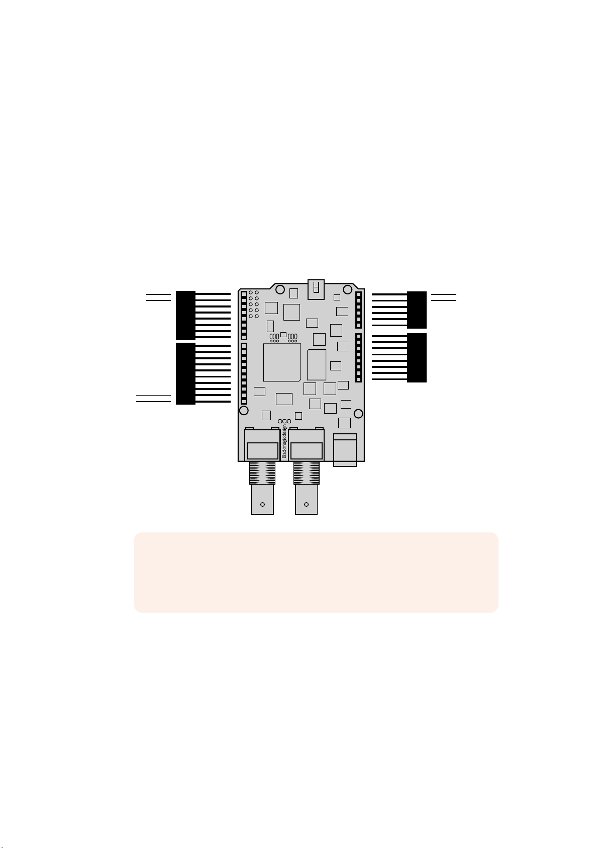
Attaching and Soldering Headers
Your Blackmagic 3G-SDI Shield for Arduino is supplied with 4 stackable headers, including two
8pin headers, a 10 pin, and a 6 pin header. Headers are bridging connectors used to mount
your shield to the Arduino board, and because they are stackable you can attach other shields
on top with additional components, such as control buttons, knobs and joysticks. The header
layout supports mounting to Arduino boards with an R3 footprint, such as the Arduino UNO.
To attach the headers to your shield:
1 Insert the pins of each header through the corresponding pin holes on each side of
your Blackmagic 3G-SDI Shield. Refer to the illustration below for the header layout
arrangement.
0 - Serial RX
1 - Serial TX
(I2C) SDA
(I2C) SCL
2
NOTE When connecting to the shield, communication is via I
2
Werecommend I
C as this enables the serial monitor to be used and makes all
C or Serial.
other pins available. Select the communication mode when defining the
BMDSDIControl object in the sketch. Refer to the ‘Communicating with your
Blackmagic 3G-SDI Shield for Arduino’ section for more information.
A5 (I2C) SCL
A4 (I2C) SDA
2 Solder the base of each header pin to the underside of your shield. Make sure
the solder on each pin creates a firm join with the pin hole, but does not touch
thesolderon nearby pins.
5Getting Started
Page 6
TIP To help make sure all pins on your shield are aligned with the female header pin
slots on the Arduino board, it’s helpful to solder just one pin on each header first.
Nowplace the shield onto the Arduino board to check the pin alignment. If any
headers need adjusting, you can then warm the solder joint on the corresponding
header and improve its alignment. This is a much easier method than soldering all the
joints first and then trying to make adjustments.
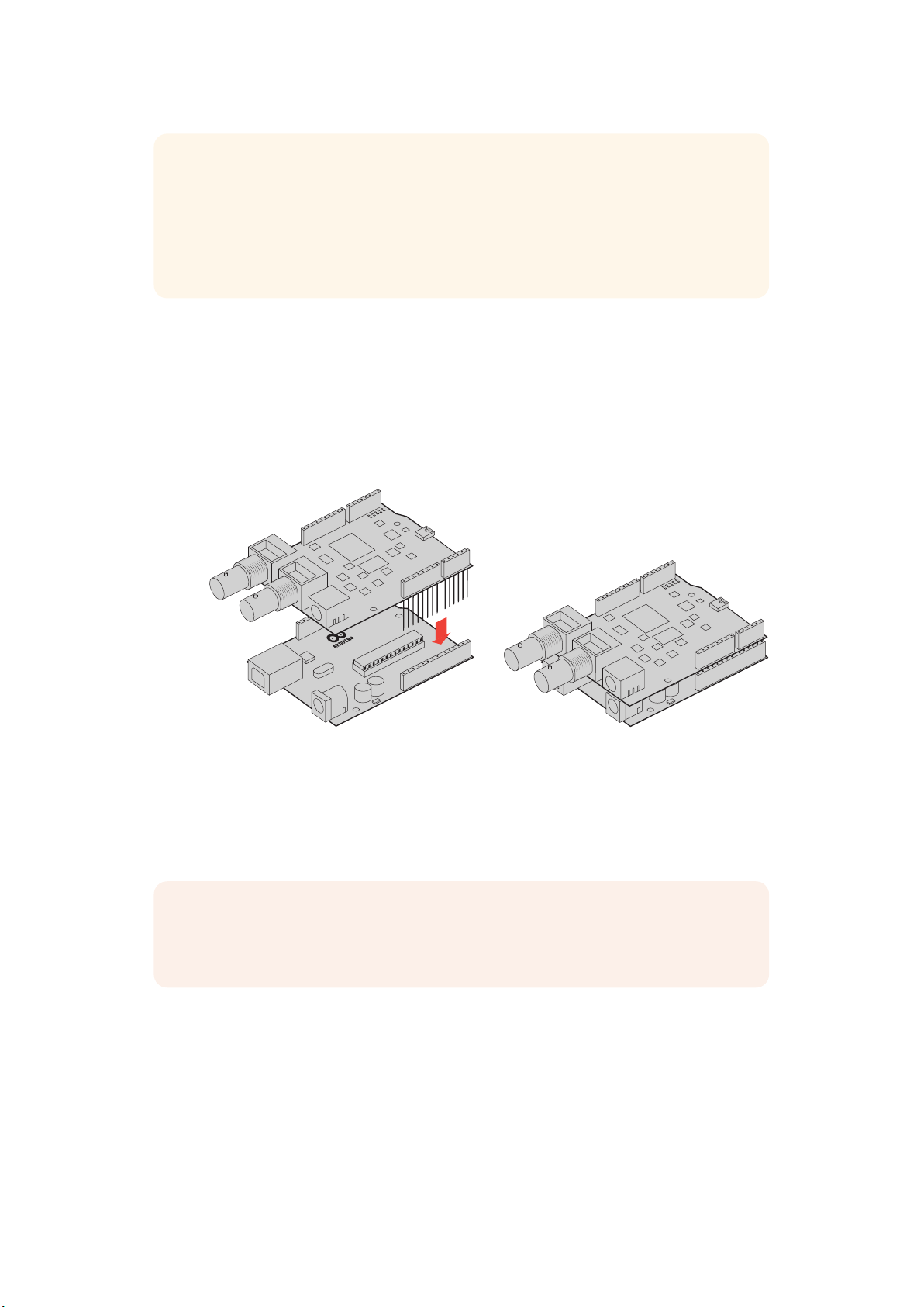
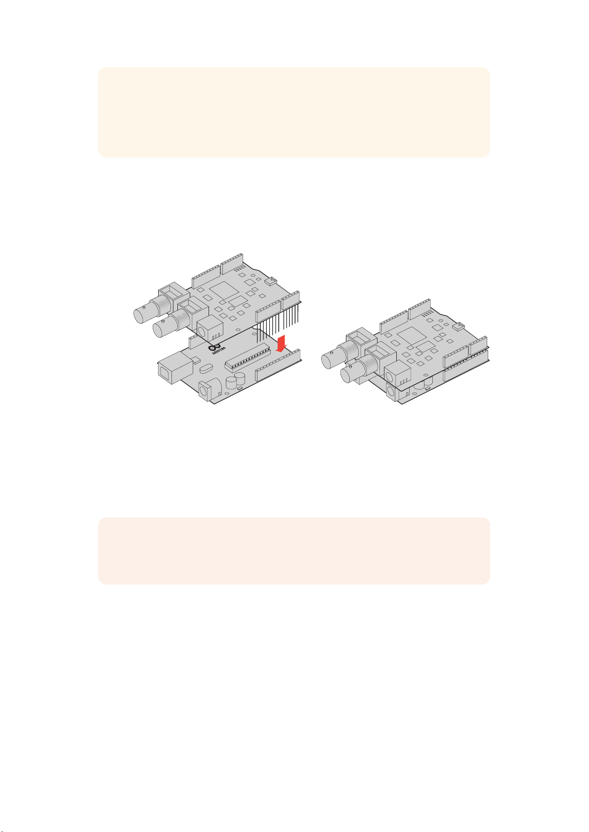
Mounting to the Arduino Board
Now that your headers are soldered to your shield, you can mount the 3G-SDI shield to your
Arduino board.
Carefully holding each side of the shield, align the header pins with your Arduino board’s
headers and gently push the pins into the header slots. Be careful not to bend any of the pins
while mounting the shield.
With all pins plugged in, the connection between the Blackmagic
shield and the Arduino board should be firm and stable.
Plugging in Power
To power your Blackmagic 3G-SDI Shield for Arduino, simply plug in a 12V power adapter into
the 12V power input on your Blackmagic shield.
NOTE Plugging power into the Arduino board will not provide sufficient power to the
Blackmagic shield, however, powering the Blackmagic shield will provide power to the
Arduino as well, so make sure power is connected to your Blackmagic shield only.
6Getting Started
Page 7

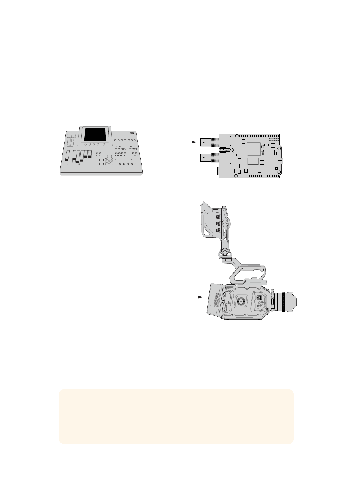
Connecting to SDI Equipment
With power supplied, you can now plug your Blackmagic 3G-SDI Shield into your
SDIequipment. For example, to plug into a switcher and a Blackmagic URSA Mini:
1 Plug the program output from your switcher to the Blackmagic 3G-SDI Shield’s
SDI input.
2 Plug your Blackmagic 3G-SDI Shield’s SDI output into the ‘program’ SDI input marked
PGM on your Blackmagic URSA Mini.
A connection diagram is provided below.
SDI IN
SDI OUT
Switcher
SDI ‘PGM’ Input
Blackmagic 3G-SDI Shield for Arduino
Blackmagic URSA Mini
That’s all there is to getting started!
Now that your shield is mounted to the Arduino board, powered, and connected to your
SDIequipment, you can install the internal software and library files, program the Arduino
software and begin using the shield to control your equipment.
Continue reading the manual for information on how to install the shield’s internal software,
andwhere to install the Arduino library files so the shield can communicate with your Arduino.
TIP You can also use your Blackmagic 3G-SDI Shield for Arduino to control other
Blackmagic Design products, such as Blackmagic MultiView 16. For example, when
your shield is connected to input 16, you can display a tally border on the multi view.
When using Blackmagic URSA Mini cameras, make sure the grid overlay is turned on
toenable the tally display on the camera viewfinder. Refer to your Blackmagic camera
manual for more information.
7Getting Started
Page 8

Software Installation
NOTE Before installing the Blackmagic Shield for Arduino setup utility, download the
latest Arduino IDE software from www.arduino.cc and install it on your computer.
After installing the Arduino software, you can now install your Blackmagic 3G-SDI
Shield’s internal software.
Installing Internal Software
Blackmagic Shield for Arduino Setup is used to update your shield’s internal software. The
internal software communicates with the Arduino board, and controls the board using Arduino
library files. These library files are installed with the setup software and all you need to do is
copy the folder containing the files and paste it into your Arduino application folder. You can
find information about the library files and how to install them in the next section of this manual.
We recommend downloading the latest Blackmagic Shield for Arduino software and updating
your shield so you can benefit from new features and improvements. The latest version can be
downloaded from the Blackmagic Design support center at
www.blackmagicdesign.com/support
To install the internal software using Mac OS X:
1 Download and unzip the Blackmagic Shield for Arduino software.
2 Open the resulting disk image and launch the Blackmagic Shield for Arduino installer.
Follow the on screen instructions.
3 After installing the latest version of Blackmagic Shield for Arduino installer, power your
Blackmagic shield and connect it to your computer via a USB cable.
4 Now launch the setup utility and follow any onscreen prompt to update your shield’s
internal software. If no prompt appears, the internal software is up to date and there is
nothing further you need to do.
To install the internal software using WIndows:
1 Download and unzip the Blackmagic Shield for Arduino software.
2 You should see a Blackmagic Shield for Arduino folder containing this manual and
the Blackmagic Shield for Arduino installer. Double-click the installer and follow the
onscreen prompts to complete the installation.
3 After installing the latest version of the Blackmagic Shield for Arduino installer, power
your Blackmagic shield and connect it to your computer via a USB cable.
4 Now launch the setup utility and follow any onscreen prompt to update your shield’s
internal software. If no prompt appears, the internal software is up to date and there is
nothing further you need to do.
8Software Installation
Page 9

Installing Arduino Library Files
The programs written to control your Arduino are called sketches and your Blackmagic 3G-SDI
Shield for Arduino uses Arduino library files that help make writing sketches easier. After
installing your shield’s setup software, the library files are installed into a folder named ‘Library’.
All you need to do now is copy the folder containing the library files and paste it into your
Arduino libraries folder.
NOTE The Arduino IDE software needs to be closed when installinglibraries.
To install the library files on Mac OS X:
1 Open ‘Blackmagic Shield for Arduino’ in your ‘applications’ folder.
2 Open the ‘Library’ folder and right click/copy the folder named: BMDSDIControl.
3 Now go to your computer’s ‘documents’ folder and open the Arduino folder.
4 You will see a sub-folder named ‘libraries’. Paste the BMDSDIControl folder into the
‘libraries’ folder.
To install the library files on Windows:
1 Open the Programs/ Blackmagic Shield for Arduino folder.
2 You will now see a subfolder named ‘Library’. Open this folder and then right click/copy
the folder named: BMDSDIControl.
3 Now go to your computer’s ‘documents’ folder and open the Arduino folder.
4 You will see a sub-folder named ‘libraries’. Paste the BMDSDIControl folder into the
‘libraries’ folder.
That’s all you need to do to install the Blackmagic Design library files on your computer. When
running the Arduino software, you will now also have Blackmagic Design example sketches to
choose from.
Simply go to the ‘file’ drop down menu in the Arduino software menu bar, and select ‘examples’.
Now select BMDSDIControl and you will see a list of example sketches you can use.
With the library files stored in the correct folder, your shield can now use them to communicate
with the Arduino board. All you need to do is program the Arduino IDE software. Refer to the
‘Programming Arduino Sketches’ section for more information.
NOTE If an updated library file with examples is released in the future, you will need to
delete the old BMDSDIControl folder and replace it with the new folder using the
method described above.
9Installing Arduino Library Files
Page 10

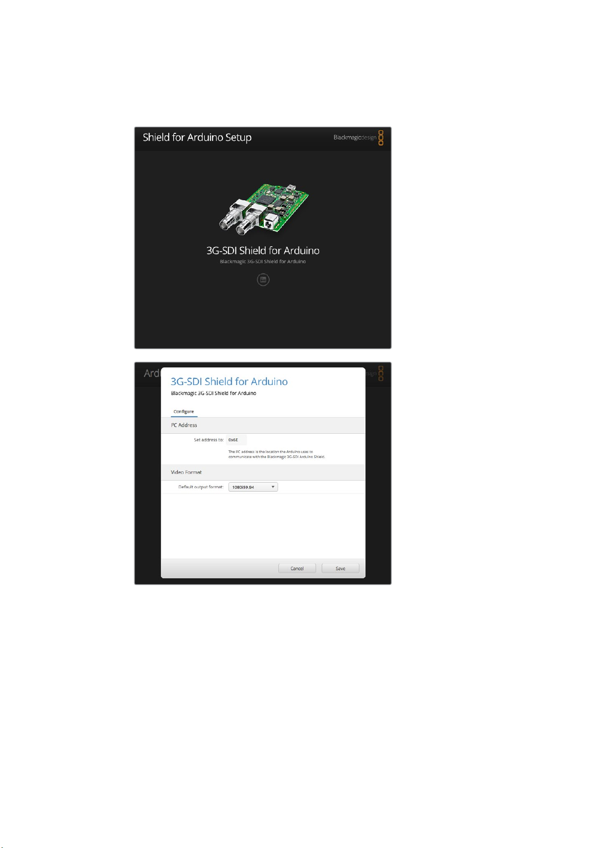
Blackmagic Shield for Arduino Setup
The Blackmagic Shield for Arduino Setup software lets you change
settings on your shield such as the I2C address and video output format.
With Blackmagic Shield for Arduino Setup installed on your computer, you can now change
settings for your shield, such as the ‘I
board can communicate with it, and the ‘video format’, which sets the output format for
your shield.
2
C address’, which identifies your shield so the Arduino
I2C Address
In very rare cases, there is a potential for another shield mounted to your Blackmagic shield to
2
share the same I
occurs, you can change your shield’s default address setting.
C address as your shield’s default address which will create a conflict. If this
10Blackmagic Shield for Arduino Setup
Page 11

The default address for your shield is 0x6E, however, you can choose from a range of
addresses between 0x08 and 0x77.
To change the address for your shield:
1 Launch Blackmagic Shield for Arduino Setup and click on your shield’s ‘settings’ icon.
2 In the ‘set address to:’ edit box, type the address you wish to use.
3 Click ‘save’.
Video Format
The default output format is selected in the setup utility for when no input is connected. When
an input is detected, the output will follow the same format as the input. If this input is removed
the output will revert to the default output format selected in the utility. You can change the
video format by clicking in the ‘default output format’ drop down menu and selecting the
format you want.
You can choose from the following video output formats:
720p50
720p59.94
720p60
1080i50
1080i59.94
1080i60
1080p23.98
1080p24
1080p25
1080p29.97
1080p30
1080p50
1080p59.94
1080p60
Programming Arduino Sketches
The programs, or sketches, written into the Arduino software are very easy to write! Sketches
are written using common ‘C’ programming language. When programming your sketches using
commands from the Studio Camera Control Protocol, the shield embeds these commands into
the SDI output which lets you control your Blackmagic URSA Mini or Blackmagic Studio Cameras.
All supported commands are included in the Studio Camera Control Protocol section of this
manual so you can take the commands from the protocol and use them in your sketch.
11Programming Arduino Sketches
Page 12

Testing your Blackmagic Shield
andLibrary Installation
After everything is connected as described in the ‘Getting Started’ section and you have
installed the setup software and library files, you’ll want to check that your shield is
communicating with the Arduino board and that everything is working as it should.
A fast way is to open and run the supplied tally blink example sketch.
To do this:
1 Launch the Arduino IDE software.
2 Go to the ‘tools’ menu and select the Arduino board and Port number.
3 From the ‘File’ menu, select ‘Examples/BMDSDIControl’ and choose the sketch
named‘TallyBlink’.
4 Upload the sketch to your board.
The Tally Blink example sketch is a fast and easy way to test your Blackmagic 3G-SDI
Shield for Arduino. Rawdata can be sent to your shield via I
the Studio Camera Protocol document, but we have also provided customlibraries to
make programming sketches much easier.
2
C using commands from
12Testing your Blackmagic Shield andLibrary Installation
Page 13

NOTE Make sure your Blackmagic Camera’s tally number is set to 1. Also, ensure the
10 PIN
8 PIN
8 PIN
camera’s grid overlay is turned on to enable the tally display on the camera viewfinder.
Refer to your Blackmagic camera manual for more information.
You should now see the tally light on your Blackmagic Studio Camera blink once every second.
If you see the tally light blinking you can be sure your Blackmagic shield is communicating with
the Arduino and everything is working properly.
If the tally light is not blinking, check that your Blackmagic camera’s tally number is set to 1
andthe camera’s grid overlay is turned on.
If you need further assistance, please visit the Blackmagic Design support center at
www.blackmagicdesign.com/support. Refer to the help section of this manual for more
information on the different ways you can get help setting up your shield.
LED Indicators
Your Blackmagic 3G-SDI Shield for Arduino has six indicator LEDs that confirm activity on your
shield such as power, UART, I
camera control overrides are enabled.
LED 1 - System Active
Illuminates when power is connected to the shield.
LED 2 - Control Overrides Enabled
Illuminates if you have enabled camera control in your Arduino sketch.
LED 3 - Tally Overrides Enabled
Illuminates if you have enabled tally in your Arduino sketch.
2
LED 5 - I
Illuminates when communication is detected between your shield and the Arduino
using the I
C Parser Busy
2
C protocol.
2
C and SPI communication, plus indicators to show when tally and
LED 1
LED 2
LED 3
LED 4
LED 5
LED 6
LED 6 - Serial Parser Busy
Illuminates when UART communication is detected.
When your Blackmagic shield is booting, the power indicator will remain off and LEDs 3, 4 and 5
will indicate the following activity.
LED 3 - Application image loading
LED 4 - EEPROM initializing
LED 5 - Memory check in progress
13Testing your Blackmagic Shield andLibrary Installation
Page 14

After a successful boot, the power LED will turn on and all LEDs will resume their standard
functions during operation.
In the rare case of a boot failure, all LEDs except for the failed activity will flash rapidly so you
can identify the cause of the failure.
Attaching Shield Components
If you want to build your own hardware controller, you can create a new shield with buttons,
knobs and a joystick for more tactile, hands on control. Simply mount the custom shield to your
Blackmagic 3G-SDI Shield for Arduino by plugging it into your shield’s header slots. There is no
limit to the types of controllers you can build. You can even replace the circuitry in an old CCU
with your own custom Arduino solution for an industry standard camera control unit.
You can create your own hardware controller and plug it into your Blackmagic
3G-SDI Shield for Arduino for more interactive and refined control.
Communicating with yourBlackmagic
Shield for Arduino
You can communicate with your Blackmagic 3G-SDI Shield for Arduino via I2C or Serial. We
recommend I
you to use more I
High Level Overview
The library provides two core objects, BMD_SDITallyControlandBMD_SDICameraControl,
which can be used to interface with the shield’s tally and camera control functionalities. Either
or both of these objects can be created in your sketch to issue camera control commands, or
read and write tally data respectively. These objects exist in several variants, one for each of
the physicalI
2
C because of the low pin count and it frees up the serial monitor. This also allows
2
C devices with the shield.
2
C or Serialcommunication busses the shield supports.
14Communicating with yourBlackmagic Shield for Arduino
Page 15

I2C Interface
To use theI2Cinterface to the shield:
// NOTE: Must match address set in the setup utility software
const int shieldAddress = 0x6E;
BMD _ SDICameraControl _ I2C sdiCameraControl(shieldAddress);
BMD _ SDITallyControl _ I2C sdiTallyControl(shieldAddress);
Serial Interface
To use theSerialinterface to the shield:
BMD _ SDICameraControl _ Serial sdiCameraControl;
BMD _ SDITallyControl _ Serial sdiTallyControl;
Note that the library will configure the Arduino serial interface at the required 38400 baud rate.
If you wish to print debug messages to the Serial Monitor when using this interface, change the
Serial Monitor baud rate to match. If the Serial Monitor is used, some binary data will be visible
as the IDE will be unable to distinguish between user messages and shield commands.
Example Usage
Once created in a sketch, these objects will allow you to issue commands to the shield over
selected bus by calling functions on the created object or objects. A minimal sketch that uses
2
the library via the I
// NOTE: Must match address set in the setup utility software
const int shieldAddress = 0x6E;
BMD _ SDICameraControl _ I2C sdiCameraControl(shieldAddress);
BMD _ SDITallyControl _ I2C sdiTallyControl(shieldAddress);
C bus is shown below.
void setup() {
// Must be called before the objects can be used
sdiCameraControl.begin();
sdiTallyControl.begin();
// Turn on camera control overrides in the shield
sdiCameraControl.setOverride(true);
// Turn on tally overrides in the shield
sdiTallyControl.setOverride(true);
}
void loop() {
// Unused
}
The list of functions that may be called on the created objects are listed further on in this
document. Note that before use, you must call the‘begin’function on each object before
issuing any other commands.
Some example sketches demonstrating this library are included in the Arduino
IDE’sFile->Examples->BMDSDIControl menu.
15Communicating with yourBlackmagic Shield for Arduino
Page 16

Studio Camera Control Protocol
This section contains the Studio Camera Control Protocol from the Blackmagic Studio Camera
manual. You can use the commands in this protocol to control supported Blackmagic Design
cameras via your Blackmagic 3G-SDI Shield for Arduino.
The Blackmagic Studio Camera Protocol shows that each camera parameter is arranged in
groups, such as:
Group ID Group
0 Lens
1 Video
2 Audio
3 Output
4 Display
5 Tally
6 Reference
7 Configuration
8 Color Correction
10 Media
11 PTZ Control
The group ID is then used in the Arduino sketch to determine what parameter to change.
The function: sdiCameraControl.writeXXXX, is named based on what parameter you wish to
change, and the suffix used depends on what group is being controlled.
For example sdiCameraControl.writeFixed16 is used for focus, aperture, zoom, audio, display,
tally and color correction when changing absolute values.
The complete syntax for this command is as follows:
sdiCameraControl.writeFixed16 (
Camera num ber,
Gr o u p,
Parameter being controlled,
Operation,
Value
);
The operation type specifies what action to perform on the specified parameter
0 = assign value. The supplied Value is assigned to the specified parameter.
1 = offset value. Each value specifies signed offsets of the same type to be added to the current
parameter Value.
For example:
sdiCameraControl.writeCommandFixed16(
1,
8,
0,
0,
liftAdjust
);
16Studio Camera Control Protocol
Page 17

1 = camera number 1
8 = Color Correction group
0 = Lift Adjust
0 = assign value
liftAdjust = setting the value for the RGB and luma levels
As described in the protocol section, liftAdjust is a 4 element array for RED[0], GREEN[1],
BLUE[2] and LUMA[3]. The complete array is sent with this command.
The sketch examples included with the library files contain descriptive comments to explain
their operation.
Blackmagic SDI Camera Control Protocol
Version 1.3
If you are a software developer you can use the SDI Camera Control Protocol to construct
devices that integrate with our products. Here at Blackmagic Design our approach is to open
upour protocols and we eagerly look forward to seeing what you come up with!
Overview
The Blackmagic SDI Camera Control Protocol is used by ATEM switchers, Blackmagic 3G-SDI
Shield for Arduino and the Blackmagic Camera Control app to provide Camera Control
functionality with supported Blackmagic Design cameras. Please refer to the ‘Understanding
Studio Camera Control’ chapter section of this manual, or the ATEM Switchers Manual
and SDKmanual for more information. These can be downloaded at
www.blackmagicdesign.com/support.
This document describes an extensible protocol for sending a uni directional stream of small
control messages embedded in the non-active picture region of a digital video stream. The
video stream containing the protocol stream may be broadcast to a number of devices. Device
addressing is used to allow the sender to specify which device each message is directed to.
Assumptions
Alignment and padding constraints are explicitly described in the protocol document. Bit fields
are packed from LSB first. Message groups, individual messages and command headers are
defined as, and can be assumed to be, 32 bit aligned.
Blanking Encoding
A message group is encoded into a SMPTE 291M packet with DID/SDID x51/x53 in the active
region of VANC line 16.
Message Grouping
Up to 32 messages may be concatenated and transmitted in one blanking packet up to a
maximum of 255 bytes payload. Under most circumstances, this should allow all messages to
be sent with a maximum of one frame latency.
If the transmitting device queues more bytes of message packets than can be sent in a single
frame, it should use heuristics to determine which packets to prioritize and send immediately.
Lower priority messages can be delayed to later frames, or dropped entirely as appropriate.
Abstract Message Packet Format
Every message packet consists of a three byte header followed by an optional variable length
data block. The maximum packet size is 64 bytes.
17Studio Camera Control Protocol
Page 18

Destination device (uint8)
Command length (uint8)
Command id (uint8)
Device addresses are represented as an 8 bit unsigned integer. Individual
devices are numbered 0 through 254 with the value 255 reserved to indicate
a broadcast message to all devices.
The command length is an 8 bit unsigned integer which specifies the length
of the included command data. The length does NOT include the length of
the header or any trailing padding bytes.
The command id is an 8 bit unsigned integer which indicates themessage
type being sent. Receiving devices should ignore any commands that they do
not understand. Commands 0 through 127 are reserved for commands that
apply to multiple types of devices. Commands 128 through 255 are
device specific.
Reserved (uint8)
Command data (uint8[])
Padding (uint8[])
This byte is reserved for alignment and expansion purposes. Itshould be
set to zero.
The command data may contain between 0 and 60 bytes of data. The format
of the data section is def ined by the command itself.
Messages must be padded up to a 32 bit boundary with 0x0bytes.
Anypadding bytes are NOT included in the command length.
Receiving devices should use the destination device address and or the command identifier to
determine which messages to process. The receiver should use the command length to skip
irrelevant or unknown commands and should be careful to skip the implicit padding as well.
Defined Commands
Command 0 : change configuration
Category (uint8)
Parameter (uint8)
Data type (uint8)
The category number specifies one of up to 256 configuration categories
available on the device.
The parameter number specifies one of 256 potential configuration
parameters available on the device. Parameters 0 through 127 are device
specific parameters. Parameters 128 though 255 are reserved for parameters
that apply to multiple types of devices.
The data type specifies the type of the remaining data. Thepacket length is
used to determine the number of elements in the message. Each message
must contain an integral number of data elements.
Currently defined values are:
A void value is represented as a boolean array of length zero.
0: void / boolean
1: signed byte Data elements are signed bytes
2: signed 16bit integer Data elements are signed 16 bit values
3: signed 32bit integer Data elements are signed 32 bit values
4: signed 64bit integer Data elements are signed 64 bit values
5: UTF-8 string Data elements represent a UTF-8 string with no terminating character.
The data f ield is a 8 bit value with 0 meaning false and all other values
meaning true.
18Studio Camera Control Protocol
Page 19

Data types 6 through 127 are reserved.
Data elements are signed 16 bit integers representing a real number with
5bits for the integer component and 11 bits for the fractional component.
128: signed 5.11fixed point
Thefixed point representation is equal to the real value multiplied by 2^11.
The representable range is from -16.0 to 15.9995
(15 + 2047/2048).
Data types 129 through 255 are available for device specific purposes.
Operation type (uint8)
The operation type specifies what action to perform on the specified
parameter. Currently defined values are:
The supplied values are assigned to the specified parameter. Each element
will be clamped according to its valid range. A void parameter may only be
0: assign value
'assigned' an empty list of boolean type. This operation will trigger the action
associated with that parameter. A boolean value may be assigned the value
zero for false, and any other value for true.
Each value specifies signed offsets of the same type to be added to the
1: offset / toggle value
current parameter values. The resulting parameter value will be clamped
according to their valid range. It is not valid to apply an offset to a void value.
Applying any offset other than zero to a boolean value will invert that value.
Operation types 2 through 127 are reserved.
Operation types 128through 255 are available for device specific purposes.
Data (void)
The data f ield is 0 or more by tes as determined by the data type and number
of elements.
The category, parameter, data type and operation type partition a 24 bit operation space.
Group ID Parameter Type Index Minimum Maximum Interpretation
Lens
0.0 Focus fixed16 – 0 1 0.0 = near, 1.0 = far
0.1 Instantaneous autofocus void – – –
0.2 Aperture (f-stop) fixed16 – -1 16
0.3 Aperture (normalised) fixed16 – 0 1 0.0 = smallest, 1.0 = largest
0.4 Aperture (ordinal) int16 – 0 n
Instantaneous
0.5
auto aperture
0.6 Optical image stabilisation boolean – – –
0.7 Set absolute zoom (mm) int16 – 0 max
Set absolute zoom
0.8
(normalised)
Set continuous
0.9
zoom (speed)
void – – –
fixed16 – 0 1
fixed16 – -1 +1.0
trigger
instantaneous autofocus
Aperture Value (where
fnumber = sqrt(2^AV))
Steps through available
aperture values from
minimum (0) to maximum (n)
trigger instantaneous
auto aperture
true = enabled, false
= disabled
Move to specified focal
length in mm, from minimum
(0) to maximum (max)
Move to specified focal
length: 0.0 = wide, 1.0 = tele
Start/stop zooming at
specified rate: -1.0 = zoom
wider fast, 0.0 = stop,
+1 = zoom tele fast
19Studio Camera Control Protocol
Page 20

Group ID Parameter Type Index Minimum Maximum Interpretation
[0] = frame rate – – 24, 25, 30, 50, 60
[1] = M-rate – – 0 = regular, 1 = M-rate
0 = NTSC,
1 = PAL,
2 = 720,
3 = 1080,
4 = 2k,
5 = 2kDCI,
6 = UHD
0 = progressive, 1 =
interlaced
1 = 100 ISO,
2 = 200 ISO,
4 = 400 ISO,
8 = 800 ISO,
16 = 1600 ISO
Calculate and set
autowhite balance
Use latest auto white
balance setting
Steps through available
exposure valuesfrom
minimum (0) tomaximum (n)
0 = off, 1 = low,
2= medium, 3 = high
fps as integer
(eg 24, 25, 30, 50, 60, 120)
fps as integer, valid when
sensor-off-speed set (eg 24,
25, 30, 33, 48, 50, 60, 120),
no change will beperformed
if this value is set to 0
[1] = sensor-M-rate, valid
whensensor-off-speed-set
0 = Manual Trigger,
1 = Iris,
2 = Shutter,
3 = Iris + Shutter,
4 = Shutter + Iris
Shutter angle in degrees,
multiplied by 100
Shutter speed value as a
fraction of 1, so 50 for 1/50th
of a second
Video
1.0 Video mode int8
1.1 Gain (up to Camera 4.9) int8
1.2 Manual White Balance
1.3 Set auto WB void
1.4 Restore auto WB void
1.5 Exposure (us) int32
1.6 Exposure (ordinal) int16
1.7 Dynamic Range Mode int8 enum
1.8 Video sharpening level int8 enum
1.9 Recording format int16
1.10 Set auto exposure mode int8
1.11 Shutter angle int32
1.12 Shutter speed int32
1.13 Gain int8
1.14 ISO int32
int16
int16
[2] = dimensions – –
[3] = interlaced – –
[4] = Color space – – 0 = YUV
1 16
[0] = color temp 2500 10000 Color temperature in K
[1] = tint -50 50 tint
– – –
– – –
1 42000 time in us
– 0 n
– 0 1 0 = film, 1 = video,
– 0 3
[0] = file
frame rate
[1] = sensor
frame rate
[2] = frame width – – in pixels
[3] = frame height – – in pixels
[4] = flags
– 0 4
– 100 36000
– 24 2000
– -128 127 Gain in decibel (dB)
– 0 2147483647 ISO value
– –
– –
– – [0] = file-M-rate
– –
– – [2] = sensor-off-speed
– – [3] = interlaced
– – [4] = windowed mode
20Studio Camera Control Protocol
Page 21

Group ID Parameter Type Index Minimum Maximum Interpretation
Audio
2.0 Mic level fixed16 – 0 1
2.1 Headphone level fixed16 – 0 1
2.2 Headphone program mix fixed16 – 0 1
2.3 Speaker level fixed16 – 0 1
2.4 Input type int8 – 0 2
[0] ch0 0 1
2.5 Input levels fixed16
[1] ch1 0 1
2.6 Phantom power boolean – – –
3.0 Overlay enables
uint16
bit field
– – –
0.0 = minimum,
1.0 = maximum
0.0 = minimum,
1.0 = maximum
0.0 = minimum,
1.0 = maximum
0.0 = minimum,
1.0 = maximum
0 = internal mic,
1 = line level input,
2 = low mic level input,
3 = high mic level input
0.0 = minimum,
1.0 = maximum
0.0 = minimum,
1.0 = maximum
true = powered,
false = not powered
bit flags:
[0] = display status,
[1] = display frame guides
Some cameras don't allow
separate control of frame
guides and status overlays.
Output
Frame guides style
3.1
(Camera 3.x)
Frame guides opacity
3.2
(Camera 3.x)
Overlays
(replaces .1 and .2
3.3
abovefrom
Cameras 4.0)
int8
fixed16
int8
[0] = frame
guides style
[1] = frame
guide opacity
[0] = frame
guides style
[1] = frame
guide opacity
[2] = safe area
percentage
[3] = grid style – –
0 8
0.1 1
– –
0 100
0 100
0 = HDTV, 1 = 4:3, 2 = 2.4:1,
3 = 2.39:1, 4 = 2.35:1,
5 = 1.85:1, 6 = thirds
0.0 = transparent,
1.0 = opaque
0 = off, 1 = 2.4:1, 2 = 2.39:1,
3 = 2.35:1, 4 = 1.85:1, 5 = 16:9,
6 = 14:9, 7 = 4:3, 8 = 2:1
0 = transparent,
100 = opaque
percentage of full frame
used by safe area guide
(0 means off)
bit flags: [0] = display thirds,
[1] = display cross hairs,
[2] = display center dot
21Studio Camera Control Protocol
Page 22

Group ID Parameter Type Index Minimum Maximum Interpretation
Display
Tal ly
Reference
Configuration
4.0 Brightness fixed16 – 0 1
– – – 0x4 = zebra
4.1 Overlay enables
4.2 Zebra level fixed16 – 0 1
4.3 Peaking level fixed16 – 0 1
Color bars display
4.4
time (seconds)
4.5 Focus Assist int8
5.0 Tally brightness fixed16 – 0 1
5.1 Front tally brightness f ixed16 – 0 1
5.2 Rear tally brightness fixed16 – 0 1
6.0 Source int8 enum – 0 2
6.1 Offset int32 – – – +/- offset in pixels
7.0 Real Time Clock int32
7.1 System language string _ _ _
7.2 Timezone int32 _ _ _ Minutes offset from UTC
7.3 Location int64
int16
bit field
int8 – 0 30
– – – 0x8 = peaking
– – –
[0] = focus
assist method
[1] = focus
line color
[0] time _ _ BCD - HHMMSSFF (UCT)
[1] date _ _ BCD - YYYYMMDD
[0] latitude _ _
[1] longitude _ _
– –
– –
0.0 = minimum,
1.0 = maximum
0.0 = minimum,
1.0 = maximum
0.0 = minimum,
1.0 = maximum
0 = disable bars, 1-30 =
enable bars with timeout (s)
0 = Peak,
1 = Colored lines
0 = Red,
1 = Green,
2 = Blue,
3 = White,
4 = Black
Sets the tally front and tally
rear brightness to the
same level.
0.0 = minimum,
1.0 = maximum
Sets the tally front
brightness.
0.0 = minimum,
1.0 = maximum
Sets the tally rear brightness.
0.0 = minimum,
1.0 = maximum
Tally rear brightness cannot
be turned off
0 = internal,
1 = program,
2 = external
ISO-639 -1 two character
language code
BCD - s0DDdddddddddddd
where s is the sign:
0 = north (+), 1 = south (-);
DD degrees, dddddddddddd
decimal degrees
BCD - sDDDdddddddddddd
where s is the sign: 0 = west
(-), 1 = east (+); DDD degrees,
dddddddddddd
decimal degrees
22Studio Camera Control Protocol
Page 23

Group ID Parameter Type Index Minimum Maximum Interpretation
[0] red -2 2 default 0.0
8.0 Lift Adjust fixed16
8.1 Gamma Adjust fixed16
8.2 Gain Adjust fixed16
Color
Correction
8.3 Offset Adjust f ixed16
8.4 Contrast Adjust fixed16
8.5 Luma mix fixed16 – 0 1 default 1.0
8.6 Color Adjust f ixed16
8.7 Correction Reset Default void – – – reset to defaults
[1] green -2 2 default 0.0
[2] blue -2 2 default 0.0
[3] luma -2 2 default 0.0
[0] red -4 4 default 0.0
[1] green -4 4 default 0.0
[2] blue -4 4 default 0.0
[3] luma -4 4 default 0.0
[0] red 0 16 default 1.0
[1] green 0 16 default 1.0
[2] blue 0 16 default 1.0
[3] luma 0 16 default 1.0
[0] red -8 8 default 0.0
[1] green -8 8 default 0.0
[2] blue -8 8 default 0.0
[3] luma -8 8 default 0.0
[0] pivot 0 1 default 0.5
[1] adj 0 2 default 1.0
[0] hue -1 1 default 0.0
[1] sat 0 2 default 1.0
23Studio Camera Control Protocol
Page 24

Group ID Parameter Type Index Minimum Maximum Interpretation
0 = RAW,
[0] = basic codec – –
– –
1 = DNxHD,
2 = ProRes,
3 = Blackmagic RAW
RAW:
0 = Uncompressed,
1 = lossy 3:1,
2 = lossy 4:1
Media
10.0 Codec
10.1 Transport mode int8
int8
enum
– –
[1] = codec variant
– –
[0] = mode – –
[1] = speed – –
[2] = flags – –
[3] = slot 1 storage
medium
– –
ProRes:
0 = HQ,
1 = 422,
2 = LT, 3 = Proxy,
4 = 444, 5 = 444XQ
Blackmagic RAW:
0 = Q0,
1 = Q5,
2 = 3:1,
3 = 5:1,
4 = 8:1,
5 = 12:1
0 = Preview,
1 = Play,
2 = Record
-ve = multiple speeds
backwards,
0 = pause,
+ve = multiple
speeds forwards
1<<0 = loop,
1<<1 = play all,
1<<5 = disk1 active,
1<<6 = disk2 active,
1<<7 = time-lapse recording
0 = CFast card,
1 = SD,
2 = SSD Recorder
PTZ
Control
11.0
Pan/Tilt Velocity fixed 16
11.1 Memory Preset
int8 enum
int8
[4] = slot 2 storage
medium
[0] = pan velocity -1.0 1.0
[1] = tilt velocity -1.0 1.0
[0] =
preset command
[1] =
preset slot
– –
– –
0 5 –
0 = CFast card,
1 = SD,
2 = SSD Recorder
-1.0 = full speed left,
1.0 = full speed right
-1.0 = full speed down,
1.0 = full speed up
0 = reset,
1 = store location,
2 = recall location
24Studio Camera Control Protocol
Page 25

Example Protocol Packets
Packet
Operation
Length Byte
0 1 2 3 4 5 6 7 8 9 10 11 12 13 14 15
header command data
length
destination
trigger instantaneous
auto focus on camera 4
turn on OIS on all cameras 12 255 5 0 0 0 6 0 0 1 0 0 0
set exposure to 10 ms on
camera 4 (10 ms = 10000
us = 0x00002710)
add 15% to zebra level
(15 % = 0.15 f = 0x0133 fp)
select 1080p 23.98 mode on
all cameras
subtract 0.3 from gamma
adjust for green & blue
(-0.3 ~= 0xfd9a fp)
8 4 4 0 0 0 1 0 0
12 4 8 0 0 1 5 3 0 0x10 0x27 0x00 0x00
12 4 6 0 0 4 2 128 1 0x33 0x01 0 0
16 255 9 0 0 1 0 1 0 24 1 3 0 0 0 0 0
16 4 12 0 0 8 1 128 1 0 0 0x9a 0xfd 0x9a 0xfd 0 0
command
category
reserved
type
parameter
operation
all operations combined 76 4 4 0 0 0 1 0 0 255 5 0 0 0 6 0 0
1 0 0 0 4 8 0 0 1 5 3 0 0x10 0x27 0x00 0x00
4 6 0 0 4 2 128 1 0x33 0x01 0 0 255 9 0 0
1 0 1 0 24 1 3 0 0 0 0 0 4 12 0 0
8 1 128 1 0 0 0x9a 0xfd 0x9a 0xfd 0 0
25Studio Camera Control Protocol
Page 26

Developer Information
This section of the manual provides all the details you will need if you want to write custom
libraries and develop your own hardware for your Blackmagic 3G-SDI Shield for Arduino.
Physical Encoding - I2C
The shield operates at the following I2C speeds:
1. Standard mode (100 kbit/s)
2. Full speed (400 kbit/s)
2
The default 7-bit shield I
Shield Pin | Function
--------------------- |---------------------------- A4 | Serial Data (SDA)
A5 | Serial Clock (SCL)
2
C Protocol (Writes):**
**I
(START W) [REG ADDR L] [REG ADDR H] [VAL] [VAL] [VAL] ... (STOP)
2
C Protocol (Reads):**
**I
(START W) [REG ADDR L] [REG ADDR H] ... (STOP) (START R) [VAL] [VAL] [VAL] ... (STOP)
The maximum payload (shown as **VAL** in the examples above) read/write length (following
the internal register address) in a single transaction is 255 bytes.
C slave address is 0x6E.
Physical Encoding - UART
The shield operates with a UART baud rate of 115200, 8-N-1 format.
Shield Pin | Function
--------------------- |---------------------------- IO1 | Serial Transmit (TX)
IO0 | Serial Receive (RX)
**UART Protocol (Writes):**
[0xDC] [0x42] [REG ADDR L] [REG ADDR H] [‘W’] [LENGTH] [0x00] [VAL] [VAL] [VAL] ...
**UART Protocol (Reads):**
[0xDC] [0x42] [REG ADDR L] [REG ADDR H] [‘R’] [LENGTH] [0x00] [VAL] [VAL] [VAL] ...
The maximum payload (shown as **VAL** in the examples above) read/write length (specified in
the **LENGTH** field) in a single transaction is 255 bytes.
Register Address Map
26Developer Information
Page 27

The shield has the following user address register map:
Address | Name | R/W | Register Description
--------------------- |----------- |----- |-------------------------------
0x0000 - 0x0003 | IDENTITY | R | Hardware Identifier
0x0004 - 0x0005 | HWVERSION | R | Hardware Version
0x0006 - 0x0007 | FWVERSION | R | Firmware Version
| | |
0x1000 | CONTROL | R/W | System Control
| | |
0x2000 | OCARM | R/W | SDI Control Override Arm
0x2001 | OCLENGTH | R/W | SDI Control Override Length
0x2100 - 0x21FE | OCDATA | R/W | SDI Control Override Data
| | |
0x3000 | ICARM | R/W | SDI Control Incoming Arm
0x3001 | ICLENGTH | R | SDI Control Incoming Length
0x3100 - 0x31FE | ICDATA | R | SDI Control Incoming Data
| | |
0x4000 | OTARM | R/W | SDI Tally Override Arm
0x4001 | OTLENGTH | R/W | SDI Tally Override Length
0x4100 - 0x41FE | OTDATA | R/W | SDI Tally Override Data
| | |
0x5000 | ITARM | R/W | SDI Tally Incoming Arm
0x5001 | ITLENGTH | R | SDI Tally Incoming Length
0x5100 - 0x51FE | ITDATA | R | SDI Tally Incoming Data
All multi-byte numerical fields are stored little-endian. Unused addresses are reserved and read
back as zero.
Register: IDENTITY (Board Identifier)
[ IDENTITY ]
31 0
**Identity:** ASCII string ‘SDIC’ (i.e. `0x43494453`) in hexadecimal.
Register: HWVERSION (Hardware Version)
[ VERSION MAJOR ] [ VERSION MINOR ]
15 8 7 0
**Version Major:** Hardware revision, major component.
**Version Minor:** Hardware revision, minor component.
Register: FWVERSION (Firmware Version)
[ VERSION MAJOR ] [ VERSION MINOR ]
15 8 7 0
**Version Major:** Firmware revision, major component.
**Version Minor:** Firmware revision, minor component.
Register: CONTROL (System Control)
[ RESERVED ] [ OVERRIDE OUTPUT ] [ RESET TALLY ] [ OVERRIDE TALLY ] [
OVERIDE CONTROL ]
7 4 3 2 1 0
27Developer Information
Page 28

**Reserved:** Always zero.
**Override Output:** When 1, the input SDI signal (if present) is discarded and the
shield generates its own SDI signal on the SDI output
connector. When 0, the input signal is passed through to the
output if present, or the shield generates its own SDI
signal if not.
**Reset Tally:** When 1, the last received incoming tally data is immediately copied
over to the override tally data register. Automatically cleared
by hardware.
**Override Tally:** When 1, tally data is overridden with the user supplied data.
When 0, input tally data is passed through to the output
unmodified.
**Override Control:** When 1, control data is overridden with the user supplied
data. When 0, input control data is passed through to the
output unmodified.
Register: OCARM (Output Control Arm)
[ RESERVED ] [ ARM ]
7 1 0
**Reserved:** Always zero.
**Arm:** When 1, the outgoing control is data armed and will be sent in the
next video frame. Automatically cleared once the control has
been sent.
Register: OCLENGTH (Output Control Length)
[ LENGTH ]
7 0
**Length:** Length in bytes of the data to send in OCDATA.
Register: OCDATA (Output Control Payload Data)
[ CONTROL DATA ]
255*8-1 0
**Control Data:** Control data that should be embedded into a future video frame.
Register: ICARM (Incoming Control Arm)
[ RESERVED ] [ ARM ]
7 1 0
**Reserved:** Always zero.
**Arm:** When 1, incoming control data is armed and will be received in the
next video frame. Automatically cleared once a control packet has
been read.
Register: ICLENGTH (Incoming Control Length)
[ LENGTH ]
7 0
**Length:** Length in bytes of the data in _ICDATA_. Automatically set when a
new packet has been cached.
28Developer Information
Page 29

Register: ICDATA (Incoming Control Payload Data)
[ CONTROL DATA ]
255*8-1 0
**Control Data:** Last control data extracted from a video frame since _ICARM.ARM_
was reset.
Register: OTARM (Output Tally Arm)
[ RESERVED ] [ ARM ]
7 1 0
**Reserved:** Always zero.
**Arm:** When 1, the outgoing tally data is armed and will be continuously from
the next video frame until new data is set. Automatically cleared once
the tally has been sent in at least one frame.
Register: OTLENGTH (Output Tally Length)
[ LENGTH ]
7 0
**Length:** Length in bytes of the data to send in OTDATA.
Register: OTDATA (Output Tally Data)
[ TA LLY DATA ]
255*8-1 0
**Tally Data:** Tally data that should be embedded into a future video frame (one
byte per camera). Bit zero indicates a Program tally, while bit one
indicates a Preview tally.
Register: ITARM (Input Tally Arm)
[ RESERVED ] [ ARM ]
7 1 0
**Reserved:** Always zero.
**Arm:** When 1, tally data armed and will be received in the next video frame.
Automatically cleared once the tally has been read.
Register: ITLENGTH (Input Tally Length)
[ LENGTH ]
7 0
**Length:** Length in bytes of the data in _ITDATA_. Automatically set when a
new packet has been cached.
Register: ITDATA (Input Tally Data)
[ TA LLY DATA ]
255*8-1 0
**Tally Data:** Last tally data extracted from a video frame since _ITARM.ARM_ was
reset (one byte per camera). Bit zero indicates a Program tally, while
bit one indicates a Preview tally.
29Developer Information
Page 30

Help
Getting Help
Your Blackmagic 3G-SDI Shield for Arduino is a developers tool designed for you to develop
independently based on your custom requirements.
For the most up to date information about your shield, visit the Blackmagic Design online
support pages and check the latest support material.
Blackmagic Design Online Support Pages
The latest manual, software and support notes can be found at the Blackmagic Design support
center at www.blackmagicdesign.com/support.
Arduino Development Forum
If you have programming questions, you can get help from Arduino development forums on the
Internet. There is a whole community of Arduino developers and many good quality forums
where you can ask software questions, or even find a willing engineer to hire to implement your
solution for you!
Blackmagic Design Forum
The Blackmagic Design forum on our website is a helpful resource you can visit for more
information and creative ideas. This can also be a faster way of getting help as there may
already be answers you can find from other experienced users and Blackmagic Design staff
which will keep you moving forward. You can visit the forum at
https://forum.blackmagicdesign.com
Checking the Software Version Currently Installed
To check which version of Blackmagic 3G-SDI Shield for Arduino Setup software is installed on
your computer, open the About Blackmagic 3G-SDI Shield for Arduino Setup window.
On Mac OS X, open Blackmagic 3G-SDI Shield for Arduino Setup from the Applications
folder. Select About Blackmagic Shield for Arduino Setup from the application menu to
reveal theversion number.
On Windows 7, open Blackmagic 3G-SDI Shield for Arduino Setup from your Start
menu. Clickonthe Help menu and select About Blackmagic 3G-SDI Shield for Arduino
Setup to reveal the version number.
On Windows 8, open Blackmagic 3G-SDI Shield for Arduino Setup from the Blackmagic
3G-SDI Shield for Arduino Setup tile on your Start page. Click on the Help menu and
select About Blackmagic Shield for Arduino Setup to reveal the version number.
How to Get the Latest Software Updates
After checking the version of Blackmagic 3G-SDI Shield for Arduino Setup software installed
on your computer, please visit the Blackmagic Design support center at
www.blackmagicdesign.com/support to check for the latest updates. While it is usually a
goodidea to run the latest updates, it is wise to avoid updating any software if you are in
themiddle of an important project.
30Help
Page 31

Warranty
12 Month Limited Warranty
Blackmagic Design warrants that the Blackmagic 3G-SDI Shield for Arduino product will be free
from defects in materials and workmanship for a period of 12 months from the date of purchase.
If a product proves to be defective during this warranty period, Blackmagic Design, at its option,
either will repair the defective product without charge for parts and labor, or will provide a
replacement in exchange for the defective product.
In order to obtain service under this warranty, you the Customer, must notify Blackmagic Design
of the defect before the expiration of the warranty period and make suitable arrangements for the
performance of service. The Customer shall be responsible for packaging and shipping the
defective product to a designated service center nominated by Blackmagic Design, with shipping
charges pre paid. Customer shall be responsible for paying all shipping changes, insurance, duties,
taxes, and any other charges for products returned to us for any reason.
This warranty shall not apply to any defect, failure or damage caused by improper use or improper
or inadequate maintenance and care. Blackmagic Design shall not be obligated to furnish service
under this warranty: a) to repair damage resulting from attempts by personnel other than
Blackmagic Design representatives to install, repair or service the product, b) to repair damage
resulting from improper use or connection to incompatible equipment, c) to repair any damage or
malfunction caused by the use of non Blackmagic Design parts or supplies, or d) to service a
product that has been modified or integrated with other products when the effect of such a
modification or integration increases the time or difficulty of servicing the product. THIS WARRANTY
IS GIVEN BY BLACKMAGIC DESIGN IN LIEU OF ANY OTHER WARRANTIES, EXPRESS OR IMPLIED.
BLACKMAGIC DESIGN AND ITS VENDORS DISCLAIM ANY IMPLIED WARRANTIES OF
MERCHANTABILITY OR FITNESS FOR A PARTICULAR PURPOSE. BLACKMAGIC DESIGN’S
RESPONSIBILITY TO REPAIR OR REPLACE DEFECTIVE PRODUCTS IS THE WHOLE AND EXCLUSIVE
REMEDY PROVIDED TO THE CUSTOMER FOR ANY INDIRECT, SPECIAL, INCIDENTAL OR
CONSEQUENTIAL DAMAGES IRRESPECTIVE OF WHETHER BLACKMAGIC DESIGN OR THE
VENDOR HAS ADVANCE NOTICE OF THE POSSIBILITY OF SUCH DAMAGES. BLACKMAGIC
DESIGN IS NOT LIABLE FOR ANY ILLEGAL USE OF EQUIPMENT BY CUSTOMER. BLACKMAGIC
IS NOT LIABLE FOR ANY DAMAGES RESULTING FROM USE OF THIS PRODUCT. USER OPERATES
THIS PRODUCT AT OWN RISK.
© Copyright 2020 Blackmagic Design. All rights reserved. ‘Blackmagic Design’, ‘DeckLink’, ‘HDLink’, ‘Workgroup Videohub’,
‘Videohub’, ‘DeckLink ’, ‘Intensity’ and ‘Leading the creative video revolution’ are registered trademarks in the US and other
countries. A ll other compa ny and product names may be trad e marks of their respec tive compan ies with whic h they are associated.
Arduinoand the Arduino logo are trademarks of Arduino. Thunderbolt and the Thunderbolt logo are trademarks of Intel Corporation
in the U.S. and/or other countries.
31Warranty
Page 32

インストール/オペレーションマニュアル
Blackmagic
3G-SDI Shield
for Arduino
2020年2
日本語
月
32
Page 33

ようこそ
このたび は 新しいBlackmagic3G
ござ いました 。
私たちは常に新しいテクノロジーに関心を持っており、弊社の
いることを非 常に 嬉しく思っていま す。3G
ワークフローに組み込んで、より多くのコントロールオプションを
きま す。
例えば、
SDI
信 号 に エ ンベッドし た デ ー タパ ケ ット 経 由 で 、
MiniやBlackmagicStudioCamera
に
Blackmagic
コントロールソリューションを構 築 できます。同シールドは
スイッチャーからのプログラムリターンフィードを、シールドを通じて
入 力 に ル ープ で き ま す。
カメラへのコマンド送信用のコードは簡単に書くことができ、すべての対応コマンドがこのマニュアル
に記 載 さ れていま す。
また、コンピューターからカメラのコントロールも可能です。あるいは、ボタン、ノブ、ジョイスティック
をシールドに追 加して、ダイナミックなハードウェアコントローラー を構築することで、レンズフォーカ
ス/ズーム、アパーチャー設 定、ペデ スタルおよびホワイトバランスコントロール、カメラのパワフルな内
蔵カラーコレクターなどの機 能を調 整することも可能です。独自のカスタムコントローラーはプロダク
シ ョ ン で 便 利 な だ け で な く 、開 発 自 体 も 面 白 い 作 業 で す !
カメラをコントロールしたい場 合は、
-
SDIShieldforArduinoをお買い求めいただき誠にありがとう
SDI
製品がクリエイティブに使用されて
-
SDIShieldforArduinoを使用すれば、ArduinoをSDI
BlackmagicDesign
ATEM
スイッ チ ャ ー か ら
を コ ン ト ロ ー ル で き ま す 。ま た 、
3G-SDIShieldforArduino
SDI
プ ラ ットフ ォ ー ム として 使 用 で き る の で 、
ATEM
スイッチャーを使用せず
Blackmagic
製品に追加で
BlackmagicURSA
を 使 って カ ス タム
カメラ の プ ロ グラム
このテクノロジーは拡張 性が高く、多くの使 用方法が 考えられます。
ルドした際には、その内容をぜひお聞かせください!
このマニュ アル には 、
て 記 載 さ れ て い ま す 。弊 社 ウ ェ ブ サ イ ト
マニュアル の最 新 バー ジョンを確 認し、シールドの内部ソフトウェアをアップ デ ートしてください 。ソフ
トウェアをアップ デ ートすることで、常に最 新 の 機 能 をお使い いただけ ます。ソフトウェアを ダ ウンロー
ドする際にユーザー登 録していただければ、新しいソフトウェアのリリース時にお知らせいたします。
常に新機能の開発および製品の改善に努めていますので、ユーザーの皆様からご意見をいただければ
幸いです。
BlackmagicDesignCEO
グ ラ ン ト・ペ テ ィ
Blackmagic3G-SDIShieldforArduinoを使用する上で必要な情報がすべ
www.blackmagicdesign.com/jp
SDI
コント ロ ー ラ ー を カ スタムビ
のサポートページでこの
Page 34

目次
Blackmagic3G-SDIShieldforArduino
はじめに 35
ヘッダーの取り付けおよびはんだ付け 35
Arduino
電源の接続 36
SDI
ソフトウェアのインストール 38
内 蔵 ソフトウェアの インストール 38
ボードへのマウント 36
機器への接続 37
Arduinoライブラリファイルのインストール 39
BlackmagicShieldforArduinoSetup 40
2
Cアドレス 40
I
ビデオフォーマット 41
Arduinoスケッチのプログラミング 41
BlackmagicShieldのテストとライブラリの インストール 42
インジケーター 43
LED
シールドコンポーネントの取り付け 44
CommunicatingwithyourBlackmagicShieldforArduino 44
LevelOverview 44
High
I2CInterface
SerialInterface
ExampleUsage
45
45
45
StudioCameraControlProtocol 46
Blackmagic
Overview
Assumptions
BlankingEncoding
MessageGrouping
AbstractMessagePacketFormat
DefinedCommands
SDICameraControlProtocol 47
47
47
47
47
47
48
ExampleProtocolPackets 55
DeveloperInformation 56
PhysicalEncoding-I2C
PhysicalEncoding-UART
ヘルプ 60
保証 61
56
56
Page 35
はじめに
6 PIN
8 PIN
ヘッダーの取り付けおよびはんだ付け
Blackmagic3G-SDIShieldforArduinoに は 、積 み 重 ね 可 能 な 4つの ヘッ ダー が 同 梱 されて い ます。8ピン
ヘッダー が2つ 、そ し て10ピン
するため のブリッジコネクターです。積み重ねられるので、コントロールボタンやノブ、ジョイスティックなどの
追加コンポーネントの付いた別のシールドをさらに取り付けることが可能です。ヘッダーレイアウトは、
UNOなど、R3フットプリントのArduinoボードへ のマウントをサポートします。
ヘッダーをシールドに取り付ける:
1
各 ヘ ッ ダ ー の ピ ン を 、
に差し 込 みま す。ヘッダーレ イアウトの 配 置 に 関 して は 、以 下 の 図 を 参 照してください 。
-
0
SerialRX
1-
SerialTX
/
6
ピ ンヘッダー が1つ ず つ で す 。ヘ ッ ダ ー は 、
Arduino
ボードにシールド をマウント
Arduino
Blackmagic3G-SDIShieldシールドの各サイドにある 、対応するピンホール
2
(
I
A5
C
(
I2C
A4
)
)
SCL
SDA
2
(
)
I
C
SDA
2
)
(
C
I
SCL
メモ シ ー ル ド と 接 続 す る 際 、通 信 は
I2C
あるいはシリアル 経 由 で す。
I2C
はシリアル モ ニタ
ーを有 効 にして、すべてのピンを使 用 できるため、これを推 奨します。スケッチで
BMDSDIControlオブジェクトを設定する際に通信モードを選択します。詳細は、
「BlackmagicShieldforArduinoとの通信」セクションを参照してください。
2
各ヘッダーピンの底部をシールドの下面にはんだ付けします。各ピンのはんだがピンホールに
しっかり接合され 、周辺のピンに触れていないことを確認します。
はじめに
35
Page 36
作業のこつシールド上のすべ てのピ ン が
致するように 、各ヘッダーで1つのピン だけを最初にはんだ付けするとよいでしょう。その後、シールド
を
Arduino
対応するヘッダーのはんだの接合部を温めて配置を調整します。この方法は、最初にすべてのピンを
接 合 して し ま って か ら 調 整 す る よ り ず っ と 簡 単 で す。
ボードの上に配置してピンの配置を確 認します。ヘッダーを調 整する必要がある場合は、
Arduino
ボ ー ド の メ ス の ヘ ッ ダ ー ピ ン ・ス ロ ッ ト と 確 実 に 一
Arduino
ヘッダーをシールドにはんだ付けしたら、次はこの3G
シールドの両サイドを注意深く持ち、ヘッダーピンを
トへゆっくりと差し込みます。シールドをマウントする際に、ピンが 曲がらないように注意してください。
ボードへ のマ ウント
すべてのピンが差し込まれると、
Arduino
ボードはしっかりと接続され固定されます。
Blackmagic
-
SDIシールドを Arduinoボード に マ ウ ントしま す。
Arduino
シールドと
ボードのヘッダーと揃えてピンをヘッダースロッ
電源の接続
Blackmagic3G-SDIShield for Arduinoに電源を入れるには、12V電 源アダプターをBlackmagicシール
12V電 源 入 力に 差 し 込 み ま す。
ドの
メモ
Arduino
が、Blackmagicシールドに電源を接続すればArduinoボードにも給電されるので、電源が
ボードに電源を接続しても、
Blackmagic
シールドには十分な電力が 供給されません
Blackmagicシールドに接続されていることを確認してください。
はじめに
36
Page 37
機器への接続
SDI
電源を接続したら、次にBlackmagic3G
機 器 に 接 続 します。
1
スイッ チ ャ ー か ら の プ ロ グ ラム 出 力 を
2
Blackmagic3G-SDIShieldのSDI
に接 続しま す。
以下の接続図を参照してください。
Switcher
-
SDIShieldを スイッ チ ャ ー と BlackmagicURSAMiniなどのSDI
Blackmagic3G-SDIShieldのSDI入 力 に 接 続しま す。
出力を
BlackmagicURSAMini
SDI IN
SDI OUT
のプ ログラム
Blackmagic 3G-SDI Shield for Arduino
SDI
入 力(
PGM
)
SDI ‘PGM’ Input
Blackmagic URSA Mini
最初に必要な作業はこれだけです!
ここまでの 作 業 で シ ールドが
部ソフトウェアおよびライブラリファイル の インストール、
り、シールドを使ったコントロールを開 始できます。
シールドと
ライブ ラリファイルのインストール 場 所に関しては 、同 マニュアルを読み進めてください 。
Arduino
作業のこつ
を通 信 可能にするためのシールドの内 部ソフトウェアのインストール方法および
Blackmagic3G-SDIShieldforArduinoは、BlackmagicMultiView16などの 他
BlackmagicDesign
ると、マルチビューでタリーボーダーを表示できます。
合、カメラのビューファインダーでタリー表示を有効にするには、グリッドオーバーレイをオンにしてく
だ さ い 。詳 細 は 、Blackmagicカメラマニュアルを参照してください。
Arduino
製品をコントロールすることもできます。例えば、シールドを入 力16に接続す
ボードにマウントされ、電 源および
Arduino
ソフトウェアのプログラム作成が可能とな
BlackmagicURSAMini
SDI
機 器 に 接 続 さ れ ま し た 。こ れ で 内
カメラ を 使 用 する 場
Arduino
はじめに
37
Page 38

ソフトウェアの インストール
メモ BlackmagicShieldforArduinoSetupUtilityの イ ン ス ト ー ル 前 に 、最 新 の ArduinoIDE
ソフトウェアを www
さい。
.
arduino.ccからダウンロードして、コ ンピュー ター にインストール してくだ
Arduino
トー ルで きます。
ソフトウェアの インストール 後 、
Blackmagic3G-SDIShield
の内 部 ソフトウェア を インス
内 蔵 ソフトウェアの インストール
BlackmagicShieldforArduinoSetupを使ってシールドの内部ソフトウェアをアップデートできます。内 部
ソフトウェアは
れらのライブラリファイルは、セットアップソフトウェア で インストールできます。必 要 な 作 業 は 、ファイル を 含
むフォルダーをコピーして、Arduinoアプ リケー ションフォルダー に ペーストするだけです。この マニュアル の 次
セクションで、ライブラリファイルおよび そのインストール方法に関して説 明します。
新しい機能および改良機能を使用できるよう、最新の
ンロードしてシールドをアップデートすることをお 勧 めします。最 新 バー ジョンは 、
ー ト セ ン タ ー( www
MacOSXで 内 部 ソ フトウ ェ ア を イ ンス ト ー ル す る:
1
2
3
最 新バージョンの BlackmagicShieldforArduinoInstallerをインストールしたら 、Blackmagic
4
Arduino
ボードと 通 信し、
Arduino
ライブ ラリファイルを使ってボードをコントロールしま す。こ
BlackmagicShieldfor Arduinoソフトウェ ア を ダウ
BlackmagicDesign
.
blackmagicdesign.com/jp/support)で ダ ウ ン ロ ー ド で き ま す 。
BlackmagicShieldforArduinoソフトウェアを ダ ウ ン ロ ードして解 凍 します。
ディス ク イメ ー ジ を 開 いて
指 示 に 従 ってく だ さ い 。
シールドの電 源 を入れて、USBケーブルで コンピュー ターと 接 続 します。
SetupUtility
内蔵ソフトウェアが最新で何もする必要がない場合、指示は表示されません。
を起 動し、スクリーンの指示に従ってシールドの内部ソフトウェアをアップデートします。
BlackmagicShieldforArduinoInstaller
を 起 動 し ま す 。ス ク リ ー ン 上 の
サポ
WIndowsで 内 部 ソ フ ト ウェ ア を イ ン スト ー ル す る:
1
BlackmagicShieldforArduinoソフトウェアを ダ ウ ン ロ ードして解 凍 します。
2
このマニュアル お よび BlackmagicShieldforArduinoInstallerを含むBlackmagicShieldfor
Arduino
ってイ ン スト ー ル し ま す 。
3
最 新バージョンの
シールドの電 源 を入れて、USBケーブルで コンピュー ターと 接 続 します。
4
SetupUtility
内蔵ソフトウェアが最新で何もする必要がない場合、指示は表示されません。
フォルダーが確認できます。インストーラーをダブルクリックし、画面に表示される指示に従
BlackmagicShieldforArduinoInstallerをインストールしたら、Blackmagic
を起 動し、スクリーンの指示に従ってシールドの内部ソフトウェアをアップデートします。
ソフトウェアの インスト ー ル
38
Page 39

Arduinoライブラリファイルのインストール
Arduino
forArduino
ットアップ ソフトウェ ア をインストールした ら 、ラ イブラリファイル は「
ンストールされます。必 要な作業は、ライブラリファイルを含むフォルダーをコピーして、
フォルダーにペーストするだけです。
をコントロールするために書か れたプログラムはスケッチと呼 ばれます。
は、スケッチを簡単に書くことができる、
Arduino
ライブ ラリファイルを使 用します。シールドのセ
Library
メモ ライブ ラリを インスト ール 中は 、
ArduinoIDEソフトウェア を 閉じる 必 要 が ありま す。
Blackmagic3G-SDIShield
」と 名 前 の 付 い た フ ォ ル ダ ー に イ
MacOSXで ラ イ ブ ラ リ フ ァ イ ル を イ ン ス ト ー ル:
1
Application」フ ォ ル ダ ー か ら「 BlackmagicShieldforArduino」を 開 き ま す 。
「
2
「
Library
」 フ ォ ル ダ ー を 開 い て 、「
3
コ ン ピ ュ ー タ ー の「
4
「
Libraries
ペーストします。
」という名前のサブフォルダーがあるので、そこに「
Documents」フ ォ ル ダ ー へ 行 き 、Arduinoフォル ダーを 開 きま す。
BMDSDIControl
」というフォルダーを右クリックでコピーします。
BMDSDIControl
Windowsで ラ イ ブ ラ リ フ ァ イル を イ ン スト ー ル:
1
Programs/BlackmagicShieldforArduinoフォルダー を開 きます。
2
「
Libraries
右クリックでコピーします。
3
コ ン ピ ュ ー タ ー の「
4
「
Libraries
ペーストします。
」という名前のサブフォルダーがあるので、「
BMDSDIControl
Documents」フ ォ ル ダ ー へ 行 き 、Arduinoフォル ダーを 開 きま す。
」という名前のサブフォルダーがあるので、そこに「
BMDSDIControl
Arduino
」と い う フ ォ ル ダ ー を
のライブラリ
」フ ォ ル ダ ー を
」フ ォ ル ダ ー を
これで、
BlackmagicDesign
ウェア を 起 動 するとBlackmagicDesignのスケッチ 例 を 選 択 で きるようになりま す。
Arduino
次 に「 BMDSDIControl」を選択すると、使用可能なスケッチ例のリストが表示されます。
ライブ ラリファイルが 適 切 なフォルダー に保 存されてい れ ば 、シールド はこれらのファイル を 使 用して
ソ フ ト ウ ェ ア の メ ニ ュ ー バ ー か ら「
ライブ ラリファイルをコンピューターにインストールで きました。
File
」 ド ロ ッ プ ダ ウ ン メ ニ ュ ー へ 行 き 、「
Examples
Arduino
」を 選 択 し ま す 。
ソフト
Arduinoボ ー ド と 通 信 で き ま す 。必 要 な 作 業 は Arduino IDEソフトウェアのプログラム作成のみです。
詳 細 は 、「 Arduinoスケッチのプログラミング」セクションを参照してください 。
メモ 将来、アップデートされたライブラリファイルがリリースされた場合、古い「BMDSDIControl」
フォル ダー を削 除 し、上 記 に 記 載され た 方 法 で 新しいフォル ダー に置き換える 必 要 が ありま す。
Arduino
ライブラリファイルのインストール
39
Page 40
BlackmagicShieldforArduinoSetup
BlackmagicShieldforArduinoSetup
ビデオ出力フォーマットなど、シールドの設定を変更できます。。
ソ フトウェ ア を 使 って、
I2C
アドレスや
Blackmagic Shield for ArduinoSetupをコンピューターにインストールしていれ ば 、シールド 設 定 を変更
できます。これには 、シールドを特定して
フォ ー マット を 設 定 す る「ビ デ オ フォーマット」な どの 設 定 が 含 ま れ ま す
アドレス
I2C
ごく稀 に 、
ドレスを共 有しており、問 題 が 発 生 するケース が あります。この 場 合 、シ ールド の デ フォルトアドレス 設 定 を 変 更
で きます。
Blackmagic
シールドにマ ウントした別のシールドが、シールドの デ フォルトアドレスと同 一 の
Arduino
ボ ー ド と 通 信 可 能 に す る「
BlackmagicShieldforArduinoSetup
I2C
ア ド レ ス 」 や 、シ ー ル ド の 出 力
I2C
ア
40
Page 41

シールドのデフォルトアドレスは0x6Eですが、0x08から0x77ま で の 範 囲 で アドレスを 選 択 で きます。
シールドのアドレスを変更:
1
BlackmagicShieldforArduinoSetupを 起 動 し 、シ ー ル ド の「 Settings」ア イ コ ン を ク リ ッ ク し ま す 。
2
Setaddressto
「
3
Save」を ク リ ッ ク し ま す 。
「
:
」の編集ボックスで使 用したいアドレスを入 力します。
ビ デ オ フォ ー マット
入 力 が 接 続 さ れ て い な い 場 合 、デ フォルトの 出 力 フォーマット は 、セットアップ ユ ー ティリティで 選 択 され ま す。
入力が 検 出されると、出力は 入 力フォーマットと同じになります。入力が 途 切れ ると、出力はユーティリティで
選 択した デ フォルト出 力フォーマットに戻ります。「
ックして 使 用 し た いフォ ー マ ット を 選 択 す れ ば ビ デ オ フォーマット を 変 更 で き ま す。
以下のビデオ出力フォーマットから選択できます:
720p50
720p59.94
720p60
1080i50
1080i59.94
1080i60
1080p23.98
1080p24
1080p25
1080p29.97
1080p30
1080p50
1080p59.94
1080p60
Defaultoutputformat
」の ド ロ ッ プ ダ ウ ン メ ニ ュ ー を ク リ
Arduinoスケッチのプログラミング
Arduino
グラミング言語を使用して書き込まれます。StudioCameraControlProtocolから のコマンド を 使 用してス
ケッチをプログラミングする際、同シールドはこれらのコマンドをSDI出力に エ ン ベッドし、
BlackmagicURSAMiniあるいはBlackmagicStudioCameraをコントロールできるようになります。
すべての対応コマンドは、同マニュアルの
プロトコルからコマンドを取り出してスケッチに使用してください。
ソフトウェアのプログラム、あるいはスケッチは簡単に書き込 みできます。スケッチは共 通の「C」プ ロ
StudioCameraControlProtocol
セクションに記載されています。
Arduino
スケッチ のプログラミング
41
Page 42

BlackmagicShieldのテストとライブラリの
インストール
「はじめ に」セクションに 記 載されて いる通りにすべての 接 続 が 完了し、セットアップソフトウェアお よび ライブ
ラリファイルを インストールしたら 、シールドが Arduinoボ ードと 通 信 可 能 と な って お り すべ て が 順 調 に 動 作 し
ているかどう か を確 認しま す。
一番スピーディな方 法は、タリー点滅 のスケッチ例を開いて使 用してみることです。
以下の手順に従います:
1
ArduinoIDEソフトウェ ア を 起 動 する 。
2
「
Tools」メ ニ ュ ー へ 行 き 、Arduinoボードとポート番 号を選 択しま す。
3
「File」メ ニ ュ ー か ら「 Examples
スケ ッ チ を 選 択 します。
4
ボードに スケッチをアップ ロ ードします。
/
BMDSDIControl」 を 選 択 し 、「 TallyBlink」と い う 名 前 の
タリー点滅のスケッチ 例 は 、最もスピーディかつ簡単 に
シールドの テストが 可 能 で す。RAWデータは 、StudioCameraProtocolドキュメントからのコマ ン
ドを 使 用 して、I
カスタムライブラリも提供しています。
2
C経由でシールドに 送 信されま す が、簡単にスケッチをプログ ラミング で きるよう、
BlackmagicShield
Blackmagic3G-SDIShieldforArduino
のテストとライブラリの インストール
42
Page 43

メモ
10 PIN
8 PIN
8 PIN
BLACKMAGIC
リー表示を有効にするには、グリッドオーバーレイをオンにしてください。詳細は、
カメラマニュアルを参照してください。
カメラ の タリー 番 号 を1に設 定してください。カメラのビューファインダーでタ
BLACKMAGIC
これで
BlackmagicStudioCamera
認で きたら、Blackmagicシールドが Arduinoと通 信 できており、すべてが 正常に 動 作しているという
ことで す。
のタリーライトが1秒に1度点滅するはずです。タリーライトの点滅が確
タリーが点 滅しな い 場 合、
オーバーレイがオンになっているかを確 認してください。
サポートやアドバイスが必 要 な 場 合は 、
www.blackmagicdesign.com/jp/support)をご利用ください。シールドの設定に関するサポートの詳細
(
は、同マニュアルの「ヘルプ」セクションを参照してください。
インジケーター
LED
Blackmagic3G-SDIShieldforArduinoには6
通信シールドなどのアクティビティを確認で きます。さらにタリーおよびカメラコントロールのオーバーライドが
有効 になっていることを示すインジ ケーターがあります。
Blackmagic
カメラ の タリー 番 号 が1に設定されているか、そしてカメラのグリッド
BlackmagicDesignのサポートセンター
つのインジケーター
LED
が 付 い て お り 、電 源 、
UART、I2C、SPI
LED1
LED2
LED3
LED4
LED5
LED6
LED1
- シ ス テ ム・ア ク テ ィ ブ
電源がシールドに接続されている時に光ります。
LED2
- コントロ ールオーバ ー ラ イド 有 効
Arduino
LED3
Arduino
LED5
シールドと
LED6
UART
Blackmagicシールドのブート中、電 源インジケーターはオフのままで、LED3、4、5は 以下のアクティビ
ティが 行 わ れ て い る ことを 意 味しま す。
スケッチでカメラコントロールを有 効にすると光ります。
- タリ ーオーバーライド有 効
スケッチで タリーを有 効 にすると光りま す。
I2C
-
パーサ使 用中
Arduino
-シリアルパー サ 使 用中
通信が検出されると光ります。
LED3
- ア プ リケ ー シ ョン イメー ジ の ロ ー ド
LED4
LED5
EEPROM
-
- メモリー チェック 処 理 中
の間で
の初期化
2
I
C
プロトコルを使用した通信が 検 出されると光ります。
BlackmagicShield
のテストとライブラリの インストール
43
Page 44

ブートが 適 切 に 終 了したら電 源 LEDが 光 り 、す べ て の LEDが 操 作 中の 通 常 機 能 に 戻 ります。
ごく稀 に ブートに 失 敗 した 場 合 は 、失 敗した アクティビティ以 外 のすべ ての LEDが高速 点 滅 するので
失敗の原因が分かります。
シールドコンポーネントの取り付け
独自のハードウェアコントローラーを構築したい場合、ボタン、ノブ、ジョイスティックなどを使い、より触覚的
かつ実践的な新しいシールドを作成 できます。カスタムシールドをヘッダースロットに接続して、
3G-SDIShieldfor Arduinoにマウントしま す。作 成 するコントロ ーラーのタイプに制 限 は ありません 。古い
CCU
の 回 路 を 独 自 の カ スタム
成 することもできます。
Arduino
ソリューションと交換して、業界標準のカメラコントロールユニットを作
Blackmagic
独自のハードウェアコントローラーを作成し、
に接 続して、よりインタラクティブで 精 密なコントロールが 行えます。。
Blackmagic3G-SDIShieldforArduino
CommunicatingwithyourBlackmagic
ShieldforArduino
You can communicate with your Blackmagic 3G-SDI Shield for Arduino via I2C or Serial. We
recommend I2C because of the low pin count and it frees up the serial monitor. This also allows
you to use more I2C devices with the shield.
HighLevelOverview
The library provides two core objects, BMD_SDITallyControlandBMD_SDICameraControl,
which can be used to interface with the shield’s tally and camera control functionalities. Either
or both of these objects can be created in your sketch to issue camera control commands, or
read and write tally data respectively. These objects exist in several variants, one for each of
2
the physicalI
C or Serialcommunication busses the shield supports.
CommunicatingwithyourBlackmagicShieldforArduino
44
Page 45

I2CInterface
To use theI2Cinterface to the shield:
// NOTE: Must match address set in the setup utility software
const int shieldAddress = 0x6E;
BMD _ SDICameraControl _ I2C sdiCameraControl(shieldAddress);
BMD _ SDITallyControl _ I2C sdiTallyControl(shieldAddress);
SerialInterface
To use theSerialinterface to the shield:
BMD _ SDICameraControl _ Serial sdiCameraControl;
BMD _ SDITallyControl _ Serial sdiTallyControl;
Note that the library will configure the Arduino serial interface at the required 38400 baud rate.
If you wish to print debug messages to the Serial Monitor when using this interface, change the
Serial Monitor baud rate to match. If the Serial Monitor is used, some binary data will be visible
as the IDE will be unable to distinguish between user messages and shield commands.
ExampleUsage
Once created in a sketch, these objects will allow you to issue commands to the shield over
selected bus by calling functions on the created object or objects. A minimal sketch that uses
2
the library via the I
// NOTE: Must match address set in the setup utility software
const int shieldAddress = 0x6E;
BMD _ SDICameraControl _ I2C sdiCameraControl(shieldAddress);
BMD _ SDITallyControl _ I2C sdiTallyControl(shieldAddress);
C bus is shown below.
void setup() {
// Must be called before the objects can be used
sdiCameraControl.begin();
sdiTallyControl.begin();
// Turn on camera control overrides in the shield
sdiCameraControl.setOverride(true);
// Turn on tally overrides in the shield
sdiTallyControl.setOverride(true);
}
void loop() {
// Unused
}
The list of functions that may be called on the created objects are listed further on in this
document. Note that before use, you must call the‘begin’function on each object before
issuing any other commands.
Some example sketches demonstrating this library are included in the Arduino
IDE’sFile->Examples->BMDSDIControl menu.
CommunicatingwithyourBlackmagicShieldforArduino
45
Page 46

StudioCameraControlProtocol
This section contains the Studio Camera Control Protocol from the Blackmagic Studio Camera
manual. You can use the commands in this protocol to control supported Blackmagic Design
cameras via your Blackmagic 3G-SDI Shield for Arduino.
The Blackmagic Studio Camera Protocol shows that each camera parameter is arranged in
groups, such as:
Group ID Group
0 Lens
1 Video
2 Audio
3 Output
4 Display
5 Tally
6 Reference
7 Configuration
8 Color Correction
10 Media
11 PTZ Control
The group ID is then used in the Arduino sketch to determine what parameter to change.
The function: sdiCameraControl.writeXXXX, is named based on what parameter you wish to
change, and the suffix used depends on what group is being controlled.
For example sdiCameraControl.writeFixed16 is used for focus, aperture, zoom, audio, display,
tally and color correction when changing absolute values.
The complete syntax for this command is as follows:
sdiCameraControl.writeFixed16 (
Camera num ber,
Gr o u p,
Parameter being controlled,
Operation,
Value
);
The operation type specifies what action to perform on the specified parameter
0 = assign value. The supplied Value is assigned to the specified parameter.
1 = offset value. Each value specifies signed offsets of the same type to be added to the current
parameter Value.
For example:
sdiCameraControl.writeCommandFixed16(
1,
8,
0,
0,
liftAdjust
);
StudioCameraControlProtocol
46
Page 47

1 = camera number 1
8 = Color Correction group
0 = Lift Adjust
0 = assign value
liftAdjust = setting the value for the RGB and luma levels
As described in the protocol section, liftAdjust is a 4 element array for RED[0], GREEN[1],
BLUE[2] and LUMA[3]. The complete array is sent with this command.
The sketch examples included with the library files contain descriptive comments to explain
their operation.
BlackmagicSDICameraControlProtocol
Version 1.3
If you are a software developer you can use the SDI Camera Control Protocol to construct
devices that integrate with our products. Here at Blackmagic Design our approach is to open
upour protocols and we eagerly look forward to seeing what you come up with!
Overview
The Blackmagic SDI Camera Control Protocol is used by ATEM switchers, Blackmagic 3G-SDI
Shield for Arduino and the Blackmagic Camera Control app to provide Camera Control
functionality with supported Blackmagic Design cameras. Please refer to the ‘Understanding
Studio Camera Control’ chapter section of this manual, or the ATEM Switchers Manual
and SDKmanual for more information. These can be downloaded at
www.blackmagicdesign.com/support.
This document describes an extensible protocol for sending a uni directional stream of small
control messages embedded in the non-active picture region of a digital video stream. The
video stream containing the protocol stream may be broadcast to a number of devices. Device
addressing is used to allow the sender to specify which device each message is directed to.
Assumptions
Alignment and padding constraints are explicitly described in the protocol document. Bit fields
are packed from LSB first. Message groups, individual messages and command headers are
defined as, and can be assumed to be, 32 bit aligned.
BlankingEncoding
A message group is encoded into a SMPTE 291M packet with DID/SDID x51/x53 in the active
region of VANC line 16.
MessageGrouping
Up to 32 messages may be concatenated and transmitted in one blanking packet up to a
maximum of 255 bytes payload. Under most circumstances, this should allow all messages to
be sent with a maximum of one frame latency.
If the transmitting device queues more bytes of message packets than can be sent in a single
frame, it should use heuristics to determine which packets to prioritize and send immediately.
Lower priority messages can be delayed to later frames, or dropped entirely as appropriate.
AbstractMessagePacketFormat
Every message packet consists of a three byte header followed by an optional variable length
data block. The maximum packet size is 64 bytes.
StudioCameraControlProtocol
47
Page 48

Destination device (uint8)
Command length (uint8)
Command id (uint8)
Device addresses are represented as an 8 bit unsigned integer. Individual
devices are numbered 0 through 254 with the value 255 reserved to indicate
a broadcast message to all devices.
The command length is an 8 bit unsigned integer which specifies the length
of the included command data. The length does NOT include the length of
the header or any trailing padding bytes.
The command id is an 8 bit unsigned integer which indicates themessage
type being sent. Receiving devices should ignore any commands that they do
not understand. Commands 0 through 127 are reserved for commands that
apply to multiple types of devices. Commands 128 through 255 are
device specific.
Reserved (uint8)
Command data (uint8[])
Padding (uint8[])
This byte is reserved for alignment and expansion purposes. Itshould be
set to zero.
The command data may contain between 0 and 60 bytes of data. The format
of the data section is def ined by the command itself.
Messages must be padded up to a 32 bit boundary with 0x0bytes.
Anypadding bytes are NOT included in the command length.
Receiving devices should use the destination device address and or the command identifier to
determine which messages to process. The receiver should use the command length to skip
irrelevant or unknown commands and should be careful to skip the implicit padding as well.
DefinedCommands
Command 0 : change configuration
Category (uint8)
Parameter (uint8)
Data type (uint8)
The category number specifies one of up to 256 configuration categories
available on the device.
The parameter number specifies one of 256 potential configuration
parameters available on the device. Parameters 0 through 127 are device
specific parameters. Parameters 128 though 255 are reserved for parameters
that apply to multiple types of devices.
The data type specifies the type of the remaining data. Thepacket length is
used to determine the number of elements in the message. Each message
must contain an integral number of data elements.
Currently defined values are:
A void value is represented as a boolean array of length zero.
0: void / boolean
1: signed byte Data elements are signed bytes
2: signed 16bit integer Data elements are signed 16 bit values
3: signed 32bit integer Data elements are signed 32 bit values
4: signed 64bit integer Data elements are signed 64 bit values
5: UTF-8 string Data elements represent a UTF-8 string with no terminating character.
The data f ield is a 8 bit value with 0 meaning false and all other values
meaning true.
StudioCameraControlProtocol
48
Page 49

Data types 6 through 127 are reserved.
Data elements are signed 16 bit integers representing a real number with
5bits for the integer component and 11 bits for the fractional component.
128: signed 5.11fixed point
Thefixed point representation is equal to the real value multiplied by 2^11.
The representable range is from -16.0 to 15.9995
(15 + 2047/2048).
Data types 129 through 255 are available for device specific purposes.
Operation type (uint8)
The operation type specifies what action to perform on the specified
parameter. Currently defined values are:
The supplied values are assigned to the specified parameter. Each element
will be clamped according to its valid range. A void parameter may only be
0: assign value
'assigned' an empty list of boolean type. This operation will trigger the action
associated with that parameter. A boolean value may be assigned the value
zero for false, and any other value for true.
Each value specifies signed offsets of the same type to be added to the
1: offset / toggle value
current parameter values. The resulting parameter value will be clamped
according to their valid range. It is not valid to apply an offset to a void value.
Applying any offset other than zero to a boolean value will invert that value.
Operation types 2 through 127 are reserved.
Operation types 128through 255 are available for device specific purposes.
Data (void)
The data f ield is 0 or more by tes as determined by the data type and number
of elements.
The category, parameter, data type and operation type partition a 24 bit operation space.
Group ID Parameter Type Index Minimum Maximum Interpretation
Lens
0.0 Focus fixed16 – 0 1 0.0 = near, 1.0 = far
0.1 Instantaneous autofocus void – – –
0.2 Aperture (f-stop) fixed16 – -1 16
0.3 Aperture (normalised) f ixed16 – 0 1 0.0 = smallest, 1.0 = largest
0.4 Aperture (ordinal) int16 – 0 n
Instantaneous
0.5
auto aperture
0.6 Optical image stabilisation boolean – – –
0.7 Set absolute zoom (mm) int16 – 0 max
Set absolute zoom
0.8
(normalised)
Set continuous
0.9
zoom (speed)
void – – –
fixed16 – 0 1
fixed16 – -1 +1.0
trigger
instantaneous autofocus
Aperture Value (where
fnumber = sqrt(2^AV))
Steps through available
aperture values from
minimum (0) to maximum (n)
trigger instantaneous
auto aperture
true = enabled, false
= disabled
Move to specified focal
length in mm, from minimum
(0) to maximum (max)
Move to specified focal
length: 0.0 = wide, 1.0 = tele
Start/stop zooming at
specified rate: -1.0 = zoom
wider fast, 0.0 = stop,
+1 = zoom tele fast
StudioCameraControlProtocol
49
Page 50

Group ID Parameter Type Index Minimum Maximum Interpretation
[0] = frame rate – – 24, 25, 30, 50, 60
[1] = M-rate – – 0 = regular, 1 = M-rate
0 = NTSC,
1 = PAL,
2 = 720,
3 = 1080,
4 = 2k,
5 = 2kDCI,
6 = UHD
0 = progressive, 1 =
interlaced
1 = 100 ISO,
2 = 200 ISO,
4 = 400 ISO,
8 = 800 ISO,
16 = 1600 ISO
Calculate and set
autowhite balance
Use latest auto white
balance setting
Steps through available
exposure valuesfrom
minimum (0) tomaximum (n)
0 = off, 1 = low,
2= medium, 3 = high
fps as integer
(eg 24, 25, 30, 50, 60, 120)
fps as integer, valid when
sensor-off-speed set (eg 24,
25, 30, 33, 48, 50, 60, 120),
no change will beperformed
if this value is set to 0
[1] = sensor-M-rate, valid
whensensor-off-speed-set
0 = Manual Trigger,
1 = Iris,
2 = Shutter,
3 = Iris + Shutter,
4 = Shutter + Iris
Shutter angle in degrees,
multiplied by 100
Shutter speed value as a
fraction of 1, so 50 for 1/50th
of a second
Video
1.0 Video mode int8
1.1 Gain (up to Camera 4.9) int8
1.2 Manual White Balance
1.3 Set auto WB void
1.4 Restore auto WB void
1.5 Exposure (us) int32
1.6 Exposure (ordinal) int16
1.7 Dynamic Range Mode int8 enum
1.8 Video sharpening level int8 enum
1.9 Recording format int16
1.10 Set auto exposure mode int8
1.11 Shutter angle int32
1.12 Shutter speed int32
1.13 Gain int8
1.14 ISO int32
int16
int16
[2] = dimensions – –
[3] = interlaced – –
[4] = Color space – – 0 = YUV
1 16
[0] = color temp 2500 10000 Color temperature in K
[1] = tint -50 50 tint
– – –
– – –
1 42000 time in us
– 0 n
– 0 1 0 = film, 1 = video,
– 0 3
[0] = file
frame rate
[1] = sensor
frame rate
[2] = frame width – – in pixels
[3] = frame height – – in pixels
[4] = flags
– 0 4
– 100 36000
– 24 2000
– -128 127 Gain in decibel (dB)
– 0 2147483647 ISO value
– –
– –
– – [0] = file-M-rate
– –
– – [2] = sensor-off-speed
– – [3] = interlaced
– – [4] = windowed mode
StudioCameraControlProtocol
50
Page 51

Group ID Parameter Type Index Minimum Maximum Interpretation
Audio
2.0 Mic level fixed16 – 0 1
2.1 Headphone level fixed16 – 0 1
2.2 Headphone program mix fixed16 – 0 1
2.3 Speaker level fixed16 – 0 1
2.4 Input type int8 – 0 2
[0] ch0 0 1
2.5 Input levels fixed16
[1] ch1 0 1
2.6 Phantom power boolean – – –
3.0 Overlay enables
uint16
bit field
– – –
0.0 = minimum,
1.0 = maximum
0.0 = minimum,
1.0 = maximum
0.0 = minimum,
1.0 = maximum
0.0 = minimum,
1.0 = maximum
0 = internal mic,
1 = line level input,
2 = low mic level input,
3 = high mic level input
0.0 = minimum,
1.0 = maximum
0.0 = minimum,
1.0 = maximum
true = powered,
false = not powered
bit flags:
[0] = display status,
[1] = display frame guides
Some cameras don't allow
separate control of frame
guides and status overlays.
Output
Frame guides style
3.1
(Camera 3.x)
Frame guides opacity
3.2
(Camera 3.x)
Overlays
(replaces .1 and .2
3.3
abovefrom
Cameras 4.0)
int8
fixed16
int8
[0] = frame
guides style
[1] = frame
guide opacity
[0] = frame
guides style
[1] = frame
guide opacity
[2] = safe area
percentage
[3] = grid style – –
0 8
0.1 1
– –
0 100
0 100
0 = HDTV, 1 = 4:3, 2 = 2.4:1,
3 = 2.39:1, 4 = 2.35:1,
5 = 1.85:1, 6 = thirds
0.0 = transparent,
1.0 = opaque
0 = off, 1 = 2.4:1, 2 = 2.39:1,
3 = 2.35:1, 4 = 1.85:1, 5 = 16:9,
6 = 14:9, 7 = 4:3, 8 = 2:1
0 = transparent,
100 = opaque
percentage of full frame
used by safe area guide
(0 means off)
bit flags: [0] = display thirds,
[1] = display cross hairs,
[2] = display center dot
StudioCameraControlProtocol
51
Page 52

Group ID Parameter Type Index Minimum Maximum Interpretation
Display
Tal ly
Reference
Configuration
4.0 Brightness fixed16 – 0 1
– – – 0x4 = zebra
4.1 Overlay enables
4.2 Zebra level fixed16 – 0 1
4.3 Peaking level fixed16 – 0 1
Color bars display
4.4
time (seconds)
4.5 Focus Assist int8
5.0 Tally brightness fixed16 – 0 1
5.1 Front tally brightness f ixed16 – 0 1
5.2 Rear tally brightness fixed16 – 0 1
6.0 Source int8 enum – 0 2
6.1 Offset int32 – – – +/- offset in pixels
7.0 Real Time Clock int32
7.1 System language string _ _ _
7.2 Timezone int32 _ _ _ Minutes offset from UTC
7.3 Location int64
int16
bit field
int8 – 0 30
– – – 0x8 = peaking
– – –
[0] = focus
assist method
[1] = focus
line color
[0] time _ _ BCD - HHMMSSFF (UCT)
[1] date _ _ BCD - YYYYMMDD
[0] latitude _ _
[1] longitude _ _
– –
– –
0.0 = minimum,
1.0 = maximum
0.0 = minimum,
1.0 = maximum
0.0 = minimum,
1.0 = maximum
0 = disable bars, 1-30 =
enable bars with timeout (s)
0 = Peak,
1 = Colored lines
0 = Red,
1 = Green,
2 = Blue,
3 = White,
4 = Black
Sets the tally front and tally
rear brightness to the
same level.
0.0 = minimum,
1.0 = maximum
Sets the tally front
brightness.
0.0 = minimum,
1.0 = maximum
Sets the tally rear brightness.
0.0 = minimum,
1.0 = maximum
Tally rear brightness cannot
be turned off
0 = internal,
1 = program,
2 = external
ISO-639 -1 two character
language code
BCD - s0DDdddddddddddd
where s is the sign:
0 = north (+), 1 = south (-);
DD degrees, dddddddddddd
decimal degrees
BCD - sDDDdddddddddddd
where s is the sign: 0 = west
(-), 1 = east (+); DDD degrees,
dddddddddddd
decimal degrees
StudioCameraControlProtocol
52
Page 53

Group ID Parameter Type Index Minimum Maximum Interpretation
[0] red -2 2 default 0.0
8.0 Lift Adjust fixed16
8.1 Gamma Adjust fixed16
8.2 Gain Adjust fixed16
Color
Correction
8.3 Offset Adjust f ixed16
8.4 Contrast Adjust fixed16
8.5 Luma mix fixed16 – 0 1 default 1.0
8.6 Color Adjust f ixed16
8.7 Correction Reset Default void – – – reset to defaults
[1] green -2 2 default 0.0
[2] blue -2 2 default 0.0
[3] luma -2 2 default 0.0
[0] red -4 4 default 0.0
[1] green -4 4 default 0.0
[2] blue -4 4 default 0.0
[3] luma -4 4 default 0.0
[0] red 0 16 default 1.0
[1] green 0 16 default 1.0
[2] blue 0 16 default 1.0
[3] luma 0 16 default 1.0
[0] red -8 8 default 0.0
[1] green -8 8 default 0.0
[2] blue -8 8 default 0.0
[3] luma -8 8 default 0.0
[0] pivot 0 1 default 0.5
[1] adj 0 2 default 1.0
[0] hue -1 1 default 0.0
[1] sat 0 2 default 1.0
StudioCameraControlProtocol
53
Page 54

Group ID Parameter Type Index Minimum Maximum Interpretation
0 = RAW,
[0] = basic codec – –
– –
1 = DNxHD,
2 = ProRes,
3 = Blackmagic RAW
RAW:
0 = Uncompressed,
1 = lossy 3:1,
2 = lossy 4:1
Media
10.0 Codec
10.1 Transport mode int8
int8
enum
– –
[1] = codec variant
– –
[0] = mode – –
[1] = speed – –
[2] = flags – –
[3] = slot 1 storage
medium
– –
ProRes:
0 = HQ,
1 = 422,
2 = LT, 3 = Proxy,
4 = 444, 5 = 444XQ
Blackmagic RAW:
0 = Q0,
1 = Q5,
2 = 3:1,
3 = 5:1,
4 = 8:1,
5 = 12:1
0 = Preview,
1 = Play,
2 = Record
-ve = multiple speeds
backwards,
0 = pause,
+ve = multiple
speeds forwards
1<<0 = loop,
1<<1 = play all,
1<<5 = disk1 active,
1<<6 = disk2 active,
1<<7 = time-lapse recording
0 = CFast card,
1 = SD,
2 = SSD Recorder
PTZ
Control
11.0
Pan/Tilt Velocity fixed 16
11.1 Memory Preset
int8 enum
int8
[4] = slot 2 storage
medium
[0] = pan velocity -1.0 1.0
[1] = tilt velocity -1.0 1.0
[0] =
preset command
[1] =
preset slot
– –
– –
0 5 –
0 = CFast card,
1 = SD,
2 = SSD Recorder
-1.0 = full speed left,
1.0 = full speed right
-1.0 = full speed down,
1.0 = full speed up
0 = reset,
1 = store location,
2 = recall location
StudioCameraControlProtocol
54
Page 55
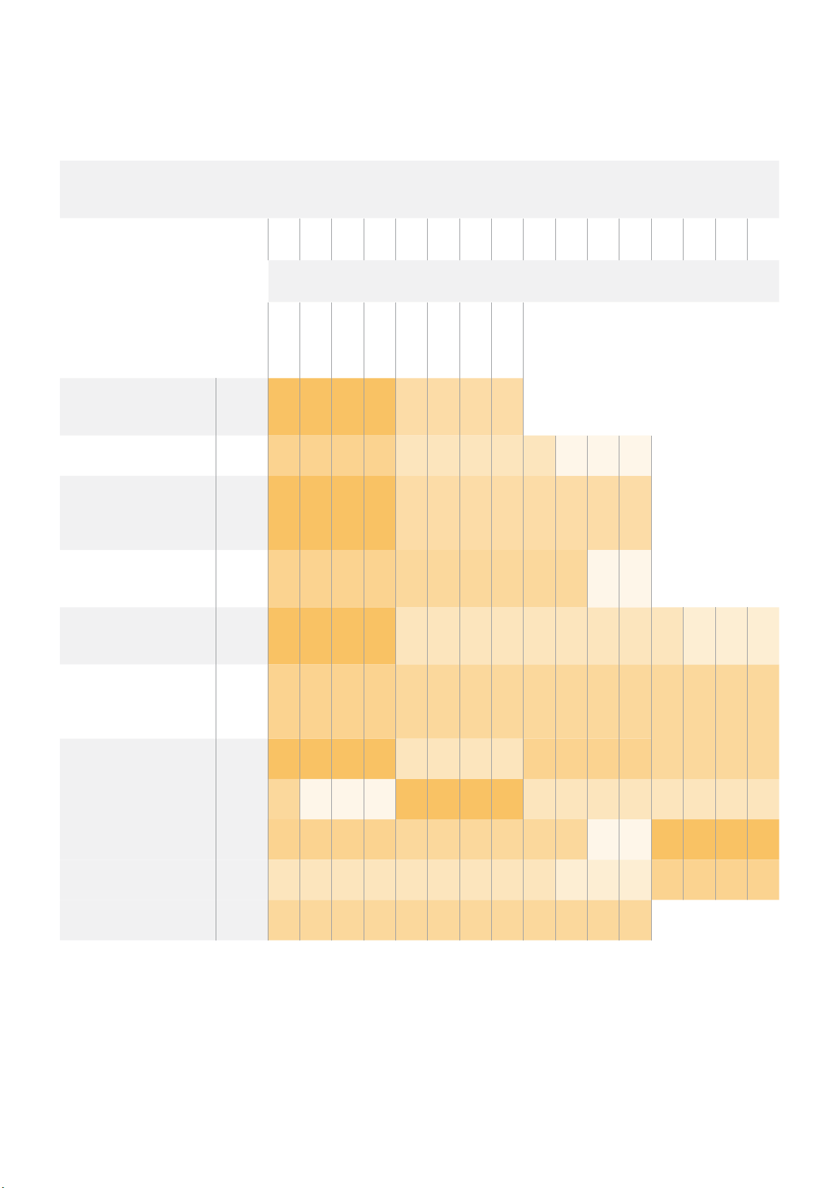
ExampleProtocolPackets
Packet
Operation
Length Byte
0 1 2 3 4 5 6 7 8 9 10 11 12 13 14 15
header command data
length
destination
trigger instantaneous
auto focus on camera 4
turn on OIS on all cameras 12 255 5 0 0 0 6 0 0 1 0 0 0
set exposure to 10 ms on
camera 4 (10 ms = 10000
us = 0x00002710)
add 15% to zebra level
(15 % = 0.15 f = 0x0133 fp)
select 1080p 23.98 mode on
all cameras
subtract 0.3 from gamma
adjust for green & blue
(-0.3 ~= 0xfd9a fp)
8 4 4 0 0 0 1 0 0
12 4 8 0 0 1 5 3 0 0x10 0x27 0x00 0x00
12 4 6 0 0 4 2 128 1 0x33 0x01 0 0
16 255 9 0 0 1 0 1 0 24 1 3 0 0 0 0 0
16 4 12 0 0 8 1 128 1 0 0 0x9a 0xfd 0x9a 0xfd 0 0
command
category
reserved
type
parameter
operation
all operations combined 76 4 4 0 0 0 1 0 0 255 5 0 0 0 6 0 0
1 0 0 0 4 8 0 0 1 5 3 0 0x10 0x27 0x00 0x00
4 6 0 0 4 2 128 1 0x33 0x01 0 0 255 9 0 0
1 0 1 0 24 1 3 0 0 0 0 0 4 12 0 0
8 1 128 1 0 0 0x9a 0xfd 0x9a 0xfd 0 0
StudioCameraControlProtocol
55
Page 56

DeveloperInformation
This section of the manual provides all the details you will need if you want to write custom
libraries and develop your own hardware for your Blackmagic 3G-SDI Shield for Arduino.
2
PhysicalEncoding
The shield operates at the following I2C speeds:
1. Standard mode (100 kbit/s)
2. Full speed (400 kbit/s)
The default 7-bit shield I
Shield Pin | Function
--------------------- |---------------------------- A4 | Serial Data (SDA)
A5 | Serial Clock (SCL)
2
C Protocol (Writes):**
**I
(START W) [REG ADDR L] [REG ADDR H] [VAL] [VAL] [VAL] ... (STOP)
2
C Protocol (Reads):**
**I
(START W) [REG ADDR L] [REG ADDR H] ... (STOP) (START R) [VAL] [VAL] [VAL] ... (STOP)
The maximum payload (shown as **VAL** in the examples above) read/write length (following
the internal register address) in a single transaction is 255 bytes.
-
I
C
2
C slave address is 0x6E.
PhysicalEncoding
The shield operates with a UART baud rate of 115200, 8-N-1 format.
Shield Pin | Function
--------------------- |---------------------------- IO1 | Serial Transmit (TX)
IO0 | Serial Receive (RX)
**UART Protocol (Writes):**
[0xDC] [0x42] [REG ADDR L] [REG ADDR H] [‘W’] [LENGTH] [0x00] [VAL] [VAL] [VAL] ...
**UART Protocol (Reads):**
[0xDC] [0x42] [REG ADDR L] [REG ADDR H] [‘R’] [LENGTH] [0x00] [VAL] [VAL] [VAL] ...
The maximum payload (shown as **VAL** in the examples above) read/write length (specified in
the **LENGTH** field) in a single transaction is 255 bytes.
Register Address Map
-
UART
DeveloperInformation
56
Page 57

The shield has the following user address register map:
Address | Name | R/W | Register Description
--------------------- |----------- |----- |-------------------------------
0x0000 - 0x0003 | IDENTITY | R | Hardware Identifier
0x0004 - 0x0005 | HWVERSION | R | Hardware Version
0x0006 - 0x0007 | FWVERSION | R | Firmware Version
| | |
0x1000 | CONTROL | R/W | System Control
| | |
0x2000 | OCARM | R/W | SDI Control Override Arm
0x2001 | OCLENGTH | R/W | SDI Control Override Length
0x2100 - 0x21FE | OCDATA | R/W | SDI Control Override Data
| | |
0x3000 | ICARM | R/W | SDI Control Incoming Arm
0x3001 | ICLENGTH | R | SDI Control Incoming Length
0x3100 - 0x31FE | ICDATA | R | SDI Control Incoming Data
| | |
0x4000 | OTARM | R/W | SDI Tally Override Arm
0x4001 | OTLENGTH | R/W | SDI Tally Override Length
0x4100 - 0x41FE | OTDATA | R/W | SDI Tally Override Data
| | |
0x5000 | ITARM | R/W | SDI Tally Incoming Arm
0x5001 | ITLENGTH | R | SDI Tally Incoming Length
0x5100 - 0x51FE | ITDATA | R | SDI Tally Incoming Data
All multi-byte numerical fields are stored little-endian. Unused addresses are reserved and read
back as zero.
Register: IDENTITY (Board Identifier)
[ IDENTITY ]
31 0
**Identity:** ASCII string ‘SDIC’ (i.e. `0x43494453`) in hexadecimal.
Register: HWVERSION (Hardware Version)
[ VERSION MAJOR ] [ VERSION MINOR ]
15 8 7 0
**Version Major:** Hardware revision, major component.
**Version Minor:** Hardware revision, minor component.
Register: FWVERSION (Firmware Version)
[ VERSION MAJOR ] [ VERSION MINOR ]
15 8 7 0
**Version Major:** Firmware revision, major component.
**Version Minor:** Firmware revision, minor component.
Register: CONTROL (System Control)
[ RESERVED ] [ OVERRIDE OUTPUT ] [ RESET TALLY ] [ OVERRIDE TALLY ] [
OVERIDE CONTROL ]
7 4 3 2 1 0
DeveloperInformation
57
Page 58

**Reserved:** Always zero.
**Override Output:** When 1, the input SDI signal (if present) is discarded and the
shield generates its own SDI signal on the SDI output
connector. When 0, the input signal is passed through to the
output if present, or the shield generates its own SDI
signal if not.
**Reset Tally:** When 1, the last received incoming tally data is immediately copied
over to the override tally data register. Automatically cleared
by hardware.
**Override Tally:** When 1, tally data is overridden with the user supplied data.
When 0, input tally data is passed through to the output
unmodified.
**Override Control:** When 1, control data is overridden with the user supplied
data. When 0, input control data is passed through to the
output unmodified.
Register: OCARM (Output Control Arm)
[ RESERVED ] [ ARM ]
7 1 0
**Reserved:** Always zero.
**Arm:** When 1, the outgoing control is data armed and will be sent in the
next video frame. Automatically cleared once the control has
been sent.
Register: OCLENGTH (Output Control Length)
[ LENGTH ]
7 0
**Length:** Length in bytes of the data to send in OCDATA.
Register: OCDATA (Output Control Payload Data)
[ CONTROL DATA ]
255*8-1 0
**Control Data:** Control data that should be embedded into a future video frame.
Register: ICARM (Incoming Control Arm)
[ RESERVED ] [ ARM ]
7 1 0
**Reserved:** Always zero.
**Arm:** When 1, incoming control data is armed and will be received in the
next video frame. Automatically cleared once a control packet has
been read.
Register: ICLENGTH (Incoming Control Length)
[ LENGTH ]
7 0
**Length:** Length in bytes of the data in _ICDATA_. Automatically set when a
new packet has been cached.
DeveloperInformation
58
Page 59

Register: ICDATA (Incoming Control Payload Data)
[ CONTROL DATA ]
255*8-1 0
**Control Data:** Last control data extracted from a video frame since _ICARM.ARM_
was reset.
Register: OTARM (Output Tally Arm)
[ RESERVED ] [ ARM ]
7 1 0
**Reserved:** Always zero.
**Arm:** When 1, the outgoing tally data is armed and will be continuously from
the next video frame until new data is set. Automatically cleared once
the tally has been sent in at least one frame.
Register: OTLENGTH (Output Tally Length)
[ LENGTH ]
7 0
**Length:** Length in bytes of the data to send in OTDATA.
Register: OTDATA (Output Tally Data)
[ TA LLY DATA ]
255*8-1 0
**Tally Data:** Tally data that should be embedded into a future video frame (one
byte per camera). Bit zero indicates a Program tally, while bit one
indicates a Preview tally.
Register: ITARM (Input Tally Arm)
[ RESERVED ] [ ARM ]
7 1 0
**Reserved:** Always zero.
**Arm:** When 1, tally data armed and will be received in the next video frame.
Automatically cleared once the tally has been read.
Register: ITLENGTH (Input Tally Length)
[ LENGTH ]
7 0
**Length:** Length in bytes of the data in _ITDATA_. Automatically set when a
new packet has been cached.
Register: ITDATA (Input Tally Data)
[ TA LLY DATA ]
255*8-1 0
**Tally Data:** Last tally data extracted from a video frame since _ITARM.ARM_ was
reset (one byte per camera). Bit zero indicates a Program tally, while
bit one indicates a Preview tally.
DeveloperInformation
59
Page 60

ヘ ルプ
ヘ ルプラ イン
Blackmagic3G-SDIShieldforArduinoは、ユーザーの要望に基づいて単独で開発できるよう設計された
デベロッパー ツ ールで す。
シールドに関する最新の 情 報が欲しい方は、BlackmagicDesignオンラインサポートページで、最新サポー
ト情 報 を確 認 で きま す。
BlackmagicDesign オンラインサポートページ
最 新 のマニュアル、ソフトウェア、サ ポートノートは、
サポートセンターで確 認で きます。
Arduino開 発 フォー ラム
プログラミングに関する質問がある方は、インターネットの
Arduino
存 在します。また 、エン ジニアを雇ってソリューションを 作成してもらうこともで きるでしょう。
デベロッパーのコミュニティは幅広く、ソフトウェアに関する質問ができる良 質 なフォーラムが 数多く
BlackmagicDesignフォーラム
弊 社 ウェブ サイト の
有益なリソースです。経験豊富なユーザーやBlackmagicDesignス タ ッ フ に よ っ て 、す で に 多 く の 問 題 の 解 決
策が公開されていますので、このフォーラムを参 考にすることで、現在の問題をすばやく解決で きることが あり
ま す 。ぜ ひ ご 利 用 く だ さ い 。
スで きま す。
BlackmagicDesign
Blackmagic
フォーラムには 、
www.blackmagicdesign.com/jp/supportのBlackmagic
Arduino
フ ォ ー ラ ム は 、様 々 な 情 報 や ク リ エ イ テ ィ ブ な ア イ デ ア を 共 有 で き る
://
http
開発フォーラムで助けを得られます。
forum.blackmagicdesign.com
か らアク セ
現在インストールされているソフトウェアのバージョンを 確認
コンピュー ター にインストールされているBlackmagic3G
ジ ョ ン を 確 認 す る に は 、「
MacOSX
を開きます。アプリケーションメニューから「
選択し、バージョンを確認します。
Windows7
ます。ヘルプメニュー を クリックして「
バー ジョンを 確 認 します。
Windows8
Blackmagic3G-SDIShieldforArduinoSetup
BlackmagicShieldforArduinoSetup
AboutBlackmagic3G-SDIShieldforArduinoSetup」ウ ィ ン ド ウ を 開 き ま す 。
で は 、ア プ リ ケ ー シ ョ ン フ ォ ル ダ ー か ら「
で は 、ス タ ー ト メ ニ ュ ー か ら「
AboutBlackmagicShieldforArduinoSetup
で は 、ス タ ー ト ペ ー ジ の「
Blackmagic3G-SDIShieldforArduinoSetup
-
SDIShieldforArduinoSetupソフトウェ アのバー
Blackmagic3G-SDIShieldforArduinoSetup
AboutBlackmagicShieldforArduinoSetup
Blackmagic3G-SDIShieldforArduinoSetup
を開きます。ヘルプメニューをクリックして「
」を選択し、バージョンを確認します。
」
」を
」を 開 き
」を 選 択 し 、
」タ イ ル か ら
About
最新のソフトウェアアップデートを入手する
コンピュー ター にインストールされ たBlackmagic 3G
ジョンを確 認した後、Blackmagicサ ポ ー ト セ ン タ ー( www
で 最 新のソフトウェア アップ デ ートを確 認してください 。常に最 新 のソフトウェアを使 用 することを推 奨しま す
が、重要なプ ロジェクトの実 行 中は 、ソフトウェアのアップ デ ートは 行わない方がよいでしょう。
-
SDIShieldfor Arduino Setupソフトウェア のバー
.
blackmagicdesign.com/jp/support)
ヘルプ
60
Page 61

保証
ヶ月限 定 保 証
12
BlackmagicDesignは、お買い上げの日から12ヶ月間 、Blackmagic3G-SDIShield for Arduinoの部品
および仕上がりについて瑕疵がないことを保証します。この保証期間内に製品に瑕疵が見つかった場
合、BlackmagicDesignは弊社の裁量において部品代および人件費無料で該当製品の修理、あるいは製品の
交 換 の いず れ かで 対 応 い たしま す。
この保証に基づいたサービスを受ける際、お客 様は必ず保証期限終了前に
知し、適応する保証サービスの手続きを行ってください。お客 様の責任において不良品を梱 包し、
Design
が指 定 するサ ポートセンター へ配 送 料 前払で送 付 いただきま すようお願い 致します。理由の如何を問 わ
BlackmagicDesign
に瑕疵を通
Blackmagic
ず、Blackmagic Designへの製品返送のための配送料、保険、関税、税金、その他すべての費用はお客様の
自己負 担と な りま す。
不適切な使用、または不十分なメンテナンスや取扱いによる不具合、故障 、損傷に対しては、この保 証は適用さ
れません。
BlackmagicDesign
はこの保証で、以下に関してサービス提供 義務を負わないものとします。a)
製品のインストールや修理、サービスを行うBlackmagicDesign販 売 代 理 人 以 外 の 者 に よ って 生じ た 損 傷 の
修理、
b)不適切な使用や互換性のない機器への接続によって生じた損傷の修理、c)BlackmagicDesignの
部品や供給品ではない物を使用して生じたすべての損傷や故障の修理、d)改 造 や 他 製 品 と の 統 合 に よ り 時 間
増加や製品の機能低下が生じた場合のサービス。この保証は
BlackmagicDesign
が 保 証 す る も の で 、明 示
または黙示を問わず他の保証すべてに代 わるものです。BlackmagicDesignと そ の 販 売 社 は 、商 品 性 と 特 定
目的に対する適合性のあらゆる黙示保証を拒否します。
の責任が、特別に、間接的、偶発的、または結果的に生じる損害に対して、
BlackmagicDesign
BlackmagicDesign
の不良品の 修 理あるいは交 換
あるいは 販 売
社がそのような損害の可能性についての事前通知を得ているか否かに関わらず、お客様に提供される完全唯一
の 救 済 手 段となります。BlackmagicDesignはお客 様による機 器のあらゆる 不法使用に対して責任 を負いま
せん。BlackmagicDesignは本製品 の使用により生じるあらゆる損害に対して責任を負いません。使用 者は
自己の責任において本製品を使用するものとします。
©Copyright2020年BlackmagicDesign
WorkgroupVideohub
「
の登録商標です。その他の企業名ならびに製品名全てはそれぞれ関連する会社の登録商標である可能性があります。
Arduino
のロゴは 、
の 登 録 商 標 で す。
Arduino
Videohub
」 、「
の 登 録 商 標 で す。
著作権所有、無断複写・転載を禁じます。「
Intensity
」 、「
Thunderbolt
Leadingthecreativevideorevolution
」 、「
Thunderbolt
および
BlackmagicDesign
の ロ ゴ は 、米 国 ま た は そ の 他 諸 国 の
DeckLink
」 、「
」は 、米 国 な ら び に そ の 他 諸 国 で
HDLink
」 、「
Arduino
IntelCorporation
」、
および
保証
61
Page 62

Manuel d’installation et d’utilisation
Manuel de la
Blackmagic 3G-SDI
Shield for Arduino
Février 2020
Français
62
Page 63

Cher client, chère cliente,
Nous vous remercions d’avoir fait l’acquisition d’une carte Blackmagic 3G-SDI Shield for Arduino.
Nous nous intéressons aux nouvelles technologies et souhaitons développer des façons innovantes
d’utiliser nos produits SDI. Grâce à la 3G-SDI Shield for Arduino, vous pouvez désormais intégrer
une carte Arduino à votre workflow SDI et ainsi ajouter des options de contrôle à votre équipement
Blackmagic Design.
Par exemple, les mélangeurs ATEM peuvent contrôler la Blackmagic URSA Mini et les Blackmagic
Studio Cameras via des paquets de données intégrés au signal SDI. Si vous n’utilisez pas de
mélangeur ATEM, mais que vous souhaitez pouvoir contrôler vos caméras Blackmagic, vous pouvez
créer des solutions de contrôle personnalisées à l’aide de la 3G-SDI Shield for Arduino. Cette carte
vous offre une plateforme de création, qui vous permet d’envoyer le signal de retour du programme
provenant du mélangeur vers la carte, puis vers l’entrée de programme de votre caméra Blackmagic.
Il est très facile d’écrire un code pour envoyer des commandes à la caméra. De plus, toutes les
commandes prises en charge sont décrites dans ce manuel.
Vous pouvez contrôler les caméras à l’aide d’un ordinateur ou ajouter des boutons, molettes et
joysticks à votre carte. Vous disposerez ainsi de solutions de contrôle dynamiques qui permettent
de modifier des fonctionnalités telles que la mise au point, le zoom, l’ouverture, le niveau de noir,
la balance des blancs, le correcteur de couleurs intégré à la caméra et autres. Créer sa propre
solution de contrôle est utile à la production, mais aussi très amusant !
Nous sommes très heureux de pouvoir proposer cette technologie et nous avons hâte de découvrir
les solutions de contrôle SDI que vous avez conçues avec la 3G-SDI Shield for Arduino !
Ce manuel d’utilisation comprend toutes les informations dont vous avez besoin pour utiliser
la Blackmagic 3G-SDI Shield for Arduino. Consultez notre page d’assistance sur
www.blackmagicdesign.com/fr pour obtenir la dernière version du manuel et les mises à jour
du logiciel interne de la carte. Nous vous recommandons de mettre le logiciel à jour régulièrement
afin de travailler avec les fonctions les plus récentes. N’oubliez pas d’enregistrer vos coordonnées
lorsque vous téléchargerez le logiciel afin d’être informé des dernières mises à jour. Nous souhaitons
continuer à améliorer nos produits, n’hésitez donc pas à nous faire part de vos commentaires !
Grant Petty
PDG de Blackmagic Design
Page 64

Sommaire
Manuel de la Blackmagic 3G-SDI Shield
for Arduino
Mise en route 65
Fixer et souder les barrettes 65
Installation sur la carte Arduino 66
Branchement de l'alimentation 66
Connexion à du matériel SDI 67
Installation du logiciel 68
Installation du logiciel interne 68
Installation des fichiers bibliothèqueArduino 69
Blackmagic Shield for Arduino Setup 70
2
C Address 70
I
Format vidéo 71
Programmation des sketches Arduino 71
Test de la carte extension Blackmagic et installation de la bibliothèque 72
Voyants LED 73
Fixation de composants surlacarteextension 74
Communiquer avec votre Blackmagic Shield for Arduino 74
High Level Overview 74
2
C Interface 75
I
Serial Interface 75
Example Usage 75
Studio Camera Control Protocol 76
Blackmagic SDI Camera Control Protocol 77
Overview 77
Assumptions 77
Blanking Encoding 77
Message Grouping 77
Abstract Message Packet Format 77
Defined Commands 78
Example Protocol Packets 85
Informations pour les développeurs 86
Physical Encoding - I
Physical Encoding - UART 86
2
C 86
Assistance 90
Garantie 91
Page 65
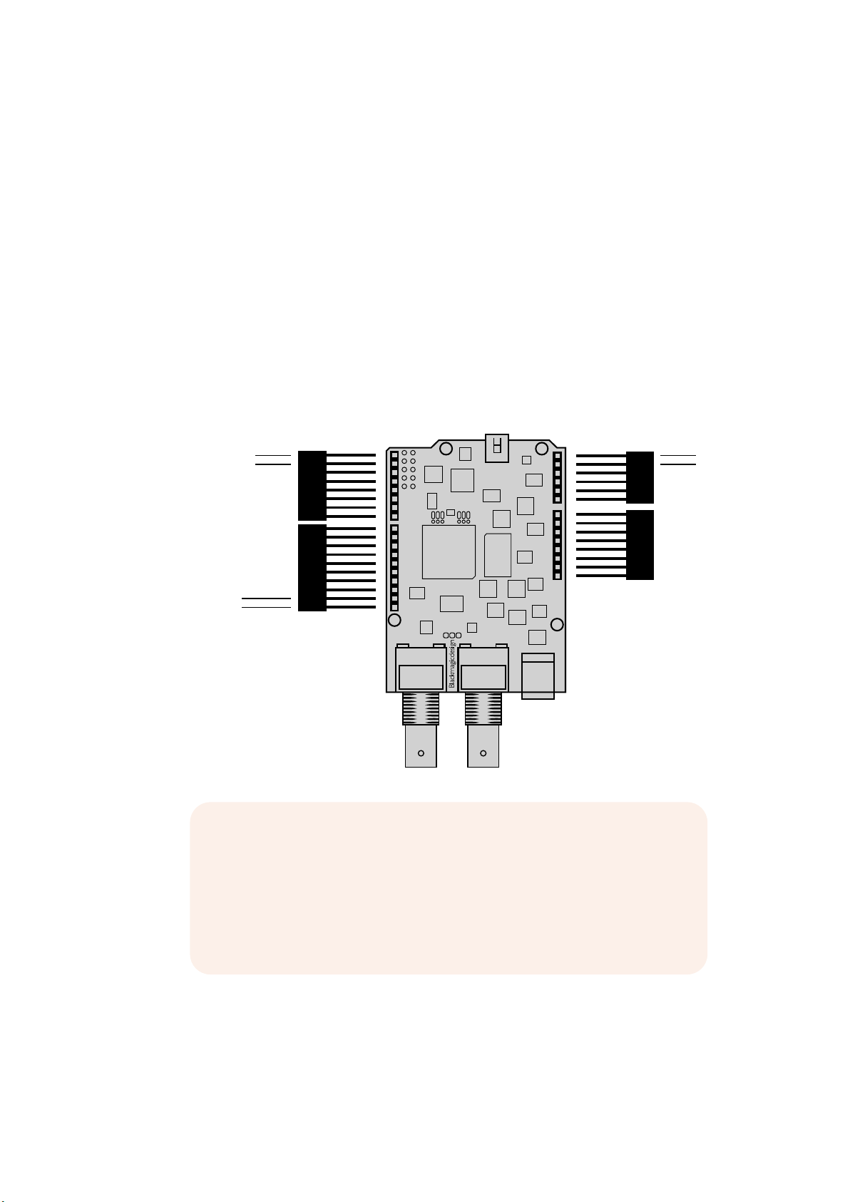
Mise en route
6 PIN
8 PIN
Fixer et souder les barrettes
La Blackmagic 3G-SDI Shield for Arduino est fournie avec 4 barrettes, dont deux barrettes mâles à
8 broches, une à 10 broches et une à 6 broches. Les barrettes sont des connecteurs qui permettent
d’installer votre carte extension sur l’Arduino. Comme elles se superposent, vous pouvez installer
d’autres cartes les unes sur les autres ainsi que des composants, notamment des boutons de
contrôle, des molettes et des joysticks. Ces barrettes sont conçues pour être installées sur les
cartes Arduino R3, telles que l’Arduino UNO.
Pour fixer les barrettes à votre carte extension :
1 Insérez les broches de chaque barrette dans les trous correspondants situés de part et
d’autre de la Blackmagic 3G-SDI Shield. L’illustration ci-dessous vous indique la disposition
des barrettes.
0 - Serial RX
1 - Serial TX
(I2C) SDA
(I2C) SCL
REMARQUE Lors de la connexion à la carte extension, la communication
est établie via le protocole I2C ou le protocole série. Nous recommandons
de choisir I2C afin de pouvoir utiliser le moniteur série et les autres broches.
Sélectionnez le mode de communication lorsque vous définissez l’objet
BMDSDIControl dans le sketch. Pour plus d’informations, consultez la
section « Communication avec la Blackmagic 3G-SDI Shield for Arduino »
de ce manuel.
A5 (I2C) SCL
A4 (I2C) SDA
2 Soudez la base de chaque broche à la face inférieure de votre carte extension. Veillez à
ce que chaque broche soit solidement raccordée au trou correspondant, sans entrer en
contact avec la soudure des autres broches.
65Mise en route
Page 66
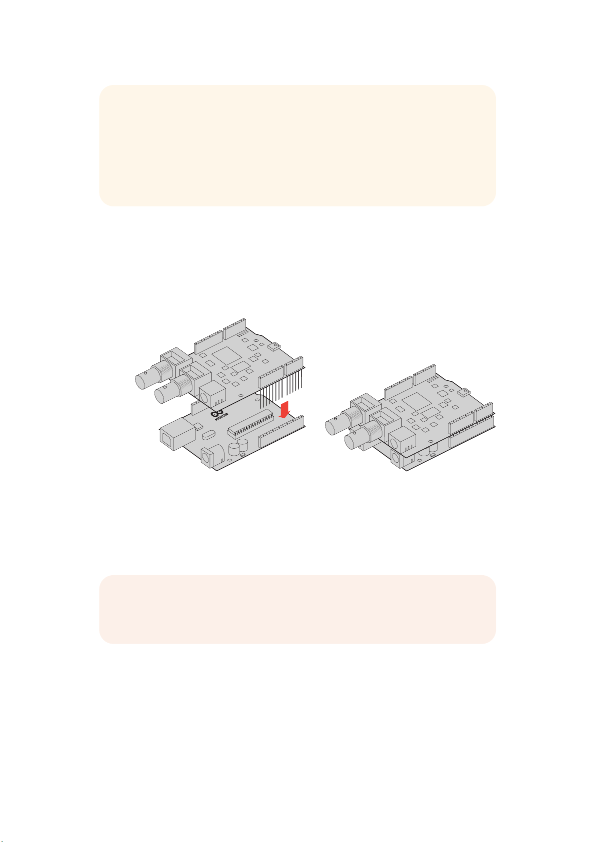
CONSEIL Afin que toutes les broches de la carte extension soient bien alignées
avec les trous de la barrette de l'Arduino, nous vous recommandons, dans un
premier temps, de ne souder qu'une broche sur chaque barrette. Placez ensuite la
carte extension sur l'Arduino pour vérifier l'alignement des broches. Si certaines
barrettes ont besoin d'être ajustées, vous pouvez réchauffer la soudure et ainsi
améliorer leur alignement. C'est bien plus facile que de souder toutes les broches
et d'essayer de les ajuster par la suite.
Installation sur la carte Arduino
Une fois les barrettes soudées sur votre carte extension, vous pouvez l'installer sur la carte Arduino.
Saisissez les deux côtés de la carte extension et alignez les broches avec les barrettes de l'Arduino.
Poussez délicatement les broches dans les trous des barrettes. Veillez à ne pas plier les broches
lors de l'installation.
Une fois les broches enfoncées, la carte extension Blackmagic et la carte
Arduino doivent être fermement connectées.
Branchement de l'alimentation
Pour alimenter votre Blackmagic 3G-SDI Shield for Arduino, il suffit de brancher un adaptateur
12V à l’entrée d’alimentation 12V de la carte extension Blackmagic.
REMARQUE L'alimentation de la carte Arduino n'est pas suffisante pour les deux
cartes. En revanche, si vous alimentez la carte Blackmagic, la carte Arduino sera
également alimentée. Veillez donc à n'alimenter que la carte Blackmagic.
66Mise en route
Page 67
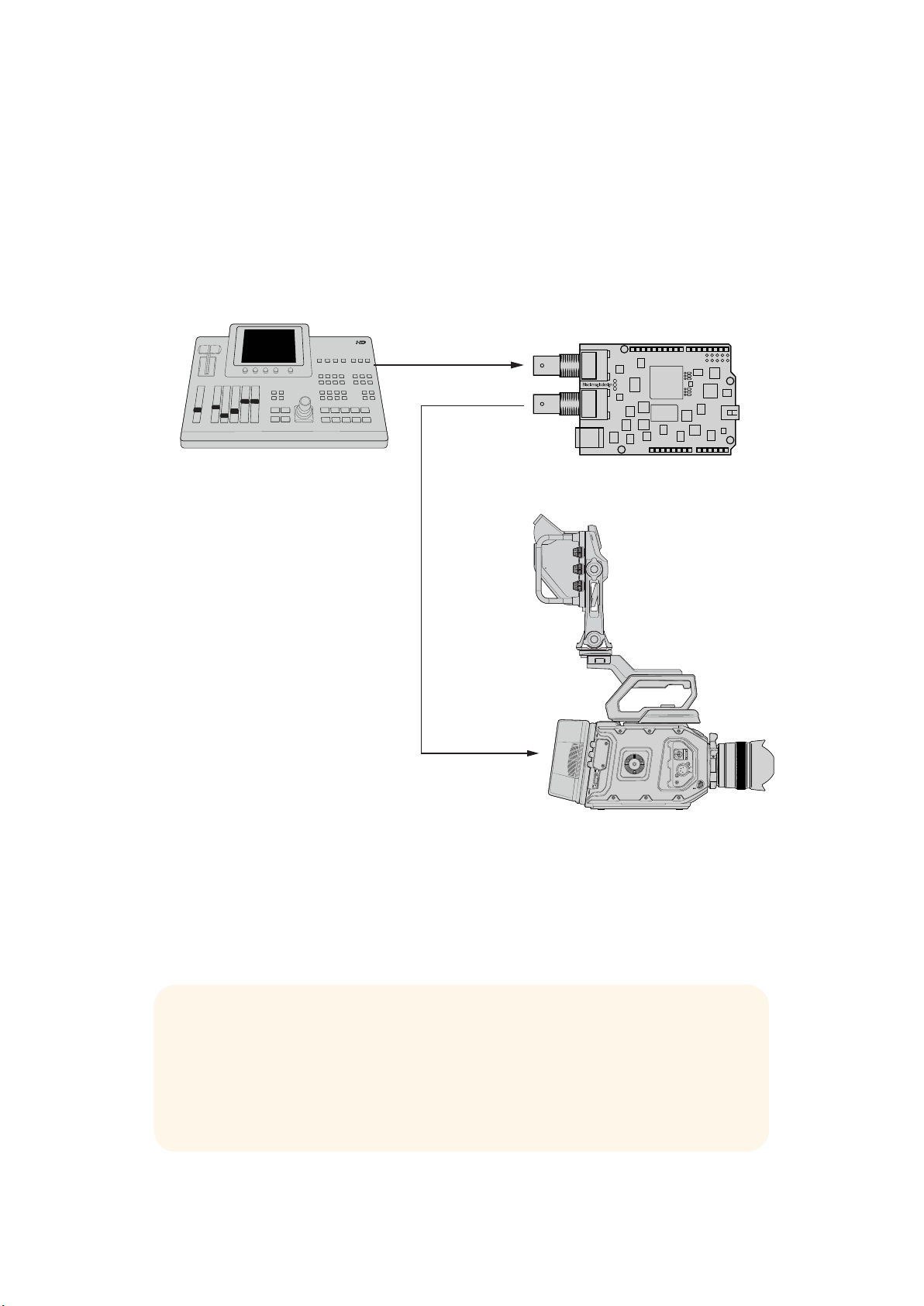
Connexion à du matériel SDI
Blackmagic URSA Mini
Une fois la carte alimentée, vous pouvez la connecter à du matériel SDI. Par exemple, un mélangeur
et une Blackmagic URSA Mini :
1 Branchez la sortie programme du mélangeur à l’entrée SDI de la Blackmagic 3G-SDI Shield.
2 Branchez la sortie SDI de la Blackmagic 3G-SDI Shield à l’entrée programme SDI (PMG) de
la Blackmagic URSA Mini.
Vous trouverez ci-dessous un schéma de connexion.
Entrée SDI
Sortie SDI
Mélangeur
Entrée SDI PGM
Blackmagic 3G-SDI Arduino Shield
C'est tout ce que vous devez savoir pour démarrer !
Maintenant que votre carte est montée sur l'Arduino, qu'elle est alimentée et connectée à du
matériel SDI, vous pouvez installer le logiciel interne et les fichiers bibliothèque.
Consultez le reste du manuel pour obtenir plus d'informations sur l'installation du logiciel interne de
la carte extension et sur l'installation des fichiers bibliothèque afin que la carte extension puisse
communiquer avec l'Arduino.
CONSEIL Vous pouvez également utiliser la Blackmagic 3G-SDI Shield for Arduino
pour contrôler d’autres produits Blackmagic Design, tels que le Blackmagic
MultiView 16. Par exemple, lorsque la carte est connectée à l’entrée 16 de l’appareil,
une bordure tally s’affiche sur le multivue. Lorsque vous utilisez des caméras
Blackmagic URSA Mini, veillez à activer la grille afin d’afficher le tally sur le viseur de
la caméra. Pour plus d’informations, consultez le manuel des caméras Blackmagic.
67Mise en route
Page 68

Installation du logiciel
REMARQUE Avant d’installer l’utilitaire Blackmagic Shield for Arduino Setup,
téléchargez la dernière version du logiciel Arduino IDE depuis le site
www.arduino.cc et installez-le sur votre ordinateur.
Après avoir installé le logiciel Arduino, vous pouvez installer le logiciel internet
de votre Blackmagic 3G-SDI Shield.
Installation du logiciel interne
Le Blackmagic Shield for Arduino Setup permet de mettre à jour le logiciel interne de la carte
extension. Le logiciel interne communique avec l’Arduino et contrôle la carte à l’aide des fichiers
bibliothèque Arduino. Ces fichiers bibliothèque sont installés avec le logiciel d’installation. Il suffit
donc de copier le dossier contenant les fichiers et de le coller dans le dossier application de
l’Arduino. Pour plus d’informations concernant l’installation des fichiers bibliothèque, consultez
la section suivante du manuel.
Nous vous recommandons de télécharger la dernière version du logiciel Blackmagic Shield
for Arduino et de mettre la carte à jour afin de bénéficier des nouvelles fonctionnalités et
améliorations. Vous pouvez télécharger la dernière version de ce manuel sur la page d’assistance
de Blackmagic Design www.blackmagicdesign.com/fr/support.
Pour installer le logiciel interne avec Mac OS X :
1 Téléchargez et dézippez le logiciel Blackmagic Shield for Arduino.
2 Ouvrez l’image disque et lancez le programme d’installation Blackmagic Shield for Arduino.
Suivez les instructions affichées à l’écran.
3 Après avoir installé la dernière version du programme d’installation Blackmagic Shield for
Arduino, alimentez la carte extension Blackmagic et connectez-la à votre ordinateur à l’aide
d’un câble USB.
4 Lancez le programme d’installation et suivez les informations affichées à l’écran pour mettre
à jour le logiciel interne de la carte extension. Si aucune mise à jour n’apparaît, le logiciel
interne est à jour.
Pour installer le logiciel interne avec Windows :
1 Téléchargez et dézippez le logiciel Blackmagic Shield for Arduino.
2 Le dossier Blackmagic Shield for Arduino s’affiche, il contient le manuel et le programme
d’installation Blackmagic Shield for Arduino. Double-cliquez sur le programme d’installation
et suivez les instructions à l’écran pour terminer l’installation.
3 Après avoir installé la dernière version du programme d’installation Blackmagic Shield for
Arduino, alimentez la carte extension Blackmagic et connectez-la à votre ordinateur à l’aide
d’un câble USB.
4 Lancez le programme d’installation et suivez les informations affichées à l’écran pour mettre
à jour le logiciel interne de la carte extension. Si aucune mise à jour n’apparaît, le logiciel
interne est à jour.
68Installation du logiciel
Page 69

Installation des fichiers
bibliothèqueArduino
Les programmes conçus pour contrôler l’Arduino sont appelés croquis ou sketches. La Blackmagic
3G-SDI Shield for Arduino utilise des fichiers bibliothèque Arduino pour faciliter l’écriture des
sketches. Après avoir installé le logiciel de la carte extension, les fichiers bibliothèque sont installés
dans un dossier intitulé Library. Il suffit à présent de copier le dossier contenant ces fichiers et de
le coller dans le dossier bibliothèque de l’Arduino.
REMARQUE Le logiciel IDE Arduino doit être fermé lorsque vous installez les
bibliothèques.
Pour installer les fichiers bibliothèque sur Mac OS X :
1 Ouvrez Blackmagic Shield for Arduino dans le dossier Applications.
2 Ouvrez le dossier Library et faites un clic droit/copiez le dossier intitulé : BMDSDIControl.
3 Dans le dossier Documents de votre ordinateur, ouvrez le dossier Arduino.
4 Vous verrez un sous-dossier intitulé Libraries. Collez le dossier BMDSDIControl dans
le dossier Libraries.
Pour installer les fichiers bibliothèque sur Windows :
1 Ouvrez Programmes/ Blackmagic Shield for Arduino.
2 Vous verrez un sous-dossier intitulé Library. Ouvrez ce dossier et faites un clic droit/copiez
le dossier intitulé : BMDSDIControl.
3 Dans le dossier Documents de votre ordinateur, ouvrez le dossier Arduino.
4 Vous verrez un sous-dossier intitulé Libraries. Collez le dossier BMDSDIControl dans le
dossier Libraries.
C'est tout ce que vous devez faire pour installer les fichiers bibliothèque Blackmagic Design sur
votre ordinateur. Lorsque vous utilisez le logiciel Arduino, vous disposerez désormais d'exemples
de sketches Blackmagic Design.
Dans le menu déroulant Fichier du logiciel Arduino, sélectionnez Exemples. Sélectionnez
BMDSDIControl pour afficher la liste d'exemples de sketches que vous pouvez utiliser.
Une fois les fichiers bibliothèque stockés dans le dossier approprié, la carte extension peut les
utiliser pour communiquer avec l'Arduino. Il ne reste plus qu'à programmer le logiciel IDE Arduino.
Pour plus d'informations à ce sujet, consultez la section « Programmation des sketches Arduino »
de ce manuel.
REMARQUE Si une mise à jour de la bibliothèque comportant des exemples est
disponible, vous devrez supprimer l'ancien dossier BMDSDIControl et le remplacer
par le nouveau dossier en suivant les étapes décrites ci-dessus.
69Installation des fichiers bibliothèqueArduino
Page 70

Blackmagic Shield for Arduino Setup
Le logiciel Blackmagic Shield for Arduino Setup vous permet de changer les paramètres
de la carte extension, notamment l’adresse I
Grâce au logiciel Blackmagic Shield for Arduino Setup installé sur votre ordinateur, vous pouvez
changer les paramètres de la carte extension : I
afin que l’Arduino puisse communiquer avec elle ; Video Format, permet de régler
le format de sortie de la carte extension.
2
C et le format de sortie vidéo.
2
C address, permet de reconnaître la carte extension
I2C Address
Exceptionnellement, il se peut qu'une autre carte extension montée sur la carte extension
Blackmagic partage l’adresse I
vous pouvez changer l'adresse par défaut de la carte extension.
2
C par défaut, ce qui peut créer un conflit. Si cela ce produit,
70Blackmagic Shield for Arduino Setup
Page 71

L'adresse par défaut pour la carte extension est 0x6E, cependant, vous pouvez choisir des adresses
comprises entre 0x08 et 0x77.
Changer l'adresse de la carte extension :
1 Lancez le Blackmagic Shield for Arduino Setup et cliquez sur l’icône de paramétrage.
2 Dans le paramètre Set address to:, saisissez l'adresse que vous souhaitez utiliser.
3 Cliquez sur Save.
Format vidéo
Si aucun signal d’entrée n'est connecté, le format de sortie par défaut est choisi par le logiciel
d'installation. Lorsqu'un signal d’entrée est connecté, la sortie est configurée au même format que
celui de l'entrée. Si l'entrée est déconnectée, le format de sortie par défaut sera choisi par le logiciel.
Vous pouvez changer le format vidéo dans le menu déroulant Default output format.
Les formats vidéo suivants sont disponibles :
720p50
720p59.94
720p60
1080i50
1080i59.94
1080i60
1080p23.98
1080p24
1080p25
1080p29.97
1080p30
1080p50
1080p59.94
1080p60
Programmation des sketches Arduino
Les programmes Arduino, également appelés croquis ou sketches, sont très faciles à écrire.
Cessketches sont programmés en langage C. Lorsque vous programmez les sketches avec les
commandes du Studio Camera Control Protocol, la carte extension intègre ces commandes à la
sortie SDI qui permet de contrôler la Blackmagic URSA Mini ou les Blackmagic Studio Camera.
Toutes les commandes prises en charge sont incluses dans la section « Studio Camera Control
Protocol » de ce manuel. Vous pouvez donc les utiliser pour vos sketches.
71Programmation des sketches Arduino
Page 72
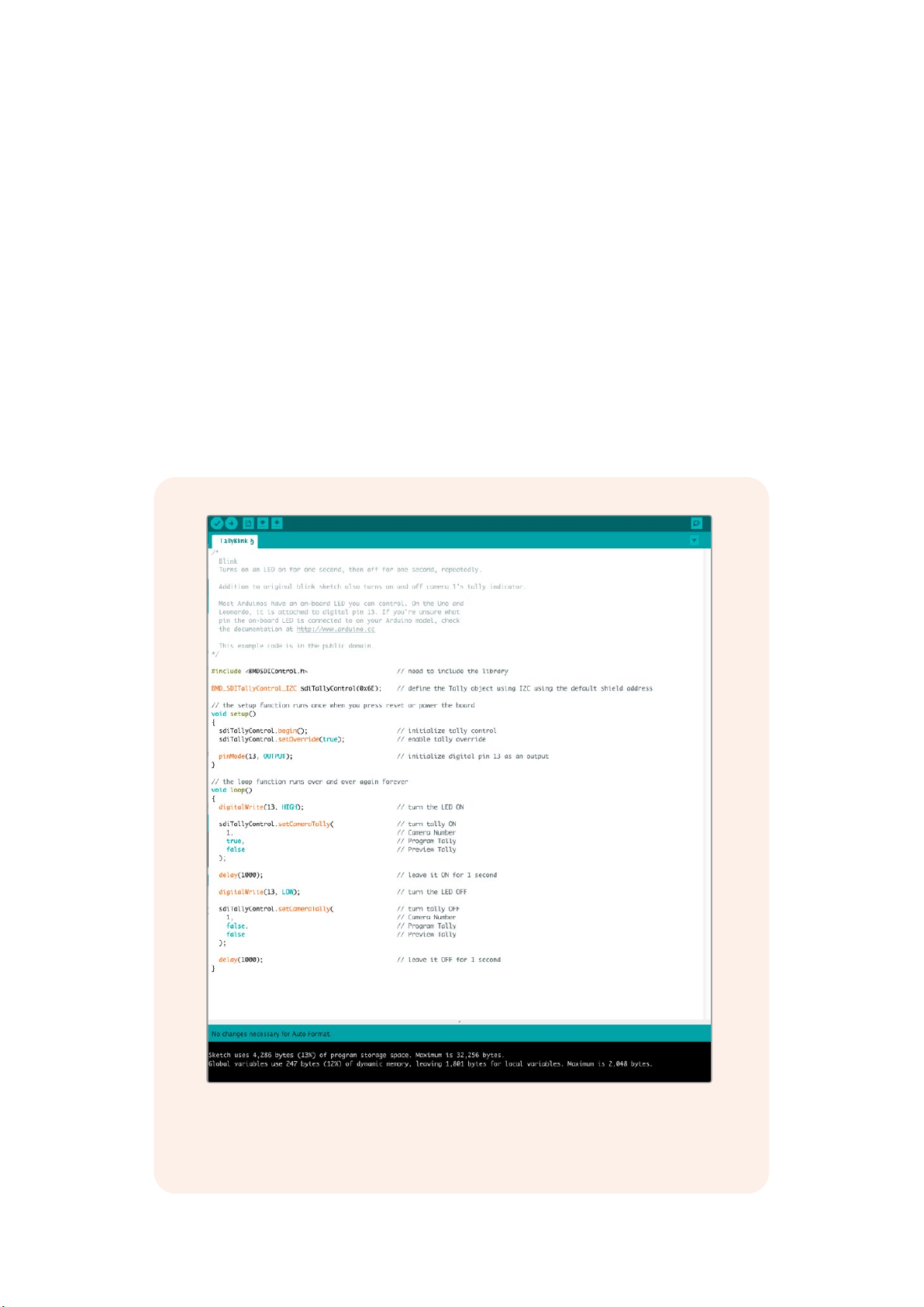
Test de la carte extension Blackmagic et installation de la bibliothèque
Une fois la carte extension connectée comme indiqué dans la section « Mise en route », et le logiciel
et les fichiers bibliothèque installés, veuillez vérifier que la carte extension communique
correctement avec la carte Arduino.
Pour vérifier cela, ouvrez et exécutez l’exemple de sketch TallyBlink présenté ci-dessous.
Suivez les étapes suivantes :
1 Lancez le logiciel IDE Arduino.
2 Allez dans le menu Outils et sélectionnez le type de carte Arduino et le port.
3 Dans le menu Fichier, sélectionnez Exemples/BMDSDIControl et choisissez le sketch
appelé TallyBlink.
4 Chargez le sketch sur la carte.
L’exemple de sketch Tally Blink est simple à réaliser pour tester votre Blackmagic 3G-SDI
Shield for Arduino. Les données brutes peuvent être envoyées à la carte via I2C à l’aide des
commandes du Studio Camera Protocol. Nous avons également inclus des bibliothèques
personnalisées pour rendre la programmation de sketches encore plus facile.
72Test de la carte extension Blackmagic et installation de la bibliothèque
Page 73
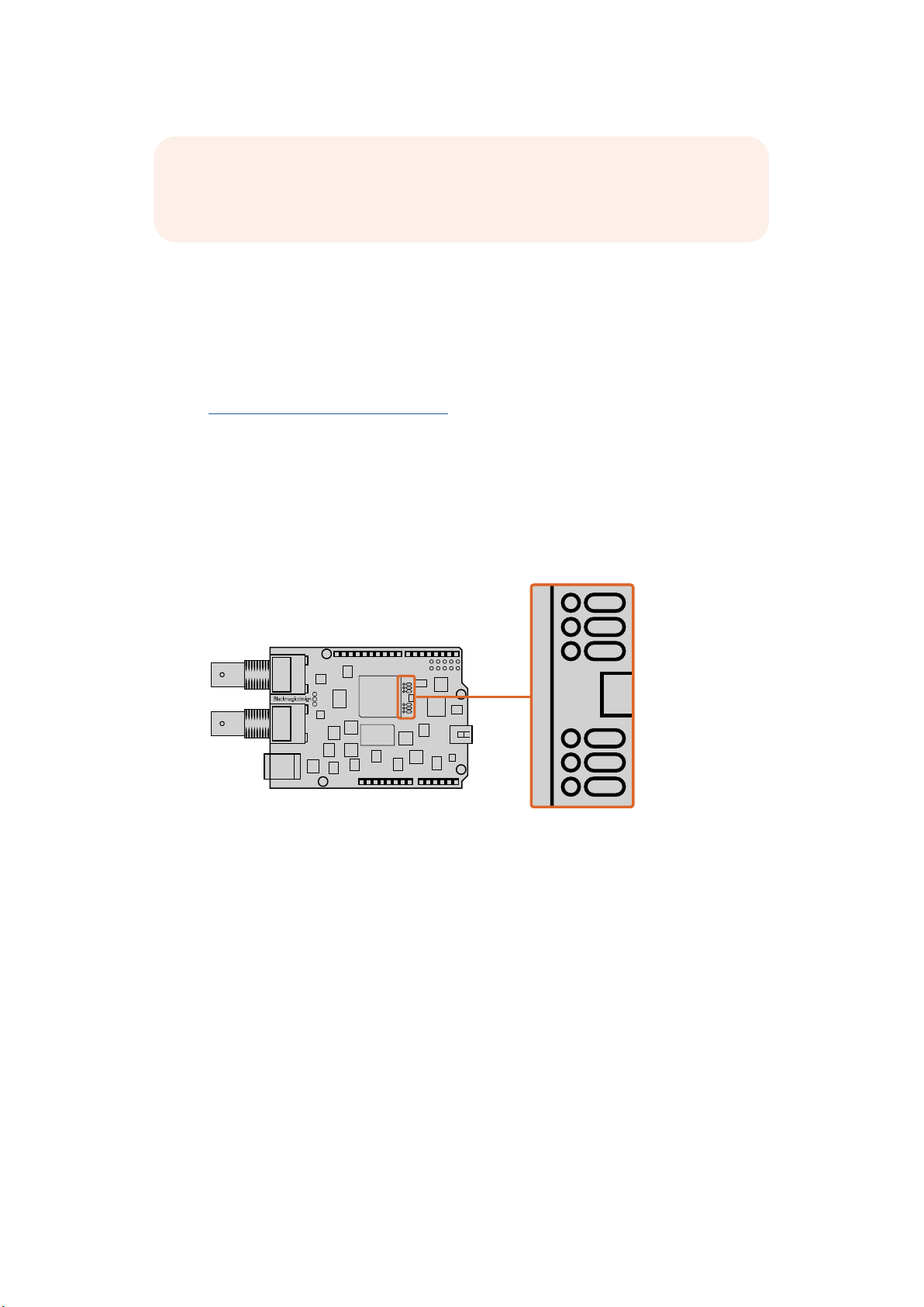
REMARQUE Vérifiez que le numéro du tally de la caméra est réglé sur 1. Aussi,
10 PIN
8 PIN
8 PIN
veillez à activer la grille afin d’afficher le tally sur le viseur de la caméra. Pour plus
d’informations, consultez le manuel des caméras Blackmagic.
Vous devriez voir le voyant tally de la Blackmagic Studio Camera clignoter une fois par seconde.
Sile voyant tally clignote, cela signifie que la carte extension Blackmagic communique avec la carte
Arduino et que tout fonctionne correctement.
Si le voyant ne clignote pas, vérifiez que le numéro du tally de la caméra est bien réglé sur 1 et que
la grille de la caméra est activée.
Si vous avez besoin d'aide, consultez la page d'assistance technique Blackmagic Design à l’adresse
suivante www.blackmagicdesign.com/fr/support. Veuillez lire la section d'assistance de ce manuel
pour obtenir davantage d'informations sur le fonctionnement de votre carte extension.
Voyants LED
La Blackmagic 3G-SDI Shield for Arduino comprend six voyants LED qui permettent de confirmer
les activités de la carte extension, par exemple, l’alimentation, la liaison UART ainsi que la
communication I
du tally et des commandes de la caméra est activée.
2
C et SPI. Les voyants indiquent également lorsque la prise de contrôle manuel
LED 1
LED 2
LED 3
LED 4
LED 5
LED 6
LED 1 - Système actif
S'allume lorsque l'alimentation est connectée à la carte extension.
LEC 2 - Prise de contrôle manuel de la commande activée
S'allume lorsque les commandes de la caméra sont activées sur le sketch Arduino.
LEC 3 - Prise de contrôle manuel du tally activée
S'allume lorsque les commandes du tally sont activées sur le sketch Arduino.
LED 5 - Analyseur I
S'allume lorsque la communication est détectée entre la carte extension et l'Arduino
avec le protocole I
LED 6 - Analyseur série occupé
S'allume quand la liaison UART est détectée.
Lorsque la carte extension Blackmagic s'allume, le voyant d'alimentation reste éteint
et les LED 3, 4 et 5 indiquent les activités suivantes.
LED 3 - Chargement de l’image de l’application
LED 4 - Initialisation de la mémoire EEPROM
LED 5 - Vérification de la mémoire en cours
2
C occupé
2
C.
73Test de la carte extension Blackmagic et installation de la bibliothèque
Page 74

Une fois la carte extension démarrée, le voyant d’alimentation s'allume et les autres LED reprennent
leur fonction standard.
En cas de problème au cours du démarrage, les LED qui rencontrent des problèmes ne clignotent
pas. En revanche, celles qui fonctionnent clignotent rapidement. Cela vous permet d’identifier
facilement l'origine du problème.
Fixation de composants
surlacarteextension
Si vous souhaitez créer votre propre contrôleur matériel, vous pouvez construire une nouvelle carte
extension dotée de boutons, de molettes et d’un joystick pour effectuer un contrôle plus précis.
Fixez simplement la carte extension personnalisée à la Blackmagic 3G-SDI Shield for Arduino en
l’insérant dans les trous de la barrette. Vous pouvez ajouter le nombre de contrôleurs dont vous
avez besoin. Si vous le souhaitez, vous pouvez même remplacer le circuit électronique d’une
ancienne voie de commande par votre propre Arduino.
Créez votre propre contrôleur matériel et fixer-le à la Blackmagic
3G-SDI Shield for Arduino pour un contrôle extrêmement précis.
Communiquer avec votre Blackmagic Shield for Arduino
You can communicate with your Blackmagic 3G-SDI Shield for Arduino via I2C or Serial.
We recommend I
allows you to use more I
High Level Overview
The library provides two core objects, BMD_SDITallyControlandBMD_SDICameraControl,
which can be used to interface with the shield’s tally and camera control functionalities.
Either or both of these objects can be created in your sketch to issue camera control
commands, or read and write tally data respectively. These objects exist in several variants,
one for each of the physicalI
2
C because of the low pin count and it frees up the serial monitor. This also
2
C devices with the shield.
2
C or Serialcommunication busses the shield supports.
74Fixation de composants surlacarteextension
Page 75

I2C Interface
To use theI2Cinterface to the shield:
// NOTE: Must match address set in the setup utility software
const int shieldAddress = 0x6E;
BMD _ SDICameraControl _ I2C sdiCameraControl(shieldAddress);
BMD _ SDITallyControl _ I2C sdiTallyControl(shieldAddress);
Serial Interface
To use theSerialinterface to the shield:
BMD _ SDICameraControl _ Serial sdiCameraControl;
BMD _ SDITallyControl _ Serial sdiTallyControl;
Note that the library will configure the Arduino serial interface at the required 38400 baud rate.
If you wish to print debug messages to the Serial Monitor when using this interface, change the
Serial Monitor baud rate to match. If the Serial Monitor is used, some binary data will be visible
as the IDE will be unable to distinguish between user messages and shield commands.
Example Usage
Once created in a sketch, these objects will allow you to issue commands to the shield over
selected bus by calling functions on the created object or objects. A minimal sketch that uses
2
the library via the I
// NOTE: Must match address set in the setup utility software
const int shieldAddress = 0x6E;
BMD _ SDICameraControl _ I2C sdiCameraControl(shieldAddress);
BMD _ SDITallyControl _ I2C sdiTallyControl(shieldAddress);
C bus is shown below.
void setup() {
// Must be called before the objects can be used
sdiCameraControl.begin();
sdiTallyControl.begin();
// Turn on camera control overrides in the shield
sdiCameraControl.setOverride(true);
// Turn on tally overrides in the shield
sdiTallyControl.setOverride(true);
}
void loop() {
// Unused
}
The list of functions that may be called on the created objects are listed further on in this
document. Note that before use, you must call the‘begin’function on each object before
issuing any other commands.
Some example sketches demonstrating this library are included in the Arduino
IDE’sFile->Examples->BMDSDIControl menu.
75Communiquer avec votre Blackmagic Shield for Arduino
Page 76

Studio Camera Control Protocol
This section contains the Studio Camera Control Protocol from the Blackmagic Studio Camera
manual. You can use the commands in this protocol to control supported Blackmagic Design
cameras via your Blackmagic 3G-SDI Shield for Arduino.
The Blackmagic Studio Camera Protocol shows that each camera parameter is arranged in
groups, such as:
Group ID Group
0 Lens
1 Video
2 Audio
3 Output
4 Display
5 Tally
6 Reference
7 Configuration
8 Color Correction
10 Media
11 PTZ Control
The group ID is then used in the Arduino sketch to determine what parameter to change.
The function: sdiCameraControl.writeXXXX, is named based on what parameter you wish to
change, and the suffix used depends on what group is being controlled.
For example sdiCameraControl.writeFixed16 is used for focus, aperture, zoom, audio, display,
tally and color correction when changing absolute values.
The complete syntax for this command is as follows:
sdiCameraControl.writeFixed16 (
Camera num ber,
Gr o u p,
Parameter being controlled,
Operation,
Value
);
The operation type specifies what action to perform on the specified parameter
0 = assign value. The supplied Value is assigned to the specified parameter.
1 = offset value. Each value specifies signed offsets of the same type to be added to the current
parameter Value.
For example:
sdiCameraControl.writeCommandFixed16(
1,
8,
0,
0,
liftAdjust
);
76Studio Camera Control Protocol
Page 77

1 = camera number 1
8 = Color Correction group
0 = Lift Adjust
0 = assign value
liftAdjust = setting the value for the RGB and luma levels
As described in the protocol section, liftAdjust is a 4 element array for RED[0], GREEN[1],
BLUE[2] and LUMA[3]. The complete array is sent with this command.
The sketch examples included with the library files contain descriptive comments to explain
their operation.
Blackmagic SDI Camera Control Protocol
Version 1.3
If you are a software developer you can use the SDI Camera Control Protocol to construct
devices that integrate with our products. Here at Blackmagic Design our approach is to open
upour protocols and we eagerly look forward to seeing what you come up with!
Overview
The Blackmagic SDI Camera Control Protocol is used by ATEM switchers, Blackmagic 3G-SDI
Shield for Arduino and the Blackmagic Camera Control app to provide Camera Control
functionality with supported Blackmagic Design cameras. Please refer to the ‘Understanding
Studio Camera Control’ chapter section of this manual, or the ATEM Switchers Manual
and SDKmanual for more information. These can be downloaded at
www.blackmagicdesign.com/support.
This document describes an extensible protocol for sending a uni directional stream of small
control messages embedded in the non-active picture region of a digital video stream. The
video stream containing the protocol stream may be broadcast to a number of devices. Device
addressing is used to allow the sender to specify which device each message is directed to.
Assumptions
Alignment and padding constraints are explicitly described in the protocol document. Bit fields
are packed from LSB first. Message groups, individual messages and command headers are
defined as, and can be assumed to be, 32 bit aligned.
Blanking Encoding
A message group is encoded into a SMPTE 291M packet with DID/SDID x51/x53 in the active
region of VANC line 16.
Message Grouping
Up to 32 messages may be concatenated and transmitted in one blanking packet up to a
maximum of 255 bytes payload. Under most circumstances, this should allow all messages to
be sent with a maximum of one frame latency.
If the transmitting device queues more bytes of message packets than can be sent in a single
frame, it should use heuristics to determine which packets to prioritize and send immediately.
Lower priority messages can be delayed to later frames, or dropped entirely as appropriate.
Abstract Message Packet Format
Every message packet consists of a three byte header followed by an optional variable length
data block. The maximum packet size is 64 bytes.
77Studio Camera Control Protocol
Page 78

Destination device (uint8)
Command length (uint8)
Command id (uint8)
Device addresses are represented as an 8 bit unsigned integer. Individual
devices are numbered 0 through 254 with the value 255 reserved to indicate
a broadcast message to all devices.
The command length is an 8 bit unsigned integer which specifies the length
of the included command data. The length does NOT include the length of
the header or any trailing padding bytes.
The command id is an 8 bit unsigned integer which indicates themessage
type being sent. Receiving devices should ignore any commands that they do
not understand. Commands 0 through 127 are reserved for commands that
apply to multiple types of devices. Commands 128 through 255 are
device specific.
Reserved (uint8)
Command data (uint8[])
Padding (uint8[])
This byte is reserved for alignment and expansion purposes. Itshould be
set to zero.
The command data may contain between 0 and 60 bytes of data. The format
of the data section is def ined by the command itself.
Messages must be padded up to a 32 bit boundary with 0x0bytes.
Anypadding bytes are NOT included in the command length.
Receiving devices should use the destination device address and or the command identifier to
determine which messages to process. The receiver should use the command length to skip
irrelevant or unknown commands and should be careful to skip the implicit padding as well.
Defined Commands
Command 0 : change configuration
Category (uint8)
Parameter (uint8)
Data type (uint8)
The category number specifies one of up to 256 configuration categories
available on the device.
The parameter number specifies one of 256 potential configuration
parameters available on the device. Parameters 0 through 127 are device
specific parameters. Parameters 128 though 255 are reserved for parameters
that apply to multiple types of devices.
The data type specifies the type of the remaining data. Thepacket length is
used to determine the number of elements in the message. Each message
must contain an integral number of data elements.
Currently defined values are:
A void value is represented as a boolean array of length zero.
0: void / boolean
1: signed byte Data elements are signed bytes
2: signed 16bit integer Data elements are signed 16 bit values
3: signed 32bit integer Data elements are signed 32 bit values
4: signed 64bit integer Data elements are signed 64 bit values
5: UTF-8 string Data elements represent a UTF-8 string with no terminating character.
The data f ield is a 8 bit value with 0 meaning false and all other values
meaning true.
78Studio Camera Control Protocol
Page 79

Data types 6 through 127 are reserved.
Data elements are signed 16 bit integers representing a real number with
5bits for the integer component and 11 bits for the fractional component.
128: signed 5.11fixed point
Thefixed point representation is equal to the real value multiplied by 2^11.
The representable range is from -16.0 to 15.9995
(15 + 2047/2048).
Data types 129 through 255 are available for device specific purposes.
Operation type (uint8)
The operation type specifies what action to perform on the specified
parameter. Currently defined values are:
The supplied values are assigned to the specified parameter. Each element
will be clamped according to its valid range. A void parameter may only be
0: assign value
'assigned' an empty list of boolean type. This operation will trigger the action
associated with that parameter. A boolean value may be assigned the value
zero for false, and any other value for true.
Each value specifies signed offsets of the same type to be added to the
1: offset / toggle value
current parameter values. The resulting parameter value will be clamped
according to their valid range. It is not valid to apply an offset to a void value.
Applying any offset other than zero to a boolean value will invert that value.
Operation types 2 through 127 are reserved.
Operation types 128through 255 are available for device specific purposes.
Data (void)
The data f ield is 0 or more by tes as determined by the data type and number
of elements.
The category, parameter, data type and operation type partition a 24 bit operation space.
Group ID Parameter Type Index Minimum Maximum Interpretation
Lens
0.0 Focus fixed16 – 0 1 0.0 = near, 1.0 = far
0.1 Instantaneous autofocus void – – –
0.2 Aperture (f-stop) fixed16 – -1 16
0.3 Aperture (normalised) f ixed16 – 0 1 0.0 = smallest, 1.0 = largest
0.4 Aperture (ordinal) int16 – 0 n
Instantaneous
0.5
auto aperture
0.6 Optical image stabilisation boolean – – –
0.7 Set absolute zoom (mm) int16 – 0 max
Set absolute zoom
0.8
(normalised)
Set continuous
0.9
zoom (speed)
void – – –
fixed16 – 0 1
fixed16 – -1 +1.0
trigger
instantaneous autofocus
Aperture Value (where
fnumber = sqrt(2^AV))
Steps through available
aperture values from
minimum (0) to maximum (n)
trigger instantaneous
auto aperture
true = enabled, false
= disabled
Move to specified focal
length in mm, from minimum
(0) to maximum (max)
Move to specified focal
length: 0.0 = wide, 1.0 = tele
Start/stop zooming at
specified rate: -1.0 = zoom
wider fast, 0.0 = stop,
+1 = zoom tele fast
79Studio Camera Control Protocol
Page 80

Group ID Parameter Type Index Minimum Maximum Interpretation
[0] = frame rate – – 24, 25, 30, 50, 60
[1] = M-rate – – 0 = regular, 1 = M-rate
0 = NTSC,
1 = PAL,
2 = 720,
3 = 1080,
4 = 2k,
5 = 2kDCI,
6 = UHD
0 = progressive, 1 =
interlaced
1 = 100 ISO,
2 = 200 ISO,
4 = 400 ISO,
8 = 800 ISO,
16 = 1600 ISO
Calculate and set
autowhite balance
Use latest auto white
balance setting
Steps through available
exposure valuesfrom
minimum (0) tomaximum (n)
0 = off, 1 = low,
2= medium, 3 = high
fps as integer
(eg 24, 25, 30, 50, 60, 120)
fps as integer, valid when
sensor-off-speed set (eg 24,
25, 30, 33, 48, 50, 60, 120),
no change will beperformed
if this value is set to 0
[1] = sensor-M-rate, valid
whensensor-off-speed-set
0 = Manual Trigger,
1 = Iris,
2 = Shutter,
3 = Iris + Shutter,
4 = Shutter + Iris
Shutter angle in degrees,
multiplied by 100
Shutter speed value as a
fraction of 1, so 50 for 1/50th
of a second
Video
1.0 Video mode int8
1.1 Gain (up to Camera 4.9) int8
1.2 Manual White Balance
1.3 Set auto WB void
1.4 Restore auto WB void
1.5 Exposure (us) int32
1.6 Exposure (ordinal) int16
1.7 Dynamic Range Mode int8 enum
1.8 Video sharpening level int8 enum
1.9 Recording format int16
1.10 Set auto exposure mode int8
1.11 Shutter angle int32
1.12 Shutter speed int32
1.13 Gain int8
1.14 ISO int32
int16
int16
[2] = dimensions – –
[3] = interlaced – –
[4] = Color space – – 0 = YUV
1 16
[0] = color temp 2500 10000 Color temperature in K
[1] = tint -50 50 tint
– – –
– – –
1 42000 time in us
– 0 n
– 0 1 0 = film, 1 = video,
– 0 3
[0] = file
frame rate
[1] = sensor
frame rate
[2] = frame width – – in pixels
[3] = frame height – – in pixels
[4] = flags
– 0 4
– 100 36000
– 24 2000
– -128 127 Gain in decibel (dB)
– 0 2147483647 ISO value
– –
– –
– – [0] = file-M-rate
– –
– – [2] = sensor-off-speed
– – [3] = interlaced
– – [4] = windowed mode
80Studio Camera Control Protocol
Page 81

Group ID Parameter Type Index Minimum Maximum Interpretation
Audio
2.0 Mic level fixed16 – 0 1
2.1 Headphone level fixed16 – 0 1
2.2 Headphone program mix fixed16 – 0 1
2.3 Speaker level fixed16 – 0 1
2.4 Input type int8 – 0 2
[0] ch0 0 1
2.5 Input levels fixed16
[1] ch1 0 1
2.6 Phantom power boolean – – –
3.0 Overlay enables
uint16
bit field
– – –
0.0 = minimum,
1.0 = maximum
0.0 = minimum,
1.0 = maximum
0.0 = minimum,
1.0 = maximum
0.0 = minimum,
1.0 = maximum
0 = internal mic,
1 = line level input,
2 = low mic level input,
3 = high mic level input
0.0 = minimum,
1.0 = maximum
0.0 = minimum,
1.0 = maximum
true = powered,
false = not powered
bit flags:
[0] = display status,
[1] = display frame guides
Some cameras don't allow
separate control of frame
guides and status overlays.
Output
Frame guides style
3.1
(Camera 3.x)
Frame guides opacity
3.2
(Camera 3.x)
Overlays
(replaces .1 and .2
3.3
abovefrom
Cameras 4.0)
int8
fixed16
int8
[0] = frame
guides style
[1] = frame
guide opacity
[0] = frame
guides style
[1] = frame
guide opacity
[2] = safe area
percentage
[3] = grid style – –
0 8
0.1 1
– –
0 100
0 100
0 = HDTV, 1 = 4:3, 2 = 2.4:1,
3 = 2.39:1, 4 = 2.35:1,
5 = 1.85:1, 6 = thirds
0.0 = transparent,
1.0 = opaque
0 = off, 1 = 2.4:1, 2 = 2.39:1,
3 = 2.35:1, 4 = 1.85:1, 5 = 16:9,
6 = 14:9, 7 = 4:3, 8 = 2:1
0 = transparent,
100 = opaque
percentage of full frame
used by safe area guide
(0 means off)
bit flags: [0] = display thirds,
[1] = display cross hairs,
[2] = display center dot
81Studio Camera Control Protocol
Page 82

Group ID Parameter Type Index Minimum Maximum Interpretation
Display
Tal ly
Reference
Configuration
4.0 Brightness fixed16 – 0 1
– – – 0x4 = zebra
4.1 Overlay enables
4.2 Zebra level fixed16 – 0 1
4.3 Peaking level fixed16 – 0 1
Color bars display
4.4
time (seconds)
4.5 Focus Assist int8
5.0 Tally brightness fixed16 – 0 1
5.1 Front tally brightness f ixed16 – 0 1
5.2 Rear tally brightness fixed16 – 0 1
6.0 Source int8 enum – 0 2
6.1 Offset int32 – – – +/- offset in pixels
7.0 Real Time Clock int32
7.1 System language string _ _ _
7.2 Timezone int32 _ _ _ Minutes offset from UTC
7.3 Location int64
int16
bit field
int8 – 0 30
– – – 0x8 = peaking
– – –
[0] = focus
assist method
[1] = focus
line color
[0] time _ _ BCD - HHMMSSFF (UCT)
[1] date _ _ BCD - YYYYMMDD
[0] latitude _ _
[1] longitude _ _
– –
– –
0.0 = minimum,
1.0 = maximum
0.0 = minimum,
1.0 = maximum
0.0 = minimum,
1.0 = maximum
0 = disable bars, 1-30 =
enable bars with timeout (s)
0 = Peak,
1 = Colored lines
0 = Red,
1 = Green,
2 = Blue,
3 = White,
4 = Black
Sets the tally front and tally
rear brightness to the
same level.
0.0 = minimum,
1.0 = maximum
Sets the tally front
brightness.
0.0 = minimum,
1.0 = maximum
Sets the tally rear brightness.
0.0 = minimum,
1.0 = maximum
Tally rear brightness cannot
be turned off
0 = internal,
1 = program,
2 = external
ISO-639 -1 two character
language code
BCD - s0DDdddddddddddd
where s is the sign:
0 = north (+), 1 = south (-);
DD degrees, dddddddddddd
decimal degrees
BCD - sDDDdddddddddddd
where s is the sign: 0 = west
(-), 1 = east (+); DDD degrees,
dddddddddddd
decimal degrees
82Studio Camera Control Protocol
Page 83

Group ID Parameter Type Index Minimum Maximum Interpretation
[0] red -2 2 default 0.0
8.0 Lift Adjust fixed16
8.1 Gamma Adjust fixed16
8.2 Gain Adjust fixed16
Color
Correction
8.3 Offset Adjust f ixed16
8.4 Contrast Adjust fixed16
8.5 Luma mix fixed16 – 0 1 default 1.0
8.6 Color Adjust f ixed16
8.7 Correction Reset Default void – – – reset to defaults
[1] green -2 2 default 0.0
[2] blue -2 2 default 0.0
[3] luma -2 2 default 0.0
[0] red -4 4 default 0.0
[1] green -4 4 default 0.0
[2] blue -4 4 default 0.0
[3] luma -4 4 default 0.0
[0] red 0 16 default 1.0
[1] green 0 16 default 1.0
[2] blue 0 16 default 1.0
[3] luma 0 16 default 1.0
[0] red -8 8 default 0.0
[1] green -8 8 default 0.0
[2] blue -8 8 default 0.0
[3] luma -8 8 default 0.0
[0] pivot 0 1 default 0.5
[1] adj 0 2 default 1.0
[0] hue -1 1 default 0.0
[1] sat 0 2 default 1.0
83Studio Camera Control Protocol
Page 84

Group ID Parameter Type Index Minimum Maximum Interpretation
0 = RAW,
[0] = basic codec – –
– –
1 = DNxHD,
2 = ProRes,
3 = Blackmagic RAW
RAW:
0 = Uncompressed,
1 = lossy 3:1,
2 = lossy 4:1
Media
10.0 Codec
10.1 Transport mode int8
int8
enum
– –
[1] = codec variant
– –
[0] = mode – –
[1] = speed – –
[2] = flags – –
[3] = slot 1 storage
medium
– –
ProRes:
0 = HQ,
1 = 422,
2 = LT, 3 = Proxy,
4 = 444, 5 = 444XQ
Blackmagic RAW:
0 = Q0,
1 = Q5,
2 = 3:1,
3 = 5:1,
4 = 8:1,
5 = 12:1
0 = Preview,
1 = Play,
2 = Record
-ve = multiple speeds
backwards,
0 = pause,
+ve = multiple
speeds forwards
1<<0 = loop,
1<<1 = play all,
1<<5 = disk1 active,
1<<6 = disk2 active,
1<<7 = time-lapse recording
0 = CFast card,
1 = SD,
2 = SSD Recorder
PTZ
Control
11.0
Pan/Tilt Velocity fixed 16
11.1 Memory Preset
int8 enum
int8
[4] = slot 2 storage
medium
[0] = pan velocity -1.0 1.0
[1] = tilt velocity -1.0 1.0
[0] =
preset command
[1] =
preset slot
– –
– –
0 5 –
0 = CFast card,
1 = SD,
2 = SSD Recorder
-1.0 = full speed left,
1.0 = full speed right
-1.0 = full speed down,
1.0 = full speed up
0 = reset,
1 = store location,
2 = recall location
84Studio Camera Control Protocol
Page 85
Example Protocol Packets
Packet
Operation
Length Byte
0 1 2 3 4 5 6 7 8 9 10 11 12 13 14 15
header command data
length
destination
trigger instantaneous
auto focus on camera 4
turn on OIS on all cameras 12 255 5 0 0 0 6 0 0 1 0 0 0
set exposure to 10 ms on
camera 4 (10 ms = 10000
us = 0x00002710)
add 15% to zebra level
(15 % = 0.15 f = 0x0133 fp)
select 1080p 23.98 mode on
all cameras
subtract 0.3 from gamma
adjust for green & blue
(-0.3 ~= 0xfd9a fp)
8 4 4 0 0 0 1 0 0
12 4 8 0 0 1 5 3 0 0x10 0x27 0x00 0x00
12 4 6 0 0 4 2 128 1 0x33 0x01 0 0
16 255 9 0 0 1 0 1 0 24 1 3 0 0 0 0 0
16 4 12 0 0 8 1 128 1 0 0 0x9a 0xfd 0x9a 0xfd 0 0
command
category
reserved
type
parameter
operation
all operations combined 76 4 4 0 0 0 1 0 0 255 5 0 0 0 6 0 0
1 0 0 0 4 8 0 0 1 5 3 0 0x10 0x27 0x00 0x00
4 6 0 0 4 2 128 1 0x33 0x01 0 0 255 9 0 0
1 0 1 0 24 1 3 0 0 0 0 0 4 12 0 0
8 1 128 1 0 0 0x9a 0xfd 0x9a 0xfd 0 0
85Studio Camera Control Protocol
Page 86

Informations pour les développeurs
This section of the manual provides all the details you will need if you want to write custom
libraries and develop your own hardware for your Blackmagic 3G-SDI Shield for Arduino.
Physical Encoding - I2C
The shield operates at the following I2C speeds:
1. Standard mode (100 kbit/s)
2. Full speed (400 kbit/s)
2
The default 7-bit shield I
Shield Pin | Function
--------------------- |---------------------------- A4 | Serial Data (SDA)
A5 | Serial Clock (SCL)
2
C Protocol (Writes):**
**I
(START W) [REG ADDR L] [REG ADDR H] [VAL] [VAL] [VAL] ... (STOP)
2
C Protocol (Reads):**
**I
(START W) [REG ADDR L] [REG ADDR H] ... (STOP) (START R) [VAL] [VAL] [VAL] ... (STOP)
The maximum payload (shown as **VAL** in the examples above) read/write length (following
the internal register address) in a single transaction is 255 bytes.
C slave address is 0x6E.
Physical Encoding - UART
The shield operates with a UART baud rate of 115200, 8-N-1 format.
Shield Pin | Function
--------------------- |---------------------------- IO1 | Serial Transmit (TX)
IO0 | Serial Receive (RX)
**UART Protocol (Writes):**
[0xDC] [0x42] [REG ADDR L] [REG ADDR H] [‘W’] [LENGTH] [0x00] [VAL] [VAL] [VAL] ...
**UART Protocol (Reads):**
[0xDC] [0x42] [REG ADDR L] [REG ADDR H] [‘R’] [LENGTH] [0x00] [VAL] [VAL] [VAL] ...
The maximum payload (shown as **VAL** in the examples above) read/write length (specified in
the **LENGTH** field) in a single transaction is 255 bytes.
Register Address Map
86Informations pour les développeurs
Page 87

The shield has the following user address register map:
Address | Name | R/W | Register Description
--------------------- |----------- |----- |-------------------------------
0x0000 - 0x0003 | IDENTITY | R | Hardware Identifier
0x0004 - 0x0005 | HWVERSION | R | Hardware Version
0x0006 - 0x0007 | FWVERSION | R | Firmware Version
| | |
0x1000 | CONTROL | R/W | System Control
| | |
0x2000 | OCARM | R/W | SDI Control Override Arm
0x2001 | OCLENGTH | R/W | SDI Control Override Length
0x2100 - 0x21FE | OCDATA | R/W | SDI Control Override Data
| | |
0x3000 | ICARM | R/W | SDI Control Incoming Arm
0x3001 | ICLENGTH | R | SDI Control Incoming Length
0x3100 - 0x31FE | ICDATA | R | SDI Control Incoming Data
| | |
0x4000 | OTARM | R/W | SDI Tally Override Arm
0x4001 | OTLENGTH | R/W | SDI Tally Override Length
0x4100 - 0x41FE | OTDATA | R/W | SDI Tally Override Data
| | |
0x5000 | ITARM | R/W | SDI Tally Incoming Arm
0x5001 | ITLENGTH | R | SDI Tally Incoming Length
0x5100 - 0x51FE | ITDATA | R | SDI Tally Incoming Data
All multi-byte numerical fields are stored little-endian. Unused addresses are reserved and read
back as zero.
Register: IDENTITY (Board Identifier)
[ IDENTITY ]
31 0
**Identity:** ASCII string ‘SDIC’ (i.e. `0x43494453`) in hexadecimal.
Register: HWVERSION (Hardware Version)
[ VERSION MAJOR ] [ VERSION MINOR ]
15 8 7 0
**Version Major:** Hardware revision, major component.
**Version Minor:** Hardware revision, minor component.
Register: FWVERSION (Firmware Version)
[ VERSION MAJOR ] [ VERSION MINOR ]
15 8 7 0
**Version Major:** Firmware revision, major component.
**Version Minor:** Firmware revision, minor component.
Register: CONTROL (System Control)
[ RESERVED ] [ OVERRIDE OUTPUT ] [ RESET TALLY ] [ OVERRIDE TALLY ] [
OVERIDE CONTROL ]
7 4 3 2 1 0
87Informations pour les développeurs
Page 88

**Reserved:** Always zero.
**Override Output:** When 1, the input SDI signal (if present) is discarded and the
shield generates its own SDI signal on the SDI output connector.
When 0, the input signal is passed through to the output if
present, or the shield generates its own SDI signal if not.
**Reset Tally:** When 1, the last received incoming tally data is immediately
copied over to the override tally data register. Automatically
cleared by hardware.
**Override Tally:** When 1, tally data is overridden with the user supplied data.
When 0, input tally data is passed through to the output
unmodified.
**Override Control:** When 1, control data is overridden with the user supplied data.
When 0, input control data is passed through to the output
unmodified.
Register: OCARM (Output Control Arm)
[ RESERVED ] [ ARM ]
7 1 0
**Reserved:** Always zero.
**Arm:** When 1, the outgoing control is data armed and will be sent in
the next video frame. Automatically cleared once the control has
been sent.
Register: OCLENGTH (Output Control Length)
[ LENGTH ]
7 0
**Length:** Length in bytes of the data to send in OCDATA.
Register: OCDATA (Output Control Payload Data)
[ CONTROL DATA ]
255*8-1 0
**Control Data:** Control data that should be embedded into a future video frame.
Register: ICARM (Incoming Control Arm)
[ RESERVED ] [ ARM ]
7 1 0
**Reserved:** Always zero.
**Arm:** When 1, incoming control data is armed and will be received in
the next video frame. Automatically cleared once a control
packet has been read.
Register: ICLENGTH (Incoming Control Length)
[ LENGTH ]
7 0
**Length:** Length in bytes of the data in _ICDATA_. Automatically set when
a new packet has been cached.
88Informations pour les développeurs
Page 89

Register: ICDATA (Incoming Control Payload Data)
[ CONTROL DATA ]
255*8-1 0
**Control Data:** Last control data extracted from a video frame since _ICARM.
ARM_ was reset.
Register: OTARM (Output Tally Arm)
[ RESERVED ] [ ARM ]
7 1 0
**Reserved:** Always zero.
**Arm:** When 1, the outgoing tally data is armed and will be continuously
from the next video frame until new data is set. Automatically
cleared once the tally has been sent in at least one frame.
Register: OTLENGTH (Output Tally Length)
[ LENGTH ]
7 0
**Length:** Length in bytes of the data to send in OTDATA.
Register: OTDATA (Output Tally Data)
[ TA LLY DATA ]
255*8-1 0
**Tally Data:** Tally data that should be embedded into a future video frame
(one byte per camera). Bit zero indicates a Program tally, while bit
one indicates a Preview tally.
Register: ITARM (Input Tally Arm)
[ RESERVED ] [ ARM ]
7 1 0
**Reserved:** Always zero.
**Arm:** When 1, tally data armed and will be received in the next video
frame. Automatically cleared once the tally has been read.
Register: ITLENGTH (Input Tally Length)
[ LENGTH ]
7 0
**Length:** Length in bytes of the data in _ITDATA_. Automatically set when
a new packet has been cached.
Register: ITDATA (Input Tally Data)
[ TA LLY DATA ]
255*8-1 0
**Tally Data:** Last tally data extracted from a video frame since _ITARM.ARM_
was reset (one byte per camera). Bit zero indicates a Program
tally, while bit one indicates a Preview tally.
89Informations pour les développeurs
Page 90

Assistance
Obtenir de l'aide
La Blackmagic 3G-SDI Shield for Arduino est un outil pour développeurs créé pour vous aider à
développer en fonction de vos besoins.
Pour avoir accès aux informations les plus récentes concernant les cartes extension, consultez les
pages d'assistance en ligne de Blackmagic Design.
Pages d'assistance en ligne de Blackmagic Design
Les dernières versions du manuel, du logiciel et des notes d'assistance peuvent être consultées sur
la page d'assistance technique de Blackmagic Design : www.blackmagicdesign.com/fr/support.
Forum pour développeurs Arduino
Si vous souhaitez poser des questions concernant la programmation, consultez les forums pour
développeurs Arduino sur Internet. Il existe une large communauté de développeurs Arduino et de
nombreux forums sur Internet qui vous aideront à répondre à vos questions.
Forum Blackmagic Design
Le forum Blackmagic Design est une source d'information utile qui offre des idées innovantes pour
vos productions. Cette plate-forme d’aide vous permettra également d’obtenir des réponses rapides
à vos questions, car un grand nombre de sujets peuvent avoir déjà été abordés par d'autres
utilisateurs. Pour vous rendre sur le forum : http://forum.blackmagicdesign.com/fr
Vérification du logiciel actuel
Pour vérifier quelle version du logiciel Blackmagic 3G-SDI Shield for Arduino Setup est installée sur
votre ordinateur, ouvrez la fenêtre About Blackmagic 3G-SDI Shield for Arduino Setup.
Sur Mac OS X, ouvrez le logiciel Blackmagic 3G-SDI Shield for Arduino Setup dans le
dossier Applications. Sélectionnez About Blackmagic Shield for Arduino Setup dans
le menu d’application pour connaître le numéro de version.
Sur Windows 7, ouvrez le logiciel Blackmagic 3G-SDI Shield for Arduino Setup dans le menu
de Démarrage. Cliquez sur le menu Aide et sélectionnez À propos de Blackmagic 3G-SDI
Shield for Arduino Setup pour connaître le numéro de version.
Sur Windows 8, ouvrez le logiciel Blackmagic 3G-SDI Shield for Arduino Setup à partir de
la vignette Blackmagic 3G-SDI Shield for Arduino Setup située sur l’écran d’accueil. Cliquez
sur le menu Aide et sélectionnez À propos de Blackmagic Shield for Arduino Setup pour
connaître le numéro de version.
Comment obtenir les dernières mises à jour du logiciel
Après avoir vérifié quelle version du logiciel Blackmagic 3G-SDI Shield for Arduino Setup est
installée sur votre ordinateur, veuillez vous rendre au centre de support technique Blackmagic
Design à l’adresse suivante www.blackmagicdesign.com/fr/support pour vérifier les dernières mises
à jour. Même s’il est généralement conseillé d’installer les dernières mises à jour, il est prudent
d’éviter d’effectuer ces mises à jour au milieu d’un projet important.
90Assistance
Page 91

Garantie
Garantie limitée à 12 mois
Par la présente, Blackmagic Design garantit que le produit Blackmagic 3G-SDI Shield for Arduino sera
exempt de défauts matériels et de fabrication pendant une durée d’un an à compter de la date d’achat.
Si un produit s’avère défectueux pendant la période de garantie, Blackmagic Design peut, à sa seule
discrétion, réparer le produit défectueux sans frais pour les pièces et la main-d’œuvre, ou le remplacer.
Pour se prévaloir du service offert en vertu de la présente garantie, il vous incombe d’informer Blackmagic
Design de l’existence du défaut avant expiration de la période de garantie, et de prendre les mesures
nécessaires pour l’exécution des dispositions de ce service. Le consommateur a la responsabilité de
s’occuper de l’emballage et de l'expédition du produit défectueux au centre de service nommément
désigné par Blackmagic Design, en frais de port prépayé. Il incombe au consommateur de payer
l’intégralité des frais de transport, d’assurance, des droits de douane et taxes et toutes autres charges
relatives aux produits qui nous auront été retournés, et ce quelle que soit la raison.
La présente garantie ne saurait en aucun cas s’appliquer à des défauts, pannes ou dommages causés
par une utilisation inappropriée ou un entretien inadéquat ou incorrect. Blackmagic Design n’a en aucun
cas l’obligation de fournir un service en vertu de la présente garantie : a) pour réparer les dommages
résultant de tentatives de réparations, d’installations ou tous services effectués par du personnel non
qualifié par Blackmagic Design, b) pour réparer tout dommage résultant d'une utilisation inadéquate
ou d'une connexion à du matériel incompatible, c) pour réparer tout dommage ou dysfonctionnement
causés par l’utilisation de pièces ou de fournitures n’appartenant pas à la marque de Blackmagic Design,
d) pour examiner un produit qui a été modifié ou intégré à d’autres produits quand l’impact d’une telle
modification ou intégration augmente les délais ou la difficulté d’examiner ce produit. CETTE GARANTIE
REMPLACE TOUTE GARANTIE EXPLICITE OU TACITE. BLACKMAGIC DESIGN ET SES REVENDEURS
DÉCLINENT EXPRESSÉMENT TOUTE GARANTIE TACITE DE COMMERCIALISATION OU D'ADÉQUATION
À UNE FIN PARTICULIÈRE. LA RESPONSABILITÉ DE BLACKMAGIC DESIGN POUR RÉPARER OU
REMPLACER UN PRODUIT S'AVÉRANT DÉFECTUEUX CONSTITUE LA TOTALITÉ ET LE SEUL RECOURS
EXCLUSIF PRÉVU ET FOURNI AU CONSOMMATEUR POUR TOUT DOMMAGE INDIRECT, SPÉCIFIQUE,
ACCIDENTEL OU CONSÉCUTIF, PEU IMPORTE QUE BLACKMAGIC DESIGN OU SES REVENDEURS
AIENT ÉTÉ INFORMÉS OU SE SOIENT RENDU COMPTE AU PRÉALABLE DE L'ÉVENTUALITÉ DE CES
DOMMAGES. BLACKMAGIC DESIGN NE PEUT ÊTRE TENU POUR RESPONSABLE DE TOUTE UTILISATION
ILLICITE DU MATÉRIEL PAR LE CONSOMMATEUR. BLACKMAGIC DESIGN N'EST PAS RESPONSABLE
DES DOMMAGES RÉSULTANT DE L'UTILISATION DE CE PRODUIT. LE CONSOMMATEUR UTILISE CE
PRODUIT À SES SEULS RISQUES.
© Copyright 2020 Blackmagic Design. Tous droits réservés. ‘Blackmagic Design’, ‘DeckLink’, ‘HDLink’, ‘Workgroup Videohub’, ‘
Videohub’, ‘DeckLink’, ‘Intensity’ et ‘Leading the creative video revolution’ sont des marques déposées aux États-Unis et dans
d’autres pays. Tous les autres noms de société et de produits peuvent être des marques déposées des sociétés respectives
auxquelles ils sont associés. Arduino et le logo Arduino sont des marques déposées d’Arduino. Thunderbolt et le logo Thunderbolt
sont des marques déposées d’Intel Corporation aux États-Unis et/ou dans d’autres pays.
91Garantie
Page 92

Installations- und Bedienungsanleitung
Blackmagic
3G-SDI Shield
for Arduino
Februar 2020
Deutsch
92
Page 93

Willkommen!
Danke, dass Sie sich für den Kauf des neuen Blackmagic 3G-SDI Shield for Arduino entschieden haben.
Wir haben ein ungemeines Interesse an neuen Technologien und sind immer wieder begeistert, auf
welch kreative Art und Weise unsere SDI-Produkte eingesetzt werden. Mit dem 3G-SDI Shield for
Arduino können Sie den Arduino jetzt in Ihren SDI-Workflow integrieren, um Ihr Blackmagic Design
Equipment um noch mehr Steuerungsmöglichkeiten zu erweitern.
So lassen sich bspw. die URSA Mini und Blackmagic Studio Cameras von einem ATEM Mischer aus
steuern. Das geschieht mithilfe von Datenpaketen, die in das SDI-Signal eingebettet sind. Sollten Sie
über keinen ATEM Mischer verfügen, aber dennoch die Möglichkeit haben wollen, Ihre Blackmagic
Kameras zu steuern, können Sie mit Ihrem 3G-SDI Shield for Arduino auch Steuerungslösungen nach
Ihrem Gusto kreieren. Das Shield dient Ihnen hierbei als SDI-Grundgerüst, damit Sie den ProgrammFeed von Ihrem Mischer anhand des Shields rückführen und durch den Programmeingang Ihrer
Blackmagic Cameras schleifen können.
Der Code für die Befehle, die an die Kamera gesendet werden, ist im Handumdrehen geschrieben.
Alleunterstützten Befehle finden Sie außerdem in diesem Handbuch.
Steuern Sie Ihre Kameras entweder über einen Computer oder erweitern Sie Ihr Shield um Tasten,
Regler und Joysticks. Bauen Sie sich so dynamische Hardware-Controller, mit denen sich Funktionen
wie Fokus, Zoom, Blendeneinstellungen, Schwarzabhebung, Weißabgleich sowie der leistungsstarke
Farbkorrektor der Kamera und vieles mehr anpassen lassen. Sich einen Controller nach den eigenen
Bedürfnissen zu basteln ist nicht nur hilfreich für die Produktion, sondern macht auch eine Menge Spaß!
Wir sind von dieser Technologie begeistert und würden uns freuen, wenn Sie Ihre Ideen mit
uns teilenund uns erzählen, welche SDI-Steuerelemente Sie für Ihr 3G-SDI Shield for Arduino
zusammengestellt haben.
Diese Bedienungsanleitung gibt Ihnen alle Informationen, die Sie für die Inbetriebnahme Ihres
Blackmagic 3G-SDI Shield for Arduino brauchen. Bitte sehen Sie auf der Support-Seite unter
www.blackmagicdesign.com/de/support nach der aktuellsten Auflage der Bedienungsanleitung
sowie Aktualisierungen der Produktsoftware Ihres Shields. Indem Sie Ihre Software auf dem neuesten
Standhalten, haben Sie stets Zugriff auf neue, aktuelle Features! Wenn Sie Software herunterladen,
empfehlen wir Ihnen, sich zu registrieren, sodass wir Sie über neue Updates informieren können,
sobalddiese zur Verfügung stehen. Da wir ständig an neuen Features und Verbesserungen arbeiten,
freuen wir uns jederzeit, von Ihnen zu hören.
Grant Petty
CEO, Blackmagic Design
Page 94

Inhalt
Blackmagic 3G-SDI Shield for Arduino
Erste Schritte 95
Aufstecken und Verlöten von Stiftleisten 95
Anbringen an das Arduino-Board 96
Anschließen an das Stromnetz 96
Anschließen an SDI-Equipment 97
Softwareinstallation 98
Installieren der Produktsoftware 98
Installieren der Arduino Bibliotheksdateien 99
Blackmagic Shield for Arduino Setup 100
2
C Address“ 100
„I
„Video Format“ 101
Programmieren von Arduino-Sketchen 101
Testen der Blackmagic Shield und Bibliotheken-Installation 102
Status-LEDs 103
Anbringen von Shield-Komponenten 104
Kommunizieren mit Ihrem Blackmagic Shield for Arduino (English) 104
High Level Overview 104
2
C Interface 105
I
Serial Interface 105
Example Usage 105
Studio Camera Control Protocol
Blackmagic SDI Camera Control Protocol 107
Overview 107
Assumptions 107
Blanking Encoding 107
Message Grouping 107
Abstract Message Packet Format 107
Defined Commands 108
Example Protocol Packets 115
Developer Information
Physical Encoding - I
Physical Encoding - UART 116
Hilfe 120
Garantie 121
(English) 116
2
C 116
(English) 106
Page 95

Erste Schritte
6 PIN
8 PIN
Aufstecken und Verlöten von Stiftleisten
Ihr Blackmagic 3G-SDI Shield for Arduino wird mit vier stapelbaren Stiftleisten geliefert, darunter zwei
8-polige, eine 10-polige und eine 6-polige. Stiftleisten sind Verbindungsstecker, mit denen Sie Ihr
Shield auf das Arduino-Board aufstecken. Da die Stiftleisten stapelbar sind, können Sie weitere
Shields mit zusätzlichen Komponenten wie Steuerungstasten, Reglern und Joysticks übereinander
anbringen. Die Stiftleisten sind so aufgebaut, dass sie für die Montage auf Arduino-Boards mit
R3-Fläche wie dem Arduino UNO geeignet sind.
So verbinden Sie die Stiftleisten mit Ihrem Shield:
1 Führen Sie die Stifte der Leisten in die jeweiligen Buchsen auf beiden Seiten Ihres
Blackmagic 3G-SDI Shields ein. Die Anordnung der Stiftleisten finden Sie in der
Abbildung unten.
0 - Serial RX
1 - S erial TX
(I2C) SDA
2
C) SCL
(I
HINWEIS Wenn Sie sich mit dem Shield verbinden, läuft die Kommunikation über
2
I
C oder seriell. Wir empfehlen I2C, da dies den seriellen Monitor unterstützt und
alle Pins verfügbar bleiben. Wählen Sie den Kommunikationsmodus, wenn Sie das
BMDSDIControl-Objekt im Sketch festlegen. Weitere Informationen finden Sie im
Abschnitt „Kommunizieren mit Ihrem Blackmagic 3G-SDI Shield for Arduino“.
A5 (I2C) SCL
A4 (I2C) SDA
2 Verlöten Sie den Ansatz eines jeden Stifts mit der Unterseite Ihres Shields. Vergewissern
Sie sich, dass das Lot eine feste Verbindung zwischen Stift und Buchse erzeugt, sich die
einzelnen Lötstellen nebeneinanderliegender Stifte jedoch nicht berühren.
95Erste Schritte
Page 96
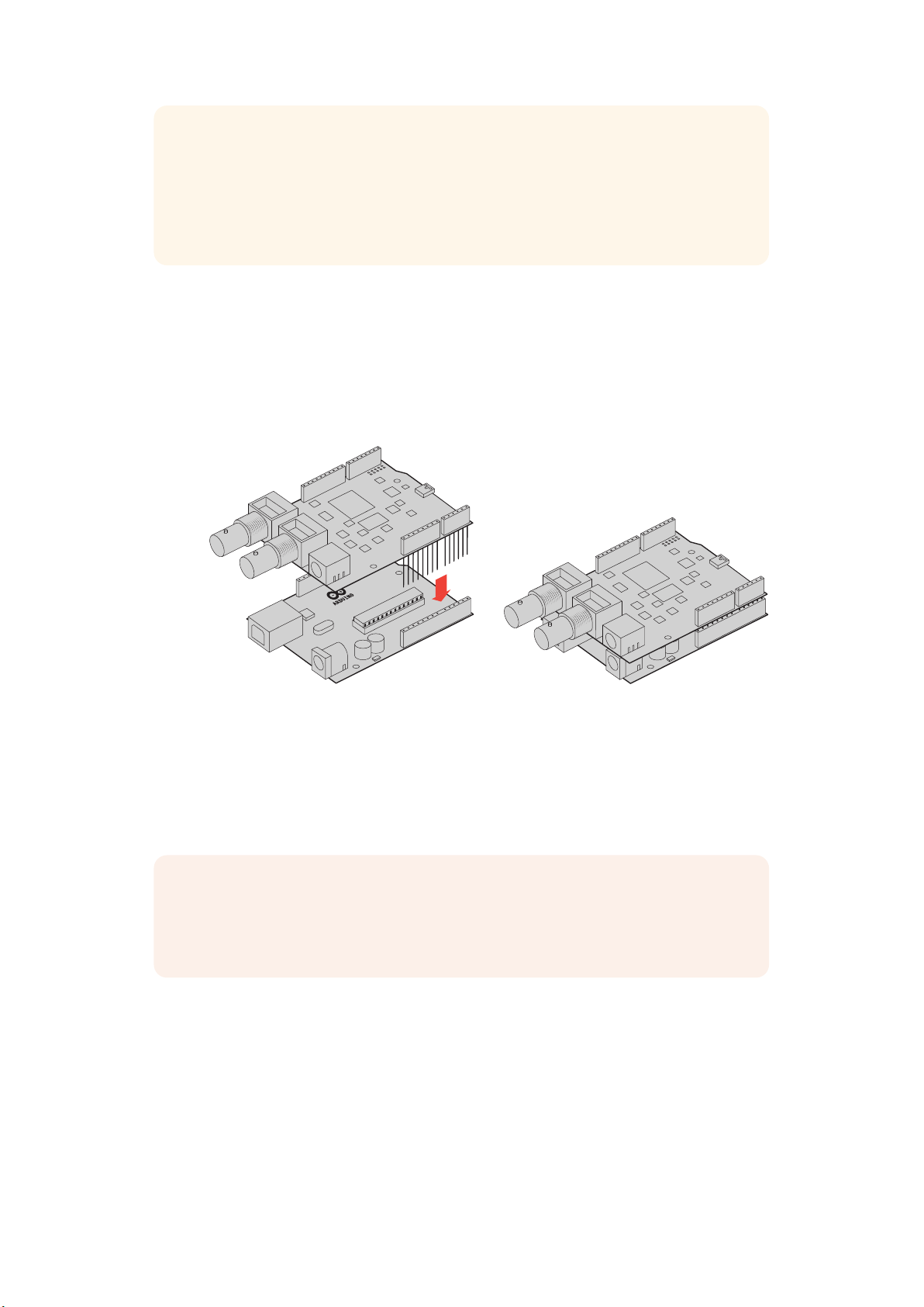
TIPP Um sicherzustellen, dass alle Pins Ihres Shields auf die weiblichen Buchsenleisten
des Arduino-Boards ausgerichtet sind, ist es ratsam, zunächst nur einen Pin mit jeder Leiste
zu verlöten. Platzieren Sie dann das Shield auf dem Arduino-Board und überprüfen Sie die
Ausrichtung der Pins. Sollten einige Leisten angepasst werden müssen, können Sie die
Lötstelle der jeweiligen Leiste erwärmen und sie neu ausrichten. Das ist sehr viel einfacher
als alle Stellen zu verlöten und anschließend Anpassungen vorzunehmen.
Anbringen an das Arduino-Board
Sobald die Stiftleisten mit Ihrem Shield verlötet sind, können Sie das 3G-SDI Shield auf Ihr ArduinoBoard aufstecken.
Halten Sie das Shield an beiden Seiten fest und richten Sie die Stiftleisten auf die Buchsenleisten Ihres
Arduino-Boards aus. Drücken Sie nun die Stifte vorsichtig in die Buchsen. Achten Sie darauf, dass sich
die Stifte dabei nicht verbiegen.
Wenn alle Stifte eingeführt sind, sollte eine feste und stabile Verbindung
zwischen dem Blackmagic Shield und dem Arduino-Board bestehen
Anschließen an das Stromnetz
Schließen Sie Ihr Blackmagic 3G-SDI Shield for Arduino an das Stromnetz an, indem Sie einfach einen
12V-Stromadapter in den 12V-Stromausgang Ihres Blackmagic Shields stecken.
HINWEIS Die Stromversorgung des Arduino-Boards liefert nicht ausreichend Strom für das
Blackmagic Shield. Wenn Sie jedoch das Blackmagic Shield an das Stromnetz anschließen,
wird auch der Arduino mit Strom versorgt. Stellen Sie also sicher, dass lediglich Ihr
Blackmagic Shield mit dem Netzstrom verbunden ist.
96Erste Schritte
Page 97
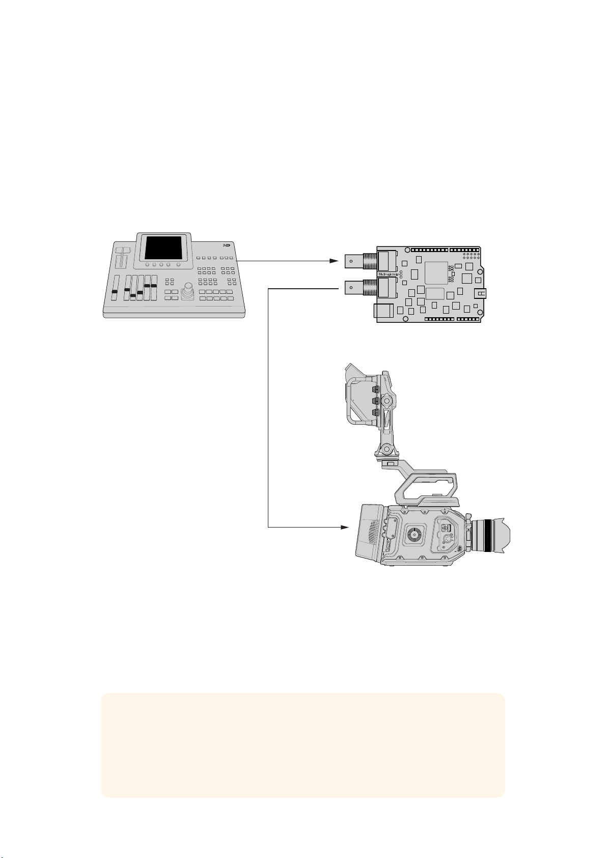
Anschließen an SDI-Equipment
Ist eine Verbindung zum Stromnetz hergestellt, können Sie das Blackmagic 3G-SDI Shield for Arduino
an Ihr SDI-Equipment anschließen. So schließen Sie bspw. einen Mischer und eine Blackmagic
URSA Mini an:
1 Schließen Sie den Programmausgang Ihres Mischers an den SDI-Eingang des Blackmagic
3G-SDI Shields an.
2 Verbinden Sie den SDI-Ausgang Ihres Blackmagic 3G-SDI Shields mit dem mit „PGM“
gekennzeichneten SDI-Programmeingang Ihrer URSA Mini.
Ein Anschlussdiagramm finden Sie weiter unten.
SDI IN
SDI OUT
Switcher
SDI ‘PGM’ Input
Blackmagic 3G-SDI Shield for Arduino
Blackmagic URSA Mini
Für den Einstieg war das schon alles.
Nun, da Ihr Shield auf dem Arduino-Board angebracht, es mit Strom versorgt und mit Ihrem
SDI-Equipment verbunden ist, können Sie die Produktsoftware sowie die Bibliotheksdateien
installieren, die Arduino-Software programmieren und mit dem Shield Ihr Equipment steuern.
Im weiteren Verlauf des Handbuchs finden Sie Informationen darüber, wie Sie die Produktsoftware
des Shields installieren und wo Sie die Arduino-Bibliotheksdateien speichern sollten, damit das Shield
mit Ihrem Arduino kommunizieren kann.
TIPP Ihr Blackmagic 3G-SDI Shield for Arduino können Sie auch für die Steuerung anderer
Blackmagic Design Produkte wie bspw. des Blackmagic MultiView 16 benutzen. Wenn Sie Ihr
Shield an Eingang 16 koppeln, können Sie so Tally-Umrandungen in der Mehrfachansicht
anzeigen. Wenn Sie Blackmagic URSA Mini Kameras verwenden, stellen Sie sicher, dass das
Grid-Overlay eingeschaltet ist, damit das Tally-Display im Suchmonitor aktiviert wird. Für
weitere Informationen sehen Sie in der Bedienungsanleitung Ihrer Blackmagic Kamera nach.
97Erste Schritte
Page 98

Softwareinstallation
HINWEIS Laden Sie die aktuellste Arduino IDE Software von www.arduino.cc herunter und
installieren Sie sie auf Ihrem Computer. Installieren Sie erst dann das Blackmagic 3G-SDI
Shield for Arduino Setup-Dienstprogramm.
Nachdem Sie die Arduino-Software installiert haben, können Sie die Blackmagic 3G-SDI
Shield Produktsoftware installieren.
Installieren der Produktsoftware
Blackmagic Shield for Arduino Setup dient der Aktualisierung der Produktsoftware Ihres Shields. Die
Produktsoftware kommuniziert mit dem Arduino-Board und steuert es mithilfe von ArduinoBibliotheksdateien. Diese Bibliotheksdateien werden zusammen mit der Setup-Software installiert. Sie
müssen lediglich den Ordner mit den Dateien kopieren und in den Arduino-Anwendungsordner
einfügen. Informationen zu den Bibliotheksdateien und wie diese installiert werden, finden Sie im
nächsten Kapitel dieses Handbuchs.
Wir empfehlen Ihnen, die aktuellste Blackmagic 3G-SDI Shield for Arduino Software herunterzuladen
und Ihr Shield auf den aktuellsten Stand zu bringen, damit Sie von neuen Funktionen und
Verbesserungen profitieren können. Die aktuellste Version steht im Blackmagic Design Support
Center unter www.blackmagicdesign.com/de/support zum Download bereit.
So installieren Sie die Produktsoftware unter Mac OS X:
1 Laden Sie die Blackmagic Shield for Arduino Software herunter und entpacken Sie sie.
2 Öffnen Sie das Speicherabbild und starten Sie das Blackmagic Shield for Arduino
Installationsprogramm. Folgen Sie den Anweisungen auf Ihrem Bildschirm.
3 Nachdem die aktuellste Version des Blackmagic Shield for Arduino Installationsprogramms
eingespielt wurde, versorgen Sie Ihr Blackmagic Shield mit Strom und verbinden Sie es per
USB-Kabel mit Ihrem Computer.
4 Starten Sie nun das Setup-Dienstprogramm und folgen Sie der Aufforderung auf Ihrem
Bildschirm für die Aktualisierung der Produktsoftware Ihres Shields. Sollte diese Aufforderung
nicht erscheinen, so ist Ihre Produktsoftware auf dem neuesten Stand. Keine weiteren
Aktionen Ihrerseits sind notwendig.
So installieren Sie die Produktsoftware unter Windows:
1 Laden Sie die Blackmagic Shield for Arduino Software herunter und entpacken Sie sie.
2 Nun sollten Sie einen Blackmagic Shield for Arduino Ordner sehen. Darin finden Sie dieses
Handbuch und das Blackmagic Shield for Arduino Installationsprogramm. Doppelklicken
Sie auf das Installationsprogramm und folgen Sie den Anweisungen zur Fertigstellung der
Installation auf dem Bildschirm.
3 Nachdem die aktuellste Version des Blackmagic Shield for Arduino Installationsprogramms
eingespielt wurde, versorgen Sie Ihr Blackmagic Shield mit Strom und verbinden Sie es per
USB-Kabel mit Ihrem Computer.
4 Starten Sie nun das Setup-Dienstprogramm und folgen Sie der Aufforderung auf Ihrem
Bildschirm für die Aktualisierung der Produktsoftware Ihres Shields. Sollte diese Aufforderung
nicht erscheinen, so ist Ihre Produktsoftware auf dem neuesten Stand. Keine weiteren
Aktionen Ihrerseits sind notwendig.
98Softwareinstallation
Page 99

Installieren der Arduino Bibliotheksdateien
Die Programme zur Steuerung Ihres Arduinos werden als Sketche bezeichnet. Ihr Blackmagic 3G-SDI
Shield for Arduino macht von Bibliotheksdateien Gebrauch, um das Schreiben von Sketchen zu
vereinfachen. Nach der Installation der Konfigurationssoftware Ihres Shields werden die
Bibliotheksdateien in einem Ordner namens „Library“ (Bibliothek) gespeichert. Kopieren Sie den
Ordner mit den Bibliotheksdateien und fügen Sie ihn in den „Library“-Ordner Ihres Arduino ein.
HINWEIS Während der Installation von Bibliotheken muss die IDE-Software
geschlossensein.
So installieren Sie Bibliotheksdateien unter Mac OS X:
1 Öffnen Sie „Blackmagic Shield for Arduino“ im Ordner „Programme“.
2 Öffnen Sie den Ordner „Library“ und führen Sie auf dem Ordner „BMDSDIControl“ einen
Rechtsklick aus. Wählen Sie anschließend „Kopieren“.
3 Gehen Sie nun zum Ordner „Dokumente“ und öffnen Sie den „Arduino“-Ordner.
4 Dort befindet sich ein Unterordner namens „Libraries“. Fügen Sie den Ordner
„BMDSDIControl“ in den Ordner „Libraries“ ein.
So installieren Sie Bibliotheksdateien unter Windows:
1 Öffnen Sie den Ordner „Programme“ bzw. „Blackmagic Shield for Arduino“.
2 Sie sehen nun einen Unterordner mit dem Namen „Library“. Öffnen Sie diesen und kopieren
Sie den Ordner mit dem Namen „BMDSDIControl“ per Rechtsklick.
3 Gehen Sie nun zum Ordner „Dokumente“ und öffnen Sie den „Arduino“-Ordner.
4 Dort befindet sich ein Unterordner namens „Libraries“. Fügen Sie den Ordner
„BMDSDIControl“ in den Ordner „Libraries“ ein.
Das ist schon alles, um die Blackmagic Design Bibliotheksdateien auf Ihrem Computer zu installieren.
Wenn Sie mit der Arduino-Software arbeiten, stehen Ihnen jetzt auch Blackmagic Design BeispielSketche zur Verfügung.
Öffnen Sie dazu einfach das Aufklappmenü „File“ (Datei) in der Menüzeile der Arduino-Software und
wählen Sie „Examples“ (Beispiele). Klicken Sie auf „BMDSDIControl“. Nun erscheint eine Liste mit
Beispiel-Sketchen zu Ihrer Auswahl.
Wenn sich die Bibliotheksdateien im korrekten Ordner befinden, kann Ihr Shield nun auf sie zugreifen
und mit dem Arduino-Board kommunizieren. Alles, was Sie dafür tun müssen, ist die Arduino-IDESoftware zu programmieren. Weitere Informationen finden Sie im Abschnitt „Programmieren von
Arduino-Sketchen“.
HINWEIS Wenn in Zukunft ein Update der Bibliotheksdatei mit Beispielen
herausgegebenwird, müssen Sie den alten „BMDSDIControl“-Ordner löschen und ihn
mitdem neuen Ordner ersetzen. Folgen Sie den Anweisungen oben.
99Installieren der Arduino Bibliotheksdateien
Page 100

Blackmagic Shield for Arduino Setup
Über die Blackmagic Shield for Arduino Setup Software können Sie Änderungen der Einstellungen an Ihrem
Shield vornehmen. Dazu gehören bspw. die I2C-Adresse und das Videoausgabeformat
Wenn Blackmagic Shield for Arduino Setup auf Ihrem Computer installiert ist, können Sie darüber die
Einstellungen Ihres Shields ändern. Dazu gehört die „I
identifiziert, damit das Arduino-Board mit ihm kommunizieren kann, und das „Video Format“
(Videoformat), das das Ausgabeformat Ihres Shields festlegt.
2
C Address“ (I2C-Adresse), die Ihr Shield
„I2C Address“
In seltenen Fällen ist es möglich, dass ein weiteres Shield, das auf Ihrem Blackmagic Shield
angebracht ist, dieselbe standardmäßige I
Konflikt. Sollte dies der Fall sein, können Sie die Standardadresse ändern.
2
C-Adresse wie Ihr Shield verwendet. Das führt zu einem
100Blackmagic Shield for Arduino Setup
 Loading...