

Black & Decker PI500BB, PI500BBCA Instruction Manual

132
UN AÑO DE GARANTÍA LIMITADA
El fabricante garantiza este producto contra defectos de materiales y mano de obra durante un período
de UN (1) AÑO a partir de la fecha de compra del producto por el comprador usuario final (“Período
de Garantía”). Si hay un defecto y una reclamación válida se recibe dentro del período de garantía, el
producto defectuoso puede ser reemplazado o reparado en el las siguientes maneras: (1) Devuelva
el producto al fabricante para reparación o reemplazo, a opción del fabricante. La prueba de compra
puede ser requerida por el fabricante. (2) Devuelva el producto a la tienda donde el producto fue
comprado para un intercambio (siempre y cuando se trate de un minorista participante). Devoluciones
al minorista deben hacerse dentro del plazo de póliza de devoluciones del minorista para intercambios
solamente (por lo general 30 a 90 días después de la fecha de compra). La prueba de compra puede
ser requerida por el minorista. Por favor consulte la póliza de devoluciones del minorista sobre
devoluciones que están fuera del plazo establecido para intercambios.
Esta garantía no se aplica a los accesorios, bombillos, fusibles y baterías; defectos a consecuencias
de desgaste normal; accidentes; daños y perjuicios sufridos durante el envío y manejo, alteraciones,
reparaciones o uso no autorizado, negligencia, abuso, y si no se siguen instrucciones para el cuidado
y mantenimiento del producto.
Esta garantía le otorga al comprador usuario final, derechos legales específicos y usted puede tener
otros derechos que varían de estado a estado o de provincia a provincia. Este producto no está
diseñado para uso comercial.
Por favor completar la tarjeta de registro del producto dentro de un plazo de 30 días a partir de la
fecha de compra y remitir a: Baccus Global LLC, One City Centre, 1 North Federal Highway, Suite 200,
Boca Raton, FL 33432. Baccus Global LLC, número de teléfono gratuito: 1-877-571 2391.
ESPECIFICACIONES
Energía continua máxima: 500 vatios
Capacidad de sobretensión: 1000 vatios
USB Output: 5 V CC (500mA)
Voltaje de entrada: 12.8 voltios
Voltaje de salida: RMS de CA de 115 voltios, 60 Hz aproximadamente
Alarma por voltaje bajo: <_ CC de 11,0 voltios
Parada por voltaje bajo: CC de 10,5 ± 0,3 voltios
Apagado térmico: Automático
Forma de onda: Onda senoidal modificada (MSW, por su sigla en inglés)
Conexión de salida: Tomacorrientes estándar de los Estados Unidos
Fusibles: Internos / Enchufe del accesorio de la CC de 12 voltios:
8 amperios
Cables de entrada: Cables del clip de la batería / cable del adaptador de
la C.C. 10 V
Temperatura de operación: 10 y 20 °C (50 y 68 °F)
Temperatura de almacenamiento: 0 a 40 °C (32 a 104 °F)
Humedad relativa/de operación: 5 a 95% no condensada
Importados por Baccus Global, One City Centre, 1 North Federal Highway, Suite 200, Boca Raton, FL 33432
www.Baccusglobal.com • 1-877-571-2391
32
500 WATT POWER INVERTER
WITH USB CHARGING PORT
INSTRUCTION MANUAL
Catalog Number PI500BB/PI500BBCA
SAVE THIS MANUAL FOR FUTURE REFERENCE.
Cat. # PI500BB/PI500BBCA July 2015
Copyright © 2015 Baccus Global LLC Printed in China
Thank you for choosing Black & Decker!
Go to www.Baccusglobal.com
to register your new product.
PLEASE READ BEFORE RETURNING THIS
PRODUCT FOR ANY REASON:
If you have a question or experience a problem with your Black & Decker purchase, go to
HTTP://WWW.BACCUSGLOBAL.COM
for instant answers 24 hours a day.
If you can’t find the answer or do not have access to the internet,
call 1-877-571-2391 from 9 a.m. to 5 p.m. EST, Mon. – Fri. to speak with an agent.
Please have the catalog number available when you call.
PI500BB_PI500BBCA_ManualENFRSP_073015.indd 32-1 7/30/2015 5:31:14 PM

2 3
Minimum Gauge for Cord Sets
Volts Total Length of Cord in Feet (Meters)
120V 0-25 26-50 51-100 101-150
(0-7.6m) (7.6-15.2m) (15.2-30.4m) (30.4-45.7m)
240V 0-50 51-100 101-200 201-300
(0-15.2m) (15.2-30.4m) (30.4-60.9m) (60.9-91.4m)
Ampere Rating
More Not more American Wire Gauge
Than Than
0 - 6 18 16 16 14
6 - 10 18 16 14 12
10 - 12 16 16 14 12
12 - 16 14 12 Not Recommended
WARNING: This product or its power cord contains lead, a chemical known to the State of
California to cause cancer and birth defect or other reproductive harm. Wash hands after handling.
WARNING: TO REDUCE THE RISK OF ELECTRIC SHOCK:
• Do not connect to AC distribution wiring.
• Do not make any electrical connections or disconnections in areas designated as IGNITION
PROTECTED. This includes DC cigarette lighter type plug connection or airplane adapter. This unit is
NOT approved for ignition protected areas.
• NEVER immerse the unit in water or any other liquid, or use when wet.
• Do not insert foreign objects into the AC outlet or the USB outlet.
WARNING: TO REDUCE THE RISK OF FIRE:
• Do not operate near flammable materials, fumes or gases.
• DO NOT expose to extreme heat or flames.
CAUTION: TO REDUCE THE RISK OF INJURY OR PROPERTY DAMAGE:
• Remove appliance plug from outlet before working on the appliance.
• DO NOT attempt to connect or set up the unit or its components while operating your vehicle. Not
paying attention to the road may result in a serious accident.
• Always use the inverter where there is adequate ventilation. Do not block ventilation slots.
• ALWAYS turn the inverter OFF by disconnecting it from the DC source when not in use.
• Make sure the nominal powering voltage is 12 volts DC, center connection positive (+).
• When using this unit in a vehicle, check the vehicle owner’s manual for maximum power rating and
recommended output. Do not install in engine compartment — install in a well ventilated area.
• Do not use with positive ground electrical systems.* Reverse polarity connection will result in a
blown fuse and may cause permanent damage to the inverter and will void warranty.
*The majority of modern automobiles, RVs and trucks are negative ground.
• Keep in mind that this inverter will not operate high wattage appliances or equipment that produces
heat, such as coffee makers, hair dryers, microwave ovens and toasters.
• Do not open the inverter — there are no user-serviceable parts inside.
• Do not use this inverter with medical devices. It is not tested for medical applications.
• Keep away from children.This is not a toy!
• Install and operate unit only as described in this Instruction Manual.
• Do not use this inverter on a watercraft. It is not qualified for marine applications.
• Check unit periodically for wear and tear. Do not disassemble the unit; return it to the manufacturer
when service or repair is required. Opening the unit may result in a risk of electric shock or fire, and
will void warranty.
• Read And Understand This Instruction Manual Before Using This Unit.
SAVE THESE INSTRUCTIONS
WARNING: TO REDUCE THE RISK OF INJURY:
Follow these instructions and those published by battery manfacturer and the manufacturer of any
equipment you intend to use with this unit. Review cautionary markings on these products and on
engine.
SAFETY GUIDELINES / DEFINITIONS
DANGER: Indicates an imminently hazardous situation which, if not avoided, will result in death or
serious injury.
WARNING: Indicates a potentially hazardous situation which, if not avoided, could result in death or
serious injury.
CAUTION: Indicates a potentially hazardous situation which, if not avoided, may result in minor or
moderate injury.
CAUTION: Used without the safety alert symbol indicates potentially hazardous situation which, if not avoided,
may result in property damage.
RISK OF UNSAFE OPERATION. When using tools or equipment, basic safety precautions should
always be followed to reduce the risk of personal injury. Improper operation, maintenance or
modification of tools or equipment could result in serious injury and property damage. There
are certain applications for which tools and equipment are designed. Black & Decker strongly
recommends that this product NOT be modified and/or used for any application other than for which
it was designed. Read and understand all warnings and operating instructions before using any tool or
equipment.
IMPORTANT SAFETY INSTRUCTIONS
WARNING: This product or its power cord contains lead, a chemical known to the State of
California to cause cancer and birth defect or other reproductive harm. Wash hands after handling.
GENERAL SAFETY WARNINGS AND INSTRUCTIONS FOR ALL
INVERTERS
READ ALL INSTRUCTIONS
WARNING: Read all instructions before operating product. Failure to follow all instructions listed
below may result in electric shock, fire and/or serious injury.
• Avoid dangerous environments. Don’t use appliances in damp or wet locations. Don’t use
appliances in the rain.
• Store idle appliances indoors. When not in use, appliances should be stored indoors in dry, and
high or locked-up place – out of reach of children.
• Don’t force appliance. It will do the job better and with less likelihood of a risk of injury at the rate
for which it was designed.
• Use right appliance. Do not use the appliance for any job except that for which it is intended.
• Disconnect appliances. Disconnect the appliance from the power supply when not in use,
before servicing, and when changing accessories such as blades and the like.
• PROPER COOLING IS ESSENTIAL WHEN OPERATING THE INVERTER. Do not place the unit near
the vehicle’s heat vent or in direct sunlight.
• Use of accessories and attachments. The use of any accessory or attachment not recommended
for use with this appliance could be hazardous. Note: Refer to the accessory section of this manual
for further details.
• Check damaged parts. A part that is damaged should be properly repaired or replaced by
manufacturer.
• Outdoor use extension cords. When an appliance plugged into this unit is used outdoors, use only
extension cords intended for use outdoors and so marked. Note that this inverter is not intended to
be used outdoors.
• Extension cords. Make sure your extension cord is in good condition. When using an extension
cord, be sure to use one heavy enough to carry the current your product will draw. An undersized
cord will cause a drop in line voltage resulting in loss of power and overheating. The following table
shows the correct size to use depending on cord length and nameplate ampere rating. If in doubt,
use the next heavier gauge. The smaller the gauge number, the heavier the cord.
PI500BB_PI500BBCA_ManualENFRSP_073015.indd 2-3 7/30/2015 5:31:14 PM
4 5
CAUTION – Rechargeable Devices
• Certain rechargeable devices are designed to be charged by plugging them directly into an AC
receptacle. These devices may damage the inverter or the charging circuit.
• When using a rechargeable device, monitor its temperature for the initial ten minutes of use to
determine if it produces excessive heat.
• If excessive heat is produced, this indicates the device should not be used with this inverter.
• This problem does not occur with most battery-operated equipment. Most of these devices use a
separate charger or transformer that is plugged into an AC receptacle.
• The inverter is capable of running most chargers and transformers.
CAUTION: INCOMPATIBLE PRODUCTS: Certain products contain power supplies or circuits that are
not compatible with a inverter using a modified sine wave output (such as this inverter) and may be
damaged by using this inverter.
If your product requires pure sine wave AC input power to function properly, the instruction manual
for your product could state this. If in doubt, you should contact your product manufacturer PRIOR
TO USE.
Some products must be powered from a pure sine wave power source, such as standard household
power, or a “pure sine wave” inverter in order to function properly.
Your product could be damaged by this inverter if it contains:
• Microwave ovens;
• Transformerless battery chargers
• Capacitive coupled power supplies
If an incompatible product is used with this inverter:
• The product might not operate at all, with no indication of failure. The product fuse might open as a
result of trying to use it with the inverter.
• The product might exhibit unusual operation (such as, intermittent operation, buzzing, and the like.)
Note: Some laptop computers may not operate with this inverter.
WARNING: If the product does not operate normally, to reduce the risk of injury or property
damage, turn the product off immediately and unplug it from the inverter
OPERATING INSTRUCTIONS
The Power Inverter must be connected only to batteries with a nominal output voltage of 12 volts. The
unit will not operate from a 6 volt battery and will sustain permanent damage if connected to a 24 volt
battery.
Always connect the PI500BB to the 12 volt DC power source before plugging any devices into the
unit.
The standard North American 115 volt AC and USB outlets allow simultaneous operation of multiple
devices. Simply plug the equipment into the unit and operate normally. Ensure that the wattage of all
equipment simultaneously plugged into the PI500BB does not exceed 500 watts continuous.
Connection to Power Source
The Power Inverter comes equipped with a DC Accessory Outlet Plug and Battery Clips for connection
to a power source.
CONNECTING TO A POWER SOURCE USING THE DC ACCESSORY OUTLET PLUG (UP TO 100W ONLY)
The DC Accessory Outlet Plug is suitable for operating the inverter at power
outputs up to 100 watts and has overload protection at 100W to prevent you
blowing the fuse if you connect a higher rated appliance. The tip of the plug
is positive (+) and the side contact is negative (–).
The opposite end of the DC Accessory Outlet Plug has a unique connector
fitted to it which will allow it to be only fitted into the socket on the rear
of the unit when there are NO battery clips connected to the unit. This is
a safety feature and the design of the plug also covers the positive (+)
terminal to
prevent both leads being connected at the same time.
Connect the inverter to the power source by inserting the DC Accessory Outlet Plug firmly into the
accessory outlet of a vehicle or other DC power source.
CAUTIONS
• Connect directly to power source using the included Battery Clips when operating above 100 watts.
INTRODUCTION
Thank you for purchasing the PI500BB 500 Watt Power Inverter with USB Charging Port. This
inverter can be used to operate personal electronics such as: laptop computers, digital/video cameras,
MP3 players, cell phones, PDAs, and more. It can also be used to recharge 110/120 volt AC devices
that have an appropriate recharging adapter with a standard North American two- or three-prong plug.
Please read this Instruction Manual carefully before use to ensure optimum performance and to avoid
damage to this product.
FEATURES
The unit has 2 LED indicators, 1 to show input conditions and 1 to show output conditions.
The input LED is located beside the power button and the output LED is located on the top of the
unit between the 2 AC outlets. A green LED indicates normal operation, a red LED indicates a fault
condition (refer to Troubleshooting Section of this manual.) and an amber LED indicates low input
voltage from the DC source. The AC and USB outlets are ready to use if you have a green output LED.
The Power Pushbutton turns the inverter ON and OFF. It can also be used to force reset of inverter
circuits by pressing it OFF (no LEDs are lit), then back ON again.
AC power is supplied through two standard North American three-prong type outlets. The outlets can
accommodate either two- or three-pin AC plugs.
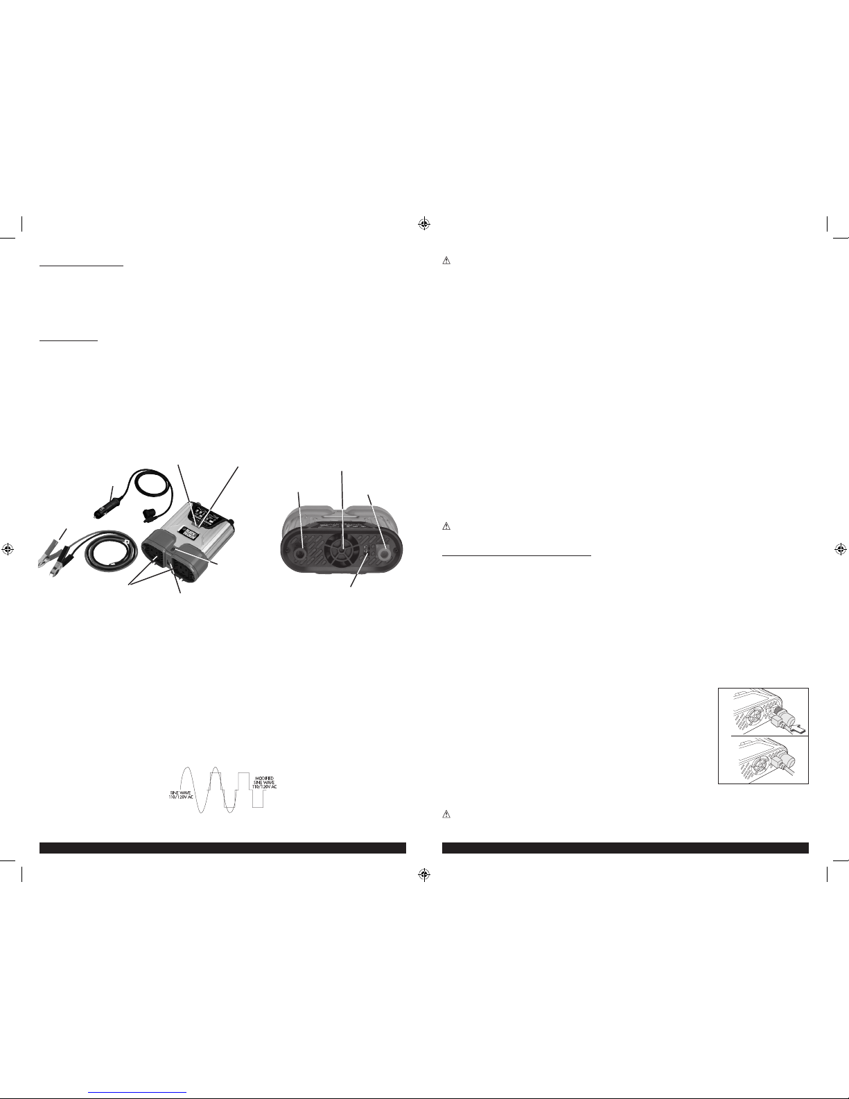
Controls and Functions
115 VOLT AC
OUTLETS
DC ACCESSORY
OUTLET PLUG
BATTERY CLIPS
(WITH CABLES)
OUTPUT LED
INDICATOR
INPUT
LED INDICATOR
USB OUTLET
ON/OFF
POWER BUTTON
HIGH-SPEED COOLING FAN
BACK OF UNIT
(BLACK) NEGATIVE
CABLE POST
(RED) POSITIVE
CABLE POST
DC ACCESSORY
OUTLET
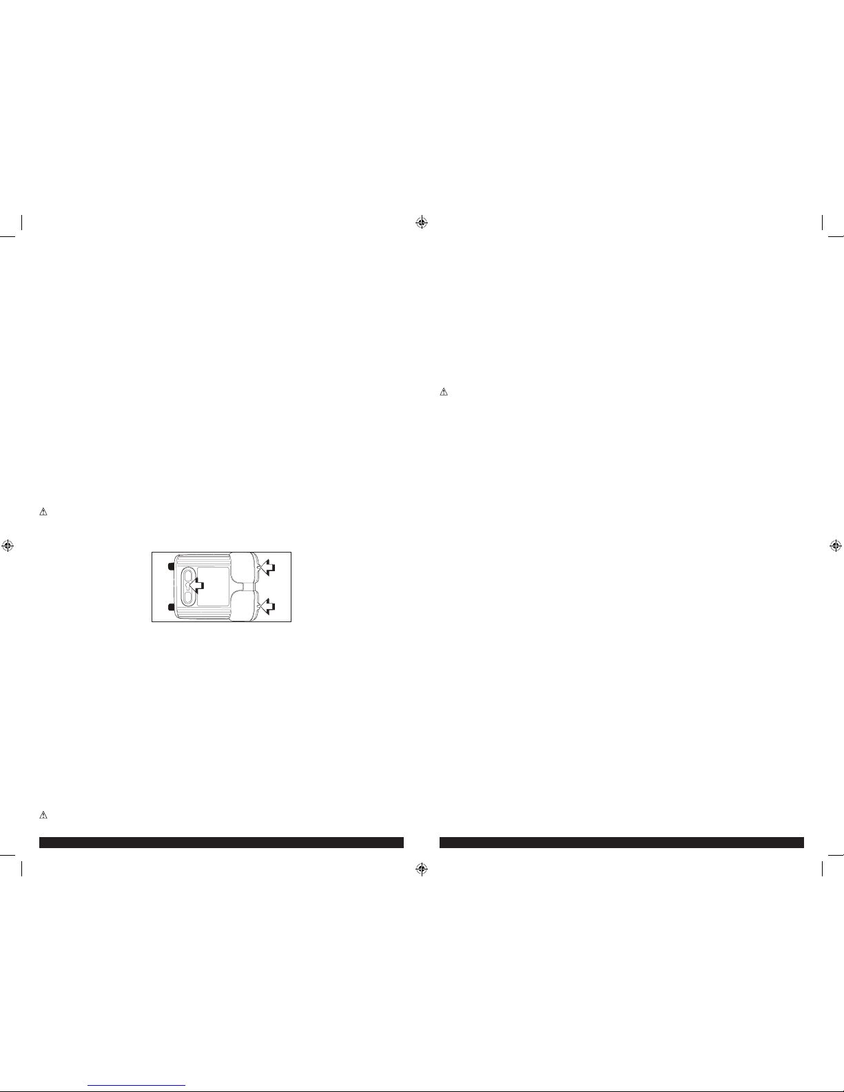
Power Inverter Output Waveform
NOTICE: THE OUTPUT OF THIS DEVICE IS NOT SINUSOIDAL. IT HAS A TOTAL HARMONIC
DISTORTION OF 36 PERCENT AND MAXIMUM SINGLE HARMONIC OF 28 PERCENT AT 100%
RATED LOAD.
The AC output waveform of this inverter is known as a modified sine wave. It is a stepped waveform
that has characteristics similar to the sine wave shape of utility power. This type of waveform
is suitable for most AC loads, including linear and switching power supplies used in electronic
equipment, transformers, and small motors.
The modified sine wave produced by this inverter has an RMS (root mean square) voltage of 115
volts. Most AC voltmeters (both digital and analog) are sensitive to the average value of the waveform
rather than the RMS value. They are calibrated for RMS voltage under the assumption that the
waveform measured will be a pure sine wave. These meters will not correctly read the RMS voltage of
a modified sine wave. Non-TRUE RMS meters will read about 20 to 30 volts low when measuring the
output of this inverter. For accurate measurement of the output voltage of this unit, use a TRUE RMS
reading voltmeter such as a Fluke 87, Fluke 8080A, Beckman 4410 or Triplett 4200.
115 Volt AC Output
PI500BB_PI500BBCA_ManualENFRSP_073015.indd 4-5 7/30/2015 5:31:16 PM
6 7
•The cable and fuse sizes given here are a general recommendation. You should always consult your
National Electrical Code prior to beginning each specific installation.
• Loose connectors may cause overheated wires and melted insulation.
• Check to make sure you have not reversed the polarity. Damage due to reversed polarity is not
covered by our warranty.
Connection To Load
The Power Inverter is equipped with dual standard North American three-prong type outlets. Plug the
cord from the equipment you wish to operate into the AC receptacle(s). Make sure the combined load
requirement of your equipment does not exceed maximum continuous power.
The Power Inverter is engineered to be connected directly to standard electrical and electronic
equipment in the manner described above. Do not connect the Power Inverter to household or RV
AC distribution wiring. Do not connect the Power Inverter to any AC load circuit in which the neutral
conductor is connected to ground (earth) or to the negative of the DC (battery) source.
WARNING: Do not connect to AC distribution wiring!
Rated Versus Actual Current Draw of Equipment
Most electrical tools, appliances, electronic devices and audio/visual equipment have labels that
indicate the power consumption in amps or watts. Be sure that the power consumption of the item to
be operated is below 500 watts. If the power consumption is rated in amps AC, simply multiply by the
AC volts (115) to determine the wattage.
Resistive loads are the easiest for the inverter to run; however, it will not run larger resistive loads
(such as electric stoves and heaters), which require far more wattage than the inverter can deliver.
Inductive loads (such as TVs and stereos) require more current to operate than do resistive loads of
the same wattage rating.
Inductive loads, i.e. power tools
Note: Some motors used in power tools, refrigerators and pumps require a very high surge current
to start. This inverter can handle a surge twice it’s rated power but some motors require more than
this when started. The inverter will not be harmed if you try to start such a product it will simply
shutdown on overload.
For safety reasons, the unit will simply shut down if it is overloaded. To restart the unit, simply
unplug all devices plugged into the unit; disconnect the unit from any 12 volt DC power source; then
reconnect the unit BEFORE plugging the appliance back in.
Operation of the 115 Volt AC Outlets
1. Connect the inverter to a functioning 12 volt DC power source as described in this Instruction
Manual. If using the 12 Volt DC Vehicle Accessory Adapter, rotate the vehicle accessory plug
slightly to make sure there is good contact. Make sure there is adequate space for proper
ventilation of the inverter.
2. Press the Power Pushbutton to turn the unit ON.
3. The green Power LED Indicator will light, indicating a proper connection. If either the yellow low
input voltage LED Indicator or red Fault LED Indicator lights, indicating a fault condition exists,
refer to the “Troubleshooting” section of this Instruction Manual.
4. If the Inverter does not work, make sure the ignition/accessory switch is actually powering the
accessory outlet. Some vehicles require the ignition switch to be turned on.
5. Plug the (110/120 volt AC) appliance into one of the Inverter’s three-prong AC outlet and operate
normally.
Note:
The Inverter will not operate appliances and equipment that generate heat, such as hair dryers, electric blankets, microwave ovens
and toasters.
Remember to disconnect the inverter from any power source when not in use.
Operation of the USB Charging Port
1. Connect the inverter to a functioning 12 volt DC power source as described in this Instruction
Manual. If using the 12 Volt DC Vehicle Accessory Adapter, rotate the vehicle accessory plug
slightly to make sure there is good contact. Make sure there is adequate space for proper
ventilation of the inverter.
2. Press the Power Pushbutton to turn the unit ON.
3. The green Power LED Indicator will light, indicating a proper connection. If either the yellow Input
Fault LED Indicator or red Output Fault LED Indicator lights, indicating a fault condition exists,
refer to the “Troubleshooting” section of this Instruction Manual.
• Do not use with positive ground electrical systems.
• Reverse polarity connection will result in a blown fuse and may cause permanent damage to the
inverter.
Notes:
Most vehicle accessory outlet circuits have fuses rated at 15 to 20 amps or greater. To operate at full wattage, either use the battery
clip cable (supplied) or directly wire to the power source with user-supplied wire and fuse. The majority of modern automobiles,
RVs and trucks are negative ground.
Once properly connected to a 12 volt DC power source and switched on, the green Power LED
Indicator lights indicating that the Inverter is functioning properly and the 100W logo will light up to
show you can only power devices up to 100W from this connection. If either the yellow low input
voltage LED Indicator or red Fault LED Indicator lights, indicating a fault condition exists, refer to the
“Troubleshooting” section of this Instruction Manual.
CONNECTING TO A POWER SOURCE USING THE PROVIDED BATTERY CLIPS
Use the provided Battery Clips (with cables) to connect the Power Inverter directly to the 12 volt
power source as follows:
1. Check to make sure the inverter’s Power Pushbutton has been pressed OFF (no LEDs are lit) and
that no flammable fumes are present in the installation area.
2. Connect the RED cable to the RED post on the back of the inverter. Connect the RED Battery Clip
to the POSITIVE terminal of the battery.
3. Connect the BLACK cable to the
BLACK
post on the back of the inverter. Connect the BLACK Battery
Clip to the NEGATIVE terminal of the battery.
4. Make sure that all connections between cables and terminals are secure.
5. Once properly connected to a 12 volt power source and switched on, the green power LED
indicator lights indicating that the inverter is functioning properly and both the 100W and 500W
logos will light up to show what devices you can power.
DIRECT HARDWIRING TO POWER SOURCE (OPTIONAL CONNECTION METHOD; HARDWARE NOT INCLUDED)
WARNING: It is not recommended to install with cables longer than 10ft as this can adversely effect
the operation of your inverter.
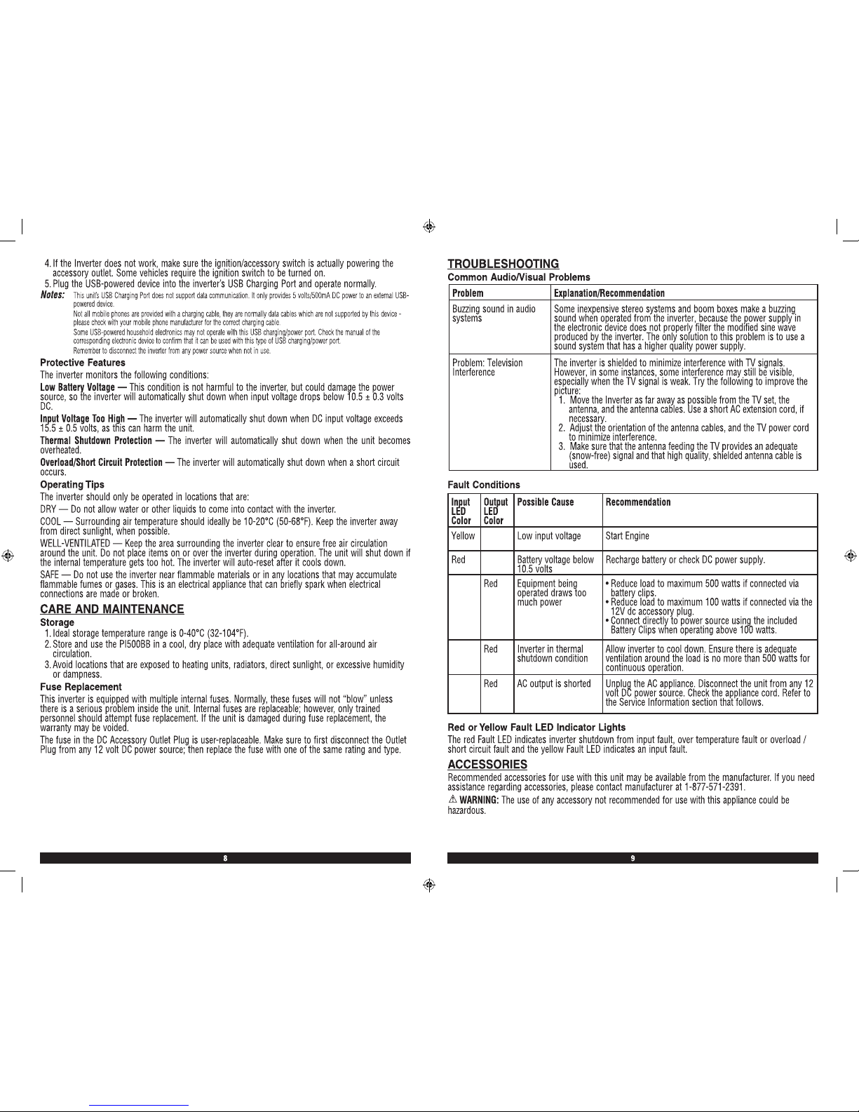
As this unit can be directly hard wired it has wall mount features built in to secure it in the desired
location. The diagram below shows you how to do this.
Use #6 AWG wire if the inverter to power source connection is 6 feet or less. For cable lengths up to
10ft use #4 AWG wire. In either case, protect the positive (+) wire from shorts by installing a 60 ANL
fuse or circuit breaker close to the DC power source (battery) terminal.
1. Check to make sure the inverter’s Power Pushbutton has been pressed OFF (no LEDs are lit) and
that no flammable fumes are present in the installation area.
2. Identify the positive (+) and negative (–) DC power source (battery) terminals.
3. Install a fuse holder or breaker close to the positive (+) terminal of the DC source (battery).
4. Connect a length of wire on one side of the fuse holder or circuit breaker. Connect the other end of
the wire to the positive (+) terminal of the inverter.
5. Connect a length of wire between the inverter’s negative (–) terminal and the DC power source
negative (–) terminal.
6. Connect a short length of wire to the other terminal of the fuse holder or circuit breaker. Mark it
“positive” or “+”.
7. Connect the free end of the fuse or breaker wire to the positive (+) terminal of the DC power
source (battery).
8. Insert a fuse appropriate to the inverter in the fuse holder.
9. Test the inverter by turning it on and plugging in a 100 watt lamp or equipment.
10. If the inverter is not properly operating, then refer to the Troubleshooting section of this manual.
CAUTION
PI500BB_PI500BBCA_ManualENFRSP_073015.indd 6-7 7/30/2015 5:31:16 PM
PI500BB_PI500BBCA_ManualENFRSP_073015.indd 8-9 7/30/2015 5:31:16 PM
 Loading...