

Page 1
Model: 9801
Programmable AC Power Source
USER MANUAL
Page 2

Page 3

Safety Summary
The following safety precautions apply to both operating and maintenance personnel and must
be followed during all phases of operation, service, and repair of this instrument.
Before applying power to this instrument:
• Read and understa nd the safety and opera ti onal informatio n in thi s m anual.
• Apply all the listed safety precautions.
• Verify that the volt a g e se l ector at the line power cord input is set to the correct line
voltage. Operating the instrument at an incorrect line voltage will void the warranty.
• Make all connections to the instrument before applying power.
• Do not operate the instrument in ways not specified by this manual or by B&K Precision.
Failure to comply with these precautions or with warnings elsewhere in this manual violates the
safety standards of design, manufacture, and intended use of the instrument. B&K Precision
assumes no liability for a customer’s failure to comply with these requirements.
Category rating
The IEC 61010 standard defines safety category ratings that specify the amount of electrical
energy available and the voltage impulses that may occur on electrical conductors associated
with these category ratings. The category rating is a Roman numeral of I, II, III, or IV. This rating
is also accompanied by a maximum voltage of the circuit to be tested, which defines the voltage
impulses expected and required insulation clearances. These categories are:
Category I (CAT I): Measurement instruments whose measurement inputs are not intended to
be connected to the mains supply. Th e voltages in the environment are typically derived from a
limited-energy transformer or a battery.
Category II (CAT II): Measurement instruments whose measurement inputs are meant to be
connected to the mains supply at a standard wall outlet or similar sources. Example
measurement envi ronmen ts are port a b l e tools and house hold appliance s.
Category III (CAT III): Measurement instruments whose measurement inputs are meant to be
connected to the mains installation of a building. Examples are measurements inside a
building's circuit breaker panel or the wiring of permanently-installed motors.
Category IV (CAT IV): Measurement instrume nts whos e measurement inputs are meant to be
connected to the primary power entering a building or other outdoor wiring.
i
Page 4

Do not use this instrument in an electrical environment with a higher category rating than what
is specified in this manual for this instrument.
You must ensure that each accessory you use with this instrument has a category rating equal to
or higher than the instrument's category rating to maintain the instrument's category rating.
Failure to do so will lower the category rating of the measuring system.
Electrical Power
This instrument is intended to be powered from a CATEGORY II mains power environment. The
mains power should be 110 V RMS or 220 V RMS. Use only the power cord supplied with the
instrument and ensure it is appropriate for your country of use.
Ground the Instrument
To minimize shock hazard, the instrument chassis and cabinet must be connected to an
electrical safety ground. This instrument is grounded through the ground conductor of the
supplied, three-conductor AC line power cable. The power cable must be plugged into an
approved three-conductor electrical outlet. The power jack and mating plug of the power cable
meet IEC safety standards.
Do not alter or defeat the ground connection. Without the safety gr ound connection, all
accessible conductive parts (including control knobs) may provide an electric shock. Failure to
use a properly-gr ounded approved ou tlet and the recommended three-conductor AC line power
cable may result in injury or death.
Unless otherwise stated, a ground connection on the instrument's front or rear panel is for a
reference of potential only and is not to be used as a safety ground.
Do not operate in an explosive or flammable atmosphere
ii
Page 5
Do not operate the instrument in the presence of flammable gases or vapors, fumes, or finelydivided particulate s.
The instrument is designed to be used in office-type indoor environments. Do not operate the
instrument
• In the presence of noxious, corrosive, or flammable fumes, gases, vapors, chemicals, or
finely-divided particulates.
• In relative humidity conditions outside the instrument's specifications.
• In environments where there is a danger of any liquid being spilled on the instrument or
where any liquid can condense on the instrument.
• In air temperatures exceeding the specified operating temperatures.
• In atmospheric pressures outside the specified altitude limits or where the surrounding
gas is not air.
• In environments with restricted cooling air flow, even if the air temperatures are within
specifications.
• In direct sunlight.
This instrument is intended to be used in an indoor pollution degree 2 environment. The
operati ng t e mpera ture r a nge is 0 °C to 40 °C and the op erating hum idity range is up to 80%
relative humidity with no condensation allowed.
Measurements made by this instrument may be outside specifications if the instrument is used
in non-office-type environments. Such environments may include rapid temperature or
humidity changes, sunlight, vibration and/or mechanical shocks, acoustic noise, electrical noise,
strong ele c tr i c fi elds, or strong magnetic fie lds.
Do not operate instrument if damaged
If the instrument is damaged, appears to be damaged, or if any liquid, chemical, or other
material get s on or in side the instrument, remove the instrument's power cord, remove the
instrument from service, label it as not to be operated, and return the instrument to B&K
Precision for repair. Notify B&K Precision of the nature of any contamination of the instrument.
iii
Page 6

Clean the instrument only as instructed
Do not clean the instrument, its switches, or its terminals with contact cleaners, abrasives,
lubricants, solvents, acids/bases, or other such chemicals. Clean the instrument only with a
clean dry lint-free cloth or as instructed in this manual.
Not for critical applications
This instrument is not authorized for use in contact with the human body or for use as a
component in a life-support device or system.
Do not touch live circuits
Instrument cover s m ust not be removed by operating personnel. Component replacement and
internal adjustments must be made by qualified service-trained maintenance personnel who are
aware of the hazards involved when the instrument's covers and shields are removed. Under
certain conditions, even with the power cord removed, dangerous voltages may exist when the
covers are removed. To avoid injuries, always disconnect the power cord from the instrument,
disconnect all other connections (for example, test leads, computer interface cables, etc.),
discharge all circuits, and verify there are no hazardous voltages present on any conductors by
measurements with a properly-operating voltage-sensing device before touching any internal
parts. Verify the voltage-sensing device is working properly before and after making the
measurements by testing with known-operating voltage sources and test for both DC and AC
voltages. Do not attempt any service or adjustment unless another person capable of rendering
first aid and resuscitation is present.
Do not insert any object into an instrument's ventilation openings or other openings.
Hazardous voltages may be present in unexpected locations in circuitry being tested when a
fault condition in the circuit exists.
iv
Page 7
Fuse replacement
Fuse replacement must be done by qualified service-trained maintenance personnel who are
aware of the instrument's fuse requirements and safe replacement procedures. Disconnect the
instrument from the power line before replacing fuses. Replace fuses only with new fuses of the
fuse types, voltage ratings, and current ratings specified in this manual or on the back of the
instrument. Failure to do so may damage the instrument, lead to a safety hazard, or cause a fire.
Failure to use the specified fuses will void the warranty.
Servicing
Do not substitute parts that are not approved by B&K Precision or modify this instrument.
Return the instrument to B&K Precision for service and repair to ensure that safety and
performance features are maintained.
Cooling fans
This instrument contains one or more cooling fans. For continued safe operation of the
instrument, the air inlet and exhaust openings for these fans must not be blocked nor must
accumulated dust or other debris be allowed to reduce air flow. Maintain at least 25 mm
clearance around the sides of the instrument that contain air inlet and exhaust ports. If
mounted in a rack, position power devices in the rack above the instrument to minimize
instrument heating while rack mounted. Do not continue to operate the instrument if you
cannot verify the fan is operating (note some fans may have intermittent duty cycles). Do not
insert any object into the fan's inlet or outlet.
Use correctly sized wires
To connect a load to the power supply, use a wire diameter large enough to handle the
maximum continuous output short-circuit current of the power supply without the wire
overheating.
v
Page 8

For continued safe use of the instrument
• Do not place heavy objects on the instrument.
• Do not obstruct cooling air flow to the instrument.
• Do not place a hot soldering iron on the instrument.
• Do not pull the instrument with the power cord, connected probe, or connected test
lead.
Do not move the instrument when a probe is connected to a circuit being tested.
vi
Page 9
This product is subject to Directive 2002/96/EC of the
Compliance Statements
Disposal of Old Electrical & Electronic Equip m e nt (A pplicable in the European
Union and other European countries w ith separate collection systems)
European Parliament and the Council of the European Union
on waste electrical and electronic equipment (WEEE), and in
jurisdictions adopting that Directive, is marked as being put
on the market after August 13, 2005, and should not be
disposed of as unsorted municipal waste. Please utilize your
local WEEE collection facilities in the di sposition of this
product and otherwise observe all applicable requirements.
vii
Page 10

CE Declaration of Conformity
The power supply meets the requirements of 2006/95/EC Low Voltage Directive and 2004/108/EC
Electromagnetic Compatibility Directive with th e following standards.
Low Voltage Directive
- EN61010-1: 2001
EMC Directive
- EN 61000-3-2: 2006
- EN 61000-3-3: 1995+A1: 2001+A2: 2005
- EN 61000-4-2 / -3 / -4 / -5 / -6 / -11
- EN 61326-1: 2006
viii
Page 11
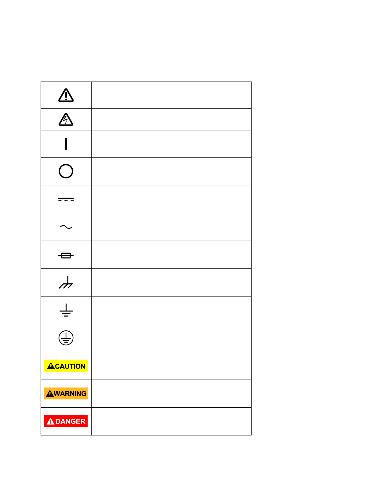
Refer to the user manual for warning information
damage to instrument.
On (Supply). This is the AC mains
instrument.
instrument.
Safety Symbols
to avoid hazard or personal injury and prevent
Electric Shock hazard
connect/disconnect swi tch on the front of the
Off (Supply). This is the AC mains
connect/disconnect swi tch on the front of the
DC current
Alternating curre nt
Fuse Symbol
Chassis (earth ground) symbol
Ground terminal
Protective earth ground
CAUTION indicates a hazardous situation which, if
not avoided, will result in minor or mode rate injury
WARNING indicates a hazardous situation which, if
not avoided, could result in death or serious injury
DANGER indicates a hazardous situation which, if
not avoided, will result in death or serious injury.
ix
Page 12

Table of Contents
Safety Summary ................................................................................................... i
Compliance Statements ............................................................................................................. vii
Safety Symbo ls ............................................................................................................................ ix
1 General Information ..................................................................................... 1
1.1 Product Overview ............................................................................................................. 1
1.2 Package Contents ............................................................................................................. 1
1.3 Product Dimensions ......................................................................................................... 2
1.4 Front Panel Overview ....................................................................................................... 4
Front Panel Description ........................................................................................................... 4
1.5 Rear Panel Overview ........................................................................................................ 5
Rear Panel Description ............................................................................................................ 5
1.6 Display Overview .............................................................................................................. 6
Display Description .................................................................................................................. 6
2 Getting Started ............................................................................................. 7
2.1 Input Power and Fuse Requirements ............................................................................... 7
Input Power ............................................................................................................................. 7
Fuse Requirements .................................................................................................................. 8
Fuse Replacement ................................................................................................................... 8
2.2 Output Connections ......................................................................................................... 9
2.3 Preliminary Check ........................................................................................................... 11
Self-test Errors ....................................................................................................................... 12
Output Check ......................................................................................................................... 12
Check Model and Firmware Version ..................................................................................... 12
3 Front Panel Operatio n ................................................................................ 14
3.1 Menu Options ................................................................................................................. 14
How to Access the Menu ....................................................................................................... 14
3.2 Configure Voltage and Frequency Output ...................................................................... 15
Setting Voltage ...................................................................................................................... 15
Output Range ........................................................................................................................ 16
Setting Frequency .................................................................................................................. 16
x
Page 13

Setting Phase Angle .............................................................................................................. 16
3.3 SYSTEM Menu ................................................................................................................ 17
Restore Factory Default Settings ........................................................................................... 17
Configure Power-On Settings ................................................................................................ 19
Configure Power-Out State ................................................................................................... 19
Enable/Disable Key Sound ..................................................................................................... 19
Configure Trigger Source ....................................................................................................... 19
Communication Setup ........................................................................................................... 20
Save/Recall Instrument Settings ........................................................................................... 22
3.4 CONFIG Menu ................................................................................................................. 23
Voltage Limits ........................................................................................................................ 23
Frequency Limits ................................................................................................................... 24
Current Protection ................................................................................................................. 24
External BNC ......................................................................................................................... 25
3.5 Dimmer Output Simulation ............................................................................................ 27
3.6 List Mode ........................................................................................................................ 28
Configure List Setting ............................................................................................................ 28
Edit List File ........................................................................................................................... 29
Recall and Run Program ........................................................................................................ 31
Power Line Disturbance Simulation (PLD) ............................................................................. 32
3.7 Sweep Mode ................................................................................................................... 34
Edit Sweep File ...................................................................................................................... 35
Recall and Run Sweep ........................................................................................................... 35
3.8 Key Lock .......................................................................................................................... 36
4 Remote Operation ...................................................................................... 37
4.1 Interface Connectio n ...................................................................................................... 37
RS-232 ................................................................................................................................... 37
USBTMC ................................................................................................................................. 37
LAN ........................................................................................................................................ 37
4.2 Remote Commands ........................................................................................................ 38
5 Trouble shooting Guide ............................................................................... 39
General .................................................................................................................................. 39
xi
Page 14

Remote Control ..................................................................................................................... 39
6 Specifications ............................................................................................. 40
Calibration ................................................................................................................................. 41
SERVICE INFORMATION ..................................................................................... 42
LIMITED THREE-YEAR WARRANTY ..................................................................... 43
xii
Page 15

1 General Information
1.1 Product Overview
The B&K Precision model 9801 is a high performance AC power source with the capability of
producing up to 300 VAC at a maximum power output of 300 VA. The instrument is equipped
with powerful featu re s such a s l ist mo d e , sweep mode, power line disturbance (PLD) simulation,
and dimmer output simulation. Other feature s include an easy-to-read VFD display, userfriendly controls and a numeric keypad that allows for easy configurations from the front panel.
Standard USB, RS232, and LAN interfaces included on the rear panel provide flexibility for
remote operation of the power supply.
Features:
• High accuracy and resolution
• Compact, high dens i ty 2U rackmount form factor
• Programmable frequency (45 Hz – 500 Hz)
• Standard USBTMC, RS232, and LAN
• Power line disturbance simulation
• Dimmer output simulation
• Adjustable phase angle
• List mode to generate surge, sag and other line disturbance simulations
• OVP, OPP, OCP, and OTP protection features
1.2 Package Contents
Please inspect the instrument mechanically and electrically upon receiving it. Un pack all items
from the shipping carton, and check for any obvious signs of physical damage that may have
occurred during transportation. Report any damage to the shipping agent immediately. Save the
original packing carton for possible future reshipment. Every power supply is shipped with the
follo wing contents:
• 1 x 9801 AC Power Source
• 1 x User Manual
• 1 x AC Power Cord
• 1 x Certificate of Calibration
• 1 x Test Report
Verify that all items above are included in the shipping container. If anything is missing, please
contact B&K Precision.
1
Page 16
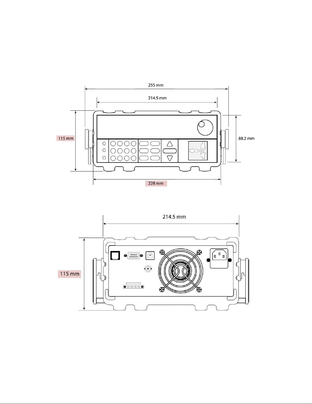
1.3 Product Dimensions
The 9801 power supply is designed to fit in a standard 19-inch half rackmount and is of 2U si ze.
Note: All dimensions in the figures below are measured in millimeters (mm).
Figure 1.1 – Front Panel View
Figure 1.2 - Rear Panel View
2
Page 17
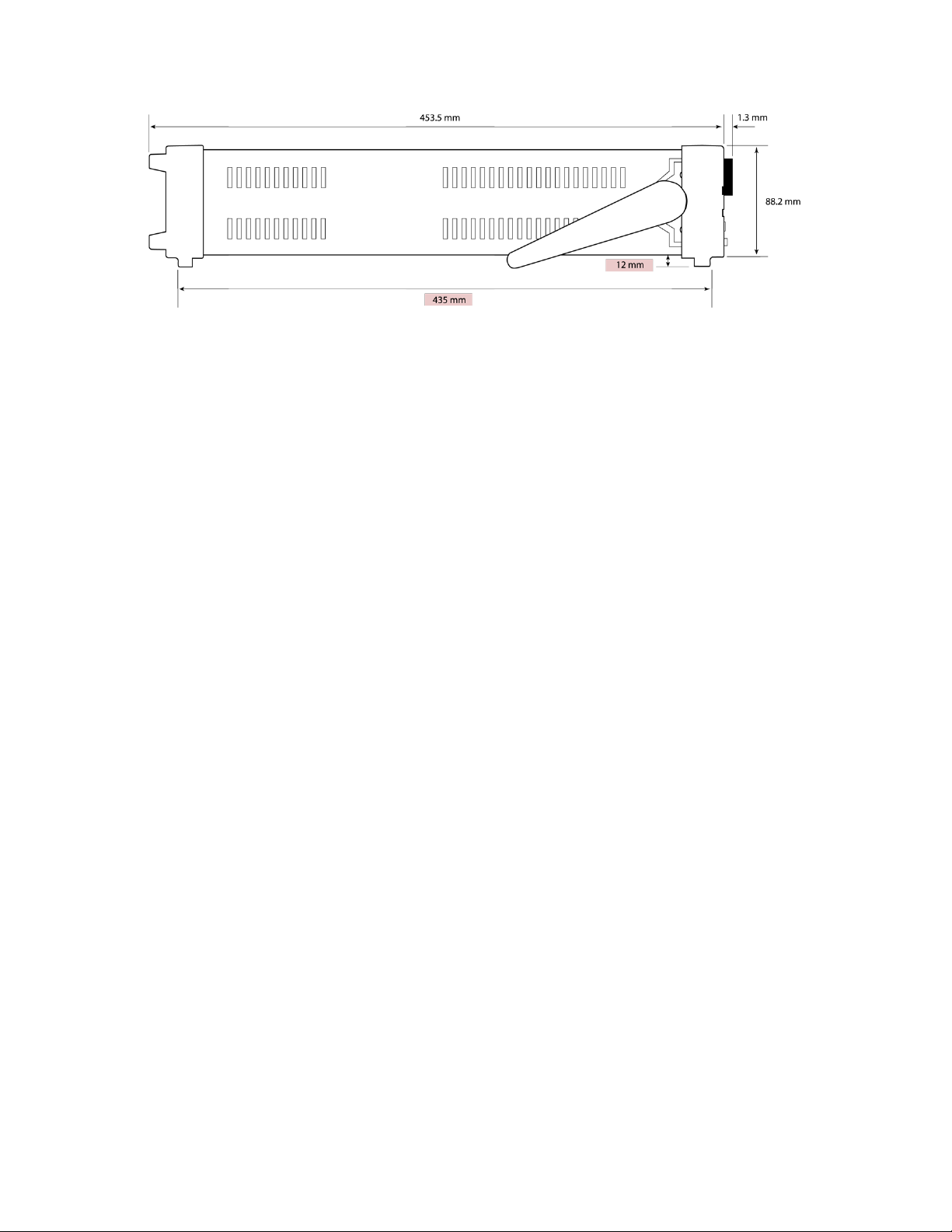
Figure 1.3 – Side View
3
Page 18
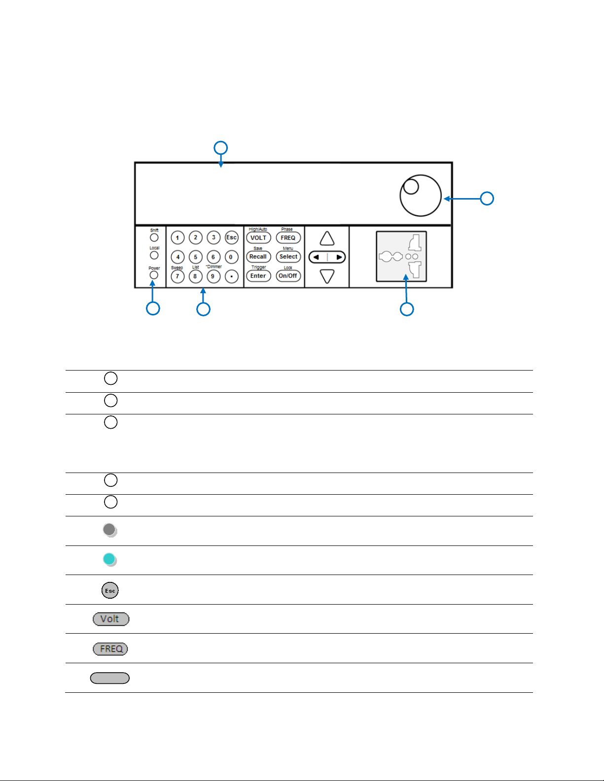
Numeric keypad
9: Dimmer – Configure the di mm er settings
Local button
Set the instrument back to local mode.
Shift button
Enables access to secondary functions o f some buttons.
Esc button
Used to exit menu settings.
VOLT / High / Auto button
Set the output voltage or range between high and auto.
FREQ / Phase button
Set the output fre que ncy or phase
Recall
Recall / Save button
Used to save or recall instrument settings.
1 2 3 5 4
1
2
3
4
5
1.4 Front Panel Overview
Front Panel Description
VFD display
Power On/Off switch
7: Sweep – Configure and enable the sweep settings
8: List – Configure and enable the l ist function
AC output socket
Rotary knob
Figure 1.4 – Front Panel
4
Page 19

Select / Menu button
power(in Volt-ampere)/peak current(Apk) display or access t he m ai n m e nu.
EnterEnter
Enter / Trigger button
Used to confirm setting/parameter changes or to send a trigger manually.
On/Off
On/Off / Lock button
Controls the output state or locks the fro nt panel button.
BNC Interface Terminal
Used for external trigger and other functionality (see Exte r nal BNC)
2
3 4 6
7
8
1
L N
5
1
2 3 4 5 6 7 8
Toggles between output power(in Watts)/power factor(PF) or output
Navigation arrow keys
1.5 Rear Panel Overview
Figure 1.5 - Rear Panel
Rear Panel Description
LAN Inte rface
RS-232 Interface
USB Interface
AC Output Terminal
Cooling Fans
AC Input Receptacle
Fuse Box
5
Page 20

300.0V
0.0mA
0.00W
OFF Rmt SQR Error Trig Prot Auto * Shift
PF = 0.000
1 2 3
6
500
0.1 s
4
5
Figure 1.6 – Display Overview
1 2 3
4
5
6
1.6 Display Overview
Display Description
Programmed/Measured Voltage
Measured Power Output
Settings Display
Measured Current
Output ON timer
Programmed Frequency
OFF Indicates output is disabled
Rmt Indicates remote m ode
SQR Indicates service request
Error Indicates an error has occurred
Trig Indicates waiting for trigger (for list operation)
Prot Indicates protection trip for over voltage or over temperature
Auto Indicates power supply is in auto range
* Indicates dimmer function is enabled
Shift Indicates shift mode (for access t o s e condary button functions)
Lock Indicates key lock is enabled
6
Page 21

voltage. After changing the line voltage setting, ensure
types for the selected line voltage before applying line
110 or 220 selector
110
Bottom of the unit
2 Getting Started
Before connecting and powering up the instrument, please review the instructions in this
chapter.
2.1 Input Power and Fuse Requirements
Input Power
This instrument can operate from an AC source that meet the following requirements::
AC Voltage: 110 V ± 10% or 220 V ± 10 %
Frequency: 47 Hz – 63 Hz
Use the line voltage selector on the bot tom of the unit to set the input voltage of the
instrument between 110 V and 220 V.
Figure 2.1 – Line Voltage Selector Location
Disconnect all cables including the power cord from
the instrument when changing the instrument's line
the instrument has fuses of the proper ratings and
7
Page 22

power.
SHOCK HAZARD
third conductor. Verify that your power outlet is of the
to earth ground to prevent electric shock.
warranty.
Model
Fuse Specification (110 V)
Fuse Specification (220 V)
9801
T 10 A, 250 V
T 6.3 A, 250 V
The power cord provides a chassis ground through a
three-conductor type with the correct pin connected
Before connecting to an AC outlet or external power source, be sure that the power switch is in
the OFF position and verify that the AC power cord, including the extension line, is compatible
with the rated voltage/current and that there is suff i c i ent ci rcuit capacity for the power supply.
Once verified, connect the cable firmly.
The included AC power cord is safety certified for this
instrument operating in rate d range . To change a
cable or add an extension cable, be sure that it can
meet the required power ratings for this instrument.
Any misuse with wrong or unsafe cables will void the
Fuse Requirements
An AC input fuse is necessary when powering the instrument. R efer to the table below for the
fuse requirements.
Table 2.1 – AC Input Fuse Table
Fuse Replacement
Follow the steps below to replace or c heck the fuse.
1. Locate the fuse box in the rear panel, beneath the AC input recep tacle.
2. With a small flat blade screwdriver, insert the blade into the fuse box slit to pull and
slide out the fuse box as indicated below.
3. Pull out the g la s s tube fuse inside to check and repla ce (if necessary) for the desired line
voltage operation.
4. Insert the fuse capsule in the same orientation and location.
5. The fuse capsule will now be locked and secured.
8
Page 23

current.
SHOCK HAZARD
connections have no accessible live parts. Ensure that
Fuse box slit
Fuse
box
Check/Remove Fuse
L
N
E
Figure 2.2 – Fuse Box
2.2 Output Connections
The main front panel is equipped with a universal AC outlet, which accepts all standard types of
common AC power plugs. This AC output is isolated from the AC power input of the instrument.
Figure 2.3 – Universal AC Output Socket
Before connecting wires to the output terminals, turn
OFF the power supply to avoid damage to the
instrument and the device under test (DUT). For
safety, load wires must have a wire gauge size large
enough to prevent overheating when the power
supply operates at maximum short circuit output
Hazardous voltages may exist at the outputs and the
load connections when using this power supply. To
protect personnel against accidental contact with
hazardous voltages, ensure that the load and its
9
Page 24

the load wiring ins ul ation rating is great er than to the
maximum output voltage of the power supply.
supply operates at maximum short circuit output
China
E
N L
America, Canada
Europe
England
L N
The following types of AC power plugs are accepted.
Figure 2.4 – Region Specific Power Cord Types
This unit also features a rear AC output terminal block which accepts a wire connection. This
terminal block is also isolated fro m the AC power input of the instrument.
Figure 2.5 – Rear Panel AC Output Terminal
Before connecting wires to the output terminals, turn
OFF the power supply to avoid damage to the
instrument and the device under test (DUT). For
safety, load wires must have a wire gauge size large
enough to prevent overheating when the power
10
Page 25

current.
SHOCK HAZARD
maximum output voltage of the power supply.
BIOS Ver 1.10
System Selftest . . . .
. .
Hazardous voltages may exist at the outputs and the
load connections when using this power supply. To
protect personnel against accidental contact with
hazardous voltages, ensure that the load and its
connections have no accessible live parts. Ensure that
the load wiring insulation rating is greater than to the
2.3 Preliminary Check
Complete the following steps to verify that the power supply is ready for use.
1. Verify AC Input Voltage
Verify and check to make sure proper AC voltages are available to power the instrument.
The AC voltage range must meet the acceptable specification as explained in “2.1 Input
Power and Fuse Requirements”.
2. Connect Power and Self-Test
Connect AC power cord to the A C rec eptacle in the rear panel and pres s the power
switch to the |(ON) position to turn ON the instrument. It will display the BIOS version
then run through a self-test procedure with the screen shown in below:
If the EEPROM was damaged or the latest operation data in the EEPROM was lost, the
VFD will highlight the “Error” indicator. Accessing the “Info” menu will give detailed error
information. If self-test passes, VFD will display:
11
Page 26
EnterEnter
EnterEnter
On/Off
300.0V
0.0mA
0.00W
OFF Auto
PF = 0.000
500
0.1 s
Self-test Errors
If any erro rs occur during power up, please contact B&K Precision.
Output Check
Voltage and Frequency Check
Follow the steps below to chec k basic voltage output with no load connected.
1. Turn on the AC power source. The display will show the OFF annunc i ato r above the
voltage display.
2. Using the numeric keypad or the rotary knob, enter a voltage value. The voltage display
will show the value you entered. If entering with the numeric keypad, press
first, then enter the value and pr ess
3. Press the button and set the frequenc y using the numeric keypad or the rotar y
knob. If entering with the numeric keypad, make sure to press
value.
4. Enable the output by pressing
annunciator will disappear and the output timer will begin counting.
5. Once the output is ON, the voltage display will show the measured voltage at the output,
which may fluctuate slightly from the voltage value entered in the previous step.
6. (Optional) You may also verify the output voltage and frequency by connecting the (L)
and (N) terminals on the rear panel to an external multimeter or an oscilloscope. Under
normal operation, the measured value will be equal to or within the entered voltage
and frequency value.
7. Ensure that the voltage can be adjusted from zero to the full rated output of the unit
and verify the full frequency range is within specifications.
.
after entering a
, and the button will be illuminated. The OFF
Check Model and Firmware Version
The model and firmware version ca n be verified by using the *IDN? query remote command. It
can also be found from w ithi n the menu sy stem by f ol lowing thes e steps:
12
Page 27

EnterEnter
PRODUCT INFO:
Model: 9801 Ver: 0.02 – 0.01
1. Press (Shift) and press (Menu) to enter the menu system.
2. Press the arrow two times until INFO is blinking. Press
will show the following screen:
3. The model is shown above as 9801, and the firmware version is shown as 0.02 – 0.01.
4. Press to exit the menu and return to the normal display.
, and the display
13
Page 28

SYSTEM
Init
Reset power supply settings to factory default values
Power-On
Configure power-on parameters
Power-Out
Configure power-on output state
Buzzer
Enable/Disable key sound
Trigger
Configure Trigger
Communication
Select communication interface
CONFIG
Volt-Min
Set minimum voltage limits
Volt-Max
Set maximum voltage limits
Freq-Min
Set minimum frequency limits
Freq-Max
Set maximum frequency limits
Irms-Protect
Configures current RMS protection setting
BNC-Set
Select external BNC connection setup
Ipeak-Protect
Configures current peak pr otection point
Dimmer
Configures dimmer outp ut fu nction
List-Set
Configure list start trigger
INFO
Error Info
Displays error information (Shown only when an error has
occurred)
Product Info
Displays model and firmware version
Product SN
Displays serial number
Record Info
Displays instrument information
EnterEnter
3 Front Panel Operation
3.1 Menu Options
All settings and parameters can be configured from the menu of the power supply. To access
the menu, press (Shift) and press (Menu) .
The menu is divided into the following sections and organized as follows:
How to Access the Menu
Before using the instrument, it is important to be familiarized with its menu structure and learn
how to view or change sett in g s and parameters. Follow the steps below to guide you in
selecting menu options.
1. From the normal display, press (Shift) and press (Menu) to enter the menu.
2. The selected item will be blinking. Use keys to move through the menu
selections.
3. When the desired me nu section is blink ing , pr es s
to access its menu settings.
14
Page 29
EnterEnter
EnterEnter
EnterEnter
EnterEnter
SYSTEM
Init Power-On Power-On
4. Below is the display when SYSTEM is selected.
5. The selected item will be blinking. Use keys to move through the menu items.
When there is a on the right side of the display, that means there are more menu
items available to select from. Similarly, a will appear on the left side of the display
when there are menu items to the left. Use the keys accordingly to s el ect the
desired menu item.
6. Press
7. There may be parameters or options to select within each menu item. Follow the same
instructions as described in the previous steps to select them. To save changes to a
setting, press
to access the selected menu item.
.
8. To exit the menu at any time, press twice.
3.2 Configure Voltage and Frequency Output
The voltage, output range, freque ncy, and phase can be set from the front panel.
Setting Voltage
The user has the ability to set the voltage within the range of 0.0 V to 300.0 V. When the
button is pressed, the button will illuminate. This puts the instrument into voltage set
mode. There are three ways to set the output voltage through the front pan el.
Follow the steps below to set th e ou tput voltage:
1. From the normal front panel display, users can use the rotary knob, navigation arrow
keys or the numeric keypad to enter the setting voltage.
2. If entering using the rotary knob or navigation arrow keys, press first so that
the cursor selects the voltage display. Then use the keys to change the cursor
position and the rotary knob or the and keys to increase or decrease the voltage
setting value.
Then press
to set the voltage.
3. If entering using num eric keypad, pres s first so that the cursor selects the
voltage display. The n, enter the voltage value using the numeric keypad and press
to set the voltage.
15
Page 30
Note: During the ra nge is switched, the instrument will disable the output to
protect the instrument and DUT (device under test) from potential damage.
EnterEnter
EnterEnter
Output Range
The AC source will allow the user to select between High range and Auto range.
For example, the voltage, current and apparent power at the High range is 300V/1.5A/300VA;
the voltage, current and apparent power at the Low range is 150V/3A/300VA. The user can
choose the range according to their s pecific requirements. When Au to range is chosen, the
instrument will switch between high range and low range automatically.
To change between the two ranges, do the following:
Press (Shift) and then press (High/Auto) to switch between High range and
1.
Auto range.
2.
When High range is chosen, press the (Shift) and then (High/Auto) to
switch to Auto range. The indicator “Auto” on the VFD display will be enabled. No
indicator will show on the VFD display for the high range.
Setting Frequency
The user has the ability to set the frequency within the range of 45.0 Hz to 500 Hz. When the
button is pressed, the button will illuminate. This puts the i n stru ment into frequency set
mode. There are three ways to set the output frequency t hrough the front panel.
Follow the steps below to set the frequency of the AC signal:
1. From the front panel, users can use the rotary knob, navigation arrow keys or the
numeric keypad to enter the frequency setting.
2. If entering using the rotary knob or navigation arrow keys, press
the cursor selects the frequency display. Then use the keys to change the
cursor position and the rotary knob or the
frequency setting v a lue.
3. If entering using num eric keypad, pres s first so that the cursor selects the
frequency displ ay. Then, enter the frequency value using the numeric keypad and press
to set the frequency.
Then press
and keys to increase or de crease the
to set the frequency.
first so that
Setting Phase Angle
The AC output’s start and stop phase angle can be adjusted within the range of 0.0° to 360.0°. This
function is wi d ely used for startup and shutdown current impact tests and various rectifier
performance tests.
When the (Shift)
and (Phase) button are pressed, the following scree n will be shown.
16
Page 31

EnterEnter
EnterEnter
EnterEnter
settings back to their default values.
300.0V
0.0mA
Start
OFF Auto
Phase = 90.0°
50.0
0.1 s
300.0V
0.0mA
Stop
OFF Auto
Phase = 0.0°
50.0
0.1 s
Use the numeric keys to set the start phase angle and press
setting. The following screen will be shown next.
to confirm the start phase
Use the numeric keys to set the stop phase angle and press
setting.
to confirm the stop phase
3.3 SYSTEM Menu
All setup procedures and settings explained in this section can be accessed from the SYSTEM
menu. To access this menu, press (Shift) and press (Menu) . When SYSTEM is
blinking, press
Restore Factory Default Settings
All instrument settings can be reset back to their factory default values by doing the following:
.
Restoring the instrument to factory default will change all current instrument
17
Page 32

EnterEnter
Voltage
0.0 V
Frequency
50.0 Hz
Start Phase
0.0
Stop Phase
0.0
Range
Auto
Power-Out Setting
Off
Power-On Setting
Sav0
Key Sound
ON
Trigger Source
Manual
Communication Interface
RS232
RS232 Settings
9600, 8, N, 1
Gateway: 192.168.0.1
Socke t P ort: 30000
Volt-Min
0.0 V
Volt-Max
300.0 V
Freq-Min
45.0 Hz
Freq-Max
500.0 Hz
Irms-Protect
3.000 A, Delay (max RMS
current)
BNC-Set
I-Trigger
Ipeak-Protect
12.00 A, Delay (max peak
current)
Dimmer Setting
Off
List-Set
On/Off
Output
Disabled
1. From the SYSTEM menu, select Init and press
2. There are two options:
Esc – This option will exit the menu.
Enter – The instrument will return to the main display and all settings are now restored
back to factory default. The table be lo w lists some of the factory default settings.
Table 3.1 - Factory Default Settings
.
LAN Settings
IP: 192.168.0.125
Mask: 255.255.255.0
18
Page 33

EnterEnter
EnterEnter
EnterEnter
EnterEnter
EnterEnter
Configure Power-On Settings
The initial power-on settings of the power supply can be configured to either the default
settings or the settings stored in data bank 0. Follow the steps below to configure thi s option:
1. From the SYSTEM menu, select Power-On and press
2. There are two options:
Rst – Factory Default settings.
Sav0(Def) – Settings stored in data bank 0 (See Save Settings).
3. Select the settings you want during power up, and press
4. To exit the menu at any time, press twice.
.
to save changes.
Configure Power-Out State
The output state of the power supp l y can be configured to either off or the last state of the
output before power down. Follow the steps below to configure this option:
1. From the SYSTEM menu, select Power-Out and press
2. There are two options:
Off(Def) – Factory Default.
Last – Output state before last power down.
.
3. To exit the menu at any time, press twice.
Enable/Disable Key Sound
The instrument initially has key sound enabled from factory. To disable or enable the key sound,
follow the steps below:
1. From the SYSTEM menu, select Buzzer and press
2. Select between the two options:
On(Def) – Enable key sound
Off – Disable key sound
3. Select the desired option and press
4. To exit the menu at any time, press twice.
to save the change.
.
Configure Trigger Source
The trigger function is used to initiate a program in list mode. The tri gger source can be set so
19
Page 34

EnterEnter
EnterEnter
EnterEnter
EnterEnter
RS232
9600 , 8 , N , 1
that users can send a trigger from the front panel or through a remote command via remote
interface. Follow the below steps to confi g ure the trigger mode:
1. From the SYSTEM menu, browse and select Trigger and press
2. There are two options:
Manual(Def) – Manual trigger. Front panel trigger button is used to send a trigger
.
(press (Shift) and (Trigger)
Bus – Bus trigger. Remote command *TRG is used to send a trigger.
Extern – External TTL trigger (via the rear panel BNC connector).
3. To exit the menu at any time, press twice.
to send trigger).
Communication Setup
There are several interfaces available for remote communication: USBTMC, RS-232, and LAN.
This section will describe how to setup all the supported interfaces.
Note: The RMT indicator will appear on display when the power supply is successfully
connected to a PC remotely through any remote interface. Keys on the front panel will be
locked until the instrument is in LOCAL mode. To return to LOCAL mode from the front panel,
press the (Local)
mode.
RS-232
Follow the steps below to configure the power supply for RS-232 operation:
1. From the SYSTEM menu, browse and select Communication and press
key. The RMT indicator will disappear when the instrument is in LOCAL
.
2. Select RS-232(Def) and press
following display will be shown:
3. 9600 is the baudrate; 8 is the data bits; N is the parity; 1 is the stop bit.
4. Use to select between each serial settings, and use to change the
settings.
5. Below lists the options that can be changed for each setting:
Baudrate: 4800, 9600, 19200, 38400, 57600, 115200
Data bits: 8
to set to RS-232 for remote communication. The
20
Page 35

Note: The default is 9600, 8, N, 1
EnterEnter
EnterEnter
Note: Users who have LabVIEW™ or NI-VISA installed should have this driver in
EnterEnter
EnterEnter
EnterEnter
LAN
Gateway = 192.168.0.1
Parity: N (None), E (Even), O (Odd)
Stop bit: 1, 2
6. All serial settings must match with the settings configured on the PC in order for
communication to link successfully.
USBTMC
A USB Type A to Type B cable (i.e. USB printer cable) is required to connect the USB port in the
rear panel to a PC. Follow the steps below to setup the power supply for remote
communication.
1. From the SYSTEM menu, select Communication and press
2. Select USB and press
3. Install the USB driver on to your PC. For Windows® 7 users, this may install
automatically. For other users, visit www.bkprecision.com and navigate to the
product’s page to download the driver or for more information.
their system. In this case, driver download is not required.
LAN (Ethernet)
The LAN interface supports a Socket connection.
1. From the SYSTEM menu, select Communication and press
2. Select LAN and press
display will be shown:
to set to USBTMC for remote communication.
to set to LAN for remote communication. The following
.
.
3. 192.168.0.1 is the Gateway IP address
4. Use
the settings. Press
5. Below list th e o ptions that can be changed for each setting:
Gateway: 000.000.000.000
IP: 000.000.000.000
Mask: 000.000.000.000
to select between each LAN setting, and use the numeric keypad to change
to confirm setting changes
21
Page 36

Recall
EnterEnter
Recall
Note: When in Recall mode, users can recall settings from different locations
in location 5 on the fly.
80.0V
0.0mA
Save Data to Bank = 0 0.0s
OFF
50.0
Socket Port: XXXXX
6. All LAN settings must match with the settings configured on the PC in order for
communication to link successfully.
7. Press several times to exit the menu.
Save/Recall Instrument Settings
The instrument can save up to 10 instrument settings in non-volatile memory. Memory is
allocated in 10 data banks to store settings (0 to 9).
Save Settings
1. Set up all the instrument settings that you want to save.
2. Then, press (Shift)
3. Use the rotary knob or the nume ric keypad to enter the memory locatio n i n whi c h to
store current instrument settings. Select between 0 – 9. Press
selection location.
4. If it saved successfully, there will be a message on display: Save Success!
Recall Settings
1. Press
disappear. This indicates Recall mode. Instrument settings can only be recalled when
the instrument enters this mode.
2. Use the keypad to enter the memory location you want to recall. Enter between 0 to 9.
3. Once entered, the sav e d s e ttings at the location will be immediately recalled.
. Notice the button will be illuminated and the cursor on the display will
and (Save)
. The display will show the following:
to save to the
without having to press additional keys each time. For example, you can
press 1 to recall settings in loc ation one, and then press 5 to recall settings
22
Page 37

Recall
EnterEnter
EnterEnter
EnterEnter
EnterEnter
EnterEnter
CONFIG
Volt-Min Volt-Max
4. To exit Recall mode, pre ss
the display will reappear, indicating that the instrument is no longer in Recall mode.
and it will no longer be illuminated. The cursor on
3.4 CONFIG Menu
All setup procedures and settings explained in this section can be accessed from the CONFIG
menu. To access this menu, press (Shift) and pre s s (Menu) . Select CONFIG, then
press
. The following screen will be shown.
Voltage Limits
The power supply allows users to define the voltage minimum and voltage maximum limits. This
feature will prevent the user from entering a voltage setting outside of these limits. For example,
if Volt-Min is set for 5 V and Volt-Max is set to 15 V, the unit will limit the settable voltage range
to these limit settings.
Minimum Voltage Limit
Follow the steps below to configure the Volt-Min setting:
1. From the CONFIG menu, browse and select Volt-Min and pre s s
2. On the following screen, enter a voltage setting between 0.0 V to 300.0 V. Then press
to confirm. Please note, this setting will set the minimum (lower) voltage limit.
3. To exit the menu at any time, press twice.
Maximum Voltage Limit
Follow the steps below to configure the Volt-Max setting:
1. From the CONFIG menu, browse and select Volt-Max and press
2. On the following screen, enter a voltage setting between 0.0 V to 300.0 V. Then press
to confirm. Please note, this setting will set the maximum (upper) voltage limit.
.
.
3. To exit the menu at any time, press twice.
23
Page 38

EnterEnter
EnterEnter
EnterEnter
EnterEnter
Frequency Limits
The power supply allows for users to define the frequency minimum and frequency maximum
limits. This feature limits the user from entering a frequency setting outside of these limits. For
example, if Freq-Min is set for 50 Hz and Freq-Max is set for 60 Hz, the unit will limit the
settable frequency range to these limit settings.
Minimum Frequency Limit
Follow the steps below to configure the Freq-Min setting:
1. From t he CONFIG menu, browse and select Freq-Min and press
2. On the following screen, enter a frequency setting between 45.0 Hz to 500.0 Hz. Then
press
to confirm. Please note, this setting will set the minimum (lower)
frequency limit.
.
3. To exit the menu at any time, press
twice.
Maximum Frequency Limit
Follow the steps below to configure the Freq-Max setting:
1. From the CONFIG menu, browse and select Freq-Max and press
.
2. On the following screen, enter a frequency setting between 45.0 Hz to 500.0 Hz. Then
press
to confirm. Please note, this setting will set the maximum (upper)
frequency limit.
3. To exit the menu at any time, press twice.
Current Protection
The power supply features RMS and peak current protection. When the RMS protection current
is set, the unit will monitor the RMS continuous current and will shut off the output if the load
continuously exceeds the set current. When the peak protection current is set, the unit will
monitor the peak current so that it will shut off the output if the load exceeds the set current
briefly. A one second protection delay can be selected to al lo w the instrument to outpu t
current exceeding the protection limit momentarily without tripping the protection function
and shutting off the output.
24
Page 39

EnterEnter
EnterEnter
EnterEnter
EnterEnter
EnterEnter
EnterEnter
EnterEnter
EnterEnter
Current (RMS) Protection Point
Follow the steps below to configure the Irm-Protect setting:
1. From the CONFIG menu, select Irms-Protect and press
.
2. On the following screen, enter a frequency setting between 0.000 A to max current of
the unit. Then press
3. Then choose between Immediate or Delayed and press
to confirm.
to confirm. Immediate
shutoff will shut off the output as soon as a continuous current exceeds the current
setting. Delayed shutoff will shut off the output with about a 1 second delay when the
continuous current exceeds the current setting.
4. To exit the menu at any time, press twice.
Current (Peak) Protection Point
Follow the steps below to configure the Freq-Max setting:
1. From the CONFIG menu, select Ipeak-Protect and press
.
2. On the following screen, enter a frequency setting between 0.000 A to max current of
the unit. Then press
3. Then choose between Immediate or Delayed and press
to confirm.
to confirm. Immediate
shutoff will shut off the output as soon as any current spike exceeds the current setting.
Delayed shutoff will shut off the output with about a 1 second delay when any current
spike exceeds the current setting.
4. To exit the menu at any time, press twice.
External BNC
The power supply features a BNC connector that can be co n fi g ured to be used as an external
trigger, to enable or disable the main output, AC phase synchronization, or to output the state
of the main output. The BNC has a constant 5V DC signal with a pull-up resistor internally.
Follow the steps below to configure the BNC port setting:
1. From the CONFIG menu, browse and select BNC-Set and press
2. On the following screen, select between I-Trigger, I-Ri, O-Sync, or O-On. Then press
to confirm.
- I-Trigger: Selecting this option will configure the BNC port as an input trigger to
start or stop a list.
Note: In order to externally trigger a list, List-Set option in the CONFIG menu
must be set to Trigger. See “Configure L i st Setting” for details.
By default, the BNC port has an open-circuit voltage of 5 VDC. A trigger is
registered when there is a l ogic level change fed into the BNC. For example, a
.
25
Page 40

On/Off
On/Off
ternal BNC to control the output state, ensure
On/Off
will turn off.
trigger can be registered when shorting the BNC port as shown in Figure 3.3.
Removing the short will also cause a trigger to be registered.
- I-Ri: Selecting this option will configure the BNC port as an input to control the
On/Off state of the main AC output. It can be used as an emergency soft output
switch to quickly conf i g ure the output to 0 V, 0 A. To control the output, follow
the steps below.
1. Press
to turn ON the main AC output. The green backlight
should be illuminated.
2. To keep the output turned ON, leave the BNC port open. To turn the
output OFF, short the BNC port. Refer to the diagram below.
Figure 3.1 - Rear Panel BNC Output Control
The External BNC port is used as a soft output control. However, it does not
disable the main AC output control, which can be switched by pressing the
button. Thus, when no t using the ex
that
is pressed to disable the output. The On/Off button’s backlight LED
- O-Sync: Selecting this option will configure the BNC port as a sync output signal,
which will output a 5V TTL logic signal that is synchronized with the main output.
Note: As output frequency increases, there may be an increa s e of the sync
offset (< 50 µs max.) between the main output and the sync output.
- O-On: Selecting this option will configure the BNC port as an output to monit o r
the state of the AC output. A 5 V TTL logic high signal means the output is ON. A
0 V TTL logic low signa l means the outp ut is OFF.
3. To exit the BNC port setting menu at any time, press twice.
26
Page 41

EnterEnter
EnterEnter
EnterEnter
0°
90°
180°
270°
360°
0°
90°
135°
315°
360°
Leading Edge Dimming at 90°
Trailing Edge Dimming at 45°
90°
90°
45°
45°
Figure 3.2 – Leading and Trailing Edge Dimming
3.5 Dimmer Output S im ulation
The power supply features a dimmer output simulation function that allows for users to cut off
part of the mains voltage to vary th e RMS voltage fed to the load under test, sometimes
referred to as phase cutting. The range for the phase adjustment is from 0.0 – 180.0 °. This
function also gives two options to cut off the main output voltage by either the beginning of the
sine wave or at the tail end of the sine wave. Cutting off the beginning of the sine wave is called
leading edge dimming and cutting off the end of the sine wave is called the trailing edge
dimming. Below is an illustration of a leading and trailing edge dimmer:
The dimmer featur e can be used for many t est applications suc h as motor control (fan speed
control, etc.) and lighting (LEDs, incandescent, etc.).
Follow the steps below to configure the dimmer function setting:
1. From the CONFIG menu, browse and select Dimmer and press
.
2. On the following screen, select between LeadingEdge, TrailingEdge, or Off. Then press
to confirm.
- LeadingEdge – Enables the dimmer function with leading edge selected. To
change the phase angle, see the instructions below.
- TrailingEdge – Enables the dimmer function with trailing edge selected. To
change the phase angle, see the instructions below.
- Off – Disables the dimmer function.
3. To exit the menu at any time, press twice.
Note: If the dimmer function is enabled, a “*” indicator will be shown on the VFD display.
Follow the steps below to select and change the phase for dimmer mode:
1. Press (Shift) and press “*Dimmer” (“9”).
2. On the following screen, enter a dimmer angle set ti ng between 0.0° – 180.0°, using
either the rotary knob or numeric keypad. Then press
to set.
27
Page 42

Note: It is recommended that the Trigger Source be configured prior to setting up the
prior to setting up the configura t ions.
Note: At the start of a list program, there is a 50 ms delay in which the powe r supply will
of the list.
On/Off
3.6 List Mode
The power supply has a list mode feature that allows storing programmed sequences into
internal non-volatile memory and recalling and running them per configured parameters. A
total of 100 steps can be configured for each sequence, and a total of 10 sequences are
available for storage. With List mode enabled, the AC waveform sequences with various ranges
can be generated. The power line disturbance (PLD) waveforms may also be added, as required,
to simulate fluctuation of network voltages and evaluate the result of a unit under such
situation.
There are three steps to se t up for programming and r unning a list program (in order):
1. Configure List setting
2. Edit List (Program) File
3. Recall and Run Program
The following sections will go into the details of setting up all thr ee.
configurations. Additionally, the output of the power supply must be disabled
output 0 V before it begins outputting according to the parameters in the first step
Configure List Setting
In list mode, users are able to trigger/initiate a list using various sources such as, manual trigger
(front panel*), bus line trigger, or external BNC**. Please see the Configure Trigger Source
section for details on how to select a trigger source.
*There are two manual trigger options to start a list, see below for more details.
**See the “External BNC” section for details on how to conf i g ure .
List-Set
Users have the option to start a list program by simply pressing the
trigger signal to the unit.
Follow the steps below to configure this setting:
button or sending a
28
Page 43

EnterEnter
EnterEnter
EnterEnter
Parameter
Operation Description
Input
Step Count
Sets the numbe r steps in the list
1 – 100
Sets the number of ti mes to repeat
the list
Voltage Setting
Sets the step’s voltage
0.0 V – 300.0 V
Frequency Setting
Sets the step’s frequency
45.0 Hz – 500 Hz
Slope
Sets the slope time to the next step
0.0 s – 999.9 s
Dwell Units
Sets the unit for the step widt h
Second, Minute, Hour
Dwell Time
(step width)
Sets the dwell time/step width
0.0 – 999.9
SD State
Enables or disables the PLD state
(See Disturbance Simulation)
Enable, Disable
SD Continue*
Selects whethe r to create PLD
not output when the step is ran.
No, Yes
SD Voltage*
Sets the voltage level of the PLD.
0.0 V – 300.0 V
SD Site*
Set the starting time of PLD. With
settable time is 25 ms.
0.0 ms – 25.0 ms
SD Time*
Set the duration time of the PLD.
0.0 ms – 5000.0 ms
List Save
Select Yes to save the list to memory
Yes, No
1. From the CONFIG menu, browse and select List-Set and p ress
2. On the following sc re en, select between On/Off or Trigger. Then press
.
to
confirm.
- On/Off – selecting this option will allow the On/Off bu tton to start a list.
- Trigger – selecting this option wil l allow a trigger signal to start a list.
3. To exit the menu at any time, press twice.
Edit List File
Each list can store from 1 to 100 steps and can be set to repeat from 1 to 1000 times. To access
the edit list menu, press (Shift) and press “List” (“8”). Now select the “Edit” option and press
. Each step’s parameters contain a voltage, frequency, wi dth (time to hold the step),
slope, and PLD settings. The adjustable range and operation for each of these parameters are
specified in table below:
Table 3.2 - Step Parameter Range
List Repeat
1 – 10000
continuously. If yes is selected, the
power supply will create the
programmed PLD in intervals of 100
ms. If no, the programmed PLD will
the restriction of frequency, the max
29
Page 44

bank 0-9
(If yes , select memory
0-9)
*Parameter only available when S D S tate is set to “Enable”.
Setting PLD Parameters
SD State – This enables or disables the PLD simulation. Enable it to include PLD in the list step.
SD Continu e – This selects whether to create the PLD continuously or not. If SD State is enabled,
this should be set to Yes so that it will simulate the PLD.
Note: The programmed PLD will output con ti nuously in interva ls of 100 ms. If the step dwell
time reaches be fore the 100 ms int e rv a l, the power supply will output the next step
immediately and skip the step’s PLD simulation.
Note: After the initial 50 ms delay from the start of a list program, the power supply will
output 100 ms (or longer becaus e after 100 ms, th e last cycle must be completed) of the first
step before the first PLD occurs. If the first step’s dwell time is set to the minimum of 0.1 s,
then 200 ms of the firs t step will output instead before the first PLD occurs. Thereafter, the
PLD will output in 100 ms intervals. See the graph below:
SD Voltage - This parameter defines the voltage level of the PLD.
SD Site – This parameter de fines the time l ocation (with refe rence to the beginning of a period
of the output) in which to output the PLD. Figure 3.5 above shows the output of the first step of
a list with SD Site set to 0.0 ms.
SD Time – This parameter defines the duration of the PLD in time.
Figure 3.3 – Initial Start of a List
30
Page 45

EnterEnter
EnterEnter
EnterEnter
Note: If the SD Time is greater than the Step Dwell Time, the PLD will carry over to the next
step(s) of the list until either the SD Time is reached or the end of the last step in reached,
whichever comes first.
Note: The simulated PLD will output at the same frequency as the st e p frequency.
Recall and Run Program
Once the program is configured and stored into memory, they can be recalled and triggered to
run.
Recall Program
Follow the steps below to recall a stored program from memory:
1. From the LIST menu (press (Shift)
select Recall and press
and press “List” (“8”)), use the arrow keys to
. The display will say RECALL LIST with the prompt Recall
List = 0.
2. This is the location number where the program is stored in. Select a number between 0
to 9 with the rotary knob or the numeric keypad, then press
.
3. Once selected, the display will read “Recall Data Success” and will return back to the
LIST menu.
Run Program
To run a program list after it is recalled, the trigger source must be configured first. Refer to
“Configure List Setting” to set up the trigg er so urce settings.
Follow the steps below to run the program:
1. Assuming the stored program has already been recalled, from the LIST menu, with
Disable selected, press the up or down key to select Enable and press
. The
Trig indicator will appear at the top middle of the display, as shown below:
31
Page 46

EnterEnter
On/Off
EnterEnter
On/Off
EnterEnter
Note: If the Trigger Source is configured to BUS, use the remote command for sending
the list.
300.0V
0.0mA
0.00W
OFF Trig
PF = 0.000
500
List 0
Note: The “0” next to “List” in the display above is the step number indicator.
2. If the Trigger Source configured in Configure List Se tting is set to Manual (Def), then the
front panel trigger key (Press (Shift) and then
Set section to configure this option) can be used to initiate the program.
3. Once triggered, the Trig indicator will disappear and the
4. If the output is not enabled, press the
the list to run.
5. When the program ends, the
reappear again.
triggers over any of the remote interface available. Refer to the programming
manual for details.
If the Trig ger Source is configured to Extern, then use the external BNC to trigger
will stop blinking and the Trig indicator will
key to enable (ON) the output and allow
) or the
key (see List-
key will begin to blink.
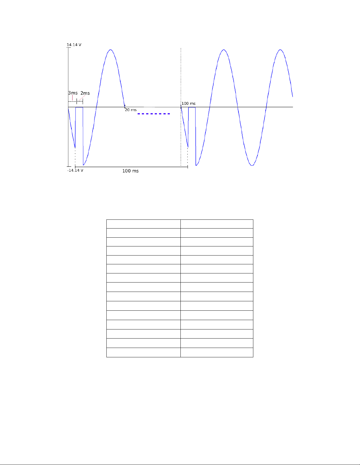
Power Line Disturbance Simulation (PLD)
In list mode, the user has the ability to enable or disable the disturbance simulator (PLD). If
enabled, an extended list of options will become available to easily simulate many different
power line disturbanc e conditions. Some of these waveforms include surge, sag, and dropout
waveforms. The following example shows a dropout waveform:
32
Page 47
Parameter
Input
Step Count
1
List Repeat
Any
Step 0 Voltage
10.0 V
Step 0 Frequency
50.0 Hz
Step 0 Slope
0.0 s
Dwell Units
Second
Step 0 Dwell
1
SD State
Enable
SD Continue
Yes
SD Step 0 Voltage
0.0 V
SD Step 0 Site
3.0 ms
SD Step 0 Time
2.0 ms
List Save
Yes
Save data bank
0
Figure 3.4 – Droput Waveform
To create the waveform above, access the list mode as described above and enter the following
parameters in the list mode file.
Once the list is saved to the desired memory bank, recall and run the program list by choosing
the correct memory location (please see the “Recall and Run Program” for further details).
33
Page 48

Note: If range is set to Auto and the swe e p pr ofile goes ov e r o r be low 150 V, there will be
delay is requir ed for the inst rum e n t to switch r a nges.
Voltage Sweep
Frequency Sweep
Voltage and Frequency Sweep
3.7 Sweep Mode
Sweep mode is used to create a sweep output with user-definable v o ltage and frequency
settings. The voltage and frequency settings may be selected by setting the initial voltage, final
voltage, step voltage, initial frequency, final frequency, step frequency and s t ep time. The step
time may be indicated in seconds, minutes or hours. Once the sweep starts, the power supply
will cycle through the voltage steps (from initial to final voltages) starting with the initial
frequency. Then the power supply will step to the next frequency and cycle through the
voltages steps (from initial to final voltages) again and repeat through all frequency steps until
the sweep is complete. The power supply can sweep up or down depending on configured start
and stop voltage and/or frequency. Once completed, the measured voltage, current, frequency,
and power factor when the maximum power output occurred during the sw e ep will be
displayed. The sweep function is ideal for testing the efficiency of switching power supplies or
capturing th e ope rating power requirements of the device under test. A maximum of 10 files
may be sto red.
a 50 ms delay during that inst a nce in which the instrument will output 0 V. This
Below are some examples of the type of sw e ep that can be setup and output fr om the power
supply.
There are two steps to set up a sweep output (in order):
1. Edit Sweep File
2. Recall and Run Program
The following sections will go into the details of setting up these steps.
34
Page 49

EnterEnter
Parameter
Operation Description
Input
Start Voltage
Sets the start voltage
0.0 V – 300.0 V
End Vol tage
Sets the end voltage
0.0 V – 300.0 V
Step Voltage
Sets the voltage step
0.1 V – 300.0 V
Time Unit
Sets the unit for the step time
Second, Minute, Hour
Step Time
Sets the step time
0.1 – 999.9
Start Frequency
Sets the start frequency
45.0 Hz – 500 Hz
End Frequency
Sets the end frequency
45.0 Hz – 500 Hz
Step Frequency
Sets the frequency step
0.1 Hz – 500 Hz
Yes, No
0-9)
EnterEnter
EnterEnter
Edit Sweep File
To access the edit list menu, press (Shift) and press “7” (“Sweep”). Now select the “Edit”
option and press
. The adjustable range and operation for each of the sweep
parameters are specified in table below:
Table 3.3 - Sweep Parameter Inputs
Sweep Save
Select Yes to sa ve the sweep to
memory bank 0-9
(If yes , select memory
Note: The sweep function will step through all of the voltage steps at the first frequency, then
step through the voltages for the next step frequency until the sweep is complete.
Recall and Run Sweep
Once the sweep file is configured and stored into memory, it can be recalled.
Recall Sweep
Follow the steps below to recall a stored sweep file from memory:
1. From the SWEEP menu (press (Shift) and press “7” (“Sweep”)), use the arrow keys to
select Recall and press
Recall Sweep = 0.
2. This is the location number where the program is stored in. Select a number between 0
to 9 with the rotary knob or the numeric keypad, then press
3. Once selected, the display will read “Recall Data Success” and will return back to the
SWEEP menu.
. The display will say RECALL SWEEP with th e pr ompt
.
35
Page 50

EnterEnter
On/Off
EnterEnter
EnterEnter
On/Off
On/Off
On/Off
300.0V
0.0mA
0.00W
OFF
PF = 0.000
500
Sweep
150.0V
0.0mA
0.00W
OFF
PF = 0.000
60
Lock
Run Sweep
Follow the steps below to run the recalled sweep file:
1. Assuming the stored sweep has already been recalled, from the SWEEP menu, with
Disable selected, press the up or down key to select Enable and press
Sweep text will appear below the frequency of the display, as shown below:
2. Press the
key will begin to blink while the sweep is running.
3. When the sweep ends, the
automatically.
key to enable (ON) the output and allow the sweep to run. The
will stop blinking and the output will s hut off
. The
3.8 Key Lock
The front panel keys can be locked to prevent unwanted changes to output settings and power
supply configurations. Follow the steps below to enable/disable key lock.
1. Press (Shift) and (Lock)
the front panel keys are locked.
2. All keys are now disabled except for (Shift) ,
and (to change display readback).
. The follow display will be shown, indicating that
(Lock function and output state),
3. To unlock the keys again, press (Shift) and
disappear and all keys will be enabled.
again. The “Lock” indicator will
36
Page 51

PIN
Description
1 - 2
TXD, Transmit Da t a
3
RXD, Receive Data
4
-
5
GND 6 -
7
CTS, clear transfer
8
RTS, ready to transfer
9
-
1 2 3 4 5
6
7 8 9
4 Remote Operation
4.1 Interface Connection
RS-232
For RS-232 connectivity, refer to th e diag ram below for pin out information. The RS-232 is
labeled in the rear panel and it is a female DB-9 interfac e. To select this interface t o
communicate with the unit, please see Communication Setup.
A straight pin-to-pin DB9 female to DB9 male serial cable is required for using the RS-232
interface. Do not use a null modem or crossover DB9 serial cable.
USBTMC
The instrument has a USB interface (USBTMC) on the rear panel for remote communication. To
select this interface to communicate with the unit, please see Communication Setup.
LAN
The LAN interface uses an Ethernet (RJ-45) connec ti on o n th e rear pane l a nd supports a socket
connection. To select this interface to communicate with the unit, please see Communication
Setup.
37
Page 52

4.2 Remote Commands
The instrument supports some SCPI commands and some instrument specific commands. These
commands enable a computer to remotely communicate and control the power supply over any
of the supported remote interfaces: USBTMC, RS-232, and LAN.
Refer to the pr ogramming manual for details, whi ch can be downloa d ed from
www.bkprecision.com.
38
Page 53

5 Troubleshooting Guide
Below are some frequently asked questions and answers. Please check if any apply to your
power supply before contacting B&K Precision.
General
Q: I cannot power up the power supply.
- Check that the power cord is securely connected to the AC input and there is live power
from your electrical AC outlet.
- Verify that the AC power coming from the mains have the correct voltage. The power
supply can accept a specific range of AC input voltages. Refer to section “2.1”.
Q: How come my display voltage is lower than the voltage I set?
- This is often because of the resistances from the test leads/wires connected between the
supply and the DUT (device under test), which causes a drop in voltage. To minimize this
drop, use remote sense terminals to compensate and output a more accurate voltage to
the DUT.
Q: Why can’t I set voltage and/or frequency under or over a specific limit?
- This may be that the se t v ol ta g e a nd / or frequency is outside of the set limits in the menu
settings. Refer to the voltage limits section under “Voltage Limits” or frequency limits
under “Frequency Limits” to verify and configure these limits.
Q: Why does my output waveform look cut off and distorted on my oscilloscope?
- Check to see if the dimmer function is enabled. If it is, it is likely the r es ul t o f the phase
being cut, which results in a distorted waveform. This also leads to less RMS voltage. See
the Dimmer section for more information.
Remote Control
Q: I am trying to send the commands over USB/RS232, but it does not seem to respond.
- Check that you are sending ASCII strings that are terminated with a CR (carriage return)
and LF (linefeed) character.
- For RS-232, check that the baudrate, parity, data bits, stop bit, and flow control settings
match with the settings configured on the software interface.
- Check that pins 2 and 3 are not crossed.
39
Page 54

Model
9801
AC Input
Phase
Single
Voltage
110 / 220 VAC ± 10%
Frequency
47 – 63 Hz
Current
8 A max.
Power Factor
0.5 (typical)
AC Output
Max. Power
300 VA
(RMS)
0 – 150 V
3 A
0 – 300 V
1.5 A
Max Current
(Peak)
0 – 150 V
12 A
0 – 300 V
6 A
Phase
Single
Crest Factor
≥ 4
Total Harmonic Distortion (T. H.D)
≤ 0.5% at 45 – 500 Hz (Resistive Load)
Line Regulation
0.1 % max for a ± 10% line change
Load Regulation
≤ 0.5% FS (Resistive Load)
Response Time
< 100 μs
Programming
Range
0 – 300 V, 150 / 300 V (Auto)
Resolution
0.1 V
Accuracy
± (0.2% + 0.6 V)
Range
45 – 500 Hz
0.1 Hz at 45 – 99.9 Hz
1 Hz at 100 – 500 Hz
Accuracy
0.1 Hz
Range
0 – 360 °
Resolution
0.1 °
Accuracy
± 1° (45 – 65 Hz)
Readback
Range
0 – 300 V
Resolution
0.1 V
Accuracy
± (0.2% + 0.6 V)
Range*
Low: 120.0 mA / Mid: 1.200 A / High: 3.00 A
Resolution
Low: 0.1 mA / Mid: 1 mA / High: 10 mA
Accuracy
Low: ± (0.2% + 0.4 mA) / Mid: ± (0.2% + 4 mA) / High: ± (0.2% + 20 m A )
Range
0 – 12 A
Resolution
0.01 A
Accuracy
± (1% + 120 mA)
Resolution
Low: 0.01 W / Mid: 0.1 W / High: 1 W
Accuracy
Low: ± (0.2% + 0.05 W) / Mid: ± (0.2% + 0.5 W) / High: ± (0.2% + 2 W )
6 Specifications
Note: All specifications apply to the unit after a temperature stabilization time of 15 minutes over an ambient
temperature range of 23 °C ± 5 °C. Specifications are subject to change without notice.
Max Current
Voltage
Frequency
Phase Angle
Voltage
Current
(RMS)
Current
(peak)
Power
Resolution
40
Page 55

(47 – 65 Hz)
General
Memory
10 locations
External BNC, input/output
Trigger input, sync output, output status, output indicator/control
Interface
LAN, USB, RS232
Operating Environment
0 – 40 °C, 20 – 80% RH
Dimensions (W×H×D) (mm)
214.5 × 88.2 × 453.5
Weight
9.5 kg
* The current range switches from low to mid range or mid to high range when Ipeak > 300 % of the present range.
When Ipeak is <80 % of the high range, the current range switches from high to mid range.
When Ipeak is <20 % of the mid range, the current range switches from mid to low range.
To ensure the most current version of this manual, please download the latest version here:
http://www.bkprecision.com/search/9801
For current up-to-date product information, please visit www.bkprecision.com
Calibration
We recommend a calibration interval of once per year to ensure that the power supply meets
specifications.
41
Page 56

SERVICE INFORMATION
Warranty Service: Please go to the support and service section on our website at www.bkprecision.com to obtain a RMA #.
Return the product in the original packaging with proof of purchase to the address below. Clearly state on the RMA the
performance problem and return any leads, probes, connectors and accessories that you are using with the device.
Non-Warranty Service: Please go to the support and service section on our website at www.bkprecision.com to obtai n a RMA
#. Return the product in the original packaging to the address below. Clearly state on the RMA the performance problem and
return any leads, probes, connectors and accessories that you are using with the device. Customers not on an open account
must include payment in the form of a money order or credit card. For the most current repair cha rges please refer to the
service and support section on our website.
Return all merchandise to B&K Precision Corp. with prepaid shipping. The flat-rate repair charge for Non-Warranty Service does
not include return shipping. Return shipping to locations in North Amer ica is included for Warranty Service. For overnight
shipments and non-North American shipping fees please contact B&K Precision Corp.
B&K Precision Corp.
22820 Savi Ranch Parkway
Yorba Linda, CA 92887
www.bkprecision.com
714-921-9095
Include with the returned instrument your complete return shipping address, contact name, phone number and description
of problem.
Page 57

LIMITED THREE-YEAR WARRANTY
B&K Precision Corp. warrants to the or iginal purchaser that its products and the component parts thereof, will be free from
defects in workmanship and materials for a period of three years from date of purchase.
B&K Precision Corp. w ill, without charge, repair or replace, at its option, defective product or component parts. Returned
product must be accompanied by proof of the purchase date in the form of a sales receipt.
To help us better serve you, please complete the warranty registration for your new instrument via our website
www.bkprecision.com
Exclusions: This warranty does not apply in the event of misuse or abuse of the product or as a result of unauthorized
alterations or repairs. The warranty is void if the serial number is altered, defaced or removed.
B&K Precision Corp. shall not be liable for any consequential damages, including without limitation damages resulting from loss
of use. Some states do not allow limitations of incidental or consequential damages. So the above limitation or exclusion may
not apply to you.
This warranty gives you specific rights and you may have other rights, which vary from state-to-state.
B&K Precision Corp.
22820 Savi Ranch Parkway
Yorba Linda, CA 92887
www.bkprecision.com
714-921-9095
Page 58

22820 Savi Ranch Parkway
Yorba Linda, CA 92887
www.bkprecision.com
© 2015 B&K Precision Corp.
Printed in China v040215
 Loading...