

Page 1

Model: 9171, 9172, 9173, 9174, 9181, 9182,
9183, 9184, 9185
Programmable DC Power
Supplies
USER MANUAL
Page 2

Page 3

Safety Summary
The following safety precautions apply to both operating and
maintenance personnel and must be observed during all phases of
operation, service, and repair of this instrument. Before applying
power, follow the installation instructions and become familiar with
the operating instructions for this instrument.
If this device is damaged or something is missing, contact the place
of purchase immediately.
This manual contains information and warnings that must be
followed to ensure safe operation as well as maintain the meter in
a safe condition.
GROUND THE INSTRUMENT
To minimize shock hazard, the instrument chassis and cabinet
must be connected to an electrical ground. This instrument is
grounded through the ground conductor of the supplied, three-
conductor ac power cable. The power cable must be plugged into
an approved three-conductor electrical outlet. Do not alter the
ground connection. Without the protective ground connection, all
accessible conductive parts (including control knobs) can render an
electric shock. The power jack and mating plug of the power cable
must meet IEC safety standards.
DO NOT OPERATE IN AN EXPLOSIVE ATMOSPHERE
Do not operate the instrument in the presence of flammable gases
or fumes. Operation of any electrical instrument in such an
environment constitutes a definite safety hazard.
Page 4

KEEP AWAY FROM LIVE CIRCUITS
Instrument covers must not be removed by operating personnel.
Component replacement and internal adjustments must be made
by qualified maintenance personnel. Disconnect the power cord
before removing the instrument covers and replacing components.
Under certain conditions, even with the power cable removed,
dangerous voltages may exist. To avoid injuries, always
disconnect power and discharge circuits before touching them.
DO NOT SERVICE OR ADJUST ALONE
Do not attempt any internal service or adjustment unless another
person, capable of rendering first aid and resuscitation, is present.
DO NOT SUBSTITUTE PARTS OR MODIFY THE INSTRUMENT
Do not install substitute parts or perform any unauthorized
modifications to this instrument. Return the instrument to B&K
Precision for service and repair to ensure that safety features are
maintained.
WARNINGS AND CAUTIONS
WARNING and CAUTION statements, such as the following
examples, denote a hazard and appear throughout this manual.
Follow all instructions contained in these statements.
A WARNING statement calls attention to an operating procedure,
practice, or condition, which, if not followed correctly, could result in
injury or death to personnel.
Page 5

Do not alter the ground connection. Without the protective
ground connection, all accessible conductive parts (including
control knobs) can render an electric shock. The power jack and
mating plug of the power cable meet IEC safety standards.
To avoid electrical shock hazard, disconnect power cord before
removing covers. Refer servicing to qualified personnel.
Before connecting the line cord to the AC mains, check the rear
panel AC line voltage indicator. Applying a line voltage other than
the indicated voltage can destroy the AC line fuses. For
continued fire protection, replace fuses only with those of the
specified voltage and
This product uses components which can be damaged by electrostatic discharge (ESD). To avoid damage, be sure to follow proper
procedures for handling, storing and transporting parts and
subassemblies which contain ESD
A CAUTION statement calls attention to an operating procedure,
practice, or condition, which, if not followed correctly, could result in
damage to or destruction of part or all of the product.
WARNING:
WARNING:
CAUTION:
CAUTION:
current ratings.
-sensitive components.
Page 6
This product is subject to Directive
Compliance Statements
Disposal of Old Electrical & Electronic Equipment (Applicable
in the European
Union and other European countries with separate collection
systems)
2002/96/EC of the European
Parliament and the Council of the
European Union on waste
electrical and electronic equipment
(WEEE) , and in jurisdictions
adopting that Directive, is marked
as being put on the market after
August 13, 2005, and should not be
disposed of as unsorted
municipal waste. Please utilize your
local WEEE collection
facilities in the disposition of this
product and otherwise observe all
applicable requirements.
Page 7

CE Declaration of Conformity
The power supplies models 9171, 9172, 9173, 9174, 9181, 9182,
9183, 9184, 9185 meet the requirements of 2006/95/EC Low
Voltage Directive and 2004/108/EC Electromagnet Compatibility
Directive with the following standards.
Low Voltage Directive
- EN61010-1: 2001
Safety requirements for electrical equipment for
measurement, control, and laboratory use.
Part 1: General requirements
EMC Directive
- EN 61000-3-2: 2006
- EN 61000-3-3: 1995+A1: 2001+A2: 2005
- EN 61000-4-2: 1995+A1: 1998+A2: 2001
- EN61000-4-3: 2006+A1: 2008
- EN61000-4-4: 2004
- EN61000-4-5: 2006
- EN61000-4-6: 2007
- EN61000-4-11: 2004
- EN 61326-1: 2006
Electrical equipment for measurement, control,
and laboratory use.
Page 8
instrument.
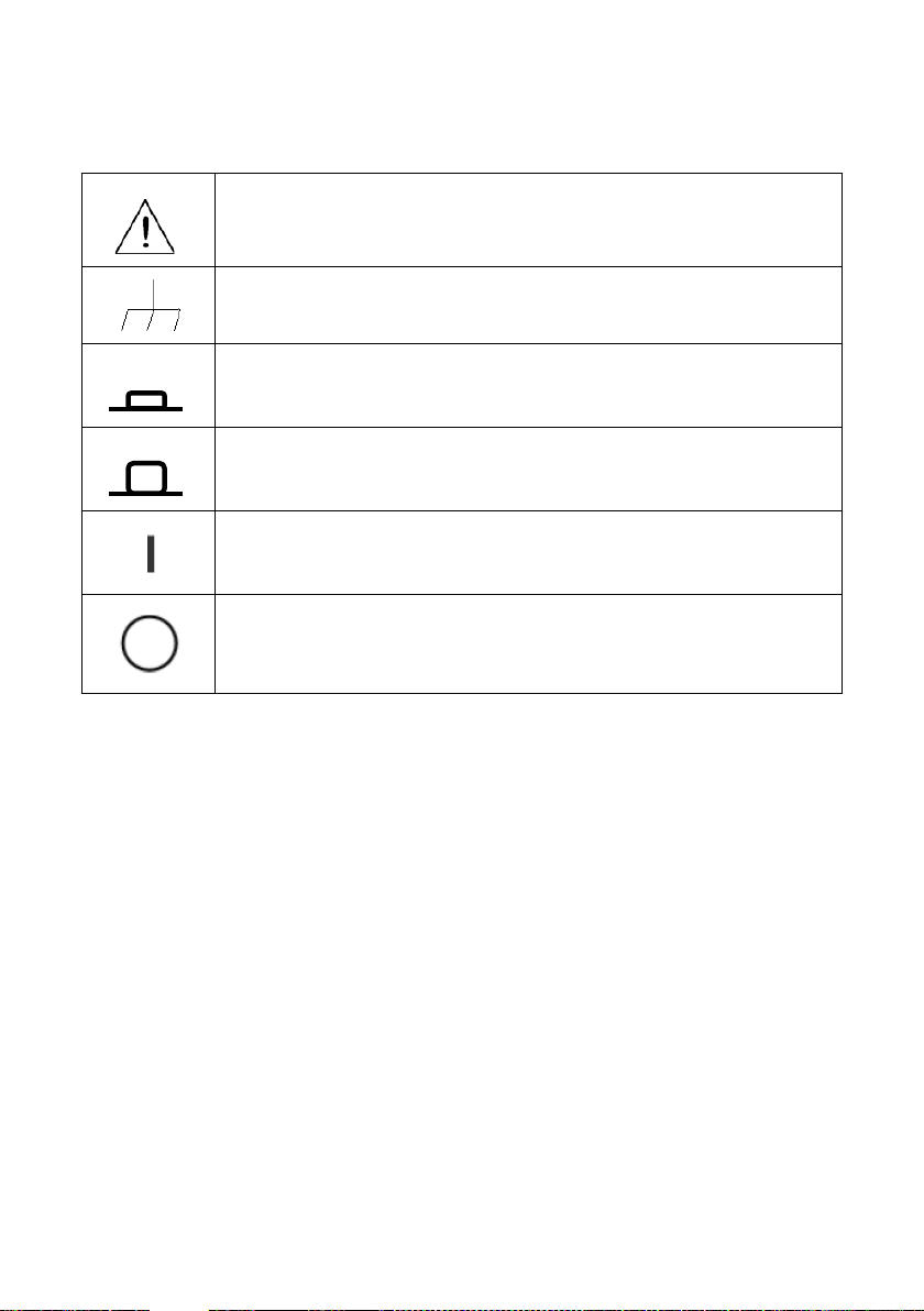
Safety Symbols
Refer to the user manual for warning information to
avoid hazard or personal injury and prevent damage to
Chassis (earth ground) symbol.
On (Power). This is the In position of the power switch
when instrument is ON.
Off (Power). This is the Out position of the power switch
when instrument is OFF.
On (Supply). This is the AC mains connect/disconnect
switch at the back of the instrument.
Off (Supply). This is the AC mains connect/disconnect
switch at the back of the instrument.
Page 9

Table of Contents
1 General Information ........................................................... 1
1.1 Product Overview ................................................................ 1
1.2 Package Contents ................................................................. 2
1.3 Front Panel Overview........................................................... 3
Front Panel Description ................................................................. 5
1.4 Rear Panel Overview ............................................................ 6
Rear Panel Description .................................................................. 8
1.5 Optional Accessories ............................................................ 8
Interface Card Options .................................................................. 8
Rack mount Options...................................................................... 9
1.6 Display Overview ................................................................. 9
Display Description ..................................................................... 10
1.7 Installing Optional Interface Cards .................................... 10
How to Install Interface Cards ..................................................... 11
Removing Interface Cards ........................................................... 12
1.8 Rackmount Installation ...................................................... 13
2 Getting Started .................................................................... 18
2.1 Input Power and Fuse Requirements ................................ 18
Input Power ................................................................................. 18
Fuse Requirements ...................................................................... 18
2.2 Line Voltage Selection ........................................................ 19
2.3 Output Connections ........................................................... 21
2.4 Preliminary Check .............................................................. 23
Output Check .............................................................................. 25
Check Model and Firmware Version ........................................... 27
3 Front Panel Operation ...................................................... 28
Page 10

3.1 Menu Options .................................................................... 28
How to Access the Menu ............................................................. 29
3.2 Remote Interface Setup ..................................................... 32
USB Interface (virtual COM) ........................................................ 32
GPIB Interface ............................................................................. 34
Ethernet (LAN) Interface ............................................................. 34
RS-232 and RS-485 Interface (Optional) ..................................... 35
3.3 Adjusting LCD Display, Key Lock, Key Sound ...................... 39
LCD Backlight Timer .................................................................... 39
Key Lock ...................................................................................... 39
Disabling Key Sound .................................................................... 40
3.4 Restore to Factory Default ................................................. 41
3.5 Configure Voltage and Current Output .............................. 43
Voltage and Current Limit Settings ............................................. 43
Configure Voltage and Current Output ....................................... 45
Slew Rate Configuration ............................................................. 51
Output Timer Function ................................................................ 53
Measurement Average Setting ................................................... 55
3.6 Dual Channel Configurations ............................................. 55
Multi/Single Output Control ....................................................... 55
Series/Parallel Tracking Mode .................................................... 56
3.7 Remote Sense .................................................................... 57
3.8 LED and Low Current Test Modes ...................................... 62
LED Mode .................................................................................... 62
Low Current Mode ...................................................................... 64
3.9 Output Protection .............................................................. 66
Configure OVP ............................................................................. 66
Configure OCP ............................................................................. 67
Page 11

3.10 Save/Recall Output Settings .............................................. 68
3.11 Sequence Program Mode .................................................. 71
3.12 External Analog Control ..................................................... 72
3.13 Digital I/O ........................................................................... 77
INPUT .......................................................................................... 79
OUTPUT ...................................................................................... 80
3.14 Display Errors ..................................................................... 81
3.15 Connecting in Series and Parallel ....................................... 82
4 Remote Operation .............................................................. 83
4.1 Interface Connection ......................................................... 83
USB (Virtual COM) & RS-232 ....................................................... 83
GPIB ............................................................................................ 84
Ethernet (LAN) ............................................................................ 85
4.2 Remote Commands ........................................................... 90
Parameter Definitions ................................................................. 91
Remote Commands ..................................................................... 91
4.3 Sequence Programming ................................................... 134
Examples ................................................................................... 134
4.4 Multi Unit Programming .................................................. 138
Remote Commands via USB ...................................................... 139
5 Troubleshooting Guide ................................................. 150
General ..................................................................................... 150
Remote Control ......................................................................... 152
6 Specifications ................................................................... 153
7 Calibration ......................................................................... 158
Access Calibration Menu ........................................................... 158
Requirements ............................................................................ 159
Current Calibration ................................................................... 159
Page 12

Voltage Calibration ................................................................... 163
External Analog Input Calibration............................................. 165
Index ........................................................................................... 170
SERVICE INFORMATION ........................................................ 171
LIMITED THREE-YEAR WARRANTY ................................. 172
Page 13

1 General Information
1.1 Product Overview
The 917x and 918x series are high-performance dual range linear
DC power supplies that provide clean and reliable power with high
resolution and accuracy. All models are programmable via standard
USB interface or optional RS232, GPIB and LAN interface.
Interface cards and I/O cards come in a modular form factor.
Selected models feature high voltage outputs or dual channels to
provide series/parallel tracking functionality. All models include front
and rear panel outputs for flexibility, and feature programmable list
mode for storing and running customized test sequences.
Additionally, a unique LED test mode function can be enabled for
LED test applications requiring minimal inrush current output. These
power supplies are suitable for bench or rack mount operation with
the available rack mount kit option.
Features
• Single and dual output models with up to 210W output power
• High accuracy and low noise output
• Dual range output with automatic range selection (except of
high voltage models 9184 and 9185)
• Fast transient response of < 50 μs of most models
• Very low ripple and noise
• LED test mode for low inrush current output
• Programmable list mode for creating test sequences
• Front and rear remote sense terminals for single output
models (except of high voltage models 9184 and 9185)
• OVP, OCP, and OTP protection
• Two interchangeable interface slots accepting any of the
following optional interface cards: LAN/GPIB, Digital I/O and
Analog control, RS485, RS232
• Standard USB interface (virtual COM)
• Programmable voltage and current slew rates
1
Page 14

1.2 Package Contents
Please inspect the instrument mechanically and electrically upon
receiving it. Unpack all items from the shipping carton, and check for
any obvious signs of physical damage that may have occurred
during transportation. Report any damage to the shipping agent
immediately. Save the original packing carton for possible future
reshipment. Every power supply is shipped with the following
contents:
• 917x/918x Power supply
• User Manual
• AC Power Cord
• USB Type A to Type B Cable
• Line fuse (for 115V or 230V operation)
• Certificate of Calibration
• Test Report
Verify that all items above are included in the shipping container. If
anything is missing, please contact B&K Precision.
2
Page 15
19
1
2 5 6
16
2120 18
17
10 11 8 12 13
14
3 4 97
15
1
19
2 517106 7 11 8 129 133 4
16
14
15
18
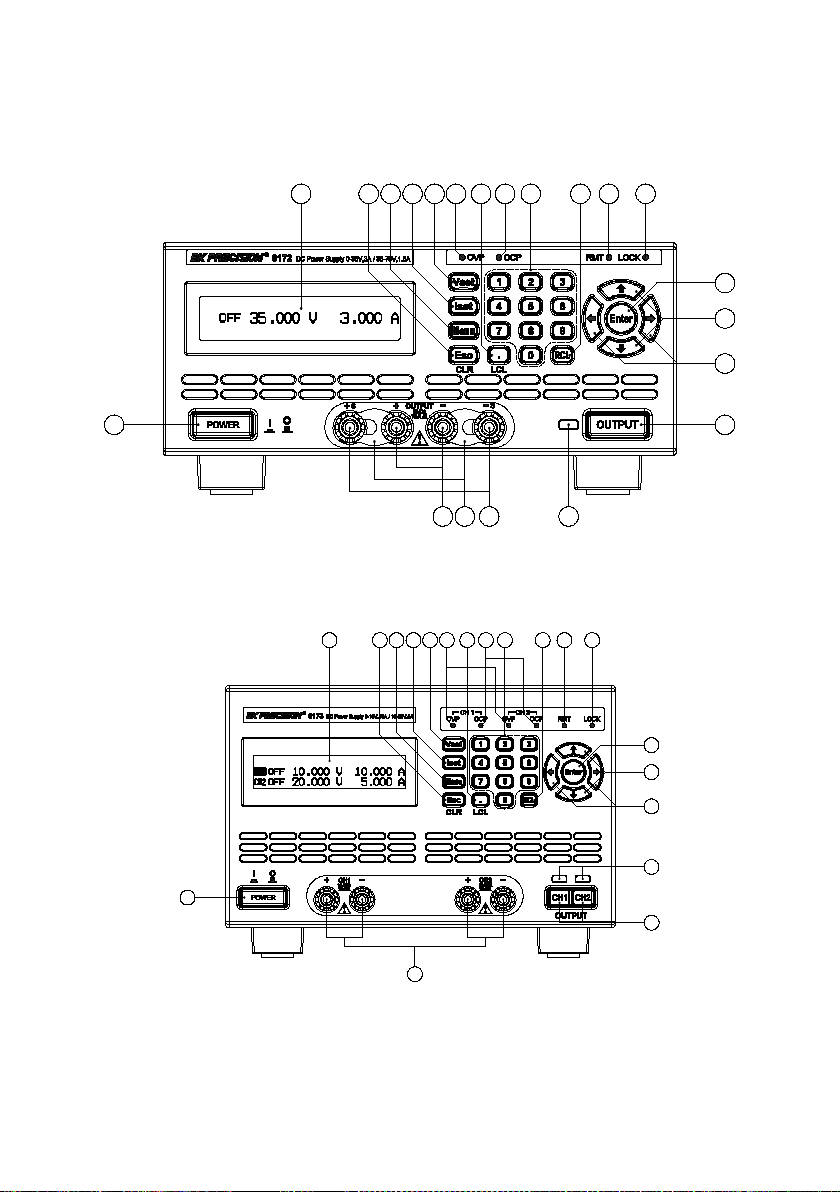
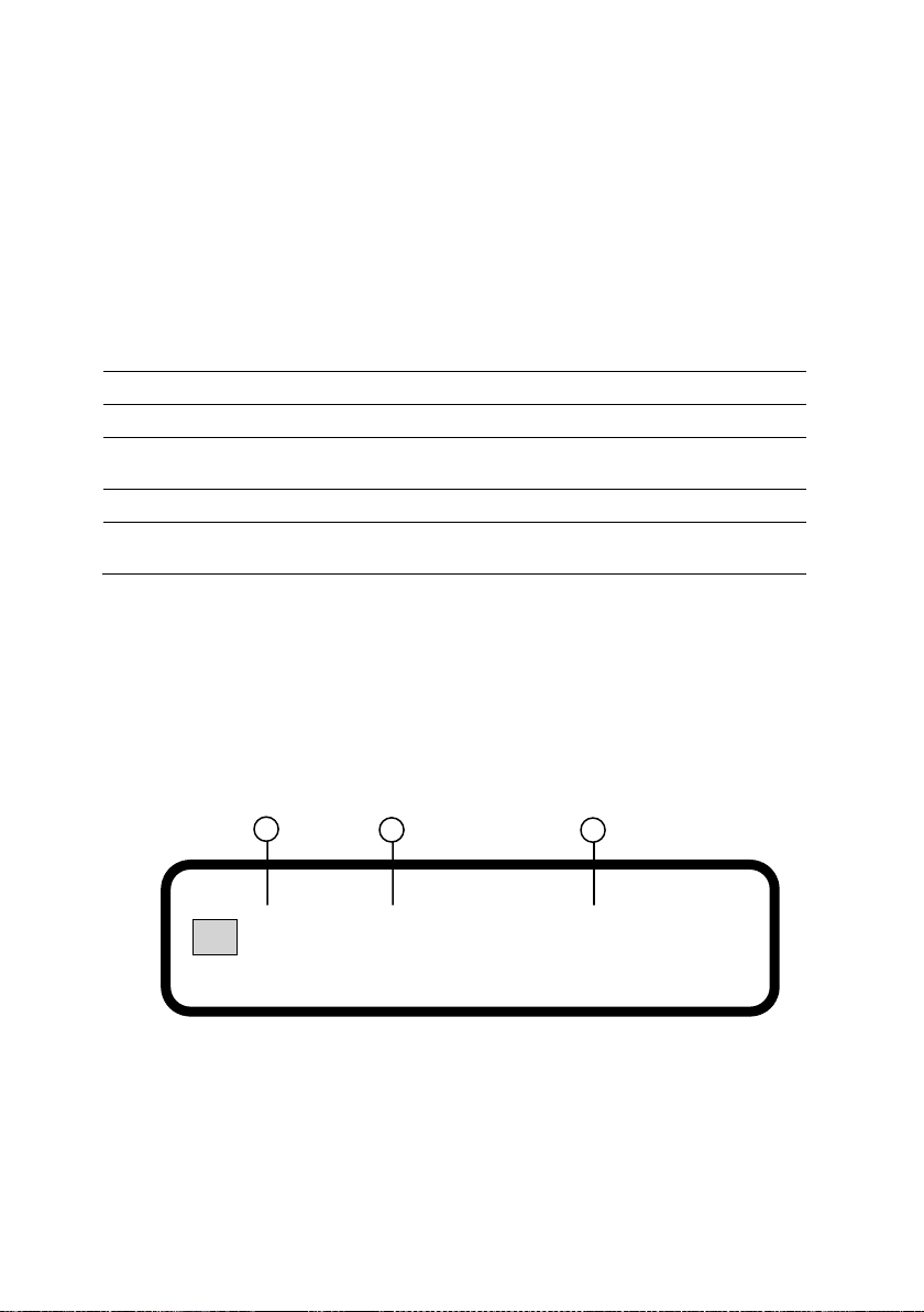
1.3 Front Panel Overview
Figure 1 - Front Panel for 9171/9172/9181
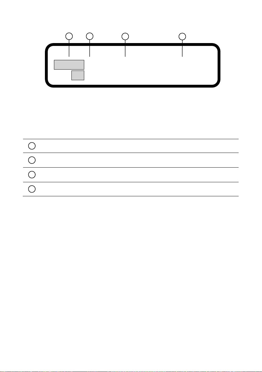
Figure 2 - Front Panel for 9173/9174
3
Page 16
1
2 5
17
10
6
7 11
8 12
9
13
3
4
16
14
15
18
20
19 21
1
2 517106 7 11 8 129 133 4
16
14
15
18
19
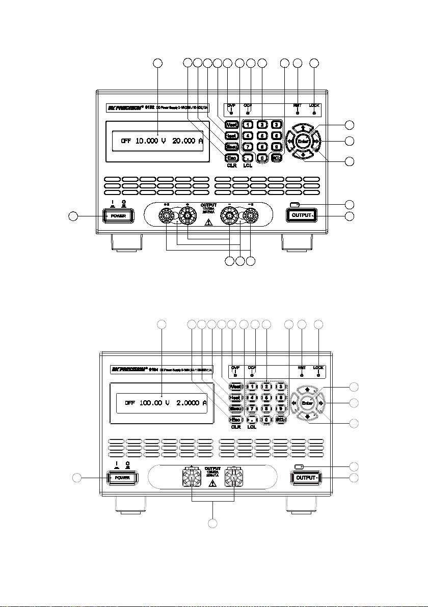
Figure 3 - Front Panel for 9182/9183
4
Figure 4 - Front Panel for 9184/9185
Page 17
Output button (Dual channel models have CH1 and CH2 output
buttons)
Main output terminals (Models 9182,9184,9185 have larger binding
post terminals for high current/voltage outputs)
Front panel +S/-S sense terminals (Not available with models 9173,
9174, 9184, 9185)
1 2 3
4
5 6 7
8
9
10
11
14
15
16
17
18
19
20
21
12
13
Front Panel Description
Power ON/OFF button
LCD display
Esc / CLR button
Menu button
ISET button
VSET button
Decimal/LCL(Local) button
Numeric keypad
RCL (Recall) button
OVP indicator
OCP indicator
RMT (Remote mode) indicator
LOCK (Key lock) indicator
Enter button
Up, Down arrow keys
Left, Right arrow keys
Output ON/OFF indicator light
Front terminal shorting bars
5
Page 18
22
23
24
31
29
30
28
25 26 27
29
28
22
25
24
23
30
29
28
31
25
26 27
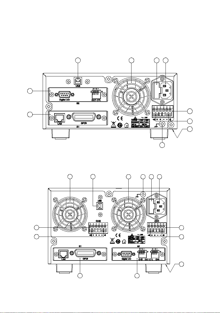
1.4 Rear Panel Overview
Figure 5- Rear View for 9171/9172/9181
Figure 6- Rear View for 9173/9174
6
Page 19
29
28
22
25 24
23
30
3125 26 27
29
28
22 23
30
3124 26 27
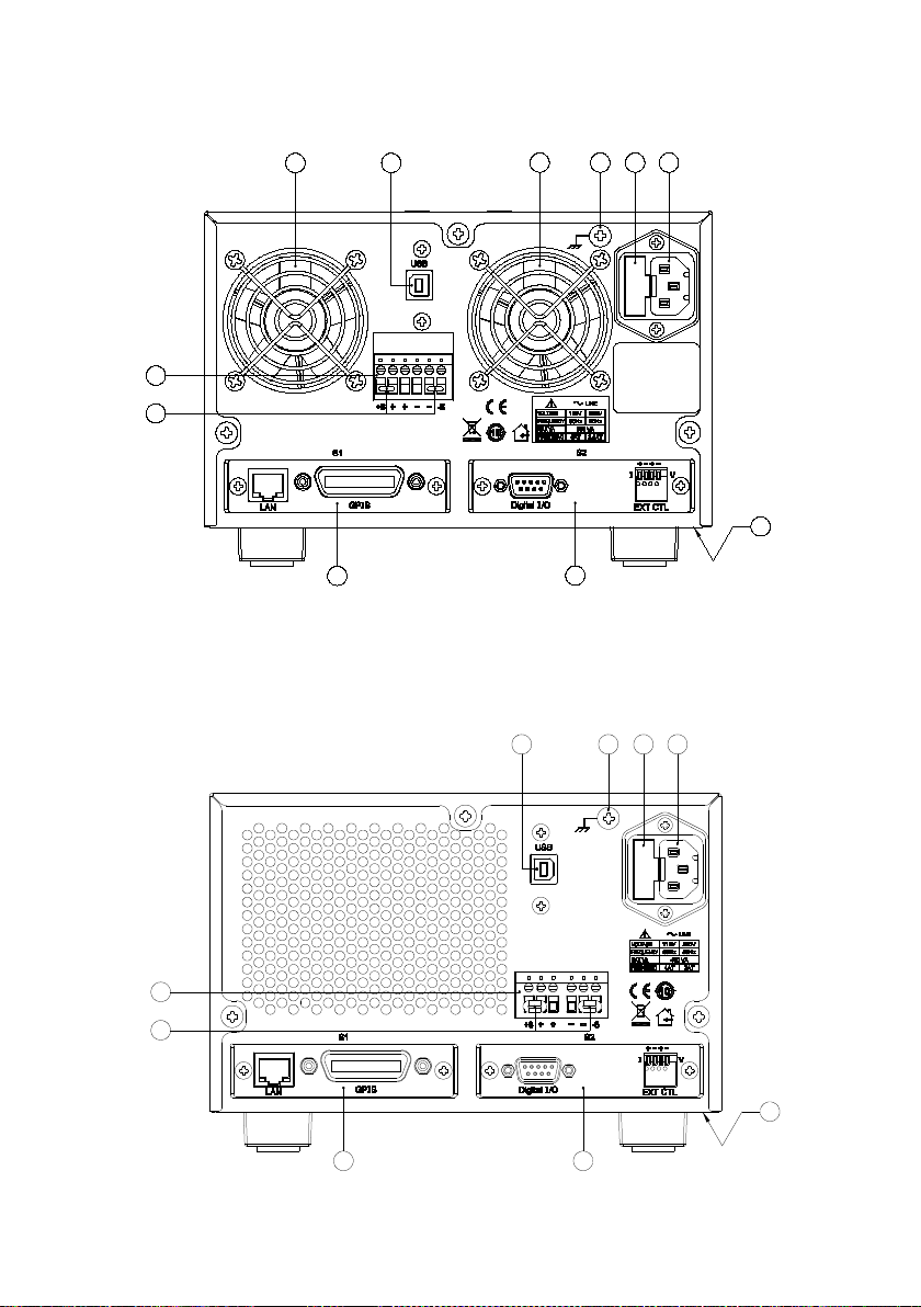
Figure 7- Rear View for 9182/9183
Figure 8- Rear View for 9184/9185
7
Line voltage selection switch (bottom of power supply) See “2.2Line
Voltage Selection” for details.
Page 20
Model
Description
DRGL
GPIB/LAN interface card
DR1DIO
Single channel digital I/O and analog control card
DR2DIO
Dual channel digital I/O and analog control card
DRRS485
RS485 interface card
DRRS232
RS232 interface card
24
25
26
27
28
29
30
31
22
23
Rear Panel Description
S1 interface slot (shown with optional LAN/GPIB interface card)
S2 interface slot (shown with optional DIO/Analog interface card)
USB interface
Temperature controlled cooling fan(s)
AC input fuse box
Line input receptacle
Rear panel outputs (++/--) and sense (+S/-S) terminals
Shorting pins
Chassis ground
1.5 Optional Accessories
The following lists all optional accessories supported by the
917x/918x series power supplies.
Interface Card Options
8
Page 21
Model
Description
Rackmount kit for two 2U power supplies mounted
side by side
DRRM3U1
Rackmount kit for single 3U power supply
Rackmount kit for two l 3U power supplies mounted
side by side
2 3 1
Rack mount Options
Rackmount kits are available for all 9 models. Refer to the following
to determine your power supply rack mount size.
2U size: Models 9171, 9172, 9181
3U size: Models 9173, 9174, 9182, 9183, 9184, 9185
DRRM2U1 Rackmount kit for single 2U power supply
DRRM2U2
DRRM3U2
1.6 Display Overview
The main displays for single and dual channel models are shown
below.
CV5 . 000 V1 . 000 A
Figure 9- Main Display
9
Voltage display (When output is OFF, it shows VSET voltage. When
output is ON, it shows measured voltage)
Page 22
Current display (When output is OFF, it shows ISET current. When
output is ON, it shows measured current)
CH2CV5 . 000 V1 . 000 A
2 3 1
4
1
2
3
4
CH1CV5 . 000 V1 . 000 A
Figure 10- Dual Channel Main Display
Display Description
Output Mode (CV, CC, OFF)
Selected channel indicators
1.7 Installing Optional Interface Cards
Five optional interface cards are available and can be installed in
either the S1 or S2 slots. They are:
Option 1: GPIB/LAN Card
Adds GPIB and LAN interface
Option2: DIO/Analog Card (Single channel)
Adds digital I/O and External Analog Control
Option 3: DIO/Analog Card (Dual channel)
Adds dual channel digital I/O and External Analog Control
Option 4: RS485 Card
10
Page 23
S1
: : : : : : : : : : : : : : : : : : : : : :
Metal
notch
Card
rail
48-pin female connector
S1
Adds RS-485 interface for multi power supply control
Option 5: RS232 Card
Adds RS-232 interface
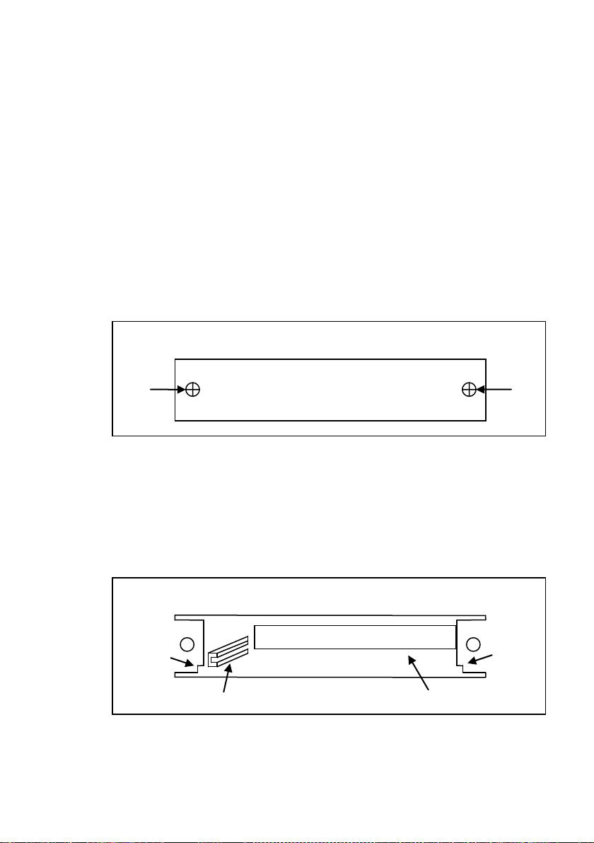
How to Install Interface Cards
1. Power off the instrument and disconnect the AC power cord
in the rear panel. Remove the back faceplate covering the
S1 or S2 slot in the rear panel by removing the two screws
on each side.
2. Make note of the metal notches that indicate where the card
should slide into. Inside the slot, there are two rails (left and
right side) where the card should slide smoothly into. The
very back of the slot is a 48-pin female connector that should
connect with the 48-pins on the back of the interface card.
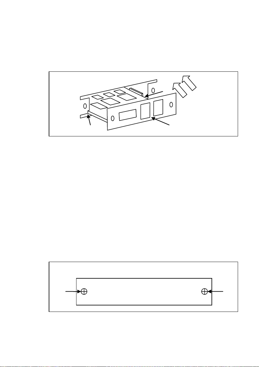
3. The interface card should go right below the metal notches
on both sides and fit in between the inner card rails, also on
11
Page 24
S1
Interface card
both sides. Slide the card down carefully. When it touches
the 48-pin connector, slowly push the card all the way in until
the panel of the interface card aligns with the rear panel of
the power supply.
4. Place the two screws to tighten and secure the installed card.
5. Connect the power cord and turn on the power supply. The
newly installed card will be detected during boot up, indicated
next to S1: or S2: (depending on which slot the card is
installed into).
Removing Interface Cards
1. Power off the instrument and disconnect the AC power cord
2. Use a flat blade screwdriver to gently pry the left and right
in the rear panel. Remove the two screws on each side of
the installed interface card.
side of the interface card plate. When there is enough room,
12
Page 25

use the screwdriver to pry the top part of the card until the
card has slid out with enough room to pull out the card by
hand.
3. Be sure to ground yourself before pulling out or touching any
parts of the printed board on the interface card.
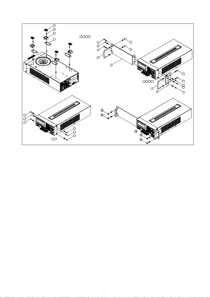
1.8 Rackmount Installation
There are four rackmount kit options available for this series of
power supplies: 2U size for single power supply, 2U size for two
power supplies mounted side by side, 3U size for single power
supply, 3U size for two power supplies mounted side by side. The
following step by step instructions will guide you in installing these
optional rackmount kits onto the power supply for a standard 19-inch
rack fitting.
Models 9171, 9172, 9181: Follow instructions for 2U rackmount
installation.
Models 9173, 9174, 9182, 9183, 9184, 9185: Follow instructions for
3U rackmount installation.
13
Page 26
5
R
emo
ve t
he p
arts
S
tep
2:
5
6
5
6
6
5
5
Step 2
Step 1
7
5
5
1
1
Re
m
ov
e t
h
e p
ar
t
s
S
te
p 1
:
4
2
3
2 3 4
5
Step 4
Fas
ten
the
par
ts
S
tep
4:
7
9
5
5
5
Step 3
Fas
ten
the p
art
s
S
tep
3:
8
5
5
7 9
8
5
5
5
Figure 11- 2U Single Supply Rackmount Installation
14
Page 27
Step 1
Step 1:
3
1
2
Remov e the parts
4
21 3 4
6
9
6
7
Step 3
7
Step 3:
Removethe parts
Step 5
7
Fasten the parts
6
6
6
Step 2:
5
6
65
Step 2
Step 4
8
Fasten the parts
Step 4:
7
7
7
8
Fasten the parts
Remov e the parts
Step 5:
Step 7:
Step 7
6
9
6
6
6
9
6
6
Step 6
6
6
Step 6:
Fasten the parts
6
6
6
6
6
6
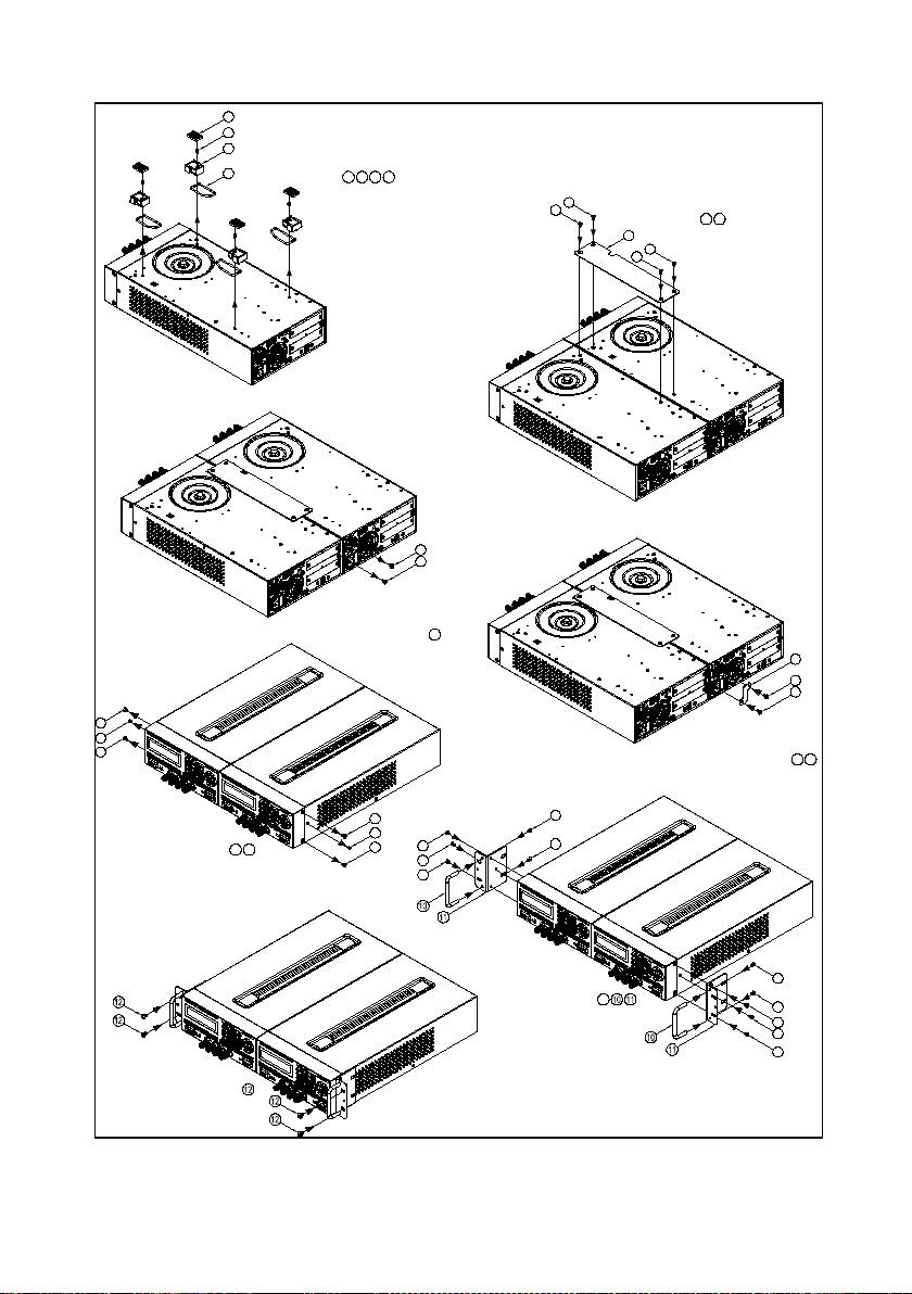
Figure 12- 2U Dual Supplies Rackmount Installation
15
Page 28
Rem ove t he par ts
Step 2:
5
5
6
65
5
5
6
Step 2
5
Step 1
7
5
Rem ove t he par ts
2
3
4
Step 1:
1
21 43
5
Fas ten th e par ts
Ste p 4:
7
Step 4
9 5
5
5
Step 3
Fas te
n t
h
e p
art s
8
Step 3
:
5
97 8
5
5
5
5
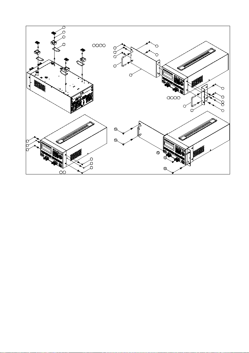
Figure 13- 3U Single Supply Rackmount Installation
16
Page 29
Step 1
3
Step 1:
1
2
Remove the parts
4
21 43
6
9
6
Step 3
Step 3:
Removethe parts
Step 5
7
7
7
Step 2
Step 2:
Fasten the parts
6
6
5
6
6
5
6
Step 4:
Fasten the parts
Step 4
8
8
7
7
7
Fasten the parts
Removethe parts
Step 5:
Step 7:
Step 7
96
6
6
9
6
6
6
Step 6
Step 6:
6
6
Fasten the parts
6
6
6
6
6
6
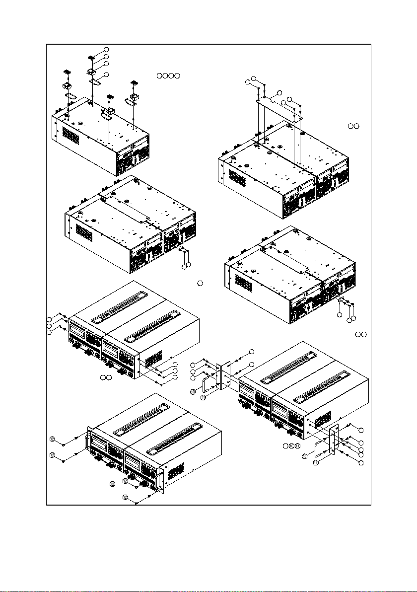
Figure 14–3U Dual Supplies Rackmount Installation
17
Page 30

2 Getting Started
2.1 Input Power and Fuse Requirements
Input Power
The rated AC input power source for powering the supplies must be
within:
115V Operation:103.5V-126.5V
230V Operation: 207V - 253V
Frequency:47 Hz – 63 Hz
Before connecting to an AC outlet or external power source, be sure
that the power switch is in the OFF position and verify that the AC
power cord, including the extension line, is compatible with the rated
voltage/current and that there is sufficient circuit capacity for the
power supply. Once verified, connect the cable firmly.
WARNING:
The included AC power cord is safety certified for
this instrument operating in rated range. To change
a cable or add an extension cable, be sure that it
can meet the required power ratings for this
instrument. Any misuse with wrong or unsafe
cables will void the warranty.
Fuse Requirements
An AC input fuse is necessary when powering the instrument.
Below is a table showing the required fuses for AC line input 115V
and 230V operation for all models.
18
Page 31

Model
115 V AC
230 V AC
9171
2.5 A
1.25 A
9172
2.5 A
1.25 A
9173
4 A
2 A
9174
4 A
2 A
9181
3.15 A
1.6 A
9182
5 A
2.5 A
9183
4 A
2 A
9184
4 A
2 A
9185
4 A
2 A
Table 1- Input Fuse Table
Note: All fuses listed have the specifications: T250V, slow
blow (slow acting), 5 x 20mm.
2.2 Line Voltage Selection
The power supplies can be selected to operate with 115V input or
230 V input. To ensure that your instrument is properly configured to
operate at the desired AC line voltage, please follow the steps below:
CAUTION:
For safety, no power should be applied to the
instrument while changing line voltage operation.
Disconnect all cables connected to the instrument
before proceeding.
19
Page 32

Line Voltage Switch
R
Front Panel
(Bottom View)
Front Feet
Rear Feet
Fuse box sli
Fuse box
Check/Remove Fuse
Step 1 - Check and/or Change Fuse
- Locate the fuse box next to the AC input connector in the rear
panel.
- With a small flat blade screwdriver, insert into the fuse box slit to
pull and slide out the fuse box as indicated below.
- Check and replace fuse (if necessary) for the desired line
voltage operation (see Table 1).
t
Step 2 - Check and/or Change Line Voltage Switch
- Carefully lift and turn the instrument upside down.
- Locate the red Line Voltage Switch, which has markings that
indicate “115” for 115V or “230” for 230V line operation. Set the
switch to the desired line voltage operation.
ear Panel
20
Page 33

instrument and void all warranty.
WARNING:
Do not connect power to the instrument until the
line voltage selection is setup correctly. Applying
an incorrect line voltage or configuring the line
voltage selection improperly may damage the
2.3 Output Connections
These power supplies have both front panel binding posts and rear
panel terminals for output connections, and they are paralleled
together. The two (+) and two (-) (per channel for dual channel
models) rear output terminals can accept wire sizes AWG 24 to
AWG 12 (See Table 2
current output is between 5 to 10 A. For current output above 10 A,
remove the shorting barsfrom the front panel, but do not remove the
shorting pins on the rear panel.Use two separate wires/leads to
connect both (+) terminals and (-) terminals as shown below:
).However, we recommend using 12 AWG if
21
Page 34

WARNING:
damage the power supply.
AWG
10
12
14
16
18
20
22
24
26
28
Imax(A)
40
25
20
13
10 7 5
3.5
2.5
1.7
mΩ/meter
3.3
5.2
8.3
13.2
21
33.5
52.8
84.3
133.9
212.9
Rear Panel Output
+S
+
+
-
-
-
S
+ -
+S + - -S
Remove shorting bars
Front Panel Output
For 10 A or higher current output
DUT
DO NOT output 10 A or more with only one pair of
(+) and (-) terminals. Both (+) and (-) terminals
must all be connected for applications requiring
more than 10 A output. Each terminal can only
accept a maximum of 10 A. Exceeding this may
Table 2- Wire Gauge Rating
22
Page 35

WARNING:
wires.
Before connecting wires to the front or rear panel
output terminals, turn OFF the power supply to
avoid damage to the instrument and the device
under test (DUT). For safety, load wires must have
a wire gauge size large enough to prevent
overheating when the power supply operates at
maximum short circuit output current. It will also
prevent large voltage drops from resistances in the
2.4 Preliminary Check
Complete the following steps to verify that the power supply is ready
for use.
1. Verify Line Voltage Selection
Complete the steps as described in “2.2Line Voltage
2. Connect Power and Self Test
Selection” to make sure the supply is correctly setup to
operate with the line voltage source to be used.
Connect AC power cord to the AC receptacle in the rear
panel and press to turn on the instrument. It will run
through a self test procedure, as well as check for installed
interface cards. The following screens will display before it’s
ready for use (Display will vary based on the model and
installed interface cards)
POWER
23
Page 36

S2 : RS485
VER : 2 . 00
SRAM TEST . . . . . . . . . . . . . . . . . . . OK
MAIN TEST . . . . . . . . . . . . . . . . . . .OK
CHECKING FOR EEPROM DATA
CHECKING FOR OPTION CARD . .
S1 : GPIB/LAN CARD
B&K PRECISION
9181
24
Page 37

Vset
Enter
CH1
Output Check
Voltage Check
Follow the steps below to check basic voltage output with no load
connected.
1. Turn on the power supply. The display will show the OFF
annunciator next to the setting voltage on the left side of the
display.
2. Enable the output by pressing (or and for
OUTPUT
CH2
dual channel models). The output indicator light will be lit
and display will show the measured output voltage. The
OFF annunciator will change to CV.
3. Using the numeric keypad, press and enter a voltage
value. Then press the key. For dual channel models,
select the channel first before setting the voltage. The
selected channel is indicated by a flashing CH1 or CH2
annunciator on the display. Press or to select
the channel.
4. The measured output voltage should change to a value close
to or exactly what you entered (For example, if voltage value
is 30.000 V, it may show 29.998 V).
5. (Optional) You may also verify the output voltage by
connecting either the (+) and (-) terminals on the front panel
or the rear panel to an external voltmeter. The measured
value should match or be close to the entered voltage value.
25
Page 38

Enter
Iset
CH1
Current Check
Follow the steps below to check basic current output of the power
supply.
1. Turn on the power supply. The display will show the OFF
annunciator next to the setting voltage on the left side of the
display.
2. Short the (+) and (-) output terminals with test leads, shorting
bar, or clip. (Refer to Table 2 to select appropriate test leads)
3. Enable the output by pressing (or and for
OUTPUT
CH2
dual channel models). The output indicator light will be lit
and display will showthe measured output voltage. The OFF
annunciator will change to CC.
4. Using the numeric keypad, press and enter a current
value. Then press the key. For dual channel models,
select the channel first before setting the voltage. The
selected channel is indicated by a flashing CH1 or CH2
annunciator on the display. Press or to select
the channel.
5. The measured output current should change to a value close
to or exactly what you entered (For example, if current value
is 5.0000 A, it may show 4.9998 A).
6. (Optional) You may also verify the output current by
connecting either the (+) and (-) terminals on the front panel
or the rear panel to an external current meter capable of
measuring the current that you set. The measured value
should match or be close to the entered current value.
26
Page 39

Menu
8
Esc
7. Press to turn off the power supply and remove the
POWER
short on the output terminals.
Check Model and Firmware Version
The model and firmware version can be verified from one of the boot
up screens, or from using the *IDN? query remote command,
described in “4.2 Remote Commands”. Additionally, other system
version and information can be found by following the steps below:
1. Press , then to enter INFORMATION. The
following screen will be displayed.
LCD VER = 2.00 / WEB VER = 1.04
MODULE VER = 1.10 / 1.10
2. There are multiple version numbers shown. However, the
firmware version is displayed under MODULE VER. In the
example screen above, firmware version is shown as 1.10.
3. Press twice to exit the menu.
27
Page 40

Menu
3 Front Panel Operation
3.1 Menu Options
All settings and parameters can be configured from the built-in menu
system of the power supply. To access the menu, press .
The menu system is divided into 8 categories and organized as
follows:
1. SYSTEM SETTING
• REMOTE(USB,ETHERNET,GPIB,RS232 (optional))
• GPIB ADDR(1-30)
• KEY LOCK(ON,OFF)
• IP CONFIG(STATIC)
• IP ADDRESS(xxx.xxx.xxx.xxx, where x = 0-9)
• BEEP(ON,OFF)
• LCD BACKLIT(ALWAYS ON, 1,5,10,30 MINS OFF)
• RECALL DEFAULT(NO,YES)
• POWER ON STATE (OFF,LAST)
• OUTPUT MODE (MULTI,SINGLE)*
• TRACKING MODE (ON,OFF)*
• EXTERN CONTROL (VOLT,RES,OFF) (optional)
• EXTERN LEVEL (5V,10V) (optional)
• EXTERN TRIG (ON,OFF) (optional)
2. OUTPUT SETTING
1. VOLT LIMIT SETTING
• VOLT LIMIT MAX (0 – Max. Voltage)
• VOLT LIMIT MIN (0 – Max. Voltage)
2. CURR LIMIT SETTING
• CURR LIMIT MAX (0 – Max. Current)
• CURR LIMIT MIN (0 – Max. Current)
3. VOLT SLEWRATE SETTING
• V SLEWRATE
4. CURR SLEWRATE SETTING
• I SLEWRATE
5. MEASURE AVERAGE(1-10)
6. LED MODE SETTING
• LED MODE (ON,OFF)
28
Page 41

Note: All optional menu items appear only when their respective optional
Note: The menu cannot be accessed when the output(s) is turned ON or
• Low Current Mode (ON,OFF)**
3. PROTECTION
1. OVP SETTING
• OVP (ON,OFF)
• SET (0 – Max. Voltage)
2. OCP SETTING
• OCP (ON,OFF)
• SET (0 – Max. Current)
4. MEMORY SETTING(0-9)
5. PROGRAM MODE
6. TIMER FUNCTION
• TIMER (ON,OFF)
• TIME (hr:min:sec)
7. CALIBRATION
8. INFORMATION
9. CHAIN SETTING (optional)
• CHAIN ON/OFF (ON,OFF)
• CHAIN ADDRESS(1-31)
*Dual channel models 9173 and 9174 only.
**Models 9184 and 9185 only.
interface cards are installed inside the power supply.
How to Access the Menu
Before using the instrument, it is important to be familiarized with its
menu structure and how to view or change settings and parameters.
Follow the steps below to guide you in selecting menu options.
when it is in remote mode (indicated by RMT light).
29
Page 42

6 . TIMER FUNCTION
3 . PROTECTION
Menu
1
1. From the front panel, press to enter the main menu
and the below screen will display. The on the bottom right
indicates that there are more categories below that can be
displayed.
1 . SYSTEM SETTING
2 . OUTPUT SETTING
2. Press to display those categories. The on the
upper right indicates that there are categories above the
current displayed categories shown. Press and the
screen will display the previous menu categories.
4 . MEMORY SETTING
3. Each main category, as well as some submenu items within
the category, has a number next to their respective category
heading. Whenever you see a number next to a menu item
(i.e. 1. SYSTEM SETTING, 4. MEMORY SETTING), use the
numeric keypad to enter that number to access that
category’s menu or submenus. For example, press to
access the SYSTEM SETTING menu.
4. Within the category menus or submenus, adjustable settings
and parameters will have a cursor (indicated by an underline
of a digit or character) to indicate the current selection. Use
5 . PROGRAM MODE
30
Page 43

KEY LOCK = OFF
Enter
Enter
Enter
the and keys to select the setting you want to
change. Below is an example of the Remote settings being
selected. Note the underline below the first character of the
setting “USB”.
REMOTE = USB
GPIB ADDR = 1
5. Settings have selectable options that are not numeric (i.e.
REMOTE settings shown above). To change them, press
or . To save the changes, press the key.
6. Parameters have numerical set values (i.e. GPIB ADDR
parameter shown above). To change them, use the numeric
keypad to enter the value you want to change to. To save
the changes, press the key.
Note: Changes to settings and parameters apply only when the
key is pressed to confirm the changes. Otherwise, they will
default to previous set option or value.
31
Page 44

Menu
1
.
Enter
3.2 Remote Interface Setup
The standard remote interface available on all models in the series
is the USB (virtual COM) interface. Other optional supported
interfaces such as GPIB, Ethernet (LAN), RS-232, and RS-485are
available, but dependent on the interface card(s) installed on the
instrument. This section will describe how to setup all the supported
interfaces.
Note: The RMT LED will automatically light up when the power
supply is successfully connected to a PC remotely through any
remote interface. Keys on the front panel will be locked until
(LCL) is pressed to set the instrument back to LOCAL mode.
USB Interface (virtual COM)
The USB interface comes standard on every power supply in the
series. A USB Type A to Type B cable (i.e. USB printer cable) is
required to connect the USB port ( ) in the rear panel to a PC.
Follow the steps below to setup the power supply for USB (virtual
COM) remote communication.
1. Press , then to enter SYSTEM SETTING. Select
REMOTE and verify that it shows USB, which is the default
option. If not, press or until “USB” is displayed.
Press to save changes.
32
Page 45

2. Install the USB driver. Visit www.bkprecision.com to
download the driver. Run the setup executable after
unzipping the downloaded file.
Note: Do this before connecting the USB cable from the
power supply to the PC.
3. Once the installation is successful, connect the USB cable
between the power supply and the PC. Drivers should be
automatically recognized. To verify, go to “Device Manager”
in Windows, and under “Ports (COM & LPT)”, a new device
listed as “210x USB to UART Bridge (COM#)” will be listed.
The “#” is the COM port number assigned by your computer
to interface with the instrument via USB virtual COM.
4. The serial (virtual COM) settings to use are:
BAUDRATE: 57600
PARITY: NONE
DATA BITS: 8
STOP BIT: 1
FLOW CONTROL: NONE
33
Page 46

STATIC
Allows you to configure a static IP address for
the power supply.
Menu
1
Enter
Enter
Menu
1
Enter
Enter
GPIB Interface
GPIB interface is available when the LAN/GPIB card is installed in
the “S1” or “S2” slots in the rear panel. To setup the power supply
for GPIB interface, follow the steps below:
1. Press , then to enter SYSTEM SETTING. Select
REMOTE and press or until “GPIB” is displayed.
Press to save changes.
2. Select GPIB ADDR and use the numeric keypad to enter the
GPIB address (1 – 30). Press to save changes.
Ethernet (LAN) Interface
LAN interface is available when the LAN/GPIB card is installed in the
“S1” or “S2” slots in the rear panel. To setup the power supply for
LAN interface, follow the steps below:
1. Press , then to enter SYSTEM SETTING. Select
REMOTE and press or until “ETHERNET” is
displayed. Press to save changes.
2. Select IP CONFIG and choose STATIC. Press to
save changes.
34
Page 47

Enter
Menu
1
Enter
Enter
3. If STATIC is selected, then select IP ADDRESS and use the
numerical keypad to enter the static IP. After entering each
group of 3 digits, press to go to the next group. The
cursor will automatically move to the next group. Do this until
all 12 digits are entered. Be sure to press one more
time after entering the last 3 digits for the complete IP
address entry to be saved.
RS-232 and RS-485 Interface (Optional)
Both RS-232 and RS-485 interface are supported by the power
supply through an optional RS-232 or RS-485 interface card. Both
of these card options must be properly installed before they can be
used. See “1.7 Installing Optional Interface Cards” for details.
RS-232 Interface
The setup for remote control via RS-232 interface is very similar to
the same for USB virtual COM interface. To setup the power supply
for RS-232 operation:
1. Press , then to enter SYSTEM SETTING. Select
REMOTE and press or until “RS232” is displayed.
Press to save changes.
2. The settings used for RS232 communication are:
35
Page 48

BAUDRATE: 57600
PARITY: NONE
DATA BITS: 8
STOP BIT: 1
FLOW CONTROL: NONE
RS-485 Interface
Multiple power supplies (up to 31) can be connected together in
series and be controlled via USB (virtual COM) interface. Here is an
illustration of how the setup will look like:
Figure 15- RS-485 Setup to Control Multiple Supplies (USB)
To setup and configure the power supplies, follow these steps:
Requirements:
- Optional RS485 cards must be installed on each power supply
- For N number of power supplies, you will need N-1 number of
Ethernet CAT5 straight (pin-to-pin) cables. (Example: To connect
5 power supplies, 4 cables are required)
36
Page 49

Note:The cables are used to link the power supplies together.
possiblebetween each unit.
Note: The terminator switch should only be set to “On” for the
should have the terminator switch set to “Off”.
It is recommended to keep the cables as short as
Communicate via USB
1. Take one Ethernet CAT5 cable and connect one end to
labeled “OUT” on the RS485 interface card of the first power
supply (the one that will be connected to the PC via USB
cable).
2. Connect the other end to labeled “IN” on the RS485
interface card of the second power supply.
3. To connect a third power supply, use another Ethernet CAT5
cable and connect one end to labeled “OUT” on the
second power supply. Connect the other end to labeled
“IN” on the interface card of the third power supply.
4. Repeat steps 2 and 3 for each subsequent power supplies
added to the multi connection, making sure the connections
follow the “IN” and “OUT” scheme as described.
5. After connecting to the “IN” port of the last power supply in
the connection, if there are more than 10 units connected,
set the physical switch labeled “Terminator” on the RS485
interface card of this last unit to “On”.
last power supply in the chain. All other power supplies
6. With a USB Type A to Type B cable, connect one end to the
USB interface of the first power supply. Connect the other
end to a PC to be used to control all the supplies. Refer to
Figure 15 to verify your connections.
37
Page 50

Menu
1
Enter
Esc
9
Enter
Enter
Esc
7. With the connections setup properly, on the first power
supply, press , then to enter SYSTEM SETTING.
Select REMOTE and verify that “USB” is selected. Press
to save changes.
8. Press once to go back to the main menu and press
to enter CHAIN SETTING.
9. Select CHAIN ON/OFF and press or to set it to “ON”.
Press to save changes.
10. Select CHAIN ADDRESS and set it to “1”. Press to
save changes and then press twice to exit the
menu.
11. Repeat steps 7 thru 10 for each of the power supplies in the
chain. However in step 10, set the CHAIN ADDRESS of
each power supplyto a different number. (i.e. Set to 1 for
power supply #1, 2 for power supply #2, 3 for power supply
#3, …etc.) The address is used to reference the power
supply during remote operation.
12. Refer to “4.2 Remote Commands” for the list of remote
commands specific for RS485 communication.
38
Page 51

Options
Description
ALWAYS ON
Default – Display never dims.
1 MINS OFF
Display dims after 1 minute
5 MINS OFF
Display dims after 5 minutes
10 MINS OFF
Display dims after 10 minutes
30 MINS OFF
Display dims after 30 minutes
Menu
1
Enter
Menu
1
3.3 Adjusting LCD Display, Key Lock, Key
Sound
LCD Backlight Timer
The LCD backlight has a timer that can be set to dim its brightness
within a set time from when the instrument is idle. To set this:
1. Press , then to enter SYSTEM SETTING. Select
LCD BACKLIT. Press or to change the backlight
timer setting. Selectable options are:
2. Press to save changes.
Key Lock
Users can manually lock the front panel keypad. To set this:
1. Press , then to enter SYSTEM SETTING. Select
KEY LOCK. Press or to change it. Selectable
options are:
39
Page 52

Options
Description
OFF
Default
ON
Lock keypad
Options
Description
ON
Default
OFF
Disable key beep
Enter
.
Esc
.
Menu
1
Enter
2. Press to save changes. Press twice to exit the
menu.
3. If ON is selected, all keys from the front panel, except
for , will be locked. The Lock LED indicator will be lit.
4. To unlock, press and the Lock LED indicator will turn off.
The KEY LOCK option under SYSTEM SETTING category
will automatically default back to OFF.
Disabling Key Sound
To disable the beep from key presses:
1. Press , then to enter SYSTEM SETTING. Select
2. Change it to OFF, and press to save changes. All key
3. To enable it again, set BEEP to ON.
BEEP. Press or to change it. Selectable options are:
presses will no longer beep.
40
Page 53

Options
Description
OFF
Default
ON
Resets instrument with factory
default settings and parameters
Menu
1
Enter
3.4 Restore to Factory Default
All instrument settings can be reset back to their factory default
values by doing the following:
WARNING:
Restoring the instrument to factory default will
change all current instrument settings and
parameters back to their default values.
1. Press , then to enter SYSTEM SETTING. Select
RECALL DEFAULT. Press or to change it.
Selectable options are:
2. Change it to ON, and press . The following prompt will
display:
ARE YOU SURE TO RECALL DEFAULT?
(YES/NO) NO
41
Page 54

REMOTE
USB
GPIB ADDR
1
KEY LOCK
OFF
IP CONFIG
STATI C
IP ADDRESS
255.255.255.255
BEEP
ON
LCD BACKLIT
ALWAYS ON
VOLT LIMIT MAX
Max. rated voltage of model
VOLT LIMIT MIN
0.000V
CURR LIMIT MAX
Max. rated current of model
CURR LIMIT MIN
0.0005A
V SLEWRATE
7.000 V/ms
I SLEWRATE
0.6000 A/ms
MEASURE AVERAGE TIME
2
LED MODE
OFF
OVP SETTING
OFF, SET = Max. rated voltage
of model
OCP SETTING
OFF, SET = Max. rated current
of model
TIMER FUNCTION
OFF
Enter
Enter
3. To cancel this action, press with NO marked by the
cursor. To confirm resetting the instrument to factory default,
press to select YES and press .
4. After approximately 5 seconds, the instrument will
automatically jump back to the normal display. All settings
are now set back to their factory default values.
Table 3 Factory Default Settings
42
Page 55

Menu
2
1
Enter
Enter
Esc
3.5 Configure Voltage and Current Output
Voltage and Current Limit Settings
The power supply has software voltage and current limit protection
settings that can be configured to limit the settable range for output
from front panel or remote operation. Follow the steps in this section
to adjust these settings.
Voltage Limit Set
1. Press , then to enter OUTPUT SETTING. Press
to select VOLT LIMIT SETTING.
2. VOLT LIMIT MAX should be selected. Use the keypad to
enter the maximum voltage set limit and press to save
changes. The maximum voltage that can be set depends on
the power supply’s maximum output voltage.
3. VOLT LIMIT MIN is now selected. Again, use the keypad to
enter the minimum voltage set limit and press to save
changes.
4. Press once to return to previous menu items, or press
three times to exit the menu when finished.
Dual Channel Models
For models with dual channels, the display will look different, with
CH1 and CH2 indicators on the left side of the display to indicate
their respective VOLT LIMIT MAX/MIN parameters.
43
Page 56

CH2 VOLT LIMIT MAX = _20.400 V
Menu
2
2
Enter
Enter
Esc
CH1 VOLT LIMIT MAX = _20.400 V
CH1 VOLT LIMIT MIN = 0 V
CH2 VOLT LIMIT MIN = _ 0.000 V
Current Limit Set
1. Press , then to enter OUTPUT SETTING. Press
to select CURR LIMIT SETTING.
2. CURR LIMIT MAX should be selected. Use the keypad to
enter the maximum current set limit and press to save
changes. The maximum current that can be set depends on
the power supply’s maximum output current.
3. CURR LIMIT MIN is now selected. Again, use the keypad to
enter the minimum current set limitand press to save
changes.
4. Press once to return to previous menu items, or press
three times to exit the menu when finished.
Dual Channel Models
For models with dual channels, the display will look different, with
CH1 and CH2 indicators on the left side of the display to indicate
their respective CURR LIMIT MAX/MIN parameters.
44
Page 57

CH2 CURR LIMIT MAX = _10.200 A
Vset
Enter
CH1 CURR LIMIT MAX = _10.200 A
CH1 CURR LIMIT MIN= 0.000 A
CH2 CURR LIMIT MIN = _ 0.000 A
Configure Voltage and Current Output
Voltage and current can be set and output from the front panel and
the rear panel terminals. Refer to “3.7 Remote Sense” for setup
instructions if remote sense will be used for voltage compensation at
the output.
Setting Voltage
Follow the steps below to set the output voltage:
1. For single channel models, skip to step 2 below. For dual
channel models, from the main display press or
to select the channel for setting voltage. The channel
indicators CH1 or CH2 will flash to indicate the selected
channel.
2. With the main display shown, press and use the numeric
keypad to enter your set voltage. Then press . Below is
an example screen for setting 5 V.
45
Page 58

VOLT RANGE = HIGH ( : H / : L )
SET = 5.000 V
CH2 OFF5 . 000 V 1 . 000 A
SET = 5.000 V
OFF5 . 000 V 1 . 000 A
For Dual Channel models:
CH1 OFF5 . 000 V1 . 000 A
3. Models 9184 and 9185 do not have auto ranging available.
The range must be selected manually and can be set as
HIGH or LOW range.
9184: HIGH range – 200 V / 1 A
LOW range – 100 V / 2 A
9185: HIGH range – 600 V / 0.35 A
LOW range – 400 V / 0.5 A
To select HIGH range, press from the normal display
where VOLT RANGE is indicated.
OFF200 . 00 V 1 . 000 A
To select LOW range, press instead.
46
Page 59

Note:The voltage setting range is dependent on the unit’s
power supply.
SET = 2.000 A
VOLT RANGE = LOW ( : H / : L )
Iset
Enter
OFF100 . 00 V 2 . 000 A
maximum voltage output specification as well as the
voltage limits set from the system menu. Verify VO LT
LIMIT MAX and VOLT LIMIT MIN settings if you are
unable to set a voltage within the specifications of the
Setting Current
Follow the steps below to set the output current:
1. For single channel models, skip to step 2 below. For dual
channel models, from the main display press or
to select the channel for setting current. The channel
indicators CH1 or CH2 will flash to indicate the selected
channel.
2. With the main display shown, press and use the
numeric keypad to enter your set current. Then press .
Below is an example screen for setting 2 A.
OFF5 . 000 V 2 . 000 A
47
Page 60

Note:The current setting range is dependent on the unit’s
power supply.
SET = 2.000 A
CH2 OFF5 . 000 V 2 . 000 A
For Dual Channel models:
CH1 OFF5 . 000 V 2 . 000 A
3. Models 9184 and 9185 do not have auto ranging available.
The range must be selected manually and can be set as
HIGH or LOW range.
9184: HIGH range – 200 V / 1 A
LOW range – 100 V / 2 A
9185: HIGH range – 600 V / 0.35 A
LOW range – 400 V / 0.5 A
To select HIGH range, press from the normal display
To select LOW range, press instead.
maximum current output specification as well as the
current limits set from the system menu. Verify CURR
LIMIT MAX and CURR LIMIT MIN settings if you are
unable to set a current within the specifications of the
48
Page 61

WARNING:
wires.
Enable/Disable Output
Before connecting wires to the front or rear panel
output terminals, output should remain OFF to
avoid shocks and damage to the device under test
The button is used to enable or disable the supply output
from both the front panel and the rear panel output terminals. A
green LED light next to the button will be lit when is
(DUT), especially when setting the supply for high
voltage output. For safety, load wires must have a
wire gauge size large enough to prevent
overheating when the power supply operates at
maximum short circuit output current. It will also
prevent large voltage drops from resistances in the
OUTPUT
OUTPUT
pressed to turn ON (enable), and the OFF annunciator will
disappear from the display. This will reappear when output is OFF
(disable) upon pressing again, and the green LED light
will disappear. For dual channel models, and are used
in place of as output ON/OFF for CH1 and CH2
respectively. Dual channel models can also be configured so that
both channels’ output states (ON or OFF) can be synchronized. See
“
3.6Dual Channel Configurations” under “Multi/Single Output Control”
for setup instructions.
OUTPUT
OUTPUT
49
CH1
CH2
Page 62

Note:The voltage setting range is dependent on the unit’s
voltage limits set from the system menu. Verify VOLT
CH2CV5 . 000 V1 . 000 A
Enter
Controlling Voltage/Current Output with Keys
When the output is ON (enabled), the voltage (CV mode) or current
(CC mode) output can be controlled incrementally by key presses.
To do this, press or and a cursor will appear, highlighting the
last digit of the measured voltage or current display. Use or
to change and select the digit you want to change, and press
or to increase or decrease that digit. The output voltage or
current will change immediately as you change the digits. Press
at any time or allow the supply to idle for 10 seconds (without any
key presses) to go back to the normal display.
CV5 . 000 V1 . 000 A
For Dual Channel models:
CH1CV5 . 000 V1 . 000 A
maximum voltage output specification as well as the
50
Page 63

LIMIT MAX and VOLT LIMIT MIN settings if you are
power supply.
Menu
2
3
Enter
Esc
4
unable to set a voltage within the specifications of the
Slew Rate Configuration
Voltage and current slew rate of the output can be configured by
doing the following:
1. Press , then to enter OUTPUT SETTING. Press
to select VOLT SLEWRATE SETTING. The following will be
displayed:
V SLEWRATE = _ 7.000 V / ms
For Dual Channel models:
CH1 V SLEWRATE = _ 7.000 V / ms
CH2 V SLEWRATE = _ 7.000 V / ms
2. Use the keypad to enter the voltage slew rate. (Refer to
Table 4) Then press the save the changes.
3. Press once to return to the previous menu items, and
press to select CURR SLEWRATE SETTING. The
following will be displayed:
51
Page 64

Model
V Slew Rate (V/ms)
I Slew Rate (A/ms)
9171
0.001 – 2.500
0.001 – 1.250
9172
0.001 – 7.000
0.001 – 0.300
9173
0.001 – 2.500
0.001 – 1.250
9174
0.001 – 7.000
0.001 – 0.300
9181
0.001 – 4.500
0.001 – 1.000
9182
0.001 – 2.500
0.001 – 2.500
9183
0.001 – 7.000
0.001 – 0.600
9184
0.001 – 6.666
0.001 – 0.066
9185
0.001 – 15.00
0.001 – 0.0125
Enter
Esc
I SLEWRATE = _ 0.600 A / ms
For Dual Channel models:
CH1 I SLEWRATE = _ 0.600 A / ms
CH2 I SLEWRATE = _ 0.600 A / ms
4. Use the keypad to enter the current slew rate, then press
to save changes.
5. Press once to return to previous menu items, or press
three times to exit the menu when finished.
Table 4- Voltage and Current Slew Rate Ranges
52
Page 65

Menu
6
Enter
Enter
Enter
Esc
Output Timer Function
The power supply has a built-in output timer function that can be
enabled to allow setting a time in which output is remained ON.
Follow the steps below to setup this function:
1. Press , then to select TIMER FUNCTION. The
following screen will be displayed:
TIMER = OFF
TIME = 0 Hr 0 Min 0 Sec
2. While the cursor is selecting TIMER, press so that ON is
selected, then press to set and selectTIME. This will be
the time for which the output will remain ON.
3. Use the numeric keypad to enter the Hr (hour) for the output
to remain ON. Press to select Min (minute). Enter a
value and press again to select Sec (second).
4. The acceptable ranges are:
Hr: 0 – 999, Min: 0 – 59, Sec: 0 – 59
5. Press once to return to previous menu items, or press
three times to exit the menu when finished.
6. Upon returning to the main display, it will show the following:
53
Page 66

Note:For dual channel models, the timer function will work only
by both channels.
TIMER = 000 : 00 : 00 Sec
TIMER = 000 : 00 : 00 Sec
OFF10 . 000 V1 . 000 A
For Dual Channel models:
CH1OFF10 . 000 V1 . 000 A
CH2OFF10 . 000 V1 . 000 A
7. Press ( or for dual channel models) to
OUTPUT CH1
turn the output ON, and the TIMER on the display will start
running. The ON annunciator will display, and the output will
remain ON until the configured time period (from step 3)
CH2
ends.
with both channels ON (enabled) simultaneously
regardless of the OUTPUT MODE setting configured in
SYSTEM SETTING menu. The internal timer is shared
54
Page 67

Menu
2
5
Enter
Esc
Measurement Average Setting
The averaging measurements used to display a reading can be
adjusted by following the stepsbelow:
1. Press , then to enter OUTPUT SETTING. Press
to select MEASURE AVERAGE. The following will display:
AVERAGE TIME = _ 2
2. Use the numeric keypad to enter the number of
measurements the instrument will average out prior to
displaying the value. Valid numbers are from 1 to 10.
3. Press to save changes, then press three times
to exit the menu.
3.6 Dual Channel Configurations
Features described in this section pertain to dual channel models
9173 and 9174 only. They are not available for all other models.
Multi/Single Output Control
Dual channel outputs can be configured so that pressing the output
buttons can turn ON (enable) or OFF (disable) both channels’
outputs simultaneously.
55
Page 68

Enter
Esc
Menu
1
Enter
Esc
Menu
1
Note: When multiple output control is setup, there will be a maximum of 3
ms delay between channel 1 and channel 2 when both channels change
output from OFF (disable) state to ON (enable) state.
Follow the steps below to configure this setting:
1. Press , then to enter SYSTEM SETTING. Go
down the list of settings and select OUTPUT MODE.
2. Press to select MULTI. Press to confirm the
changes, and press twice to exit the menu. If SINGLE
is selected, output control of the two channels will not be
simultaneous; their output states can be controlled
independently.
Series/Parallel Tracking Mode
Tracking mode can be enabled so that both channels can be
synchronized, especially when connected together in series or
parallel. To turn on tracking mode, follow the steps here:
1. Press , then to enter SYSTEM SETTING. Go
down the list of settings and select TRACKING MODE.
2. Press to select ON. Press to confirm the changes,
and press twice to exit the menu. To disable it, select
OFF.
56
Page 69

TRK
3. The TRK annunciator will appear on the display to indicate
tracking mode is enabled. Both channels are now
synchronized.
CH1OFF 10 . 000 V 1 . 000 A
CH2OFF 10 . 000 V 1 . 000 A
3.7 Remote Sense
Single channel models 9171, 9172, 9181, 9182, and 9183 have both
front and rear panel remote sense terminals. Dual channel models
9173 and 9174, and high voltage single channel models 9184 and
9185 have rear panel remote sense terminals only. Remote sense
can be used to compensate for voltage drops due to resistance from
test leads connected to your device under test (DUT), thus providing
more accurate output voltage. The power supply is initially setup to
local sense mode by default. Refer to the following sections for
details of local and remote sense setup.
Local Sense
All power supplies are setup with local sense by default.In local
sense mode, shorting bars between the sense terminals and output
terminals are connected on the front panel (if available) and rear
panel outputs. Refer to Figure 16 below (Note: Some models do not
have front panel sense terminals, indicated by +S and -S):
57
Page 70

+S
+
+
-
-
-
S
+S + - -S
Front Panel Shorting Bar
Rear Panel Shorting Bar
Figure 16-Local Sense with Shorting Bar
For front panel, +S and + terminals are shorted together, and –S
and – terminals are shorted together with shorting bars. For rear
panel, +S and + (next to +S) are shorted together, and –S and –
(next to –S) are shorted together with small metal shorting bars.
Note:For calibration, local sense should be used.
Remote Sense
To setup and use remote sense from the front panel (if available),
both the front panel and rear panel shorting bars must be removed.
The front +S and –S sense ports are then connected directly to the
DUT, like Figure 17 below:
58
Page 71

WARNING:
internally and cause damage to the supply.
Figure 17- Front Panel Remote Sense Setup
To use remote sense from the rear panel, both front panel (if
available) and rear panel shorting bars must also be removed. The
rear +S and –S ports are connected directly to the DUT, like Figure
18 below:
Figure 18- Rear Panel Remote Sense Setup
In remote sense where both the front and/or rear
panel shorting bars are removed, never connect a
device directly tothe front (if applicable) and/or
back +S and –S terminals only. Always connect the
+ and – terminals first, then connect the +S and – S
terminals. Otherwise, the sense lines will burn out
59
Page 72

DO NOT CONNECT LIKE BELOW:
For operating with output current higher than 10 A, the connection is
the same as Figure 18 above, with the addition of connecting the
second pair of (+) and (-) terminals in the rear panel, like below:
60
Page 73

WARNING:
power supply.
+S
+
+
-
- - S
Rear Panel Output
Remove Shorting bars
+S
+
+
-
-
-
S
+ -
+S + - -S
Remove shorting bars
Front Panel Output
Rear Panel Output
DUT
Figure 19- Remote Sense Setup for 10A or Higher Current Output Operation
DO NOT output 10A or more with only one pair of
(+) and (-) terminals in the rear panel. Both (+)
terminals and both (-) terminals must all be
connected for applications requiring more than
10A output. Each terminal can only accept
maximum of 10A. Exceeding this may damage the
61
Page 74

LED MODE = ON
Enter
Esc
Menu
2
6
3.8 LED and Low Current Test Modes
LED Mode
All of these power supplies have LED mode, which enables them to
function specifically for LED test applications. When this mode is
ON (enabled), the power supply can operate in such a way as to
minimize or almost eliminate the inrush current drawn by the LED
load, which normally exists when the output switches from an OFF
state to an ON state.
To enable LED mode, follow these steps:
1. Press , then to enter OUTPUT SETTING. Press
to select LED MODE SETTING.
2. Press to select ON, then press to confirm the
changes. Press twice to exit the menu. For dual
channel models, both channels will have LED mode enabled.
Consider the following example for 9184 with setup in Figure 20:
62
Page 75

Inrush current
LED Mode OFF (disabled)
LED Mode ON (enabled)
Output ON
Output ON
Figure 20- LED Testing Example
The 9184 supply output is initially OFF (disabled). The LED light bar
is rated for 170 V. A 10 Ω resistor is placed in series with the LED
light bar. The power supply current setting (ISET) is 20 mA.
Using an oscilloscope to probe between the resistor to measure
current, the power supply’s output is then turned ON. The measured
results are shown in Figure 21, which compares the measured
results with and without LED mode ON (enabled):
Figure 21 - Inrush Current With and Without LED Mode Enabled
63
Page 76

Menu
2
6
With LED mode ON (enabled), the power supply can minimize or
eliminate any inrush current from turning the output ON, which in
turn will minimize damage or life of the LEDs under test.
Note:For LED mode to function correctly, the output must be turned
OFF when connecting between the power supply and the LEDs
under test. Turn ON the output after LED mode is enabled and
all other settings are configured.
WARNING:
For models 9184 and 9185, Low Current MODE
must be set to OFF when using LED mode. If both
are ON, the supply may produce inrush current.
Low Current Mode
Available on models 9184 and 9185 only.
Low current mode is a unique function that enables the power
supply to minimize voltage rise times when operating with low
current (< 1 A) output with a high voltage change.
To enable Low current mode, follow these steps:
1. Press , then to enter OUTPUT SETTING. Press
to select Low Current MODE.
64
Page 77

Low Current Mode
Low Current Mode ON
5
LED MODE = OFF
Enter
Esc
2. Press to select ON, then press to confirm the
changes. Press twice to exit the menu.
Low Current MODE = ON
Consider the following example screenshots measuring a voltage
chance from 0 V to 60 V with a load of 100 mA connected to the
output.
20 ms
Figure 22 - Inrush Current With and Without Low Current Mode Enabled
When operating with low current output, enabling Low Current mode
can reduce the voltage rise time upon a change in the voltage output.
OFF
ms
65
Page 78

CH1 OVP = ON SET = 70.000 V
OVP = ON SET = 70.000 V
Enter
Menu
3
1
3.9 Output Protection
Configure OVP
Overvoltage protection (OVP) is available to limit the voltage output
and to protect a connected DUT from an overvoltage condition.
When the power supply trips the OVP, a short beep will sound and
the OVP (OVP1/OVP2 for dual channel models) LED indicator on
the front panel will be lit. The green output light will also disappear
and output will turn OFF (disable) immediately. To clear the OVP trip,
press any key and the OVP (OVP1/OVP2 for dual channel models)
LED indicator will turn OFF. To activate OVP, follow the steps below:
1. Press , then to enter PROTECTION, and press
to select OVP SETTING.
For Dual Channel models:
CH2 OVP = OFF SET = 70.000 V
2. Press to select ON. Press to confirm the changes,
and use the numeric keypad to set the voltage limit for the
66
Page 79

OCP = ON SET = 10.000 A
Esc
Enter
Menu
3
2
protection to trip. Press again to save changes. When
the power supply voltage output reaches this limit, the OVP
will trip.
3. Press twice to exit the menu. To disable it, select
OFF.
Configure OCP
Overcurrent protection (OCP) is available to limit the current output
and to protect a connected DUT from an overcurrent condition.
When the power supply trips the OCP, a short beep will sound and
the OCP (OCP1/OCP2 for dual channel models) LED indicator on
the front panel will be lit. The green output light will also disappear
and output will turn OFF (disable) immediately. To clear the OCP trip,
press any key and the OCP (OCP1/OCP2 for dual channel models)
LED indicator will turn OFF. To activate OCP, follow the steps below:
1. Press , then to enter PROTECTION, and press
to select OCP SETTING.
67
Page 80

CH1 OCP = ON SET = 10.000 A
Enter
Esc
Enter
Menu
4
For Dual Channel models:
CH2 OCP = OFF SET = 10.000 A
2. Press to select ON. Press to confirm the changes,
and use the numeric keypad to set the current limit for the
protection to trip. Press again to save changes. When
the power supply current output reaches this limit, the OCP
will trip.
3. Press twice to exit the menu. To disable it, select
OFF.
3.10 Save/Recall Output Settings
The power supply has internal memory to store up to 10 settings,
and each setting includes the set voltage (VSET) and set current
(ISET) values.
Save Output Settings
Follow these steps to save settings:
1. Press , then to enter MEMORY SETTING. The
following screen will bedisplayed:
68
Page 81

MEM = 0
MEM = 0
Enter
Enter
Enter
V = 0.000 V I = 0.000 A
For Dual Channel models:
CH1 V = 0.000 V I = 0.000 A
CH2 V = 0.000 V I = 0.000 A
2. Press or or use the keypad to select the memory
location to store settings into. Choose between 0 – 9.
3. Press to set, and use the keypad to enter a value for
voltage. Afterwards, press and enter a value for current.
Press once more and the voltage and current values
will be stored into the selected memory location.
4. The cursor will then automatically move back to select MEM,
and the location number will automatically increment to the
next, except if number 9 (last memory location) was
previously selected.
5. For dual channel models, repeat step 3 twice, once for CH1
and for CH2. Each memory location will store both channels’
voltage and current settings.
69
Page 82

RECALL =
RECALL =
RCL
Menu
1
Recall Output Settings
To recall a saved setting:
1. Press and the screen will display as follows:
OFF 0.000 V 0.000 A
For Dual Channel models:
CH1OFF 10 . 000 V 1 . 000 A
CH2OFF 10 . 000 V 1 . 000 A
2. Use the keypad to enter the memory location that contains
the voltage and current values to recall. The voltage and
current settings will change immediately to the recalled
settings.
Configure Power-On State
The power supply can be powered up to a last known state, which
can be useful in the case of power interruption. To configure this,
follow the steps below:
1. Press , then to enter SYSTEM SETTING. Select
POWER ON STATE. Press or to change it to LAST
70
Page 83

Menu
5
Enter
for setting the power on state to last known configuration.
Select OFF to turn it off.
2. Press to confirm the change.
3.11 Sequence Program Mode
Up to 10 (1 – 10) programmed sequences can be stored into the
internal memory of the power supply and be executed from the front
panel or via remote commands. A sequence consists of various
steps of voltage and current values with a user defined time to hold
at each step. This allows the user to change the voltage and current
output of the power supply at different timings in a sequence. The
maximum number of steps per sequence is 150, and the
minimum timing in between steps is 10 ms. For dual channel
models, the programmed sequence will control both channels
per every step. Programming a sequence for each channel
independently is not supported.
Sequences must be programmed into the memory via remote
interface (i.e. USB, GPIB, Ethernet) before it can be executed from
the front panel. See “4 Remote Operation” for details.
Assuming that sequences are already programmed into the internal
memory, follow these steps to execute a program.
1. Press , then to enter PROGRAM MODE. The
following screen will be displayed:
71
Page 84

PROGRAM NUMBER = 0
Enter
PROGRAM OFF
2. Use the keypad to select the program number where the
sequence is stored. Valid number is 1 – 10. Press to
confirm the program.
3. Press ( or for dual channel models) to
OUTPUT CH1
CH2
enable the output and execute the programmed sequence.
For dual channel models, both outputs will turn ON.
4. To disable the sequence at any time, press
CH1
( or for dual channel models) again. This will also
CH2
OUTPUT
turn OFF the output. For dual channel models, both outputs
will be OFF.
3.12 External Analog Control
The power supply output(s) can be controlled by external DC voltage
sources (0 – 5 V or 0 – 10 V) or resistances (0 – 5kΩ). The
optional DIO/Analog Card must be installed for this function to
be available.
Note: The external control circuit uses a 12-bit D/A converter, thus
resolution for voltage and current is limited to 10 mV and 10 mA
respectively.
72
Page 85

WARNING:
calibration.
WARNING:
terminals together as it may damage the instrument.
The terminals for external analog control of voltage and
current have no input protection. Therefore take
caution when connecting to a DC source or a
resistance. For voltage source control, do not input a
voltage outside of the range -0.7 V to 5.7 V for the 0-5 V
scale, or -0.7 V to 10.7 V for 0-10 V scale. This will
damage the supply. For resistance control, do not
connect with resistance greater than 5 kΩ. Doing so
may damage the instrument and cause it to go out of
External analog control inputs do not have reverse
polarity protection. Therefore, for external voltage
control, do not connect to a live DC source until
verifying that the positive side is connected properly to
the (+) terminal and negative side to the (-) terminal for
both current and voltage. Never short the (+) and (-)
Voltage Control
You can select the voltage control scale between 0 – 5 V or 0 – 1 0 V,
with 5 V and 10 V setting the maximum voltage/current output
respectively, and 0 V being the minimum voltage/current output,
which is 0 V/0 A(The scale factor is linear to the full scale
voltage/current output). With model 9172 (rated 35V/3A, 70V/1.5A)
as an example, using the 0 – 10 V scale and applying 0 V input for V
will output 0 V. Applying 10 V input for V will output 35 V or 70 V
depending on the range. Likewise, 10 V for I will set current to 3A or
1.5 A depending on the range. See the setup below:
73
Page 86

+ - +
-
I
V
EXT CTL
Dual channel DIO/Analog Card
Single
+ -
DC
+ -
DC
0 – 5 V
0 – 10 V
0 – 5 V
0 – 10 V
OR
channel DIO/Analog Card
Figure 23- External Voltage Control
OR
Note: Two separate DC voltage sources must be used for the setup.
One for controlling voltage and one for current. Using one for
either voltage or current will not operate correctly. If source is
used for voltage, current setting will remain 0. If source is used
for current, voltage setting will remain 0.
Resistance Control
You can externally control the voltage/current output with variable
resistances 0 – 5 kΩ. 5kΩ sets the maximum voltage/current output,
and 0 kΩ will set the minimum voltage/current output, which is 0 V/0
A (The scale factor is linear to the full scale voltage/current output).
74
Page 87

+ - +
-
I
V
EXT CTL
Dual channel DIO/Analog Card
Single
Menu
1
See the setup below:
channel DIO/Analog Card
Figure 24- External Resistance Control
0 – 5 kΩ 0 – 5 kΩ
Note: Two separate variable resistances must be used for the setup.
One for controlling voltage and one for current. Using one for
either voltage or current will not operate correctly. If resistance is
used for voltage, current setting will remain 0. If resistance is
used for current, voltage setting will remain 0.
Follow the steps below to setup the supply for external analog
control:
1. Press , then to enter SYSTEM SETTING.
75
Page 88

Enter
Enter
Esc
2. Go down to EXTERN CONTROL (this option is only
available with DIO/Analog Card installed) and press or
to select between OFF, VOLT, or RES. Select VOLT
for external voltage control or RES for external resistance
control. Select OFF to disable external analog control.
3. Press to save the change. If VOLT is selected in the
previous step, go to EXTERN LEVEL setting right below
EXTERN CONTROL and press or to select
between 5V or 10V. Selecting 5V means a 0 – 5V source
will be used to control the full range of the voltage/current.
Similarly, 10V means a 0 – 10V source will be used.
4. Press again to save the change, and press twice
to go to the main screen, which will look like the following
below (Note that voltage and current resolution will be 10 mV
and 10 mA for external analog control):
OFF 0.00 V 0.00 A
For Dual Channel models:
76
Page 89

0.00 V 0.00 A
Menu
CH2
CH1OFF 0.00 V 0.00 A
CH2OFF
5. Press to turn the output ON (enabled), and output
voltage and current will change as your external DC voltage
sources or resistances change.
Note: When external analog control is enabled, all front panel keys are
locked except for and ( or for dual
channel models). Output voltage and current is locked to be
controlled with the connected external voltage sources or
resistances only. To return to normal control and display mode,
follow the steps above to disable external analog control.
OUTPUT
OUTPUT CH1
3.13 Digital I/O
Digital I/O functions are supported with the DIO/Analog card
installed.
The instrument uses a DB-9 9-pin interface for digital I/O operations.
A total of 9 pins are available, 8 of which can be configured as
INPUT or OUTPUT and 1 for ground (GND) via remote commands
(Refer to Table 5). The maximum voltage for input is 5 V, and
maximum voltage for output from the supply is also 5 V.
77
Page 90

Pin#
9 8 7 6 5 4 3 2 1
Type
I/O
I/O
I/O
I/O
GND
I/O
I/O
I/O
I/O
Binary Bit #
7 6 5 4 - 3 2 1 0
Decimal
Representation
I/O – Can be set to either input or output.
GND – Ground pin
WARNING:
warranty.
Dual Channel DIO/Analog Card
Single
1 2 3 4 5 6 7 8 9
Channel DIO/Analog Card
Figure 25- Digital I/O Interface
Below are the pin assignments for each of the 9 pins.
Table 5- Digital I/O Pin Assignment
128 64 32 16 8 4 2 1
Do not input more than 5 V to any of the digital I/O pins.
Doing so may damage the instrument and void its
78
Page 91

Pin
9 8 7 6 5 4 3 2 1 1 1 0 1 - 0 1 0 0
INPUT
Digital input for representing logic high (1) is 5 V, and for logic low (0)
is 0 V.
Minimum voltage for logic high (1) must be at least 3.15 V.
Maximum voltage for logic low (0) must not exceed 1.35 V.
To setup any of the 8 pins (except pin 5) as input pins, the remote
command GPIO:DIR is used. All pins (except pin 5) are represented
as 8-bits binary, according to Table 5 above. A “1” represents
OUTPUT, and a “0” represents INPUT. When using the GPIO:DIR
command, the decimal representation of the 8-bits binary is used.
For example, to set pins 7, 4, 2 and 1 as INPUT pins, their values
must be set to 0, and the rest 1. Send:
GPIO:DIR 212
212 is used to represent11010100 in binary. Only pins 7, 4, 2, and 1
have the value “0”, which represents INPUT.
To check the status of the input pins to be either 5 V (1) or 0 V (0),
use the GPIO? query command. It will return the decimal
representation of the 8-bits binary that represents all the pins. The
pins with bit value “1” have 5 V at the input, and “0” for 0 V at input.
79
Page 92

Pin
9 8 7 6 5 4 3 2 1 0 0 0 0 - 0 0 1 1
Pin
9 8 7 6 5 4 3 2 1 0 1 0 1 - 0 1 0 0
For example, suppose all pins are set as INPUT pins, but only pin 2
and 1 have a 5 V logic high (1) signal, then only these two pins
return “1” and the rest “0”. Sending GPIO? command will return: 3.
The complete 8-bit binary would be 00000011.
Note if there are output pins configured, those pins are ignored and
will have the value “0”.
OUTPUT
To setup any of the 8 pins (except pin 5) as output pins, the remote
command GPIO:DIR is used. All pins (except pin 5) are represented
as 8-bits binary, according to Table 5 above. A “1” represents
OUTPUT, and a “0” represents INPUT. When using the GPIO:DIR
command, the decimal representation of the 8-bits binary is used.
For example, to set pins 8, 6, and 3 as OUTPUT pins, their values
must be set to 1, and the rest 0. Send:
GPIO:DIR 84
84 is used to represent 01010100 in binary. Only pins 8, 6, and 3
have the value “1”, which represents OUTPUT.
Digital output for representing logic high (1) is 5 V, and for logic low
80
Page 93

Pin
9 8 7 6 5 4 3 2 1 0 1 0 0 - 0 1 0 0
Error Message
Description
The input value is out of the settable range
of the power supply.
(0) is 0 V. To set an output pin’s logic level, use the GPIO remote
command. Again, all pins (except pin 5) are represented as 8-bits
binary, according to Table 5 above. When using the GPIO command,
the decimal representation of the 8-bits binary is used.
Taking the example above with pins 8, 6, and 3 set as OUTPUT pins,
if pins 8 and 3 are to be set with logic high (5 V) and pin 6 set with
logic low (0 V), send the following command:
GPIO 68
68 is used to represent 01000100 in binary. Only pins 8 and 3 have
the value “1” to represent logic high and output 5 V. Pin 6 has the
value “0” to represent logic low and output 0 V. All other pins should
be “0” as they are input pins and thus, are ignored.
3.14 Display Errors
The following errors may be displayed under certain operating
conditions. Their descriptions are shown in the tablebelow.
INPUT RANGE ERROR!
TURN OFF OUTPUT FIRST Disable output first before accessing menu.
81
Page 94

3.15 Connecting in Series and Parallel
Some of the models in the series are capable of connecting to
another model of the same kind in series or in parallel to double the
voltage output or current output respectively. While these are
possible for some models, some models cannot be connected in
such a way. Please see the below list of warnings pertaining to such
connections.
WARNING:
• Do not connect multiple units of models 9184 or 9185 in
series or in parallel. Due to their high voltage output
design, these cannot be configured to increase voltage
or current in a series connection or parallel connection
setup respectively.
• Only connect multiples units in series or parallel of the
same model. Do not mix models together. For example,
you can connect two 9171 together, but not 9171 and
9172 together.
• Do not connect more than 2 units of models 9174 when
series/parallel tracking is used.
• Do not connect more than 3 units of models 9172 and
9183.
• Never connect more than 4 units at a time in series or
parallel.
• Total voltage output can never exceed maximum 240 V.
• Do not use rear output terminals when connecting
multiple units in series or in parallel. Use front panel
output terminals only.
• When increasing the total output current by connecting
multiple units in parallel, be sure that the connecting
wires have enough thickness to handle the amount of
current. Otherwise, they may overheat and/or drop
voltage levels significantly.
82
Page 95

1 2 3 4 5 6 7 8 9
Figure 26- RS-232 Interface
4 Remote Operation
4.1 Interface Connection
USB (Virtual COM) & RS-232
All models have a standard USB interface (virtual COM) that can be
used for remote communication. Optionally, an RS232 interface
card is available for remote control via RS-232 interface. Both USB
(virtual COM) and RS-232 have the same serial settings listed below:
BAUDRATE: 57600
PARITY: NONE
DATA BITS: 8
STOP BIT: 1
FLOW CONTROL: NONE
For RS-232 connectivity, refer to the diagram below for pin out
information:
83
Page 96

PIN
Description
1
-
2
Transmit Data
3
Receive Data
4 - 5
GND 6 -
7
-
8
-
9
-
Table 6- RS-232 Pin Out
A straight pin-to-pin DB9female to DB9male serial cable is
required for using RS-232 interface. Do not use a null modem
or crossover DB9 serial cable.
GPIB
GPIB option is available when the supply is installed with the
optional LAN/GPIB interface card. Each model can be configured
with a GPIB address from 1 – 30. To co mm unicate via GPIB,
connect a GPIB cable to the GPIB interface of the LAN/GPIB
interface card, as illustrated below.
Figure 27- GPIB Interface
84
Page 97

Ethernet (LAN)
Ethernet (LAN) option is available when the supply is installed with
the optional LAN/GPIB interface card. There are three ways to
control the power supply via LAN interface: Web server, Telnet
connection, Socket connection.
Web Server
There is an embedded web server GUI that can access the power
supply via LAN interface using a java enabled web browser. The
GUI provides a simple way of setting voltage and current, as well as
monitoring the output, using a web browser from a computer
connected to the same local area network as the power supply. To
access this, do the following:
1. On the computer, open up a java-enabled web browser.
2. From the power supply menu, copy down the IP ADDRESS
that you or the server configured and type in that address in
the URL bar of your browser with http:// prefix (i.e.
http://192.168.1.150 for IP Address 192.168.1.150)
3. If correctly configured, the following screen will be shown:
85
Page 98

Home
Provides general information of the power supply:
MAC Address, IP Address, Firmware Version.
Configuration
Allows users to configure: OVP Setting, OCP Setting,
because it cannot be override.
Status
Shows last error or warning messages from the power
error(s).
Web Control
Allows the user to manually send remote commands
(see “4Remote Operation” for details) and control: Vset,
4. A password is required to login and access any of the menu
items on the page.
DEFAULT ADMIN PASSWORD:123456
Menu Items
This table describes each of the menu items available on the left
frame of the web browser GUI.
Table 7- Web Browser Menu Description
Model Number, Manufacturer, Short Description,
LCD Backlight, *Change Password.
*Be sure to remember the new password if changed
supply. It should normally be 0, which means no
86
Page 99

Iset, Output state, Output On Timer.
Figure 28 Configuration Page Screenshot
Figure 29 Web Control Page Screenshot
87
Page 100

Telnet Connection
The power supply can be connected via Ethernet (LAN) interface
using Telnet client with the following port:
Telnet Port: 5024
Windows XP Users
1. Open a command prompt window, which can be found by
going to Start > All Programs > Accessories > Command
Prompt. Alternatively, you can click on Start, select Run…,
and type in cmd in the Open: input box. Click OK to open
Command Prompt.
2. At the prompt, type in Telnet<sp><device IP><sp>5024
where:
<sp>is a space.
<device IP>is the IP address you have configured for the
power supply.(see “Ethernet (LAN) Interface” for details)
Example: Telnet 192.168.1.150 5024
3. The following screen will be displayed, and users can enter
remote commands at the prompt, such as *IDN?.
88
 Loading...