

Page 1
Page 2

Contents
1 General Information 5
1.1 Product Overview 5
1.2 Package Contents 5
1.3 Product Dimensions 6
1.4 Rackmount Installation 6
1.5 Front Panel Overview 6
1.5.1 Combination Keys 6
1.6 Rear Panel Overview 8
1.7 Display Overview 8
2 Getting Started 10
2.1 Input Power 10
2.2 Fuse Requirements 10
2.2.1 Fuse Replacement 10
2.3 Input Connections 11
2.4 Preliminary Check 11
2.4.1 Verify AC Input Voltage 11
2.4.2 Self-test Errors 11
2.4.3 Input Check 12
2.4.4 Check Model and Firmware Version 12
3 Front Panel Operation 13
3.1 Local Mode/Remote Mode 13
3.2 Constant Current (CC) Mode 13
3.2.1 Congure CC Parameters 13
3.3 Slew Rate Measurement and Actual Transition time 14
3.4 Constant Voltage (CV) Mode 14
3.4.1 Congure CV Parameters 14
3.5 Constant Power (CW) Mode 14
3.5.1 Congure CW Parameters 14
3.6 Constant Resistance (CR) Mode 15
3.6.1 Congure CR Parameters 15
4 Front Panel Operation 16
4.1 Local Mode/Remote Mode 16
4.2 Constant Current (CC) Mode 16
4.2.1 Congure CC Parameters 16
4.3 Slew Rate Measurement and Actual Transition time 17
4.4 Constant Voltage (CV) Mode 17
4.4.1 Congure CV Parameters 17
4.5 Constant Power (CW) Mode 17
4.5.1 Congure CW Parameters 17
4.6 Constant Resistance (CR) Mode 18
4.6.1 Congure CR Parameters 18
4.7 CR-LED Test Function 18
4.7.1 Setup 18
5 Rear Panel Functions 19
5.1 Remote Sensing 19
5.2 External Triggering 19
5.3 Current Monitoring (I Monitor) 20
2
Page 3

6 Advanced Functions 21
6.1 Short Operation 21
6.2 Short-circuit Analog Function 21
6.3 Transient Operation 21
6.3.1 CC Mode 22
6.3.2 CV, CW, and CR modes 22
6.4 LIST Operation 22
6.4.1 Congure List 23
6.4.2 Run List 23
6.4.3 Disable List Mode 24
6.5 Battery Test Function 24
6.5.1 Test Conguration 24
6.5.2 Enable Battery Test Mode 25
6.5.3 Recall Battery File 25
6.5.4 Start Battery Test 25
6.6 Program Mode 25
6.6.1 Example: Small AC/DC power supply test 25
6.6.2 Start Auto Test File 30
6.6.3 Recall Test File 30
6.7 Measurement of Voltage Rise Time 30
6.7.1 Set initial Voltage and Final Voltage 30
6.8 Ripple Function 31
7 Conguration Functions 32
7.1 VON Function 32
7.2 Menu Operation 32
7.3 System Menu 32
7.4 Menu Options 32
7.5 System Menu (System) 33
7.6 Cong Menu 34
8 System Settings 35
8.1 Run Recall Edit 35
8.2 To recall the settings 35
8.3 To run the OPP test 35
8.4 Key Lock 35
8.5 Restore Factory Default Settings 36
8.5.1 Congure Power-On State 36
8.5.2 Load On Knob 37
8.5.3 Congure Trigger Source 37
8.5.4 Save/Recall Instrument Settings 37
8.5.5 Select Storage Group 38
8.5.6 Save Settings 38
8.5.7 Recall Settings 38
8.5.8 Display Input On Timer 39
8.5.9 Remote Interface Setup 39
8.5.10 RS-232 39
8.5.11 CONFIG Menu 40
8.5.11.1 Von Operation 40
8.5.12 Congure Protection Settings 40
8.5.13 PROTECT MENU 40
8.5.14 Max-P A-Limit P-Limit Time 40
8.5.15 Overcurrent Protection (OCP) 41
8.5.16 Overpower Protection (OPP) 42
8.5.17 Recall OPP File 43
3
Page 4

8.5.18 Overvoltage Protection (OVP) 44
8.5.19 Overtemperature Protection (OTP) 44
8.5.20 Reverse Voltage Protection (LRV/RRV) 44
8.5.21 Congure Timed Input 44
8.5.22 Measurement Congurations 45
8.5.23 CR LED Function 46
8.5.24 Remote Sensing 46
8.5.25 External Triggering 47
8.5.26 Current Monitoring (I Monitor) 47
9 Protection Functions 48
9.1 OCP Test Function 48
9.2 OPP Test Function 49
9.3 OPP TEST 49
9.4 Over Voltage Protection (OVP) 49
9.5 Over Current Protection (OCP) 50
9.6 Over Power Protection (OPP) 50
9.7 Over Temperature Protection (OTP) 50
9.8 Reverse Voltage Protection (LRV) 51
10 Remote Operation 52
10.1 Interface Connection 52
10.2 Serial Interface 52
10.2.1 GPIB 52
10.2.2 USBTMC 52
10.2.3 Remote Commands 52
11 Troubleshooting Guide 53
11.1 General 53
11.2 Remote Control 53
11.3 Error Information References 53
11.4 Exception handling 53
12 Service Information 55
13 LIMITED THREE-YEAR WARRANTY 56
4
Page 5

General Information
1.1 Product Overview
The 8500B Series DC Electronic Loads are versatile instruments used for static and dynamic testing of DC power supplies,
batteries, DC-to-DC converters, battery chargers, and other applications including fuel-cell, and solar cell test. Primary
modes include constant voltage (CV), constant current (CC), constant resistance (CR), and constant power (CW). A
wide range of dynamic loading applications can also be simulated through user-programmable slew rates, load levels,
duration, and conducting voltage. Further, transient, list mode, battery mode, and LED modes further extend testing
capabilities. Versatile triggering options allow the dynamic load behavior to be synchronized with other events. The DC
load is remotely programmable via the TTL serial interface. This interface requires 0-5V signal levels and can connect
to typical serial ports via an adapter such as the IT-E132B.
Features:
• CC/CV/CR/CW operating modes
• List mode
• Transient mode
• Measurement speed up to 40 kHz
• Remote sense function
• Battery test function
• OCP and OPP automatic test
• CR-LED function
• Store/recall up to 100 setups
• Analog current monitoring
• Adjustable slew rate in CC mode
• OVP/OCP/OPP/OTP and reverse voltage protection
1.2 Package Contents
Please inspect the instrument mechanically and electrically upon receiving it. Unpack all items from the shipping carton,
and check for any obvious signs of physical damage that may have occurred during transportation. Report any damage
to the shipping agent immediately. Save the original packing carton for possible future reshipment. Every instrument is
shipped with the following contents:
• 8500B series DC Electronic load
• IT-E132B USB to TTL adapter
• AC Power Cord
• Certicate of Calibration
• Test Report
5
Page 6
Verify that all items above are included. If anything is missing, please contact B&K Precision.
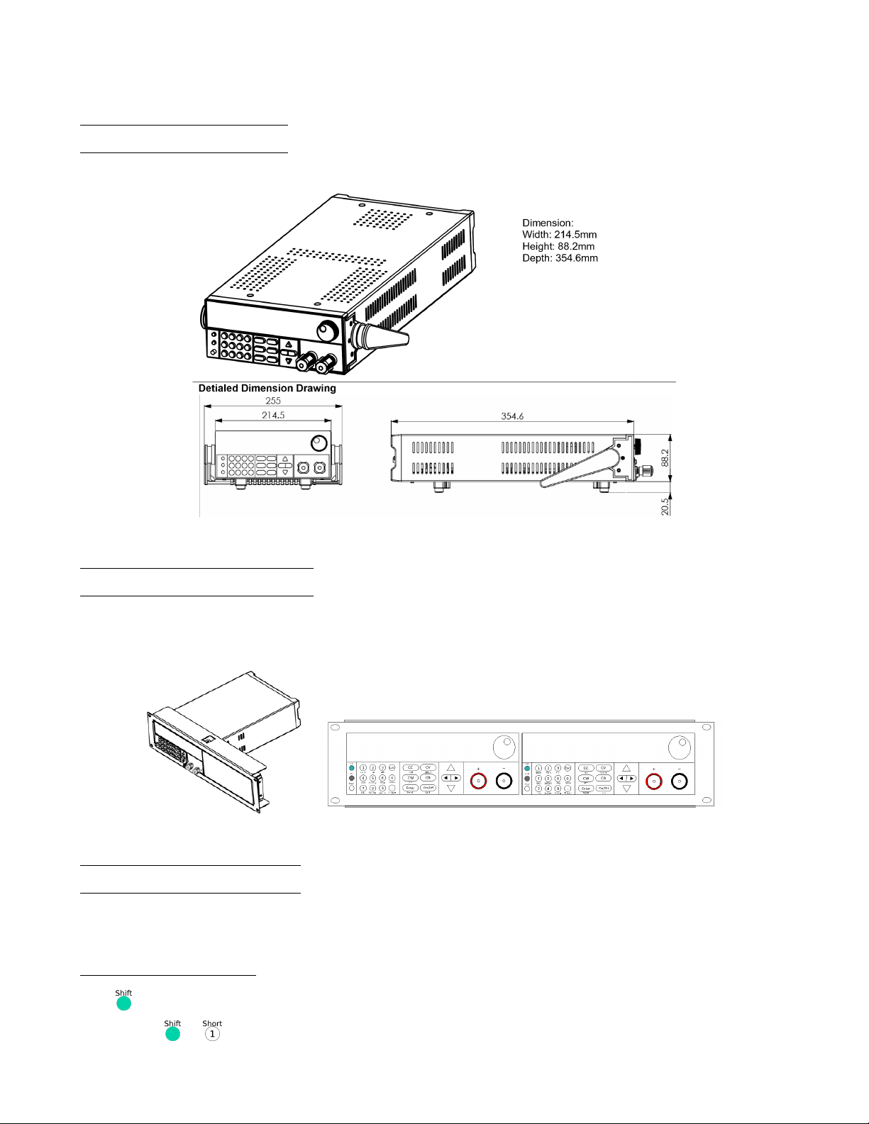
1.3 Product Dimensions
All models are designed to t in a standard 19-inch rackmount. The dimensions are shown in Figure 1.1.
Figure 1.1 External Dimensions - Half-rack models
1.4 Rackmount Installation
The instrument can be installed in a standard 19 inch rack. For half-rack models, the optional rackmount kit IT-E151 is
required. Figure 1.2 shows one of the half-rack sized units using the IT-E151 rackmount kit. This rackmount kit also
accomodates up to two half-rack models installed side by side.
Figure 1.2 Half-Rack sized Unit
1.5 Front Panel Overview
See Figure 1.3.
1.5.1 Combination Keys
Press button rst and then other keys to activate the more advanced functions.
+ Turn short circuit on or off.
6
Page 7
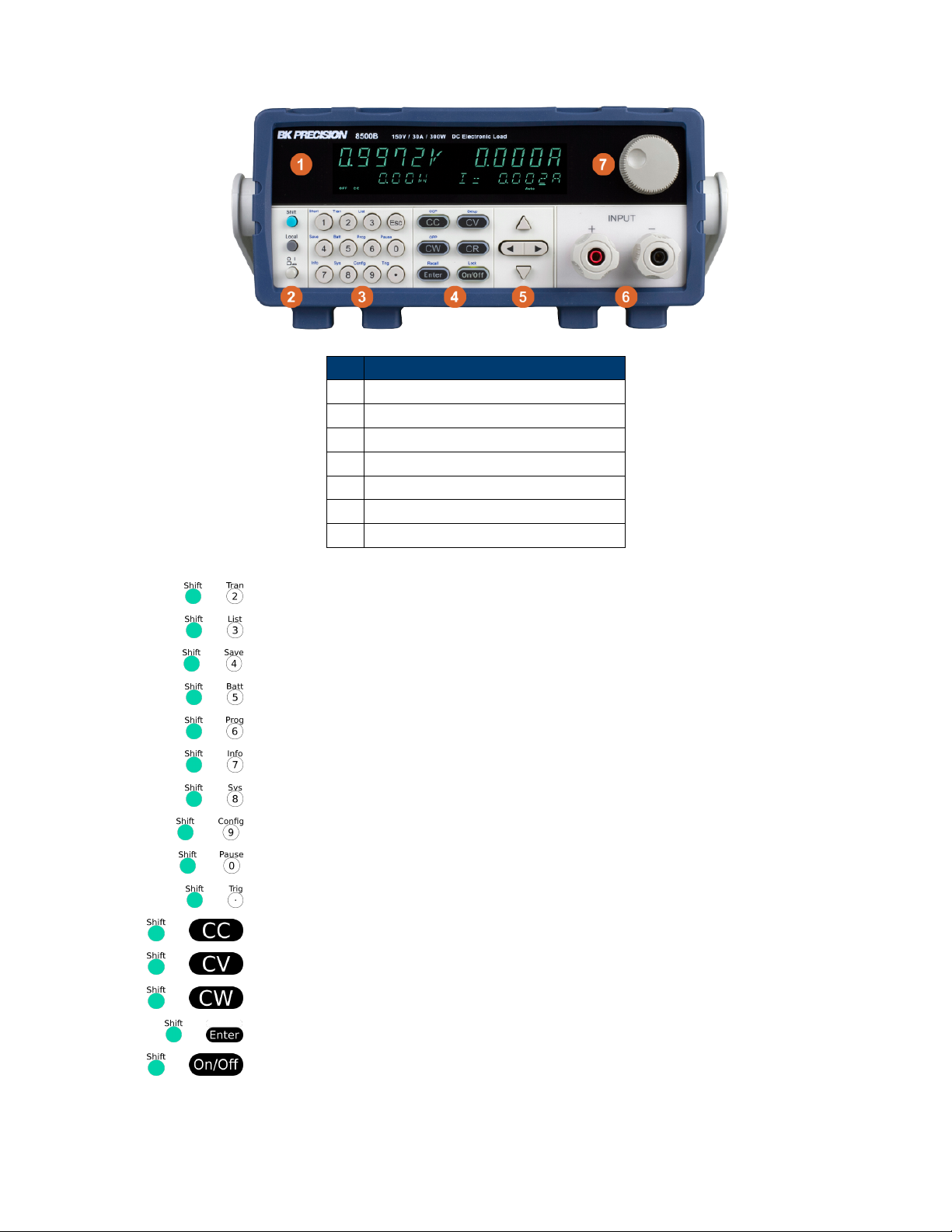
Item Description
1 VFD Display
2 Power Switch and Function Keys
3 Numeric Input and Advanced Functions
4 Mode keys and Input Control
5 Navigation Keys
6 Input Terminals
7 Rotary Input Knob
Figure 1.3 Front Panel
+ Start or stop transient condition.
+ Set LIST operation parameters.
+ Store the DC Load state in non-volatile memory.
+ Turn on or off battery testing function.
+ Enter auto test function.
+ Display product’s Model/SN/Version.
+ System menu setting
+ Congure menu setting
+ Press this button if you need a pause when runing an auto test le.
+ Cause an immediate trigger.
+ Enter OCP test function.
+ Set detailed parameters in CC/CV/CW/CRmode.
+ Enter OPP test function.
+ Recall the DC Load state from non-volatile memory.
+ Key lock function
7
Page 8
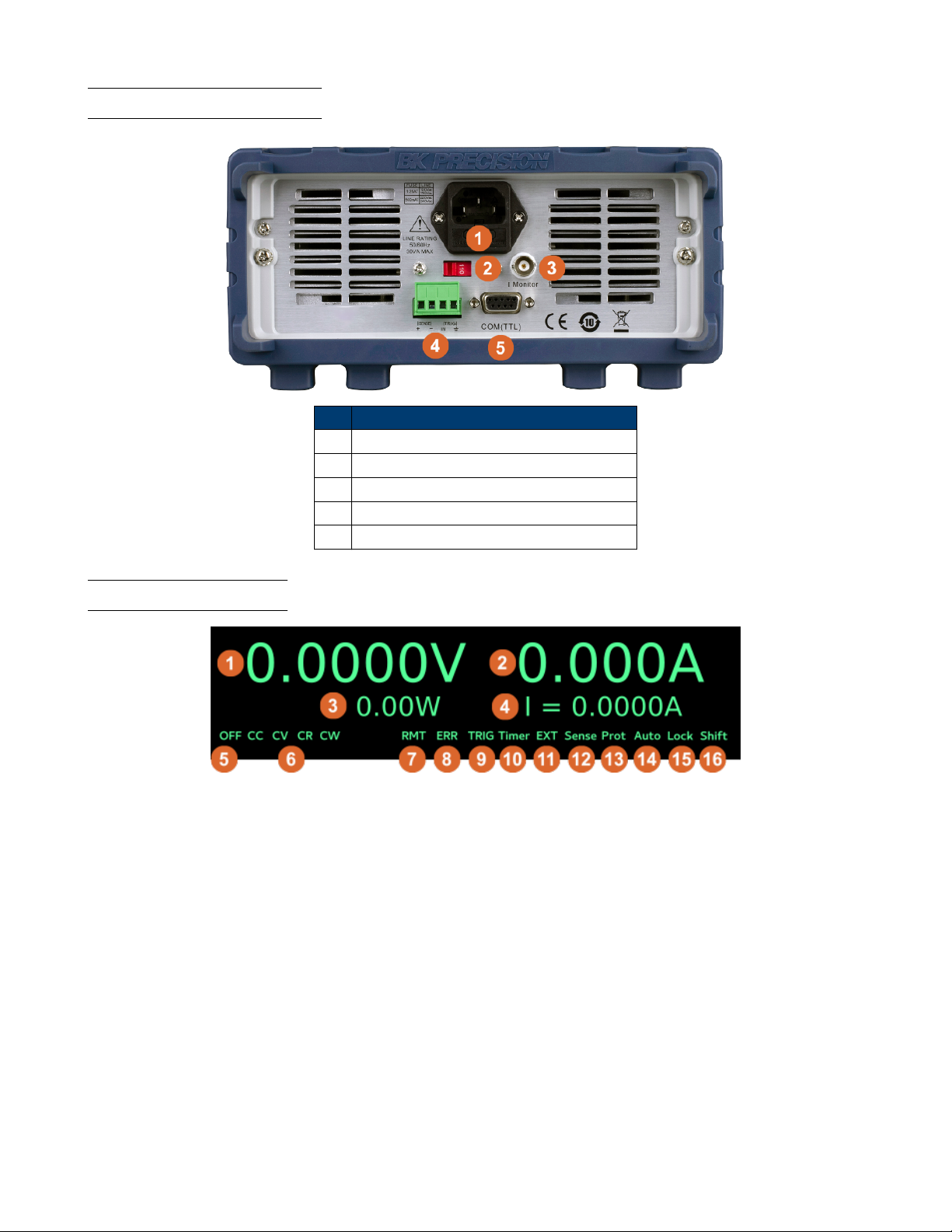
1.6 Rear Panel Overview
Item Description
1 Power Input and Fuse Holder
2 AC Voltage Switch
3 Current Monitor Output
4 Remote Sense and Trigger Input
5 TTL (5V) Communication DE-9 Connector
1.7 Display Overview
8
Page 9

Item Description
1 Measured Voltage
2 Measured Current
3 Measured Power
4 Set Value
5 Input Off indicator, lit when input is off
6 Operation mode indicators (CC, CV, CW, CR)
12 Remote control active indicator
13 Error indicator
14 Waiting for Trigger indicator
15 Timer indicator
16 External indicator
16 Remote Sense active indicator
17 Protection event indicator
18 Auto range
19 Key Lock indicator
20 Shift indicator
9
Page 10
Getting Started
Before connecting and powering up the instrument, please review and go through the instructions in this chapter.
2.1 Input Power
The load has a selectable AC input that accepts line voltage input within:
Voltage Frequency
115 V (+/-10%) or 230 V (+/- 10%) 47 Hz – 63 Hz
Table 2.1 Input Power Requirements
Use the line voltage selector switch in the back to switch between 110 V and 220 V operation.
Disconnect all cables including the power cord from the instrument when changing the instrument’s line
voltage. After changing the line voltage setting, ensure the instrument has fuses of the proper ratings and types for
the selected line voltage before applying line power.
2.2 Fuse Requirements
An AC input fuse is necessary when powering the instrument. Below is a table of the fuse required for all models operating
with either 110 VAC or 220 VAC input. See Table ??. The fuses are 5mm x 20mm High Energy Slow Blow type
(ceramic casing with sand ll).
Model Fuse Specication (110 VAC) Fuse Specication (220 VAC)
8542B 1.25 A, 250 V 500 mA, 250 V
8500B 1.25 A, 250 V 500 mA, 250 V
8502B 1.25 A, 250 V 500 mA, 250 V
8510B 3.15 A, 250 V 1.6 A, 250 V
Table 2.2 Fuse Ratings
2.2.1 Fuse Replacement
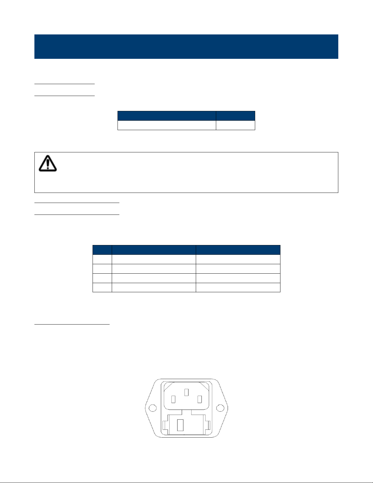
Follow the steps below to replace to check the fuse:
1. Locate the fuse box next to the AC input connector in the rear panel, see Figure 2.1.
2. With a small at blade screwdriver, insert into the fuse box slit to pull and slide out the fuse box as indicated below.
3. Check and replace fuse (if necessary) for the desired line voltage operation.
Figure 2.1 Fuse Holder
10
Page 11
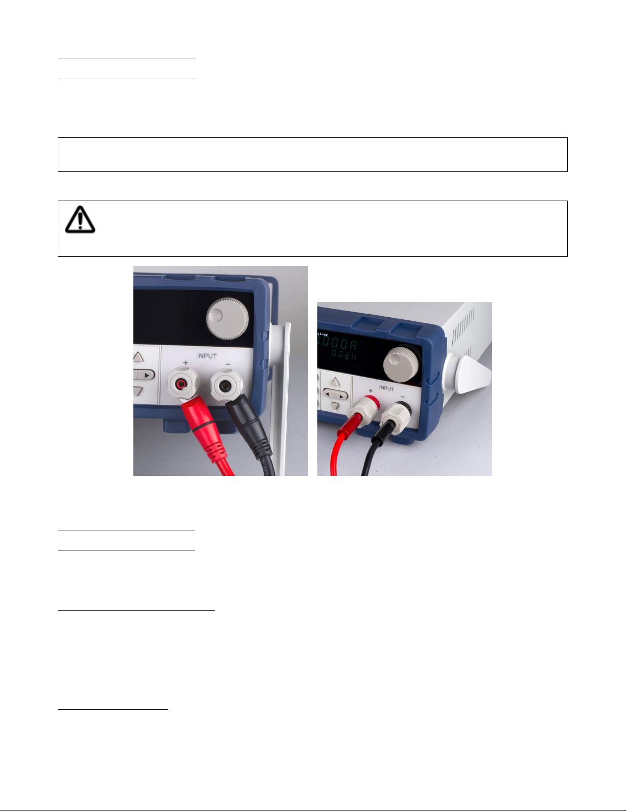
2.3 Input Connections
The main DC input terminal is a screw type binding post terminal located in the front panel, holes are included for
inserting wires, and the binding post also includes “banana jack” connections. Each connection allows for different
current levels. The “banana” input is capable of up to 10 A of current. Any more current is not recommended and could
lead to excessive connector heating, melting and worse.
Note: The screws on the terminals can be completely removed to allow for ring type adapters. The screw posts are
7mm in diameter.
Due to the high current rating of the DC load, proper wire sizes are necessary for safe connectivity and to prevent wires
from overheating.
Before connecting wires to the input terminals, turn OFF the load to avoid damage to the instrument and
the device under test (DUT).
High Current Connection Low (<10 A) Current Connection
Figure 2.2 Input Connections
2.4 Preliminary Check
Complete the steps in this section to verify that the load is ready for use.
2.4.1 Verify AC Input Voltage
Verify and check to make sure proper AC voltages are available to power the instrument. The AC voltage range must
meet the acceptable specication as explained in Section ??.
Connect AC power cord to the AC receptacle in the rear panel and press the power switch to the ON position to turn
ON the instrument. It will run through a self test procedure with the screen shown below:
2.4.2 Self-test Errors
Connect AC power cord to the AC receptacle in the rear panel and press the power switch to the ON position to turn
ON the instrument. Various elements of the system are checked during the power-on self test routine. If any occur, they
11
Page 12
are reported during the power-up procedure. See Section 11 for troubleshooting and error information details. During
self-test, the display displays “System Init”, and dots are displayed showing the test progress level.
2.4.3 Input Check
Follow the steps below to check that the load is operating correctly, and that the load elements (power transistors) are
not damaged. A DC power supply rated for at least 5V and 1 A is required for this check.
1. Connect the input terminal to a DC power supply and congure the supply to output 5 V and current limit to 1 A.
2. Power on the load. The display will show the “OFF” annunciator above the voltage display.
3. Turn on the DC power supply’s output. Observe the load’s measured voltage display, it should read approximately 5
V.
4. Press the “CC” button to enable the constant current load mode.
5. Use the keypad to enter 0.5 A. Press the Enter key to set the value.
6. The display should show CC = 0.500A on the bottom right.
7. Press “On/Off” to enable the load. The “On/Off” button should light up, and the “Off” indicator on screen should
disappear. The measured current should now display a value close to 0.5 A.
8. This setup veries that the load is drawing power correctly from the power supply.
If the load does not show 5 V, or shows signicant current draw from the connected power supply, the load may be
damaged and need service. If when the supply is connected, showing 5 V on the load’s display, and no current is drawn,
the load may be damaged and need service.
Note: If the load is not drawing power from the DC power supply, check all load protection limits and settings within
the menu to verify that the load is congured to allow drawing power at 5V, 0.500 A. Also, verify that the CC mode
parameters are setup to operate within the congured valid ranges by pressing +
If after checking all of the above, and verifying the power supply used for testing is not at fault, contact B&K for further
assistance.
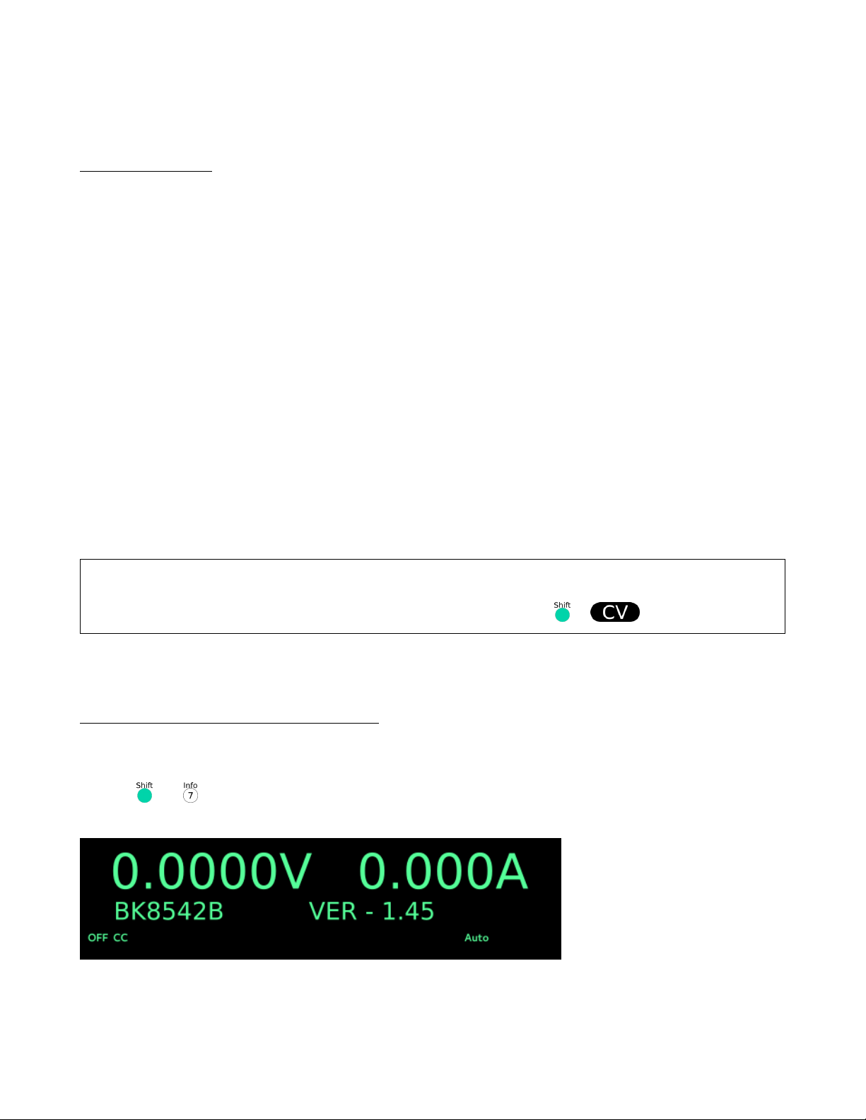
2.4.4 Check Model and Firmware Version
The model and rmware version can be veried by using the *IDN? query remote command. It can also be found from
the front panel:
1. Press and
2. The display will show the following:
3. This shows the model to be a BK8542B with Firmware: 1.45
4. Press (esc) to return to the normal display.
12
Page 13

Front Panel Operation
The electronic load provides the following modes:
• Constant current (CC) operation mode
• Constant voltage (CV) operation mode
• Constant resistance (CR) operation mode
• Constant power (CW) operation mode
3.1 Local Mode/Remote Mode
The 8500B series can either be operated locally or remotely. When in “Remote” mode, the RMT indicator will be lit.
When in this mode, the front panel of the load is disabled and all commands are issued via the serial interface. In order
to exit “Remote” mode and work in “Local” mode, press the “Local” button. This is the small grey button on the left
hand side of the numeric keypad.
3.2 Constant Current (CC) Mode
In this mode, the load will draw the specied current as long as the source is capable of delivering it. The load uses
transistors in parallel to implement the load circuit, and as such there are some limits. For example, the load has a nite
minimum resistance determined by the RdsOn of the transistors. Next, given the resistance limits, there is a limit to the
amount of current that may be drawn for a given voltage. The datasheet shows curves for this limit in the section called
“Low Voltage Operation”. Please refer to the datasheet for details for each model.
3.2.1 Congure CC Parameters
There are several parameters that should be setup prior to operating in CC mode. First, enable the “CC” mode of
operation by pressing the CC mode key. Next, enter the setup menu by pressing “Shift” and then the “CV” key. Above
the “CV” key, “Setup” is written. The following are the available menu items, scroll through them with the up/down
arrow keys or by entering a value and pressing enter.
Range This denes the maximum allowed current set value. Use this limit to protect against acciden-
tally entering excessive current values either from the keypad or dial.
High This is the voltage high limit for the automatic test mode, it does not apply otherwise. During
automatic test mode, the device under test (DUT) must be operating below the congured value
for the test to PASS upon completion. If the DUT operates above the congured value, the test
will FAIL upon completion.
Low This parameter refers to the voltage low limit for the automatic test mode. During automatic
test mode, the DUT must be operating above the congured value for the test to PASS upon
completion. If the DUT operates below the congured value, the test will FAIL upon completion.
Rise Up/ Fall Down These parameters dene the current slew rate of the load as it changes to a new programmed
value. The programmed slew rate takes effect immediately when set, so if the transient or triggered modes are active, it will apply immediately.
13
Page 14

3.3 Slew Rate Measurement and Actual Transition time
Current slew rate is dened as the change in current over time. A programmable slew rate allows a controlled transition
from one load setting to another. The actual transition time is dened as the time for the input to change from 10% to
90%, or 90% to 10% of the programmed current values. The graph below illustrates slew rate measurements.
Between the 10% and 90% region, the slew rate can be measured by observing the steepest slope portion. In case of very
large load changes, e.g. from no load to full load, the actual transition time will be larger than the expected (measured)
time. For this reason, the rmware allows the user to program slew rate values outside of the specied slew rate ranges.
The minimum transition time for all programmable slew rates is also limited in cases where the transition from one setting
to another is very small, due to bandwidth limitations of the load.
3.4 Constant Voltage (CV) Mode
In this mode, the electronic load will attempt to sink enough current to control the source voltage to the programmed
value.
3.4.1 Congure CV Parameters
There are several parameters that should be set up prior to operating in CV mode. Press so that it lights up, then press
) and to access Setup for CV mode. The setup menu will be shown:
Range This value will also act as a limit to how much voltage the load can be congured.
High This is the current upper limit for the automatic test mode. The system must be operating be-
low the congured value for the test to PASS upon completion. If the DUT operates above this
value, the test will FAIL.
Low This is the current lower limit for the automatic test mode. The system must be operating be-
low the congured value for the test to PASS upon completion. If the DUT operates below this
value, the test will FAIL.
3.5 Constant Power (CW) Mode
In this mode, the electronic load will consume a constant power. When input voltage increases, the input current will
decrease, while power (P = V*I) will remain the same. This is a sampled system, so the performance is not as fast as in
CC and CV modes.
3.5.1 Congure CW Parameters
There are several parameters that should be set up prior to operating in CW mode. Press
so that it lights up, then press )and to access “Setup” for CW mode. The setup menu will be shown:
The setup parameters are: Range, High (Voltage limit), and Low (Voltage limit). Use the
) keys to select each parameter, and use the numeric keypad to change the value. Press to conrm the change.
Range This value will also act as a limit the allowed power setting value.
High This parameter sets the upper voltage limit for the automatic test mode. If the voltage exceeds
this upper limit during the test, the test will fail.
High This parameter sets the lower voltage limit for the automatic test mode. If the voltage exceeds
this lower limit during the test, the test will fail.
14
Page 15

3.6 Constant Resistance (CR) Mode
In this mode, the electronic load approximates a resistor. The current draw is varied by the load according to the input
voltage. The performance of this mode is not as fast as in CC or CV mode. This is because it is a sampled system and
response to changing input takes a nite amount of time.
3.6.1 Congure CR Parameters
There are several parameters that should be set up prior to operating in CR mode. Press
so that it lights up, then press )and to access Setup for CR mode. The setup menu will be shown:
The setup parameters are: Range, High (Voltage limit), and Low (Voltage limit). Use the (arrow keys) key to select each
parameter, and use the numeric keypad to change the value. Press (enter) to conrm the change.
Range This value will also act as a limit the allowed resistance setting value.
High This parameter sets the upper voltage limit for the automatic test mode. If the voltage exceeds
this upper limit during the test, the test will fail.
High This parameter sets the lower voltage limit for the automatic test mode. If the voltage exceeds
this lower limit during the test, the test will fail.
15
Page 16

Front Panel Operation
The electronic load provides the following modes:
• Constant current (CC) operation mode
• Constant voltage (CV) operation mode
• Constant resistance (CR) operation mode
• Constant power (CW) operation mode
4.1 Local Mode/Remote Mode
The 8500B series can either be operated locally or remotely. When in “Remote” mode, the RMT indicator will be lit.
When in this mode, the front panel of the load is disabled and all commands are issued via the serial interface. In order
to exit “Remote” mode and work in “Local” mode, press the “Local” button. This is the small grey button on the left
hand side of the numeric keypad.
4.2 Constant Current (CC) Mode
In this mode, the load will draw the specied current as long as the source is capable of delivering it. The load uses
transistors in parallel to implement the load circuit, and as such there are some limits. For example, the load has a nite
minimum resistance determined by the RdsOn of the transistors. Next, given the resistance limits, there is a limit to the
amount of current that may be drawn for a given voltage. The datasheet shows curves for this limit in the section called
“Low Voltage Operation”. Please refer to the datasheet for details for each model.
4.2.1 Congure CC Parameters
There are several parameters that should be setup prior to operating in CC mode. First, enable the “CC” mode of
operation by pressing the CC mode key. Next, enter the setup menu by pressing “Shift” and then the “CV” key. Above
the “CV” key, “Setup” is written. The following are the available menu items, scroll through them with the up/down
arrow keys or by entering a value and pressing enter.
Range This denes the maximum allowed current set value. Use this limit to protect against acciden-
tally entering excessive current values either from the keypad or dial.
High This is the voltage high limit for the automatic test mode, it does not apply otherwise. During
automatic test mode, the device under test (DUT) must be operating below the congured value
for the test to PASS upon completion. If the DUT operates above the congured value, the test
will FAIL upon completion.
Low This parameter refers to the voltage low limit for the automatic test mode. During automatic
test mode, the DUT must be operating above the congured value for the test to PASS upon
completion. If the DUT operates below the congured value, the test will FAIL upon completion.
Rise Up/ Fall Down These parameters dene the current slew rate of the load as it changes to a new programmed
value. The programmed slew rate takes effect immediately when set, so if the transient or triggered modes are active, it will apply immediately.
16
Page 17

4.3 Slew Rate Measurement and Actual Transition time
Current slew rate is dened as the change in current over time. A programmable slew rate allows a controlled transition
from one load setting to another. The actual transition time is dened as the time for the input to change from 10% to
90%, or 90% to 10% of the programmed current values. The graph below illustrates slew rate measurements.
Between the 10% and 90% region, the slew rate can be measured by observing the steepest slope portion. In case of very
large load changes, e.g. from no load to full load, the actual transition time will be larger than the expected (measured)
time. For this reason, the rmware allows the user to program slew rate values outside of the specied slew rate ranges.
The minimum transition time for all programmable slew rates is also limited in cases where the transition from one setting
to another is very small, due to bandwidth limitations of the load.
4.4 Constant Voltage (CV) Mode
In this mode, the electronic load will attempt to sink enough current to control the source voltage to the programmed
value.
4.4.1 Congure CV Parameters
There are several parameters that should be set up prior to operating in CV mode. Press so that it lights up, then press
) and to access Setup for CV mode. The setup menu will be shown:
Range This value will also act as a limit to how much voltage the load can be congured.
High This is the current upper limit for the automatic test mode. The system must be operating be-
low the congured value for the test to PASS upon completion. If the DUT operates above this
value, the test will FAIL.
Low This is the current lower limit for the automatic test mode. The system must be operating be-
low the congured value for the test to PASS upon completion. If the DUT operates below this
value, the test will FAIL.
4.5 Constant Power (CW) Mode
In this mode, the electronic load will consume a constant power. When input voltage increases, the input current will
decrease, while power (P = V*I) will remain the same. This is a sampled system, so the performance is not as fast as in
CC and CV modes.
4.5.1 Congure CW Parameters
There are several parameters that should be set up prior to operating in CW mode. Press
so that it lights up, then press )and to access “Setup” for CW mode. The setup menu will be shown:
The setup parameters are: Range, High (Voltage limit), and Low (Voltage limit). Use the
) keys to select each parameter, and use the numeric keypad to change the value. Press to conrm the change.
Range This value will also act as a limit the allowed power setting value.
High This parameter sets the upper voltage limit for the automatic test mode. If the voltage exceeds
this upper limit during the test, the test will fail.
High This parameter sets the lower voltage limit for the automatic test mode. If the voltage exceeds
this lower limit during the test, the test will fail.
17
Page 18

4.6 Constant Resistance (CR) Mode
In this mode, the electronic load approximates a resistor. The current draw is varied by the load according to the input
voltage. The performance of this mode is not as fast as in CC or CV mode. This is because it is a sampled system and
response to changing input takes a nite amount of time.
4.6.1 Congure CR Parameters
There are several parameters that should be set up prior to operating in CR mode. Press
so that it lights up, then press )and to access Setup for CR mode. The setup menu will be shown:
The setup parameters are: Range, High (Voltage limit), and Low (Voltage limit). Use the (arrow keys) key to select each
parameter, and use the numeric keypad to change the value. Press (enter) to conrm the change.
Range This value will also act as a limit the allowed resistance setting value.
High This parameter sets the upper voltage limit for the automatic test mode. If the voltage exceeds
this upper limit during the test, the test will fail.
High This parameter sets the lower voltage limit for the automatic test mode. If the voltage exceeds
this lower limit during the test, the test will fail.
4.7 CR-LED Test Function
The Constant Resistance LED mode roughly simulates a diode characteristic. There are 2 main parameters that are set
to accomplish this, the overall resistance and diode threshold voltage (Vd). At input voltages above the threshold (Vd),
the resistance of the load decreases. For example, set the Vd to 1.6 V, R to 0.1 and connect a current limited power
supply. Set the power supply voltage limit to 5 V, and the current limit to 300 mA. When the input is enabled, the
voltage at the input will be approximately 1.6 V, and the current will be 300 mA. This is equivalent to a resistance of 16
Ohms, much larger than the set value of 0.1 Ohms. See Table 4.1.
Like in CR mode, a resistance value is also set. This value sets the slope of the diode characteristic. A 3 V VD, 0.1
Ohms, and 1.38 A results in 3𝑉 + 0.1Ω ∗ 1.38𝐴 = 3.18𝑉.
Voltage Current Equivalent Load Resistance
1.00 0 innite
1.58 15mA 105 Ohms
1.62 0.215 A 7.5 Ohms
1.63 0.3 5.4 Ohms
1.69 1 A (limit changed) 1.7 Ohms
Table 4.1 CR Mode example
4.7.1 Setup
Enable CR-LED mode via + . Use the arrow keys to move the ashing value “ON”. Press to conrm
and move on. The next screen shows the VD value. Enter the desired threshold voltage and press . CR LED mode
is now setup.
Note: As in CR mode, the control system speed can make loading switching power supplies problematic.
18
Page 19

Rear Panel Functions
Item Description
1 Power Input
2 Fuse Holder
3 AC Input Voltage Selection
4 Current Monitor Output
5 Remote Sense/Trigger Input
6 Remote Interface
Figure 5.1 Rear Panel
5.1 Remote Sensing
Remote sensing is used to counteract the effect of lead resistance. For example, if you connect a power supply to the DC
Load, the voltage at the power supply’s terminals will not be the same as the voltage at the DC Load’s terminals if there
is a current owing because of the nite resistance from the wires. Using remote sensing, you can sense the voltage at
the power supply’s terminals, effectively removing the effect of the voltage drop in the connection wire.
Connect the “+” and “-” terminals at the rear of the unit to the power source.
Note:To reduce interference, twist the sense lines together and run together with the wires connecting the load to
the source.
Note:When using remote sensing, the power displayed by the instrument includes both the power dissipated inside
the instrument and the power dissipated in the leads from the power supply to the DC Load’s input terminals.
1. Press + to enter the conguration menu.
2. Use the arrow keys to navigate to the “SENSE” menu item. Press to enter the menu.
3. Use the arrow keys to select the desired value “ON, or OFF” and press to conrm the setting.
4. When active, the “Sense” indicator will show on the display.
5.2 External Triggering
An external trigger is a TTL low signal applied to the Trigger connection on the back panel. This TTL signal must last
for more than 5 ms. A trigger applied to this input can be used to change settings (voltage, current ,resistance), toggle
between settings in transient-toggle mode, or generate a pulse in pulse mode.
1. Press + .
2. Use the arrow keys or the knob to navigate to the “TRIGGER” menu item.
3. Select “EXTERNAL” and press to conrm the setting.
19
Page 20

5.3 Current Monitoring (I Monitor)
The current monitor output, the bnc connector, outputs a scaled voltage relative to the current owing. The relationship
is 𝑉
𝑜𝑢𝑡
= 10𝑉 ∗
monitor output will be 10𝑉 ∗
𝑐𝑢𝑟𝑟
. For example, the 8542B maximum current is 30 A. When a current of 1 A is owing, the current
𝑚𝑎𝑥
1
= 333𝑚𝑉.
30
Note: The output accuracy is approximate. Verify the scaling relationship for each unit.
20
Page 21

Advanced Functions
In addition to the 4 general modes of operation, there are a number of other more application specic functions. These
functions enable more advanced testing.
6.1 Short Operation
The electronic load can simulate a short circuit at its input. During front panel operation, press + to switch the
short on/off state. Short operation will not affect the present setting. When turning off the short state, the load returns
to the original set state. The actual value of the electronic load in short operation depends on the mode and range that
is active when the short is turned on. In CC or CR mode, the maximum short current is typically 110% of the current
range. In CV mode, short means setting the load’s constant voltage to be 0 V. In short operation mode, you can measure
the maximum short current (Amax) or DC current (ADC) of the power source to be measured. You can set this function
via the Conguration menu.
6.2 Short-circuit Analog Function
Short circuit simulation and short circuit current measurement:you may press [ Shift ] + [ 1 ] botton to emulate a short
state.It can be used to check whether the tested instrument’s short protection is avaiable.
In short mode,the DC load will draw maximum current from the DC supply in any of the four operation modes(CC,CV,CW
or CR).In CC,CV,or CR mode,you may press [ Shift ] + [ 1 ] to stop short.The DC load will return to its previous
operation.However,in CW mode,the short current will continue to be drawn.To stop the short,you must press the [On/Off]
key after you press [ Shift ] + [ 1 ]. When emulating a Short in CC, CW or CR mode, the maximum allowable short
current is equal to the 110% of current range. Under CV mode, short circuit current is equivalent to that constant
voltage value of load is 0 V.
6.3 Transient Operation
Transient mode periodically switches between two load levels. There are three different transient modes:
Continuous Generates a respective pulse stream that toggles between two load levels.
Pulse Generates a load change that returns to its original state after some time period.
Toggle Generates a repetitive pulse stream that toggles between two load levels. It is similar to contin-
uous mode except that the transient points are controlled by explicit triggers instead of an internal transient generator.
Depending on the selected Trigger Source from within the “SYSTEM” menu, the operation may start immediately.
To run the transient operation, rst press to enable the input. Then, send a trigger to start the operation. If Trigger
Source is set to “Manual”, press and then (or press ) to send a trigger. Refer to “Congure Trigger Source” in section
“SYSTEM Menu” to congure the Trigger Source.
Note: The number next to “TRAN” on display will count each transition. It can only count up to 65535 transitions,
after which it will reset to 0 and start over.
To disable transient operation, rst press to disable the input. Then, press and (or press ). Select “Off” and press to
conrm.
21
Page 22

1. First, select the load’s mode of operation, which will determine which type of transient operation will be congured.
Press or to select between CC, CV, CW, or CR mode. Verify the selection by the backlight behind its corresponding
button, which will be lit when selected.
2. Enable transient mode from the “Tran” menu. This is accessed via “ + ”.
3. Select the transient mode “Continuous”, “Pulse”, or “Toggle”. Press .
6.3.1 CC Mode
In Constant Current mode, the congurable parameters are the following:
Mode Continuous, pulse, or toggle
Up The rising edge current slew rate in A/us.
Down The falling edge slew rate in A/us.
Level A, Level B The 2 current levels applied.
In Continuous mode, the following are also set:
Freq The transient cycle frequency.
Duty The duty cycle or percentage of time the load will be at either level (A/B). The percentage de-
nes the ratio of the B level to the cycle. So for 75% and 1 Hz, the B level will be on for 750
ms and the A level 250 ms.
In Pulse Mode, the following is also set:
Width The transient frequency
6.3.2 CV, CW, and CR modes
In Constant Voltage, Power and Resistance modes, the congurable parameters are the following:
Mode Continuous, pulse, or toggle
Level A, Level B The 2 levels.
In Continuous mode, the following are also set:
Freq The transient cycle frequency.
Duty The duty cycle or percentage of time the load will be at either level (A/B). The percentage de-
nes the ratio of the B level to the cycle. So for 75% and 1 Hz, the B level will be on for 750
ms and the A level 250 ms.
In Pulse Mode, the following is also set:
Width The transient frequency
6.4 LIST Operation
List mode allows you to generate a complex current sequence. Moreover, the mode change can be synchronized with an
internal or external signal to accomplish dynamic and precise test. A list le includes following parameters: le name,
step count (range 2-84), step width (0.00005 s - 3600 s), step value and slope. The list le is saved in memory for later
recall. There is storage for up to 7 list programs. In list mode, the load starts the list following a trigger signal. The list
will continue run to completion or until another trigger signal is received.
22
Page 23

Figure 6.1 List Mode Current Waveform
6.4.1 Congure List
Lists are run exclusively from internal memory only. As in other menus, an active eld is denoted by an underline cursor
or ashing. To enter a list into memory, complete the following:
1. Press + .
2. Set the rst eld in the menu to “OFF”. If the eld is set to “ON”, press to change the value to “OFF”.
3. Move the selected eld via the buttons to the “EDIT” (shown as EDI) eld and press to start editing a
List. If nothing happens, ensure the rst eld is set to “OFF”.
4. Set the current range.
5. Set the number of steps in the list. This is a value between 2 and 84.
6. Set the rst step’s current, slew rate, and step time.
7. The next step in the list will prompt automatically. Enter the values for each step in the same way.
8. When each step is entered, the system prompts for the number of times to run the sequence. A 1 in this eld means
the sequence will run only once.
9. Enter the list le location to store the newly created list.
The list is now saved and may be recalled.
6.4.2 Run List
1. Select the list to run:
1. From the “List” menu, select “CALL” and press .
The load prompts for the list to recall (1 through 7).
2. Enter the list number and press to recall it.
2. Enable List mode by selecting the “Off” menu item and press .
The “OFF” changes to “ON” and the “Trig” indicator lights.
23
Page 24

3. Use the button to go back to the normal display. The load is now ready and waiting for a trigger.
4. Press to enable the input, and send a trigger to start the list program.
If Trigger Source is set to Manual, press + to send a trigger. See Section ?? for details about triggers.
Note: The number next to LIST on the display shows the current running step number. When the list ends, it will
change back to “0”.
Note: At the end of a list operation, the load’s input remains on the settings of the last step value.
6.4.3 Disable List Mode
1. Disable the input via the or remote command.
2. Press +
3. Select the “ON” item and press to change the value to conrm. The “Trig” indicator will disappear.
6.5 Battery Test Function
The 8500B series products include battery test capabilities. This function provides a constant current load. The test
records the time, and charge consumed in Amp-hours. Three independent conditions are available to customize the test.
These are voltage, charge (Ah), and time.
Stop conditions are not optional. If one of the conditions is not required for a test, then the value should be set so
that it will not trigger. For example, if the capacity is unimportant to the test, set the value to maximum (999.999
Ah).
The run the battery test function a conguration is loaded into memory, the battery test mode is then enabled, and
nally the mode is started by a trigger signal.
6.5.1 Test Conguration
To congure a battery test, the “RUNMODE” must be set to “NORMAL”. See Section ?? for details.
1. Press +
2. The battery test parameters menu will open.
3. Set the parameters of the test:
Range The maximum current allowed. Set to a value equal to or higher than the desired discharge
current.
Current The discharge current for the test.
Stop Voltage The lower limit voltage for the battery.
Stop Cap (Capacity) The maximum capacity to discharge. For example, 50% discharge of a 10 Ah battery, this
would be 5 Ah.
24
Page 25

Stop Timer The maximum test time.
4. When the settings are entered, the last step is to set the memory location. Set the value (1 - 10) and press to
complete the conguration entry.
6.5.2 Enable Battery Test Mode
1. Press + to enter the system menu.
2. Use the keys to navigate to the ‘RUNMODE’ setting.
3. Press to enter the setting menu.
4. Use the to scroll through the different settings and select “BATTERY”.
5. After setting the mode, exit the menu using the .
Battery test mode is now enabled.
6.5.3 Recall Battery File
Press + to select program le, the panel displays “RECALL BATTERY 1”. Enter the le name (1-10) and
press button.
6.5.4 Start Battery Test
With the battery mode enabled, the load will work in a limited CC mode. If the battery test conditions are met, the input
may be enabled, and the battery mode test current will be drawn. If the limits are not met, the input will automatically
turn off.
To start a battery test, send a trigger to the load. In manual trigger mode, press the . The battery test will automatically
terminate when the stop conditions are met.
6.6 Program Mode
Test les are a generalization of lists. They generate a sequence of tests using different modes, mode parameters, and
durations. They are useful for executing a set of tests on a device, then displaying pass/fail results. Up to 10 groups of
test les can be dened. Each le contains 10 steps.
6.6.1 Example: Small AC/DC power supply test
Suppose we have a small AC to DC power supply (a “wall-wart”) and we want to set up an acceptance test for a number
of these devices.
1. Set the DC load to constant current mode to draw the rated current of 1.2A from the device. The output voltage of
the device at the rated current must be between 4.4V and 4.6V.
2. Set the DC load to constant voltage 3V. The output current of the device is between 2A and 3A.
3. When the device operates into a short, the supplied current must be larger than 3.0 A.
Steps Operation VFD Display
25
Page 26

1. Press + (Prog).
ACTIVE =0987654321
2. Press , and press enter to conrm.
ACTIVE =0987654YYY
3. Select the step that should pause during the test. When paused, press [downarrow] continue the test.
PAUSE=NNNNNNN32Y
4. Step 3 short circuit testing, press , and press to conrm.
SHORT =NNNNNNNY21
5. Set Ton for the rst step if you want to load on for 2S, press , and then press to conrm. T-on range 0-60S.
SEQ01 ON =2S
6. Set Toff for the rst step, if you want to load off 2S, press , and then press to conrm.
SEQ01 OFF =2S
7. Set testing delay time, 0-60S e.g. 1S, press [1].
SEQ01 P/F =1S
8. Set Ton for the second step, if you want to load 2S, press , then press Enter to conrm
SEQ02 ON =2S
9. Set Toff of the second step, if you need 2S, press , and then press to conrm.
SEQ02 OFF =2S
10. Set testing delay time of the second step, e.g. 1S, press
SEQ02 P/F =1S
11. Set Ton for the third step, if you want to load on 3S, press , then press to conrm
SEQ03 ON =3S
12. Set Toff of the third step, if you need 2S, press , then press to conrm.
SEQ03 OFF =2S
13. Set testing delay time of the third step, e.g. 2S, press .
SEQ03 P/F =2S
14. set start voltage. Please refer to “function of auto start voltage”.
AUTO START=0.000V
15. Set stop condition
STOP COMP FAILURE
Function of Auto Start Voltage:
1. Auto start=0V.
Auto test le start to run when receive a trigger signal by pressing +
2. Auto start is not equal to 0V (Take 2V as an example)
In this conditionuser only need to connect the charger to input termianls of E-load. The unit can auto start to run
test le when detect a rising edge from 0-2V. Auto start voltage is not suggested to be a big value.2V is suitable.
name:
or providing a external trigger signal.
images/trigButton
file:
images/trigButton
state:
unknown
26
Page 27
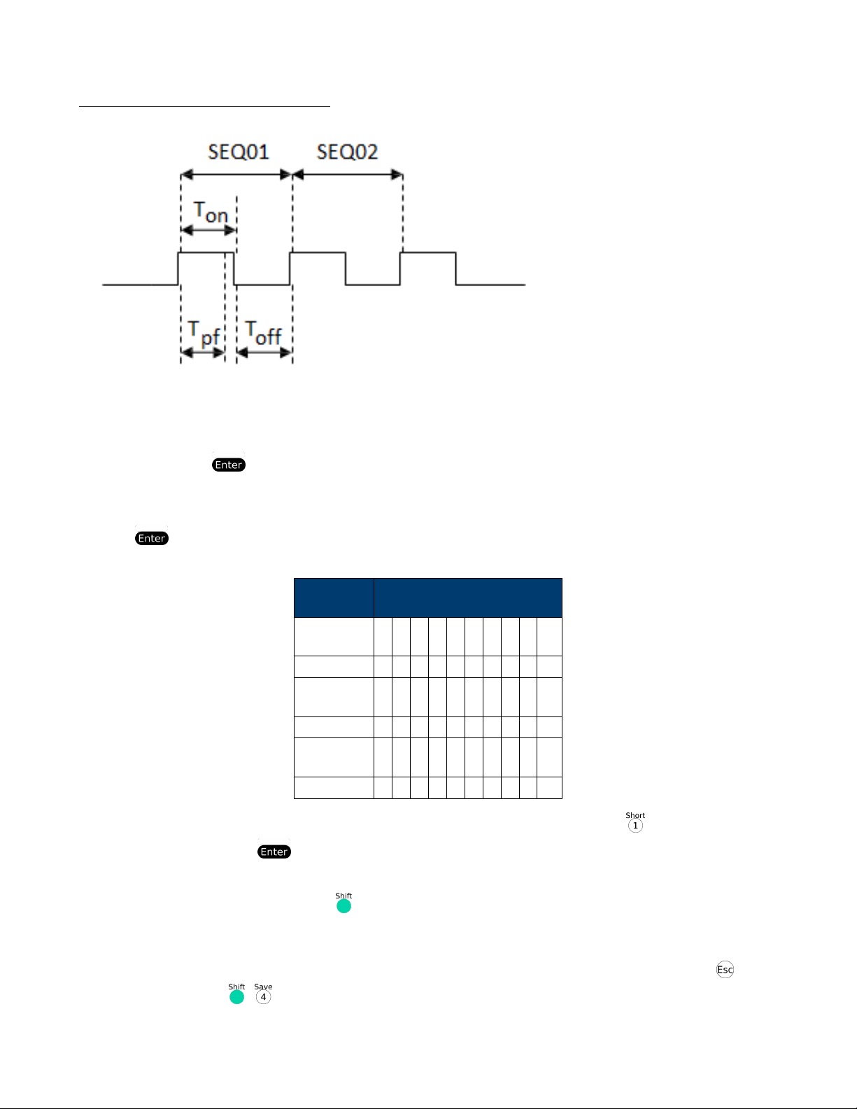
Ton, Toff and Tpf (P/F) Relation:
Tpf the delay time for a step
15. Set stop conditions: COMP means stop test when all the steps are completed, FAILURE means stop test when the
testing fails. Press to conrm.
STOP COMP FAILURE
16. Select the test le to link if you’d like to. The linked le must be saved before. 0 stands for not linking to other les.
Press key to conrm.
CHAIN PROGRAM =0(0-10)
Program/Save
PROGRAM
Sequence 1
Save Group 1 2 3 4 5 6 7 8 9 10
PROGRAM
Sequence 2
Save Group 11 12 13 14 15 16 17 18 19 20
PROGRAM
Sequence 10
Save Group 91 92 93 94 95 96 97 98 99 100
17. Save the edited les in EEPROM, you can save up to 10 groups of les, e.g please press to save the edited le
in group 1, and then press to conrm.
SAVE PROGRAM =1(1-10)
18. Select a operation mode and then press +[CV] to set related parameters
10.0000V 0.0000A
0.00W CC=1.000A
Locations
1 2 3 4 5 6 7 8 9 10
1 2 3 4 5 6 7 8 9 10
1 2 3 4 5 6 7 8 9 10
19. Edit the three steps of the test le, details refer to below procedure. After all the steps are set , Press to exit
setup, and then press + to save.
You need to recall the test le before runing it
27
Page 28

Set the steps of a test le in the example
CC Mode, 1.2A, Voltage Range 4.4V-4.6V
1. Press [[Shift)+[CC] buttonand then [CV] (Setup) to enter the setting interface.
RANGE=30.000A
CC
2. Set the current rangepress to conrm.
RANGE =1.2A CC
3. set the upper limit of voltage, press to conrm.
HIGH=4.6V
CC
4. Set the lower limit of voltage, press to conrm.
LOW=4.4V
CC
5. Set the rise speed of current, press to conrm.
UP=1A/uS
CC
6. Set the fall speed of current, press to conrm.
DOWN=1A/uS
CC
7. Finish the setup
10.0000V 0.000A
0.00W CC=0.000A
CV Mode, 3V, Current Range 2A 3A
1. Press [CV] buttonpress to set related +[parameters]
RANGE=120.00V
2. Set the voltage rangepress to conrm.
RANGE=3.00V
3. set the upper limit of currentpress to conrm.
HIGH=3A
4. Set the lower limit of currentpress to conrm.
LOW=2A
5. Finish the setup
10.0000V 0.000A
0.00W CV=10V
The CW and CR is set as the same way:
CW Mode
Steps Operation VFD Display
28
Page 29

1. Press [CW] buttonpress to set related +[parameters]
RANGE=150.00W
CV
2. Set the power rangepress to conrm.
RANGE =1.00W
3. Set the upper limit of voltagepress to conrm.
HIGH=120.00V
4. Set the lower limit of voltagepress to conrm.
LOW=0.000V
5. Finish the setup
10.0000V 0.000A
0.00W CW=1.00W
CR Mode
1. Press [CR] button, press [ +[CV] (Setup) to set related paramters.
RANGE=7500.0Ω
2. Set the resistance rangepress to conrm.
RANGE=2Ω
3. set the upper limit of voltagepress to conrm.
HIGH=120.0V
4. Set the lower limit of voltagepress to conrm.
LOW=0.000V
5. Finish the setup.
10.0000V 0.000A
0.00W CR=2.000Ω
Go into Autotest Mode
Operation Display on Front Pannel
1. Press + (system) to enter the system menu.
0.0000V 0.000A
POWER-ON BUZZER
2. Press right key, select RUNMODE and conrm with button.
0.0000V 0.000A RUN <NORMAL>
3. Press direction key to select OCP_TESTPress Enter to conrm.
0.0000V 0.000A RUN <PROG_TEST>
4. Press [Esc] button to leave the menu.
0.0000V 0.000A
P01
29
Page 30

According to the following steps to escape OPP mode:
Press + (system)—“RUNMODE”— —-select “NORMAL” mode— .
6.6.2 Start Auto Test File
Press []
are reached.
name:
to provide a signal to start auto test le. The discharing process will be auto terminated when stop conditions
images/triggerButton
file:
images/triggerButton
6.6.3 Recall Test File
state:
unknown
Press + button to select programe le the panel displays “RECALL PROGRAM= 1” Enter the le name(1-
10)press button to conrm.
If you need a pause, press + (pause). Press can continue the test.
6.7 Measurement of Voltage Rise Time
The 8500B series electronic load is provided with special voltage rise/drop time measurement function. This function
gives a simple analog of voltage rise/drop speed of oscilloscope test power.
Operation methods:
1 Set initial Voltage and Final Voltage
1. Press + keys to enter conguration menu. Press Right key. Select “Measure” and press key.
2. Press to select “TimeV1”. Press key. Press numeric keys to set initial voltage value and press key.
3. Press to select “TimeV2”. Press key. Press numeric keys to set nal voltage value and press key.
4. Press to exit setting. Start timer function
5. Press + keys to enter system menu. Press Right key till “Displ” icks and press key.
6. Press key to select “On”. Start timer function and press key.
7. Press to exit setting.
8. VFD second line will display time 0.0000S between power value and set value.
OFF CC
v-0.0002a 0.0001V 0.0002A
0.00W 0.0000S CC=0.000A
Measurement of Rise Time
9. Connect DC power to be tested to the input terminal of the electronic load. The power is set with a value that is
higher than the set nal voltage value. Keep power output in OFF status.
10. Set a constant current value on the load and open the load input.
11. Open power output.
30
Page 31

12. The electronic load timer starts timing. After ending, time will keep stable, which is rise time of voltage.
13. Close the power output. The electronic load VFD will display voltage drop time.
6.8 Ripple Function
The 8500B series DC electronic loads have test ripple function. You can read ripple voltage and ripple current by sending
instructions. See the programming manual for more information.
31
Page 32

Conguration Functions
7.1 VON Function
The DC load can be set to only turn on if the voltage is above a set value (VON set) under congure menu by pressing
+ . There are two types of VON function: “Living” and “Latch”. The following will have detailed description for
the two types.
NOTE
VON set is used to ensure an electronic system under test will not have power applied unless the supply voltage is above
a certain value. If you have no such testing request, do not set this value arbitrarily. If your instrument can not work
normally, for example, set CC=1 A, after turn on the input while the current is still 0 A instead of setting value 1 A,
then you should check VON set rstly. If VON set is not 0 V, then please modify to 0 V.
VON LIVING MODE In Living mode, when power is applied to the DC load, the voltage must rise above VON set-
ting before the load draws current from the source. If the voltge below VON setting on the load’s
terminals, the load will turn off input.
VON LATCH MODE In Latch mode,as before,the load will turn on only when the voltage exceed VON setting,but once
on,it will now stay on,even if the voltage drops to zero.
7.2 Menu Operation
How to Navigate the Menu
Before using the instrument, it is important to be familiarized with its menu structure and learn how to view or change
settings and parameters. Follow the steps below to guide you in selecting menu options.
1. Follow the instructions above to access the System or Cong menu.
2. The selected item will be blinking. Use and ) keys to move through the menu selections.
3. When the desired menu section is blinking, press to access its menu settings.
4. Below is the display when SYSTEM is selected.
7.3 System Menu
Initialize Power-On:
1. The selected item will be blinking. Use ) keys to move through the menu items. When there is a on the right side of
the display, that means there are more menu items available to select from. Similarly, a will appear on the left side
of the display when there are menu items to the left
2. There may be parameters or options to select within each menu item. Follow the same instructions as described in
the previous steps to select them. Some settings can be changed by using ) arrow keys. To save changes to a setting,
press .
3. To exit the menu at any time, press .
7.4 Menu Options
Most settings and parameters can be congured from the built-in menu systems of the instrument. There are two main
menus: System and Cong.
32
Page 33

7.5 System Menu (System)
Press + to enter the system menu.
POWER-ON : POWER-ON Power on state of instrument
RST (default) Do not remember state in SAVE 0. Customer can save a often used data in SAVE 0 to
recall when power on the DC load next time.
SAV0 Remember state in SAVE 0
BUZZER : BUZZER
ON (default) Enable audible beep when key is pressed
OFF No sound when key is pressed
KNOB : KNOB
UPDATE (default) The value modied with knob during operation will be saved after load is off. For
example; the DC load is set to 1 A by press to turn on the input. Then
increase the setting value to 2 A with knob. When customer turn off load and trun on
again, the setting value changes to 2 A.
OLD As explained above, after the DC load is turned on again,the setting value is 1 A
instead of 2 A changed with knob.
TRIGGER : SOURCE Set trigger mode
MANUAL (Def)
EXTERNAL Triggered from a TTL high signal at the trigger connector on rear panel
BUS Triggered from a serial bus command 5 AH
HOLD Receving a command 9 DH
MEMORY : MEMORY Recall the prestored datas
GROUP=0 0: indicates1-10 group;“1”:indicates 11-20group, by parity of reasoning
DISPLAY : DISP-TIMER Timer function
ON Enable timer function
OFF (default) Disable timer function
RS-232 : RS-232
4800_8 N 1 Baudrate 4800, data bit 8, none parity, stop bit 1
9600_8 N 1 Baudrate 9600, data bit 8, none parity, stop bit 1
19200_8 N 1 Baudrate 19200, data bit 8, none parity, stop bit 1
38400_8 N 1 Baudrate 38400, data bit 8, none parity, stop bit 1
PROTOCOL : SCPI Select SCPI protocol
FRAME Select FRAME protocol
ADDRESS : ADDRESS= 0 Set the instrument’s address (0-31)
RUNMODE : RUN Runing mode at power on
NORMAL Normal mode
BATTERY Default in battery test mode at power on
PROG_TEST Default in autotest mode at power on
OCP_TEST Default in OCP test mode at power on
OPP_TEST Default in OPP test mode at power on
DEFAULT : DEFAULT
NO Do not return instrument to factory default settings.
YES Retrun instrument to factory default settings
Triggered from the + [] key
33
Page 34

7.6 Cong Menu
Press + to enter the menus.
PROTECT - Max-P Set hardware power protection
MAX POWER=150.00 W Set hardware OPP value
A-LIMIT Set software current protecting state
A-LIMIT
ON Enable software over current protection function
A-LIM POIN=30.00 0 A Set the software OCP level
A-LIM DELAY= 3 S Set the OCP delay time
OFF Disable the software OCP funtion
P- LIMIT Set software power protecting state.
P-LIM POIN=150.0 0 W Set the software OPP level.
P-LIM DELAY= 3 S Set the OPP delay time.
TIMER Set load on timer
LOAD-TIMER
ON Enable load-on timer
LOAD-TIMER=10.0 S Set the load on time (0.1 S-9999.9 S)
OFF Disable load on timer
MEASURE ::: V-RANGE Voltage auto-rangefuntion
V-RANGE
ON Enable voltage auto range function
OFF Disable voltage auto range function
FILTER Set the lter parameter
FILTER COUNT = 2^14 Filter count set, range 2-16
TIME-V1
TIME-VOLT1=0.000 V Set the start time, to measure the voltage rise/fall time.
TIME-V2
TIME-VOLT2=120.00 V Set the end time, to measure the voltage rise/fall time
CR-LED ::: CR-LED Imitate LED (in CR mode)
ON
OFF Disenable the function
SENSE ::: REM- SENSE Remote sense function
ON Enable remote sense function
OFF Disable remote sense function
VON ::: VON Set the load’s VON point
LIVING VON point living state
VON POINT = 0.10 V Set the VON value
LATCH VON point latch state, ON /OFF
VON POINT = 0.10 V Set the VON value
RESET ::: RESET Reset the cong menu
NO Do not reset
YES Reset
Open the function (in CR mode, press + to set Vd value)
34
Page 35

System Settings
8.1 Run Recall Edit
1. Select “Edit” and press . Enter a value using the numeric keypad or rotary knob for “Voltage On Level”. The value
must be within the maximum input limits of the load. Press to continue.
2. Enter a value for “Voltage On Delay”. This is set between 0.00s and 99.99s. Then press to continue.
1. Follow the same steps for “Current Range”. The value must be within the maximum input limits of the load. Press
to continue.
2. Set the “Start Power”. The value must be within the maximum input limits of the load. Press to continue.
3. Follow the same steps for “Step Power” and “End Power”. Press after each settings to continue.
4. Enter a value for “OPP Voltage” and press to continue.
5. Enter a value for “Max Trip Power”, and then “Min Trip Power”. Press after each settings to continue.
1. The load will prompt to “Save OPP File”. Select a number between 1 and 5. Then press to save all settings to the
selected location.
Note: At any time when conguring any parameters for the test, you can press the ) key to select the previous parameter
to edit.
8.2 To recall the settings
1. Press to enter the “OPP Test” menu.
2. Select “Recall” and press .
3. Use the keypad or knob to select the saved location number and press . All settings will be recalled when selecting
“Edit” from the “OPP Test” menu.
8.3 To run the OPP test
1. Recall the settings from memory by following the steps above.
2. From the “OPP Test” menu, select “Run” and press . The display will show the following:
OFF CC
v-0.000a 10.000V 0.000A
0.00W 0.00W Stop
3. Press ) to start the test. When the test is running, “Run” will be indicated in place of “Stop”. When the test ends,
either “Pass” or “Fault” will appear next to “Stop”.
4. To stop the test at any time, press ).
8.4 Key Lock
The front panel keys are locked to prevent unwanted changes to output settings and instrument congurations. Follow
the steps below to enable/disable key lock.
35
Page 36

1. Press ) and then ( ). A “*” indicator will light up on the display, indicating that the front panel keys are lock. At
this point, all keys are disabled except for the Lock function.
2. To unlock the keys again, press ) and then ( )again. The “*” indicator will disappear and all keys will be enabled.
8.5 Restore Factory Default Settings
All instrument settings are reset back to their factory default values by doing the following:
Note: Restoring the instrument to factory default will change all current instrument settings and parameters back to
their default values.
1. From the “SYSTEM” menu, select “Initialize” and press .
2. The following screen will display. Select “Yes” to restore default settings, or “No” to cancel.
Table 8.1 lists some of the factory default settings.
Item Default Setting
Communication RS232 (4800, 8, N, 1, NONE)
Display On Timer Off
Trigger Source Manual
Protocol SCPI
Von Latch
A-Limit Off
Memory Group 0
Power-On RST
Buzzer On
Load On Knob Update
On Timer Off
Voltage Auto Range On
Averaging Filter 2^14
Remote Sense Off
External Program Off
Table 8.1 Factory Default Settings
8.5.1 Congure Power-On State
The initial Power-On state of the load is congured by following the steps below:
1. From the “SYSTEM” menu, select “Power-On” and press .
2. There are two options:
Rst(Def) – Factory Default.
“Sav0” – Settings before last power up. Recalls the settings saved to “0” memory location.
1. Select the settings you want during power up, and press to save changes.
2. To exit the menu at any time, press twice.
36
Page 37

8.5.2 Load On Knob
This setting controls the behavior of the knob.
1. From the “SYSTEM” menu, select “Knob” and press .
2. There are two options:
Update(default) Real time update.
Old No update (when turning load ON/OFF, original value before use of rotary knob will be set)
3. Select the settings you want during power up and press to save changes.
4. To exit the menu at any time, press twice.
8.5.3 Congure Trigger Source
The trigger function is used to initiate the start of a program in list mode and also as a toggle for transient mode. The
trigger source is set so that users can send a trigger from the front panel, through a remote command via remote interface
or through the external trigger input in the rear panel. Follow the steps below to congure the trigger mode:
1. From the “SYSTEM” menu, browse and select “Trigger” and press .
Manual(Def) Manual trigger. Front panel trigger button is used to send a trigger (press and (or press
) to send trigger).
External External trigger. Trigger is sent by connecting the “Trig” input and the ground input together
in the rear panel. A TTL signal may also be used as a trigger signal when sent across these
terminals. If using a TTL signal, the unit triggers off of a falling edge.
Signal pulse width must be > 10 µs.
Hold Hold trigger. This behaves similarly to “Bus” trigger, however the “TRIG:IMM” command
is used instead.
Bus Bus trigger. Remote commands “*TRG” and “TRIG:IMM” can both be used to send a trig-
ger. With “Bus” trigger, multiple devices are triggered at the same time when communicating via GPIB interface.
Timer Timer trigger. A trigger will be sent periodically based on the set time. Time is set from 0.01
s to 9999.99 s.
2. Select one of the options. For timer trigger, use the numeric keypad or rotary knob to set the time.
3. To exit the menu at any time, press twice.
8.5.4 Save/Recall Instrument Settings
The instrument can save up to 100 instrument settings in non-volatile memory. Memory is allocated in 10 different
storage groups (group 0 to 9), and each group has 10 memory locations to store settings (0 to 9). These memory
locations are referenced by numbers 1 – 100. When saving an instrument setting, numbers 1 to 100 is selected. However,
when recalling an instrument setting, the group must be selected rst and then the numeric keypad buttons 1 through
9 and 0, which refers to the 10 locations of the selected storage group. Below is the table illustrating the storage group
and allocated memory locations.
37
Page 38

Storage Group Memory locations
0 1 – 10
1 11 – 20
2 21 – 30
3 31 – 40
4 41 – 50
5 51 – 60
6 61 – 70
7 71 – 80
8 81 – 90
9 91 - 100
When recalling settings, each of the numeric keypad numbers corresponds to the memory locations based on the storage
group selected according to the table above. For storage group 0, recalling memory location 1 is done by pressing ;
location 2 is done by pressing , and so on. Memory location 10 is recalled by pressing . For storage group 1, recalling
memory location 11 by pressing , location 12 by pressing , and so on.
Example:
Settings are saved to memory location 60. To recall those settings, set storage group to 5 from the menu, then press
recall and the number .
8.5.5 Select Storage Group
1. From the “SYSTEM” menu, browse and select “Memory” and press . The following screen will appear.
1. Use the current adjust knob or the numeric keypad to enter the storage group. Select between “0 – 9”. Press
to save selection.
2. To exit the menu at any time, press twice.
NOTE: The storage group setting also affects the automatic test function of the load. Refer to “Automatic Test
Function” for more details.
8.5.6 Save Settings
1. Set up all the instrument settings that you want to save.
2. Then, press ) and . The display will show the following:
3. Use the current adjust knob or the numeric keypad to enter the memory location in which to store current instrument
settings. Select between “0 – 100”. Press to save to the selection location.
NOTE: The “0” memory location is reserved for storing instrument settings last congured before power-off and is used
only for power-on state conguration only.
8.5.7 Recall Settings
38
Page 39

1. First, consider the memory locations you want to recall from. As they are grouped together, select the appropriate
storage group from the “SYSTEM” menu rst by following the instructions in previous section.
2. Once selected, press (b- ) and (or press (recall) ) and it will light up to indicate the instrument is in “Recall”
mode.
3. Use the keypad numbers to recall the settings from the corresponding memory location referenced by the storage
group selected in Step 1.
4. Once entered, the saved settings at the location will be immediately recalled.
Note: When in Recall mode, users can recall settings from different locations without having to press additional keys
each time. For example, you can press 1 to recall settings in location one, and then press 5 to recall settings in location
5 on the y.
1. To exit “Recall” mode, press .
8.5.8 Display Input On Timer
The instrument has an internal timer that counts how long the input has been enabled (ON). Follow the steps below to
enable the timer display.
1. From the “SYSTEM” menu, browse and select “Displ” and press . The following screen will appear.
1. Select “On” to enable the timer, and “Off (default)” to disable. Press to conrm.
2. Press twice to exit the menu. The timer will now be displayed like the following:
4. When input is enabled (ON), the timer will start counting the time. When input is disabled (OFF), the timer will
reset itself to a value close to 0 seconds.
8.5.9 Remote Interface Setup
The instrument has RS232, USBTMC, and GPIB remote interfaces available for remote communication. Follow the steps
below to select and congure each interface.
Note: The “RMT” indicator will appear on display when the instrument is successfully connected to a PC remotely
through any remote interface. Keys on the front panel will be locked until the instrument is in LOCAL mode. To
return to LOCAL mode from the front panel, press (and then ) . The “RMT” indicator will disappear when
the instrument is in LOCAL mode.
From the “SYSTEM” menu, browse and select “Communication” and press . The following screen will appear.
8.5.10 RS-232
Follow the steps below to congure the instrument for RS-232 operation:
1. Select “RS-232” and press to set to RS-232 for remote communication. The following display will be shown:
1. “” is the baud rate; “8” is the data bits; “N” is the parity; “1” is the stop bit; “Addr…” is for address.
2. Use the ) keys to select between each serial settings, and use
) keys to change the settings.
1. The following setting options that are used: Baudrate: 4800, 9600, 19200, 38400, 57600, 115200* Data bits: 8
39
Page 40

Parity: N (None), E (Even), O (Odd)
Stop bit: 1
Flow control: NONE, CTS/RTS, XON/XOFF
Note: The default is 4800, 8, N, 1, NONE.
*Setting the baud rate to 115200 may provide unstable results during remote communication. Select a lower baud rate
if communication errors occur.
1. All serial settings must match with the settings congured on the PC in order for communication to link successfully.
8.5.11 CONFIG Menu
All setup procedures and settings explained in this section are accessed from the CONFIG
menu. To access this menu, press ) and ( ). The following screen will show:
8.5.11.1 Von Operation
The Von voltage value is set to control the voltage turn on state for the electronic load. When the input voltage exceeds
the Von voltage value, the electronic load’s input state turns on.
This function can protect a DUT when its voltage goes below a specied level. For example, when testing a power
supply’s discharge characteristics, you can set the Von voltage level start and stop discharging of the power supply.
Note: Von Operation will have a short delay (< 1 s) from when a condition exceeds or goes below a specied level to
when the load’s input state changes.
When Von Latch is ON, the electronic load will begin sinking current if input voltage exceeds Von voltage. When the
input voltage drops below the Von voltage value, the electronic load will stop sinking current and the input will turn off.
Figure 15 - The Load’s Operating Range with Von Latch set to ON
When Von Latch is OFF, the electronic load will begin sinking current if the input voltage exceeds the Von voltage.
When the input voltage drops below the Von voltage value, the electronic load will still continue sinking current and the
input remains on.
Figure 16 - Von Latch OFF The Load’s Operating Range with Von Latch set to OFF
To set the Von modes, from the “CONFIG” menu, select “Von” and press . The following will be displayed:
Use the and (arrows) ) keys to select between “On” or “Off” and press conrm
selection. Afterwards, you will be prompted to enter the voltage point of “Von”. Use the numeric keypad or rotary knob
to change this value.
8.5.12 Congure Protection Settings
The electronic load has the following protection functions: Overvoltage protection (OVP), overcurrent protection (OCP),
overpower protection (OPP), overtemperature protection (OTP), and local and remote reverse voltage protection (LRV/RRV).
The instrument will act appropriately once any of the above protections are active. You can press any button on the front
panel to restore the protection function. For example, if the electronic load triggers the overtemperature protection, the
buzzer will alarm, the input will automatically turn off, and the mainframe VFD will display OTP.
Some OCP and OPP features are congured from within the “Protect” menu. To access this menu, go into “CONFIG”
menu and select “Protect”. The following display will show:
8.5.13 PROTECT MENU
8.5.14 Max-P A-Limit P-Limit Time
40
Page 41

8.5.15 Overcurrent Protection (OCP)
The electronic load includes both hardware and software overcurrent protection features.
“Hardware OCP” - The electronic load’s maximum input current will be limited to approximately 110% of the current
range. Once the hardware OCP is triggered, the status register’s OC bit will be set. When the hardware OCP is removed,
the status register’s OC bit will be reset. Hardware overcurrent protection will not affect the electronic load’s input on/off
state.
“Software OCP” - Users can set the electronic load’s software OCP value with the following steps.
1. Go to “CONFIG” menu and select “Protect”. Then press .
2. Select “A-limit” and press .
3. To enable software OCP, select “On” and press . The default is “Off”.
4. If enabled (ON), the load will prompt to enter a value for “Point”. Use the numeric keypad or rotary knob to enter
the OCP current limit value, then press . The valid range depends on the model of the load.
5. It will then prompt to enter a value for “Delay”. This is the protection trip delay, which is the amount of time to
delay from when the input has reached the limit before triggering
OCP. Use the numeric keypad or rotary knob to enter a value, then press to conrm change. The valid range is 0
– 60 seconds.
NOTE:
Software OCP will disable the input if the input current has reached or exceeded the protection limits.
Operations to Clear the OCP State
Check whether the input current is within the electronic load’s rated current or the programmed protection current ranges.
If it is outside the range, disconnect the device under test. Then press any key on the front panel or remotely send SCPI
command PROTection:CLEar. The OCP displayed on the front panel will turn off and the load exits OCP protection
state.
To start an OCP test,press “[ ]+ []”
Press “[ ]+ [ CC ]” (OCP) to enter OCP operation.
EDIT OCP TEST
1. VON LEVEL=0.000V: - Set Voltage thresholdd
2. VON DELAY=0.00S - After delay certain time,the DC load starts to draw current.
name:
.
images/triggerButton
file:
images/triggerButton
state:
unknown
3. RANGE=3.000A - Set current range
4. START=0.1000A - Set start current
5. STEP=0.1000A - Set step current
6. STEP DEL=0.20S - Set delay time of each step
7. END=2.0000A - Set end current
8. OCP VOLT=2.000V - Set OVP value
9. MAX TRIP =1.5000A - Upper limit of OCP value
10. MIN TRIP=0.9000A - Lower limit of OCP value
11. SAVE OCP FILE=1 - Save OCP test le (1-10)
Set the power on mode to be OCP test mode:
41
Page 42

Operation - Display on front pannel
1. Press “[ ]+ [ 8 ]” (system) enter into sysmtem menu - 0.0000V 0.000A POWER-ON BUZZER
2. Press right key,select RUNMODE and conrm - 0.0000V 0.000A RUN <NORMAL
with button -
3. Press direction key to select OCP_TEST,Press “ ” to conrm. - 0.0000V 0.000A RUN <OCP_TEST>
4,Press [ Esc ] button to quit the set. - 0.0000V 0.000A STOP 0.000A
After above steps,press [ ]
1. Press “[ ]+ ” button to select programe le,the panel displays “CALL OCP FILE= 1”. Enter the le
name(1-10),press “ ” button to conrm.
name:
button to run ocp test le. Recall OCP File:
images/triggerButton
file:
images/triggerButton
state:
unknown
2. According to the following steps to escape OCP mode:press “[ ]+ [ 8 ]” (system)——“RUNMODE” —– “[Enter]”
——-select “NORMAL” mode—-“ ”.
8.5.16 Overpower Protection (OPP)
The electronic load includes both hardware and software OPP features.
“Hardware OPP” – In the event that the electronic load’s input power exceeds the set power protection limit, the
hardware OPP will limit the power. Once the hardware OPP is triggered, the status register’s OP bit will be set. When
the hardware OPP is removed, the status register’s OP bit will be reset. Hardware overpower protection will not turn the
electronic load’s input off.
Follow the steps below to set the hardware OPP limit.
1. Go to “CONFIG” menu and select “Protect”. Then press .
2. Select “Max-P” and press .
3. The load will prompt to enter a value for “Point”. This is the hardware OPP limit value.
Use the numeric keypad or rotary knob to enter a value. Press to conrm the change.
“Software OPP” - Users can set the electronic load’s software OPP value with the following steps.
1. Go to “CONFIG” menu and select “Protect”. Then press .
2. Select “P-limit” and press .
3. To enable software OPP, select “On” and press . The default is “Off”.
4. If enabled (ON), the load will prompt to enter a value for “Point”. Use the numeric keypad or rotary knob to enter
the OPP power limit value, then press . The valid range depends on the model of the load.
5. It will then prompt to enter a value for “Delay”. This is the protection trip delay, which is the amount of time to
delay from when the input has reached the limit before triggering
OPP. Use the numeric keypad or rotary knob to enter a value, then press to conrm change. The valid range is 0
– 60 seconds.
Operations to Clear the OPP State
42
Page 43

Check whether the input power is within the rated power range or the programmed protection ranges. If it is outside the range, disconnect the device under test. Then press any key on the front panel or remotely send command
PROTection:CLEar. The OPP displayed on the front panel will turn off and the electronic load exits OPP protection
state.
To start a OPP test, press “[ ]+ [ ]” (Trigger).
Press “[ ]+ [CW]” (OPP) to enter OPP test operation.
OPP TEST RUN
OPP TEST
STOP Run OPP test le
CALL OPP TEST
Recall OPP File=1 Recall OPP test le(range le1-le10)
EDIT OPP TEST
1. VON LEVEL=0.000V - - Set Voltage on value
2. VON DELAY=0.01S - - Set Voltage on delay time
3. RANGE=5A - - Set working current range
4. START =0.1W - - Set start power value
5. STEP =1W - - Set step power value
6. STEP DEL=1S - - Set step delay time
7. END =12W - - Set cut-off power value
8. OPP VOLT=7V - - Set OPP value
9. MAX TRIP =6.5W - - Upper limit of OPP value
10. MIN TRIP =5.6W - - Lower limit of OPP value
11. SAVE OPP FILE=1 - - Save OPP test le
Set the power on mode to be OPP test mode
Operation - Display on front pannel
1. Press “[ ]+ [ 8 ]” (system) enter into sysmtem menu - 0.0000V 0.000A POWER-ON BUZZER
2. Press right key,select RUNMODE and - 0.0000V 0.000A RUN <NORMAL> conrm with “ ” button -
3. Press direction key to OCP_TEST,Press “ ” to conrm. - select - 0.0000V 0.000A RUN <OPP_TEST>
4. Press “[ Esc ]” button to quit the set. - - 0.0000V 0.000A STOP 0.000A
After above steps,press [ ]
8.5.17 Recall OPP File
1. Press “[ ]+ ” button to select programe le,the panel displays “CALL OPP FILE= 1”. Enter the le
name:
button to run OPP test le.
images/triggerButton
file:
images/triggerButton
state:
unknown
name(1-10), press button to conrm.
2. According to the following steps to escape OPP mode:press [ ]+ [8]
43
Page 44

(system)——RUNMODE—- ——select “NORMAL” mode—- .
8.5.18 Overvoltage Protection (OVP)
The instrument’s maximum OVP limit is 110% of the maximum rated voltage.
If the OVP circuit has triggered, input will turn off, buzzer alarm will go off, and the status register’s OV and VF bit will
be set. The mainframe will display OVP and the condition will remain until they are reset. Once overvoltage protection
occurs, the “VF” pin on the rear panel will output TTL Low voltage level. Under normal conditions, it outputs a 5 V
TTL high signal.
Operations to Clear the OVP State
Check whether the input voltage is within the electronic load’s rated voltage or the programmed protection voltage
ranges. If it is outside the range, please disconnect the device under test. Then press any key on the front panel or
remotely send SCPI command
PROTection:CLEar. The OVP displayed on the front panel will turn off and the electronic load exits OVP protection
state.
8.5.19 Overtemperature Protection (OTP)
There is an overtemperature protection circuit, which will turn off the input if the internal temperature exceeds safe
limits. When the electronic load’s internal circuit temperature is over
85C, the load will enable OTP. Input will automatically be turned off and the VFD will display OTP. At the same time
the OT and PS bits in the status register will be set and remain until they are reset.
Operations to Clear the OTP State
When the electronic load temperature has dropped below the protection point, press any key on the front panel or
remotely send command PROTection:CLEar. The OTP displayed on the front panel will turn off and the electronic load
exits OTP protection state.
8.5.20 Reverse Voltage Protection (LRV/RRV)
This function protects the electronic load in case the input DC voltage lines are connected with the wrong polarity. When
a reverse voltage (LRV – local reverse voltage, RRV – remote reverse voltage) connection condition is detected, the input
will immediately turn off, the buzzer will alarm the user, and the status register’s reverse voltage (LRV/RRV) and VF
bits will be set. The load will display LRV/RRV until they are reset.
In this condition, the “VF” pin will output a low level.
Operations to Clear the Reverse Voltage State
Check whether the connection is reversed. If so, disconnect the device to be measured and the reverse voltage state will
be cleared.
8.5.21 Congure Timed Input
The load has a built-in timer function that is congured to allow enabling (ON) the main input for a specied amount
of time. To congure this time, follow the steps below:
1. Go to “CONFIG” menu and select “Protect”. Then press .
2. Select “Time” and press .
3. To enable timed input, select “On” and press . The default is “Off”.
44
Page 45

4. It will then prompt to enter a value for “Delay”. This is the amount of time to enable the input from when the is
pressed (or when input is turned ON remotely). Once this time is past, input will be disabled (OFF). Use the numeric
keypad or rotary knob to enter the value. Press to conrm the change. The valid range is 0 – 60000 seconds.
5. Now, press twice to exit the menu. The instrument will show the delay timer as follows:
8.5.22 Measurement Congurations
Voltage Auto Range
By default, the load has auto range enabled for voltage measurements and operations. To enable or disable, follow the
steps below:
1. Go to “CONFIG” menu and select “Measure” and press .
2. Select “V-Range” and press .
3. To enable voltage auto range, select “On” and press . To disable, select “Off” and press to conrm the
change.
Measuring Rise and Fall Time
The instrument can measure the rise or fall time from a specied start and stop voltage level of the measured input.
This feature requires the display timer to be enabled rst. To enable timer, please follow the instructions in the “Display
Input On Timer” section of “SYSTEM Menu”.
To setup this measurement, follow the steps below:
1. Go to “CONFIG” menu and select “Measure”. Then press .
2. Select “TimeV1” and press . The load will prompt to enter a value. Use the numeric keypad or rotary knob to
set a value and press to conrm. This is for the start voltage level. When the measured input voltage reaches
this level, the timer will start.
3. Now, select “TimeV2” from the “Measure” menu and press . The load will prompt to enter a value. Use the
numeric keypad or rotary knob to set a value and press to conrm. This is for the stop voltage level. When
the measured input voltage reaches this level, the timer will stop. The time on display will show the time difference
between the measured start and stop voltage level.
Measurement Averaging Filter
The measurement averaging lter is adjusted. Increasing the averaging will provide more accurate readings, but slower
measurement update rate. Decreasing the averaging will provide faster measurement update rate, but less accurate
readings.
To congure, follow the steps below:
1. Go to “CONFIG” menu and select “Measure”. Then press .
2. Select “Filter” and press . The load will prompt to enter a value for “Average Count”.
3. Use the numeric keypad or rotary knob to adjust this value, then press to save the change. The valid range is
from 2 – 16 (2^2 – 2^16). The default is 14 (2^14).
45
Page 46

8.5.23 CR LED Function
CR LED is a function that allows the instrument to simulate the loading behavior of typical LEDs, which is used for
testing LED drivers. When the function is enabled, the load allows the user to congure the LED’s operating resistance
and forward voltage along with the voltage range (same as CR operation). Below illustrates the V-I characteristics curve
of a typical LED.
I
Figure 17 - CR LED IV Characteristics Curve
Vd Forward voltage of the LED
Rd LED’s operating resistance
Vo Operating voltage across the LED
Io Operating current across the LED
To congure CR LED function, follow the steps below:
1. Press to access the “CONFIG” menu.
2. Select “CR_LED” and press
3. Select “On” and press to exit the “CONFIG” menu.
4. Press to enter CR operation, then press (b- )( ) and to access CR mode settings.
5. Use the numeric keypad or rotary knob to enter the values for “Range”, “Voltage High”,
“Voltage Low”, and “Vd”. “Vd” will be the forward voltage of the LED you want to simulate. This option will only
appear after “CR_LED” has been enabled from the “CONFIG” menu.
1. While in CR mode, use the numeric keypad or rotary knob to enter a value for “Rd,” the resistance.
2. Now that both “Vd” and “Rd” are congured, turn ON the input by pressing .
8.5.24 Remote Sensing
Remote sensing is used to counteract the effect of lead resistance. For example, if you connect a power supply to the DC
Load, the voltage at the power supply’s terminals will not be the same as the voltage at the DC Load’s terminals if there
is a current owing because of the nite resistance from the wires. Using remote sensing, you can sense the voltage at
the power supply’s terminals, effectively removing the effect of the voltage drop in the connection wire.
When using remote sensing, the power displayed by the instrument includes both the power dissipated inside the instrument
and the power dissipated in the leads from the power supply to the DC Load’s input terminals.
Steps to enable remote sensing in the menu:
1. Press [ ] + [9] key into the menu
2. VFD displays > , press [Enter] key to conrm
3. Press [(right/left)] to choose >, press [Enter] key to conrm
4. Press [(right/left)] to choose >, press [Enter] key to conrm, then remote sense function has been set, and VFD
display indicator.
Remote Sensing: SENSE (+) and SENSE (–) are the remote sensing inputs. By eliminating the effect of the inevitable
voltage drop in the DC load leads, remote sensing provides greater accuracy by allowing the DC load to regulate directly
at the source’s output terminals.
46
Page 47

Wiring Diagram for Remote Sensing:
8.5.25 External Triggering
EXTERNAL:An external trigger is a TTL low signal applied to the Trigger connection on the back panel. This TTL signal
must last for more than 5 ms. A trigger applied to this input is used to change settings (voltage, current , resistance),
toggle between settings in transient- toggle mode, or generate a pulse in pulse mode.
Operation to select the trigger source as external:
[ ] +[8] (system)to enter the menu,use [(right/left)] to select TRIGGER,press ,and then select EXTERNAL. Press
to exit the menu.
8.5.26 Current Monitoring (I Monitor)
Current monitoring terminal will output 0-10V analog signal to corresponding to 0 to full range of input current. You
can connect an external voltmeter or an oscilloscope to display the input current’s changing
47
Page 48

Protection Functions
1 OCP Test Function
The load has a built-in OCP test function that can be used to automate testing for OCP conditions. The load can save
up to 5 OCP test programs into internal memory, which can be recalled and run.
The OCP Test program requires the following parameters be congured before it can be run.
“Voltage On Level” This is the minimum voltage level the load measures before the start of the test.
“Voltage On Delay” This is the delay time from when the Voltage On Level is reached to the actual start of the test.
“Current Range” This species the current range of the test. All models have two current ranges, with the lower
range allowing for higher resolution. This value will also limit the maximum current settings for
other parameters congured for the test program.
“Start Current” This is the starting current value when OCP test begins. The settable range of this value is
limited by “Current Range”.
“Step Current” This is the size of the step current as the test runs from the “Start Current” to “End Current”.
The test will only run through in steps if the measured input voltage is greater than the “OCP
Voltage”. Otherwise, the test will end after running the “Start Current” for the amount of time
specied in “Step Delay”.
“Step Delay” This is the delay time to hold each current step in the test. This determines how fast or slow to
run through the test.
“End Current” This is the ending current value before OCP test ends. The test will only run through in steps
from “Start Current” to the “End Current” if input voltage is greater than the “OCP Voltage”.
The settable range of this value is limited by “Current Range”.
“OCP Voltage” This value is a limit that is used to test for OCP conditions. In the event of an over current
condition, when the input voltage is greater than this value, the test will run through from
“Start Current” to “End Current” in steps. The input current (the over current) value will be
checked during this process. If current is within the “Max Trip Current” and “Min Trip
Current” boundaries, the load will indicate “Pass” at the end of the test. If outside of these
boundaries, the load will indicate “Fault”.
“Max Trip Current” The maximum acceptable current limit of the over current value.
“Min Trip Current” The minimum acceptable current limit of the over current value.
The following is a step by step procedure to congure an OCP test program.
1. Press ) and to enter the “OCP Test” menu. The following will be displayed:
1. Select “Edit” and press (enter) . Enter a value using the numeric keypad or rotary knob for “Voltage On Level”. The
value must be within the maximum input limits of the load.
Press (enter) to continue.
1. Enter a value for “ Voltage On Delay”. This can be set between 0.00s and 99.99s. Then press (enter) to continue.
2. Follow the same steps for “ Current Range”. The value must be within the maximum input limits of the load. Press
(enter) to continue.
3. Set the “Start Current”. The value must be less than “Current Range”. Press (enter) to continue.
4. Do the same for “Step Current” and “End Current”. Press (enter) after each setting to continue.
5. Enter a value for “OCP Voltage” and press (enter) to continue.
48
Page 49

6. Finally, enter a value for “Max Trip Current”, and then “Min Trip Current”. Press (enter) after each settings to
continue.
7. The load will prompt to “Save OCP File”. Select a number between 1 and 5. Then press
(enter) to save all settings to the selected location.
Note: At any time when conguring any parameters for the test, you can press the key to select the previous parameter
to edit.
To recall the settings:
1. Press ) and to enter the “OCP Test” menu. Select “Recall” and press
2. Use the keypad or knob to select the saved location number and press . All settings will be recalled when selecting
“Edit” from the “OCP Test” menu.
To run the OCP test:
1. Recall the settings from memory by following the steps above.
2. Then, from the “OCP Test” menu, select “Run” and press . The display will show the following:
Press (.)trig to start the test. When the test is runnin, “Run” will be indicated in place of “Stop”. When the test ends,
either “Pass” or “Fault” will appear next to “Stop”.
4. To stop the test at any time, press .
2 OPP Test Function
The load has a built-in OPP test function that can be used to automate testing for OPP conditions. The load can save
up to 5 OPP test programs into internal memory, which can be recalled and run.
The OPP Test program requires the following parameters be congured before it can be run.
“Voltage On Level” This is the minimum voltage level the load measures before the start of the test.
“Voltage On Delay” This is the delay time from when the “Voltage On Level” is reached to the actual start of the
test.
“Current Range” This species the current range of the test. All models have two current ranges, with the lower
range allowing for higher resolution. This value will also limit the maximum settings for other
parameters congured for the test program.
“Start Power” This is the starting power value when OPP test begins.
“Step Power” This is the size of the step power as the test runs from the “Start Power” to “End Power”. The
test will only run through in steps if the measured input voltage is greater than the “OPP
Voltage”. Otherwise, the test will end after running the “Start Power” for the amount of time
specied in Step
“Delay”.
The following is a step by step procedure to congure an OPP test program.
1. Press ) and to enter the “OPP Test” menu. The following will be displayed:
3 OPP TEST
DC load protection features include: OVP, OCP, OPP, OTP, reverse voltageprotection(LRV/RRV).
4 Over Voltage Protection (OVP)
If input voltage exceeds the voltage limit set by the user, the DC load will turn the input OFF and the buzzer will sound.
The display will show OVP.
49
Page 50

“Step Delay” This is the delay time to hold each power step in the test. This determines how fast or
slow to run through the test.
“End Power” This is the ending power value before OPP test ends. The test will only run through in steps from
“Start Power” to the “End Power” if input voltage is greater than the “OPP Voltage”.
“OPP Voltage” This value is a limit that is used to test for OPP conditions. In the event of an over power
condition, when the input voltage is greater than this value, the test will run through from “Start
Power” to “End Power” in steps. The input power (the over power) value will be checked during
this process. If power is within the “Max Trip Power” and “Min Trip Power” boundaries, the load
will indicate “Pass” at the end of the test. If outside of these boundaries, the load will indicate
“Fault”.
“Max Trip Power” The maximum acceptable power limit of the over power value.
“Min Trip Power” The minimum acceptable power limit of the over power value.
Operations to clear the OVP state
Disconnect the instrument under test. Press any key on the front panel, the OVP on the VFD will disappear, then the
DC load exits OVP protection state.
5 Over Current Protection (OCP)
The DC load includes both hardware and software over current protection features.
Hardware OCP: maximum input current of the DC load will be limited at about 110% of the current range, once the
hardware OCP is activated, the status register’s OC bit will be set; when the hardware OCP is removed, the status
register’s OC bit will be reset. Hardware over current protection won’t change the DC load’s On/Off state.
Software OCP: users can set the DC load’s software OCP value, steps:
[Shift] + [9] > Protect > Alimit set ON, Apoint set OCP current value, Adelay set delay time before alarm. When the
software OCP function is actived, the DC load will automatically turn off, VFD displays OCP.
Operations to clear the OCP state
Disconnect the instrument under test. Press any key on the front panel, the OCP displayed on the VFD will disappear,
the DC load exits OCP protection state.
6 Over Power Protection (OPP)
The DC load includes both hardware and software OPP features.
Hardware OPP: the DC load allows user to set a power protection limit in hardware which will limit the power in the
range you set when the OPP occur. The hardware OPP protection will not change the ON/OFF state of the the DC
load.
Software OPP: users can set the DC load’s software OPP value, steps: [Shift] +[9] > Protect > P-LIMIT > P-LIM
POINT set OPP power value, P-LIM DELAY set alarm delay. If the the DC load’s power value reach OPP limit and
after the delay time, the DC load will automatically turned off, VFD will display OPP.
Operations to Clear the OPP State
Disconnect the instrument under test. Press any key on the front panel, the OPP displayed on the VFD will disappear,
the DC load exits OPP protection state.
7 Over Temperature Protection (OTP)
If internal temperature exceeds safety limits(85C ;185F), the Over temperature circuitry will be activated. The DC Load
will turn off the input, the buzzer will sound, and the display will show OTP.
Operations to Clear the OTP State
When the DC load temperature drops to the protecting point, press any key on the front panel, the OTP) displayed on
the front panel will disappear, the DC load exits OTP protection state.
50
Page 51

8 Reverse Voltage Protection (LRV)
This feature protects the DC load in case the DC input terminals are connected to a power source with reversed polarity.
If a reverse voltage condition is detected, the buzzer will sound and will be displayed on the VFD.
Operations to Clear the Reverse Voltage State
Check whether the connection is reversed; if so disconnect the power source.
51
Page 52

Remote Operation
10.1 Interface Connection
10.2 Serial Interface
PIN Description
1 -
2 Transmit Data
3 Receive Data
4 -
5 GND
6 -
7 CTS
8 RTS
9 -
A straight pin-to-pin DB9 female to DB9 male serial cable is required for using the RS-232 interface. Do not use a null
modem or crossover DB9 serial cable.
10.2.1 GPIB
The load can be congured with a GPIB address from 0 – 31. To communicate via GPIB, connect a GPIB cable to the
GPIB interface on the rear panel, as illustrated below.
10.2.2 USBTMC
The device is SR1, RL1, and DT1 enabled. It can receive the following request:
REN_CONTROL, GO_TO_LOCAL, LOCAL_LOCKOUT. When it receives MsgID = TRIGGER USBTMC command,
it will transmit TRIGGER command to the function layer.
10.2.3 Remote Commands
The instrument supports some SCPI commands and some instrument specic commands. These commands enable a
computer to remotely communicate and control the instrument over any of the supported remote interfaces: USBTMC,
RS-232, and GPIB.
Refer to the programming manual for details, which can be downloaded from www.bkprecision.com.
52
Page 53

Troubleshooting Guide
Below are some frequently asked questions and answers. Please check if any apply to your instrument before contacting
B&K Precision.
1 General
Q: I cannot power up the instrument.
Check that the power cord is securely connected to the AC input and there is live power from your electrical AC outlet.
Verify that the AC power coming from the mains have the correct voltage. The load can accept a specic range of AC
input voltages. Refer to section “.
Q: I cannot set power (in CW) or current (in CC) at the maximum rating.
4. Check the power and current “Limits” from the “Protect” menu within the “CONFIG” menu. Refer to section 3.4 for
details.
2 Remote Control
Q: I am trying to send the commands over USB/RS232, but it does not seem to respond.
Check that you are sending ASCII strings that are terminated with a CR (carriage return) and LF (line feed) character.
For RS-232, check that the baud rate, parity, data bits, stop bit, and ow control settings match with the settings
congured on the software interface. To check these settings, go to the “SYSTEM” menu and enter the “Communication”
menu, and select RS-232.
3 Error Information References
The following error information may occur when an error occurs during Power On self-test:
• If the EEPROM was damaged, the VFD will display “Eeprom Fail”.
• If the lastest operation data in EEPROM is lost, then VFD will display “Cong Data Lost”.
• If the calibration data in EEPROM is lost, then VFD will display “Cal data lost”.
• If the system setting data in EEPROM is lost, the VFD will display “Eeprom data lost”.Please press [ Shift ] + [ 4
] and [ 0 ] to save after setting parameters.
4 Exception handling
If the electronic load cannot start normally, please check and take measures by reference to steps below.
1. Check whether the power line is correctly connected and conrm whether the electronic load is powered. Correct
wiring of power line => 2
Incorrect wiring of power line => Re-connect the power line and check whether the exception is removed.
1. Check whether the power in On.[ Power ] key is under
Yes => 3
No => Please check the [ Power ] key to start power and check whether the exception is removed.
1. Check whether set power voltage of electronic load is larger than the power supply voltage. If set power voltage is
220 V and the supply voltage is 110V, the electronic load cannot start.
53
Page 54

2. Check whether the fuse of electronic fuse is burned out.
If yes, change fuse. Detailed steps:
• Pull out power line and take out the fuse box at power line jack with a small screw driver. As shown below.
• If the fuse is fused, please change fuse of same specication based on machine model. See the table blow for matching
information of fuse and machine model.
54
Page 55

Service Information
Warranty Service: Please go to the support and service section on our website at bkprecision.com to obtain an RMA
#. Return the product in the original packaging with proof of purchase to the address below. Clearly state on the RMA
the performance problem and return any leads, probes, connectors and accessories that you are using with the device.
Non-Warranty Service: Please go to the support and service section on our website at bkprecision.com to obtain an
RMA #. Return the product in the original packaging to the address below. Clearly state on the RMA the performance
problem and return any leads, probes, connectors and accessories that you are using with the device. Customers not on
an open account must include payment in the form of a money order or credit card. For the most current repair charges
please refer to the service and support section on our website.
Return all merchandise to B&K Precision Corp. with prepaid shipping. The at-rate repair charge for Non-Warranty
Service does not include return shipping. Return shipping to locations in North America is included for Warranty Service.
For overnight shipments and non-North American shipping fees please contact B&K Precision Corp.
B&K Precision Corp.
: 22820 Savi Ranch Parkway
Yorba Linda, CA 92887
bkprecision.com
714-921-9095
Include with the returned instrument your complete return shipping address, contact name, phone number and description
of problem.
55
Page 56

LIMITED THREE-YEAR WARRANTY
B&K Precision Corp. warrants to the original purchaser that its products and the component parts thereof, will be free
from defects in workmanship and materials for a period of three years from date of purchase.
B&K Precision Corp. will, without charge, repair or replace, at its option, defective product or component parts. Returned
product must be accompanied by proof of the purchase date in the form of a sales receipt.
To help us better serve you, please complete the warranty registration for your new instrument via our website www.bkprecision.com
Exclusions: This warranty does not apply in the event of misuse or abuse of the product or as a result of
unauthorized alterations or repairs. The warranty is void if the serial number is altered, defaced or removed.
B&K Precision Corp. shall not be liable for any consequential damages, including without limitation damages resulting
from loss of use. Some states do not allow limitations of incidental or consequential damages. So the above limitation
or exclusion may not apply to you.
This warranty gives you specic rights and you may have other rights, which vary from state-to-state.
B&K Precision Corp.
22820 Savi Ranch Parkway
Yorba Linda, CA 92887
www.bkprecision.com
714-921-9095
Version: July 11, 2019
56
 Loading...