

Page 1
Model: 851
Deluxe EPROM Eraser
USER MANUAL
Page 2

Safety Summary
Do not alter the ground connection. Without the protective ground connection, all accessible
electric shock. The power jack and mating
To avoid electrical shock hazard, disconnect power cord before removing covers. Refer servicing to
he line cord to the AC mains, check the rear panel AC line voltage indicator.
Applying a line voltage other than the indicated voltage can destroy the AC line fuses. For continued
static discharge (ESD). To avoid
damage, be sure to follow proper procedures for handling, storing and transporting parts and
The following safety precautions apply to both operating and maintenance personnel and must be observed during
all phases of operation, service, and repair of this instrument. Before applying power, follow the installation
instructions and become famil ia r with the operating instructions for this instrument.
Failure to comply with these precautions or with specific warnings elsewhere in this manual violates safety
standards of design, manufacture, and intended use of the instrument. B&K PRECISION assumes no liability for a
customer’s failure to comply with these requirements. This is a Safety Class I instrument.
GROUND THE INSTRUMENT
To minimize shock hazard, the instrument chassis and cabinet must be connected to an electrical ground. This
instrument is grounded through the ground conductor of the supplied, three-conductor ac power cable. The power
cable must be plugged into an approved three-conductor electrical outlet. Do not alter the ground connection.
Without the protective ground connection, all accessible conductive parts (including control knobs) can render an
electric shock. The power jack and mating plug of the power cable meet IEC safety standards.
DO NOT OPERATE IN AN EXPLOSIVE ATMOSPHERE
Do not operate the instrument in the presence of flammable gases or fumes. Operation of any electrical instrument
in such an environment constitutes a definite safety hazard.
KEEP AWAY FROM LIVE CIRCUITS
Instrument covers must not be removed by operating personnel. Component replacement and internal adjustments
must be made by qualified maintenance personnel. Disconnect the power cord before removing the instrument
covers and replacing components. Under certain conditions, even with the power cable removed, dangerous
voltages may exist. To a void injuries, always disconnect power and discharge circuits before touching them.
DO NOT SERVICE OR ADJUST ALONE
Do not attempt any internal service or adjustment unless another person, capable of rendering first aid and
resuscitation, is present.
DO NOT SUBSTITUTE PARTS OR MODIFY THE INSTRUMENT
Do not install substitute parts o r perform any unauthorized modifications to this instrument. Return the instrument
to B&K Precision for service and repair to ensure that safety features are maintained.
WARNINGS AND CAUTIONS
WARNING and CAUTION statements, suc h as the following examples, denote a hazar d and appear throughout this
manual. Follow all instructions contained in these statements.
A WARNING statement calls atte ntion to an operating procedure, practic e , or condition, which, if not followed
correctly, could result in injury or d eath to personnel.
A CAUTION statement calls attention to an operating procedure, practice , or condition, which, if not followed
correctly, could result in damage to or destruction of part or all of the product.
WARNING:
conductive parts (including control knobs) can render an
plug of the power cable meet IEC safety standards.
WARNING:
qualified personnel.
CAUTION:
CAUTION:
Before connecting t
fire protection, replace fuses only with those of the specified voltage and current ratings.
This product uses components which can be damaged by electrosubassemblies which contain ESD-sensitive compo nents.
2
Page 3

Contents
Safety Summary .......................................................................................................................................... 2
Specifications .............................................................................................................................................. 4
Operational Overview ................................................................................................................................. 4
SERVICE INFORMATION ....................................................................................................................... 5
LIMITED ONE-YEAR WARRANTY....................................................................................................... 5
3
Page 4

Specifications
Timer Setting: 30 minutes
Power Supply: 100 – 120VAC 50/60 Hz
UV Bulb Wattage: 10 W
Dimensions: 15.5 x 6 x 3.25” (394 x 150 x 80mm)
Weight: 8.8 lbs. (4 kg)
The 851 is shipped with:
• AC Power Cord
• Instruction Manual
NOTE: Specifications and information are subject to change without notice. Please visit
www.bkprecision.com for the most current product information.
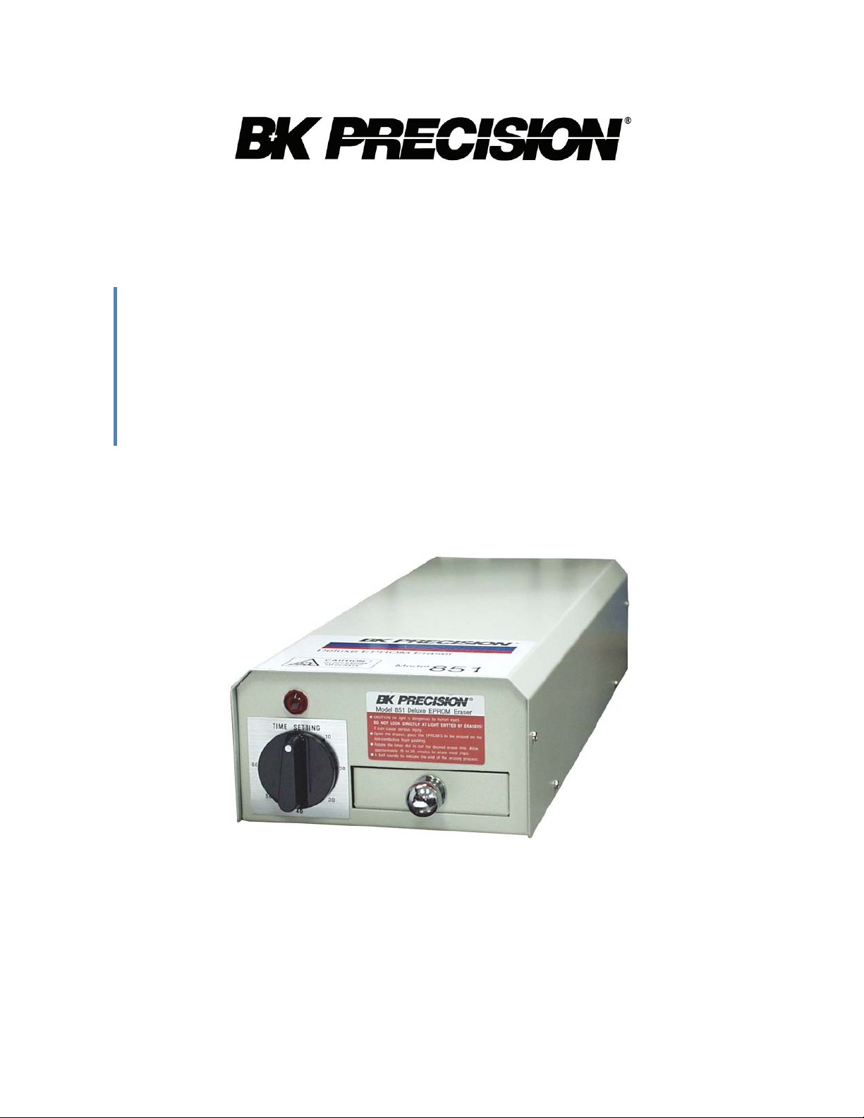
Operational Overview
The 851 was designed with safety in mind. The user cannot be exposed to UV radiation or main
voltages. The metal casing is heavy duty and the advanced design of the chip drawer means that UV
radiation can never be a hazard. EPROM's, too are cared for. They are protected from electrostatic
damage by special conductive foam, which lines the
Before connecting the uni t to t he A C pow e r s our ce , conf ir m tha t the A
voltage value labeled on the unit. Improper AC voltage will cause serious damag e to the unit.
Open the drawer and pl ace the E PROM chips to be erased on the
will era s e u p t o 4 0; 2 4 -pin
Close the drawer and rotate the timer clockwise to set the erasing
5 minutes to erase, For frequently
minutes is adequate to erase even the most stubborn EPROM. You cannot damage an EPROM by
''over-erasing'' or exposing it too long, however, you can damage it by erasing it too many times.
Most
EPROM's are good f or a few hundred erase/ w rite cycles and some
amount. An EPROM that is erased has OXFF (255 decimal) in every memory location so it's easy to
tell if
it is erased or not.
When the eraser is working, the pow e r lam p ( LE D ) w i ll light up,
operates at 253.7nm (2537 Angstroms). Intel recommends this value for the erasure of their
E
PROM's. When the setting time expires, the unit will generate a
remind the user that the cycle has been
The 851 features a pow er safe ty s w itc h loca ted insi de the dr a w er .
unit will automatically shut off to
A
lthough the 851 has safety features to reduce the risk of exposure, the user should still use the 851
with care.
EPROM's simultaneously.
used chips, allow 20-25 minutes or even longer. Usually 30
completed.
prevent the UV light leakage from harming the user's eyes.
chip drawer.
C voltage value matches the
anti-static carbon pad. The 851
time. For new chips, allow 10- 1
permit many times that
the wavelength of the UV lamp
time-off bell to conveniently
When the drawer is opened, the
4
 Loading...