

Page 1

User's Manual for
865
Universal 48-pindrive Programmer,
expandable up to 256.
866
Universal 48-pindrive Programmer with USB/LPT interface and ISP
capability
864
Universal 48-pindrive Programmer
844USB
Universal 40-pindrive Programmer with USB interface and ISP
capability
844A
Universal 40-pindrive Programmer with ISP capability
848
Universal Memory Programmer
848A
Universal Memory Programmer
849
MCS51 Series and Atmel AVR Microcontrollers Programmer with ISP
capability
Page 2

COPYRIGHT © 1997 - 2005
B+K Precision Corporation
This document is copyrighted by B+K Precision, Yorba Linda California. All rights reserved. This document or any part of it may not
be copied, reproduced or translated in any form or in any way without
the prior written permission of B+K Precision
The control program is copyright B+K Precision, Yorba Linda California. The control program or any part of it may not be analyzed,
disassembled or modified in any form, on any medium, for any purpose.
Information provided in this manual is intended to be accurate at the
moment of release, but we continuously improve all our products.
Please consult manual on
B+K Precision assumes no responsibility for misuse of this manual.
B+K Precision reserves the right to make changes or improvements to
the product described in this manual at any time without notice. This
manual contains names of companies, software products, etc., which
may be trademarks of their respective owners. B+K Precision respects
those trademarks.
www.bkprecision.com .
2
Page 3

How to use this manual
This manual explains how to install the control program and
how to use your programmer. It is assumed that the user has
some experience with PCs and installation of software. Once
you have installed the control program we recommend you
consult the context sensitive HELP within the control program
rather than the printed User's Manual. Revisions are
implemented in the context sensitive help before the printed
Users Manual.
Note: Because this User's manual is common for more than
one B+K Precision programmers, read section(s) respective
programmer you have bought, please.
This manual contains two main sections:
Quick Start
Read this section if you are an experienced user. You will find
only specific information regarding installation of the control
program and use of your programmer. For more detailed
instructions you may read the Description in detail section or
the Troubleshooting chapter for the respective programmer.
Detailed description
Read this section for the respective programmer if you are a
less experienced user or if you need detailed information. You
may find some less relevant features of programmer described
here, but all programmer features are described in this section
along with details regarding installation of the control program.
Read this section to explore all of the features provided by your
programmer.
_____________________________________
Please, download actual version of manual from
B+K Precision WEB site (
will be out of date.
www.bkprecision.com), if current one
3
Page 4

Table of contents
How to use this manual.................................................................. 3
Introduction....................................................................................... 7
Products configuration................................................................. 10
PC requirements.......................................................................... 10
Quick Start ...................................................................................... 12
Detailed description....................................................................... 14
865.................................................................................................... 15
Introduction .................................................................................. 16
865 elements ............................................................................... 19
Connecting 865 to the PC............................................................20
Manipulation with the programmed device .................................. 21
In-system serial programming by 865..........................................21
Self test and Calibration...............................................................23
Technical specification................................................................. 23
866.................................................................................................... 29
Introduction .................................................................................. 30
866 elements ............................................................................... 32
Connecting 866 to the PC............................................................ 33
Manipulation with the programmed device .................................. 34
In-system serial programming by 866.......................................... 34
Multiprogramming by 866 ............................................................ 36
Selftest and calibration................................................................. 36
Technical specification................................................................. 37
864.................................................................................................... 42
Introduction .................................................................................. 43
864 elements ............................................................................... 45
Connecting 864 to the PC............................................................ 46
Manipulation with the programmed device .................................. 47
Self test and Calibration............................................................... 47
Technical specification................................................................. 48
844USB............................................................................................ 52
Introduction .................................................................................. 53
844USB elements........................................................................ 55
Connecting 844USB to PC .......................................................... 56
Manipulation with the programmed device .................................. 56
In-system serial programming by 844USB .................................. 56
Selftest and calibration................................................................. 58
Technical specification................................................................. 58
844A................................................................................................. 63
Introduction .................................................................................. 64
844A elements............................................................................. 66
Connecting 844A to PC ............................................................... 67
Manipulation with the programmed device .................................. 67
In-system serial programming by 844A ....................................... 68
Self test and calibration................................................................ 69
Technical specification................................................................. 70
848.................................................................................................... 74
Introduction .................................................................................. 75
848 elements ............................................................................... 76
4
Page 5

Connecting 848 programmer to PC..............................................77
Manipulation with the programmed device...................................77
Self test and calibration................................................................78
Technical specification .................................................................78
848A .................................................................................................82
Introduction...................................................................................83
848A elements..............................................................................84
Connecting 848A programmer to PC ...........................................84
Manipulation with the programmed device...................................85
Technical specification .................................................................86
849....................................................................................................89
Introduction...................................................................................90
849 elements................................................................................92
849 elements................................................................................92
Connecting 849 programmer to PC..............................................92
Manipulation with the programmed device...................................93
In-System serial programming by 849..........................................93
Selftest and calibration.................................................................95
Technical specification .................................................................95
Software...........................................................................................99
The programmer software..........................................................100
File..............................................................................................102
Buffer..........................................................................................107
Device.........................................................................................113
Programmer................................................................................137
Options.......................................................................................142
Help............................................................................................146
Common notes..............................................................................149
Software .....................................................................................150
Hardware....................................................................................151
ISP (In-System Programming)....................................................152
Other...........................................................................................161
Troubleshooting and warranty ....................................................164
Throubleshooting........................................................................165
If you have an unsupported target device ..................................166
Warranty terms...........................................................................167
Appendix........................................................................................169
Appendix A - Device Problem Report form.................................170
Appendix C - AlgOR service.......................................................171
5
Page 6

Conventions used in the manual
References to the control program functions are in bold, e.g.
Load, File, Device, etc. References to control keys are written
in brackets <>, e.g. <F1>.
Terminology used in the manual:
Device any kind of programmable integrated circuits or
programmable devices
ZIF socket Zero Insertion Force socket used for insertion of
target device
Buffer part of memory or disk, used for temporary data
storage
Printer port type of port of PC (parallel), which is
primarily dedicated for printer connection.
HEX data format - format of data file, which may be read with
standard text viewers; e.g. byte 5AH is stored as
characters '5' and 'A', which mean bytes 35H and
41H. One line of this HEX file (one record)
contains start address, data bytes and all records
are secured with checksum.
6
Page 7

Introduction
7
Page 8

This user's manual covers some B+K Precision programmers:
865, 866, 864, 844USB, 844A, 848, 848A and 849.
865 is a universal programmer and logic IC tester with 48
powerful pindrivers in base configuration, expandable up to
256. This design allows to easily adding new devices to the
device list. 865 provides very competitive price but excellent
hardware design for reliable programming. Best "value for
money" in this class.
866 is a fast universal USB/LPT interfaced universal
programmer and logic IC tester with 48 powerful pindrivers.
Using build-in in-circuit serial programming (ISP) connector the
programmer is able to program ISP capable chips in-circuit.
This design allows easily add new devices to the device list.
866 is a true universal and a true low cost programmer,
providing one of the best "value for money" in today's market.
864 is a universal programmer and logic IC tester with 48
powerful pindrivers. This design allows to easily adding new
devices to the device list. 864 is a true universal and a true low
cost programmer, providing one of the best "value for money"
in today's market.
844USB is a small, fast and powerful USB interfaced
programmer of all kinds of programmable devices. Using buildin in-circuit serial programming (ISP) connector the
programmer is able to program ISP capable chips in-circuit. It
has design, which allows easily add new devices to the device
list. Nice "value for money" in this class.
844A is a small, fast and powerful programmer of all kinds of
programmable devices. Using build-in in-circuit serial
programming (ISP) connector the programmer is able to
program ISP capable chips in-circuit. It has design, which
allows to easily adding new devices to the device list. Nice
"value for money" in this class.
848 is a small and powerful EPROM, EEPROM, Flash EPROM
and serial EEPROM programmer and static RAM tester,
designed for professional mobile applications. In addition, 848
programmer with auxiliary modules support also
microprocessors (MCS48, MCS51, PIC, AVR), GALs, etc.
Programmer can work with 'true LV' device too - from 2V.
848A is a little and powerful programmer for EPROM,
EEPROM, Flash EPROM, NVRAM, serial EEPROM and static
RAM tester.
849 is little, powerful and very fast portable programmer for
MCS51 series and Atmel AVR Microcontrollers with ISP
8
Page 9

capability. 849 enables also programming serial EEPROM with
interface types IIC (24Cxx), Microwire (93Cxx) and SPI
(25Cxx).
All our programmers work with almost any IBM PC Pentium
compatible or higher, portable or desktop personal computers.
No special interface card is required to connect to the PC,
since programmers use the parallel (printer) port or USB port.
All programmers function flawlessly on systems running
Windows 95/98/Me/NT/2000/XP.
All programmers are driven by an easy-to-use, control
program with pull-down menus, hot keys and online help.
Control program is common for all these B+K PRECISION
programmers (865, 866, 864, 844USB, 844A, 848, 848A and
849).
Advanced design, including protection circuits, original brand
components and careful manufacturing allows us to provide a
one-year warranty on parts and labor for these programmers
(limited 25,000 cycle warranty on ZIF socket).
Free additional services:
• free technical support (phone/fax/e-mail).
• free lifetime software update via Web site.
Free software updates are available from our
Internet address www.bkprecision.com
We also offer the following new services in our customer
support program: Keep-Current and AlgOR.
• Keep-Current is a service by which B+K PRECISION ships
to you the latest version of the control program for
programmer and the updated user documentation. A KeepCurrent service is your hassle-free guarantee that you always
have access to the latest software and documentation, at
minimal cost.
• AlgOR (Algorithm On Request) service allows you to receive
from B+K PRECISION software support for programming
devices not yet available in the current device list.
Note: We don’t recommend use programmers 864, 848 and
848A for In-circuit programming.
9
Page 10
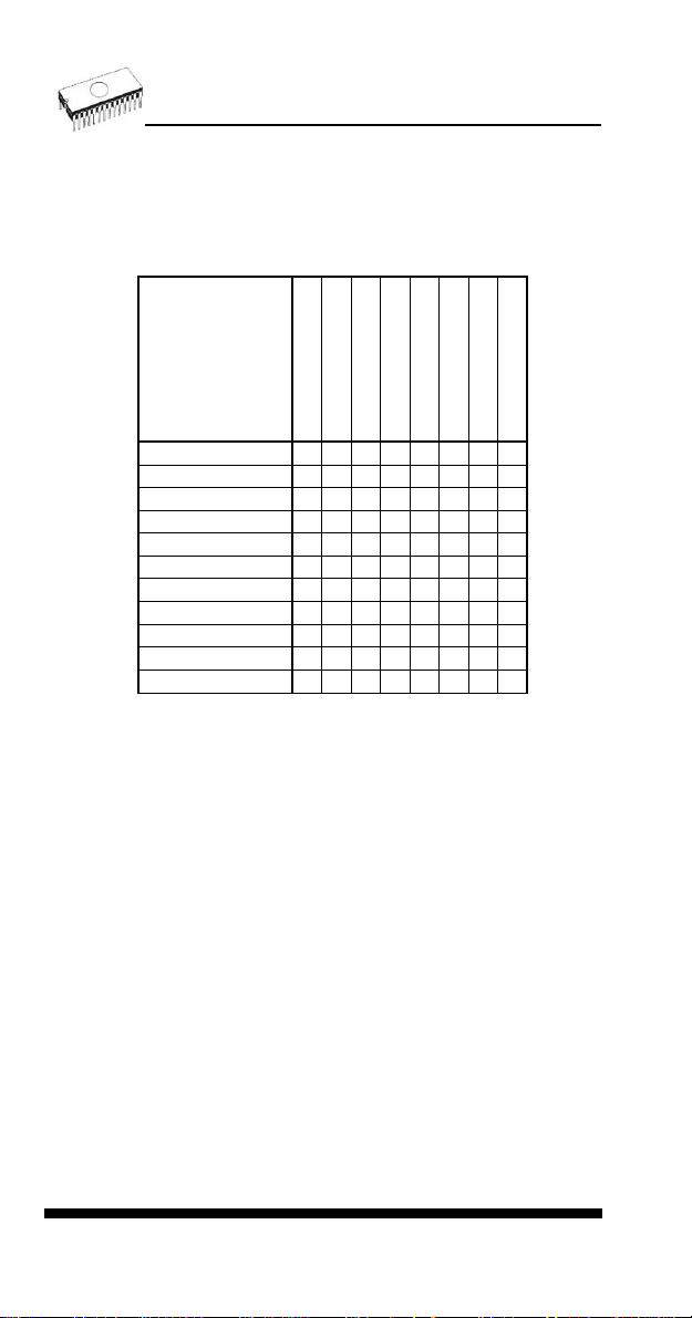
Products configuration
Before installing and using your programmer, please carefully
check that your package includes all next mentioned parts.
865
866
864
844A
848A
844USB
848
849
programmer
LPT cable
USB cable
power supply
diagnostic POD
ISP cable
ZIF anti-dust cover
User’s manual
Quick Guide
registration card
shipping case
• • • • • • • •
• • •
-
-
• • • •
-
•
- - - -
•
• • • • • • • •
• •
-
-
- -
-
- - -
•
• • •
• •
• •
• • • • •
-
-
•
• • • • •
• • •
- - - • -
• • • • • • • •
• • • • • • • •
If you find any discrepancy with respective parts list and/or if
any of these items are damaged, please contact your
distributor immediately.
PC requirements
Minimal PC requirements
• PC Pentium 166
• 32MB RAM
• one CD drive
• HDD, 40 MB free space
• operating system Windows 95/98/Me/NT/2000/XP
• one parallel (LPT) port with nothing attached (for
programmers connected via LPT port)
• USB port ver. 1.1 or later (for programmers connected via
USB port)
•
Recommended PC requirements
• Pentium PC III 800 MHz or higher
10
Page 11

• 256 MB free RAM
• one CD drive
• HDD, 50 MB free space
• operating system: Windows XP
• LPT printer port supporting EPP/ECP modes (for
programmers connected via LPT port)
• USB port ver. 1.1 or later (for programmers connected via
USB port)
Note: For convenience, we suggest that you use a
supplementary multi I/O card to provide an additional printer
port (LPT2 for example), in order to avoid sharing the same
LPT port between printer and programmer.
11
Page 12

Quick Start
12
Page 13

Installing programmer hardware
• switch off the PC and programmer
• connect the communication port of programmer t o a printer
port of PC using cable supplied
• switch on the PC
• connect the connector of the power supply adapter to the
programmer
Installing the programmer software
Run the installation program from the CD (Setup.exe) and
follow the on-screen instructions. Please, for latest information
about the programmer hardware and software see
www.bkprecision.com .
Using programmer software
Launch PG4UW.exe to enter the control program. The menu
Device contains the device manipulation commands. The
menu File contains commands for files and directories. The
menu Buffer is to be used for buffer manipulation.
Programming a device - the shortest way
Use the hot key <Alt+F5> to input the device name and/or
manufacturer to select the desired type of target device. If you
want to copy an existing device, insert it into the ZIF socket of
the programmer and then press key <F7>. If you want to
program a target device with data from a disk press key <F3>
and read the appropriate file into the buffer. Then insert your
target device into the ZIF socket. To check if the device is
blank - press key <F6>. Now you can program the device by
pressing key <F9>. After programming you may perform
additional verification by pressing key <F8>.
13
Page 14

Detailed description
14
Page 15
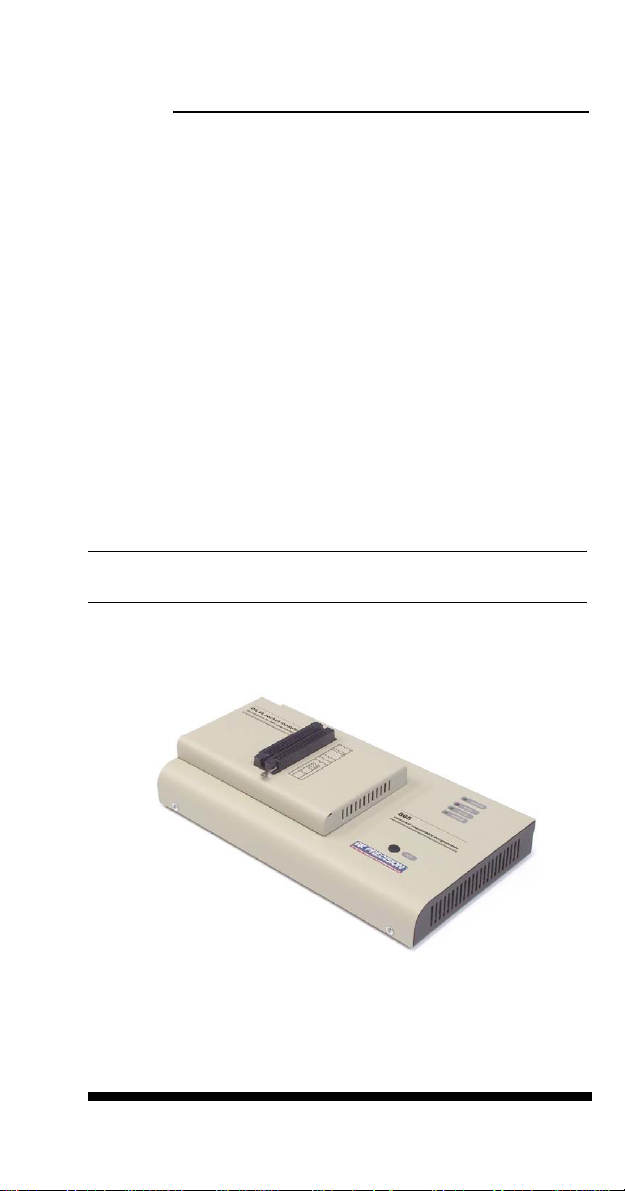
865
15
Page 16
Introduction
865 is a new generation of Windows 95/98/Me/NT/2000/XP
based B+K PRECISION universal programmers built to meet
the rigorous demands of the leading engineers and
programming centers.
865 supports all kinds of types and silicon technologies of
programmable devices. It provides very competitive price but
excellent hardware design for reliable programming. Best
"value for money" in this class.
865 interfaces with the IBM PC Pentium compatible or higher,
portable or desktop personal computers. Programmer allows
you to directly connect to your PC through any standard
parallel (printer) port (no special interface card needed). We
recommend use parallel (printer) port on PCI bus, IEEE
1284 compatible (ECP/EPP). The 865 control program
support standard IEEE1284 also.
865 offer very fast programming due high-speed FPGA driven
hardware and support of ECP/EPP parallel port. Consequently
and due special protocol is communication between PC and
865 programmer fast and very reliable. The programming
AT29C040A takes about 28 seconds it is faster than most its
competitors. As a result, this programmer is optional solution
for middle quantities programming in production or
programming centers.
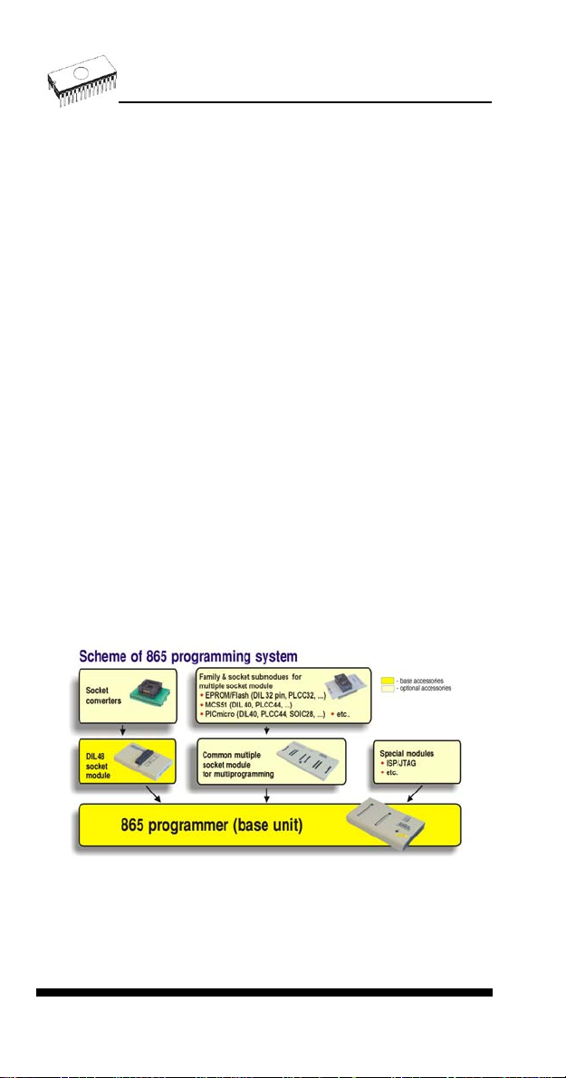
Scheme of 865 programming system
865, base configuration
• 865, base unit
• 865, DIL48 socket module
For following text, term 865 means 865 in base configuration.
16
Page 17

865 has 48 powerful pindrivers in base unit, expandable up to
256 pindrivers using "pindriver expansion" modules. Advanced
pin drivers incorporate high-quality high-speed circuitry to
deliver programming and testing performance without
overshoot or ground bounce for all device technologies. Pin
drivers operate down to 1.8V so you'll be ready to program the
full range of today's advanced low-voltage devices.
Modular design of 865 allows adapting the programmer
according to customers needs either as very flexible universal
programmer for laboratory or high efficient multi-programmer in
production line. Multiprogramming capability for most of
supported devices is accomplished by using "multiple socket"
modules.
Powerful pindriver provides logic level, pull-up/pull-down, clock,
ground, one VCC supply and two programming supply and,
certainly read, on each of all 48 pins independently. This
advanced design give it the ability to program almost every
programmable device in DIL up to 48 pins without adapter or
family specific module. Support for today and tomorrow
programmable devices gives engineers the freedom to choose
the optimum device for new design.
865 isn't only programmer, but also tester of TTL/CMOS logic
ICs and memories. Furthermore, it allows generate of userdefinable test pattern sequences.
The programmer has on-board intelligence, comprise of
powerful Microcontroller system and support devices. 865 has
been designed for multitasking operating systems and is
able to perform time-critical programming sequences
independently of the PC operating system status and without
being interrupted by any another parallel process running on
the PC. Consequently, 865 works without any problem on
systems running Windows 95/98/Me/NT/2000/XP.
The programmer performs device insertion test (wrong or
backward position) and contact check (poor contact pin-tosocket) before it programs each device. These capabilities,
supported by over current protection and signature-byte check
help prevent chip damage due to operator error.
Built-in protection circuits eliminate damage of programmed
device due to mains supply fluctuations, communication error
or if PC is frozen. In event of such errors Microcontroller in
programmer performs, independently on the PC, exactly
specified sequence of steps, so that programmed target device
remains intact. Programmer's hardware offers enough
resources for self test, that control program is any time be
able to check pindrivers, present and correct level of all
17
Page 18

voltages, check the timing and communication between
programmer and PC.
An optimally designed printed circuit minimizes negative
programming effects at the socket (such as ground bouncing,
supply voltage instability). All the inputs of the 865
programmer, including the ZIF socket, connection to PC and
power supply input, are protected against ESD to protect the
programmer and programmed circuits against damage due
ESD.
865 performs programming verification at the marginal level
of supply voltage, which, obviously, improves programming
yield, and guarantees long data retention.
Various socket converters are available to handle device in
PLCC, SOIC, PSOP, SSOP, TSOP, TSSOP, TQFP, QFN
(MLF), SDIP, BGA and other packages.
Devices with more than 48 pins are supported by
• pindriver expansion module and universal single socket
module
• simple special package converters
865 programmer is driven by an easy-to-use control program
with pull-down menu, hot keys and on-line help. Selecting of
device is performed by its class, by manufacturer or simply by
typing a fragment of vendor name and/or part number.
Standard device-related commands (read, blank check,
program, verify, erase) are boosted by some test functions
(insertion test, signature-byte check), and some special
functions (autoincrement, production mode - start immediately
after insertion of chip into socket).
All known data formats are supported. Automatic file format
detection and conversion during load of file.
The rich-featured autoincrement function enables to assign
individual serial numbers to each programmed device - or
simply increments a serial number, or the function enables to
read serial numbers or any programmed device identification
signatures from a file.
The software also provide a many informations about
programmed device. As a special, the drawing of all available
packages are provided. The software provide also explanation
of chip labeling (the meaning of prefixes and suffixes at the
chips) for each supported chip.
It is important to remember that in most cases new devices
require onl y a software upgrade since the 865 has 48 true
18
Page 19
pin drivers, which can perform as required under program
control. With our prompt service new devices can be added to
the current list within hours!
Advanced design including protection circuits, original brand
components and careful manufacturing allows us to provide a
one-year warranty on parts and labor for the 865 (limited
25,000-cycle warranty on ZIF socket).
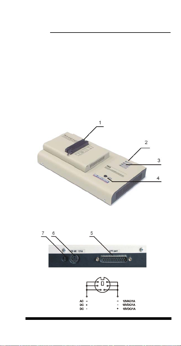
865 elements
DIL48 socket module with 48 pin ZIF socket
LED indicator power/sleep
LED indicators for work result
YES! Button
Connector for PC <-> 865 communication cable
Power supply connector
Internal use connector
Power supply connector
19
Page 20

Note: Due to low power consu mption of 865 in inactive mode,
it doesn't require power switch. When the power LED indicator
glows with a low intensity, the 865 is in inactive mode.
Connecting 865 to the PC
Switch off PC and programmer. Insert the communication
cable included with your 865 programmer package to a free
printer port on your PC. If your computer is equipped with only
one printer port, substitute the programmer cable for the printer
cable. Connect the opposite cable end to the programmer.
Screw on both connectors to counter-connectors. This is very
important. It may be uncomfortable to switch between printer
cable and programmer cable, though it is not recommended to
operate the 865 programmer through a mechanical printer
switch. Use of an electronic printer switch is impossible. But
you can install a second multi-I/O in your computer, thus
obtaining a supplementary printer port, says LPT2. So your
printer may remain on LPT1 while the programmer on LPT2.
Switch on the PC.
Connect the mains connector of the power supply (or the wallplug power supply itself) to a mains plug, and then connect the
mini-DIN connector to the programmer's connector labeled
"12VAC". At this time all 'work result' LEDs (and 'POWER'
LED) light up successive and then switch off. Once the
POWER LED lights with low brightness then the 865
programmer is ready to run.
Next run the control program for 865.
Caution! If you don't want to switch off your PC when
connecting the 865, proceed as follows:
• When connecting the programmer to the PC: FIRST insert
the communications cable and THEN the power-supply
connector.
• When disconnecting the programmer from the PC: FIRST
disconnect the power-supply connector and THEN the
communication cable.
From 865's point of view the connecting and disconnecting
sequence is irrelevant. Protection circuits on all programmer
inputs keep it safe. But think of your PC please.
Problems related to the 865 PC
interconnection, and their removing
If you have any problems with 865 PC interconnection,
see section Common notes please.
20
Page 21

Manipulation with the programmed device
After selection of desired device for your work, you can insert
into the open ZIF socket (the lever is up) and close socket (the
lever is down). The correct orientation of the programmed
device in ZIF socket is shown on the picture near ZIF socket
on the programmer's cover. The programmed device is
necessary to insert into the socket also to remove from the
socket when LED BUSY light off.
Note: Programmer's protection electronics protect the target
device and the programmer itself against either short or longterm power failures and, partly, also against a PC failure.
However, it is not possible to grant the integrity of the target
device due to incorrect, user-selected programming
parameters. Target device may be not destroyed by forced
interruption of the control program (reset or switch-off PC), by
removing the physical connection to the programmer, but the
content of actually programmed cell may remains undefined.
Don't unplug the target device from the ZIF socket during work
with devices (LED BUSY shine).
In-system serial programming by 865
For ISP programming by 865 is necessary change DIL48
socket module by ISP module.
ISP module attached to 865 programmer is manual operated
ISP programming solution, suitable for development and
low/middle volume production application.
Optimized advanced pindriver deliver programming
performance without overshoot or ground bounce for all device
technologies. Pin drivers operate down to 1.8V so you'll be
ready to program the full range of today's advanced lowvoltage devices.
The ISP programming solution performs programming
verification at the marginal level of supply voltage, which,
obviously, improves programming yield, and guarantees long
data retention.
The ISP programming solution provide also the power supply
for the target system.
21
Page 22
This ISP programming solution provides very competitive price
but excellent hardware design for reliable programming.
This ISP programming solution is driven by the same software
as the 865 programmer. The software provide full information
for ISP implementation: Description of ISP connector pins for
currently selected chip, recommended target design around incircuit programmed chip and other necessary information.
For general definition, recommendation and direction about
ISP see section Common notes / ISP please.
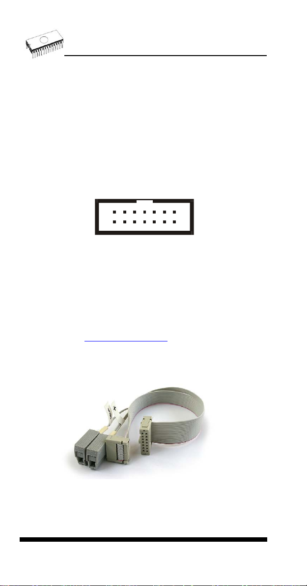
Description of ISP connector
7
11
121314
1
8910
23456
Front view at ISP connector.
Specification of ISP connector pins depends on the device,
which you want to program. You can find it in the control SW
for programmer (PG4UW), menu Device / Device Info
(Ctrl+F1). Be aware, the ISP programming way of respective
device must be selected. It is indicated by (ISP) suffix after
name of selected device.
These specifications correspond with application notes
published of device manufacturers. Used application notes you
may find on
www.bkprecision.com, section application notes.
Note: Pin no. 1 is signed by triangle scratch on ISP cable
connectors.
865 ISP cable
Warnings:
22
Page 23
• Use only attached ISP cable. When you use other ISP
cable (other material, length…), programming may occur
unreliable.
• 865 can supply programmed device (pin 1 of ISP
connector) and target system (pin 5, 13, 14 of ISP
connector) with limitation (see Technical specification / ISP
connector), but target system cannot supply 865.
• 865 apply programming voltage to target device and
checks his value (target system can modify programming
voltage). If the programming voltage is different as
expected, no action with target device will be executed.
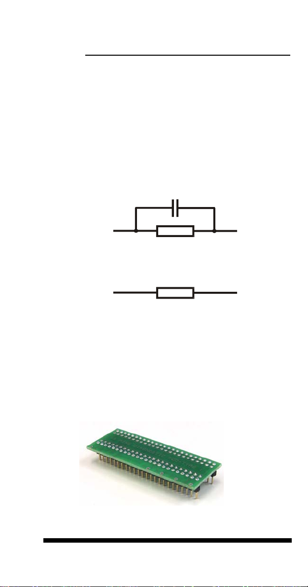
Note: H/L/read driver on pins 3 and 10
1n0
H/L/read
driver
ISP
connector
315R
H/L/read driver on pins 2, 4, 6 and 8
H/L/read
driver
ISP
connector
150R
Self test and Calibration
If you feel that your programmer does not react according to
your expectation, please run the programmer self test using
Diagnostic POD, enclosed with the standard delivery package.
For optimal results with programmer we recommend you
undertake every 6 months, an extended test and to check the
calibration. See instructions for self test in the Diagnostics
menu of PG4UW.
Technical specification
23
Page 24

HARDWARE
Base unit, DACs
• FPGA based IEEE 1284 slave printer port, up to 1MB/s
transfer rate
• on-board powerful microprocessor (20MHz) supported by
FPGA based state machine, 20MHz powered
• three D/A converters for VCCP, VPP1, and VPP2,
controllable rise and fall time
• VCCP range 0..8V/1A
• VPP1, VPP2 range 0..26V/1A
• auto calibration
• self test capability
• protection against surge and ESD on power supply input,
parallel port connection
• banana jack for ESD wrist straps
Socket, pindriver
• pin drivers: 48 as standard max. 256
• 1x VCC, 2x VPP can be connected to each pin
• perfect ground for each pin
• FPGA based TTL driver provides H, L, CLK, pull-up, pull-
down on all pindriver pins
• analog pindriver output level selectable from 1.8 V up to 26V
• current limitation, over current shutdown, power failure
shutdown
• ESD protection on each pin of socket (IEC1000-4-2: 15kV air,
8kV contact)
• continuity test: each pin is tested before every programming
operation
Socket, base configuration
• 48-pin DIL ZIF (Zero Insertion Force) socket accepts both
300/600 mil devices up to 48-pin
DEVICE SUPPORT
865 with DIL48 socket module
• EPROM: NMOS/CMOS, 2708*, 27xxx and 27Cxxx series,
with 8/16 bit data width, full support for LV series
• EEPROM: NMOS/CMOS, 28xxx, 28Cxxx, 27EExxx series,
with 8/16 bit data width
• Flash EPROM: 28Fxxx, 29Cxxx, 29Fxxx, 29BVxxx, 29LVxxx,
29Wxxx, 49Fxxx series, from 256Kbit to 32Mbit, with 8/16 bit
data width, full support for LV series
24
Page 25

• Serial E(E)PROM: 24Cxxx, 24Fxxx, 25Cxxx, 45Dxxx,
59Cxxx, 25Fxxx, 25Pxxx, 85xxx, 93Cxxx, NVM3060, MDAxxx
series, full support for LV series
• Configuration (EE)PROM: XCFxxx, XC17xxxx, XC18Vxxx,
EPCxxx, AT17xxx, 37LVxx
• 1-Wire E(E)PROM: DS1xxx, DS2xxx
• PROM: AMD, Harris, National, Philips/Signetics, Tesla, TI
• NV RAM: Dallas DSxxx, SGS/Inmos MKxxx, SIMTEK
STKxxx, XICOR 2xxx, ZMD U63x series
• PLD: Altera: MAX 3000A, MAX 7000A, MAX 7000B, MAX
7000S, MAX7000AE
• PLD: Lattice: ispGAL22V10x, ispLSI1xxx, ispLSI1xxxEA,
ispLSI2xxx, ispLSI2xxxA, ispLSI2xxxE, ispLSI2xxxV,
ispLSI2xxxVE, ispLSI2xxxVL, LC4xxxB/C/V/ZC, M4-xx/xx,
M4A3-xx/xx, M4A5-xx/xx, M4LV-xx/xx
• PLD: Xilinx: XC9500, XC9500XL, XC9500XV, CoolRunner
XPLA3, CoolRunner-II
• other PLD: SPLD/CPLD series: AMI, Atmel, AMD-Vantis,
Gould, Cypress, ICT, Lattice, NS, Philips, STM, VLSI, TI
• Microcontrollers 48 series: 87x41, 87x42, 87x48, 87x49,
87x50 series
• Microcontrollers 51 series: 87xx, 87Cxxx, 87LVxx, 89Cxxx,
89Sxxx, 89LVxxx, all manufacturers, Philips 87C748..752
series, Philips LPC series, Cygnal/Silicon Laborat. C8051
series
• Microcontrollers Intel 196 series: 87C196
KB/KC/KD/KT/KR/...
• Microcontrollers Atmel AVR: AT90Sxxxx, ATtiny, ATmega
series
• Microcontrollers Cypress: CY8Cxxxxx
• Microcontrollers ELAN: EM78Pxxx
• Microcontrollers Microchip PICmicro: PIC10xxx, PIC12xxx,
PIC16xxx, PIC17Cxxx, PIC18xxx, dsPIC series
• Microcontrollers Motorola: 68HC05, 68HC08, 68HC11 series
• Microcontrollers National: COP8xxx series
• Microcontrollers NEC: uPD78Pxxx series
• Microcontrollers Scenix (Ubicom): SXxxx series
• Microcontrollers SGS-Thomson: ST6xx, ST7xx, ST10xx
series
• Microcontrollers TI: MSP430 and MSC121x series
• Microcontrollers ZILOG: Z86/Z89xxx and Z8xxx series
• Microcontrollers other: EM Microelectronic, Fujitsu, Goal
Semiconductor, Princeton, Macronix, Winbond, Hitachi,
Holtek, Infineon(Siemens), NEC, Samsung, Toshiba, ...
I.C. Tester
• TTL type: 54,74 S/LS/ALS/H/HC/HCT series
• CMOS type: 4000, 4500 series
• static RAM: 6116.. 624000
• user definable test pattern generation
25
Page 26
865 with ISP module
• Serial E(E)PROM: IIC series
• Microcontrollers Atmel: AT89Sxxx, AT90Sxxxx, ATtiny,
ATmega series
• Microcontrollers Cypress: CY8C2xxxx
• Microcontrollers Elan: EM78Pxxx
• Microcontrollers EM Microelectronic: 4 and 8 bit series
• Microcontrollers Microchip PICmicro: PIC10xxx, PIC12xxx,
PIC16xxx, PIC17xxx, PIC18xxx, dsPIC series
• Microcontrollers Motorola/Freescale: HC08 GT, LJ, QY, QT
series
• Microcontrollers Philips: LPC series
• Microcontrollers TI: MSP430
• PLD: Lattice: ispGAL22xV10x, ispLSI1xxxEA, ispLSI2xxxE,
ispLSI2xxxV, ispLSI2xxxVE, ispLSI2xxxVL, M4-xx/xx, M4LVxx/xx, M4A3-xx/xx, M4A5-xx/xx, LC4xxxB/C/V/ZC
• Various PLD (also by Jam player/JTAG support):
• Altera: MAX 3000A, MAX 7000A, MAX 7000B, MAX 7000S,
MAX 9000, MAX II
• Xilinx: XC9500, XC9500XL, XC9500XV, CoolRunner XPLA3,
CoolRunner-II
Notes:
• Devices marked * are obsolete, programming with additional
module
• For all supported devices see actual Device list
Package support
• package support includes DIP, PLCC, SOIC, PSOP, SSOP,
TSOP, TSSOP, TQFP, QFN (MLF), SDIP, BGA and other
• support all devices in DIP with default socket
• support devices in non-DIP packages up to 48 pins with
universal adapters
• programmer is compatible with third-party adapt ers for nonDIP support
Programming speed
Device Operation Time
27C010 programming and verify 21 sec
AT29C040A programming and verify 31 sec
AM29F040 programming and verify 35 sec
PIC16C67 programming and verify 10 sec
PIC18F452 programming and verify 4 sec
Conditions: P4, 2,4GHz,ECP, Windows XP
26
Page 27

SOFTWARE
• Algorithms: only manufacturer approved or certified
algorithms are used. Custom algorithms are available at
additional cost.
• Algorithm updates: software updates are available approx.
every 2 weeks, free of charge.
• Main features: revision history, session logging, on-line help,
device and algorithm information
Device operations
• standard:
• intelligent device selection by device type, manufacturer or
typed fragment of part name
• automatic ID-based selection of EPROM/Flash EPROM
• blank check, read, verify
• program
• erase
• configuration and security bit program
• illegal bit test
• checksum
• security
• insertion test, reverse insertion check
• contact check
• ID byte check
• special
• production mode (automatic start immediately after device
insertion)
• auto device serial number increment
• statistic
• count-down mode
Buffer operations
• view/edit, find/replace
• fill/copy, move, byte swap, word/dword split
• checksum (byte, word)
• print
Supported file formats
• unformatted (raw) binary
• HEX: Intel, Intel EXT, Motorola S-record, MOS, Exormax,
Tektronix, ASCII-space-HEX
• Altera POF, JEDEC (ver. 3.0.A), eg. from ABEL, CUPL,
PALASM, TANGO PLD, OrCAD PLD, PLD Designer
ISDATA, etc.
27
Page 28

PC system requirements
See section Introduction/ PC requirements
GENERAL
• operating voltage 12..15V AC, max. 1A or 15..18V DC, max.
1A
• power consumption max. 12W active, 2.5W inactive
• dimensions 275x157x58 mm (10.8x6.2x2.3 inch)
• weight (without external adapter) 1.8kg (4 lb)
• temperature 5°C ÷ 40°C (41°F ÷ 104°F)
• humidity 20%..80%, non condensing
Package included
• 865, base unit
• 865, DIL48 socket module
• connection cable PC-programmer
• diagnostic POD for self test
• anti-dust cover for ZIF socket
• switched power adapter 100..240V AC/15V DC/1A
• user manual
• software
• registration card
• transport case
Additional services
• AlgOR
• free technical support (phone/fax/e-mail).
• free lifetime software update via Web site.
28
Page 29
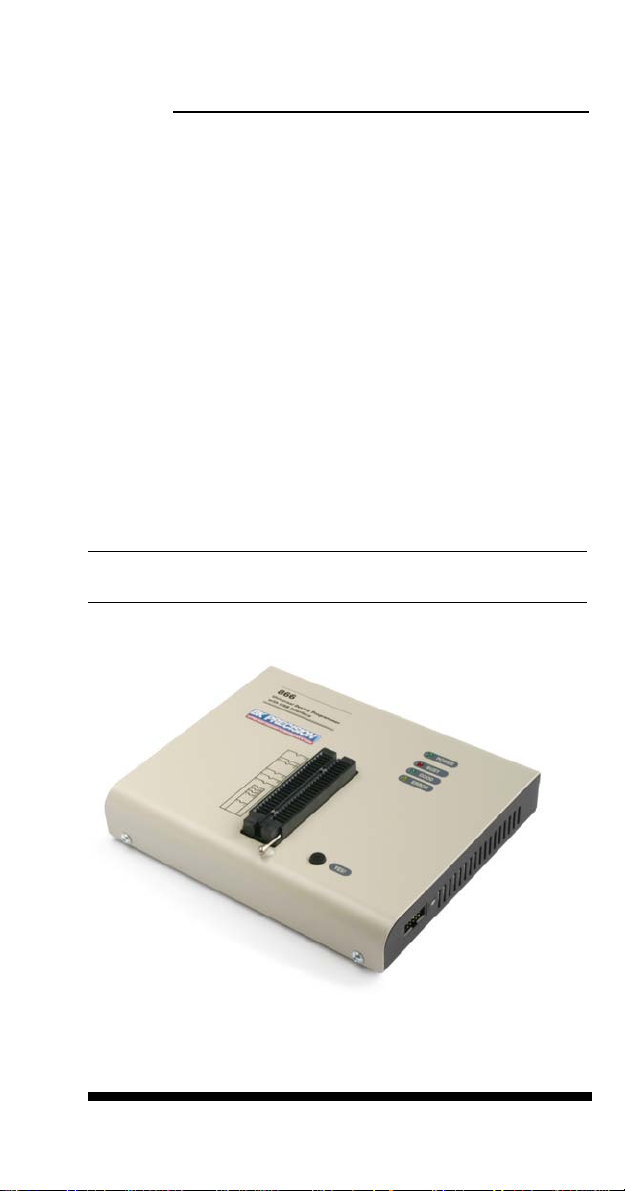
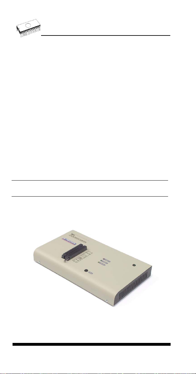
866
29
Page 30

Introduction
866 is a first member of new USB-compatible generation of
Windows 95/98/Me/NT/2000/XP based B+K PRECISION
universal programmers built to meet the strong demand of
the developers’ community for the fast, the all programmer
user community of users.
866 supports all kinds of types and silicon technologies of
today and tomorrow programmable devices without familyspecific module. Using build-in in-circuit serial programming
(ISP) connector the programmer is able to program ISP
capable chips in circuit.
866 isn't only programmer, but also tester of TTL/CMOS logic
ICs and memories. Furthermore, it allows generating userdefinable test pattern sequences.
866 provides very competitive price but excellent hardware
design for reliable programming. Probably it has best "value for
money" programmer in this class.
866 provides very fast programming due to high-speed
FPGA driven hardware and execution of time-critical routines
inside of the programmer. It is least fast than competitors in
this category.
866 interfaces with the IBM PC Pentium compatible or higher,
portable or desktop personal computers through USB (2.0) port
or any standard parallel (printer) port. Programmer also
supports IEEE1284 (ECP/EPP) high-speed parallel port.
Support of USB/LPT port connection give you choice to
connect the 866 programmer to any PC, from latest notebook
to older desktop without USB port.
866 has a FPGA based totally reconfigurable 48 powerful TTL
pindrivers provide H/L/pull_up/pull_down and read capability
for each pin of socket. Advanced pindrivers incorporate high-
quality high-speed circuitry to deliver signals without
overshoot or ground bounce for all supported devices. Pin
drivers operate down to 1.8V so you'll be ready to program the
full range of today's advanced low-voltage devices.
866 performs device insertion test (wrong or backward
position) and contact check (poor contact pin-to-socket)
before it programs each device. These capabilities, supported
by overcurrent protection and signature-byte check help
prevent chip damage due to operator error.
Built-in protection circui ts eliminate damage of programmer
and/or programmed device due environment or operator
30
Page 31

failure. All the inputs of the 866 programmer, including the ZIF
socket, connection to PC and power supply input, are
protected against ESD up to 15kV.
866 programmer performs programming verification at the
marginal level of supply voltage, which, obviously, improves
programming yield, and guarantees long data retention.
Various socket converters are available to handle device in
PLCC, SOIC, PSOP, SSOP, TSOP, TSSOP, TQFP, QFN
(MLF), SDIP, BGA and other packages.
866 programmer is driven by an easy-to-use control program
with pull-down menu, hot keys and on-line help. Selecting of
device is performed by its class, by manufacturer or simply by
typing a fragment of vendor name and/or part number.
Standard device-related commands (read, blank check,
program, verify, erase) are boosted by some test functions
(insertion test, signature-byte check), and some special
functions (autoincrement, production mode - start immediately
after insertion of chip into socket).
All known data formats are supported. Automatic file format
detection and conversion during load of file.
The rich-featured autoincrement function enables to assign
individual serial numbers to each programmed device - or
simply increments a serial number, or the function enables to
read serial numbers or any programmed device identification
signatures from a file.
The software also provides a many informations about
programmed device. As a special, the drawing of all available
packages are provided. The software provide also explanation
of chip labeling (the meaning of prefixes and suffixes at the
chips) for each supported chip.
It is important to remember that in most cases new devices
require only a software update due to the 866 is truly
universal programmer. With our prompt service you can have
new devices can be added to the current list within hours!
Advanced design including protection circuits, original brand
components and careful manufacturing allows us to provide a
three-year warranty on parts and labor for the 866 (limited
25,000-cycle warranty on ZIF socket).
31
Page 32

866 elements
48 pin ZIF socket
LED indicator power/sleep
LED indicators for work result
YES! Button
LPT connector for PC <-> 866 communication cable
USB connector for PC <-> 866 communication cable
Power supply connector
ISP connector
Power supply connector
32
Page 33

Note: Due to low power consumption of 866 in inactive state, it
doesn't require power switch. When the power L ED indicator
glows with a low intensity the 866 is in inactive mode.
Connecting 866 to the PC
Using LPT port
Switch off PC and programmer. Insert the communication
cable included with your 866 programmer package to a free
printer port on your PC. If your computer is equipped with only
one printer port, substitute the programmer cable for the printer
cable. Connect the opposite cable end to the programmer.
Screw on both connectors to counter-connectors. This is very
important. It may be uncomfortable to switch between printer
cable and programmer cable, though it is not recommended to
operate the 866 programmer through a mechanical printer
switch. Use of an electronic printer switch is impossible. But
you can install a second multi-I/O in your computer, thus
obtaining a supplementary printer port, says LPT2. So your
printer may remain on LPT1 while the programmer on LPT2.
Switch on the PC.
Connect the mains connector of the power supply to a mains
plug, and then connect the mini-DIN connector to the
programmer's connector labeled "15VDC". At this time all 'work
result' LEDs (and 'POWER' LED) light up successive and then
switch off. Once the POWER LED lights with low brightness
then the 866 programmer is ready to run.
Next run the control program for 866.
Caution! If you don't want to switch off your PC when
connecting the 866, proceed as follows:
• When connecting the programmer to the PC: FIRST insert
the communications cable and THEN the power-supply
connector.
• When disconnecting the programmer from the PC: FIRST
disconnect the power-supply connector and THEN the
communication cable.
From 866's point of view the connecting and disconnecting
sequence is irrelevant. Protection circuits on all programmer
inputs keep it safe. But think of your PC please.
Using USB port
In this case, order of connecting USB cable and power supply
to programmer is irrelevant.
33
Page 34

Problems related to the 866 PC
interconnection, and their removing
If you have any problems with 866 PC interconnection,
see section Common notes please.
Manipulation with the programmed device
After selection of desired device for your work, you can insert
into the open ZIF socket (the lever is up) and close socket (the
lever is down). The correct orientation of the programmed
device in ZIF socket is shown on the picture near ZIF socket
on the programmer's cover. The programmed device is
necessary to insert into the socket also to remove from the
socket when LED BUSY light off.
Note: Programmer's protection electronics protect the target
device and the programmer itself against either short or longterm power failures and, partly, also against a PC failure.
However, it is not possible to grant the integrity of the target
device due to incorrect, user-selected programming
parameters. Target device may be not destroyed by forced
interruption of the control program (reset or switch-off PC), by
removing the physical connection to the programmer, but the
content of actually programmed cell may remains undefined.
Don't unplug the target device from the ZIF socket during work
with device (LED BUSY shine).
In-system serial programming by 866
For general definition, recommendation and direction about
ISP see section Common notes / ISP please.
Description of 866 ISP connector
6
34
8910
5
7
234
1
Front view at ISP connector of programmer.
Specification of ISP connector pins depends on the device,
which you want to program. You can find it in the control SW
Page 35
for programmer (PG4UW), menu Device / Device Info
(Ctrl+F1). Be aware, the ISP programming way of respective
device must be selected. It is indicated by (ISP) suffix after
name of selected device.
These specifications correspond with application notes
published of device manufacturers. Used application notes you
may find on
www.bkprecision.com.
Note: Pin no. 1 is signed by triangle scratch on ISP cable
connectors.
866 ISP cable
Warnings:
• When you use 866 as ISP programmer, don’t insert
device to ZIF socket.
• When you program devices in ZIF socket, don’t insert
ISP cable to ISP connector.
• Use only attached ISP cable. When you use other ISP
cable (other material, length…), programming may occur
unreliable.
• 866 can supply programmed device (pin 1 of ISP
connector) and target system (pin 5 of ISP connector)with
limitation (see Technical specification / ISP connector), but
target system cannot supply 866.
• 866 apply programming voltage to target device and
checks his value (target system can modify programming
voltage). If the programming voltage is different as
expected, no action with target device will be executed.
Note: H/L/read 866 driver
C1
H/L/read driver
in programmer
PU/PD driver
in programmer
R1
R2
pin of ISP
connector
35
Page 36
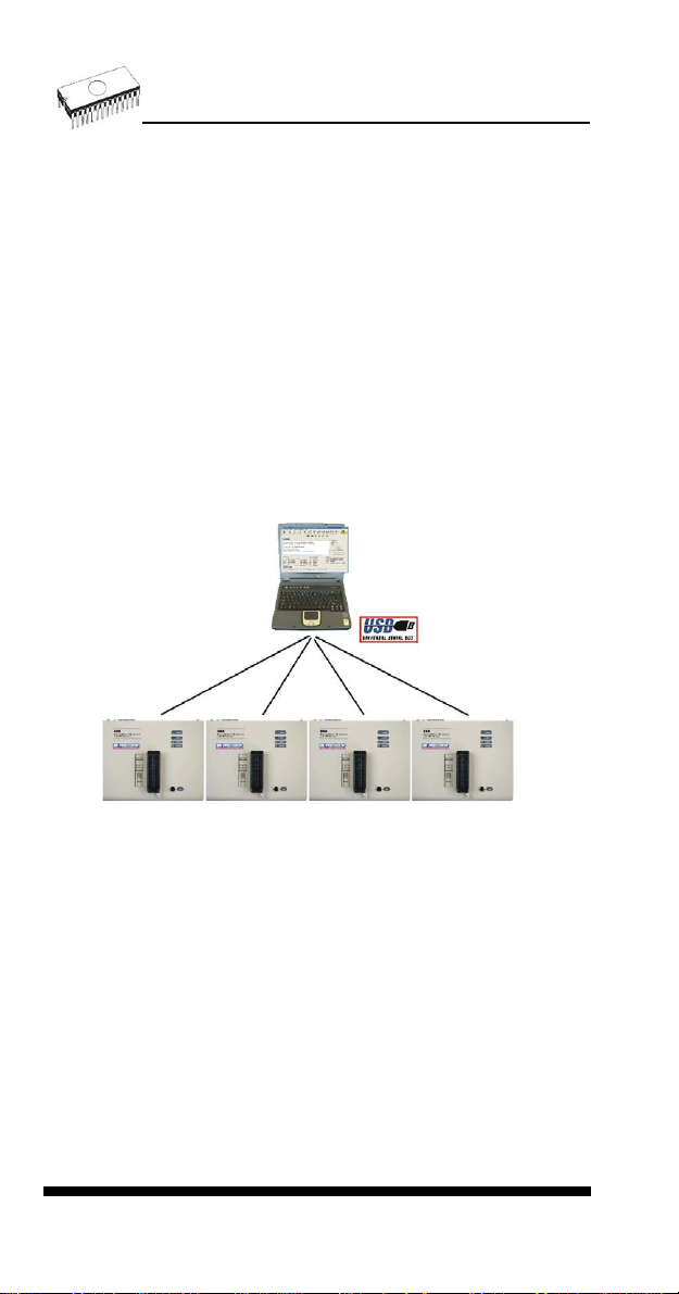
Multiprogramming by 866
Attaching of more 866 programmers to the same PC (through
USB port) is achieved a powerful multiprogramming system
with as much chips supported as 866 can and without obvious
decreasing of programming speed. It is important to know,
there is a concurrent multiprogramming - each programmer
works independently and each programmer can program
different chip, if necessary.
During installation of PG4UW at Select Additional Tasks
window check, if is allowed install 866 multiprogramming
control support.
For start of 866 multiprogramming is necessary run special
control program pg4uwmc.exe. At this program user assign
866 to control programs, may load projects for all 866 and run
PG4UW for every connected and assigned 866.
Selftest and calibration
If you feel that your programmer does not react according to
your expectation, please run the programmer selftest using
Diagnostic POD, enclosed with the standard delivery package.
For optimal results with programmer we recommend you
undertake every 6 months, an extended test and to check the
calibration. See instructions for selftest in the Diagnostics
menu of PG4UW.
36
Page 37

Technical specification
HARDWARE
Base unit, DACs
• USB 2.0 port
• FPGA based IEEE 1284 slave printer port, up to 1MB/s
transfer rate
• on-board intelligence: powerful microprocessor and FPGA
based state machine
• three D/A converters for VCCP, VPP1, and VPP2,
controllable rise and fall time
• VCCP range 0..8V/1A
• VPP1, VPP2 range 0..26V/1A
• autocalibration
• selftest capability
• protection against surge and ESD on power supply input,
parallel port connection
Socket, pindriver
• 48-pin DIL ZIF (Zero Insertion Force) socket accepts both
300/600 mil devices up to 48-pin
• pindrivers: 48 universal
• VCCP / VPP1 / VPP2 can be connected to each pin
• perfect ground for each pin
• FPGA based TTL driver provides H, L, CLK, pull-up, pull-
down on all pindriver pins
• analog pindriver output level selectable from 1.8 V up to 26V
• current limitation, overcurrent shutdown, power failure
shutdown
• ESD protection on each pin of socket (IEC1000-4-2: 15kV air,
8kV contact)
• continuity test: each pin is tested before every programming
operation
37
Page 38

ISP connector
• 10-pin male type with missinsertion lock
• 6 TTL pindrivers, provides H, L, CLK, pull-up, pull-down; level
H selectable from 1.8V up to 5V to handle all (low-voltage
including) devices.
• 1x VCCP voltage (range 2V..7V/100mA) and 1x VPP voltage
(range 2V..25V/50mA)
• programmed chip voltage (VCCP) with both source/sink
capability and voltage sense
• target system supply voltage (range 2V..6V/250mA)
DEVICE SUPPORT
Programmer, in ZIF socket
• EPROM: NMOS/CMOS, 2708*, 27xxx and 27Cxxx series,
with 8/16 bit data width, full support for LV series
• EEPROM: NMOS/CMOS, 28xxx, 28Cxxx, 27EExxx series,
with 8/16 bit data width
• Flash EPROM: 28Fxxx, 29Cxxx, 29Fxxx, 29BVxxx, 29LVxxx,
29Wxxx, 49Fxxx series, from 256Kbit to 32Mbit, with 8/16 bit
data width, full support for LV series
• Serial E(E)PROM: 24Cxxx, 24Fxxx, 25Cxxx, 45Dxxx,
59Cxxx, 25Fxxx, 25Pxxx, 85xxx, 93Cxxx, NVM3060, MDAxxx
series, full support for LV series
• Configuration (EE)PROM: XCFxxx, XC17xxxx, XC18Vxxx,
EPCxxx, AT17xxx, 37LVxx
• 1-Wire E(E)PROM: DS1xxx, DS2xxx
• PROM: AMD, Harris, National, Philips/Signetics, Tesla, TI
• NV RAM: Dallas DSxxx, SGS/Inmos MKxxx, SIMTEK
STKxxx, XICOR 2xxx, ZMD U63x series
• PLD: Altera: MAX 3000A, MAX 7000A, MAX 7000B, MAX
7000S, MAX7000AE
• PLD: Lattice: ispGAL22V10x, ispLSI1xxx, ispLSI1xxxEA,
ispLSI2xxx, ispLSI2xxxA, ispLSI2xxxE, ispLSI2xxxV,
ispLSI2xxxVE, ispLSI2xxxVL, LC4xxxB/C/V/ZC, M4-xx/xx,
M4A3-xx/xx, M4A5-xx/xx, M4LV-xx/xx
• PLD: Xilinx: XC9500, XC9500XL, XC9500XV, CoolRunner
XPLA3, CoolRunner-II
• other PLD: SPLD/CPLD series: AMI, Atmel, AMD-Vantis,
Gould, Cypress, ICT, Lattice, NS, Philips, STM, VLSI, TI
• Microcontrollers 48 series: 87x41, 87x42, 87x48, 87x49,
87x50 series
• Microcontrollers 51 series: 87xx, 87Cxxx, 87LVxx, 89Cxxx,
89Sxxx, 89LVxxx, all manufacturers, Philips LPC series
• Microcontrollers Intel 196 series: 87C196
KB/KC/KD/KT/KR/...
• Microcontrollers Atmel AVR: AT90Sxxxx, ATtiny, ATmega
series
38
Page 39

• Microcontrollers Cypress: CY8Cxxxxx
• Microcontrollers ELAN: EM78Pxxx
• Microcontrollers Microchip PICmicro: PIC10xxx, PIC12xxx,
PIC16xxx, PIC17Cxxx, PIC18xxx, dsPIC series
• Microcontrollers Motorola: 68HC05, 68HC08, 68HC11 series
• Microcontrollers National: COP8xxx series
• Microcontrollers NEC: uPD78Pxxx series
• Microcontrollers Scenix (Ubicom): SXxxx series
• Microcontrollers SGS-Thomson: ST6xx, ST7xx, ST10xx
series
• Microcontrollers TI: MSP430 and MSC121x series
• Microcontrollers ZILOG: Z86/Z89xxx and Z8xxx series
• Microcontrollers other: EM Microelectronic, Fujitsu, Goal
Semiconductor, Hitachi, Holtek, Princeton, Macronix,
Winbond, Infineon(Siemens), NEC, Samsung, Toshiba, ...
Programmer, through ISP connector
• Serial E(E)PROM: IIC series
• Microcontrollers Atmel: AT89Sxxx, AT90Sxxxx, ATtiny,
ATmega series
• Microcontrollers Cypress: CY8C2xxxx
• Microcontrollers Elan: EM78Pxxx
• Microcontrollers EM Microelectronic: 4 and 8 bit series
• Microcontrollers Microchip PICmicro: PIC10xxx, PIC12xxx,
PIC16xxx, PIC17xxx, PIC18xxx, dsPIC series
• Microcontrollers Motorola/Freescale: HC08 GT, LJ, QY, QT
series
• Microcontrollers Philips: LPC series
• Microcontrollers TI: MSP430
• PLD: Lattice: ispGAL22xV10x, ispLSI1xxxEA, ispLSI2xxxE,
ispLSI2xxxV, ispLSI2xxxVE, ispLSI2xxxVL, M4-xx/xx, M4LVxx/xx, M4A3-xx/xx, M4A5-xx/xx, LC4xxxB/C/V/ZC
• Various PLD (also by JAM player/JTAG support):
• Altera: MAX 3000A, MAX 7000A, MAX 7000B, MAX 7000S,
MAX 9000, MAX II
• Xilinx: XC9500, XC9500XL, XC9500XV, CoolRunner XPLA3,
CoolRunner-II
Notes:
• Devices marked * are obsolete, programming with additional
module
• For all supported devices see actual Device list
I.C. Tester
• TTL type: 54,74 S/LS/ALS/H/HC/HCT series
• CMOS type: 4000, 4500 series
• static RAM: 6116.. 624000
• user definable test pattern generation
Package support
• package support includes DIP, PLCC, SOIC, PSOP, SSOP,
TSOP, TSSOP, TQFP, QFN (MLF), SDIP, BGA and other
39
Page 40

• support all devices in DIP with default socket
• support devices in non-DIP packages up to 48 pins with
universal adapters
• programmer is compatible with third-party adapt ers for nonDIP support
Programming speed
Device Operation Time B
AT29C040A programming and verify 21 sec
AM29DL323DB programming and verify 38 sec
AM29DL640 programming and verify 76 sec
AT45D081 programming and verify 43 sec
AT89C51RD2 programming and verify 15 sec
PIC18F452 programming and verify 4 sec
Conditions: P4, 2,4GHz,ECP, Windows XP
SOFTWARE
• Algorithms: only manufacturer approved or certified
algorithms are used. Custom algorithms are available at
additional cost.
• Algorithm updates: software updates are available approx.
every 2 weeks, free of charge.
• Main features: revision history, session logging, on-line help,
device and algorithm information
Device operations
• standard:
• intelligent device selection by device type, manufacturer or
typed fragment of part name
• automatic ID-based selection of EPROM/Flash EPROM
• blank check, read, verify
• program
• erase
• configuration and security bit program
• illegal bit test
• checksum
• security
• insertion test, reverse insertion check
• contact check
• ID byte check
• special
• production mode (automatic start immediately after device
insertion)
• auto device serial number increment
• statistic
• count-down mode
40
Page 41

Buffer operations
• view/edit, find/replace
• fill/copy, move, byte swap, word/dword split
• checksum (byte, word)
• print
Supported file formats
• unformatted (raw) binary
• HEX: Intel, Intel EXT, Motorola S-record, MOS, Exormax,
Tektronix, ASCII-space-HEX
• Altera POF, JEDEC (ver. 3.0.A), e.g. from ABEL, CUPL,
PALASM, TANGO PLD, OrCAD PLD, PLD Designer
ISDATA, etc.
PC system requirements
See section Introduction/ PC requirements
GENERAL
• operating voltage 15..18V DC, max. 1A
• power consumption max. 12W active, about 2W inactive
• dimensions 160x190x42 mm (6.3x7.5x1.7 inch)
• weight (without external adapter) 900g (2lbs)
• temperature 5°C ÷ 40°C (41°F ÷ 104°F)
• humidity 20%..80%, non condensing
Package included
• 866 programmer
• connection cable PC-programmer, LPT port
• connection cable PC-programmer, USB port
• ISP cable
• diagnostic POD for selftest
• anti-dust cover for ZIF socket
• switching power adapter 100..240V AC/15V DC/1A
• user manual
• software
• registration card
• transport case
Additional services
• Keep Current.
• AlgOR
• free technical support (phone/fax/e-mail).
• free lifetime software update via Web site.
41
Page 42
864
42
Page 43

Introduction
864 is a universal programmer that supports programmable
integrated circuits or devices manufactured in various
technologies. Powerful internal pin-driver electronics controls
logic levels, pull-up/pull-down, clock, ground, one power supply
and two programming supplies and is able to read all 48 pins
independently. This advanced design gives 864 the ability to
handle almost every programmable device in DIL package up
to 48 pins without any adapters and/or family modules. This
design philosophy allows B+K PRECISION to easily add new
devices to the device list, giving you the freedom to implement
the optimum device in your designs.
864 is also a tester of TTL/CMOS logic circuits and various
memories. Furthermore, it can generate user-definable test
pattern sequences. 864 is a true universal and a true low-cost
programmer, providing the best "value for money" in today's
market.
864 works with the IBM PC Pentium compatible or higher,
portable or desktop personal computers. No special interface
card is required to connect to the PC since 864 uses the
standard parallel printer port. The 864 control program also
supports bi-directional protocols for the parallel connection to
the PC printer port providing fast and reliable communication
speed.
The programmer has on-board intelligence and is controlled by
powerful Microcontroller system and support devices. 864 has
been designed for multitasking operating systems and is
able to perform time-critical programming sequences
independently of the PC operating system status and without
being interrupted by any other parallel process running on the
PC. Consequently, 864 works without any problem on systems
running Windows 95/98/Me/NT/2000/XP.
864 performs device insertion test (wrong or backward
position) and contact check (poor contact pin-to-socket) before
it programs any device. These capabilities, supported by
current limit protection and signature-byte check, help prevent
chip damage due to operator error.
Built-in protection circuits help prevent damage of the target
device due to mains supply fluctuations, communication errors
or if the PC operating system fails. In the event of such errors
the 864 performs independently of the PC exactly specified
special sequences so that the target device remains intact. 864
performs self test (diagnostic tests), including verification of
pin-driver voltage/level, for accurate timing of the signals
43
Page 44

applied to the target device and for reliable communication with
the PC.
864 incorporates optimal PCB design criteria to minimize
unwanted effects at the pins of the target socket (such as
ground-bouncing and supply/programming voltage glitches). All
the inputs of the 864, including the socket, are protected
against ESD and whilst inserted the target device is also
protected against ESD damage.
864 performs programming verification at the marginal level
of supply voltage, which, obviously, improves programming
yield and guarantees long data retention.
Various socket converters are available to handle device in
PLCC, SOIC, PSOP, SSOP, TSOP, TSSOP, TQFP, QFN
(MLF), SDIP, BGA and other packages.
864 programmer is driven by an easy-to-use control program
with pull-down menu, hot keys and on-line help. Selecting of
device is performed by its class, by manufacturer or simply by
typing a fragment of vendor name and/or part number.
Standard device-related commands (read, blank check,
program, verify, erase) are boosted by some test functions
(insertion test, signature-byte check), and some special
functions (autoincrement, production mode - start immediately
after insertion of chip into socket).
All known data formats are supported. Automatic file format
detection and conversion during load of file.
The rich-featured autoincrement function enables to assign
individual serial numbers to each programmed device - or
simply increments a serial number, or the function enables to
read serial numbers or any programmed device identification
signatures from a file.
The software also provides a many informations about
programmed device. As a special, the drawing of all available
packages are provided. The software provide also explanation
of chip labeling (the meaning of prefixes and suffixes at the
chips) for each supported chip.
It is important to remember that in most cases new devices
require onl y a software upgrade since the 864 has 48 true
pin drivers, which can perform as required under program
control. With our prompt service new devices can be added to
the current list within hours!
44
Page 45

Advanced design, including protection circuits, original brand
components and careful manufacturing allows us to provide a
one-year warranty on parts and labor for the 864 (limited
25,000-cycle warranty on ZIF socket).
864 elements
48 pin ZIF (Zero Insertion Force) socket
LED indicator power/sleep
LED indicators for work result
YES! Button
Connector for PC <-> 864 communication cable
Power supply connector
Power supply connector
45
Page 46

Note: Due to low power consumption of 864 in inactive state, it
doesn't require power switch. When the power L ED indicator
glows with a low intensity the 864 is in inactive mode.
Connecting 864 to the PC
Switch off PC and programmer. Insert the communication
cable included with your 864 programmer package to a free
printer port on your PC. If your computer is equipped with only
one printer port, substitute the programmer cable for the printer
cable. Connect the opposite cable end to the programmer.
Screw on both connectors to counter-connectors. This is very
important. It may be uncomfortable to switch between printer
cable and programmer cable, though it is not recommended to
operate the 864 programmer through a mechanical printer
switch. Use of an electronic printer switch is impossible. But
you can install a second multi-I/O in your computer, thus
obtaining a supplementary printer port, says LPT2. So your
printer may remain on LPT1 while the programmer on LPT2.
Switch on the PC.
Connect the mains connector of the power supply (or the wallplug power supply itself) to a mains plug, then connect the
mini-DIN connector to the programmer's connector labeled
"12VAC". At this time all 'work result' LEDs (and 'POWER'
LED) light up successive and then switch off. Once the
POWER LED lights with low brightness then the 864
programmer is ready to run.
Next run the control program for 864.
Note: When the PC is switch off and you turn on programmer,
LED maybe not blinking, before programmer maybe
permanent on reset.
Caution! If you don't want to switch off your PC when
connecting the 864, proceed as follows:
• When connecting the programmer to the PC: FIRST insert
the communications cable and THEN the power-supply
connector.
• When disconnecting the programmer from the PC: FIRST
disconnect the power-supply connector and THEN the
communication cable.
From 864's point of view the connecting and disconnecting
sequence is irrelevant. Protection circuits on all programmer
inputs keep it safe. But think of your PC please.
46
Page 47
Problems related to the 864 PC
interconnection, and their removing
If you have any problems with 864 PC interconnection,
see section Common notes please.
Manipulation with the programmed device
After selection of desired device for your work, you can insert
into the open ZIF socket (the lever is up) and close socket (the
lever is down). The correct orientation of the programmed
device in ZIF socket is shown on the picture near ZIF socket
on the programmer's cover. The programmed device is
necessary to insert into the socket also to remove from the
socket when LED BUSY light off.
Note: Programmer's protection electronics protect the target
device and the programmer itself against either short or longterm power failures and, partly, also against a PC failure.
However, it is not possible to grant the integrity of the target
device due to incorrect, user-selected programming
parameters. Target device may be not destroyed by forced
interruption of the control program (reset or switch-off PC), by
removing the physical connection to the programmer, but the
content of actually programmed cell may remains undefined.
Don't unplug the target device from the ZIF socket during work
with devices (LED BUSY shine).
Self test and Calibration
If you feel that your programmer does not react according to
your expectation, please run the programmer self test using
Diagnostic POD, enclosed with the standard delivery package.
For optimal results with programmer we recommend you
undertake every 6 months, an extended test and to check the
calibration. See instructions for self test in the Diagnostics
menu of PG4UW.
47
Page 48

Technical specification
HARDWARE
Socket, pin drivers and DACs
• 48-pin DIL ZIF (Zero Insertion Force) socket accepts both
300/600 mil devices up to 48-pin
• Three D/A converters for VCCP, VPP1, and VPP2, with
controllable rise and fall time and current limitation
• TTL driver provides H, L, CLK, pull-up, pull-down, or tri-state
on all 48 pins
• full support of Low Voltage circuits from 1.8 V up
• autocalibration
DEVICE SUPPORT
Programmer
• EPROM: NMOS/CMOS, 1702*, 2708*, 27xxx and 27Cxxx
series, with 8/16 bit data width, full support for LV series
• EEPROM: NMOS/CMOS, 28xxx, 28Cxxx, 27EExxx series,
with 8/16 bit data width
• Flash EPROM: 28Fxxx, 29Cxxx, 29Fxxx, 29BVxxx, 29LVxxx,
29Wxxx, 49Fxxx series, from 256Kbit to 32Mbit, with 8/16 bit
data width, full support for LV series
• Serial E(E)PROM: 24Cxxx, 24Fxxx, 25Cxxx, 45Dxxx,
59Cxxx, 25Fxxx, 25Pxxx, 85xxx, 93Cxxx, NVM3060, MDAxxx
series, full support for LV series
• Configuration (EE)PROM: XCFxxx, XC17xxxx, XC18Vxxx,
EPCxxx, AT17xxx, 37LVxx
• PROM: AMD, Harris, National, Philips, Signetics, Tesla, TI
• NV RAM: Dallas DSxxx, SGS/Inmos MKxxx, SIMTEK
STKxxx, XICOR 2xxx, ZMD U63x series
• PLD: Altera: MAX 3000A, MAX 7000A, MAX 7000B, MAX
7000S, MAX7000AE
• PLD: Lattice: ispGAL22V10x, ispLSI1xxx, ispLSI1xxxEA,
ispLSI2xxx, ispLSI2xxxA, ispLSI2xxxE, ispLSI2xxxV,
ispLSI2xxxVE, M4-xx/xx, M4A3-xx/xx, M4A5-xx/xx, M4LVxx/xx
• PLD: Xilinx: XC9500, XC9500XL, XC9500XV, CoolRunner
XPLA3, CoolRunner-II
• other PLD: SPLD/CPLD series: AMI, Atmel, AMD-Vantis,
Gould, Cypress, ICT, Lattice, NS, Philips, STM, VLSI, TI
• Microcontrollers 48 series: 87x41, 87x42, 87x48, 87x49,
87x50 series
• Microcontrollers 51 series: 87xx, 87Cxxx, 87LVxx, 89Cxxx,
89Sxxx, 89LVxxx, all manufacturers, Philips 87C748..752
48
Page 49

series, Philips LPC series, Cygnal/Silicon Laborat. C8051
series
• Microcontrollers Intel 196 series: 87C196
KB/KC/KD/KT/KR/...
• Microcontrollers Atmel AVR: AT90Sxxxx, ATtiny series
• Microcontrollers ELAN: EM78Pxxx
• Microcontrollers Microchip PICmicro: PIC10xxx, PIC12Cxxx,
PIC16C5x, PIC16Cxxx, PIC17Cxxx, PIC18Cxxx, dsPIC
series
• Microcontrollers Motorola: 68HC11 series (1)
• Microcontrollers National: COP8xxx series
• Microcontrollers NEC: uPD78Pxxx series
• Microcontrollers Scenix (Ubicom): SXxxx series
• Microcontrollers SGS-Thomson: ST6xx series
• Microcontrollers TI: MSP430 series
• Microcontrollers ZILOG: Z86xxx series
• Microcontrollers other: Cypress, EM Microelectronic, Fujitsu,
Goal Semiconductor, Princeton, Macronix, Winbond, Hitachi,
Holtek, Infineon(Siemens), NEC, Samsung, Toshiba, ...
Note:
• Devices marked * are obsolete, programming with additional
module
• For all supported devices see actual Device list
I.C. Tester
• TTL type: 54,74 S/LS/ALS/H/HC/HCT series
• CMOS type: 4000, 4500 series
• static RAM: 6116 .. 624000
• user definable test pattern generation
Package support
• package support includes DIP, PLCC, SOIC, PSOP, SSOP,
TSOP, TSSOP, TQFP, QFN (MLF), SDIP, BGA and other
• support all devices in DIP with default ZIF-48 socket
• support devices in non-DIP packages up to 48 pin with
universal adapter (optional accessory, to be ordered
separately)
• compatible with third-party adapters for non-DIP support
Programming speed
Device Operation Time
27C010 programming and verify 39 sec
AT29C040A programming and verify 75 sec
AM29F040 programming and verify 165 sec
PIC16C67 programming and verify 30 sec
Conditions: P4, 2,4GHz,ECP, Windows XP
49
Page 50

SOFTWARE
• Algorithms: only manufacturer approved or certified
algorithms are used.
• Algorithm upda tes: software updates are available approx.
every 2 weeks, free of charge.
• Main features: revision history, session logging, on-line help,
device and algorithm information
Device operations
• standard:
• automatic ID-based selection of EPROM/Flash EPROM
• blank check
• read
• program
• verify
• erase
• configuration and security bit program
• illegal bit test
• checksum
• security
• insertion test
• contact check
• ID byte check
• special
• production mode (automatic start immediately after device
insertion)
• automatic device serial number incrementation
• statistics
• count-down
Buffer operations
• view/edit, find/replace
• fill/copy, move, byte swap, word/dword split
• checksum (byte, word)
• print
Supported file formats
• unformatted (raw) binary
• HEX: Intel, Intel EXT, Motorola S, MOS, Exormax, Tektronix,
ASCII-space-HEX
• POF (Altera), JEDEC (ver. 3.0.A), for example from ABEL,
CUPL, PALASM, TANGO PLD, OrCAD PLD, PLD Designer
ISDATA etc.
50
Page 51

PC system requirements
See section Introduction/ PC requirements
GENERAL
• operating voltage 12..15V AC, max.1A or 15..18V DC, max.
1A
• power consumption - max. 12W in active, 1.5W inactive
• dimensions 275x157x47 mm (10.8x6.2x1.9 inch)
• weight (without external adapter) 1.5kg (3.3 lb)
• temperature 5°C ÷ 40°C (41°F ÷ 104°F)
• humidity 20%.80%, non condensing
Package included
• 864 programmer
• connection cable PC-programmer
• diagnostic POD for self test
• anti-dust cover to ZIF socket
• switching power adapter 100..240V AC/15V DC/1A
• user manual
• software
• registration card
• transport case
Additional services
• AlgOR
• free technical support (phone/fax/e-mail).
• free lifetime software update via Web site.
51
Page 52

844USB
52
Page 53

Introduction
844USB is next member of new generation of Windows
95/98/Me/NT/2000/XP based B+K PRECISION universal
programmers. Programmer is built to meet the demands of the
development labs and field engineers to universal, but portable
programmer.
844USB is a small, fast and powerful programmer of all kinds
of programmable devices. Using build-in in-circuit serial
programming (ISP) connector the programmer is able to
program ISP capable chips in-circuit.
844USB provides very competitive price but excellent
hardware design for reliable programming. Nice "value for
money" in this class.
Very fast programming due to high-speed FPGA driven
hardware and USB 2.0 full speed port. It is surely faster than
competitors in this category.
844USB interfaces with the IBM PC Pentium compatible or
higher, portable or desktop personal computers through USB
port. Therefore you can take programmer and move it to
another PC without assembly/disassembly of PC.
844USB has 40 powerful TTL pindrivers provide
H/L/pull_up/pull_down and read capability for each pin of
socket. Advanced pindrivers incorporate high-quality highspeed circuitry to deliver signals without overshoot or ground
bounce for all supported devices. Pin drivers operate down to
1.8V so you'll be ready to program the full range of today's
advanced low-voltage devices.
The programmer performs device insertion test (wrong
device position in socket) and contact check (poor contact pinto-socket) before it programs each device. These capabilities,
supported by signature-byte check help prevent chip damage
due to operator error.
Programmer's hardware offers enough resources for selftest,
that control program is any time be able to check pindrivers,
present and correct level of all voltages, check the timing and
communication between programmer and PC.
844USB programmer performs programming verification at
the marginal level of supply voltage, which, obviously,
improves programming yield, and guarantees long data
retention.
53
Page 54

844USB programmer is driven by an easy-to-use control
program with pull-down menu, hot keys and on-line help.
Selecting of device is performed by its class, by manufacturer
or simply by typing a fragment of vendor name and/or part
number.
Standard device-related commands (read, blank check,
program, verify, erase) are boosted by some test functions
(insertion test, signature-byte check), and some special
functions (autoincrement).
All known data formats are supported. Automatic file format
detection and conversion during load of file.
The rich-featured autoincrement function enables to assign
individual serial numbers to each programmed device - or
simply increments a serial number, or the function enables to
read serial numbers or any programmed device identification
signatures from a file.
The software also provides a many informations about
programmed device. As a special, the drawings of all available
packages are provided. The software provides also
explanation of chip labeling (the meaning of prefixes and
suffixes at the chips) for each supported chip.
Various socket converters are available to handle device in
PLCC, SOIC, SSOP, TSOP, TSSOP, TQFP, QFN (MLF) and
other packages.
Advanced design, including protection circuits, original brand
components and careful manufacturing allows us to provide a
three-year warranty on parts and labor for the 844USB
(limited 25,000-cycle warranty on ZIF socket).
54
Page 55

844USB elements
40 pin ZIF socket
LED power/sleep
LED, which indicate work result
YES! button
USB connector for PC ↔ 844USB communication cable
Power supply connector
7 Connector for ISP
Power supply connector
+
55
Page 56

Note: Due to low power consumption of 844USB in inactive
state, it doesn't require power switch. When the power LED
indicator glows with a low intensity the 844USB is in inactive
mode.
Connecting 844USB to PC
For 844USB order of connecting USB cable and power supply
to programmer is irrelevant.
Problems related to the 844USB PC
interconnection, and their removing
If you have any problems with 844USB PC
interconnection, see section Common notes please.
Manipulation with the programmed device
After selection of desired device for your work, you can insert
into the open ZIF socket (the lever is up) and close socket (the
lever is down). The correct orientation of the programmed
device in ZIF socket is shown on the picture near ZIF socket
on the programmer's cover. The programmed device is
necessary to insert into the socket also to remove from the
socket when LED BUSY light off.
Warning: 844USB programmer hasn’t protection devices,
which protect the content of programmed device against critical
situations, for example power failures and PC failure
(interrupted cable...). Moreover, a device is usually destroyed
in the programming mode due to forced interruption of the
control program run (Reset or switching the computer off) due
to removing the connecting cable, or unplugging the
programmed device from the ZIF socket. Incorrectly placed
device in the ZIF socket can cause its damage or destruction.
In-system serial programming by 844USB
For general definition, recommendation and direction about
ISP see section Common notes / ISP please.
56
Page 57

Description of 844USB ISP connector
6
8910
234
5
7
1
Front view at ISP connector of programmer.
Specification of ISP connector pins depends on the device,
which you want to program. You can find it in the control SW
for programmer (PG4UW), menu Device / Device Info
(Ctrl+F1). Be aware, the ISP programming way of respective
device must be selected. It is indicated by (ISP) suffix after
name of selected device.
These specifications correspond with application notes
published of device manufacturers. Used application notes you
may find on
www.bkprecision.com, section application notes.
Note: Pin no. 1 is signed by triangle scratch on ISP cable
connectors.
844USB ISP cable
Warnings:
• When you use 844USB as ISP programmer, don’t insert
device to ZIF socket.
• When you program devices in ZIF socket, don’t insert
ISP cable to ISP connector.
• Use only attached ISP cable. When you use other ISP
cable (other material, length…), programming may occur
unreliable.
• 844USB can supply programmed device only, but target
system cannot supply 844USB.
• 844USB apply programming voltage to target device and
checks his value (target system can modify programming
voltage). If the programming voltage is different as
expected, no action with target device will be executed.
Note: H/L/read 844USB driver
57
Page 58

C1
H/L/read driver
in programmer
PU/PD driver
in programmer
R1
R2
pin of ISP
connector
Selftest and calibration
If you feel that your programmer does not react according to
your expectation, please run the programmer selftest using
Diagnostic POD, enclosed with the standard delivery package.
For optimal results with programmer we recommend you
undertake every 6 months, an extended test and to check the
calibration. See instructions for selftest in the Diagnostics
menu of PG4UW.
Technical specification
HARDWARE
Programmer
• two D/A convert ers for VCCP and VPP, controllable rise and
fall time
• VCCP range 0..7V/350mA
• VPP range 0..25V/200mA
• USB 2.0/1.1 compatible interface
• autocalibration
• selftest capability
ZIF socket, pindriver
• 40-pin DIL ZIF (Zero Insertion Force) socket accepts both
300/600 mil devices up to 40-pins
58
Page 59

• pindriver: 40 TTL pindrivers, universal GND/VCC/VPP
pindriver
• FPGA based TTL driver provides H, L, CLK, pull-up, pulldown on all pindriver pins, level H selectable from 1.8 V up to
5V
• in-circuit serial programming (ISP) capability included
• continuity test: each pin is tested before every programming
operation
ISP connector
• 10-pin male type with missinsertion lock
• 6 TTL pindrivers, provides H, L, CLK, pull-up, pull-down; level
H selectable from 1.8V up to 5V to handle all (low-voltage
including) devices.
• 1x VCCP voltage (range 2V..7V/100mA) and 1x VPP voltage
(range 2V..25V/50mA)
• programmed chip voltage (VCCP) with both source/sink
capability and voltage sense
DEVICE SUPPORT
Programmer, in ZIF socket
• EPROM: NMOS/ CMOS, 27xxx and 27Cxxx series, with 8/16
bit data width, full support of LV series (*1*2)
• EEPROM: NMOS/CMOS, 28xxx, 28Cxxx, 27EExxx series,
with 8/16 bit data width, full support of LV series (*1*2)
• Flash EPROM: 28Fxxx, 29Cxxx, 29Fxxx, 29BVxxx, 29LVxxx,
29Wxxx, 49Fxxx series, with 8/16 bit data width, full support
of LV series (*1*2)
• Serial E(E)PROM: 24Cxxx, 24Fxxx, 25Cxxx, 45Dxxx,
59Cxxx, 25Fxxx, 25Pxxx, 85xxx, 93Cxxx, full support for LV
series (*1)
• Configuration (EE)PROM: XCFxxx, 37LVxx, XC17xxxx,
EPCxxx, AT17xxx, LV series including
• NV RAM: Dallas DSxxx, SGS/Inmos MKxxx, SIMTEK
STKxxx, XICOR 2xxx, ZMD U63x series
• PLD: series: Atmel, AMD-Vantis, Cypress, ICT, Lattice, NS,
... (*1)
• microcontrollers 51 series: 87Cxxx, 87LVxx, 89Cxxx, 89Sxxx,
89LVxxx, LPC series from Atmel, Atmel W&M, Intel, Philips,
SST, Winbond (*1*2)
• microcontrollers Atmel AVR: ATtiny, AT90Sxxx, ATmega
series (*1*2)
• Microcontrollers Cypress: CY8Cxxxxx
• Microcontrollers ELAN: EM78Pxxx
• Microcontrollers EM Microelectronic: 4 and 8 bit series
• microcontrollers Microchip PICmicro: PIC10xxx, PIC12xxx,
PIC16xxx, PIC17Cxxx, PIC18xxx, dsPIC series, 8-40 pins
(*1*2)
• microcontrollers Scenix (Ubicom): SXxxx series
59
Page 60
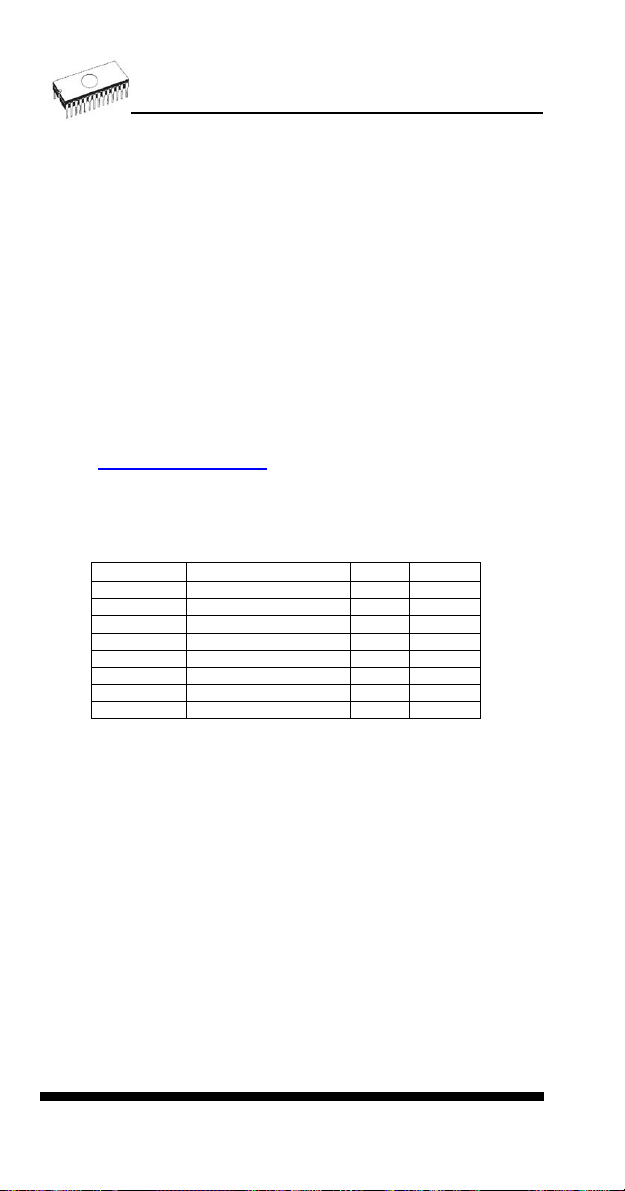
Programmer, through ISP connector
• Serial E(E)PROM: IIC series
• Microcontrollers Atmel: AT89Sxxx, AT90Sxxxx, ATtiny,
ATmega series
• Microcontrollers Cypress: CY8C2xxxx
• Microcontrollers Elan: EM78Pxxx
• Microcontrollers EM Microelectronic: 4 and 8 bit series
• Microcontrollers Microchip PICmicro: PIC10xxx, PIC12xxx,
PIC16xxx, PIC17xxx, PIC18xxx, dsPIC series
• Microcontrollers Philips: LPC series
Notes:
• (*1) - suitable adapters are available for non-DIL packages
• (*2) - There exist only few adapters for devices with more
than 40 pins. Therefore think please about more powerful
programmer (865, 866, 864), if you need to program devices
with more than 40 pins
• For all supported devices see actual Device list on
www.bkprecision.com.
I.C. Tester
• Static RAM: 6116 .. 624000
Programming speed
Device Operation Mode Time
27C010 programming and verify in ZIF 29 sec
AT29C040A programming and verify in ZIF 41 sec
AM29F040 programming and verify in ZIF 95 sec
PIC16C67 programming and verify in ZIF 10 sec
PIC18F452 programming and verify in ZIF 7 sec
AT89C52 programming and verify in ZIF 17 sec
PIC16F876A programming and verify ISP 5 sec
PIC12C508 programming and verify ISP 3 sec
Conditions: P4, 2,4GHz, USB 2.0, Windows XP
SOFTWARE
• Algorithms: only manufacturer approved or certified
algorithms are used. Custom algorithms are available at
additional cost.
• Algorithm upda tes: software updates are available approx.
every 2 weeks, free of charge.
• Main features: revision history, session logging, on-line help,
device and algorithm information
Device operations
• standard:
• intelligent device selection by device type, manufacturer or
typed fragment of part name
• blank check, read, verify
60
Page 61

• program
• erase
• configuration and security bit program
• illegal bit test
• checksum
• security
• insertion test
• contact check
• ID byte check
• special
• auto device serial number increment
• statistic
• count-down mode
Buffer operations
• view/edit, find/replace
• fill, copy, move, byte swap, word/dword split
• checksum (byte, word)
• print
File load/save
• no download time because programmer is PC controlled
• automatic file type identification
Supported file formats
• unformatted (raw) binary
• HEX: Intel, Intel EXT, Motorola S-record, MOS, Exormax,
Tektronix, ASCII-SPACE-HEX
• JEDEC (ver. 3.0.A), for example from ABEL, CUPL,
PALASM, TANGO PLD, OrCAD PLD, PLD Designer ISDATA
etc.
PC system requirements
See section Introduction/ PC requirements
GENERAL
• operating voltage 15..20V DC, max. 500mA
• power consumption max. 6W active, 1.4W inactive
• dimensions 160x97x35 mm (6.3x3.8x1.4 inch)
• weight (without external power adapter) ca. 500g (17.65 oz)
• temperature 5°C ÷ 40°C (41°F ÷ 104°F)
• humidity 20%..80%, non condensing
Package included
• 844USB programmer
• connection cable PC-programmer
61
Page 62

• ISP cable
• diagnostic POD for selftest
• anti-dust cover for ZIF socket
• wall plug adapter 15V DC/500mA, unstabilized
• user manual
• software
• registration card
• transport case
Additional services
• Keep Current
• AlgOR
• free technical support (hot line)
• free life-time software update via Internet
62
Page 63
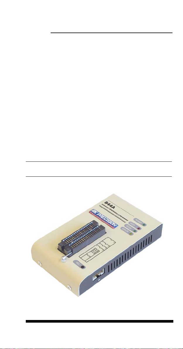
844A
63
Page 64

Introduction
844A is next member of new generation of Windows
95/98/Me/NT/2000/XP based B+K PRECISION universal
programmers. Programmer is built to meet the demands of the
development labs and field engineers to universal, but portable
programmer.
844A is a small, fast and powerful programmer of all kinds of
programmable devices. Using build-in in-circuit serial
programming (ISP) connector the programmer is able to
program ISP capable chips in-circuit.
It provides a very competitive price and excellent hardware
design for reliable programming. Great "value for money".
844A provides very fast programming due to high-speed FPGA
driven hardware and support of IEEE1284 (ECP/EPP) highspeed parallel port. It is surely faster than competitors in this
category.
844A interfaces with the IBM PC Pentium compatible or
higher, portable or desktop personal computers through any
standard parallel (printer) port (no special interface card
needed). Therefore you can take programmer and move it to
another PC without assembly/disassembly of PC.
844A has 40 powerful TTL pindrivers provide
H/L/pull_up/pull_down and read capability for each pin of
socket. Advanced pindrivers incorporate high-quality highspeed circuitry to deliver signals without overshoot or ground
bounce for all supported devices. Pin drivers operate down to
1.8V so you'll be ready to program the full range of today's
advanced low-voltage devices.
The programmer performs device insertion test (wrong
device position in socket) and contact check (poor contact pinto-socket) before it programs each device. These capabilities,
supported by signature-byte check help prevent chip damage
due to operator error.
Programmer's hardware offers enough resources for self test,
that control program is any time be able to check pindrivers,
present and correct level of all voltages, check the timing and
communication between programmer and PC.
844A programmer performs programming verification at the
marginal level of supply voltage, which, obviously, improves
programming yield, and guarantees long data retention.
64
Page 65

844A is driven by an easy-to-use control program with pulldown menu, hot keys and on-line help. Selecting of device is
performed by its class, by manufacturer or simply by typing a
fragment of vendor name and/or part number.
Standard device-related commands (read, blank check,
program, verify, erase) are boosted by some test functions
(insertion test, signature-byte check), and some special
functions (autoincrement).
All known data formats are supported. Automatic file format
detection and conversion during load of file.
The rich-featured autoincrement function enables to assign
individual serial numbers to each programmed device - or
simply increments a serial number, or the function enables to
read serial numbers or any programmed device identification
signatures from a file.
The software also provides a many informations about
programmed device. As a special, the drawing of all available
packages are provided. The software provide also explanation
of chip labeling (the meaning of prefixes and suffixes at the
chips) for each supported chip.
Various socket converters are available to handle device in
PLCC, SOIC, SSOP, TSOP, TSSOP, TQFP, QFN (MLF) and
other packages.
Advanced design, including protection circuits, original brand
components and careful manufacturing allows us to provide a
one-year warranty on parts and labor for the 844A (limited
25,000-cycle warranty on ZIF socket).
65
Page 66

844A elements
40 pin ZIF socket
LED power/sleep
LED, which indicate work result
YES! button
Connector for PC 844A communication cable
Power supply connector
7 Connector for ISP
Power supply connector
+
66
Page 67

Note: Due to low power consumption of 844A in inactive state,
it doesn't require power switch. When the power LED indicator
glows with a low intensity the 844A is in inactive mode.
Connecting 844A to PC
Switch off the PC and programmer. Insert the connection
cable, included in the 844A programmer delivery, to the free
printer port of PC. If your computer is equipped with only one
printer port, substitute the programmer cable for the printer
cable. Connect the opposite cable end to the programmer.
Screw on both connectors to counter connectors. This is very
important mainly for the connector to programmer. Though
replacing the printer cable by the programmer cable is
uncomfortable, it is not recommended to operate the 844A
programmer through a mechanical printer switch. Use of an
electronic printer switch isn't possible.
Connect the mains connector of the power supply (or wall-plug
power supply self) to a mains plug, connect the connector to
the programmer's connector labeled 15VDC. At this time all
'work result' LEDs (and 'POWER' LED) light up successive and
then switch off. Once the POWER LED lights with low
brightness then the 844A is ready to run.
Next switch on the PC and run the control program.
Caution! If you don't want to switch off your PC when
connecting the 844A, proceed as follows:
• When connecting the programmer to the PC: FIRST insert
the communications cable and THEN the power-supply
connector.
• When disconnecting the programmer from the PC: FIRST
disconnect the power-supply connector and THEN the
communication cable.
Problems related to the 844A PC
interconnection, and their removing
If you have any problems with 844A PC interconnection,
see section Common notes please.
Manipulation with the programmed device
After selection of desired device for your work, you can insert
into the open ZIF socket (the lever is up) and close socket (the
lever is down). The correct orientation of the programmed
device in ZIF socket is shown on the picture near ZIF socket
67
Page 68

on the programmer's cover. The programmed device is
necessary to insert into the socket also to remove from the
socket when LED BUSY light off.
Warning: 844A programmer hasn’t protection devices, which
protect the content of programmed device against critical
situations, for example power failures and PC failure
(interrupted cable...). Moreover, a device is usually destroyed
in the programming mode due to forced interruption of the
control program run (Reset or switching the computer off) due
to removing the connecting cable, or unplugging the
programmed device from the ZIF socket. Incorrectly placed
device in the ZIF socket can cause its damage or destruction.
In-system serial programming by 844A
For general definition, recommendation and direction about
ISP see section Common notes / ISP please.
Description of 844A ISP connector
8910
6
234
5
7
1
Front view at ISP connector of programmer.
Specification of ISP connector pins depends on the device,
which you want to program. You can find it in the control SW
for programmer (PG4UW), menu Device / Device Info
(Ctrl+F1). Be aware, the ISP programming way of respective
device must be selected. It is indicated by (ISP) suffix after
name of selected device.
These specifications correspond with application notes
published of device manufacturers. Used application notes you
may find on
www.bkprecision.com.
Note: Pin no. 1 is signed by triangle scratch on ISP cable
connectors.
68
Page 69
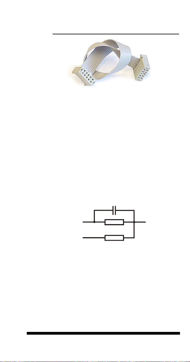
844A ISP cable
Warnings:
• When you use 844A as ISP programmer, don’t insert
device to ZIF socket.
• When you program devices in ZIF socket, don’t insert
ISP cable to ISP connector.
• Use only attached ISP cable. When you use other ISP
cable (other material, length…), programming may occur
unreliable.
• 844A can supply target device only, but target system
cannot supply 844A.
• 844A apply programming voltage to target device and
checks his value (target system can modify programming
voltage). If the programming voltage is different as
expected, no action with target device will be executed.
Note: H/L/read 844A driver
C1
H/L/read driver
in programmer
PU/PD driver
in programmer
R1
R2
Self test and calibration
pin of ISP
connector
If you feel that your programmer does not react according to
your expectation, please run the programmer selftest using
Diagnostic POD, enclosed with the standard delivery package.
For optimal results with programmer we recommend you
undertake every 6 months, an extended test and to check the
calibration. See instructions for selftest in the Diagnostics
menu of PG4UW.
69
Page 70

Technical specification
HARDWARE
Programmer
• two D/A convert ers for VCCP and VPP, controllable rise and
fall time
• VCCP range 0..7V/350mA
• VPP range 0..25V/200mA
• FPGA based IEEE 1284 slave printer port, up to 1MB/s
transfer rate
• autocalibration
• self test capability
ZIF socket, pindriver
• 40-pin DIL ZIF (Zero Insertion Force) socket accepts both
300/600 mil devices up to 40-pins
• pindriver: 40 TTL pindrivers, universal GND/VCC/VPP
pindriver
• FPGA based TTL driver provides H, L, CLK, pull-up, pulldown on all pindriver pins, level H selectable from 1.8 V up to
5V
• in-circuit serial programming (ISP) capability included
• continuity test: each pin is tested before every programming
operation
ISP connector
• 10-pin male type with missinsertion lock
• 6 TTL pindrivers, provides H, L, CLK, pull-up, pull-down; level
H selectable from 1.8V up to 5V to handle all (low-voltage
including) devices.
• 1x VCCP voltage (range 2V..7V/100mA) and 1x VPP voltage
(range 2V..25V/50mA)
• programmed chip voltage (VCCP) with both source/sink
capability and voltage sense
70
Page 71

DEVICE SUPPORT
Programmer, in ZIF socket
• EPROM: NMOS/ CMOS, 27xxx and 27Cxxx series, with 8/16
bit data width, full support of LV series (*1*2)
• EEPROM: NMOS/CMOS, 28xxx, 28Cxxx, 27EExxx series,
with 8/16 bit data width, full support of LV series (*1*2)
• Flash EPROM: 28Fxxx, 29Cxxx, 29Fxxx, 29BVxxx, 29LVxxx,
29Wxxx, 49Fxxx series, with 8/16 bit data width, full support
of LV series (*1*2)
• Serial E(E)PROM: 24Cxxx, 24Fxxx, 25Cxxx, 45Dxxx,
59Cxxx, 25Fxxx, 25Pxxx, 85xxx, 93Cxxx, full support for LV
series (*1)
• Configuration (EE)PROM: XCFxxx, 37LVxx, XC17xxxx,
EPCxxx, AT17xxx, LV series including
• NV RAM: Dallas DSxxx, SGS/Inmos MKxxx, SIMTEK
STKxxx, XICOR 2xxx, ZMD U63x series
• PLD: series: Atmel, AMD-Vantis, Cypress, ICT, Lattice, NS,
... (*1)
• microcontrollers 51 series: 87Cxxx, 87LVxx, 89Cxxx, 89Sxxx,
89LVxxx, LPC series from Atmel, Atmel W&M, Intel, Philips,
SST, Winbond (*1*2)
• microcontrollers Atmel AVR: ATtiny, AT90Sxxx, ATmega
series (*1*2)
• Microcontrollers Cypress: CY8Cxxxxx
• Microcontrollers ELAN: EM78Pxxx
• Microcontrollers EM Microelectronic: 4 and 8 bit series
• microcontrollers Microchip PICmicro: PIC10xxx, PIC12xxx,
PIC16xxx, PIC17Cxxx, PIC18xxx, dsPIC series, 8-40 pins
(*1*2)
• microcontrollers Scenix (Ubicom): SXxxx series
Programmer, through ISP connector
• Serial E(E)PROM: IIC series
• Microcontrollers Atmel: AT89Sxxx, AT90Sxxxx, ATtiny,
ATmega series
• Microcontrollers Cypress: CY8C2xxxx
• Microcontrollers Elan: EM78Pxxx
• Microcontrollers EM Microelectronic: 4 and 8 bit series
• Microcontrollers Microchip PICmicro: PIC10xxx, PIC12xxx,
PIC16xxx, PIC17xxx, PIC18xxx, dsPIC series
• Microcontrollers Philips: LPC series
Notes:
• (*1) - suitable adapters are available for non-DIL packages
• (*2) - There exist only few adapters for devices with more
than 40 pins. Therefore think please about more powerful
programmer (864, 865), if you need to program devices with
more than 40 pins
• For all supported devices see actual Device list
I.C. Tester
71
Page 72

• Static RAM: 6116 .. 624000
Programming speed
Device Operation Mode Time
27C010 programming and verify in ZIF 23 sec
AT29C040A programming and verify in ZIF 32 sec
AM29F040 programming and verify in ZIF 56 sec
PIC16C67 programming and verify in ZIF 12 sec
PIC18F452 programming and verify in ZIF 4 sec
AT89C52 programming and verify in ZIF 15 sec
PIC16F876A programming and verify ISP 5 sec
PIC12C508 programming and verify ISP 3 sec
Conditions: P4, 2,4GHz,ECP, Windows XP
SOFTWARE
• Algorithms: only manufacturer approved or certified
algorithms are used. Custom algorithms are available at
additional cost.
• Algorithm upda tes: software updates are available approx.
every 2 weeks, free of charge.
• Main features: revision history, session logging, on-line help,
device and algorithm information
Device operations
• standard:
• intelligent device selection by device type, manufacturer or
typed fragment of part name
• blank check, read, verify
• program
• erase
• configuration and security bit program
• illegal bit test
• checksum
• security
• insertion test
• contact check
• ID byte check
• special
• auto device serial number increment
• statistic
• count-down mode
Buffer operations
• view/edit, find/replace
• fill, copy, move, byte swap, word/dword split
• checksum (byte, word)
• print
72
Page 73

File load/save
• no download time because programmer is PC controlled
• automatic file type identification
Supported file formats
• unformatted (raw) binary
• HEX: Intel, Intel EXT, Motorola S-record, MOS, Exormax,
Tektronix, ASCII-SPACE-HEX
• JEDEC (ver. 3.0.A), for example from ABEL, CUPL,
PALASM, TANGO PLD, OrCAD PLD, PLD Designer ISDATA
etc.
PC system requirements
See section Introduction/ PC requirements
GENERAL
• operating voltage 15..20V DC, max. 500mA
• power consumption max. 6W active, 1.4W inactive
• dimensions 160x95x35 mm (6.3x3.7x1.4 inch)
• weight (without external power adapter) ca. 500g (17.6 oz)
• temperature 5°C ÷ 40°C (41°F ÷ 104°F)
• humidity 20%..80%, non condensing
Package included
• 844A programmer
• connection cable PC-programmer
• ISP cable
• diagnostic POD for self test
• anti-dust cover for ZIF socket
• wall plug adapter 15V DC/500mA, unstabilized
• user manual
• software
• registration card
• transport case
Additional services
• AlgOR
• free technical support (hot line)
• free life-time software update via Internet
73
Page 74

848
74
Page 75

Introduction
848 is a small and powerful EPROM, EEPROM, Flash EPROM
and serial EEPROM programmer and static RAM tester,
designed for professional mobile applications. In addition, 848
programmer with auxiliary modules support also
microprocessors (MCS48, MCS51, PICmicro, AVR), GALs,
etc. Generators for supply voltage and programming voltage
are digitally controlled and level of H can be limited, therefore
programmer can work with 'true LV' device too - from 2V.
Performance, dimensions and speed of 848 can be used both
in maintenance and in production.
848 interfaces with the IBM PC Pentium compatible or higher,
portable or desktop personal computers. Programmers allow
you to directly connect to your PC through any standard
parallel (printer) port - no special interface card is needed.
Built-in protection circuits eliminate damage of programmed
device due to mains supply error, communication error or if PC
is frozen. Programmer's hardware afford enough resources for
self test, that control program is any time be able to check
pindrivers, present of all voltages, check the timing and
communication between programmer and PC.
848 programmer performs programming verification at the
marginal level of supply voltage, which, obviously, improves
programming yield, and guarantees long data retention.
848 programmer is driven by an easy-to-use control program
with pull-down menu, hot keys and on-line help. Selecting of
device is performed by its class, by manufacturer or simply by
typing a fragment of vendor name and/or part number.
Standard device-related commands (read, blank check,
program, verify, erase) are boosted by some test functions
(signature-byte check), and some special functions
(autoincrement).
All known data formats are supported. Automatic file format
detection and conversion during load of file.
The rich-featured autoincrement function enables to assign
individual serial numbers to each programmed device - or
simply increments a serial number, or the function enables to
read serial numbers or any programmed device identification
signatures from a file.
The software also provides a many informations about
programmed device. As a special, the drawing of all available
75
Page 76

packages are provided. The software provide also explanation
of chip labeling (the meaning of prefixes and suffixes at the
chips) for each supported chip.
Various socket converters are available to handle device in
PLCC, SOIC, SSOP, TSOP, TSSOP and other packages.
Taking into consideration the 848 programmer design,
protective circuits, and the components used, the manufacturer
is able to provide a one-year warranty on parts and labor for
the programmer (limited 25,000-cycle warranty on the ZIF
socket).
848 elements
32 pin ZIF socket
LED power/sleep
LED, which indicate work result
YES! button
communication connector, for PC 848 cable connection
connector for power supply connection
76
Page 77

Power supply connector
+
Note: Due to low power consumption of 848 in inactive state, it
doesn't require power switch.
Connecting 848 programmer to PC
Switch off the PC and programmer. Insert the connection
cable, included in the 848 programmer delivery, to the free
printer port of PC. If your computer is equipped with only one
printer port, substitute the programmer cable for the printer
cable. Connect the opposite cable end to the programmer.
Screw on both connectors to counter connectors. This is very
important mainly for the connector to programmer. Though
replacing the printer cable by the programmer cable is
uncomfortable, it is not recommended to operate the 848
programmer through a mechanical printer switch. Use of an
electronic printer switch isn't possible.
Connect the mains connector of the power supply (or wall-plug
power supply self) to a mains plug, connect the connector to
the programmer's connector labeled 12VDC. Then, on the
programmer lights up LED POWER and the programmer 848
is ready to run. Next switch on the PC and run the control
program.
Caution! If you don't want to switch off your PC when
connecting the 848, proceed as follows:
• When connecting the programmer to the PC: FIRST insert
the communications cable and THEN the power-supply
connector.
• When disconnecting the programmer from the PC: FIRST
disconnect the power-supply connector and THEN the
communication cable.
Problems related to the 848 PC
interconnection, and their removing
If you have any problems with 848 PC interconnection,
see section Common notes please.
Manipulation with the programmed device
After selection of desired device for your work, you can insert
into the open ZIF socket (the lever is up) and close socket (the
77
Page 78
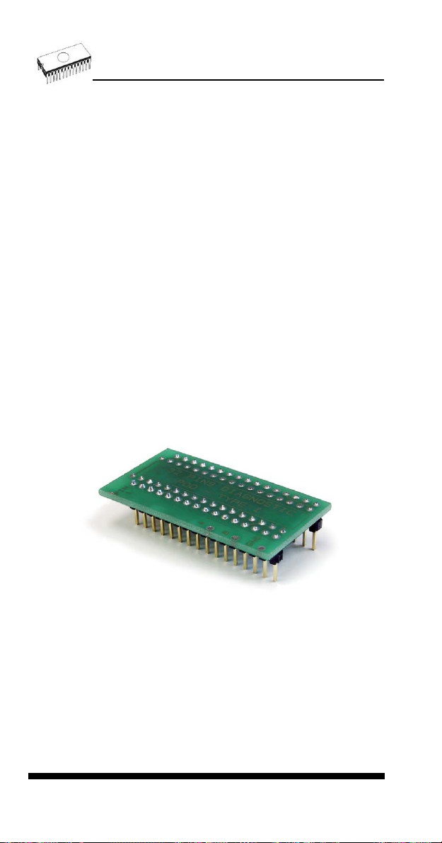
lever is down). The correct orientation of the programmed
device in ZIF socket is shown on the picture near ZIF socket
on the programmer's cover. The programmed device is
necessary to insert into the socket also to remove from the
socket when LED BUSY light off.
Warning: 848 programmer hasn’t protection devices, which
protect the content of programmed device against critical
situations, for example power failures and PC failure
(interrupted cable...). Moreover, a device is usually destroyed
in the programming mode due to forced interruption of the
control program run (Reset or switching the computer off) due
to removing the connecting cable, or unplugging the
programmed device from the ZIF socket. Incorrectly placed
device in the ZIF socket can cause its damage or destruction.
Self test and calibration
If you feel that your programmer does not react according to
your expectation, please run the programmer selftest using
Diagnostic POD, enclosed with the standard delivery package.
For optimal results with programmer we recommend you
undertake every 6 months, an extended test and to check the
calibration. See instructions for selftest in the Diagnostics
menu of PG4UW.
Technical specification
HARDWARE
Socket, pin drivers and DACs
• 32-pin DIL ZIF (Zero Insertion Force) socket accepts both
300/600 mil devices up to 32-pin
78
Page 79

• two D/A converters for VCCP and VPP, with controllable
rise/fall time and current limitation
• TTL driver provides H, L and read all 32 pins
• full support of Low Voltage circuits from 2.0 V
DEVICE SUPPORT
Programmer
• EPROM: NMOS/CMOS, 2708*, 27xxx and 27Cxxx with 8/16*
bit data width
• EEPROM: NMOS/CMOS, 28xxx, 28Cxxx, 27EExxx with
8/16* bit data width
• Flash EPROM: 28Fxxx, 29Cxxx, 29Fxxx, 29BVxxx, 29LVxxx,
29Wxxx, 49Fxxx series, from 256Kbit to 32Mbit, with 8/16* bit
data width
• Serial E(E)PROM: AT17Cxxx, 24Cxxx, 24Fxxx, 25Cxxx,
59Cxxx, 85xxx, 93Cxxx, MDAxxx* series
• NV RAM: Dallas DSxxx, SGS/Inmos MKxxx series
• PLD*: AMD PALCE, GALs, PEELs series
• microcontrollers 48 series*: 87x41, 87x42, 87x48, 87x49,
87x50 series
• microcontrollers 51 series*: 87xx, 87Cxxx, 87LVxx, 89Cxxx,
89Sxxx, 89LVxxx, Philips 87C748..752 series
• microcontrollers Microchip PICmicro*: PIC12Cxxx,
PIC16C5x, PIC16Cxxx, PIC18Cxxx series
• microcontrollers Atmel AVR*: AT90Sxxxx, ATtiny series
• microcontrollers NEC*: uPD78Pxxx series
Note:
• * - programming with additional module
• For all supported devices see actual Device list
I.C. Tester
• static RAM: 6116 .. 624000
Programming speed
Device Operation Time
NMC27C256 programming and verify 24 sec
AM27C010 programming and verify 37 sec
Conditions: P4, 2,4GHz,ECP, Windows XP
SOFTWARE
• Algorithms: only manufacturer approved or certified
algorithms are used.
• Algorithm upda tes: software updates are available approx.
every 2 weeks, free of charge.
• Main features: revision history, session logging, on-line help,
device and algorithm information
79
Page 80

Device operations
• standard:
• automatic ID-based selection of EPROM/Flash EPROM
• blank check
• read
• program
• verify
• erase
• configuration and security bit program
• illegal bit test
• security:
• contact check
• ID byte check
• special
• auto device serial number increment
Buffer operations
• view/edit, find/replace
• fill/copy, move, byte swap, word/dword split
• checksum (byte, word)
• print
Supported file formats
• unformatted (raw) binary
• HEX: Intel, Intel EXT, Motorola S, MOS, Exormax, Tektronix,
ASCII-space-HEX
• JEDEC
PC system requirements
See section Introduction/ PC requirements
GENERAL
• operating voltage 12..15V DC, max. 500mA
• power consumption 6W max.
• dimensions 160x110x50 mm (6.3x4.3x2 inch)
• weight (without external adapter) ca. 650g (23 oz)
• temperature 5°C ÷ 40°C (41°F ÷ 104°F)
• humidity 20%..80%, non condensing
Package included
• 848 programmer
• connection cable PC-programmer
• wall plug adapter, 12V DC/500mA, unstabilized
• diagnostic POD, that enable programmer's self test
80
Page 81

• anti-dust cover to ZIF socket
• software
• user manual
• registration card
• transport packing
Additional services
• AlgOR
• free technical support (phone/fax/e-mail).
• free lifetime software update via Web site.
81
Page 82

848A
82
Page 83

Introduction
848A is next member of Windows 95/98/ME/NT/2000/XP
based B+K PRECISION specialized programmers.
Programmer is built to meet the demands of the development
labs and field engineers for a specialized low-cost memory
programmer.
848A supports memory types up to 32 pins - EPROM,
EEPROM, NVRAM, Flash EPROM and serial EEPROM including low voltage types. 848A isn't only programmer, but
also static RAM tester.
848A provides very competitive price with excellent hardware
design for reliable programming. Offer outstanding "value for
money" in this class. Performance, dimensions and speed of
848A can be utilized mainly in the maintenance.
848A interfaces with the IBM PC Pentium compatible or
higher, portable or desktop personal computers through any
parallel (printer) port.
848A has the powerful TTL pindriver, which deliver signals
without overshoot or ground bounce for all supported devices.
Pin drivers provide TTL levels in the range suitable also for the
low-voltage devices. Generators for supply voltage and
programming voltage are digitally controlled in wide range of
voltages.
848A performs programming verification at the marginal level
of supply voltage, which, obviously, improves programming
yield, and guarantees long data retention.
848A is driven by an easy-to-use control program with pulldown menus, hot keys and on-line help. Selecting of device is
performed by its class, by manufacturer or simply by typing a
fragment of vendor name and/or part number.
Standard device-related commands (read, blank check,
program, verify, erase) are enhanced by some test functions
(signature-byte check), and some special functions
(autoincrement).
All known data formats are supported. Automatic file format
detection and conversion during load of file.
The rich-featured autoincrement function enables to assign
individual serial numbers to each programmed device - or
simply increments a serial number, or the function enables to
83
Page 84

read serial numbers or any programmed device identification
signatures from a file.
The software also provide a many informations about
programmed device. As a special, the drawing of all available
packages are provided. The software provides also
explanation of chip labeling (the meaning of prefixes and
suffixes at the chips) for each supported chip.
Various socket converters are available to handle device in
PLCC, SOIC, SSOP, TSOP, TSSOP and other packages.
848A elements
32 pin ZIF socket
LED power/sleep
LPT connector for PC ↔ 848A communication cable
LED, which indicate work result
Power supply connector
Power supply connector
+
Connecting 848A programmer to PC
Switch off the PC and programmer. Insert the connection
cable, included in the 848A programmer delivery, to the free
printer port of PC. If your computer is equipped with only one
84
Page 85

printer port, substitute the programmer cable for the printer
cable. Connect the opposite cable end to the programmer.
Screw on both connectors to counter connectors. This is very
important mainly for the connector to programmer. Though
replacing the printer cable by the programmer cable is
uncomfortable, it is not recommended to operate the 848A
programmer through a mechanical printer switch. Use of an
electronic printer switch isn't possible.
Connect the mains connector of the power supply (or wall-plug
power supply self) to a mains plug, connect the connector to
the appropriate programmer's connector. Then, on the
programmer lights up LED POWER and the programmer 848A
is ready to run. Next switch on the PC and run the control
program.
Caution! If you don't want to switch off your PC when
connecting the 848A, proceed as follows:
• When connecting the programmer to the PC: FIRST insert
the communications cable and THEN the power-supply
connector.
• When disconnecting the programmer from the PC: FIRST
disconnect the power-supply connector and THEN the
communication cable.
Problems related to the 848A PC
interconnection, and their removing
If you have any problems with 848A PC interconnection,
see section Common notes please.
Manipulation with the programmed device
After selection of desired device for your work, you can insert
into the open ZIF socket (the lever is up) and close socket (the
lever is down). The correct orientation of the programmed
device in ZIF socket is shown on the picture near ZIF socket
on the programmer's cover. The programmed device is
necessary to insert into the socket also to remove from the
socket when LED BUSY light off.
Warning: 848A programmer hasn’t protection devices, which
protect the content of programmed device against critical
situations, for example power failures and PC failure
(interrupted cable...). Moreover, a device is usually destroyed
in the programming mode due to forced interruption of the
control program run (Reset or switching the computer off) due
to removing the connecting cable, or unplugging the
85
Page 86

programmed device from the ZIF socket. Incorrectly placed
device in the ZIF socket can cause its damage or destruction.
Technical specification
HARDWARE
Programmer
• two D/A convert ers for VCCP and VPP, controllable rise and
fall time
• VCCP range 0..7V/350mA
• VPP range 0..25V/200mA
ZIF socket, pindriver
• 32-pin DIL ZIF (Zero Insertion Force) socket accepts both
300/600 mil devices up to 32-pins
• pindriver: TTL pindrivers and GND/VCC/VPP pindrivers,
specialized for memory programming
• TTL driver provides level H also for support of low voltage
devices
DEVICE SUPPORT
Programmer
• EPROM: NMOS/ CMOS, 27xxx and 27Cxxx series, with 8 bit
data width, full support of LV series (*1*2)
• EEPROM: NMOS/CMOS, 28xxx, 28Cxxx, 27EExxx series,
with 8 bit data width, full support of LV series (*1*2)
• Flash EPROM: 28Fxxx, 29Cxxx, 29Fxxx, 29BVxxx, 29LVxxx,
29Wxxx, 49Fxxx series, with 8 bit data width, full support of
LV series (*1*2)
• Serial E(E)P ROM: 24Cxxx, 24Fxxx, 25Cxxx, 59 Cxxx, 85xxx,
93Cxxx, full support of LV series(*1)
• NV RAM: Dallas DSxxx, SGS/Inmos MKxxx, SIMTEK
STKxxx, XICOR 2xxx, ZMD U63x series
Notes:
o (*1) - suitable adapters are available for non-DIL packages
o (*2) - There exist none adapters for devices with more than
32 pin. Therefore think please about more powerful
programmer (865, 866, 864, 844USB, 844A), if you need to
program devices with more than 32 pins
• For all supported devices see actual Device list on
www.bkprecision.com.
I.C. Tester
• Static RAM: 6116 .. 624000
86
Page 87

Programming speed
Device Operation Time
27C010 programming and verify 42 sec
AT29C040A programming and verify 45 sec
AM29F040 programming and verify 102 sec
M25P020 programming and verify 130 sec
Conditions: P4, 2,4GHz,ECP, Windows XP
SOFTWARE
• Algorithms: only manufacturer approved or certified
algorithms are used.
• Algorithm upda tes: software updates are available approx.
every 2 weeks, free of charge.
• Main features: revision history, session logging, on-line help,
device and algorithm information
Device operations
• standard:
• intelligent device selection by device type, manufacturer or
typed fragment of part name
• blank check, read, verify
• program
• erase
• configuration and protection program
• illegal bit test
• checksum
• security
• ID byte check
• special
• auto device serial number increment
• statistic
• count-down mode
Buffer operations
• view/edit, find/replace
• fill, copy, move, byte swap, word/dword split
• checksum (byte, word)
• print
File load/save
• no download time because programmer is PC controlled
• automatic file type identification
87
Page 88

Supported file formats
• unformatted (raw) binary
• HEX: Intel, Intel EXT, Motorola S-record, MOS, Exormax,
Tektronix, ASCII-SPACE-HEX
PC system requirements
See section Introduction/ PC requirements
GENERAL
• operating voltage 12..15V DC, max. 500mA
• power consumption max. 6W active
• dimensions 137x65x40 mm (5.4x2.6x1.6 inch)
• weight (without external power adapter) ca. 200g (7.06 oz)
• temperature 5°C ÷ 40°C (41°F ÷ 104°F)
• humidity 20%..80%, non condensing
Package included
• 848A programmer
• connection cable PC-programmer
• wall plug adapter 12V DC/500mA, unstabilized
• user manual
• software
• registration card
• transport case
Additional services
• Keep Current
• AlgOR
• free technical support (hot line)
• free life-time software update via Internet
88
Page 89

849
89
Page 90

Introduction
849 is a new generation of Windows 95/98/ME/NT/2000/XP
based B+K PRECISION specialized programmers.
Programmer is capable to support all today available
Microcontrollers of MCS51 series (up to 40 pins) and AVR
Microcontrollers (8-40 pins) by parallel and serial way. 849 has
been developed in close cooperation with Atmel W&M.,
therefore programmer's hardware is focused to support all
current and future Microcontrollers of Atmel W&M MCS51
family.
849 is little, very fast and powerful portable programmer for
MCS51 series and Atmel AVR microcontrollers. 849 enables
also programming of serial EEPROM with IIC (24Cxx),
Microwire (93Cxx) and SPI (25Cxx) interface types. Using
build-in in-circuit serial programming (ISP) connector
programmer is capable to program MCS51 family
microcontrollers and Atmel AVR microcontrollers in serial way.
849 provides very competitive price but excellent hardware
design for reliable programming. Nice "value for money" in this
class.
849 provides very fast programming due to high-speed FPGA
driven hardware and support of IEEE1284 (ECP/EPP) highspeed parallel port. It is surely faster than competitors in this
category.
849 interfaces with the IBM PC Pentium compatible or higher,
portable or desktop personal computers. A programmer allows
you to directly connect to your PC through any standard
parallel (printer) port - no special interface card is needed.
849 has 40 powerful TTL pindrivers provide
H/L/pull_up/pull_down and read capability for each pin of
socket. Advanced pindrivers incorporate high-quality highspeed circuitry to deliver programming without overshoot or
ground bounce for all supported devices. Pin drivers operate
down to 1.8V so you'll be ready to program the full range of
today's advanced low-voltage devices.
The programmer performs device insertion test (wrong or
backward position) and contact check (poor contact pin-tosocket) before it programs each device. These capabilities,
supported by signature-byte check help prevent chip damage
due to operator error.
Programmer's hardware offers enough resources for selftest,
that control program is any time be able to check pindrivers,
90
Page 91

present and correct level of all voltages, check the timing and
communication between programmer and PC.
849 performs programming verification at the marginal level
of supply voltage, which, obviously, improves programming
yield, and guarantees long data retention
849 programmer is driven by an easy-to-use control program
with pull-down menu, hot keys and on-line help. Selecting of
device is performed by its class, by manufacturer or simply by
typing a fragment of vendor name and/or part number.
Standard device-related commands (read, blank check,
program, verify, erase) are boosted by some test functions
(insertion test, signature-byte check), and some special
functions (autoincrement).
All known data formats are supported. Automatic file format
detection and conversion during load of file.
The rich-featured autoincrement function enables to assign
individual serial numbers to each programmed device - or
simply increments a serial number, or the function enables to
read serial numbers or any programmed device identification
signatures from a file.
The software also provide a many informations about
programmed device. As a special, the drawing of all available
packages are provided. The software provides also
explanation of chip labeling (the meaning of prefixes and
suffixes at the chips) for each supported chip.
Various socket converters are available to handle device in
PLCC, SOIC, SSOP, TSSOP, TQFP, QFN (MLF) and other
packages.
91
Page 92

849 elements
40 pin ZIF socket
LED power/sleep
LPT connector for PC ↔ 849 communication cable
LED, which indicate work result
Power supply connector
ISP connector
Power supply connector
+
Connecting 849 programmer to PC
Switch off the PC and programmer. Insert the connection
cable, included in the 849 programmer delivery, to the free
printer port of PC. If your computer is equipped with only one
printer port, substitute the programmer cable for the printer
cable. Connect the opposite cable end to the programmer.
Screw on both connectors to counter connectors. This is very
important mainly for the connector to programmer. Though
replacing the printer cable by the programmer cable is
uncomfortable, it is not recommended to operate the 849
programmer through a mechanical printer switch. Use of an
electronic printer switch isn't possible.
Connect the mains connector of the power supply (or wall-plug
power supply self) to a mains plug, connect the connector to
the appropriate programmer's connector. Then, on the
programmer lights up LED POWER and the programmer 849
is ready to run. Next switch on the PC and run the control
program.
92
Page 93

Caution! If you don't want to switch off your PC when
connecting the 849, proceed as follows:
• When connecting the programmer to the PC: FIRST insert
the communications cable and THEN the power-supply
connector.
• When disconnecting the programmer from the PC: FIRST
disconnect the power-supply connector and THEN the
communication cable.
Problems related to the 849 PC
interconnection, and their removing
If you have any problems with 849 PC interconnection,
see section Common notes please.
Manipulation with the programmed device
After selection of desired device for your work, you can insert
into the open ZIF socket (the lever is up) and close socket (the
lever is down). The correct orientation of the programmed
device in ZIF socket is shown on the picture near ZIF socket
on the programmer's cover. The programmed device is
necessary to insert into the socket also to remove from the
socket when LED BUSY light off.
Warning: 849 programmer hasn’t protection devices, which
protect the content of programmed device against critical
situations, for example power failures and PC failure
(interrupted cable...). Moreover, a device is usually destroyed
in the programming mode due to forced interruption of the
control program run (Reset or switching the computer off) due
to removing the connecting cable, or unplugging the
programmed device from the ZIF socket. Incorrectly placed
device in the ZIF socket can cause its damage or destruction.
In-System serial programming by 849
For general definition, recommendation and direction about
ISP see section Common notes / ISP please.
93
Page 94

Description of 849 ISP connector
6
12345
Front view at ISP connector of programmer.
Specification of ISP connector pins depends on the device,
which you want to program. You can find it in the control SW
for programmer (PG4UW), menu Device / Device Info
(Ctrl+F1). Be aware, the ISP programming way of respective
device must be selected. It is indicated by (ISP) suffix after
name of selected device.
These specifications correspond with Atmel application note
AVR910: In-System Programming. Used application note you
may find on
www.bkprecision.com.
Note: Pin no. 1 is signed by triangle scratch on ISP cable
connectors.
ISP cable of 849
Warnings:
• When you use 849 as ISP programmer, don’t insert
device to ZIF socket.
• When you program devices in ZIF socket, don’t insert
ISP cable to ISP connector.
• Use only attached ISP cable. When you use other ISP
cable (other material, length…), programming may occur
unreliable.
• 849 cannot supply target system and target system
cannot supply 849. Before action with target device 849
check power supply of target system. If this power supply is
different as expected, no action with device will be
executed.
94
Page 95

Note: H/L/read 849 driver.
C1
H/L/read driver
in programmer
PU/PD driver
in programmer
R1
R2
Selftest and calibration
If you feel that your programmer does not react according to
your expectation, please run the programmer selftest using
Diagnostic POD, enclosed with the standard delivery package.
For optimal results with programmer we recommend you
undertake every 6 months, an extended test and to check the
calibration. See instructions for selftest in the Diagnostics
menu of PG4UW.
pin of ISP
connector
Technical specification
HARDWARE
Socket, pin drivers and DACs
• FPGA based IEEE 1284 slave printer port, up to 1MB/s
transfer rate
• 40-pin DIL ZIF (Zero Insertion Force) socket accepts both
300/600 mil devices up to 40-pin
• two D/A converters for VCCP and VPP, controllable rise and
fall time
• VCCP range 0 – 6.5V / 150mA
• VPP range 0 – 15V / 100mA
• special GND/VCCP/VPP pindriver for MCS51 and AVR
devices
95
Page 96
• spare GND, VCCP and VPP driver, which add additional
made-by-wire GND/VCCP/VPP pin capability for future
devices
• FPGA based TTL driver provides H, L, CLK, pull-up, pulldown on and read for all pindriver pins,
• level H selectable from 1.8 V up to 5V
• in-circuit serial programming (ISP) capability included
ISP connector
• 6-pin male type with missinsertion lock
• 4 TTL pindrivers, provides H, L, CLK, pull-up, pull-down; level
H selectable from 1.8V up to 5V to handle all (low-voltage
including) devices.
• 1x target voltage sense pin
• Atmel AN AVR910 compatible pinout
DEVICE SUPPORT
Programmer, in ZIF socket
• microcontrollers MCS51 series: 87Cxxx, 87LVxx, 89Cxxx,
89Sxxx, 89LVxxx, LPC series from Atmel, Atmel W&M, Intel,
Philips, SST, Winbond, ... 8-40 pins (*1)
• microcontrollers Atmel AVR: ATtiny, AT90Sxxx, ATmega
series (parallel and serial mode), 8-40 pins (*1)
• Serial E(E)PROM: 24Cxxx, 24Fxxx, 25Cxxx, 59Cxxx, 85xxx,
93Cxxx series
Programmer, through ISP connector
• Microcontrollers Atmel: AT89Sxxx, AT90Sxxxx, ATtiny,
ATmega series
• Microcontrollers Philips: LPC series
Note:
• For all supported devices see actual Device list on
www.bkprecision.com.
Programming speed
Device Operation Time
AT89C52 programming and verify 15 sec
T87C5111 programming and verify 14 sec
Conditions: P4, 2,4GHz,ECP, Windows XP
SOFTWARE
• Algorithms: only manufacturer approved or certified
algorithms are used.
• Algorithm upda tes: software updates are available approx.
every 2 weeks, free of charge.
• Main features: revision history, session logging, on-line help,
device and algorithm information
96
Page 97

Device operations
• standard:
• intelligent device selection by device type, manufacturer or
typed fragment of part name
• blank check
• read
• program
• verify
• erase
• configuration and security bit program
• security:
• insertion test, reverse insertion check
• contact check
• ID byte check
• special:
• statistic
• count-down mode
• auto device serial number increment
Buffer operations
• view/edit, find/replace
• fill/copy, move, byte swap, word/dword split
• checksum (byte, word)
• print
Supported file formats
• unformatted (raw) binary
• HEX: Intel, Intel EXT, Motorola S, MOS, Exormax, Tektronix,
ASCII-space-HEX
PC system requirements
See section Introduction/ PC requirements
GENERAL
• operating voltage 12..15V DC, max. 500mA
• power consumption 5W max.
• dimensions 137x65x40 mm (5.4x2.6x1.6 inch)
• weight (without external power adapter) ca. 200g (7.06 oz)
• temperature 5°C ÷ 40°C (41°F ÷ 104°F)
• humidity 20%..80%, non condensing
Package included
• 849 programmer
• connection cable PC-programmer
• ISP cable
97
Page 98

• diagnostic POD for selftest
• anti-dust cover for ZIF socket
• wall plug adapter, 12V DC/500mA, unstabilized
• user manual
• software
• registration card
• transport case
Additional services
• Keep Current
• AlgOR
• free technical support (phone/fax/e-mail).
• free lifetime software update via Web site.
98
Page 99

Software
99
Page 100

The programmer software
The programmer package contains a CD with the control
program, useful utilities and additional information. The
permission to freely copy the content of the CD is granted in
order to demonstrate how B+K Precision’s programmers
works. Differences and modifications to this manual (if they
exist) may be found on
Installing of programmer software
Installing the programmer software is very easy. Insert
delivered CD to your CD drive and install program starts
automatically. Install program (setup.exe), which will guide you
through the installation process and which will do all the
necessary steps before you can first run the control program.
Program PG4UW.exe is common control programs for these
B+K Precision’s programmers. We guarantee running of these
programs under all of above mentioned operating systems
without any problems. Also background operation under
Windows is error-free.
New versions of programmer software
In order to exploit all the capabilities of programmer we
recommend using the latest version of PG4UW (see appendix
B - Keep-Current Service). You may download the latest
version of programmer software (file PG4UWARC.exe) from
our Internet site
www.bkprecision.com web site.
www.bkprecision.com.
Upgrading the programmer software
Copy PG4UWARC.exe to a temporary directory then launch it.
After extraction you will see all available files needed for the
installation process. Then redo a standard installation (run the
Setup program). You may delete all files from the temporary
folder after the installation process is complete.
Using the programmer software
The control program delivered by B+K PRECISION,
included on the CD in your package, is granted to be free
from any viruses at the moment of delivery. To increase
their safety our programs include a special algorithm for
detecting possible virus infections.
100
 Loading...